EP3479011B1 - Enceinte pour systèmes d'éclairage - Google Patents
Enceinte pour systèmes d'éclairage Download PDFInfo
- Publication number
- EP3479011B1 EP3479011B1 EP17819431.2A EP17819431A EP3479011B1 EP 3479011 B1 EP3479011 B1 EP 3479011B1 EP 17819431 A EP17819431 A EP 17819431A EP 3479011 B1 EP3479011 B1 EP 3479011B1
- Authority
- EP
- European Patent Office
- Prior art keywords
- housing
- compartment
- enclosure
- fins
- light emitting
- Prior art date
- Legal status (The legal status is an assumption and is not a legal conclusion. Google has not performed a legal analysis and makes no representation as to the accuracy of the status listed.)
- Active
Links
- XAGFODPZIPBFFR-UHFFFAOYSA-N aluminium Chemical compound [Al] XAGFODPZIPBFFR-UHFFFAOYSA-N 0.000 claims description 11
- 229910052782 aluminium Inorganic materials 0.000 claims description 11
- 239000000463 material Substances 0.000 claims description 11
- 238000012546 transfer Methods 0.000 claims description 8
- 229920001971 elastomer Polymers 0.000 claims description 6
- RYGMFSIKBFXOCR-UHFFFAOYSA-N Copper Chemical compound [Cu] RYGMFSIKBFXOCR-UHFFFAOYSA-N 0.000 claims description 4
- 239000010949 copper Substances 0.000 claims description 4
- 229910052802 copper Inorganic materials 0.000 claims description 4
- 229910000838 Al alloy Inorganic materials 0.000 claims description 3
- 238000009413 insulation Methods 0.000 claims description 3
- 229920001296 polysiloxane Polymers 0.000 claims description 3
- 239000004411 aluminium Substances 0.000 description 9
- 239000011521 glass Substances 0.000 description 6
- 230000007613 environmental effect Effects 0.000 description 4
- 230000009467 reduction Effects 0.000 description 4
- 238000010521 absorption reaction Methods 0.000 description 3
- 239000003570 air Substances 0.000 description 3
- 238000001816 cooling Methods 0.000 description 3
- 238000013021 overheating Methods 0.000 description 3
- 239000004593 Epoxy Substances 0.000 description 2
- 230000004907 flux Effects 0.000 description 2
- 229910052736 halogen Inorganic materials 0.000 description 2
- 150000002367 halogens Chemical class 0.000 description 2
- 230000017525 heat dissipation Effects 0.000 description 2
- 230000007246 mechanism Effects 0.000 description 2
- 238000000034 method Methods 0.000 description 2
- 230000005855 radiation Effects 0.000 description 2
- 239000004576 sand Substances 0.000 description 2
- 229910000679 solder Inorganic materials 0.000 description 2
- OKTJSMMVPCPJKN-UHFFFAOYSA-N Carbon Chemical compound [C] OKTJSMMVPCPJKN-UHFFFAOYSA-N 0.000 description 1
- 230000006978 adaptation Effects 0.000 description 1
- 239000012080 ambient air Substances 0.000 description 1
- 238000006243 chemical reaction Methods 0.000 description 1
- 230000000052 comparative effect Effects 0.000 description 1
- 239000002131 composite material Substances 0.000 description 1
- 238000013461 design Methods 0.000 description 1
- 238000004870 electrical engineering Methods 0.000 description 1
- 230000007717 exclusion Effects 0.000 description 1
- 229910002804 graphite Inorganic materials 0.000 description 1
- 239000010439 graphite Substances 0.000 description 1
- 238000005286 illumination Methods 0.000 description 1
- 239000004615 ingredient Substances 0.000 description 1
- 238000004519 manufacturing process Methods 0.000 description 1
- 239000011159 matrix material Substances 0.000 description 1
- 238000012986 modification Methods 0.000 description 1
- 230000004048 modification Effects 0.000 description 1
- 230000008569 process Effects 0.000 description 1
- 238000012545 processing Methods 0.000 description 1
- 238000000926 separation method Methods 0.000 description 1
- 229920002379 silicone rubber Polymers 0.000 description 1
- 238000004088 simulation Methods 0.000 description 1
- 230000007480 spreading Effects 0.000 description 1
- 238000012360 testing method Methods 0.000 description 1
- XLYOFNOQVPJJNP-UHFFFAOYSA-N water Substances O XLYOFNOQVPJJNP-UHFFFAOYSA-N 0.000 description 1
Images


Classifications
-
- F—MECHANICAL ENGINEERING; LIGHTING; HEATING; WEAPONS; BLASTING
- F21—LIGHTING
- F21V—FUNCTIONAL FEATURES OR DETAILS OF LIGHTING DEVICES OR SYSTEMS THEREOF; STRUCTURAL COMBINATIONS OF LIGHTING DEVICES WITH OTHER ARTICLES, NOT OTHERWISE PROVIDED FOR
- F21V15/00—Protecting lighting devices from damage
- F21V15/01—Housings, e.g. material or assembling of housing parts
-
- F—MECHANICAL ENGINEERING; LIGHTING; HEATING; WEAPONS; BLASTING
- F21—LIGHTING
- F21V—FUNCTIONAL FEATURES OR DETAILS OF LIGHTING DEVICES OR SYSTEMS THEREOF; STRUCTURAL COMBINATIONS OF LIGHTING DEVICES WITH OTHER ARTICLES, NOT OTHERWISE PROVIDED FOR
- F21V5/00—Refractors for light sources
- F21V5/04—Refractors for light sources of lens shape
-
- F—MECHANICAL ENGINEERING; LIGHTING; HEATING; WEAPONS; BLASTING
- F21—LIGHTING
- F21V—FUNCTIONAL FEATURES OR DETAILS OF LIGHTING DEVICES OR SYSTEMS THEREOF; STRUCTURAL COMBINATIONS OF LIGHTING DEVICES WITH OTHER ARTICLES, NOT OTHERWISE PROVIDED FOR
- F21V23/00—Arrangement of electric circuit elements in or on lighting devices
- F21V23/003—Arrangement of electric circuit elements in or on lighting devices the elements being electronics drivers or controllers for operating the light source, e.g. for a LED array
- F21V23/004—Arrangement of electric circuit elements in or on lighting devices the elements being electronics drivers or controllers for operating the light source, e.g. for a LED array arranged on a substrate, e.g. a printed circuit board
- F21V23/005—Arrangement of electric circuit elements in or on lighting devices the elements being electronics drivers or controllers for operating the light source, e.g. for a LED array arranged on a substrate, e.g. a printed circuit board the substrate is supporting also the light source
-
- F—MECHANICAL ENGINEERING; LIGHTING; HEATING; WEAPONS; BLASTING
- F21—LIGHTING
- F21V—FUNCTIONAL FEATURES OR DETAILS OF LIGHTING DEVICES OR SYSTEMS THEREOF; STRUCTURAL COMBINATIONS OF LIGHTING DEVICES WITH OTHER ARTICLES, NOT OTHERWISE PROVIDED FOR
- F21V23/00—Arrangement of electric circuit elements in or on lighting devices
- F21V23/003—Arrangement of electric circuit elements in or on lighting devices the elements being electronics drivers or controllers for operating the light source, e.g. for a LED array
- F21V23/007—Arrangement of electric circuit elements in or on lighting devices the elements being electronics drivers or controllers for operating the light source, e.g. for a LED array enclosed in a casing
- F21V23/008—Arrangement of electric circuit elements in or on lighting devices the elements being electronics drivers or controllers for operating the light source, e.g. for a LED array enclosed in a casing the casing being outside the housing of the lighting device
-
- F—MECHANICAL ENGINEERING; LIGHTING; HEATING; WEAPONS; BLASTING
- F21—LIGHTING
- F21V—FUNCTIONAL FEATURES OR DETAILS OF LIGHTING DEVICES OR SYSTEMS THEREOF; STRUCTURAL COMBINATIONS OF LIGHTING DEVICES WITH OTHER ARTICLES, NOT OTHERWISE PROVIDED FOR
- F21V23/00—Arrangement of electric circuit elements in or on lighting devices
- F21V23/003—Arrangement of electric circuit elements in or on lighting devices the elements being electronics drivers or controllers for operating the light source, e.g. for a LED array
- F21V23/007—Arrangement of electric circuit elements in or on lighting devices the elements being electronics drivers or controllers for operating the light source, e.g. for a LED array enclosed in a casing
- F21V23/009—Arrangement of electric circuit elements in or on lighting devices the elements being electronics drivers or controllers for operating the light source, e.g. for a LED array enclosed in a casing the casing being inside the housing of the lighting device
-
- F—MECHANICAL ENGINEERING; LIGHTING; HEATING; WEAPONS; BLASTING
- F21—LIGHTING
- F21V—FUNCTIONAL FEATURES OR DETAILS OF LIGHTING DEVICES OR SYSTEMS THEREOF; STRUCTURAL COMBINATIONS OF LIGHTING DEVICES WITH OTHER ARTICLES, NOT OTHERWISE PROVIDED FOR
- F21V29/00—Protecting lighting devices from thermal damage; Cooling or heating arrangements specially adapted for lighting devices or systems
- F21V29/50—Cooling arrangements
- F21V29/502—Cooling arrangements characterised by the adaptation for cooling of specific components
- F21V29/508—Cooling arrangements characterised by the adaptation for cooling of specific components of electrical circuits
-
- F—MECHANICAL ENGINEERING; LIGHTING; HEATING; WEAPONS; BLASTING
- F21—LIGHTING
- F21V—FUNCTIONAL FEATURES OR DETAILS OF LIGHTING DEVICES OR SYSTEMS THEREOF; STRUCTURAL COMBINATIONS OF LIGHTING DEVICES WITH OTHER ARTICLES, NOT OTHERWISE PROVIDED FOR
- F21V29/00—Protecting lighting devices from thermal damage; Cooling or heating arrangements specially adapted for lighting devices or systems
- F21V29/50—Cooling arrangements
- F21V29/70—Cooling arrangements characterised by passive heat-dissipating elements, e.g. heat-sinks
- F21V29/74—Cooling arrangements characterised by passive heat-dissipating elements, e.g. heat-sinks with fins or blades
- F21V29/76—Cooling arrangements characterised by passive heat-dissipating elements, e.g. heat-sinks with fins or blades with essentially identical parallel planar fins or blades, e.g. with comb-like cross-section
-
- F—MECHANICAL ENGINEERING; LIGHTING; HEATING; WEAPONS; BLASTING
- F21—LIGHTING
- F21V—FUNCTIONAL FEATURES OR DETAILS OF LIGHTING DEVICES OR SYSTEMS THEREOF; STRUCTURAL COMBINATIONS OF LIGHTING DEVICES WITH OTHER ARTICLES, NOT OTHERWISE PROVIDED FOR
- F21V29/00—Protecting lighting devices from thermal damage; Cooling or heating arrangements specially adapted for lighting devices or systems
- F21V29/85—Protecting lighting devices from thermal damage; Cooling or heating arrangements specially adapted for lighting devices or systems characterised by the material
-
- F—MECHANICAL ENGINEERING; LIGHTING; HEATING; WEAPONS; BLASTING
- F21—LIGHTING
- F21V—FUNCTIONAL FEATURES OR DETAILS OF LIGHTING DEVICES OR SYSTEMS THEREOF; STRUCTURAL COMBINATIONS OF LIGHTING DEVICES WITH OTHER ARTICLES, NOT OTHERWISE PROVIDED FOR
- F21V29/00—Protecting lighting devices from thermal damage; Cooling or heating arrangements specially adapted for lighting devices or systems
- F21V29/50—Cooling arrangements
- F21V29/502—Cooling arrangements characterised by the adaptation for cooling of specific components
- F21V29/507—Cooling arrangements characterised by the adaptation for cooling of specific components of means for protecting lighting devices from damage, e.g. housings
-
- F—MECHANICAL ENGINEERING; LIGHTING; HEATING; WEAPONS; BLASTING
- F21—LIGHTING
- F21V—FUNCTIONAL FEATURES OR DETAILS OF LIGHTING DEVICES OR SYSTEMS THEREOF; STRUCTURAL COMBINATIONS OF LIGHTING DEVICES WITH OTHER ARTICLES, NOT OTHERWISE PROVIDED FOR
- F21V29/00—Protecting lighting devices from thermal damage; Cooling or heating arrangements specially adapted for lighting devices or systems
- F21V29/50—Cooling arrangements
- F21V29/70—Cooling arrangements characterised by passive heat-dissipating elements, e.g. heat-sinks
-
- F—MECHANICAL ENGINEERING; LIGHTING; HEATING; WEAPONS; BLASTING
- F21—LIGHTING
- F21V—FUNCTIONAL FEATURES OR DETAILS OF LIGHTING DEVICES OR SYSTEMS THEREOF; STRUCTURAL COMBINATIONS OF LIGHTING DEVICES WITH OTHER ARTICLES, NOT OTHERWISE PROVIDED FOR
- F21V29/00—Protecting lighting devices from thermal damage; Cooling or heating arrangements specially adapted for lighting devices or systems
- F21V29/85—Protecting lighting devices from thermal damage; Cooling or heating arrangements specially adapted for lighting devices or systems characterised by the material
- F21V29/89—Metals
-
- F—MECHANICAL ENGINEERING; LIGHTING; HEATING; WEAPONS; BLASTING
- F21—LIGHTING
- F21V—FUNCTIONAL FEATURES OR DETAILS OF LIGHTING DEVICES OR SYSTEMS THEREOF; STRUCTURAL COMBINATIONS OF LIGHTING DEVICES WITH OTHER ARTICLES, NOT OTHERWISE PROVIDED FOR
- F21V31/00—Gas-tight or water-tight arrangements
- F21V31/005—Sealing arrangements therefor
-
- F—MECHANICAL ENGINEERING; LIGHTING; HEATING; WEAPONS; BLASTING
- F21—LIGHTING
- F21Y—INDEXING SCHEME ASSOCIATED WITH SUBCLASSES F21K, F21L, F21S and F21V, RELATING TO THE FORM OR THE KIND OF THE LIGHT SOURCES OR OF THE COLOUR OF THE LIGHT EMITTED
- F21Y2105/00—Planar light sources
- F21Y2105/10—Planar light sources comprising a two-dimensional array of point-like light-generating elements
- F21Y2105/14—Planar light sources comprising a two-dimensional array of point-like light-generating elements characterised by the overall shape of the two-dimensional array
- F21Y2105/16—Planar light sources comprising a two-dimensional array of point-like light-generating elements characterised by the overall shape of the two-dimensional array square or rectangular, e.g. for light panels
-
- F—MECHANICAL ENGINEERING; LIGHTING; HEATING; WEAPONS; BLASTING
- F21—LIGHTING
- F21Y—INDEXING SCHEME ASSOCIATED WITH SUBCLASSES F21K, F21L, F21S and F21V, RELATING TO THE FORM OR THE KIND OF THE LIGHT SOURCES OR OF THE COLOUR OF THE LIGHT EMITTED
- F21Y2113/00—Combination of light sources
-
- F—MECHANICAL ENGINEERING; LIGHTING; HEATING; WEAPONS; BLASTING
- F21—LIGHTING
- F21Y—INDEXING SCHEME ASSOCIATED WITH SUBCLASSES F21K, F21L, F21S and F21V, RELATING TO THE FORM OR THE KIND OF THE LIGHT SOURCES OR OF THE COLOUR OF THE LIGHT EMITTED
- F21Y2115/00—Light-generating elements of semiconductor light sources
- F21Y2115/10—Light-emitting diodes [LED]
Definitions
- the present disclosure relates to the field of electrical engineering, and more particularly, to the field of lighting systems.
- Light Emitting Components used hereinafter in the specification refers to any electrical or electronic component configured to convert electrical energy into light energy, including but not limited to all types of LEDs, Fluorescent lamps, incandescent light bulbs, gas lamps, laser lamps, light tubes, halogen lamps, light projection devices, and combinations thereof.
- the light emitting components and other associated components of a lighting system are typically housed together within a single compartment and are configured to convert electrical energy into light energy, in a manner that results in the generation and dissipation of heat within the lighting system.
- LEDs light emitting diodes
- the associated components of the array of light emitting diodes such as LED Array Board, LED drivers, light reflectors, and wiring are configured to dissipate heat during the conversion of electrical energy into light energy.
- the LED drivers in particular, have a limitation in that they can function only up to a critical temperature. In case, the temperature of the LED drivers rises above the critical temperature, the concerned LED driver degrades, thereby reducing the performance of the lighting system. The collective dissipation of heat inside the single compartment by the components of the lighting system raises the temperature of each of the components above critical levels, resulting in damage to the components of the lighting system, and reduces their life in the process.
- LED lighting systems having an array of LEDs are utilized as light sources in a wide variety of applications and have specifically proven to be useful in applications where extremely bright light is required. In such applications, extremely bright LED light sources are used, which require the production of high lumens of light from a small and compact package, thereby generating a large amount of heat inside a relatively small space. Furthermore, LEDs are also used in sealed, enclosed lighting fixtures, where the sealed enclosure is required to prevent the introduction of environmental elements into the lighting systems.
- Document US 2015/198310 A1 discloses an enclosure for lighting systems according to the preamble of claim 1; documents US 2015/345770 A1 , US 2015/345773 A1 , US 2013/329434 A1 and US 2012/250321 A1 are also considered relevant prior art to the present invention.
- An object of the present disclosure is to provide an enclosure for lighting systems.
- Another object of the present disclosure is to provide enclosures for lighting systems which are compartmentalized.
- Still another object of the present disclosure is to provide enclosures for lighting systems which prevent overheating of the components of the lighting systems.
- the present disclosure provides an enclosure for lighting systems as recited in claim 1.
- the enclosure comprises a first compartment provided in a first housing and a second compartment provided in a second housing.
- the first housing is removably secured to the second housing.
- At least one driver is receivable in the first compartment and is configured to generate a plurality of driving signals.
- At least one light emitting component is receivable in the second compartment and is configured to receive the plurality of driving signals.
- the first compartment is isolated from the second compartment.
- the enclosure includes a third compartment provided in the first housing.
- a plurality of wires are receivable in the third compartment.
- the plurality of wires are connected to the at least one driver and the at least one light emitting component.
- the plurality of wires are configured to carry the plurality of driving signals from the at least one driver to the at least one light emitting component.
- a wall is provided in between the first housing and the second housing.
- the wall is adapted to reduce transfer of heat between the first compartment and the second compartment.
- the enclosure includes a first gasket positioned between the first housing and the second housing.
- the first gasket is adapted to provide a thermal break between said at least one driver and said at least one light emitting component, e.g. between the first housing and the second housing.
- the enclosure includes a second gasket disposed in the second housing and adapted to provide a thermal insulation to the second housing.
- a first plurality of fins are configured on the first housing.
- the first housing is configured to absorb excess heat generated by the at least one driver and dissipate the excess heat by means of the first plurality of fins.
- the second compartment includes a heat sink provided with a second plurality of fins.
- the heat sink is configured to absorb excess heat generated by the at least one light emitting component and dissipate the excess heat by means of the second plurality of fins.
- the first gasket and the second gasket are made of silicone based rubber or low thermally conductive rubber or combinations thereof.
- the first housing, the second housing, the first plurality of fins, and the second plurality of fins are made of a material selected from the group consisting of extruded Aluminium, high-density pressure die-cast material, cold forged Aluminium, Aluminium alloys with less than 0.4% Copper, and combinations thereof.
- the enclosure includes two drivers received on either operative end of the first compartment.
- the two drivers are disposed in the first compartment in an axially spaced apart configuration.
- each of the first plurality of fins provided on either of the axially opposite sides of the first housing, proximal to the two drivers disposed in the first compartment has a profile which facilitates dissipation of the excess heat generated by each of the two drivers.
- the profile of each of the first plurality of fins, provided on either of the axially opposite sides of the first housing includes a raised portion configured on an operative free end of each fin.
- the relative optimum thickness of the wall ranges from 10 mm to 16 mm.
- the light emitting components and other associated components of lighting systems are typically housed together within a single compartment and are configured to convert electrical energy into light energy, in a manner that results in the generation and dissipation of heat within the lighting system.
- LEDs light emitting diodes
- the LED drivers can function only up to a critical temperature, above which the concerned LED driver switches off, thereby reducing the performance of the lighting system.
- the collective dissipation of heat inside the single compartment by various components may raise the temperature of each of the components above critical levels, resulting in damage to the components of the lighting system and reduction in the life of the components. Further, high operating temperatures degrade the efficiency of the lighting systems. This is not desired.
- the present disclosure envisages an enclosure (100) for lighting systems which is compartmentalized, and prevents overheating of the components of the lighting systems.
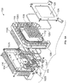
- Figure 1a illustrates an exploded view of the enclosure (100) along with a lighting system in accordance with an embodiment of the present disclosure.
- Figure 1b illustrates an isometric view of the enclosure (100) of Figure 1a .
- the enclosure (100) for lighting systems having at least two compartments comprises a first compartment (102A) provided in a first housing (102) and a second compartment (106A) provided in a second housing (106).
- At least one driver (104) is receivable in the first compartment (102A) and is configured to generate a plurality of driving signals.
- At least one light emitting component (108) is receivable in the second compartment (106A) and is configured to receive the plurality of driving signals.
- the first housing (102) is removably secured to the second housing (106), the first compartment (102A) is insulated from the second compartment (106A).
- the enclosure (100) includes a third compartment (102B) provided in the first housing (102), and a plurality of wires (110) receivable in the third compartment (102B).
- a gasket 115 is positioned between third compartment 102B and third apartment cover 126.
- the plurality of wires (110) are connected to the at least one driver (104) and the at least one light emitting component (108), and are configured to carry the plurality of driving signals from the at least one driver (104) to the at least one light emitting component (108).
- the second housing (106) is provided with a glass lens (122) along with reflectors and a lens cover (124), disposed directly below the operative surface of the at least one light emitting component (108), to facilitate the effective illumination of the surrounding region.
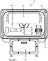
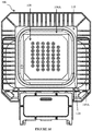
- Figure 1c illustrates a schematic view of the first housing (102) and Figure 1d illustrates a schematic view of the second housing (106) of the enclosure (100) of Figure 1a .
- the at least one light emitting component (108) is an LED matrix
- Conduction occurs when the LED chips, the mechanical structure of the LEDs, the LED mounting structure (such as printed circuit boards) are placed in physical contact with the second housing (106).
- Radiation is the dissipation of heat energy via electromagnetic propagation and much of the radiant energy escapes the LED array (108) through the glass lens (122), which is designed to redirect the radiant energy (visible light in particular) out of the enclosure (100). Further, the radiant energy that does not escape through the glass lens (122) is absorbed within the enclosure (100) and is converted into heat.
- LED Driver is a composite structure in which internal components generate heat. These internal components are encapsulated in epoxy and are further covered by Aluminium case. Heat travels through conduction from internal driver components to epoxy and to the outer Aluminium case. From the outer Aluminium case, heat travels through all three mechanisms of heat transfer.
- the separation of the at least one driver (104) in the first compartment (102A), the at least one light emitting component (108) in the second compartment (106A), and also the plurality of wires (110) in the third compartment (102B) increases the total heat conduction path and reduces the transfer of heat between the at least one driver (104) and the at least one light emitting component (108).
- thermal simulation and testing carried out comparing a single compartment enclosure of conventional lighting systems and the multi-compartment enclosure of the present disclosure shows a 6% reduction in critical temperature T c of the at least one driver (104) (cut-off temperature for driver functioning).
- a comparison between a single compartment enclosure of conventional lighting systems and the multi-compartment enclosure of the present disclosure shows a 15% reduction in the temperature of the at least one light emitting component (108) without the glass lens (122) and a 13% reduction in the temperature of the at least one light emitting component (108) with the glass lens (122).
- a wall (112) (as seen in Figure 1a ) is provided in between the first housing and the second housing (106). The wall (112) is adapted to reduce transfer of heat between the first compartment (102A) and the second compartment (106A).
- the enclosure (100) also includes a first gasket (114) disposed in the first housing (102).
- the first gasket (114) is adapted to provide a thermal break between the at least one driver (104) and the at least one light emitting component (108).
- the enclosure (100) further includes a second gasket (120) disposed in the second housing (106). The second gasket (120) is adapted to provide a thermal insulation to the at least one light emitting component (108).
- a first plurality of fins (116) are configured on the first housing (102).
- the first housing (102) is configured to absorb excess heat generated by the at least one driver (104) and dissipate the excess heat by means of the first plurality of fins (116).
- the second compartment (106A) includes a heat sink (118) provided with a second plurality of fins (118A).
- the heat sink (118) is configured to absorb excess heat generated by the at least one light emitting component (108) and dissipate the excess heat by means of the second plurality of fins (118A).
- the compartmental design of the enclosure (100) provides separate compartments for the components of the lighting system.
- the first compartment (102A) is provided for the at least one driver (104) in the first housing (102), wherein the first housing (102) itself acts as a heat sink for the at least one driver (104).
- the second compartment is provided for the at least one light emitting component (108) in the second housing (106), which includes the heat sink (118) for the at least one light emitting component (108).
- Each of the first plurality of fins (116) and the second plurality of fins (118A) are adapted to dissipate the excess heat generated inside the enclosure (100) into the ambient air surrounding the enclosure (100) by means of convection.
- the spacing between individual fins is optimized for maximum heat reception and dissipation, which facilitates cooling of the components housed in the respective compartments (102A, 106A).
- the first gasket (114) and the second gasket (120) are made of silicone based rubber or low thermally conductive rubber or combinations thereof.
- the first housing (102), the second housing (106), the first plurality of fins (116), the second plurality of fins (118A) are made of a material selected from the group consisting of extruded Aluminium, high-density pressure die-cast material, sand cast Aluminium, cold forged Aluminium, Aluminium alloys with less than 0.4% Copper, and combinations thereof.
- the first gasket (114) and the second gasket (120) are made of a material having a lower thermal conductivity as compared to the first housing (102) and the second housing (106), which allows for them to act as a thermal break.
- the first housing (102) and the second housing (106) are made of sand cast Aluminium, having a thermal conductivity in the range of 110 to 160 W/mK (Watts per meter Kelvin), whereas each of the first gasket (114) and the second gasket (120) are made of silicon rubber having a thermal conductivity of 0.43 W/mK.
- Each of the first gasket (114) and the second gasket (120) are additionally adapted to act as an environmental seal, and prevent ingress of water and other environmental elements into the enclosure (100).
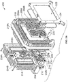
- an enclosure (200) includes two drivers (204A, 204B) received on either operative end of a first compartment (202A) characterized in that the two drivers (204A, 204B) are disposed in the first compartment (202A) in an axially spaced apart configuration.
- the first compartment (202A) is provided in a first housing (202).
- Figure 2a illustrates an exploded view of the enclosure (200) along with a lighting system.
- the enclosure (200) further includes a second compartment (206A), a second housing (206), two light emitting components (208A, 208B), a third compartment (206B), a plurality of wires (210), a wall (212), a first gasket (214), a first plurality of fins (216), a heat sink (218), a second plurality of fins (218A), a second gasket (220), a glass lens (222), a lens cover (224), and a third compartment cover (226), having the same configuration and similar functions as those of the corresponding components of the enclosure (100).
- a gasket 215 is positioned between third compartment 202B and third compartment cover 226.
- each of the first plurality of fins (216) provided on either of the axially opposite sides of the first housing (202), proximal to the two drivers (204A, 204B) disposed in the first compartment (202A), has a profile which facilitates dissipation of the excess heat generated by each of the two drivers (204A, 204B).
- Figure 2b illustrates a cross-sectional view of the enclosure (200) of Figure 2a .
- each of the first plurality of fins (216), provided on either of the axially opposite sides of the first housing (202), includes a raised portion (216a) configured on an operative free end of each fin.
- Figure 2c illustrates a sectional view of one fin from the first plurality of fins (216), provided on either of the axially opposite sides of the first housing (202) of the enclosure (200) of Figure 2a .
- the raised portion (216a) exhibits a higher heat transfer coefficient as compared to the conventional fin (of a perfectly rectangular shape) which accelerates cooling of the two drivers (204A, 204B).
- the raised portion (216a) can be a combination of multiple inclines, or a combination of inclines and curves, or a combination of multiple curves.
- the height of the raised portion (216a) is defined relative to the height above the base fin height (h1) and its location is defined with respect to the outer wall boundary ( OW ) not containing the fin (x).
- the base fin height ( h 1 ) is the height of the fin with respect to the fin base at a location where the raised portion (216a) begins to rise and a maximum raised fin height ( h 2 ) is the height of the raised portion (216a) with respect to the base fin height ( h 1 ).
- x 0 represents the extension of fin beyond the outer wall boundary ( OW ) not containing the fin.
- a protected zone ( PZ ) can be (approximately) defined by
- the two drivers (204A, 204B) are disposed away from the center of the first compartment (202A) and in the proximity of the raised portion (216a) of the first plurality of fins (216), provided on either of the axially opposite sides of the first housing (202), which accelerates cooling of the two drivers (204A, 204B).
- more Lumens can be pumped through the same lighting system disposed in the enclosure (200) as compared to the conventional enclosures.
- Increasing the overall fin area of the second plurality of fins (218A) of the heat sink (218) can further lower the temperature of the two light emitting components (208A, 208B) but at the cost of overall weight of the enclosure (200).
- the lighting system is an LED lighting system wherein the at least one light emitting component (108, 208A, 208B) is an LED array and the at least one driver (104, 204A, 204B) is an LED driver.
- FIG. 1a illustrates a graphical representation of the thickness of the wall (112) provided between the first compartment (102A) and the second compartment (106A), and the consequent hot spot temperature of the LED array (108, 208A, 208B) of the enclosure (100, 200).
- the increase in thickness of the wall (112) increases a conduction area (effective conduction area - EA) for the heat from the LED array (108, 208A, 208B) and reduces the heat spreading resistance.
- the conduction area (EA) of the wall (112, 212) is made greater than the conduction area of the wall connecting the first housing (102, 202) and the second housing (106, 206), thereby reducing the transfer of heat from the first compartment (102A, 202A) to the second compartment (106A, 206A), which further reduces the hot spot temperatures of the LED array (108, 208A, 208B).
- increasing the thickness of the wall (112, 212) from 10 mm to 16 mm reduces the hot spot temperature of the LED array (108, 208A, 208B) by 5%. Further increasing the thickness of the wall (112, 212) can further reduce hot spot temperature, but at the cost of overall weight of the enclosure (100, 200).
- the wall (112, 212) has a relative optimum thickness ranging from 10 mm to 16 mm.
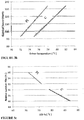
- Figure 3b illustrates a graphical representation of the electric power supplied to the LED driver (104, 204A, 204B) and the consequent rise in temperature of the LED driver (104, 204A, 204B), for both, a lighting system disposed in an enclosure conventionally used in the art (C) and the lighting system disposed in the enclosure (100, 200) of Figures 1a and 2a (PI).
- the LED driver (104, 204A, 204B) functions at a temperature which is cooler by 5% as compared to the driver disposed in the conventional enclosure, thereby improving the efficiency and life of the LED driver (104, 204A, 204B).
- Figure 3c illustrates a graphical representation of the rise in solder point temperature of the LED array (108, 208A, 208B) and the consequent rise in luminous flux produced by the LED array (108, 208A, 208B), for both the lighting system disposed in a conventional enclosure (C) and the lighting system disposed in the enclosure (100, 200) of Figures 1a and 2a (PI).
- the LED array (108, 208A, 208B) functions at a temperature which is cooler by 13% as compared to the LED array disposed in the conventional enclosure, thereby improving the efficiency and life of the at least one light emitting component (108, 208A, 208B).
- a comparative study of the LED lighting systems disposed in conventional enclosures and the enclosure (100, 200) of the present disclosure shows a marked increase in efficiency of the lighting system disposed in the enclosure (100, 200).
- the Table hereinabove illustrates the LED systems operating at Electrical Powers of 93 Watts and 134 Watts and the consequent operating values of the following parameters of the LED lighting systems: LED driver temperature, Heat Sink temperature, LED temperature, and Lumen Variation.
- the table also provides the percentage variation in the aforementioned parameters.
- the Lumen Variation for both LED systems, operating at different electrical power shows a 3% increase when used in the enclosure (100, 200) of the present disclosure.
- the decrease in the LED driver temperatures (4% and 5%), the heat sink temperatures (10% and 13%) and the LED array temperatures (10% and 13%) is significant, thereby increasing the life of each of the components.
- the wall (112, 212) can be replaced with thermal management components selected from the group consisting of heat pipes, graphite sheets, copper pads, and combinations thereof.
- thermal management components selected from the group consisting of heat pipes, graphite sheets, copper pads, and combinations thereof.
- shape, and size of each of the first plurality of fins (116, 216) and the second plurality of fins (118A, 218A) can be optimized to adapt to varying heat dissipation requirements of the at least one driver (104, 204A, 204B) and the at least one light emitting component (108, 208A, 208B).
- the various embodiments of the enclosure (100, 200) as discussed herein above provide for various lighting emitting components to be used with increased efficiency and reliability. Further, the enclosure (100, 200) of the present disclosure also provides ingress protection against environmental elements affecting the operation of lighting systems.
Claims (11)
- Enceinte pour systèmes d'éclairage (100, 200), ladite enceinte comprenant :i. un premier compartiment (102A, 202A) prévu dans un premier boîtier (102, 202) ;ii. au moins un dispositif d'entraînement (104, 204A, 204B) pouvant être reçu dans ledit premier compartiment (102A, 202A) et configuré pour générer une pluralité de signaux d'entraînement ;iii. un deuxième compartiment (106A, 206A) prévu dans un second boîtier (106, 206) ; etiv. au moins un composant électroluminescent (108, 206A, 208B) pouvant être reçu dans ledit deuxième compartiment (106A, 206A) et configuré pour recevoir ladite pluralité de signaux d'entraînement ;
dans laquelle ledit premier boîtier (102, 202) est fixé de manière amovible audit second boîtier (106, 206) ; et ledit premier compartiment (102A, 202A) est isolé dudit deuxième compartiment (106A, 206A) par un premier joint (114, 214) positionné entre le premier boîtier (102, 202) et le second boîtier (106, 206) et adapté pour fournir une rupture thermique entre ledit au moins un dispositif d'entraînement (104, 204A, 204B) et ledit au moins un composant électroluminescent (108, 206A, 208B) ; caractérisé en ce que l'enceinte comprend en outre :v. un troisième compartiment (102B, 202B) prévu dans ledit premier boîtier (102, 202) ; etvi. une pluralité de fils (110, 210) pouvant être reçus dans ledit troisième compartiment (102B, 202B), et connectés audit au moins un dispositif d'entraînement (104, 204A, 204B) et audit au moins un composant électroluminescent (108, 208A, 208B) ;dans laquelle ladite pluralité de fils (110, 210) sont configurés pour transporter ladite pluralité de signaux d'entraînement dudit au moins un dispositif d'entraînement (104, 204A, 204B) audit au moins un composant électroluminescent (108, 208A, 208B) ; etdans laquelle un second joint (115, 215) est positionné entre le troisième compartiment (102B, 202B) et un couvercle (126, 226) du troisième compartiment (102B, 202B). - Enceinte selon la revendication 1, dans laquelle une paroi (112, 212) est prévue entre ledit premier boîtier (102, 202) et ledit second boîtier (106, 206), et ladite paroi (112, 212) est adaptée pour réduire un transfert de chaleur entre ledit premier compartiment (102A, 202A) et ledit deuxième compartiment (106A, 206A).
- Enceinte selon la revendication 1, qui inclut un troisième joint (120, 220) disposé dans ledit second boîtier (106A, 206A) et adapté pour fournir une isolation thermique audit au moins un composant électroluminescent (108, 208A, 208B).
- Enceinte selon la revendication 1, dans laquelle une première pluralité d'ailettes (116, 216) sont configurées sur ledit premier boîtier (102, 202), dans laquelle ledit premier boîtier (102, 202) est configuré pour absorber de la chaleur en excès générée par ledit au moins un dispositif d'entraînement (104, 204A, 204B) et dissiper la chaleur en excès au moyen de ladite première pluralité d'ailettes (116, 216).
- Enceinte selon la revendication 1, dans laquelle ledit deuxième compartiment (106A, 206A) inclut un dissipateur de chaleur (118, 218) pourvu d'une seconde pluralité d'ailettes (118A, 218A), dans laquelle ledit dissipateur de chaleur (118, 218) est configuré pour absorber de la chaleur en excès générée par ledit au moins un composant électroluminescent (108, 208A, 208B) et dissiper la chaleur en excès au moyen de ladite seconde pluralité d'ailettes (118A, 218A).
- Enceinte selon la revendication 1, dans laquelle ledit premier joint (114, 214) et ledit second joint (115, 215) sont réalisés en caoutchouc à base de silicone ou de caoutchouc faiblement thermoconducteur ou de combinaisons de ceux-ci.
- Enceinte selon la revendication 6, dans laquelle ledit premier boîtier (102, 202), ledit second boîtier (106, 206), ladite première pluralité d'ailettes (116, 216) et ladite seconde pluralité d'ailettes (118A, 218A) sont réalisés en un matériau choisi dans le groupe consistant en de l'aluminium extrudé, un matériau coulé sous pression à haute densité, de l'aluminium forgé à froid, des alliages d'aluminium avec moins de 0,4 % de cuivre, et des combinaisons de ceux-ci.
- Enceinte selon la revendication 1, qui inclut deux dispositifs d'entraînements (204A, 204B) reçus sur l'une ou l'autre extrémité opérationnelle dudit premier compartiment (102A, 202A), caractérisée en ce que lesdits deux dispositifs d'entraînements sont disposés dans ledit premier compartiment (102A, 202A) dans une configuration espacée axialement.
- Enceinte selon la revendication 8, dans laquelle une première pluralité d'ailettes (116, 216) sont configurées sur ledit premier boîtier (102, 202), dans laquelle ledit premier boîtier (102, 202) est configuré pour absorber de la chaleur en excès générée par ledit au moins un dispositif d'entraînement (104, 204A, 204B) et dissiper la chaleur en excès au moyen de ladite première pluralité d'ailettes (116, 216), et dans laquelle chacune de ladite première pluralité d'ailettes (116, 216) prévues sur l'un ou l'autre des côtés axialement opposés dudit premier boîtier (102, 202), à proximité desdits deux dispositifs d'entraînement (204A, 204B) disposés dans ledit premier compartiment (102A, 202A), présente un profil qui facilite une dissipation de la chaleur en excès générée par chacun desdits deux dispositifs d'entraînements (204A, 204B).
- Enceinte selon la revendication 9, dans laquelle ledit profil de chacune de ladite première pluralité d'ailettes (116, 216), prévues sur l'un ou l'autre des côtés axialement opposés dudit premier boîtier (102, 202), inclut une partie surélevée configurée sur une extrémité libre opérationnelle de chaque ailette.
- Enceinte selon la revendication 2, dans laquelle l'épaisseur de ladite paroi (112, 212) est dans la plage de 10 mm à 16 mm.
Applications Claiming Priority (2)
| Application Number | Priority Date | Filing Date | Title |
|---|---|---|---|
| IN201621022592 | 2016-06-30 | ||
| PCT/IB2017/051193 WO2018002732A1 (fr) | 2016-06-30 | 2017-03-01 | Enceinte pour systèmes d'éclairage |
Publications (3)
| Publication Number | Publication Date |
|---|---|
| EP3479011A1 EP3479011A1 (fr) | 2019-05-08 |
| EP3479011A4 EP3479011A4 (fr) | 2019-12-11 |
| EP3479011B1 true EP3479011B1 (fr) | 2022-01-05 |
Family
ID=60785957
Family Applications (1)
| Application Number | Title | Priority Date | Filing Date |
|---|---|---|---|
| EP17819431.2A Active EP3479011B1 (fr) | 2016-06-30 | 2017-03-01 | Enceinte pour systèmes d'éclairage |
Country Status (4)
| Country | Link |
|---|---|
| US (1) | US10480763B2 (fr) |
| EP (1) | EP3479011B1 (fr) |
| CN (1) | CN109477616B (fr) |
| WO (1) | WO2018002732A1 (fr) |
Families Citing this family (7)
| Publication number | Priority date | Publication date | Assignee | Title |
|---|---|---|---|---|
| US20200056764A1 (en) * | 2018-08-17 | 2020-02-20 | Sportsbeams Lighting, Inc. | Sports light having single multi-function body |
| US11022287B2 (en) * | 2018-09-12 | 2021-06-01 | Appleton Grp Llc | Explosion proof luminaire |
| KR102645102B1 (ko) * | 2018-12-05 | 2024-03-07 | 쑤저우 레킨 세미컨덕터 컴퍼니 리미티드 | 광원 유닛 및 이를 포함하는 용기 |
| CN218102609U (zh) * | 2019-09-17 | 2022-12-20 | 米沃奇电动工具公司 | 充电器、场地灯以及电源适配器组件 |
| CN113819415A (zh) * | 2020-06-15 | 2021-12-21 | 伊顿智能动力有限公司 | 防爆照明设备 |
| US11655974B2 (en) * | 2021-06-11 | 2023-05-23 | Eaton Intelligent Power Limited | Composite fin heat sink |
| CN113885274B (zh) * | 2021-12-06 | 2022-03-08 | 深圳市爱图仕影像器材有限公司 | 一种影视灯 |
Family Cites Families (19)
| Publication number | Priority date | Publication date | Assignee | Title |
|---|---|---|---|---|
| US5174642A (en) | 1992-02-27 | 1992-12-29 | Hollophane Company, Inc. | Remote ballast assembly |
| WO2005073629A1 (fr) * | 2004-01-28 | 2005-08-11 | Tir Systems Ltd. | Luminaire directement visible |
| TWM272681U (en) * | 2005-03-17 | 2005-08-11 | De-Shiang Fang | Indication device for light guide panel |
| JP5436408B2 (ja) * | 2007-04-03 | 2014-03-05 | オスラム ゲーエムベーハー | 半導体光モジュール |
| EP2153115B1 (fr) | 2007-05-04 | 2021-07-07 | Signify Holding B.V. | Montages à base de led et procédés associés pour le contrôle thermique |
| AU2008293539B2 (en) | 2007-08-27 | 2014-06-26 | Dialight Corporation | LED based hazardous location light with versatile mounting configurations |
| US7762690B2 (en) * | 2008-04-18 | 2010-07-27 | Fu Zhun Precision Industry (Shen Zhen) Co., Ltd. | LED lamp having an improved waterproofing structure |
| MX2012011537A (es) * | 2010-04-05 | 2013-01-29 | Cooper Technologies Co | Montajes de iluminación que tienen transferencia de calor direccional controlada. |
| US8764243B2 (en) | 2010-05-11 | 2014-07-01 | Dialight Corporation | Hazardous location lighting fixture with a housing including heatsink fins surrounded by a band |
| CN201757312U (zh) * | 2010-08-24 | 2011-03-09 | 浙江名芯半导体科技有限公司 | 大功率led防爆灯 |
| CN102966856B (zh) | 2010-12-19 | 2015-01-21 | 西安智海电力科技有限公司 | 带防护吊链和凹槽的旋转式光电分离led泛光灯 |
| MX2013011293A (es) * | 2011-04-01 | 2013-10-30 | Cooper Technologies Co | Proyector de diodo emisor de luz (led). |
| USD693501S1 (en) | 2011-11-22 | 2013-11-12 | Excelitas Technologies Corp. | LED based hazardous area flood light |
| US8950907B2 (en) * | 2012-06-08 | 2015-02-10 | Level Solutions, LLC | Convertible lighting fixture for multiple light sources |
| US20140268729A1 (en) | 2013-03-14 | 2014-09-18 | Lsi Industries, Inc. | Luminaires and luminaire mounting structures |
| CN103557449B (zh) | 2013-10-12 | 2015-09-23 | 王丽娜 | 一种led灯具 |
| US9383090B2 (en) * | 2014-01-10 | 2016-07-05 | Cooper Technologies Company | Floodlights with multi-path cooling |
| WO2015182884A1 (fr) * | 2014-05-29 | 2015-12-03 | 주식회사 포스코엘이디 | Dispositif optique d'éclairage à semi-conducteur |
| WO2015187460A1 (fr) * | 2014-06-02 | 2015-12-10 | Cooper Technologies Company | Système d'éclairage à dissipation thermique |
-
2017
- 2017-03-01 CN CN201780041334.5A patent/CN109477616B/zh active Active
- 2017-03-01 EP EP17819431.2A patent/EP3479011B1/fr active Active
- 2017-03-01 WO PCT/IB2017/051193 patent/WO2018002732A1/fr unknown
- 2017-03-03 US US15/449,309 patent/US10480763B2/en active Active
Also Published As
| Publication number | Publication date |
|---|---|
| CN109477616A (zh) | 2019-03-15 |
| CN109477616B (zh) | 2021-06-25 |
| US10480763B2 (en) | 2019-11-19 |
| WO2018002732A1 (fr) | 2018-01-04 |
| US20180003370A1 (en) | 2018-01-04 |
| EP3479011A1 (fr) | 2019-05-08 |
| EP3479011A4 (fr) | 2019-12-11 |
Similar Documents
| Publication | Publication Date | Title |
|---|---|---|
| EP3479011B1 (fr) | Enceinte pour systèmes d'éclairage | |
| US7699501B2 (en) | LED illuminating device and light engine thereof | |
| US8334640B2 (en) | Turbulent flow cooling for electronic ballast | |
| JP5101578B2 (ja) | 発光ダイオード照明装置 | |
| US7607802B2 (en) | LED lamp instantly dissipating heat as effected by multiple-layer substrates | |
| EP2025998B1 (fr) | Structure de refroidissement pour lampadaire utilisant une diode luminescente | |
| US10168041B2 (en) | Light fixture | |
| US7982225B2 (en) | Heat dissipation device for LED chips | |
| US20130155699A1 (en) | Thermal trim for luminaire | |
| US20070090737A1 (en) | Light-emitting diode assembly and method of fabrication | |
| US20090095448A1 (en) | Heat dissipation device for led chips | |
| US20090052187A1 (en) | Heat-Dissipating Lighting System | |
| JP2014135350A (ja) | ヒートシンク | |
| KR101997669B1 (ko) | 방열구조체 일체형 pcb가 구비된 led 모듈 및 그 제조방법 | |
| JP5331511B2 (ja) | Led照明器具 | |
| CN101740678A (zh) | 固态发光元件及光源模组 | |
| EP2548224B1 (fr) | Ensemble de refroidissement pour refroidir un composant produisant de la chaleur | |
| KR100932430B1 (ko) | Led를 이용한 등기구용 방열장치 | |
| KR20100080887A (ko) | 엘이디 램프의 이중구조 방열판 | |
| KR101179923B1 (ko) | 엘이디 램프의 이중구조 방열판 | |
| RU2768510C1 (ru) | Светодиодный светильник с конвекционным охлаждением | |
| CN205002077U (zh) | 一种led模组的散热结构 | |
| AU2016366819B2 (en) | Improved downlight | |
| KR101544007B1 (ko) | Led조명등 | |
| US20200158321A1 (en) | Lighting system with deformable heat bridge |
Legal Events
| Date | Code | Title | Description |
|---|---|---|---|
| STAA | Information on the status of an ep patent application or granted ep patent |
Free format text: STATUS: THE INTERNATIONAL PUBLICATION HAS BEEN MADE |
|
| PUAI | Public reference made under article 153(3) epc to a published international application that has entered the european phase |
Free format text: ORIGINAL CODE: 0009012 |
|
| STAA | Information on the status of an ep patent application or granted ep patent |
Free format text: STATUS: REQUEST FOR EXAMINATION WAS MADE |
|
| STAA | Information on the status of an ep patent application or granted ep patent |
Free format text: STATUS: REQUEST FOR EXAMINATION WAS MADE |
|
| 17P | Request for examination filed |
Effective date: 20190125 |
|
| AK | Designated contracting states |
Kind code of ref document: A1 Designated state(s): AL AT BE BG CH CY CZ DE DK EE ES FI FR GB GR HR HU IE IS IT LI LT LU LV MC MK MT NL NO PL PT RO RS SE SI SK SM TR |
|
| AX | Request for extension of the european patent |
Extension state: BA ME |
|
| DAV | Request for validation of the european patent (deleted) | ||
| DAX | Request for extension of the european patent (deleted) | ||
| A4 | Supplementary search report drawn up and despatched |
Effective date: 20191111 |
|
| RIC1 | Information provided on ipc code assigned before grant |
Ipc: F21V 29/507 20150101ALN20191105BHEP Ipc: F21V 29/76 20150101ALI20191105BHEP Ipc: F21V 15/01 20060101AFI20191105BHEP Ipc: F21V 29/89 20150101ALN20191105BHEP Ipc: F21V 31/00 20060101ALN20191105BHEP Ipc: F21V 29/508 20150101ALI20191105BHEP Ipc: F21V 23/00 20150101ALI20191105BHEP Ipc: F21Y 105/16 20160101ALN20191105BHEP Ipc: F21Y 115/10 20160101ALN20191105BHEP |
|
| STAA | Information on the status of an ep patent application or granted ep patent |
Free format text: STATUS: THE APPLICATION IS DEEMED TO BE WITHDRAWN |
|
| RIN1 | Information on inventor provided before grant (corrected) |
Inventor name: DEVAPPA, HARSHA NARASIMHARAJPUR Inventor name: MANDLEKAR, KARAN CHANDRAKANT Inventor name: GRAFF, E. TIMOTHY Inventor name: KUMAR, SUMIT |
|
| STAA | Information on the status of an ep patent application or granted ep patent |
Free format text: STATUS: REQUEST FOR EXAMINATION WAS MADE |
|
| 18D | Application deemed to be withdrawn |
Effective date: 20200609 |
|
| D18D | Application deemed to be withdrawn (deleted) | ||
| STAA | Information on the status of an ep patent application or granted ep patent |
Free format text: STATUS: EXAMINATION IS IN PROGRESS |
|
| 17Q | First examination report despatched |
Effective date: 20210211 |
|
| REG | Reference to a national code |
Ref country code: DE Ref legal event code: R079 Ref document number: 602017051986 Country of ref document: DE Free format text: PREVIOUS MAIN CLASS: F21L0002000000 Ipc: F21V0015010000 |
|
| RIC1 | Information provided on ipc code assigned before grant |
Ipc: F21V 29/89 20150101ALN20210816BHEP Ipc: F21Y 105/16 20160101ALN20210816BHEP Ipc: F21Y 115/10 20160101ALN20210816BHEP Ipc: F21V 29/507 20150101ALN20210816BHEP Ipc: F21V 31/00 20060101ALN20210816BHEP Ipc: F21V 29/508 20150101ALI20210816BHEP Ipc: F21V 29/76 20150101ALI20210816BHEP Ipc: F21V 23/00 20150101ALI20210816BHEP Ipc: F21V 15/01 20060101AFI20210816BHEP |
|
| GRAP | Despatch of communication of intention to grant a patent |
Free format text: ORIGINAL CODE: EPIDOSNIGR1 |
|
| STAA | Information on the status of an ep patent application or granted ep patent |
Free format text: STATUS: GRANT OF PATENT IS INTENDED |
|
| RIC1 | Information provided on ipc code assigned before grant |
Ipc: F21V 29/89 20150101ALN20210908BHEP Ipc: F21Y 105/16 20160101ALN20210908BHEP Ipc: F21Y 115/10 20160101ALN20210908BHEP Ipc: F21V 29/507 20150101ALN20210908BHEP Ipc: F21V 31/00 20060101ALN20210908BHEP Ipc: F21V 29/508 20150101ALI20210908BHEP Ipc: F21V 29/76 20150101ALI20210908BHEP Ipc: F21V 23/00 20150101ALI20210908BHEP Ipc: F21V 15/01 20060101AFI20210908BHEP |
|
| INTG | Intention to grant announced |
Effective date: 20211004 |
|
| GRAS | Grant fee paid |
Free format text: ORIGINAL CODE: EPIDOSNIGR3 |
|
| GRAA | (expected) grant |
Free format text: ORIGINAL CODE: 0009210 |
|
| STAA | Information on the status of an ep patent application or granted ep patent |
Free format text: STATUS: THE PATENT HAS BEEN GRANTED |
|
| AK | Designated contracting states |
Kind code of ref document: B1 Designated state(s): AL AT BE BG CH CY CZ DE DK EE ES FI FR GB GR HR HU IE IS IT LI LT LU LV MC MK MT NL NO PL PT RO RS SE SI SK SM TR |
|
| REG | Reference to a national code |
Ref country code: CH Ref legal event code: EP |
|
| REG | Reference to a national code |
Ref country code: AT Ref legal event code: REF Ref document number: 1460914 Country of ref document: AT Kind code of ref document: T Effective date: 20220115 |
|
| REG | Reference to a national code |
Ref country code: DE Ref legal event code: R096 Ref document number: 602017051986 Country of ref document: DE |
|
| REG | Reference to a national code |
Ref country code: IE Ref legal event code: FG4D |
|
| REG | Reference to a national code |
Ref country code: LT Ref legal event code: MG9D |
|
| REG | Reference to a national code |
Ref country code: NL Ref legal event code: MP Effective date: 20220105 |
|
| REG | Reference to a national code |
Ref country code: AT Ref legal event code: MK05 Ref document number: 1460914 Country of ref document: AT Kind code of ref document: T Effective date: 20220105 |
|
| PG25 | Lapsed in a contracting state [announced via postgrant information from national office to epo] |
Ref country code: NL Free format text: LAPSE BECAUSE OF FAILURE TO SUBMIT A TRANSLATION OF THE DESCRIPTION OR TO PAY THE FEE WITHIN THE PRESCRIBED TIME-LIMIT Effective date: 20220105 |
|
| PG25 | Lapsed in a contracting state [announced via postgrant information from national office to epo] |
Ref country code: SE Free format text: LAPSE BECAUSE OF FAILURE TO SUBMIT A TRANSLATION OF THE DESCRIPTION OR TO PAY THE FEE WITHIN THE PRESCRIBED TIME-LIMIT Effective date: 20220105 Ref country code: RS Free format text: LAPSE BECAUSE OF FAILURE TO SUBMIT A TRANSLATION OF THE DESCRIPTION OR TO PAY THE FEE WITHIN THE PRESCRIBED TIME-LIMIT Effective date: 20220105 Ref country code: PT Free format text: LAPSE BECAUSE OF FAILURE TO SUBMIT A TRANSLATION OF THE DESCRIPTION OR TO PAY THE FEE WITHIN THE PRESCRIBED TIME-LIMIT Effective date: 20220505 Ref country code: NO Free format text: LAPSE BECAUSE OF FAILURE TO SUBMIT A TRANSLATION OF THE DESCRIPTION OR TO PAY THE FEE WITHIN THE PRESCRIBED TIME-LIMIT Effective date: 20220405 Ref country code: LT Free format text: LAPSE BECAUSE OF FAILURE TO SUBMIT A TRANSLATION OF THE DESCRIPTION OR TO PAY THE FEE WITHIN THE PRESCRIBED TIME-LIMIT Effective date: 20220105 Ref country code: HR Free format text: LAPSE BECAUSE OF FAILURE TO SUBMIT A TRANSLATION OF THE DESCRIPTION OR TO PAY THE FEE WITHIN THE PRESCRIBED TIME-LIMIT Effective date: 20220105 Ref country code: ES Free format text: LAPSE BECAUSE OF FAILURE TO SUBMIT A TRANSLATION OF THE DESCRIPTION OR TO PAY THE FEE WITHIN THE PRESCRIBED TIME-LIMIT Effective date: 20220105 Ref country code: BG Free format text: LAPSE BECAUSE OF FAILURE TO SUBMIT A TRANSLATION OF THE DESCRIPTION OR TO PAY THE FEE WITHIN THE PRESCRIBED TIME-LIMIT Effective date: 20220405 |
|
| PG25 | Lapsed in a contracting state [announced via postgrant information from national office to epo] |
Ref country code: PL Free format text: LAPSE BECAUSE OF FAILURE TO SUBMIT A TRANSLATION OF THE DESCRIPTION OR TO PAY THE FEE WITHIN THE PRESCRIBED TIME-LIMIT Effective date: 20220105 Ref country code: LV Free format text: LAPSE BECAUSE OF FAILURE TO SUBMIT A TRANSLATION OF THE DESCRIPTION OR TO PAY THE FEE WITHIN THE PRESCRIBED TIME-LIMIT Effective date: 20220105 Ref country code: GR Free format text: LAPSE BECAUSE OF FAILURE TO SUBMIT A TRANSLATION OF THE DESCRIPTION OR TO PAY THE FEE WITHIN THE PRESCRIBED TIME-LIMIT Effective date: 20220406 Ref country code: FI Free format text: LAPSE BECAUSE OF FAILURE TO SUBMIT A TRANSLATION OF THE DESCRIPTION OR TO PAY THE FEE WITHIN THE PRESCRIBED TIME-LIMIT Effective date: 20220105 Ref country code: AT Free format text: LAPSE BECAUSE OF FAILURE TO SUBMIT A TRANSLATION OF THE DESCRIPTION OR TO PAY THE FEE WITHIN THE PRESCRIBED TIME-LIMIT Effective date: 20220105 |
|
| PG25 | Lapsed in a contracting state [announced via postgrant information from national office to epo] |
Ref country code: IS Free format text: LAPSE BECAUSE OF FAILURE TO SUBMIT A TRANSLATION OF THE DESCRIPTION OR TO PAY THE FEE WITHIN THE PRESCRIBED TIME-LIMIT Effective date: 20220505 |
|
| REG | Reference to a national code |
Ref country code: DE Ref legal event code: R097 Ref document number: 602017051986 Country of ref document: DE |
|
| PG25 | Lapsed in a contracting state [announced via postgrant information from national office to epo] |
Ref country code: SM Free format text: LAPSE BECAUSE OF FAILURE TO SUBMIT A TRANSLATION OF THE DESCRIPTION OR TO PAY THE FEE WITHIN THE PRESCRIBED TIME-LIMIT Effective date: 20220105 Ref country code: SK Free format text: LAPSE BECAUSE OF FAILURE TO SUBMIT A TRANSLATION OF THE DESCRIPTION OR TO PAY THE FEE WITHIN THE PRESCRIBED TIME-LIMIT Effective date: 20220105 Ref country code: RO Free format text: LAPSE BECAUSE OF FAILURE TO SUBMIT A TRANSLATION OF THE DESCRIPTION OR TO PAY THE FEE WITHIN THE PRESCRIBED TIME-LIMIT Effective date: 20220105 Ref country code: MC Free format text: LAPSE BECAUSE OF FAILURE TO SUBMIT A TRANSLATION OF THE DESCRIPTION OR TO PAY THE FEE WITHIN THE PRESCRIBED TIME-LIMIT Effective date: 20220105 Ref country code: EE Free format text: LAPSE BECAUSE OF FAILURE TO SUBMIT A TRANSLATION OF THE DESCRIPTION OR TO PAY THE FEE WITHIN THE PRESCRIBED TIME-LIMIT Effective date: 20220105 Ref country code: DK Free format text: LAPSE BECAUSE OF FAILURE TO SUBMIT A TRANSLATION OF THE DESCRIPTION OR TO PAY THE FEE WITHIN THE PRESCRIBED TIME-LIMIT Effective date: 20220105 Ref country code: CZ Free format text: LAPSE BECAUSE OF FAILURE TO SUBMIT A TRANSLATION OF THE DESCRIPTION OR TO PAY THE FEE WITHIN THE PRESCRIBED TIME-LIMIT Effective date: 20220105 |
|
| REG | Reference to a national code |
Ref country code: CH Ref legal event code: PL |
|
| PLBE | No opposition filed within time limit |
Free format text: ORIGINAL CODE: 0009261 |
|
| STAA | Information on the status of an ep patent application or granted ep patent |
Free format text: STATUS: NO OPPOSITION FILED WITHIN TIME LIMIT |
|
| PG25 | Lapsed in a contracting state [announced via postgrant information from national office to epo] |
Ref country code: AL Free format text: LAPSE BECAUSE OF FAILURE TO SUBMIT A TRANSLATION OF THE DESCRIPTION OR TO PAY THE FEE WITHIN THE PRESCRIBED TIME-LIMIT Effective date: 20220105 |
|
| REG | Reference to a national code |
Ref country code: BE Ref legal event code: MM Effective date: 20220331 |
|
| 26N | No opposition filed |
Effective date: 20221006 |
|
| PG25 | Lapsed in a contracting state [announced via postgrant information from national office to epo] |
Ref country code: LU Free format text: LAPSE BECAUSE OF NON-PAYMENT OF DUE FEES Effective date: 20220301 Ref country code: LI Free format text: LAPSE BECAUSE OF NON-PAYMENT OF DUE FEES Effective date: 20220331 Ref country code: IE Free format text: LAPSE BECAUSE OF NON-PAYMENT OF DUE FEES Effective date: 20220301 Ref country code: CH Free format text: LAPSE BECAUSE OF NON-PAYMENT OF DUE FEES Effective date: 20220331 |
|
| PG25 | Lapsed in a contracting state [announced via postgrant information from national office to epo] |
Ref country code: SI Free format text: LAPSE BECAUSE OF FAILURE TO SUBMIT A TRANSLATION OF THE DESCRIPTION OR TO PAY THE FEE WITHIN THE PRESCRIBED TIME-LIMIT Effective date: 20220105 Ref country code: BE Free format text: LAPSE BECAUSE OF NON-PAYMENT OF DUE FEES Effective date: 20220331 |
|
| PGFP | Annual fee paid to national office [announced via postgrant information from national office to epo] |
Ref country code: FR Payment date: 20230222 Year of fee payment: 7 |
|
| PGFP | Annual fee paid to national office [announced via postgrant information from national office to epo] |
Ref country code: GB Payment date: 20230222 Year of fee payment: 7 Ref country code: DE Payment date: 20230221 Year of fee payment: 7 |
|
| P01 | Opt-out of the competence of the unified patent court (upc) registered |
Effective date: 20230522 |
|
| PG25 | Lapsed in a contracting state [announced via postgrant information from national office to epo] |
Ref country code: IT Free format text: LAPSE BECAUSE OF FAILURE TO SUBMIT A TRANSLATION OF THE DESCRIPTION OR TO PAY THE FEE WITHIN THE PRESCRIBED TIME-LIMIT Effective date: 20220105 |
|
| PG25 | Lapsed in a contracting state [announced via postgrant information from national office to epo] |
Ref country code: HU Free format text: LAPSE BECAUSE OF FAILURE TO SUBMIT A TRANSLATION OF THE DESCRIPTION OR TO PAY THE FEE WITHIN THE PRESCRIBED TIME-LIMIT; INVALID AB INITIO Effective date: 20170301 |
|
| PG25 | Lapsed in a contracting state [announced via postgrant information from national office to epo] |
Ref country code: MK Free format text: LAPSE BECAUSE OF FAILURE TO SUBMIT A TRANSLATION OF THE DESCRIPTION OR TO PAY THE FEE WITHIN THE PRESCRIBED TIME-LIMIT Effective date: 20220105 Ref country code: CY Free format text: LAPSE BECAUSE OF FAILURE TO SUBMIT A TRANSLATION OF THE DESCRIPTION OR TO PAY THE FEE WITHIN THE PRESCRIBED TIME-LIMIT Effective date: 20220105 |
|
| PGFP | Annual fee paid to national office [announced via postgrant information from national office to epo] |
Ref country code: DE Payment date: 20240220 Year of fee payment: 8 Ref country code: GB Payment date: 20240220 Year of fee payment: 8 |