EP3478352B1 - Method of generating a configuration for a customized headgear - Google Patents
Method of generating a configuration for a customized headgear Download PDFInfo
- Publication number
- EP3478352B1 EP3478352B1 EP17739502.7A EP17739502A EP3478352B1 EP 3478352 B1 EP3478352 B1 EP 3478352B1 EP 17739502 A EP17739502 A EP 17739502A EP 3478352 B1 EP3478352 B1 EP 3478352B1
- Authority
- EP
- European Patent Office
- Prior art keywords
- physical features
- straps
- pair
- strap
- patient
- Prior art date
- Legal status (The legal status is an assumption and is not a legal conclusion. Google has not performed a legal analysis and makes no representation as to the accuracy of the status listed.)
- Active
Links
Images


Classifications
-
- A—HUMAN NECESSITIES
- A61—MEDICAL OR VETERINARY SCIENCE; HYGIENE
- A61M—DEVICES FOR INTRODUCING MEDIA INTO, OR ONTO, THE BODY; DEVICES FOR TRANSDUCING BODY MEDIA OR FOR TAKING MEDIA FROM THE BODY; DEVICES FOR PRODUCING OR ENDING SLEEP OR STUPOR
- A61M16/00—Devices for influencing the respiratory system of patients by gas treatment, e.g. ventilators; Tracheal tubes
- A61M16/06—Respiratory or anaesthetic masks
- A61M16/0605—Means for improving the adaptation of the mask to the patient
-
- A—HUMAN NECESSITIES
- A61—MEDICAL OR VETERINARY SCIENCE; HYGIENE
- A61M—DEVICES FOR INTRODUCING MEDIA INTO, OR ONTO, THE BODY; DEVICES FOR TRANSDUCING BODY MEDIA OR FOR TAKING MEDIA FROM THE BODY; DEVICES FOR PRODUCING OR ENDING SLEEP OR STUPOR
- A61M16/00—Devices for influencing the respiratory system of patients by gas treatment, e.g. ventilators; Tracheal tubes
- A61M16/06—Respiratory or anaesthetic masks
- A61M16/0683—Holding devices therefor
- A61M16/0694—Chin straps
-
- A—HUMAN NECESSITIES
- A62—LIFE-SAVING; FIRE-FIGHTING
- A62B—DEVICES, APPARATUS OR METHODS FOR LIFE-SAVING
- A62B18/00—Breathing masks or helmets, e.g. affording protection against chemical agents or for use at high altitudes or incorporating a pump or compressor for reducing the inhalation effort
- A62B18/04—Gas helmets
- A62B18/045—Gas helmets with fans for delivering air for breathing mounted in or on the helmet
-
- G—PHYSICS
- G06—COMPUTING OR CALCULATING; COUNTING
- G06F—ELECTRIC DIGITAL DATA PROCESSING
- G06F30/00—Computer-aided design [CAD]
-
- A—HUMAN NECESSITIES
- A61—MEDICAL OR VETERINARY SCIENCE; HYGIENE
- A61M—DEVICES FOR INTRODUCING MEDIA INTO, OR ONTO, THE BODY; DEVICES FOR TRANSDUCING BODY MEDIA OR FOR TAKING MEDIA FROM THE BODY; DEVICES FOR PRODUCING OR ENDING SLEEP OR STUPOR
- A61M16/00—Devices for influencing the respiratory system of patients by gas treatment, e.g. ventilators; Tracheal tubes
- A61M16/06—Respiratory or anaesthetic masks
- A61M2016/0661—Respiratory or anaesthetic masks with customised shape
-
- A—HUMAN NECESSITIES
- A61—MEDICAL OR VETERINARY SCIENCE; HYGIENE
- A61M—DEVICES FOR INTRODUCING MEDIA INTO, OR ONTO, THE BODY; DEVICES FOR TRANSDUCING BODY MEDIA OR FOR TAKING MEDIA FROM THE BODY; DEVICES FOR PRODUCING OR ENDING SLEEP OR STUPOR
- A61M2207/00—Methods of manufacture, assembly or production
- A61M2207/10—Device therefor
-
- G—PHYSICS
- G06—COMPUTING OR CALCULATING; COUNTING
- G06F—ELECTRIC DIGITAL DATA PROCESSING
- G06F2119/00—Details relating to the type or aim of the analysis or the optimisation
- G06F2119/18—Manufacturability analysis or optimisation for manufacturability
Definitions
- the present invention relates to patient interface devices for transporting a gas to and/or from an airway of a patient and, in particular, to a method of generating a configuration for a headgear that is customized for a particular patient.
- CPAP continuous positive airway pressure
- VSA obstructive sleep apnea
- Non-invasive ventilation and pressure support therapies involve the placement of a patient interface device including a mask component on the face of a patient.
- the mask component may be, without limitation, a nasal mask that covers the patient's nose, a nasal cushion that rests beneath the patient's nose (such as a "pillows" style nasal cushion having nasal prongs that are received within the patient's nostrils or a "cradle” style nasal cushion that rests beneath and covers the patient's nostrils), a nasal/oral mask that covers the nose and mouth, or a full face mask that covers the patient's face.
- the patient interface device interfaces the ventilator or pressure support device with the airway of the patient so that a flow of breathing gas can be delivered from the pressure/flow generating device to the airway of the patient. It is known to maintain such devices on the face of a wearer by a headgear having one or more straps adapted to fit over/around the patient's head.
- the international patent application WO2016/000040 discloses a method of manufacturing a patient interface for sealed delivery of a flow of air at a continuously positive pressure with respect to ambient air pressure to an entrance to the patient's airways which includes collecting anthropometric data of a patient's face. Anticipated considerations are identified from the collected anthropometric data during use of the patient interface. The collected anthropometric data is processed to provide a transformed data set based on the anticipated considerations, the transformed data set corresponding to at least one customised patient interface component. At least one patient interface component is modelled based on the transformed data set.
- headgear Due to the variability of shapes and sizes of the heads of patients, numerous types and configurations of headgear are available for selection by a professional to suit the needs of any given patient. However, most headgear is intended to be worn by a large number of people having different head shapes and sizes, and thus any given headgear typically is not necessarily customized for any particular patient and rather is intended to fit a variety of patents. While some success has been achieved in selecting pre-designed headgear for patients and achieving a reasonable fit with such patients, the fit is still, on the whole, at best only what can be reasonable achieved with a headgear that is intended for use with a range of head sizes and shapes, which is not an optimum fit. Improvements thus would be desirable.
- an object of the present invention to provide a method of generating a configuration for a headgear that is customized for a particular patient and that overcomes the shortcomings of conventional methods.
- This object is achieved according to one embodiment of the present invention by providing an improved method of generating a configuration for a headgear that is customized for a particular patient who is in need of respiratory therapy, the headgear having a plurality of physical features and being usable with a mask component that supplies a flow of breathing gas to the patient's airways.
- the method comprises receiving one or more parameters pertaining to the patient's head, subjecting at least some of the parameters to one or more algorithms to determine at least one of a length of a physical feature of the plurality of physical features and an angle between a pair of physical features of the plurality of physical features, generating an outline of at least a portion of a body which, when formed, is usable to assemble therefrom at least a portion of the headgear, the outline including the at least one of a length of a physical feature of the plurality of physical features and an angle between a pair of physical features of the plurality of physical features, and outputting a pattern that is visible and that comprises the outline, the pattern being usable to enable the formation of the at least portion of the body from at least a first sheet of at least a first material.
- the word "unitary” means a component is created as a single piece or unit. That is, a component that includes pieces that are created separately and then coupled together as a unit is not a “unitary” component or body.
- the statement that two or more parts or components "engage” one another shall mean that the parts exert a force against one another either directly or through one or more intermediate parts or components.
- the term “number” shall mean one or an integer greater than one (i.e., a plurality).
- FIG. 1 An improved headgear 4 that results from an improved method in accordance with the disclosed and claimed concept is depicted in FIG. 1 .
- Headgear 4 is depicted as being connected with a mask component 8 that is connected in fluid communication with a supply of breathing gas 12. It is understood that the supply of breathing gas 12 provides a flow of breathing gas that is supplied via mask component 8 to a patient 16 ( FIG. 2 ) who is in need of respiratory therapy. It is understood that mask component 8 is in fluid communication with the airways of patient 16 and that headgear 4 secures the mask components on patient 16.
- headgear 4 is made in accordance with an improved method that is in accordance with the disclosed and claimed concept whereby headgear 4 is customized to suit the particular patient 16 in order to advantageously provide an improved fit.
- Headgear 4 can be said to include a plurality of physical features 20 that can be said to comprise a base 24 and a strap apparatus 28 that extends from and is connected with base 24.
- Strap apparatus 28 can be said to include a parietal strap 32, a left temporal strap 36, and a right temporal strap 40.
- Strap apparatus 28 further includes a left occipital strap 44 having a left temporal attachment point 48 and a left parietal attachment point 52.
- strap apparatus 28 includes a right occipital strap 56 having a right temporal attachment point 60 and a right parietal attachment point 64.
- strap apparatus 28 includes a left chin strap 68 that is connected with a left chin attachment point 72 and further includes a right chin strap 76 that is connected with a right chin attachment point 80.
- parietal strap 32 extends across the parietal region of patient 16, that left and right temporal straps 36 and 40 extend across the temporal region of patent 16, and that left and right occipital straps 44 and 56 extend across the occipital region of patient 16 when headgear 4 is installed on patient 16.
- left and right chin straps 68 and 76 extend between base 24 and the chin region of patient 16 when headgear 4 is installed on patient 16.
- Patient 16 has a head 84 and a pair of ears 92 that include a pair of earlobes such as depicted generally in FIG. 2 , and head 84 has a size and shape that is specific to patient 16.
- An improved method that is in accordance with the disclosed and claimed concept and that will be described in greater detail below involves receiving from patient 16 a number of parameters that pertain to head 84.
- the parameters include an upper head circumference (UHC) 88 that is measured around the head circumference between the forehead and the parietal region, and which is measured above ears 92.
- the parameters further include a lower head circumference (LHC) that is measured between the tip of the nose 100 and the occipital region, and which is measured below earlobes 104.
- the parameters further include an earlobe to earlobe length (E2E) 108 measured between earlobes 104 across the crown of head 84. Additionally, the parameters include a distance (D) 112 that is measured between upper head circumference 88 and lower head circumference 96.
- E2E earlobe to earlobe length
- D distance
- patient 16 can himself or herself measure the parameters of head 84, although the parameters can be measured by a healthcare professional or other individual. This measurement can be made using any suitable technique or measuring device.
- the parameters once measured, are then input into a computer 116, such as is depicted in a schematic fashion in FIG. 4 .
- Computer 116 is a general purpose computer, although it could be purpose built without departing from the present concept.
- Computer 116 can be said to include a processor apparatus 120, an input apparatus 124 that provides input signals to processor apparatus 120, and an output apparatus 128 that receives output signals from processor apparatus 120.
- Processor apparatus 120 can be said to include a processor 132 and to further include a storage 136 having one or more routines 140 stored therein.
- Processor 132 can be any of a wide variety of processors, including microprocessors, and the like.
- Storage 136 can be any of a wide variety of storage systems and can include RAM, ROM, EPROM, FLASH, and the like without limitation.
- Routines 140 are in the form of instructions that are stored in storage 136 and that are executable by processor 132 to cause computer 116 to perform various operations such as are set forth herein. It is expressly noted that computer 116 could be, in whole or in part, cloud-based and is not limited to physical hardware that is situated at any given physical location.
- Input apparatus 124 can be said to include a keyboard 144 and any of a variety of other input devices such as a mouse, a touchpad, a barcode reader, and the like, without limitation.
- Output apparatus 128 is depicted in FIG. 4 as including a visual display 148 and a printer 152 among other output devices.
- the aforementioned parameters are uploaded to computer 116 via input apparatus 124 or otherwise, and the parameters are then subjected to one or more algorithms that are embodied in routines 140 being executed by processor 132.
- Such subjecting of the parameters to the various algorithms, tables, or other techniques or combination of techniques enables computer 116 to determine various lengths of physical features 20, various angles between physical features 20, and other properties and values, which together generate a configuration for headgear 4.
- Routines 140 can be said to together form a model that is used to generate the configuration of headgear 4 in response to the various parameters that are received from patient 16.
- the model also generates from the configuration a pattern 156 that is imprinted onto a sheet of paper 160 ( FIGS. 7 and 8 ) or other substrate by printer 152.
- the sheet of paper 160 that includes pattern 156 can then be overlaid on a sheet of material 162 such as cloth or other appropriate material in order to enable the various components from which headgear 4 will be formed to be cut from sheet of material 162, such as by using scissors or the like, and by following pattern 156.
- Sheet of material 162 in the depicted exemplary embodiment is a sheet of fabric that is of in appropriate configuration and density for formation of headgear 4.
- additional or other sheets of material can be employed to form various parts of headgear 4 without departing from the scope of the present concept.
- FIG. 5 depicts certain elements which, when visually output, will form a pattern 156 such as is shown in FIGS. 7 and 8 .
- Pattern 156 includes an amount of imprinted content 164, much of which is depicted in FIG. 5 , and which, in the depicted exemplary embodiment, includes a first outline 168 that is an outline of a body 172 of headgear 4.
- the model that generates the configuration of headgear 4 from the aforementioned parameters also configures body 172 to include base 24, left and right occipital straps 44 and 56, and left and right chin attachment points 72 and 80.
- first outline 168 By employing first outline 168 to cut from sheet of material 162 body 172, the resulting body 172 that is formed therefrom will include the aforementioned physical features 20 (base 24, left and right occipital straps 44 and 56, and left and right chin attachment points 72 and 80) of headgear 4 as a single piece unitary structure. It is understood that in other embodiments the model could create as body 172 another combination of physical features 20 individually or in any combination that is suitable.
- the exemplary first outline 168 is merely one fashion in which at least a portion of the various components or physical features 20 of headgear 4 can be arranged according to the aforementioned configuration of headgear for that is generated by computer 116, and it is thus understood that variations can be employed without departing from the scope of the instant disclosure.
- the exemplary imprinted content 164 further includes a bill of materials 176 that expressly identifies the other parts and, if applicable, the quantity thereof that should be made, in order to enable headgear 4 to be assembled from such components and from body 172.
- the imprinted content 164 additional includes a second outline 180 that is an outline of parietal strap 32, a third outline 184 that is an outline of left and right temporal straps 36 and 40, and a fourth outline 188 that is an outline of left and right chin straps 68 and 76.
- left and right temporal straps 36 and 40 are mirror images of one another and that left and right chin straps 68 and 76 are likewise mirror images of one another in the depicted exemplary embodiment.
- separate outlines for such straps can be provided rather than simply providing a single outline that is employed for forming a pair of straps therefrom. This might be useful in a scenario where, for instance, left and right temporal straps 36 and 40 might not be mirror images of one another, and/or wherein left and right chin straps 68 and 76 are not mirror images of one another.
- the exemplary imprinted content 164 further includes a fifth outline 192 that is employed in conjunction with a sheet of hook material to generate a plurality of hook attachments 194 that are usable at some of the ends of the straps of strap apparatus 28. That is, hook attachments 194 are affixed to some of the ends of the straps of strap apparatus 28, and hook attachments 194 thereby each enable such an end of a strap to be turned back on itself to enable the hooks of hook attachment 194 to be engaged with corresponding loops that are formed on the corresponding strap, This enables the formation of hook-and-loop attachments or fasteners that enable such straps to be connected with mask component 8.
- the various components that are specified by pattern 156 can be formed out of sheet of material 162 and other sheets of material, as appropriate, in order to form the various components that are specified in bill of materials 176.
- the various components can then be assembled together to form headgear 4. Such assembly may involve sewing together of certain of the various components with one another in a fashion that will be set forth in greater detail below.
- FIG. 3 depicts an exemplary flowchart that describes in general terms how pattern 156 is developed by routines 140 from the aforementioned parameters that pertain to head 84 and that are received from patient 16.
- computer 116 receives from patient 16 one or more of the parameters that pertain to head 84 of patient 16.
- the parameters are then subjected, as at 206, to one or more algorithms tables, or other techniques or combination of techniques that are embodied in routines 140 and the model in order to determine various lengths of physical features 20 and angles between physical features 20, and the like.
- Routines 140 then generate, as at 210, one or more outlines, such as any one or more of first outline 168, second outline 180, third outline 184, fourth outline 188, and fifth outline 192.
- Such outlines when formed from sheet of material 162 and/or other sheets of material or other materials, are usable to assemble at least a portion of headgear 4 according to the configuration that has been generated by routines 140.
- Computer 116 then outputs, as at 214, pattern 156 in a visible form that includes bill of materials 176 and one or more of the aforementioned outlines such as first outline 168, second outline 180 third outline 184, fourth outline 188, and fifth outline 192.
- Such outlines enable body 172 and other of the physical features 20 to be formed from sheet of material 162 and other sheets of material, as appropriate.
- left occipital strap 44 is elongated and can be said to have an axis of elongation 196
- right occipital strap 56 can likewise be said to be elongated and to have an axis of elongation 200
- Left chin strap 68 similarly is elongated and has an axis of elongation 204 that is depicted as extending from left chin attachment point 72
- right chin strap 76 likewise is elongated and has an axis of elongation 208 that is depicted as extending from right chin attachment point 80.
- left temporal strap 36 is elongated and has an axis of elongation 202 that is depicted as extending from left temporal attachment point 48
- right temporal strap 40 is similarly elongated and has an axis of elongation 216 that is depicted as extending from right chin attachment point 60.
- parietal strap 32 is ultimately going to be affixed to the ends of left and right parietal attachment points 52 and 64.
- left and right parietal attachment points 52 and 64 are themselves curved, an end 220 of right parietal attachment point 62 is situated in a particular orientation with respect to axis of elongation 216, and left parietal attachment point 52 is a mirror image thereof.
- left and right temporal straps 36 and 40 are of an exemplary equal temporal length (L1) 224
- left and right chin straps 68 and 76 are of an exemplary equal chin length (L2) 228.
- left and right occipital straps 44 and 56 are of an exemplary equal occipital length (L3) 232
- parietal strap 32 is of a parietal length (L4) 236. While lengths L1, L2, L3, and L4, which are indicated at numerals 224, 228, 232, and 236, respectively, are depicted in FIG. 5 , such lengths need not necessarily be expressly output as part of imprinted content 164 of pattern 156, and rather it is anticipated that such express lengths typically would be absent from pattern 156.
- FIG. 5 further depicts an angle A1 240 as being the angle between the free ends of left and right chin attachment points 72 and 80.
- An angle A2 244 is depicted in FIG. 5 as being the angle between axis of elongation 196 and axis of elongation 200.
- Another angle A4 252 is an angle between end 220 of right parietal attachment point 64 and direction of elongation 216 of right temporal strap 40, which is equal to another angle A4 at the opposite side of body 172 that is not expressly depicted herein for reasons of simplicity.
- Another angle A5 256 is the angle between the aforementioned direction of elongation 216 of right temporal strap 40 and axis of elongation 200.
- Another angle A6 260 is the angle between the aforementioned direction of elongation 216 of right temporal strap 40 and an axis of elongation 222 of right parietal attachment point 64 at it extends from right temporal attachment point 60.
- An additional angle A7 264 is the angle between axis of elongation 200 and axis of elongation 208.
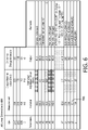
- the interrelationships between the various aforementioned lengths and the various aforementioned angles of the various physical features 20 are set forth in FIG. 6 .
- the model is configured to begin with a nominal value for each of the aforementioned angles and lengths, as is indicated under the heading "Nominal” in FIG. 6 .
- the model is further configured to employ the aforementioned parameters that pertain to head 84, i.e., UHC 88, LHC 96, E2E 108, and D 112, to calculate an Estimated Adjustment Value (EAV) that is applied to the nominal valued in order to adjust the nominal values, as appropriate, to generate corresponding output values, as is indicated under the heading "Output” in FIG. 6 .
- EAV Estimated Adjustment Value
- A1 240, A4 252, A5 256, and A6 260 remain unchanged, although in other embodiments in accordance with the disclosed and claimed concept, they potentially can change depending upon the received parameters and/or depending upon how the model is designed.
- the lengths L1 224, L2 228, L3 232, and L4 236 are calculated based upon the received parameters UHC 88, LHC 96, E2E 108, and D 112 all as indicated in the "Remarks" portion of FIG. 6.
- FIG. 6 thus can be said to depict certain of the algorithms to which the parameters are subjected.
- A7 264 is employed to calculate A7 264 based upon the nominal value of L3, which is indicated as L3 NOM at the numeral 266 in FIG. 6 , and the length D 112 received as a parameter that pertains to head 84.
- L1 224, L2 228, L3 232, and L4 236 are calculated based upon the measured and received parameters UHC 88, LHC 96, and E2E 108 and a corresponding Design Nominal Value (DNV) of the parameter.
- DNV Design Nominal Value
- the Estimated Adjustment Value (EAV) equals INT (UHC - DNV)/2.
- the measurement of UHC received from patient 16 is 600 mm
- the corresponding DNV of UHC is 550 mm.
- the EAV for UHC INT ((600 - 550)/2), which is equal to 25 mm.
- the nominal value for L1 is 270 mm, so when EAV of 25 mm is added thereto, the output for L1 is 295 mm, and third outline 184 will be drawn as part of pattern 156 to reflect this dimension, meaning that third outline 184 will be drawn as a rectangle having a length of 295 mm. All dimensions are expressed in terms of millimeters, although other measurement schemes such as inches and the like can be employed without departing from the present concept.
- routines 140 calculate first outline 168 of body 172 and second, third, and fourth outlines 180, 184, and 188.
- Fifth outline 192 is fixed in the depicted exemplary embodiment and it is based upon the known strength and attachment characteristics of the hook and loop fasteners that result from use of hook attachments 194.
- Pattern 156 typically will not include the express indications of lengths L1-L4 or angles A1-A7 such as are shown in FIG. 5 for purposes of disclosure. Rather, pattern 156 typically will include the aforementioned outlines, perhaps some dimensions, and the indicia that is mentioned below.
- FIG. 8 depicts an alternative pattern 156A whose various lengths and angles are different from those of pattern 156 based upon different parameters being input. As mentioned, pattern 156 is then employable atop sheet of material 162 and other sheets of material in order to form the various components from which headgear 4 is formed.
- various of the components are sewn to one another in order to form headgear 4.
- various indicia are included as a part of imprinted content 164 and which facilitates the person making the various components of headgear 4 from pattern 156 to visualize and assemble such components together.
- an indicium "A” 268 is imprinted on first outline 168 and is also indicated in bill of materials 176 as corresponding with "main panel” which refers to body 172.
- an indicium "B” 272 is applied to third outline 184 and is indicated in bill of materials 176 as corresponding with "top strap” which refers to left and right temporal straps 36 and 40.
- an indicium “C” 276 is imprinted on sheet of paper 160 within fourth outline 188 and can be seen in bill of materials 176 as corresponding with “bottom strap” which refers to left and right chin straps 68 and 76.
- an indicium “B” 280 is imprinted on second outline 180 and can be seen in bill of materials 176 as corresponding with “crown strap” which refers to parietal strap 32.
- indicium “E” 282 is printed within fifth outline 192 and can be seen in bill of materials 176 as referring to "hook tip” which refers to hook attachments 194.
- Bill of materials 176 thus identifies the significance of the various outlines thereon and also provides in the "QTY" column the quantity of each that is to be formed from each such outline.
- pattern 156 includes other indicia that facilitate assembly of headgear 4 from the various components that are generated from pattern 156.
- indicium "W" 284 is imprinted at the rightmost end of each of third and fourth outlines 184 and 188, and is also imprinted within fifth outline 192.
- hook attachments 194, that are formed from fifth outline 192 are to be affixed to the rightmost (from the perspective of FIG. 5 ) end of each of the straps that are cut from sheet of material 162 using third and fourth outlines 184 and 188 and that will be used to form left and right temporal straps 36 and 40 and left and right chin straps 68 and 76.
- FIG. 5 Another indicium “X" 288 is applied at the opposite ends of second outline 180 and also at the free ends of left and right parietal attachment points 52 and 64, which suggests that the ends of parietal strap 32 should be affixed to free ends of left and right parietal attachment points 52 and 64.
- Another indicium “Y” 292 is depicted in FIG. 5 as being imprinted at the left end (from the perspective of FIG. 5 ) of third outline 184 and also on left and right temporal attachment points 48 and 60, which suggests that an end of left temporal strip 36 should be affixed to left temporal attachment point 48 and that an end of right temporal strap 40 should be affixed to right temporal attachment point 60.
- a still further indicium "V" 296 is depicted as being printed at the leftmost (from the perspective of FIG. 5 ) end of fourth outline 188 and also on left and right chin attachment points 72 and 80, which would suggest that the end of left chin strap 68 should be affixed to left chin attachment point 72 and that the end of right chin strip 76 should be affixed to right chin attachment point 80. While the aforementioned attachments between the various straps and body 172 are envisioned to occur via sewing, any appropriate attachment methodology may be employed without departing from the scope of the present disclosure.
- headgear 4 is fully formed and can be attached to mask component 8. This would involve receiving certain of the straps through appropriate openings formed in mask component 8 and turning the ends of such straps back upon themselves to enable hook attachments 194 to engage loop portions on headgear 4 to create detachable connections. Other attachment methodologies between headgear 4 and mask component 8 can be envisioned.
- the advantageous method may additionally give to patient 16 the option to choose where pattern 156 is output, such as at a location where printer 152 and sheet of material 162 are situated, and where technicians or other workers are present and can cut the various components from sheet of material 162 and can form headgear 4 therefrom.
- retailers such as Jo-Ann Fabric and Craft Stores, Michaels Craft Stores, Pat Catan's Arts and Crafts Stores, and the like may form a business relationship with a medical insurer or with the developer of the model that is used to create headgear 4.
- Patient 16 may be given an opportunity to choose, and patient may therefore choose, which of these plurality of locations and other locations will be the location where headgear 4 is manufactured.
- Offering choice to patient 16 promotes satisfaction with the final resultant headgear 4 and permits patient to participate in the decision making process regarding his or her healthcare, which is desirable.
- multiple models may exist, and patient may be afforded the opportunity to choose a model from among several competing models will be used to create headgear 4, and the resultant headgear can be manufactured at any of the aforementioned plurality of locations.
- Other options can be envisioned. For instance, patient 16 can print the pattern himself or herself and can manually build headgear 4. Additionally or alternatively, patient 16 can choose the fabrics, colors, textures, etc. of the sheet of material 162.
- the improved method enables a variety of parameters that are received from patient to be employed to create a configuration of headgear 4 which is output as a pattern 156 that is usable to generate from sheet of material 162 various components that are assembled together to form headgear 4. Since headgear 4 is customized to be particular dimensions of head 84 of patient 16, fit is improved and comfort is thus likewise correspondingly improved. Other advantages will be apparent.
- any reference signs placed between parentheses shall not be construed as limiting the claim.
- the word “comprising” or “including” does not exclude the presence of elements or steps other than those listed in a claim.
- the word “a” or “an” preceding an element does not exclude the presence of a plurality of such elements.
Landscapes
- Health & Medical Sciences (AREA)
- Engineering & Computer Science (AREA)
- Pulmonology (AREA)
- General Health & Medical Sciences (AREA)
- Life Sciences & Earth Sciences (AREA)
- Public Health (AREA)
- Veterinary Medicine (AREA)
- Animal Behavior & Ethology (AREA)
- Hematology (AREA)
- Heart & Thoracic Surgery (AREA)
- Biomedical Technology (AREA)
- Anesthesiology (AREA)
- Emergency Medicine (AREA)
- Theoretical Computer Science (AREA)
- Physics & Mathematics (AREA)
- General Physics & Mathematics (AREA)
- General Engineering & Computer Science (AREA)
- Geometry (AREA)
- Evolutionary Computation (AREA)
- Business, Economics & Management (AREA)
- Computer Hardware Design (AREA)
- Emergency Management (AREA)
- Orthopedics, Nursing, And Contraception (AREA)
- Architecture (AREA)
- Software Systems (AREA)
Applications Claiming Priority (2)
| Application Number | Priority Date | Filing Date | Title |
|---|---|---|---|
| US201662355982P | 2016-06-29 | 2016-06-29 | |
| PCT/EP2017/066049 WO2018002169A1 (en) | 2016-06-29 | 2017-06-28 | Method of generating a configuration for a customized headgear |
Publications (2)
| Publication Number | Publication Date |
|---|---|
| EP3478352A1 EP3478352A1 (en) | 2019-05-08 |
| EP3478352B1 true EP3478352B1 (en) | 2023-01-25 |
Family
ID=59337634
Family Applications (1)
| Application Number | Title | Priority Date | Filing Date |
|---|---|---|---|
| EP17739502.7A Active EP3478352B1 (en) | 2016-06-29 | 2017-06-28 | Method of generating a configuration for a customized headgear |
Country Status (5)
| Country | Link |
|---|---|
| US (1) | US11544417B2 (cg-RX-API-DMAC7.html) |
| EP (1) | EP3478352B1 (cg-RX-API-DMAC7.html) |
| JP (1) | JP7210289B2 (cg-RX-API-DMAC7.html) |
| CN (1) | CN109414559B (cg-RX-API-DMAC7.html) |
| WO (1) | WO2018002169A1 (cg-RX-API-DMAC7.html) |
Families Citing this family (6)
| Publication number | Priority date | Publication date | Assignee | Title |
|---|---|---|---|---|
| USD784516S1 (en) | 2015-09-25 | 2017-04-18 | Fisher & Paykel Healthcare Limited | Face mask frame |
| USD800895S1 (en) | 2015-09-25 | 2017-10-24 | Fisher & Paykel Healthcare Limited | Face mask cushion |
| USD784515S1 (en) | 2015-09-25 | 2017-04-18 | Fisher & Paykel Healthcare Limited | Headgear |
| SG11202009955QA (en) * | 2018-04-13 | 2020-11-27 | Fisher & Paykel Healthcare Ltd | Headgear for use with a patient interface of a respiratory therapy system |
| US20220323706A1 (en) * | 2019-09-06 | 2022-10-13 | ResMed Asia Pte. Ltd. | Systems and methods for manufacture of a patient interface and components thereof |
| US12478125B2 (en) * | 2020-09-29 | 2025-11-25 | Robert J. Henshaw | Face shield with powered air purifying respirator and methods of use |
Family Cites Families (25)
| Publication number | Priority date | Publication date | Assignee | Title |
|---|---|---|---|---|
| JP2003301312A (ja) | 2002-04-01 | 2003-10-24 | K-Ion Pte Ltd | 縫製品用パーツ部材作成方法、縫製品用パーツ部材データ作成装置、縫製品、縫製品用パーツ部材及びコンピュータプログラム |
| US20060023228A1 (en) | 2004-06-10 | 2006-02-02 | Geng Zheng J | Custom fit facial, nasal, and nostril masks |
| EP3695869B1 (en) * | 2005-06-06 | 2024-03-13 | ResMed Pty Ltd | Mask system |
| CN101553270B (zh) * | 2006-12-08 | 2013-03-13 | 帝人制药株式会社 | 头帽及其制造方法 |
| US20090266362A1 (en) | 2008-04-23 | 2009-10-29 | Mark Phillip E | Rapid Production of Customized Masks |
| JP5762953B2 (ja) * | 2008-05-29 | 2015-08-12 | レスメド・リミテッドResMedLimited | 医療ヘッドギア |
| EP3085405B1 (en) | 2008-12-10 | 2021-09-15 | ResMed Pty Ltd | Headgear for masks |
| US20120305003A1 (en) | 2009-10-21 | 2012-12-06 | Mark Phillip E | Rapid production of customized masks |
| CN103930168B (zh) | 2011-08-22 | 2018-10-16 | 瑞思迈有限公司 | 用于睡眠呼吸暂停治疗的织物的超声波焊接 |
| NZ807843A (en) * | 2011-08-22 | 2025-08-29 | ResMed Pty Ltd | Manufactured to shape headgear and masks |
| EP2747822B1 (en) * | 2011-11-03 | 2016-12-14 | Koninklijke Philips N.V. | Multiple-material, single-plane headgear |
| CN103917267B (zh) * | 2011-11-09 | 2017-09-15 | 皇家飞利浦有限公司 | 用于与呼吸通气系统共同使用的可定制用户界面装置 |
| WO2013088321A1 (en) * | 2011-12-14 | 2013-06-20 | Koninklijke Philips Electronics N.V. | Patient interface device with customizable cushion |
| US20150283348A1 (en) * | 2012-05-23 | 2015-10-08 | Koninklijke Philips N.V. | Headgear and patient interface device employing same |
| EP2882480A1 (en) * | 2012-08-09 | 2015-06-17 | Koninklijke Philips N.V. | Customisation or adjustment of patient interfaces |
| NZ714593A (en) * | 2013-04-12 | 2017-08-25 | Resmed Ltd | Neck strap, crown strap assembly and headgear for a breathing mask |
| WO2015043119A1 (zh) * | 2013-09-30 | 2015-04-02 | 中山谷能医疗器械科技有限公司 | 一种呼吸面罩立体头绑带及构成其的主绑带及其加工方法 |
| CN203874247U (zh) * | 2013-09-30 | 2014-10-15 | 中山谷能医疗器械科技有限公司 | 高频波一次成型呼吸面罩封边平面头绑带 |
| US20150217518A1 (en) * | 2014-02-03 | 2015-08-06 | Hankookin, Inc. | Construction Of A Facial Mask For Air Supply And Air Exchange |
| US9102099B1 (en) | 2014-02-05 | 2015-08-11 | MetaMason, Inc. | Methods for additive manufacturing processes incorporating active deposition |
| EP3903867B1 (en) | 2014-07-02 | 2025-11-05 | ResMed Pty Ltd | Custom patient interface |
| AU2015347003C1 (en) * | 2014-11-14 | 2021-04-01 | Fisher & Paykel Healthcare Limited | Patient interface |
| US20160143766A1 (en) * | 2014-11-25 | 2016-05-26 | Accumed Innovative Technologies, Llc | Head Gear Assembly and Method |
| WO2016085464A1 (en) * | 2014-11-25 | 2016-06-02 | Accumed Innovative Technologies, Llc | Head gear assembly and method |
| EP3474935A4 (en) * | 2016-06-26 | 2020-06-03 | Technion Research & Development Foundation Ltd. | METHOD AND SYSTEM FOR PRODUCING PERSONALIZED FACE MASKS |
-
2017
- 2017-06-28 EP EP17739502.7A patent/EP3478352B1/en active Active
- 2017-06-28 JP JP2018565807A patent/JP7210289B2/ja active Active
- 2017-06-28 CN CN201780041154.7A patent/CN109414559B/zh active Active
- 2017-06-28 US US16/307,693 patent/US11544417B2/en active Active
- 2017-06-28 WO PCT/EP2017/066049 patent/WO2018002169A1/en not_active Ceased
Also Published As
| Publication number | Publication date |
|---|---|
| CN109414559B (zh) | 2021-11-16 |
| US11544417B2 (en) | 2023-01-03 |
| CN109414559A (zh) | 2019-03-01 |
| EP3478352A1 (en) | 2019-05-08 |
| WO2018002169A1 (en) | 2018-01-04 |
| US20190258749A1 (en) | 2019-08-22 |
| JP2019522524A (ja) | 2019-08-15 |
| JP7210289B2 (ja) | 2023-01-23 |
Similar Documents
| Publication | Publication Date | Title |
|---|---|---|
| EP3478352B1 (en) | Method of generating a configuration for a customized headgear | |
| JP7551950B2 (ja) | 患者インターフェースのためのヘッドギアチュービング | |
| JP5329421B2 (ja) | 可変フットプリントを有する患者インタフェース | |
| US6889689B1 (en) | Bubble CPAP cap for neonates | |
| EP2744548B1 (en) | Ergonomically formed headgear straps | |
| US20170028152A1 (en) | Headgear assembly for patient interface | |
| CN119258354A (zh) | 患者接口 | |
| US9307930B2 (en) | Patient interface sizing gauge | |
| US20150128949A1 (en) | Patient interface device having headgear providing integrated gas flow and delivery | |
| JP7701492B2 (ja) | 患者インターフェースのための位置決めおよび安定化構造 | |
| CN114401761A (zh) | 具有可变构造的密封形成结构的患者接口 | |
| US20180361097A1 (en) | Interface device having user selected indicia formed therein | |
| EP3981455B1 (en) | A respiratory mask comprising a headgear | |
| JP2025036433A (ja) | 患者インターフェースおよびその構成要素の製造のためのシステムおよび方法 | |
| US20220105297A1 (en) | System and method to create custom color adhesive securement arrangement | |
| US20230125759A1 (en) | Headgear for infant respiratory therapy interface | |
| CN112497752A (zh) | 一种呼吸面罩及其制作方法 | |
| CN119894559A (zh) | 患者接口及其衬垫 | |
| CN120643807A (zh) | 用于患者接口的定位和稳定结构 |
Legal Events
| Date | Code | Title | Description |
|---|---|---|---|
| STAA | Information on the status of an ep patent application or granted ep patent |
Free format text: STATUS: UNKNOWN |
|
| STAA | Information on the status of an ep patent application or granted ep patent |
Free format text: STATUS: THE INTERNATIONAL PUBLICATION HAS BEEN MADE |
|
| PUAI | Public reference made under article 153(3) epc to a published international application that has entered the european phase |
Free format text: ORIGINAL CODE: 0009012 |
|
| STAA | Information on the status of an ep patent application or granted ep patent |
Free format text: STATUS: REQUEST FOR EXAMINATION WAS MADE |
|
| 17P | Request for examination filed |
Effective date: 20190129 |
|
| AK | Designated contracting states |
Kind code of ref document: A1 Designated state(s): AL AT BE BG CH CY CZ DE DK EE ES FI FR GB GR HR HU IE IS IT LI LT LU LV MC MK MT NL NO PL PT RO RS SE SI SK SM TR |
|
| AX | Request for extension of the european patent |
Extension state: BA ME |
|
| DAV | Request for validation of the european patent (deleted) | ||
| DAX | Request for extension of the european patent (deleted) | ||
| RAP1 | Party data changed (applicant data changed or rights of an application transferred) |
Owner name: KONINKLIJKE PHILIPS N.V. |
|
| STAA | Information on the status of an ep patent application or granted ep patent |
Free format text: STATUS: EXAMINATION IS IN PROGRESS |
|
| 17Q | First examination report despatched |
Effective date: 20220408 |
|
| GRAP | Despatch of communication of intention to grant a patent |
Free format text: ORIGINAL CODE: EPIDOSNIGR1 |
|
| STAA | Information on the status of an ep patent application or granted ep patent |
Free format text: STATUS: GRANT OF PATENT IS INTENDED |
|
| INTG | Intention to grant announced |
Effective date: 20220928 |
|
| GRAS | Grant fee paid |
Free format text: ORIGINAL CODE: EPIDOSNIGR3 |
|
| GRAA | (expected) grant |
Free format text: ORIGINAL CODE: 0009210 |
|
| STAA | Information on the status of an ep patent application or granted ep patent |
Free format text: STATUS: THE PATENT HAS BEEN GRANTED |
|
| AK | Designated contracting states |
Kind code of ref document: B1 Designated state(s): AL AT BE BG CH CY CZ DE DK EE ES FI FR GB GR HR HU IE IS IT LI LT LU LV MC MK MT NL NO PL PT RO RS SE SI SK SM TR |
|
| REG | Reference to a national code |
Ref country code: GB Ref legal event code: FG4D |
|
| REG | Reference to a national code |
Ref country code: CH Ref legal event code: EP |
|
| REG | Reference to a national code |
Ref country code: AT Ref legal event code: REF Ref document number: 1545516 Country of ref document: AT Kind code of ref document: T Effective date: 20230215 Ref country code: IE Ref legal event code: FG4D |
|
| REG | Reference to a national code |
Ref country code: DE Ref legal event code: R096 Ref document number: 602017065752 Country of ref document: DE |
|
| REG | Reference to a national code |
Ref country code: LT Ref legal event code: MG9D |
|
| REG | Reference to a national code |
Ref country code: AT Ref legal event code: MK05 Ref document number: 1545516 Country of ref document: AT Kind code of ref document: T Effective date: 20230125 |
|
| PG25 | Lapsed in a contracting state [announced via postgrant information from national office to epo] |
Ref country code: NL Free format text: LAPSE BECAUSE OF FAILURE TO SUBMIT A TRANSLATION OF THE DESCRIPTION OR TO PAY THE FEE WITHIN THE PRESCRIBED TIME-LIMIT Effective date: 20230125 |
|
| PG25 | Lapsed in a contracting state [announced via postgrant information from national office to epo] |
Ref country code: RS Free format text: LAPSE BECAUSE OF FAILURE TO SUBMIT A TRANSLATION OF THE DESCRIPTION OR TO PAY THE FEE WITHIN THE PRESCRIBED TIME-LIMIT Effective date: 20230125 Ref country code: PT Free format text: LAPSE BECAUSE OF FAILURE TO SUBMIT A TRANSLATION OF THE DESCRIPTION OR TO PAY THE FEE WITHIN THE PRESCRIBED TIME-LIMIT Effective date: 20230525 Ref country code: NO Free format text: LAPSE BECAUSE OF FAILURE TO SUBMIT A TRANSLATION OF THE DESCRIPTION OR TO PAY THE FEE WITHIN THE PRESCRIBED TIME-LIMIT Effective date: 20230425 Ref country code: LV Free format text: LAPSE BECAUSE OF FAILURE TO SUBMIT A TRANSLATION OF THE DESCRIPTION OR TO PAY THE FEE WITHIN THE PRESCRIBED TIME-LIMIT Effective date: 20230125 Ref country code: LT Free format text: LAPSE BECAUSE OF FAILURE TO SUBMIT A TRANSLATION OF THE DESCRIPTION OR TO PAY THE FEE WITHIN THE PRESCRIBED TIME-LIMIT Effective date: 20230125 Ref country code: HR Free format text: LAPSE BECAUSE OF FAILURE TO SUBMIT A TRANSLATION OF THE DESCRIPTION OR TO PAY THE FEE WITHIN THE PRESCRIBED TIME-LIMIT Effective date: 20230125 Ref country code: ES Free format text: LAPSE BECAUSE OF FAILURE TO SUBMIT A TRANSLATION OF THE DESCRIPTION OR TO PAY THE FEE WITHIN THE PRESCRIBED TIME-LIMIT Effective date: 20230125 Ref country code: AT Free format text: LAPSE BECAUSE OF FAILURE TO SUBMIT A TRANSLATION OF THE DESCRIPTION OR TO PAY THE FEE WITHIN THE PRESCRIBED TIME-LIMIT Effective date: 20230125 |
|
| PG25 | Lapsed in a contracting state [announced via postgrant information from national office to epo] |
Ref country code: SE Free format text: LAPSE BECAUSE OF FAILURE TO SUBMIT A TRANSLATION OF THE DESCRIPTION OR TO PAY THE FEE WITHIN THE PRESCRIBED TIME-LIMIT Effective date: 20230125 Ref country code: PL Free format text: LAPSE BECAUSE OF FAILURE TO SUBMIT A TRANSLATION OF THE DESCRIPTION OR TO PAY THE FEE WITHIN THE PRESCRIBED TIME-LIMIT Effective date: 20230125 Ref country code: IS Free format text: LAPSE BECAUSE OF FAILURE TO SUBMIT A TRANSLATION OF THE DESCRIPTION OR TO PAY THE FEE WITHIN THE PRESCRIBED TIME-LIMIT Effective date: 20230525 Ref country code: GR Free format text: LAPSE BECAUSE OF FAILURE TO SUBMIT A TRANSLATION OF THE DESCRIPTION OR TO PAY THE FEE WITHIN THE PRESCRIBED TIME-LIMIT Effective date: 20230426 Ref country code: FI Free format text: LAPSE BECAUSE OF FAILURE TO SUBMIT A TRANSLATION OF THE DESCRIPTION OR TO PAY THE FEE WITHIN THE PRESCRIBED TIME-LIMIT Effective date: 20230125 |
|
| REG | Reference to a national code |
Ref country code: DE Ref legal event code: R097 Ref document number: 602017065752 Country of ref document: DE |
|
| PG25 | Lapsed in a contracting state [announced via postgrant information from national office to epo] |
Ref country code: SM Free format text: LAPSE BECAUSE OF FAILURE TO SUBMIT A TRANSLATION OF THE DESCRIPTION OR TO PAY THE FEE WITHIN THE PRESCRIBED TIME-LIMIT Effective date: 20230125 Ref country code: RO Free format text: LAPSE BECAUSE OF FAILURE TO SUBMIT A TRANSLATION OF THE DESCRIPTION OR TO PAY THE FEE WITHIN THE PRESCRIBED TIME-LIMIT Effective date: 20230125 Ref country code: EE Free format text: LAPSE BECAUSE OF FAILURE TO SUBMIT A TRANSLATION OF THE DESCRIPTION OR TO PAY THE FEE WITHIN THE PRESCRIBED TIME-LIMIT Effective date: 20230125 Ref country code: DK Free format text: LAPSE BECAUSE OF FAILURE TO SUBMIT A TRANSLATION OF THE DESCRIPTION OR TO PAY THE FEE WITHIN THE PRESCRIBED TIME-LIMIT Effective date: 20230125 Ref country code: CZ Free format text: LAPSE BECAUSE OF FAILURE TO SUBMIT A TRANSLATION OF THE DESCRIPTION OR TO PAY THE FEE WITHIN THE PRESCRIBED TIME-LIMIT Effective date: 20230125 |
|
| PG25 | Lapsed in a contracting state [announced via postgrant information from national office to epo] |
Ref country code: SK Free format text: LAPSE BECAUSE OF FAILURE TO SUBMIT A TRANSLATION OF THE DESCRIPTION OR TO PAY THE FEE WITHIN THE PRESCRIBED TIME-LIMIT Effective date: 20230125 |
|
| PLBE | No opposition filed within time limit |
Free format text: ORIGINAL CODE: 0009261 |
|
| STAA | Information on the status of an ep patent application or granted ep patent |
Free format text: STATUS: NO OPPOSITION FILED WITHIN TIME LIMIT |
|
| 26N | No opposition filed |
Effective date: 20231026 |
|
| PG25 | Lapsed in a contracting state [announced via postgrant information from national office to epo] |
Ref country code: MC Free format text: LAPSE BECAUSE OF FAILURE TO SUBMIT A TRANSLATION OF THE DESCRIPTION OR TO PAY THE FEE WITHIN THE PRESCRIBED TIME-LIMIT Effective date: 20230125 |
|
| PG25 | Lapsed in a contracting state [announced via postgrant information from national office to epo] |
Ref country code: SI Free format text: LAPSE BECAUSE OF FAILURE TO SUBMIT A TRANSLATION OF THE DESCRIPTION OR TO PAY THE FEE WITHIN THE PRESCRIBED TIME-LIMIT Effective date: 20230125 Ref country code: MC Free format text: LAPSE BECAUSE OF FAILURE TO SUBMIT A TRANSLATION OF THE DESCRIPTION OR TO PAY THE FEE WITHIN THE PRESCRIBED TIME-LIMIT Effective date: 20230125 |
|
| REG | Reference to a national code |
Ref country code: CH Ref legal event code: PL |
|
| REG | Reference to a national code |
Ref country code: BE Ref legal event code: MM Effective date: 20230630 |
|
| PG25 | Lapsed in a contracting state [announced via postgrant information from national office to epo] |
Ref country code: LU Free format text: LAPSE BECAUSE OF NON-PAYMENT OF DUE FEES Effective date: 20230628 |
|
| REG | Reference to a national code |
Ref country code: IE Ref legal event code: MM4A |
|
| PG25 | Lapsed in a contracting state [announced via postgrant information from national office to epo] |
Ref country code: LU Free format text: LAPSE BECAUSE OF NON-PAYMENT OF DUE FEES Effective date: 20230628 |
|
| PG25 | Lapsed in a contracting state [announced via postgrant information from national office to epo] |
Ref country code: IE Free format text: LAPSE BECAUSE OF NON-PAYMENT OF DUE FEES Effective date: 20230628 |
|
| PG25 | Lapsed in a contracting state [announced via postgrant information from national office to epo] |
Ref country code: IE Free format text: LAPSE BECAUSE OF NON-PAYMENT OF DUE FEES Effective date: 20230628 Ref country code: CH Free format text: LAPSE BECAUSE OF NON-PAYMENT OF DUE FEES Effective date: 20230630 |
|
| PG25 | Lapsed in a contracting state [announced via postgrant information from national office to epo] |
Ref country code: IT Free format text: LAPSE BECAUSE OF FAILURE TO SUBMIT A TRANSLATION OF THE DESCRIPTION OR TO PAY THE FEE WITHIN THE PRESCRIBED TIME-LIMIT Effective date: 20230125 Ref country code: FR Free format text: LAPSE BECAUSE OF NON-PAYMENT OF DUE FEES Effective date: 20230630 Ref country code: BE Free format text: LAPSE BECAUSE OF NON-PAYMENT OF DUE FEES Effective date: 20230630 |
|
| PG25 | Lapsed in a contracting state [announced via postgrant information from national office to epo] |
Ref country code: BG Free format text: LAPSE BECAUSE OF FAILURE TO SUBMIT A TRANSLATION OF THE DESCRIPTION OR TO PAY THE FEE WITHIN THE PRESCRIBED TIME-LIMIT Effective date: 20230125 |
|
| PG25 | Lapsed in a contracting state [announced via postgrant information from national office to epo] |
Ref country code: BG Free format text: LAPSE BECAUSE OF FAILURE TO SUBMIT A TRANSLATION OF THE DESCRIPTION OR TO PAY THE FEE WITHIN THE PRESCRIBED TIME-LIMIT Effective date: 20230125 |
|
| PGFP | Annual fee paid to national office [announced via postgrant information from national office to epo] |
Ref country code: DE Payment date: 20250626 Year of fee payment: 9 |
|
| PGFP | Annual fee paid to national office [announced via postgrant information from national office to epo] |
Ref country code: GB Payment date: 20250617 Year of fee payment: 9 |
|
| PG25 | Lapsed in a contracting state [announced via postgrant information from national office to epo] |
Ref country code: CY Free format text: LAPSE BECAUSE OF FAILURE TO SUBMIT A TRANSLATION OF THE DESCRIPTION OR TO PAY THE FEE WITHIN THE PRESCRIBED TIME-LIMIT; INVALID AB INITIO Effective date: 20170628 |
|
| PG25 | Lapsed in a contracting state [announced via postgrant information from national office to epo] |
Ref country code: HU Free format text: LAPSE BECAUSE OF FAILURE TO SUBMIT A TRANSLATION OF THE DESCRIPTION OR TO PAY THE FEE WITHIN THE PRESCRIBED TIME-LIMIT; INVALID AB INITIO Effective date: 20170628 |
|
| PG25 | Lapsed in a contracting state [announced via postgrant information from national office to epo] |
Ref country code: TR Free format text: LAPSE BECAUSE OF FAILURE TO SUBMIT A TRANSLATION OF THE DESCRIPTION OR TO PAY THE FEE WITHIN THE PRESCRIBED TIME-LIMIT Effective date: 20230125 |