EP3478181B1 - Sealed control panel for medical equipment - Google Patents
Sealed control panel for medical equipment Download PDFInfo
- Publication number
- EP3478181B1 EP3478181B1 EP17739908.6A EP17739908A EP3478181B1 EP 3478181 B1 EP3478181 B1 EP 3478181B1 EP 17739908 A EP17739908 A EP 17739908A EP 3478181 B1 EP3478181 B1 EP 3478181B1
- Authority
- EP
- European Patent Office
- Prior art keywords
- layer
- control
- sealing layer
- pressure
- user
- Prior art date
- Legal status (The legal status is an assumption and is not a legal conclusion. Google has not performed a legal analysis and makes no representation as to the accuracy of the status listed.)
- Active
Links
- 238000007789 sealing Methods 0.000 claims description 130
- 238000002604 ultrasonography Methods 0.000 claims description 38
- 239000000523 sample Substances 0.000 claims description 14
- 229920003023 plastic Polymers 0.000 claims description 7
- 230000005540 biological transmission Effects 0.000 claims description 6
- 238000002592 echocardiography Methods 0.000 claims description 5
- 239000011521 glass Substances 0.000 claims description 4
- 229920000139 polyethylene terephthalate Polymers 0.000 claims description 4
- 239000005020 polyethylene terephthalate Substances 0.000 claims description 4
- 230000004044 response Effects 0.000 claims description 3
- -1 polyethylene terephthalate Polymers 0.000 claims description 2
- 229920000642 polymer Polymers 0.000 claims 2
- 230000006870 function Effects 0.000 description 31
- 210000003811 finger Anatomy 0.000 description 27
- 238000000034 method Methods 0.000 description 27
- 238000012285 ultrasound imaging Methods 0.000 description 21
- 239000000463 material Substances 0.000 description 12
- 230000008569 process Effects 0.000 description 10
- 230000033001 locomotion Effects 0.000 description 9
- 238000003384 imaging method Methods 0.000 description 8
- 230000008901 benefit Effects 0.000 description 7
- 238000005516 engineering process Methods 0.000 description 7
- 230000008878 coupling Effects 0.000 description 6
- 238000010168 coupling process Methods 0.000 description 6
- 238000005859 coupling reaction Methods 0.000 description 6
- 230000003278 mimic effect Effects 0.000 description 6
- 239000004033 plastic Substances 0.000 description 6
- 230000003213 activating effect Effects 0.000 description 5
- 238000002059 diagnostic imaging Methods 0.000 description 5
- 208000012514 Cumulative Trauma disease Diseases 0.000 description 4
- 238000003491 array Methods 0.000 description 4
- 238000001514 detection method Methods 0.000 description 4
- 238000003860 storage Methods 0.000 description 4
- 238000010586 diagram Methods 0.000 description 3
- 239000010408 film Substances 0.000 description 3
- 238000005286 illumination Methods 0.000 description 3
- 239000007788 liquid Substances 0.000 description 3
- 239000004973 liquid crystal related substance Substances 0.000 description 3
- 238000000465 moulding Methods 0.000 description 3
- 238000000926 separation method Methods 0.000 description 3
- 239000010409 thin film Substances 0.000 description 3
- 230000008859 change Effects 0.000 description 2
- 239000000356 contaminant Substances 0.000 description 2
- 238000005034 decoration Methods 0.000 description 2
- 239000000645 desinfectant Substances 0.000 description 2
- 238000007373 indentation Methods 0.000 description 2
- 238000001746 injection moulding Methods 0.000 description 2
- 229920000515 polycarbonate Polymers 0.000 description 2
- 239000004417 polycarbonate Substances 0.000 description 2
- 238000003825 pressing Methods 0.000 description 2
- 238000012876 topography Methods 0.000 description 2
- 208000000659 Autoimmune lymphoproliferative syndrome Diseases 0.000 description 1
- 230000004913 activation Effects 0.000 description 1
- 210000000481 breast Anatomy 0.000 description 1
- 230000003139 buffering effect Effects 0.000 description 1
- 230000000747 cardiac effect Effects 0.000 description 1
- 238000004140 cleaning Methods 0.000 description 1
- 239000003086 colorant Substances 0.000 description 1
- 238000004040 coloring Methods 0.000 description 1
- 238000013329 compounding Methods 0.000 description 1
- 238000010276 construction Methods 0.000 description 1
- 238000011109 contamination Methods 0.000 description 1
- 230000006378 damage Effects 0.000 description 1
- 238000013016 damping Methods 0.000 description 1
- 239000003989 dielectric material Substances 0.000 description 1
- 238000006073 displacement reaction Methods 0.000 description 1
- 230000008030 elimination Effects 0.000 description 1
- 238000003379 elimination reaction Methods 0.000 description 1
- 230000007613 environmental effect Effects 0.000 description 1
- 238000001914 filtration Methods 0.000 description 1
- 239000006260 foam Substances 0.000 description 1
- 230000002440 hepatic effect Effects 0.000 description 1
- 238000002372 labelling Methods 0.000 description 1
- 210000004072 lung Anatomy 0.000 description 1
- 238000004519 manufacturing process Methods 0.000 description 1
- 230000015654 memory Effects 0.000 description 1
- 239000002184 metal Substances 0.000 description 1
- 230000004048 modification Effects 0.000 description 1
- 238000012986 modification Methods 0.000 description 1
- 239000002991 molded plastic Substances 0.000 description 1
- 230000003287 optical effect Effects 0.000 description 1
- 230000002611 ovarian Effects 0.000 description 1
- 239000002985 plastic film Substances 0.000 description 1
- 229920006255 plastic film Polymers 0.000 description 1
- 229920000728 polyester Polymers 0.000 description 1
- 230000002028 premature Effects 0.000 description 1
- 230000009467 reduction Effects 0.000 description 1
- 230000000284 resting effect Effects 0.000 description 1
- 239000005060 rubber Substances 0.000 description 1
- 238000010079 rubber tapping Methods 0.000 description 1
- 230000035945 sensitivity Effects 0.000 description 1
- 238000007493 shaping process Methods 0.000 description 1
- 230000003393 splenic effect Effects 0.000 description 1
- 230000001954 sterilising effect Effects 0.000 description 1
- 238000004659 sterilization and disinfection Methods 0.000 description 1
- 239000000126 substance Substances 0.000 description 1
- 230000009897 systematic effect Effects 0.000 description 1
- 230000002381 testicular Effects 0.000 description 1
- 210000003813 thumb Anatomy 0.000 description 1
- 210000001685 thyroid gland Anatomy 0.000 description 1
- 230000002792 vascular Effects 0.000 description 1
Images


Classifications
-
- A—HUMAN NECESSITIES
- A61—MEDICAL OR VETERINARY SCIENCE; HYGIENE
- A61B—DIAGNOSIS; SURGERY; IDENTIFICATION
- A61B8/00—Diagnosis using ultrasonic, sonic or infrasonic waves
- A61B8/46—Ultrasonic, sonic or infrasonic diagnostic devices with special arrangements for interfacing with the operator or the patient
- A61B8/467—Ultrasonic, sonic or infrasonic diagnostic devices with special arrangements for interfacing with the operator or the patient characterised by special input means
-
- A—HUMAN NECESSITIES
- A61—MEDICAL OR VETERINARY SCIENCE; HYGIENE
- A61B—DIAGNOSIS; SURGERY; IDENTIFICATION
- A61B8/00—Diagnosis using ultrasonic, sonic or infrasonic waves
- A61B8/13—Tomography
- A61B8/14—Echo-tomography
-
- A—HUMAN NECESSITIES
- A61—MEDICAL OR VETERINARY SCIENCE; HYGIENE
- A61B—DIAGNOSIS; SURGERY; IDENTIFICATION
- A61B8/00—Diagnosis using ultrasonic, sonic or infrasonic waves
- A61B8/46—Ultrasonic, sonic or infrasonic diagnostic devices with special arrangements for interfacing with the operator or the patient
- A61B8/461—Displaying means of special interest
- A61B8/465—Displaying means of special interest adapted to display user selection data, e.g. icons or menus
-
- A—HUMAN NECESSITIES
- A61—MEDICAL OR VETERINARY SCIENCE; HYGIENE
- A61B—DIAGNOSIS; SURGERY; IDENTIFICATION
- A61B8/00—Diagnosis using ultrasonic, sonic or infrasonic waves
- A61B8/54—Control of the diagnostic device
-
- G—PHYSICS
- G06—COMPUTING; CALCULATING OR COUNTING
- G06F—ELECTRIC DIGITAL DATA PROCESSING
- G06F3/00—Input arrangements for transferring data to be processed into a form capable of being handled by the computer; Output arrangements for transferring data from processing unit to output unit, e.g. interface arrangements
- G06F3/01—Input arrangements or combined input and output arrangements for interaction between user and computer
- G06F3/03—Arrangements for converting the position or the displacement of a member into a coded form
- G06F3/033—Pointing devices displaced or positioned by the user, e.g. mice, trackballs, pens or joysticks; Accessories therefor
- G06F3/0362—Pointing devices displaced or positioned by the user, e.g. mice, trackballs, pens or joysticks; Accessories therefor with detection of 1D translations or rotations of an operating part of the device, e.g. scroll wheels, sliders, knobs, rollers or belts
-
- G—PHYSICS
- G06—COMPUTING; CALCULATING OR COUNTING
- G06F—ELECTRIC DIGITAL DATA PROCESSING
- G06F3/00—Input arrangements for transferring data to be processed into a form capable of being handled by the computer; Output arrangements for transferring data from processing unit to output unit, e.g. interface arrangements
- G06F3/01—Input arrangements or combined input and output arrangements for interaction between user and computer
- G06F3/03—Arrangements for converting the position or the displacement of a member into a coded form
- G06F3/041—Digitisers, e.g. for touch screens or touch pads, characterised by the transducing means
- G06F3/044—Digitisers, e.g. for touch screens or touch pads, characterised by the transducing means by capacitive means
-
- G—PHYSICS
- G06—COMPUTING; CALCULATING OR COUNTING
- G06F—ELECTRIC DIGITAL DATA PROCESSING
- G06F3/00—Input arrangements for transferring data to be processed into a form capable of being handled by the computer; Output arrangements for transferring data from processing unit to output unit, e.g. interface arrangements
- G06F3/01—Input arrangements or combined input and output arrangements for interaction between user and computer
- G06F3/048—Interaction techniques based on graphical user interfaces [GUI]
- G06F3/0487—Interaction techniques based on graphical user interfaces [GUI] using specific features provided by the input device, e.g. functions controlled by the rotation of a mouse with dual sensing arrangements, or of the nature of the input device, e.g. tap gestures based on pressure sensed by a digitiser
- G06F3/0488—Interaction techniques based on graphical user interfaces [GUI] using specific features provided by the input device, e.g. functions controlled by the rotation of a mouse with dual sensing arrangements, or of the nature of the input device, e.g. tap gestures based on pressure sensed by a digitiser using a touch-screen or digitiser, e.g. input of commands through traced gestures
- G06F3/04886—Interaction techniques based on graphical user interfaces [GUI] using specific features provided by the input device, e.g. functions controlled by the rotation of a mouse with dual sensing arrangements, or of the nature of the input device, e.g. tap gestures based on pressure sensed by a digitiser using a touch-screen or digitiser, e.g. input of commands through traced gestures by partitioning the display area of the touch-screen or the surface of the digitising tablet into independently controllable areas, e.g. virtual keyboards or menus
-
- A—HUMAN NECESSITIES
- A61—MEDICAL OR VETERINARY SCIENCE; HYGIENE
- A61B—DIAGNOSIS; SURGERY; IDENTIFICATION
- A61B8/00—Diagnosis using ultrasonic, sonic or infrasonic waves
- A61B8/13—Tomography
- A61B8/14—Echo-tomography
- A61B8/145—Echo-tomography characterised by scanning multiple planes
-
- A—HUMAN NECESSITIES
- A61—MEDICAL OR VETERINARY SCIENCE; HYGIENE
- A61B—DIAGNOSIS; SURGERY; IDENTIFICATION
- A61B8/00—Diagnosis using ultrasonic, sonic or infrasonic waves
- A61B8/44—Constructional features of the ultrasonic, sonic or infrasonic diagnostic device
- A61B8/4405—Device being mounted on a trolley
-
- A—HUMAN NECESSITIES
- A61—MEDICAL OR VETERINARY SCIENCE; HYGIENE
- A61B—DIAGNOSIS; SURGERY; IDENTIFICATION
- A61B8/00—Diagnosis using ultrasonic, sonic or infrasonic waves
- A61B8/44—Constructional features of the ultrasonic, sonic or infrasonic diagnostic device
- A61B8/4444—Constructional features of the ultrasonic, sonic or infrasonic diagnostic device related to the probe
-
- G—PHYSICS
- G06—COMPUTING; CALCULATING OR COUNTING
- G06F—ELECTRIC DIGITAL DATA PROCESSING
- G06F2203/00—Indexing scheme relating to G06F3/00 - G06F3/048
- G06F2203/041—Indexing scheme relating to G06F3/041 - G06F3/045
- G06F2203/04105—Pressure sensors for measuring the pressure or force exerted on the touch surface without providing the touch position
-
- G—PHYSICS
- G06—COMPUTING; CALCULATING OR COUNTING
- G06F—ELECTRIC DIGITAL DATA PROCESSING
- G06F2203/00—Indexing scheme relating to G06F3/00 - G06F3/048
- G06F2203/048—Indexing scheme relating to G06F3/048
- G06F2203/04809—Textured surface identifying touch areas, e.g. overlay structure for a virtual keyboard
Definitions
- the present disclosure relates generally to operator control interfaces and more specifically to methods and apparatus for a sealed control panel for example for use with medical diagnostic equipment.
- Control panels designed for use with medical diagnostic equipment are generally designed so users can locate user controls by touch. This allows the user to focus on the image and the patient rather than on trying to locate buttons on the control panel.
- existing control panels with tactile controls may have certain shortcomings.
- current touch control panel such as those used for medical diagnostic equipment generally have a flat surface (e.g., a glass or plastic surface) which does not allow users to locate controls by touch. Further, these touch screen controls are invoked when they are touched, which does not allow an operator to first locate the control by sight and then rest a finger on the control without activating it until the appropriate time. Therefore, after an operator visually locates the control they must remain poised above it until they want to activate it. This situation can lead to repetitive stress injuries (RSI) and can also result in erroneous or premature control selections.
- RSSI repetitive stress injuries
- Document US 2014/2046991 A1 discloses an ultrasound imaging system including a probe with a transducer array configured to transmit ultrasound signal and receive echo signals produced in response thereto, and a console with a controller configured to control the transducer array and an echo processor configured to process the received echoes and generate images indicative thereof.
- the ultrasound imaging system further includes a user interface with at least one control for interacting with the console.
- the user interface includes at least one recessed physical feature that facilitates identifying, through sense of touch, an operation activated by the at least one control.
- US 2009/085892 A1 describes an input device using a touch panel allowing input operations to be performed without viewing an input surface.
- the input device includes a transparent capacitance-type touch panel formed in the shape of a dome, and a liquid crystal panel disposed on the backside of the touch panel.
- a position detection-processing portion is configured to detect the coordinates of a point on the touch panel operated by the operator's finger, and a data-processing portion is configured to cause a liquid crystal display device to display an operation screen, including graphics, symbols, etc., which correspond to different input operations.
- the data processing portion is further configured to determine the content of an input operation performed by the finger pressing the touch panel, based on the detected coordinates of the operation point.
- a control panel includes a control surface, wherein a plurality of user control areas are arranged at fixed locations along the control surface.
- the control panel further includes a sealing layer extending continuously over the plurality of user control areas, wherein the sealing layer includes at least one topographical feature associated with at least one user control area of the plurality of user control areas.
- the control panel further includes a pressure-sensitive capacitive touch layer below the sealing layer and located at the least one user control area, wherein the pressure-sensitive capacitive touch layer is configured to detect a touch associated with an amount of pressure applied to the control surface at the least one user control area and invoke a user control function associated with at least one user control area responsive to the touch only if the amount of pressure exceeds a threshold amount.
- an ultrasound system may include an ultrasound imaging base configured to be coupled to an ultrasound probe and to control transmission of ultrasound and reception of ultrasound echoes with the probe and a control panel coupled to the ultrasound imaging base.
- the control panel includes a pressure-sensitive capacitive touch layer and a sealing layer disposed over the capacitive touch layer and comprising at least one topographical feature, wherein the at least one topographic feature is arranged at a location corresponding to an active portion of the pressure-sensitive, capacitive-touch layer, and wherein the active portion is configured to be activated responsive to application of an amount of pressure exceeding a threshold amount.
- an ultrasound imaging system 10 constructed in accordance with the principles of the present invention is shown in block diagram form.
- an ultrasound probe 12 includes a transducer array 14 for transmitting ultrasonic waves and receiving echo information.
- transducer arrays are well known in the art, e.g., linear arrays, convex arrays or phased arrays.
- the transducer array 14, for example, can include a two dimensional array (as shown) of transducer elements capable of scanning in both elevation and azimuth dimensions for 2D and/or 3D imaging.
- the transducer array 14 is coupled to a microbeamformer 16 in the probe 12 which controls transmission and reception of signals by the transducer elements in the array.
- the microbeamformer is coupled by the probe cable to a transmit/receive (T/R) switch 18, which switches between transmission and reception and protects the main beamformer 22 from high energy transmit signals.
- T/R switch 18 and other elements in the system can be included in the transducer probe rather than in a separate ultrasound system base.
- the transmission of ultrasonic beams from the transducer array 14 under control of the microbeamformer 16 is directed by the transmit controller 20 coupled to the T/R switch 18 and the beamformer 22, which receives input from the user's operation of the user interface or control panel 24.
- One of the functions controlled by the transmit controller 20 is the direction in which beams are steered.
- Beams may be steered straight ahead from (orthogonal to) the transducer array, or at different angles for a wider field of view.
- the partially beamformed signals produced by the microbeamformer 16 are coupled to a main beamformer 22 where partially beamformed signals from individual patches of transducer elements are combined into a fully beamformed signal.
- the beamformed signals are coupled to a signal processor 26.
- the signal processor 26 can process the received echo signals in various ways, such as bandpass filtering, decimation, I and Q component separation, and harmonic signal separation.
- the signal processor 26 may also perform additional signal enhancement such as speckle reduction, signal compounding, and noise elimination.
- the processed signals are coupled to a B mode processor 28, which can employ amplitude detection for the imaging of structures in the body.
- the signals produced by the B mode processor are coupled to a scan converter 30 and a multiplanar reformatter 32.
- the scan converter 30 arranges the echo signals in the spatial relationship from which they were received in a desired image format. For instance, the scan converter 30 may arrange the echo signal into a two dimensional (2D) sector-shaped format, or a pyramidal three dimensional (3D) image.
- the multiplanar reformatter 32 can convert echoes which are received from points in a common plane in a volumetric region of the body into an ultrasonic image of that plane, as described in U.S. Pat. No. 6,443,896 (Detmer ).
- a volume renderer 34 converts the echo signals of a 3D data set into a projected 3D image as viewed from a given reference point, e.g., as described in U.S. Pat. No. 6,530,885 (Entrekin et al. )
- the 2D or 3D images are coupled from the scan converter 30, multiplanar reformatter 32, and volume renderer 34 to an image processor 36 for further enhancement, buffering and temporary storage for display on an image display 38.
- the graphics processor 36 can generate graphic overlays for display with the ultrasound images. These graphic overlays can contain, e.g., standard identifying information such as patient name, date and time of the image, imaging parameters, and the like. For these purposes the graphics processor receives input from the control panel 24, such as a typed patient name.
- the control panel can also be coupled to the multiplanar reformatter 32 for selection and control of a display of multiple multiplanar reformatted (MPR) images.
- MPR multiplanar reformatted
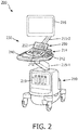
- FIG. 2 shows an illustration of an ultrasound imaging system which may include a control panel in accordance with principles of the present invention.
- the ultrasound imaging system 200 may include one or more of the components of the ultrasound imaging system 10 previously described.
- the ultrasound imaging system 200 may include beamformer, signal processor, B-mode processor, scan converter, multiplanar reformatter, volume renderer, image processor, graphics processor, and/or other processors which may control various operations of the ultrasound imaging system.
- One or more of these components may be provided in an ultrasound imaging base 210.
- the ultrasound imaging base is implemented in the form of a mobile base or cart 219 (e.g., as shown in FIG. 2 ).
- one or more of the components of the ultrasound imaging system may be implemented in hardware and software and provided in a portable form (e.g., a tablet computer).
- the ultrasound imaging base may be implemented in the form of a portable computer (not shown).
- the ultrasound imaging base may be configured to be coupled to an ultrasound probe (e.g., probe 12 of FIG. 1 ) and to control transmission of ultrasound and reception of ultrasound echoes with the probe.
- the ultrasound imaging system 200 may include a one or more components which provide a user interface 230 for controlling the operation of the system.
- the user interface 230 may include a display 216, e.g., for displaying image data.
- the display 216 is attached to the cart 219 via an articulating arm 215-2 which enables re-positioning of the display 216 such as to allow a displayed image to be viewable by others (e.g., the patient, another ultrasound operator, or a clinician).
- the user interface 230 may include one or more user controls, which may be provided on a control panel 214, which may also be coupled to the base 219 via an articulating arm 215-1.
- the user controls may include hard controls (e.g., mechanical controls) and soft controls (e.g., graphical user interface elements).
- hard controls it is generally implied that a position and/or control functions of a particular control may be fixed (e.g., hard-wired), while typically soft controls refer to user controls which may be re-configurable (e.g., to change a location of the control and/or functionality of the control).
- One or more of the controls 242 may be arranged on a field panel 240.
- the field panel may be generally horizontal (plus or minus 25 degrees) which may correspond to a preferred ergonomic position.
- One or more of the controls 242 may provide a tactile interface whereby a user may locate certain controls by touch.
- one or more soft controls may be provided in a display area 252 of a touch-sensitive display 250.
- Flat control panels such as those provided by touch-sensitive displays have the advantage of configurability (e.g., different user controls may be provided in different user interface screens for virtually any number of different applications).
- one drawback of existing flat control panels is the inability for a user to locate controls by touch.
- a user may need to turn their attention to the touch screen and away from the patient or image to locate the control.
- invocation of functions associated with soft controls on existing touch control panels may be instantaneous regardless of the force applied to the soft control.
- the user may need to "hover" their finger over the soft control until ready to invoke the function. That is, after a user visually locates a control their finger must remain poised above the control until they are ready to select the control.
- Conventional ultrasound imaging systems often include tactile controls (e.g., mechanical controls such as push buttons, knobs, switches and the like, which allow an operator to locate controls by touch without having to divert their attention from the image or patient.
- tactile controls e.g., mechanical controls such as push buttons, knobs, switches and the like, which allow an operator to locate controls by touch without having to divert their attention from the image or patient.
- mechanical controls may provide such a tactile interface
- the use of mechanical controls may have drawbacks particularly in medical application where cleaning and sterilization of medical equipment including the control panels of ultrasound systems is necessary.
- To minimize bioburden build-up a control panel of a medical imaging system may need to withstand high levels of liquid disinfectants.
- mechanical controls introduce openings or gaps in a control surface, which may increase the risk of damage to the control panel, e.g., due to liquid intrusion into the panel.
- an improved control panel for a medical imaging system such as ultrasound system
- a medical imaging system such as ultrasound system
- control panels in accordance with the present disclosure may be provided for any other type of medical imaging system, or more broadly other medical equipment that includes a control panel.
- the examples herein may also be used in other applications such as in industrial applications (e.g., control panels of manufacturing machines or vehicles where contamination from oil, chemicals, or debris may be a concern) or consumer applications (e.g., control panels of consumer products such as TV, video games, home appliances, etc.) and other applications.
- FIG. 3 is a perspective drawing a control panel in accordance with the present invention.
- the control panel 300 may be used to implement the control panel 214 of FIG. 2 .
- the control panel 300 may include one or more control surfaces (e.g., an upper surface or panel 302, a lower surface or panel 304, or both as shown in the example in FIG. 2 ).
- the control panel 300 may include only a single control surface or panel.
- the control panel 300 may include a touch sensitive display panel for the lower panel 302.
- the control panel 300 may include a plurality of user control areas (e.g., control areas 306) provided at fixed locations along a control surface of the control panel 300.
- the control areas may correspond to user controls of the control panel 300.
- a sealing layer e.g., sealing layer 316
- the sealing layer 314 may include at least one topographical feature (e.g., topographical feature 316) which may be associated with at least one of the user control area.
- a pressure-sensitive capacitive touch layer (not shown in the view FIG. 3 ) may be provided below the sealing layer 306 at least one of the user control areas.
- the capacitive touch layer may be a single continuous encompassing a plurality and in some cases all of the user control areas of the control panel. In other examples, a plurality of separate or discrete capacitive touch sensors may form the capacitive touch layer.
- the pressure-sensitive capacitive touch layer may be configured to activate a user control responsive to a touch, which is associated with an amount of pressure exceeding a threshold amount. For example, the pressure-sensitive capacitive touch layer may be configured to detect a touch which is associated with an amount of pressure applied to a given user control area and to invoke a function of the user control area responsive to the touch only if the amount of pressure exceeds a threshold amount.
- the sealing layer may be opaque and may be colored or patterned (e.g., via an in-mold labeling process) with graphics such as to indicate the type of control or provide information about the control or its operation.
- the sealing layer may be partially transparent such as to allow illumination of graphics that may be patterned on the sealing layer.
- the sealing layer may be translucent, so as to allow diffused illumination from below such as to indicate active controls. Illumination may be provided via a light source such as an LED or other type of backlighting located below the sealing layer.
- the sealing layer may be substantially optically transparent, such as when used in combination with a touch sensitive display, to allow displayed graphics to be visible though the sealing layer, an example of which is described further below.
- the upper panel 302 may include a display 308.
- the display 308 may be implemented using liquid crystal display (LCD) technology, light-emitting diode (LED) display technology, organic light-emitting diode (OLED) display technology or another type of display technology.
- the display 308 may be configured to detect a touch such as made by a finger or stylus at one or more locations on the display 308, and may also be referred to as touch-sensitive display or touch screen.
- the display 308 may be configured to provide one or more soft controls, for example by displaying a graphical representation of a user control such as a button (e.g., a GUI control element) over a designated area on the touch-sensitive display 308.
- a button e.g., a GUI control element
- the soft controls may include variable-location soft controls 310 and fixed-location soft controls 312.
- Variable-location soft controls 310 may be provided at different locations on the display 306, such as when displaying different user interface screens which may have different layouts of the various user interface elements.
- a fixed-location soft control 312 may be displayed in a fixed location, such as in a row along the bottom of the display 306. While the functionality of both the variable-location and fixed-location soft controls may vary depending on the particular user interface screen being displayed, the fixed-location soft controls associated with a particular user interface screen may always be provided in a specific location and arrangement on the display 306.
- the lower panel 304 may include any number of user controls (e.g., faux rotary encoders, pushbuttons, or sliders 322-326, respectively, a trackpad 330, and control buttons 332, or others) which may resemble mechanical operator controls of different types.
- the user controls may be made to resemble real mechanical controls such as to provide a tactile interface.
- the user controls may be made to resemble real mechanical controls via a combination of topographical features 334 and/or shaping of the sealing layer and any support layers that may be incorporated in a given configuration of a control panel in accordance with examples herein.
- Faux rotary encoders 322 may be designed to resemble and mimic the function of a real (e.g., electro-mechanical) rotary encoder.
- a faux rotary encoder may be configured to receive user input in the form of a finger swipe to mimic the rotary movement of a real encoder, rather than requiring an actual rotary input.
- a faux rotary encoder may be provided below a continuous sealing layer facilitating a sealed control panel that does not include openings as may otherwise be required to accommodate a rotary shaft.
- a faux rotary encoder may be implemented using a touch-sensor (e.g., a capacitive sensor) which is operable to detect a finger swipe.
- topography may be imparted to provide a tactile feel of the faux rotary encoder 322 such as to enable locating of the control by touch.
- Tactile and/or audible feedback may be utilized to provide user feedback along with that given on an imaging display or touch panel display.
- Faux sliders 326 may be designed to resemble and mimic the function of any of a variety of slider controls, such as a TGC (Time Gain Compensation) slider used on some ultrasound machines. As shown in FIG. 3 , multiple knob-like protrusions can be included in the control panel in order to look like TGC slider knobs.
- a faux slider 326 may be configured to sense the application of a touch, or touch with pressure along a side of the control to mimic the sliding motion of a real (e.g., electro-mechanical) slider without necessitating actual movement of the faux slider.
- knobs with fingers could be sensed by the knob via projected capacitance or a force sensor and be distinguished as an increase or a decrease of time gain compensation (TGC).
- TGC time gain compensation
- a tap on the top, or a touch on both sides could "center" the gain.
- Tactile and/or audible feedback may be utilized to provide user feedback along with that given on an imaging display or touch panel display.
- a faux slider may be implemented below a continuous sealing layer to enable a sealed control panel that does not include openings such as may otherwise be required to accommodate the input shaft of a real slider.
- Faux pushbuttons 324 and control buttons 332 may function similar to mechanical pushbuttons, where downward pressure would activate or toggle the corresponding function, but without necessitating actual downward displacement of the upper surface of the user control.
- Trackpad 330 may function similar to a traditional trackpad, with taps representing "clicks" or activating actions and finger swipes representing movement of a cursor or item. Trackpad 330 may provide the functionality of a trackball without the need for the rotating component of a conventional trackball.
- Secondary topographical features or surface features may be provided on or near some of the user controls, for example in the form of raised bars or surfaces 350a, bumps 350b, which may outline or provide a locator for a specific control, or any other type of topographical features including but not limited to depressions, holes, raised bars, plateaus, bumps, ridges, and surface textures, or combinations thereof, may be used for example to aid in locating a specific control by touch.
- One advantage of using faux controls such as the faux encoders 322 and faux sliders 326, examples of which will be described further with reference to FIGS. 7 and 8 , may be to enable a top surface of the control panel 300 to be provided as a single continuous layer (e.g., a sheet of material) which may seal the underlying components of the control panel 300 from the external environment. This may prevent or reduce the risk of ingress of contaminants and bioburden and may thereby protect sensitive electronics for example from liquid disinfectants and other materials.
- Fig. 4 is an exploded, perspective view of an embodiment of a control panel 400, showing exemplary layers of a control panel in accordance with the present disclosure.
- the control panel 400 may be used to implement the lower panel 204 of Fig. 3 .
- the top-most, outer layer of the control panel 400 is a sealing layer 420 which may be implemented as a single, seamless piece of material.
- the sealing layer 420 may be constructed from a pressure-formed (e.g., vacuum-formed) film.
- the sealing layer 420 may be shaped, for example using a pressure-forming process, from a generally flat sheet of material to a shaped layer which includes any number of topographical features 434.
- the sealing layer 420 may be provided with additional features (e.g., labels, coloring, etc.) for example using any of a number of known processes, including but not limited to an in-mold-decoration (IMD) process, an in-mold-label (IML) process.
- the material used for the sealing layer 420 may be a plastic film, such as polyester, of polyethylene terephthalate (PET) or another type of plastic material, which may be silk-screened to included decorations, labels, colors, and the like.
- the sealing layer 420 may be designed such that it has no holes.
- the sealing layer 420 may be shaped such that the end portions of the sealing layer are bent or shaped down to extend over an edge of the control panel. This may create a sealing lip against a back enclosure (not shown) to protect electronics and other layers of the control panel.
- the controls typical of a standard control panel which may include rotary encoders and slider controls with moving parts necessitating an opening in the layer, these controls may be replaced with the faux encoders 322 and faux sliders 326 described with reference to FIG. 3 .
- the capacitive touch layer 410 is sensitive to and detects the capacitance present in a finger or another object (e.g., a stylus) brought near or in contact with the capacitance touch layer 210.
- the sensitivity of the capacitive touch layer 410 may be tuned for example by tuning control parameters of a controller, such as an AMTEL touchscreen controller.
- the capacitive touch layer 410 is a projected capacitance, or P-Cap, layer. In other examples, other types of capacitive touch technology may be used.
- the capacitive touch layer 410 is configured to be pressure-sensitive.
- the capacitive touch layer 410 may be coupled to a controller to be able to detect an amount of pressure or force associated with touch, thereby allowing different functions to be enabled based on the amount of pressure of the detected touch.
- the capacitive touch layer 410 may be coupled to a controller, which may be positioned elsewhere within an enclosure of the system, e.g., a flexible circuit (not shown).
- the capacitive touch layer 410 may be configured to perform a function (e.g., invoke the functionality of a user control associated with a particular user control area to which pressure is applied) only if the pressure exceeds a threshold.
- the capacitive touch layer 410 may enable an operator to tactilely locate and to rest a finger on a control lightly without activating the control, and only activate the control when additional pressure exceeding the threshold is detected by the capacitive touch layer 410.
- the pressure threshold may be tuned as appropriate for a particular application and/or taking into consideration the specific panel configuration (e.g., number of layers, thickness of layers, type of user control, etc.)
- one or more support layers may be provided between the sealing layer 420 and the capacitive touch layer 410 (e.g., support layer 415 as shown in FIG. 4 ), below the capacitive touch layer, or both.
- the support layer 415 may provide a support structure for the relatively thin sealing layer.
- the support layer 415 may follow a contour of the shaped sealing layer such as to fill in cavities defined between by the contour of the sealing layer 420.
- the support layer 415 may be created by backfilling the "shell" of the sealing layer 420 with an injection molding process.
- FIG. 5A shows a cross-sectional view of layers of a control panel in accordance with one embodiment.
- a sealing layer 520a is provided as the upper-most or top layer and encloses underlying layers and/or electronics of the control panel.
- the sealing layer 520a may extend continuously over a plurality of user control areas of the control panel.
- the sealing layer 520a may thus provide an environmental seal.
- the sealing layer 520a may include topographical features 522a and 524a, which may aid an operator in locating a user control area by touch.
- the sealing layer 520a may have a lip around its outer edge that extends down and over the outer edges of the other layers and to provide a seal against contaminants.
- topographical features may be shaped such that the particular location along the sealing layer resembles a mechanical control.
- the sealing layer 520a may be shaped (e.g., via pressure forming) to include a topographical feature in the form of a protrusion that resembles a mechanical control, such as a push button or other type of control.
- Some of the topographical features e.g., feature 524a
- the secondary topographical feature may provide additional locator functionality to enable to the user to locate a specific one of a plurality of similarly shaped controls.
- a support layer 515a which is shaped to mirror a contour of the sealing layer 520a.
- an upper surface 528a of the support layer may have the same shape as the lower surface 526a of the sealing layer 520a.
- the sealing layer may be a shaped film pressure formed to follow a predetermined contour and the support layer may be a molded plastic layer that fills the cavities defined by the shape of the sealing layer 520a.
- the sealing layer 520a may be relatively thin (e.g., up to 1mm, up to 5mm, or greater) thus the support layer 515a may provide structural support for the topographical features 522a, 524a formed in the sealing layer 520a and/or for the sealing layer 520a itself.
- the secondary topographical features 524a may be substantially smaller than other topographical features and may not have a corresponding contoured lower surface but may be formed as projections from or indentations on the upper surface of the sealing layer 520a.
- the bottom surface 530a of the support layer 515a may be generally flat and correspond to the planar surface of the capacitive touch layer 510a.
- the capacitive touch layer 510a is a generally planar layer that provides a touch sensing function for the control panel.
- the capacitive touch layer 510a may be a p-cap layer and in preferred examples a pressure-sensitive p-cap layer.
- a finger or stylus would come in contact with the upper surface of the sealing layer 520a. Varying amounts of pressure associated with a touch by a finger or stylus on the sealing layer 520a may be detected by the capacitive touch layer 510a through the support layer 515a.
- the capacitive touch layer 510a may be a pressure-sensitive P-Cap layer which is configured to cause functionality of a user control to be invoked only if the pressure exceeds a predetermined amount.
- the amount of pressure may be determined based on the size of the touch "footprint" detected on the sealing layer 520a. For example, a light touch on the sealing layer 520a may detected as a small circle representing only the small point of contact by the finger makes with the sealing layer 520a, and a heavier touch (more downward pressure) may be detected as a circle of a larger diameter (e.g., as the tip of the finger spreads out on the sealing layer 520a from the increased pressure.
- FIG. 3B shows another embodiment for the layered structure of a control panel in accordance with the examples herein.
- the layers again include an upper-most or top sealing layer 520b, a support layer 515b, and a capacitive touch layer 510b.
- the support layer 515b is provided below the capacitive touch layer 510b such that the capacitive touch layer 510b is sandwiched between the sealing layer 520b and the support layer 515b.
- the capacitive touch layer 510b is a shaped layer, the contour of may follow the contour of the sealing layer 520b.
- the capacitive touch layer 510b may be flexible (e.g., implemented using flexible circuitry) and may be configured to fit in the cavities defined by the sealing layer 520b by the support layer 515b.
- the lower surface 526b of the sealing layer 520b may correspond in shape to the upper surface 532b of the capacitive touch layer 510b.
- the support layer 515b has a contoured upper surface 528b which corresponds in shape to the lower surface 534b of the capacitive touch layer 510b to thereby provide support for the two shaped layers above.
- the layers structure may include one or more topographical features 522b and 524b which may be similar to those in the previous example.
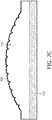
- FIG. 3C shows another embodiment of a layer structure for a control panel in accordance with the examples herein.
- the capacitive touch layer 510c is a planar layer and the sealing layer 520c is provided directly over the capacitive touch layer 510c.
- the lower surface 526c of the sealing layer 520c corresponds to the upper planar surface 532c of the capacitive touch layer 510c.
- the layered structure may be formed by molding the sealing layer 520c and support layer 515c together, such as through an injection molding or overmolding process.
- the two layers may be formed as one piece 220a.
- the sealing layer 520c and capacitive touch layer 510c may be formed separately and then bonded together.
- FIGS. 6A and 6B show further embodiments of layer structures for control panels in accordance with the present disclosure.
- the layered structure similarly includes a capacitive touch layer 610a and a sealing layer 620a with the support layer being discontinuous.
- the support layer is formed of a plurality of separate support pieces 615a-1-615a-3, which may abut one another in the assembled control panel, or may be slightly spaced apart. In the illustrated example, only three separate support pieces are shown, however, any appropriate number of support layer pieces may be used in other examples.
- Separating the support layer into components may improve touch detection such as by isolating one user control from another.
- a touch e.g., by a finger
- a discontinuous support layer may be formed, for example by an insert molding process in which inserts are provided at the locations of separation during the molding of the support layer.
- the support pieces may be formed as separate components that are then assembled (e.g., bonded) to the other layers.
- the support layer is again a discontinuous layer, but in this example, the support layer is provided only within the cavities defined by the lower surface of the sealing layer 620b.
- a portion of the lower surface of the sealing layer 620b is provided in contact with the capacitive touch layer 610b and support pieces (e.g., 615b-1 and 615b-2) fill only the space between the sealing layer 620b and capacitive touch layer 610b, such as may be formed due to the inclusion of topographical features in the sealing layer 620b.
- an additional support layer (not shown) may be provided below the illustrated layered structure, to provide additional support to the sealing layer 620b and capacitive touch layer 610b.
- FIGS. 7A-7B are perspective drawings of an example user control in accordance with further examples.
- the user control in FIGS. 7A and 7B may be used to implement a faux rotary encoder, such as the faux rotary encoder 322 of control panel 300.
- FIG. 7A shows a view of the faux encoder 700
- FIG. 7B shows an exploded cross-sectional view of the faux encoder 700.
- the faux encoder 700 includes a sealing layer 720, a capacitive touch layer 710 (e.g., a pressure sensitive p-cap layer), and a support layer 715.
- the support layer 715 may be rounded to impart a topography that resembles a rotary control.
- the capacitive touch layer 710 may be a shaped layer provided below the shaped sealing layer 720.
- the capacitive touch layer 710 may be a flexible layer.
- the sealing layer 720 may include additional topographical features 760 (e.g., transverse indentations or notches, ridges or ribs, or other surface features), which may mimic the tactile feel of a real (e.g., electro-mechanical) rotary control. It will be understood that these additional topographical features are not required for proper function of the faux encoder 700 and may be omitted.
- the views in FIGS. 7A and 7B are partial simplified views, in which the sealing layer 720 is shown extending over only the top surface of the other layers for illustration, however it will be understood that the sealing layer 720 may extend over the sides and completely enclose the other layers.
- a user may move or sweep their fingertip along the curved surface of the sealing layer 720, simulating the rotation of a traditional rotary encoder.
- the movement of the fingertip may be detected by the capacitive touch layer 710 as a moving "footprint" of a touch along the surface of the sealing layer 720. This moving touch can then be interpreted as a degree of rotation or a distance of movement which can be passed along to a processor of the medical diagnostic machine as a user input.
- the order of the support layer 715 and capacitive touch layer 710 may be, such that the application of a pressure on the sealing layer 720, such as by a touch by a finger, may be detected by the capacitive touch layer 710 through the support layer 715.
- Additional functionality of a conventional rotary encoder, such as that of a push button may be provided in the faux encoder 700 for example by an adjacent faux push button (not shown) or by performance of the additional function responsive to a detection of a movement different than swipe (e.g., a lift and tap, a double-tap, or other) on the faux encoder surface.
- swipe e.g., a lift and tap, a double-tap, or other
- a variety of other user controls may be implemented in similar manner as that of the faux encoder 700 shown in Figs. 7A and 7B .
- FIG. 7C shows another example of a portion of a control panel comprising a user control implemented as a faux rotary encoder.
- the control panel includes a capacitive touch layer 710', a sealing layer 720', and a support layer 715'.
- the capacitive touch layer 710' may be a implemented using a projected capacitance sensor which is configured to be pressure-sensitive such that the capacitive touch layer 710' is operable to invoke a response (e.g., execute a command associated with the user control) when a pressure on the control panel at the location of the user control exceeds a predetermined amount.
- This threshold amount may be selected to correspond to a lower amount of pressure that may result from the user tactilely locating, and placing or lightly resting their finger on the control.
- the control panel may ignore a touch at the lower pressure and only invoke the corresponding function when the pressure exceeds the threshold, e.g., responsive to the user pressing on or otherwise operating the user control to select the corresponding function.
- the capacitive touch layer 710' (e.g., p-cap layer) is a flat or generally planer layer positioned below the contoured sealing layer 720'.
- the sealing layer 720' may be formed from a thin film of plastic which is pressure formed into the desired shape, in this case to resemble a ribbed rounded projection similar to a rotary control.
- a support layer 715' having a contoured upper surface with a shape corresponding to the contour of the sealing layer is provided below the sealing layer 720' to support the otherwise flexible sealing layer in its pressure formed shape.
- the rounded shape of the faux rotary encoder may function as a topographical feature to assist the user in tactilely locating the user control.
- the ribbed control surface of the control panel may function as secondary topographical features, which may simulate to a user the tactile feel of operating a real rotary control rather than a faux rotary control.
- FIG. 8 is a cross-sectional view of an embodiment of a user control the form of a faux slider control which may be implemented in a control panel of the present disclosure.
- the faux slider control 800 may be used to implement one or more of the faux slider controls 326 of the control panel 300.
- a faux slider 800 may be constructed as a layered structure which includes as a cylindrical or post-shaped support layer 815.
- a capacitive touch layer 810 may be placed around an exterior of the support layer 815 such as along one or more sides (e.g., opposite sides) of the cylindrical support layer 815. The location of the capacitive touch layer 810 may be selected based on the expected location and/or direction of the touch.
- capacitive touch layer 810 may be located on the opposite sides that represent the two different directions in which the slider-style control might be moved.
- a sealing layer 820 is provided around the capacitive touch layer 810 and support layer 815 to fully enclose the underlayers of the faux slider control 800.
- the faux slider 800 may work by detecting pressure on opposite sides of the cylindrical shape. For instance, detecting pressure on the left side of the control shown in FIG. 8 may indicate a desire to "move” the faux slider toward the right, and detecting pressure on the right side of the control may indicate a desire to "move” the faux slider toward the left.
- the faux slider 800 may not actually slide or move, but is instead configured to interpret pressure applied to a side of the control as a user input corresponding to a desired movement of the control in a particular direction.
- the capacitive touch layer 810 may instead be provided as a flat or generally planer layer located below the support layer 815.
- the support layer and sealing layer may be configured to allow the user's finger or other portion of the user's hand (e.g., palm or side of the user's palm or finger) conductively couple to the capacitive touch layer.
- a force-sensitive resistive device or a piezo-electric strain cell device may be used to allow for detecting where force is being applied to the faux control 800.
- piezo-electric strain cells may be attached at one or more locations around the perimeter of the support layer 815 to detect strains on the support layer structure associated with applied force and the detected strains may be used to determine on which side of the structure force is being applied to and thereby the direction in which the user is operating the control.
- a faux slider in accordance with the present disclosure may be implemented differently, as described further below with reference to FIG. 10 .
- control panel may include a touchscreen in addition to or instead of the field control panel (e.g., control panel 304).
- the user interface may include only touch screen controls on a single or multiple panels.
- touch-sensitive displays on medical diagnostic systems may have some shortcomings, such as the inability to locate specific controls by touch and/or the inability to rest a finger on the control once located before activating the control.
- the examples herein may address some of the shortcomings of existing touch-sensitive display panels.
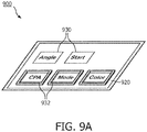
- FIGS. 9A-9C show perspective, exploded and cross-sectional illustrations of a touch-sensitive, flat panel display for use in a control panel in accordance with the present disclosure.
- the touch-sensitive flat panel display 900 may be used to implement the display 302 of control panel 300.
- the display 900 may be configured to display a GUI which includes one or more soft controls.
- the display may be configured to provide variable-location soft controls 930 and fixed-location soft controls 932.
- the display may include a substantially optically transparent sealing layer 920, which may include built-in topographical features to aid an operator in locating controls by touch.
- the optically transparent sealing layer 920 may include one or more topographical features 934 which may be provided at user control locations of the display that are associated with fixed-location soft controls 932.
- the display 900 may have a layered structure which includes a capacitive touch layer 910 and a sealing layer 920 provided as the outer-most or top layer of the display.
- An optically transparent cover layer 970 e.g., glass or polycarbonate
- the cover layer 970 may be a generally rigid layer that protects the underlying components of the display 900 as well as provides part of the rigid enclosure of the display 900.
- the capacitive touch layer 910 may be a pressure-sensitive layer which is configured to perform different functions or selectively perform a function responsive to different detected pressure on the display.
- the sealing layer 920 may include one or more features of other sealing layers described herein.
- the sealing layer 920 may be a relatively thin layer (e.g., a pressure-formed film of plastic) shaped to include topographical features (e.g., features 934 in FIG. 9B ) to facilitate the locating of a user control by touch.
- the sealing layer 920 in this example is optically transparent.
- the sealing layer 920 may be bonded to the cover layer 970. In this example no additional support structure is provided beyond the generally planar cover layer 970 thus when the layers are assembled, air filled gaps 972 may remain between the sealing layer 920 and the cover layer 970.
- An optically transparent cover layer similar to layer 970 may be optionally provided in any of the examples previously described, for example in the layered structures in FIGS. 5A and 5C , which cover layer may similarly be provided over the capacitive touch layer so as to protect the underlying capacitive touch layer.
- the display 900 may be configured using known techniques to provide soft controls in any desired combination.
- the display may be specifically configured to provide certain controls in a fixed location (e.g., fixed-location controls 932) on the display so as to align with the location of the topographical features of the sealing layer 920. While the particular functionality of a fixed-location control 932 may change from one user interface screen to another, the location of the fixed-location control 932 may remain substantially the same, such that the user may be able to locate the fixed-location control by touch.
- the topographical features 932 may be implemented as raised portions of the sealing layer 920 which may correspond to an outline of a fixed-location soft control 932, in this example raised rectangular outlines. The topographical feature need not encircle the soft control. In other examples, different arrangements may be used, for example one or more bumps, ridges or ribs, or other types of features may be provided in the sealing layer at a location corresponding a fixed-location control 932.
- variable-location buttons 930 may be used to enter into a specific operating mode while looking at the display 900. Once entered into the proper mode, the operator may then return their focus to the patient to adjust the ultrasound probe or to the ultrasound image being displayed such as on a main display area. Then, a particular function associated with a fixed-location soft control may be performed without the operator having to look back at the flat panel display 900, as the operator may be able to located the desired control by touch such as by tactilely locating the topographical feature provided over the user control location of the desired control.
- the pressure sensitive capability of the capacitive touch layer 910 of display 900 allows the user to rest a finger on the operator control located by touch without activating it until activation is desired at which time the operator may apply additional pressure to the display to activate the corresponding function.
- the transparent sealing layer 920 may extend over the entire surface of the touch screen and may be bonded to the cover layer 970 (e.g., glass or polycarbonate) of the touch screen. In other examples, the transparent sealing layer may wrap around an edge of the touch screen, and in some examples may be attached (e.g., bonded, fused, laser welded, or otherwise fastened) to a perimeter portion of a housing of the touch screen.
- user feedback to indicate the selection of a control may be provided by audible feedback such as a click sound or mechanical tactile feedback such as vibration.
- mechanical tactile feedback may be implemented using an overall bump from a solenoid armature tapping on the back of the support layer or another part of the structure of the panel (e.g., a cover layer), a piezo-electric transducer attached to the back of the support layer or another structure, a voice-coil speaker mounted on the back of the support layer or another structure, an eccentric rotating mass vibration motor mounted on the back of the support layer or another structure, a "Force Reactor" vibration device supplied by ALPS, or any combinations thereof.
- the control panels herein may be configured to reduce the damping of such mechanical feedback by the support layer for example, by providing a discontinuous support layer as described herein.
- FIG. 10 shows a simplified cross-sectional view of user controls for a control panel in accordance with further examples of the present disclosure.
- the example in FIG. 10 illustrates a plurality of faux sliders 1004 and a faux button-type control 1002.
- the control 1002 is constructed using a pressure-sensitive capacitive layer 1010 provided below a contoured sealing layer 1020.
- the capacitive layer 1010 is a flexible layer (e.g., flex circuit including conductive traces operatively arranged to provide a capacitive touch sensor) and an additional support layer (e.g., backer plate 1050) may be provided below the capacitive layer 1010.
- an additional support layer e.g., backer plate 1050
- the sealing layer 1020 may be formed of a thin film of plastic, which can be transparent, partially transparent, translucent, or opaque, as may be appropriate for a particular application.
- the thin film which in some examples may be 1mm thick or less, may be shaped to include one or more topographical features, for example topographical feature 1022.
- a support layer 1015 fills the space between the sealing layer 1020 and the capacitive layer 1010.
- the support layer 1015 is relatively rigid as compared to the sealing layer 1020 and thus provides structural support for the otherwise flexible sealing layer.
- the sealing layer 1020 and support layer 1015 are formed of materials which do not significantly inhibit capacitive coupling between the capacitive layer 1010 and the user's finger or other portion of their hand.
- the sealing layer 1020 includes at least one topographical feature to aid the user in tactilely locating the one or more user controls.
- the topographical feature 1022 may define the shape of the button type control 1002.
- the sealing layer 1020 and support layer 1015 may be bonded, in some examples bonded during the forming process, with the upper surface of the support layer 1015 following the contour of the sealing layer 1020.
- the sealing layer 1020 may cover most or substantially the entire upper surface of a control panel.
- Faux sliders 1004 may be constructed using a pressure-sensitive capacitive layer 1010 provided below a contoured sealing layer 1020.
- the pressure-sensitive capacitive layer 1010 may be operatively associated with a support layer or structure 1040, which may be shaped to resemble the structure of a real (electro-mechanical) slider control.
- the support structure 1040 includes a base 1042 and a post 1044 extending generally perpendicularly from the base 1042.
- the support structure 1040 may be formed of a generally rigid material, such as metal or plastic, which does not substantially inhibit capacitive coupling.
- the support structure 1040 is coupled to the underlying layers via a layered structure 1016 configured to permit selectively conductively coupling the support structure 1040 to the capacitive layer 1010.
- the layered structure 1016 includes an electrically conductive pad 1018, which may be constructed from a conductive foam pad, and an insulating pad 1017, which may be constructed from a dielectric material such as rubber.
- the upper surface of the conductive pad 1018 is fixed to the bottom surface of the base 1042 and the bottom surface of the insulating pad 1017 is placed over the capacitive layer 1010 to mechanically couple the support structure 1040 to the capacitive layer 1010.
- the insulating pad 1017 may have a smaller footprint than the conductive pad 1018 such that the support structure 1040 is balanced over the capacitive layer 1010 and is able to see saw when force is applied to the support structure 1040, e.g., via the post 1044.
- the insulating pad 1017 may be narrower than the conductive pad 1018 such that a gap is defined between the bottom surface of the conductive pad 1018 and the upper surface of the capacitive layer 1010. The gap prevents conductive coupling between the structure 1040 and the capacitive layer 1010 until a sufficient force is applied to the structure 1040.
- the conductive pad 1018 includes a recess and the insulating pad 1017 is received in the recess but extends beyond the depth of the recess. In this example, a portion of the conductive pad 1018 extends over the insulating pad 1017 between the insulating pad 1017 and the base 1042 thereby providing a larger conductive contact area between the pad 1018 and base 1042.
- the insulating pad 1017 may be provided in a through slot in the conductive pad 1018 and may contact the base 1042 of support structure 1040.
- one side of the base 1042 conductively couples to the capacitive layer 1010 via the conductive pad 1018.
- the opposite side of the base 1042 conductively couples to the capacitive layer 1010 via the conductive pad 1018.
- the structure 1040 returns to its nominal or non-deflected position e.g., with the post 1044 extending generally perpendicularly relative to the capacitive layer 1010.
- the structure 1040 is substantially fully enclosed below a sealing layer.
- the structure 1040 is enclosed by a sealing cap 1032 provided over a portion of the post 1044 and a shoulder 1030 substantially enclosing the base 1042 and layered structure 1016.
- the sealing cap 1032 is made from a material which permits conductive coupling between the user's hand and the capacitive layer 1010.
- the shoulder 1030 may made from a material which permits conductive coupling between the user's hand and the capacitive layer 1010.
- an insulating gasket 1019 may be provided around the post 1044 to electrically insulate the post 1044 from a conductive shoulder 1030.
- cap 1032 and shoulder 1030 are illustrated as separate sealing components, in some examples, the cap 1032 and shoulder 1030 may be implemented using an integral or continuous layer, which may also be integral or continuous with the sealing layer 1020. In some examples, the shoulder, the cap, and the sealing layer, or any combination thereof may be made from the same material.
- a programmable device such as a computer-based system or programmable logic
- the above-described systems and methods can be implemented using any of various known or later developed programming languages, such as "C”, “C++”, “FORTRAN”, “Pascal”, “VHDL” and the like.
- various storage media such as magnetic computer disks, optical disks, electronic memories and the like, can be prepared that can contain information that can direct a device, such as a computer, to implement the above-described systems and/or methods.
- the storage media can provide the information and programs to the device, thus enabling the device to perform functions of the systems and/or methods described herein.
- the computer could receive the information, appropriately configure itself and perform the functions of the various systems and methods outlined in the diagrams and flowcharts above to implement the various functions. That is, the computer could receive various portions of information from the disk relating to different elements of the above-described systems and/or methods, implement the individual systems and/or methods and coordinate the functions of the individual systems and/or methods described above.
- the present system may have been described with particular reference to an ultrasound imaging system, it is also envisioned that the present system can be extended to other medical imaging systems where one or more images are obtained in a systematic manner. Accordingly, the present system may be used to obtain and/or record image information related to, but not limited to renal, testicular, breast, ovarian, uterine, thyroid, hepatic, lung, musculoskeletal, splenic, cardiac, arterial and vascular systems, as well as other imaging applications related to ultrasound-guided interventions. Further, the present system may also include one or more programs which may be used with conventional imaging systems so that they may provide features and advantages of the present system.
Landscapes
- Engineering & Computer Science (AREA)
- Health & Medical Sciences (AREA)
- Life Sciences & Earth Sciences (AREA)
- Physics & Mathematics (AREA)
- Theoretical Computer Science (AREA)
- General Engineering & Computer Science (AREA)
- Medical Informatics (AREA)
- Public Health (AREA)
- Biomedical Technology (AREA)
- Heart & Thoracic Surgery (AREA)
- Pathology (AREA)
- Molecular Biology (AREA)
- Surgery (AREA)
- Animal Behavior & Ethology (AREA)
- General Health & Medical Sciences (AREA)
- Radiology & Medical Imaging (AREA)
- Veterinary Medicine (AREA)
- Nuclear Medicine, Radiotherapy & Molecular Imaging (AREA)
- Biophysics (AREA)
- Human Computer Interaction (AREA)
- General Physics & Mathematics (AREA)
- Ultra Sonic Daignosis Equipment (AREA)
- Position Input By Displaying (AREA)
Applications Claiming Priority (3)
| Application Number | Priority Date | Filing Date | Title |
|---|---|---|---|
| US201662356654P | 2016-06-30 | 2016-06-30 | |
| US201762490054P | 2017-04-26 | 2017-04-26 | |
| PCT/EP2017/066215 WO2018002272A1 (en) | 2016-06-30 | 2017-06-29 | Sealed control panel for medical equipment |
Publications (2)
| Publication Number | Publication Date |
|---|---|
| EP3478181A1 EP3478181A1 (en) | 2019-05-08 |
| EP3478181B1 true EP3478181B1 (en) | 2020-08-05 |
Family
ID=59350883
Family Applications (1)
| Application Number | Title | Priority Date | Filing Date |
|---|---|---|---|
| EP17739908.6A Active EP3478181B1 (en) | 2016-06-30 | 2017-06-29 | Sealed control panel for medical equipment |
Country Status (5)
| Country | Link |
|---|---|
| US (1) | US11317894B2 (ja) |
| EP (1) | EP3478181B1 (ja) |
| JP (3) | JP6739556B2 (ja) |
| CN (1) | CN109414244B (ja) |
| WO (1) | WO2018002272A1 (ja) |
Families Citing this family (4)
| Publication number | Priority date | Publication date | Assignee | Title |
|---|---|---|---|---|
| KR102635050B1 (ko) * | 2016-07-20 | 2024-02-08 | 삼성메디슨 주식회사 | 초음파 영상 장치 및 그 제어방법 |
| US10788964B1 (en) * | 2019-05-10 | 2020-09-29 | GE Precision Healthcare LLC | Method and system for presenting function data associated with a user input device at a main display in response to a presence signal provided via the user input device |
| JP7384107B2 (ja) * | 2020-04-20 | 2023-11-21 | コニカミノルタ株式会社 | 操作入力装置及び超音波診断装置 |
| FR3126297B1 (fr) * | 2021-08-27 | 2023-10-13 | Supersonic Imagine | Système d'imagerie médical comprenant un écran tactile pliable |
Family Cites Families (34)
| Publication number | Priority date | Publication date | Assignee | Title |
|---|---|---|---|---|
| US7663607B2 (en) | 2004-05-06 | 2010-02-16 | Apple Inc. | Multipoint touchscreen |
| US6135958A (en) | 1998-08-06 | 2000-10-24 | Acuson Corporation | Ultrasound imaging system with touch-pad pointing device |
| US6492979B1 (en) | 1999-09-07 | 2002-12-10 | Elo Touchsystems, Inc. | Dual sensor touchscreen utilizing projective-capacitive and force touch sensors |
| US6530885B1 (en) | 2000-03-17 | 2003-03-11 | Atl Ultrasound, Inc. | Spatially compounded three dimensional ultrasonic images |
| US6443896B1 (en) | 2000-08-17 | 2002-09-03 | Koninklijke Philips Electronics N.V. | Method for creating multiplanar ultrasonic images of a three dimensional object |
| CA2527970C (en) * | 2003-06-18 | 2014-07-29 | Ambric, Inc | Integrated circuit development system |
| JP2006020668A (ja) * | 2004-07-06 | 2006-01-26 | Shimadzu Corp | 投影形操作装置 |
| EP1817653A1 (en) * | 2004-10-12 | 2007-08-15 | Koninklijke Philips Electronics N.V. | Ultrasound touchscreen user interface and display |
| WO2007099733A1 (ja) * | 2006-03-01 | 2007-09-07 | Sharp Kabushiki Kaisha | タッチパネルを用いた入力装置 |
| JP2009119135A (ja) * | 2007-11-16 | 2009-06-04 | Ge Medical Systems Global Technology Co Llc | 超音波撮像装置および医用電子装置 |
| US8547339B2 (en) | 2008-01-04 | 2013-10-01 | Tactus Technology, Inc. | System and methods for raised touch screens |
| JP2009229685A (ja) * | 2008-03-21 | 2009-10-08 | Stanley Electric Co Ltd | 液晶表示装置及びその製造方法 |
| US20100191120A1 (en) * | 2009-01-28 | 2010-07-29 | General Electric Company | Apparatus and method for controlling an ultrasound system based on contact with an ultrasound probe |
| US9024907B2 (en) | 2009-04-03 | 2015-05-05 | Synaptics Incorporated | Input device with capacitive force sensor and method for constructing the same |
| US8253712B2 (en) * | 2009-05-01 | 2012-08-28 | Sony Ericsson Mobile Communications Ab | Methods of operating electronic devices including touch sensitive interfaces using force/deflection sensing and related devices and computer program products |
| FR2949007B1 (fr) | 2009-08-07 | 2012-06-08 | Nanotec Solution | Dispositif et procede d'interface de commande sensible a un mouvement d'un corps ou d'un objet et equipement de commande integrant ce dispositif. |
| JP2011072532A (ja) * | 2009-09-30 | 2011-04-14 | Konica Minolta Medical & Graphic Inc | 医用画像診断装置、および超音波診断装置 |
| CN201638197U (zh) * | 2010-03-30 | 2010-11-17 | 毛肖林 | 一种鼓气结构的触控面板 |
| EP2375314A1 (en) * | 2010-04-08 | 2011-10-12 | Research in Motion Limited | Touch-sensitive device and method of control |
| US8963886B2 (en) * | 2011-07-13 | 2015-02-24 | Flatfrog Laboratories Ab | Touch-sensing display panel |
| US9504448B2 (en) * | 2011-09-29 | 2016-11-29 | Koninklijke Philips N.V. | Ultrasonic diagnostic imaging system with contextually variable control panel |
| CN103135810B (zh) * | 2011-11-24 | 2016-09-07 | 比亚迪股份有限公司 | 一种触摸屏的压力灵敏度调节方法及系统 |
| US20140337883A1 (en) | 2011-12-13 | 2014-11-13 | Thomson Licensing | Method and apparatus for networking media content consumption status in a group of users |
| JP5852461B2 (ja) * | 2012-02-14 | 2016-02-03 | 日立アロカメディカル株式会社 | 超音波探触子及びそれを用いた超音波診断装置 |
| US20130285735A1 (en) * | 2012-04-30 | 2013-10-31 | Delphi Technologies, Inc. | Operator control assembly |
| JP6031312B2 (ja) | 2012-09-28 | 2016-11-24 | 株式会社日立製作所 | 携帯型超音波撮像装置 |
| US9414810B2 (en) | 2013-01-24 | 2016-08-16 | B-K Medical Aps | Ultrasound imaging system |
| US9348453B2 (en) * | 2013-02-04 | 2016-05-24 | Nokia Technologies Oy | Touch sensing arrangement with first and second shield electrodes |
| KR20230157519A (ko) * | 2013-08-30 | 2023-11-16 | 가부시키가이샤 한도오따이 에네루기 켄큐쇼 | 표시 장치 |
| US9971428B2 (en) | 2013-12-30 | 2018-05-15 | Immersion Corporation | Devices, systems, and methods for using corrugated tessellation to create surface features |
| EP3117352A1 (en) * | 2014-03-14 | 2017-01-18 | B-K Medical ApS | Graphical virtual controls of an ultrasound imaging system |
| CN203839775U (zh) * | 2014-05-15 | 2014-09-17 | 浙江广厦建设职业技术学院 | 一种弱电配电箱 |
| CN204423347U (zh) * | 2014-12-23 | 2015-06-24 | 九江妙士酷实业有限公司 | 一种电容式触摸屏导航仪 |
| CN204558025U (zh) * | 2015-03-23 | 2015-08-12 | 深圳市美睿辰电子科技有限公司 | 一种安全防眩的mp3播放器 |
-
2017
- 2017-06-29 US US16/310,914 patent/US11317894B2/en active Active
- 2017-06-29 JP JP2018568366A patent/JP6739556B2/ja active Active
- 2017-06-29 CN CN201780041049.3A patent/CN109414244B/zh active Active
- 2017-06-29 WO PCT/EP2017/066215 patent/WO2018002272A1/en unknown
- 2017-06-29 EP EP17739908.6A patent/EP3478181B1/en active Active
-
2020
- 2020-07-21 JP JP2020124162A patent/JP7181259B2/ja active Active
-
2022
- 2022-09-14 JP JP2022146084A patent/JP7252403B2/ja active Active
Non-Patent Citations (1)
| Title |
|---|
| None * |
Also Published As
| Publication number | Publication date |
|---|---|
| EP3478181A1 (en) | 2019-05-08 |
| JP7252403B2 (ja) | 2023-04-04 |
| CN109414244B (zh) | 2022-04-12 |
| US11317894B2 (en) | 2022-05-03 |
| CN109414244A (zh) | 2019-03-01 |
| JP2019525794A (ja) | 2019-09-12 |
| JP2020171781A (ja) | 2020-10-22 |
| JP6739556B2 (ja) | 2020-08-12 |
| JP2022177150A (ja) | 2022-11-30 |
| JP7181259B2 (ja) | 2022-11-30 |
| WO2018002272A1 (en) | 2018-01-04 |
| US20190380683A1 (en) | 2019-12-19 |
Similar Documents
| Publication | Publication Date | Title |
|---|---|---|
| JP7252403B2 (ja) | 医療用機器のための封止されたコントロールパネル | |
| US6924752B2 (en) | Three-dimensional contact-sensitive feature for electronic devices | |
| EP2196150B1 (en) | Hand-held ultrasound system | |
| US8754873B2 (en) | System and method for measuring individual force in multi-object sensing | |
| JP2008198205A (ja) | 傾斜型タッチ制御パネル | |
| US20150007025A1 (en) | Apparatus | |
| US20110037695A1 (en) | Ergonomic control unit for providing a pointing function | |
| JP5667002B2 (ja) | コンピュータの入力装置および携帯式コンピュータ | |
| US9455101B2 (en) | Optically transmissive key assemblies for display-capable keyboards, keypads, or other user input devices | |
| US9465476B1 (en) | Electronic device with seamless protective cover glass input | |
| US20230168635A1 (en) | Modular Sensing Assembly for an Electronic Device | |
| JP4128385B2 (ja) | ポインティングデバイス | |
| KR102589770B1 (ko) | 초음파 이미징 시스템 | |
| EP3242190B1 (en) | System, method and computer program for detecting an object approaching and touching a capacitive touch device | |
| US11635891B2 (en) | Grid plate | |
| WO2010020986A2 (en) | An ergonomic control unit for providing a pointing function | |
| CN110286720A (zh) | 电子设备及应用启动方法 | |
| CN110297583A (zh) | 电子设备及电子设备的控制方法 |
Legal Events
| Date | Code | Title | Description |
|---|---|---|---|
| STAA | Information on the status of an ep patent application or granted ep patent |
Free format text: STATUS: UNKNOWN |
|
| STAA | Information on the status of an ep patent application or granted ep patent |
Free format text: STATUS: THE INTERNATIONAL PUBLICATION HAS BEEN MADE |
|
| PUAI | Public reference made under article 153(3) epc to a published international application that has entered the european phase |
Free format text: ORIGINAL CODE: 0009012 |
|
| STAA | Information on the status of an ep patent application or granted ep patent |
Free format text: STATUS: REQUEST FOR EXAMINATION WAS MADE |
|
| 17P | Request for examination filed |
Effective date: 20190130 |
|
| AK | Designated contracting states |
Kind code of ref document: A1 Designated state(s): AL AT BE BG CH CY CZ DE DK EE ES FI FR GB GR HR HU IE IS IT LI LT LU LV MC MK MT NL NO PL PT RO RS SE SI SK SM TR |
|
| AX | Request for extension of the european patent |
Extension state: BA ME |
|
| DAV | Request for validation of the european patent (deleted) | ||
| DAX | Request for extension of the european patent (deleted) | ||
| GRAP | Despatch of communication of intention to grant a patent |
Free format text: ORIGINAL CODE: EPIDOSNIGR1 |
|
| STAA | Information on the status of an ep patent application or granted ep patent |
Free format text: STATUS: GRANT OF PATENT IS INTENDED |
|
| RIC1 | Information provided on ipc code assigned before grant |
Ipc: G06F 3/0488 20130101ALI20200127BHEP Ipc: A61B 8/00 20060101AFI20200127BHEP |
|
| RAP1 | Party data changed (applicant data changed or rights of an application transferred) |
Owner name: KONINKLIJKE PHILIPS N.V. |
|
| INTG | Intention to grant announced |
Effective date: 20200225 |
|
| GRAS | Grant fee paid |
Free format text: ORIGINAL CODE: EPIDOSNIGR3 |
|
| GRAA | (expected) grant |
Free format text: ORIGINAL CODE: 0009210 |
|
| STAA | Information on the status of an ep patent application or granted ep patent |
Free format text: STATUS: THE PATENT HAS BEEN GRANTED |
|
| AK | Designated contracting states |
Kind code of ref document: B1 Designated state(s): AL AT BE BG CH CY CZ DE DK EE ES FI FR GB GR HR HU IE IS IT LI LT LU LV MC MK MT NL NO PL PT RO RS SE SI SK SM TR |
|
| REG | Reference to a national code |
Ref country code: GB Ref legal event code: FG4D |
|
| REG | Reference to a national code |
Ref country code: CH Ref legal event code: EP |
|
| REG | Reference to a national code |
Ref country code: AT Ref legal event code: REF Ref document number: 1297585 Country of ref document: AT Kind code of ref document: T Effective date: 20200815 |
|
| REG | Reference to a national code |
Ref country code: DE Ref legal event code: R096 Ref document number: 602017021133 Country of ref document: DE |
|
| REG | Reference to a national code |
Ref country code: IE Ref legal event code: FG4D |
|
| REG | Reference to a national code |
Ref country code: DE Ref legal event code: R084 Ref document number: 602017021133 Country of ref document: DE |
|
| REG | Reference to a national code |
Ref country code: LT Ref legal event code: MG4D |
|
| REG | Reference to a national code |
Ref country code: GB Ref legal event code: 746 Effective date: 20201208 |
|
| REG | Reference to a national code |
Ref country code: NL Ref legal event code: MP Effective date: 20200805 |
|
| REG | Reference to a national code |
Ref country code: AT Ref legal event code: MK05 Ref document number: 1297585 Country of ref document: AT Kind code of ref document: T Effective date: 20200805 |
|
| PG25 | Lapsed in a contracting state [announced via postgrant information from national office to epo] |
Ref country code: ES Free format text: LAPSE BECAUSE OF FAILURE TO SUBMIT A TRANSLATION OF THE DESCRIPTION OR TO PAY THE FEE WITHIN THE PRESCRIBED TIME-LIMIT Effective date: 20200805 Ref country code: SE Free format text: LAPSE BECAUSE OF FAILURE TO SUBMIT A TRANSLATION OF THE DESCRIPTION OR TO PAY THE FEE WITHIN THE PRESCRIBED TIME-LIMIT Effective date: 20200805 Ref country code: HR Free format text: LAPSE BECAUSE OF FAILURE TO SUBMIT A TRANSLATION OF THE DESCRIPTION OR TO PAY THE FEE WITHIN THE PRESCRIBED TIME-LIMIT Effective date: 20200805 Ref country code: PT Free format text: LAPSE BECAUSE OF FAILURE TO SUBMIT A TRANSLATION OF THE DESCRIPTION OR TO PAY THE FEE WITHIN THE PRESCRIBED TIME-LIMIT Effective date: 20201207 Ref country code: LT Free format text: LAPSE BECAUSE OF FAILURE TO SUBMIT A TRANSLATION OF THE DESCRIPTION OR TO PAY THE FEE WITHIN THE PRESCRIBED TIME-LIMIT Effective date: 20200805 Ref country code: FI Free format text: LAPSE BECAUSE OF FAILURE TO SUBMIT A TRANSLATION OF THE DESCRIPTION OR TO PAY THE FEE WITHIN THE PRESCRIBED TIME-LIMIT Effective date: 20200805 Ref country code: BG Free format text: LAPSE BECAUSE OF FAILURE TO SUBMIT A TRANSLATION OF THE DESCRIPTION OR TO PAY THE FEE WITHIN THE PRESCRIBED TIME-LIMIT Effective date: 20201105 Ref country code: AT Free format text: LAPSE BECAUSE OF FAILURE TO SUBMIT A TRANSLATION OF THE DESCRIPTION OR TO PAY THE FEE WITHIN THE PRESCRIBED TIME-LIMIT Effective date: 20200805 Ref country code: GR Free format text: LAPSE BECAUSE OF FAILURE TO SUBMIT A TRANSLATION OF THE DESCRIPTION OR TO PAY THE FEE WITHIN THE PRESCRIBED TIME-LIMIT Effective date: 20201106 Ref country code: NO Free format text: LAPSE BECAUSE OF FAILURE TO SUBMIT A TRANSLATION OF THE DESCRIPTION OR TO PAY THE FEE WITHIN THE PRESCRIBED TIME-LIMIT Effective date: 20201105 |
|
| PG25 | Lapsed in a contracting state [announced via postgrant information from national office to epo] |
Ref country code: RS Free format text: LAPSE BECAUSE OF FAILURE TO SUBMIT A TRANSLATION OF THE DESCRIPTION OR TO PAY THE FEE WITHIN THE PRESCRIBED TIME-LIMIT Effective date: 20200805 Ref country code: PL Free format text: LAPSE BECAUSE OF FAILURE TO SUBMIT A TRANSLATION OF THE DESCRIPTION OR TO PAY THE FEE WITHIN THE PRESCRIBED TIME-LIMIT Effective date: 20200805 Ref country code: NL Free format text: LAPSE BECAUSE OF FAILURE TO SUBMIT A TRANSLATION OF THE DESCRIPTION OR TO PAY THE FEE WITHIN THE PRESCRIBED TIME-LIMIT Effective date: 20200805 Ref country code: LV Free format text: LAPSE BECAUSE OF FAILURE TO SUBMIT A TRANSLATION OF THE DESCRIPTION OR TO PAY THE FEE WITHIN THE PRESCRIBED TIME-LIMIT Effective date: 20200805 Ref country code: IS Free format text: LAPSE BECAUSE OF FAILURE TO SUBMIT A TRANSLATION OF THE DESCRIPTION OR TO PAY THE FEE WITHIN THE PRESCRIBED TIME-LIMIT Effective date: 20201205 |
|
| PG25 | Lapsed in a contracting state [announced via postgrant information from national office to epo] |
Ref country code: CZ Free format text: LAPSE BECAUSE OF FAILURE TO SUBMIT A TRANSLATION OF THE DESCRIPTION OR TO PAY THE FEE WITHIN THE PRESCRIBED TIME-LIMIT Effective date: 20200805 Ref country code: DK Free format text: LAPSE BECAUSE OF FAILURE TO SUBMIT A TRANSLATION OF THE DESCRIPTION OR TO PAY THE FEE WITHIN THE PRESCRIBED TIME-LIMIT Effective date: 20200805 Ref country code: RO Free format text: LAPSE BECAUSE OF FAILURE TO SUBMIT A TRANSLATION OF THE DESCRIPTION OR TO PAY THE FEE WITHIN THE PRESCRIBED TIME-LIMIT Effective date: 20200805 Ref country code: EE Free format text: LAPSE BECAUSE OF FAILURE TO SUBMIT A TRANSLATION OF THE DESCRIPTION OR TO PAY THE FEE WITHIN THE PRESCRIBED TIME-LIMIT Effective date: 20200805 Ref country code: SM Free format text: LAPSE BECAUSE OF FAILURE TO SUBMIT A TRANSLATION OF THE DESCRIPTION OR TO PAY THE FEE WITHIN THE PRESCRIBED TIME-LIMIT Effective date: 20200805 |
|
| REG | Reference to a national code |
Ref country code: DE Ref legal event code: R097 Ref document number: 602017021133 Country of ref document: DE |
|
| PG25 | Lapsed in a contracting state [announced via postgrant information from national office to epo] |
Ref country code: AL Free format text: LAPSE BECAUSE OF FAILURE TO SUBMIT A TRANSLATION OF THE DESCRIPTION OR TO PAY THE FEE WITHIN THE PRESCRIBED TIME-LIMIT Effective date: 20200805 |
|
| PLBE | No opposition filed within time limit |
Free format text: ORIGINAL CODE: 0009261 |
|
| STAA | Information on the status of an ep patent application or granted ep patent |
Free format text: STATUS: NO OPPOSITION FILED WITHIN TIME LIMIT |
|
| PG25 | Lapsed in a contracting state [announced via postgrant information from national office to epo] |
Ref country code: SK Free format text: LAPSE BECAUSE OF FAILURE TO SUBMIT A TRANSLATION OF THE DESCRIPTION OR TO PAY THE FEE WITHIN THE PRESCRIBED TIME-LIMIT Effective date: 20200805 |
|
| 26N | No opposition filed |
Effective date: 20210507 |
|
| PG25 | Lapsed in a contracting state [announced via postgrant information from national office to epo] |
Ref country code: IT Free format text: LAPSE BECAUSE OF FAILURE TO SUBMIT A TRANSLATION OF THE DESCRIPTION OR TO PAY THE FEE WITHIN THE PRESCRIBED TIME-LIMIT Effective date: 20200805 |
|
| PG25 | Lapsed in a contracting state [announced via postgrant information from national office to epo] |
Ref country code: SI Free format text: LAPSE BECAUSE OF FAILURE TO SUBMIT A TRANSLATION OF THE DESCRIPTION OR TO PAY THE FEE WITHIN THE PRESCRIBED TIME-LIMIT Effective date: 20200805 |
|
| PG25 | Lapsed in a contracting state [announced via postgrant information from national office to epo] |
Ref country code: MC Free format text: LAPSE BECAUSE OF FAILURE TO SUBMIT A TRANSLATION OF THE DESCRIPTION OR TO PAY THE FEE WITHIN THE PRESCRIBED TIME-LIMIT Effective date: 20200805 |
|
| REG | Reference to a national code |
Ref country code: CH Ref legal event code: PL |
|
| REG | Reference to a national code |
Ref country code: BE Ref legal event code: MM Effective date: 20210630 |
|
| PG25 | Lapsed in a contracting state [announced via postgrant information from national office to epo] |
Ref country code: LU Free format text: LAPSE BECAUSE OF NON-PAYMENT OF DUE FEES Effective date: 20210629 |
|
| PG25 | Lapsed in a contracting state [announced via postgrant information from national office to epo] |
Ref country code: LI Free format text: LAPSE BECAUSE OF NON-PAYMENT OF DUE FEES Effective date: 20210630 Ref country code: IE Free format text: LAPSE BECAUSE OF NON-PAYMENT OF DUE FEES Effective date: 20210629 Ref country code: CH Free format text: LAPSE BECAUSE OF NON-PAYMENT OF DUE FEES Effective date: 20210630 |
|
| PG25 | Lapsed in a contracting state [announced via postgrant information from national office to epo] |
Ref country code: BE Free format text: LAPSE BECAUSE OF NON-PAYMENT OF DUE FEES Effective date: 20210630 |
|
| PG25 | Lapsed in a contracting state [announced via postgrant information from national office to epo] |
Ref country code: CY Free format text: LAPSE BECAUSE OF FAILURE TO SUBMIT A TRANSLATION OF THE DESCRIPTION OR TO PAY THE FEE WITHIN THE PRESCRIBED TIME-LIMIT Effective date: 20200805 |
|
| PG25 | Lapsed in a contracting state [announced via postgrant information from national office to epo] |
Ref country code: HU Free format text: LAPSE BECAUSE OF FAILURE TO SUBMIT A TRANSLATION OF THE DESCRIPTION OR TO PAY THE FEE WITHIN THE PRESCRIBED TIME-LIMIT; INVALID AB INITIO Effective date: 20170629 |
|
| PG25 | Lapsed in a contracting state [announced via postgrant information from national office to epo] |
Ref country code: MK Free format text: LAPSE BECAUSE OF FAILURE TO SUBMIT A TRANSLATION OF THE DESCRIPTION OR TO PAY THE FEE WITHIN THE PRESCRIBED TIME-LIMIT Effective date: 20200805 |
|
| PGFP | Annual fee paid to national office [announced via postgrant information from national office to epo] |
Ref country code: GB Payment date: 20240618 Year of fee payment: 8 |
|
| PGFP | Annual fee paid to national office [announced via postgrant information from national office to epo] |
Ref country code: DE Payment date: 20240627 Year of fee payment: 8 |
|
| PGFP | Annual fee paid to national office [announced via postgrant information from national office to epo] |
Ref country code: FR Payment date: 20240625 Year of fee payment: 8 |