EP3477829A1 - Radiallüfter mit einem aussenläufermotor - Google Patents
Radiallüfter mit einem aussenläufermotor Download PDFInfo
- Publication number
- EP3477829A1 EP3477829A1 EP17198073.3A EP17198073A EP3477829A1 EP 3477829 A1 EP3477829 A1 EP 3477829A1 EP 17198073 A EP17198073 A EP 17198073A EP 3477829 A1 EP3477829 A1 EP 3477829A1
- Authority
- EP
- European Patent Office
- Prior art keywords
- stator
- armature
- circuit board
- radial fan
- electrically conductive
- Prior art date
- Legal status (The legal status is an assumption and is not a legal conclusion. Google has not performed a legal analysis and makes no representation as to the accuracy of the status listed.)
- Granted
Links
Images

Classifications
-
- F—MECHANICAL ENGINEERING; LIGHTING; HEATING; WEAPONS; BLASTING
- F04—POSITIVE - DISPLACEMENT MACHINES FOR LIQUIDS; PUMPS FOR LIQUIDS OR ELASTIC FLUIDS
- F04D—NON-POSITIVE-DISPLACEMENT PUMPS
- F04D25/00—Pumping installations or systems
- F04D25/02—Units comprising pumps and their driving means
- F04D25/06—Units comprising pumps and their driving means the pump being electrically driven
- F04D25/0606—Units comprising pumps and their driving means the pump being electrically driven the electric motor being specially adapted for integration in the pump
- F04D25/0613—Units comprising pumps and their driving means the pump being electrically driven the electric motor being specially adapted for integration in the pump the electric motor being of the inside-out type, i.e. the rotor is arranged radially outside a central stator
- F04D25/064—Details of the rotor
-
- H—ELECTRICITY
- H02—GENERATION; CONVERSION OR DISTRIBUTION OF ELECTRIC POWER
- H02K—DYNAMO-ELECTRIC MACHINES
- H02K11/00—Structural association of dynamo-electric machines with electric components or with devices for shielding, monitoring or protection
- H02K11/40—Structural association with grounding devices
-
- F—MECHANICAL ENGINEERING; LIGHTING; HEATING; WEAPONS; BLASTING
- F04—POSITIVE - DISPLACEMENT MACHINES FOR LIQUIDS; PUMPS FOR LIQUIDS OR ELASTIC FLUIDS
- F04D—NON-POSITIVE-DISPLACEMENT PUMPS
- F04D29/00—Details, component parts, or accessories
- F04D29/26—Rotors specially for elastic fluids
- F04D29/28—Rotors specially for elastic fluids for centrifugal or helico-centrifugal pumps for radial-flow or helico-centrifugal pumps
- F04D29/30—Vanes
-
- F—MECHANICAL ENGINEERING; LIGHTING; HEATING; WEAPONS; BLASTING
- F04—POSITIVE - DISPLACEMENT MACHINES FOR LIQUIDS; PUMPS FOR LIQUIDS OR ELASTIC FLUIDS
- F04D—NON-POSITIVE-DISPLACEMENT PUMPS
- F04D17/00—Radial-flow pumps, e.g. centrifugal pumps; Helico-centrifugal pumps
- F04D17/08—Centrifugal pumps
- F04D17/16—Centrifugal pumps for displacing without appreciable compression
-
- F—MECHANICAL ENGINEERING; LIGHTING; HEATING; WEAPONS; BLASTING
- F04—POSITIVE - DISPLACEMENT MACHINES FOR LIQUIDS; PUMPS FOR LIQUIDS OR ELASTIC FLUIDS
- F04D—NON-POSITIVE-DISPLACEMENT PUMPS
- F04D25/00—Pumping installations or systems
- F04D25/02—Units comprising pumps and their driving means
- F04D25/06—Units comprising pumps and their driving means the pump being electrically driven
- F04D25/0606—Units comprising pumps and their driving means the pump being electrically driven the electric motor being specially adapted for integration in the pump
- F04D25/0613—Units comprising pumps and their driving means the pump being electrically driven the electric motor being specially adapted for integration in the pump the electric motor being of the inside-out type, i.e. the rotor is arranged radially outside a central stator
- F04D25/0646—Details of the stator
-
- F—MECHANICAL ENGINEERING; LIGHTING; HEATING; WEAPONS; BLASTING
- F04—POSITIVE - DISPLACEMENT MACHINES FOR LIQUIDS; PUMPS FOR LIQUIDS OR ELASTIC FLUIDS
- F04D—NON-POSITIVE-DISPLACEMENT PUMPS
- F04D25/00—Pumping installations or systems
- F04D25/02—Units comprising pumps and their driving means
- F04D25/08—Units comprising pumps and their driving means the working fluid being air, e.g. for ventilation
-
- F—MECHANICAL ENGINEERING; LIGHTING; HEATING; WEAPONS; BLASTING
- F04—POSITIVE - DISPLACEMENT MACHINES FOR LIQUIDS; PUMPS FOR LIQUIDS OR ELASTIC FLUIDS
- F04D—NON-POSITIVE-DISPLACEMENT PUMPS
- F04D29/00—Details, component parts, or accessories
- F04D29/40—Casings; Connections of working fluid
- F04D29/42—Casings; Connections of working fluid for radial or helico-centrifugal pumps
- F04D29/4206—Casings; Connections of working fluid for radial or helico-centrifugal pumps especially adapted for elastic fluid pumps
-
- H—ELECTRICITY
- H02—GENERATION; CONVERSION OR DISTRIBUTION OF ELECTRIC POWER
- H02K—DYNAMO-ELECTRIC MACHINES
- H02K11/00—Structural association of dynamo-electric machines with electric components or with devices for shielding, monitoring or protection
- H02K11/02—Structural association of dynamo-electric machines with electric components or with devices for shielding, monitoring or protection for suppression of electromagnetic interference
-
- H—ELECTRICITY
- H02—GENERATION; CONVERSION OR DISTRIBUTION OF ELECTRIC POWER
- H02K—DYNAMO-ELECTRIC MACHINES
- H02K2203/00—Specific aspects not provided for in the other groups of this subclass relating to the windings
- H02K2203/03—Machines characterised by the wiring boards, i.e. printed circuit boards or similar structures for connecting the winding terminations
Definitions
- the invention relates to a radial fan with an external rotor motor and a housing, comprising: a stator with an armature comprising a plurality of pole shoes and stator windings, a rotor which includes the stator from the outside and the permanent magnets and external fan blades and a rotatable in the stator has stored rotor shaft, and arranged at a distance from the stator windings printed circuit board is provided for a drive circuit of the external rotor motor, lead from which leads to the stator windings.
- Fans of this type are installed, for example, in headlights of motor vehicles, especially to cool the lamps used, such as LEDs or laser diodes and / or their electronic controls.
- the armature windings of the external rotor motors of such fans are usually controlled via a suitable circuit on the circuit board, wherein the drive currents are often steep flanks and accordingly generate electromagnetic interference, which can affect other components harmful. For this reason, and also because of existing regulations, radiated disturbances must be limited to the lowest possible values.
- the fixed potential of the drive circuit is a pole of the supply voltage.
- Another often expedient variant of the invention which avoids an often undesirable galvanic connection, provides that the electrically conductive armature of the stator is connected via a capacitor to ground potential and / or the operating voltage.
- the electrically conductive connection is designed as a resilient element whose one end is fixedly connected to the armature or a terminal of the circuit board and the other end resiliently against a connection of the circuit board or the armature pressed.
- the invention is particularly effective.
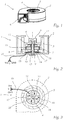
- Fig. 1 shows first the outer structure of a radial fan 1 of the subject type, wherein one recognizes a fan housing 2, fan blades 3, a rotor shaft 4 and an air outlet opening 5 .
- a rotor 8 associated with the stator 8 is held by means of a stator 9 in the housing 2 and it has stator windings 10, which are arranged on a multi-part armature 11 of conductive sheet metal, for example, a laminated sheet package. Furthermore, the stator has a plurality of pole shoes 12 , in the present case, which interact with the permanent magnets 7 of the rotor 6. The rotor 6 is rotatably supported by bearings 13 in the stator 8.
- a printed circuit board 14 is provided on which preferably not described in detail, the expert, however, known drive circuit 15 for the motor, namely for the stator windings 10, is provided and which via connecting lines 16 is connected to ground potential GND, as well as the two poles 0 and V CC of an operating voltage. From the circuit board 14 corresponding terminals 17 lead to the stator windings 10, wherein in the plan view of Fig. 3 detects that there are four terminals 17 corresponding to the number of pole shoes and the armature windings in this example.
- the invention further provides that at least one electrically conductive connection 18 is guided from the electrically conductive armature 11 of the stator 8 to at least one connection of the printed circuit board 14, not shown here, and this connection is connected to a fixed potential.
- This fixed potential may be the ground potential GND or one of the poles 0 or Vcc of the operating voltage.
- the electromagnetic interference generated by the drive circuit 15 in the stator windings 10 and radiated outward can be significantly reduced. Due to the connection of the armature 11 lying in the interior of the fan to an electrical potential of the drive circuit 15, the interference current is applied to the Drive circuit 15 is guided back and the electromagnetic interference of the motor windings is shielded.
- Fig. 4 shows the formation of the electrically conductive connection 18 as a resilient element, one end of which is fixedly connected to the armature 11 or a terminal of the printed circuit board 14 and the other end is pressed against a terminal of the printed circuit board or the anchor springs.
- the lower end in the drawing of a leaf spring 19 compound 18 is soldered, for example, to a not shown in detail Lötauge and the other, in the drawing upper end, pressed against the armature 11, so as to establish the electrical connection to a fixed potential manufacture.
- This design allows a quick and easy assembly of the fan.
- Fig. 5 shows another possibility of the embodiment of the electrically conductive connection 18, which here has a conductive coil spring 20 , which may also be guided in a sleeve 21 and one end - in the drawing, the lower end - firmly connected to a terminal on the circuit board 14 is, wherein the other end is pressed with a contact piece 22 against the armature 11.
- the respective spring element with one end to the armature 11 may be firmly connected, wherein the other end is resiliently pressed against contact on the circuit board 14.
- Fig. 6 schematically illustrates an embodiment in which the electrically conductive connection 18 from the electrically conductive armature 11 of the stator 8 to at least one terminal of the circuit board 14 comprises a piece of wire 23 , with its two ends, for example by soldering fixed to the armature 11 and a conductor portion is connected to the circuit board 14. Such a connection is particularly reliable.
- Fig. 7 is shown schematically that the armature 11 is connected via the electrically conductive connection 18 directly to a fixed potential, either GND or 0 or Vcc, whereas according to Fig. 8 the electrically conductive connection 18 a capacitor C. via which it is connected to a fixed potential, either GND or 0 or Vcc.
- Fig. 9 shows a variant in which the armature 11 is connected via a first capacitor C1 to the potential of the operating voltage Vcc and via a second capacitor C2 to ground potential GND.
- the 8 and 9 illustrate that the term "electrically conductive" for compound 18 also includes an AC-transmissive compound, which is particularly recommended if galvanic isolation of the armature from a fixed potential is desired.
- AC-transmissive compound which is particularly recommended if galvanic isolation of the armature from a fixed potential is desired. Which connection variant is to be used depends on the specific embodiment of the fan as such and on the other hand on the drive circuit and the source of the operating voltage, the most favorable connection 18 often being determined empirically.
- the Applicant has measured the interference of a commercial radial fan of the subject type with a Spektrumanalyzer over a frequency range of 150 kHz to 3 MHz with and without the inventive connection of the armature to a fixed potential and found that the invention provides a reduction of the interference of 10 to 15 dB.
Landscapes
- Engineering & Computer Science (AREA)
- Mechanical Engineering (AREA)
- General Engineering & Computer Science (AREA)
- Power Engineering (AREA)
- Physics & Mathematics (AREA)
- Electromagnetism (AREA)
- Structures Of Non-Positive Displacement Pumps (AREA)
- Motor Or Generator Frames (AREA)
- Permanent Magnet Type Synchronous Machine (AREA)
Abstract
Description
- Die Erfindung bezieht sich auf einen Radiallüfter mit einem Außenläufermotor und einem Gehäuse, welcher aufweist: einen Stator mit einem mehrere Polschuhe und Statorwicklungen umfassenden Anker, einen Rotor, welcher den Stator von außen umfasst und der Permanentmagnete und außen liegenden Lüfterflügel sowie eine in dem Stator drehbar gelagerte Rotorwelle besitzt, und eine in Abstand von den Statorwicklungen angeordnete Leiterplatte für eine Ansteuerschaltung des Außenläufermotors vorgesehen ist, von welcher Anschlussleitungen zu den Statorwicklungen führen.
- Lüfter dieser Art sind beispielsweise in Scheinwerfern von Kraftfahrzeugen eingebaut, um vor allem die verwendeten Leuchtmittel, wie LEDs oder Laserdioden und /oder deren elektronische Ansteuerungen zu kühlen. Die Ankerwicklungen der Außenläufermotoren solcher Lüfter werden üblicherweise über eine geeignete Schaltung auf der Leiterplatte angesteuert, wobei die Ansteuerungsströme oft steilflankig sind und dementsprechend elektromagnetische Störungen erzeugen, welche andere Komponenten schädlich beeinflussen können. Aus diesem Grund und auch wegen bestehender Vorschriften müssen abgestrahlte Störungen auf möglichst geringe Werte beschränkt werden.
- Es liegt nahe, einen Störer als solchen völlig zu schirmen, doch ist dies gerade bei einem Lüfter nicht realisierbar, wozu erschwerend hinzukommt, dass viele Lüfter teilweise oder zu großen Teilen aus nicht leitendem Kunststoff bestehen.
- Es ist daher eine Aufgabe der Erfindung, bei einem Radiallüfter der gegenständlichen Art eine Lösung zu finden, welche von dem Motor ausgehende Störstrahlung so gut wie möglich verringert.
- Diese Aufgabe wird mit einem Radiallüfter der eingangsgenannten Art erfindungsgemäß dadurch gelöst, dass zumindest eine elektrisch leitende Verbindung von dem elektrisch leitfähigen Anker des Stators zu zumindest einem Anschluss der Leiterplatte geführt ist und dieser Anschluss mit einem festen Potential der Ansteuerschaltung verbunden ist.
- Dabei ist es in vielen Fällen zweckmäßig, wenn das feste Potential der Ansteuerschaltung Massepotential ist.
- In anderen Fällen kann mit Vorteil vorgesehen sein, dass das feste Potential der Ansteuerschaltung ein Pol der Versorgungsspannung ist.
- Eine weitere oft zweckmäßige Variante der Erfindung, die eine oft unerwünschte galvanische Verbindung vermeidet, sieht vor, dass der elektrisch leitfähige Anker des Stators über einen Kondensator mit Massepotential und/oder der Betriebsspannung verbunden ist.
- Im Sinne eines einfachen Zusammenbaus des Radiallüfters kann es vorteilhaft sein, wenn die elektrisch leitende Verbindung als federndes Element ausgebildet ist, dessen eines Ende mit dem Anker oder einem Anschluss der Leiterplatte fest verbunden ist und dessen anderes Ende federnd gegen einen Anschluss der Leiterplatte oder den Anker gepresst ist.
- Falls der Rotor und/oder das Gehäuse zumindest abschnittsweise aus Kunststoff besteht, zeigt sich die Erfindung besonders wirksam.
- Die Erfindung samt weiteren Vorteilen ist im Folgenden an Hand beispielsweiser Ausführungsformen näher erläutert, die in der Zeichnung veranschaulicht sind. In dieser zeigen
-
Fig. 1 eine perspektivische Ansicht eines Radiallüfters nach der Erfindung, -
Fig. 2 einen schematischen Axialschnitt durch einen Radiallüfter nach der Erfindung, -
Fig. 3 eine schematische Unteransicht eines Radiallüfters nach der Erfindung, -
Fig. 4 bis Fig. 6 in einer geschnittenen Teilansicht drei verschiedene Ausbildungen einer elektrisch leitenden Verbindung von dem elektrisch leitfähigen Anker zu einem Anschluss der Leiterplatte und -
Fig. 7 bis 9 in schematischen Schaltbildern drei verschiedene Möglichkeiten der elektrischen Anbindung des Ankers an ein festes Potential. -
Fig. 1 zeigt zunächst den äußeren Aufbau eines Radiallüfters 1 der gegenständlichen Art, wobei man ein Lüftergehäuse 2, Lüfterschaufeln 3, eine Rotorwelle 4 und eine Luftaustrittsöffnung 5 erkennt. - Der weitere Aufbau des Radiallüfters 1 geht nun aus den
Fig. 2 und Fig. 3 hervor, welche zeigen, dass die Lüfterflügel 3 zu einem Rotor 6 gehören, der um die Rotorwelle 4 rotieren kann, und der an seinem inneren Umfang eine Anzahl von Permanentmagneten 7 besitzt. - Ein dem Rotor 6 zugeordneter Stator 8 ist mittels einer Statorhalterung 9 in dem Gehäuse 2 gehalten und er besitzt Statorwicklungen 10, die auf einem mehrteiligen Anker 11 aus leitfähigen Blech, beispielsweise ein Blechlammellenpaket, angeordnet sind. Weiters weist der Stator mehrere, im vorliegenden Fall vier Polschuhe 12 auf, die mit den Permanentmagneten 7 des Rotors 6 zusammenwirken. Der Rotor 6 ist mit Hilfe von Lagern 13 in dem Stator 8 drehbar gelagert.
- In Abstand von den Statorwicklungen 10 ist - in der Zeichnung unterhalb von diesen - eine Leiterplatte 14 vorgesehen, auf welcher bevorzugt die nicht näher beschriebene, dem Fachmann jedoch bekannte Ansteuerschaltung 15 für den Motor, nämlich für die Statorwicklungen 10, vorgesehen ist und welche über Anschlussleitungen 16 mit Massepotential GND, sowie den beiden Polen 0 und VCC einer Betriebsspannung verbunden ist. Von der Leiterplatte 14 führen entsprechende Anschlüsse 17 zu den Statorwicklungen 10, wobei man in der Draufsicht der
Fig. 3 erkennt, dass entsprechend der Anzahl der Polschuhe und der Ankerwicklungen bei diesem Beispiel vier Anschlüsse 17 vorhanden sind. - Die Erfindung sieht weiters vor, dass zumindest eine elektrisch leitende Verbindung 18 von dem elektrisch leitfähigen Anker 11 des Stators 8 zu zumindest einem, hier nicht näher gezeigten Anschluss der Leiterplatte 14 geführt ist und dieser Anschluss mit einem festen Potential verbunden ist. Dieses feste Potential kann das Massepotential GND oder auch einer der Pole 0 oder Vcc der Betriebsspannung sein.
- Dank dieser Maßnahme lassen sich die durch die Ansteuerschaltung 15 in den Statorwicklungen 10 erzeugten und nach außen abgestrahlten elektromagnetischen Störungen erheblich reduzieren. Durch die Anbindung des im Inneren des Lüfters liegenden Ankers 11 an ein elektrisches Potential der Ansteuerschaltung 15 wird der Störstrom auf die Ansteuerschaltung 15 zurück geführt und die elektromagnetische Störaussendung der Motorwicklungen wird dadurch abgeschirmt.
- An Hand der folgenden Figuren werden nun verschiedene Möglichkeiten der näheren Realisierung der Erfindung veranschaulicht.
-
Fig. 4 zeigt die Ausbildung der elektrisch leitende Verbindung 18 als federndes Element, dessen eines Ende mit dem Anker 11 oder einem Anschluss der Leiterplatte 14 fest verbunden ist und dessen anderes Ende federn gegen einen Anschluss der Leiterplatte oder den Anker gepresst ist. Im gezeigten Beispiel ist das in der Zeichnung untere Ende der eine Blattfeder 19 umfassenden Verbindung 18 beispielsweise an ein nicht näher gezeigtes Lötauge angelötet und das andere, in der Zeichnung obere Ende, gegen den Anker 11 gepresst, um so die elektrische Verbindung zu einem festen Potential herzustellen. Diese Ausbildung ermöglicht einen raschen und einfachen Zusammenbau des Lüfters. -
Fig. 5 zeigt eine andere Möglichkeit der Ausgestaltung der elektrisch leitende Verbindung 18, die hier eine leitende Spiralfeder 20 aufweist, die auch in einer Hülse 21 geführt sein kann und deren eines Ende - in der Zeichnung das untere Ende - mit einem Anschluss an der Leiterplatte 14 fest verbunden ist, wobei das andere Ende mit einem Kontaktstück 22 gegen den Anker 11 gepresst ist. - In den beiden Fällen der
Fig. 4 und 5 kann natürlich auch das jeweilige Federelement mit einem Ende mit dem Anker 11 fest verbunden sein, wobei das andere Ende federnd gegen einen Kontakt auf der Leiterplatte 14 gedrückt wird. -
Fig. 6 veranschaulicht schematisch eine Ausführung, bei welcher die elektrisch leitende Verbindung 18 von dem elektrisch leitfähigen Anker 11 des Stators 8 zu zumindest einem Anschluss der Leiterplatte 14 ein Drahtstück 23 umfasst, das mit seinen beiden Enden z.B. durch Löten fest mit dem Anker 11 bzw. einem Leiterabschnitt auf der Leiterplatte 14 verbunden ist. Eine solche Verbindung ist besonders zuverlässig. - In
Fig. 7 ist schematisch dargestellt, dass der Anker 11 über die elektrisch leitende Verbindung 18 direkt mit einem festen Potential, entweder GND oder 0 oder Vcc verbunden ist, wogegen gemäßFig. 8 die elektrisch leitende Verbindung 18 einen Kondensator C umfasst, über den sie mit einem festen Potential, entweder GND oder 0 oder Vcc verbunden ist. -
Fig. 9 zeigt eine Variante, bei welcher der Anker 11 über einen ersten Kondensator C1 mit dem Potential der Betriebsspannung Vcc und über einen zweiten Kondensator C2 mit Massepotential GND verbunden ist. - Die
Fig. 8 und 9 veranschaulichen, dass der Begriff "elektrisch leitend" für die Verbindung 18 auch eine nur für Wechselstrom durchlässige Verbindung umfasst, die sich besonders empfiehlt, falls eine galvanische Trennung des Ankers von einem festen Potential gewünscht ist. Welche Verbindungsvariante angewendet werden soll, richtet sich nach der spezifischen Ausführung einerseits des Lüfters als solchen und anderseits nach der Ansteuerschaltung und der Quelle der Betriebsspannung, wobei die günstigste Verbindung 18 oft empirisch zu bestimmen sein wird. - Die Anmelderin hat die Störstrahlung eines handelsüblichen Radiallüfters der gegenständlichen Bauart mit einem Spektrumanalyzer über einen Frequenzbereich von 150 kHz bis 3 MHz gemessen und zwar mit und ohne die erfindungsgemäße Anbindung des Ankers an ein festes Potential und festgestellt, dass die Erfindung eine Verminderung der Störstrahlung von 10 bis 15 dB ergibt.
Liste der Bezugszeichen 1 Radiallüfter 13 Lager C Kondensator 2 Gehäuse 14 Leiterplatte C1 Kondensator 3 Lüfterschaufeln 15 Ansteuerschaltung C2 Kondensator 4 Rotorwelle 16 Anschlussleitungen GND Potential 5 Luftaustrittsöffiiung 17 Anschlüsse VCC Potential 6 Rotor 18 Verbindung 0 Potential 7 Permanentmagnete 19 Blattfeder 8 Stator 20 Spiralfeder 9 Statorhalterung 21 Hülse 10 Statorwicklungen 22 Kontaktstück 11 Anker 23 Drahtstück 12 Polschuhe
Claims (6)
- Radiallüfter (1) mit einem Außenläufermotor (6+8) und einem Gehäuse (2), welcher aufweist:einen Stator (8) mit einem mehrere Polschuhe (12) und Statorwicklungen (10) umfassenden Anker (11),einen Rotor (6), welcher den Stator von außen umfasst und der Permanentmagnete (7) und außen liegenden Lüfterflügel (3) sowie eine in dem Stator drehbar gelagerte Rotorwelle (4) besitzt,und eine in Abstand von den Statorwicklungen angeordnete Leiterplatte (14) vorgesehen ist, von welcher Anschlussleitungen von einer Betriebsspannung und Masse zu den Statorwicklungen führen,dadurch gekennzeichnet, dasszumindest eine elektrisch leitende Verbindung (18) von dem elektrisch leitfähige Anker (11) des Stators (8) zu zumindest einem Anschluss der Leiterplatte (14) geführt ist und dieser Anschluss mit einem festen Potential (GND, 0, Vcc) verbunden ist.
- Radiallüfter (1) nach Anspruch 1, dadurch gekennzeichnet, dass das feste Potential Massepotential (GND) ist.
- Radiallüfter (1) nach Anspruch 1, dadurch gekennzeichnet, dass das feste Potential ein Pol (0, Vcc) der Betriebsspannung ist.
- Radiallüfter (1) nach einem der Ansprüche 1 bis 3, dadurch gekennzeichnet, dass der elektrisch leitfähigen Anker (11) des Stators (8) über einen Kondensator (C, C1, C2) mit Massepotential (GND) und/oder einem Pol (0, Vcc) der Betriebsspannung verbunden ist.
- Radiallüfter (1) nach einem der Ansprüche 1 bis 4, dadurch gekennzeichnet, dass die elektrisch leitende Verbindung (18) als federndes Element ausgebildet ist, dessen eines Ende mit dem Anker (11) oder einem Anschluss der Leiterplatte (14) fest verbunden ist und dessen anderes Ende federnd gegen einen Anschluss der Leiterplatte oder den Anker gepresst ist.
- Radiallüfter (1) nach einem der Ansprüche 1 bis 5, dadurch gekennzeichnet, dass der Rotor (6) und/oder das Gehäuse (2) zumindest abschnittsweise aus Kunststoff besteht.
Priority Applications (3)
| Application Number | Priority Date | Filing Date | Title |
|---|---|---|---|
| EP17198073.3A EP3477829B1 (de) | 2017-10-24 | 2017-10-24 | Radiallüfter mit einem aussenläufermotor |
| KR1020180123569A KR102115796B1 (ko) | 2017-10-24 | 2018-10-17 | 외부 로터 모터를 갖는 레이디얼 팬 |
| CN201811243365.1A CN109695592B (zh) | 2017-10-24 | 2018-10-24 | 带有外转子电机的离心式通风机 |
Applications Claiming Priority (1)
| Application Number | Priority Date | Filing Date | Title |
|---|---|---|---|
| EP17198073.3A EP3477829B1 (de) | 2017-10-24 | 2017-10-24 | Radiallüfter mit einem aussenläufermotor |
Publications (2)
| Publication Number | Publication Date |
|---|---|
| EP3477829A1 true EP3477829A1 (de) | 2019-05-01 |
| EP3477829B1 EP3477829B1 (de) | 2023-08-02 |
Family
ID=60162146
Family Applications (1)
| Application Number | Title | Priority Date | Filing Date |
|---|---|---|---|
| EP17198073.3A Active EP3477829B1 (de) | 2017-10-24 | 2017-10-24 | Radiallüfter mit einem aussenläufermotor |
Country Status (3)
| Country | Link |
|---|---|
| EP (1) | EP3477829B1 (de) |
| KR (1) | KR102115796B1 (de) |
| CN (1) | CN109695592B (de) |
Cited By (1)
| Publication number | Priority date | Publication date | Assignee | Title |
|---|---|---|---|---|
| WO2021018669A1 (de) * | 2019-08-01 | 2021-02-04 | Vitesco Technologies GmbH | Spülluftpumpe und fahrzeug |
Families Citing this family (1)
| Publication number | Priority date | Publication date | Assignee | Title |
|---|---|---|---|---|
| TWI783824B (zh) * | 2021-12-14 | 2022-11-11 | 赫德實驗有限公司 | 具有定子接地機構的馬達及其定子接地機構 |
Citations (5)
| Publication number | Priority date | Publication date | Assignee | Title |
|---|---|---|---|---|
| EP1154546A2 (de) * | 2000-05-11 | 2001-11-14 | ebm Werke GmbH & Co. KG | Stator eines Aussenläufermotors mit Schutzleiter-Anschlussteil |
| DE202009006871U1 (de) * | 2008-05-20 | 2009-10-15 | Ebm-Papst St. Georgen Gmbh & Co. Kg | Elektromotor |
| WO2013098309A2 (de) * | 2011-12-29 | 2013-07-04 | Robert Bosch Gmbh | Vorrichtung zum schirmen von elektromagnetischer störstrahlung eines elektromotors |
| DE102013108506A1 (de) * | 2013-08-07 | 2015-02-12 | Ebm-Papst St. Georgen Gmbh & Co. Kg | Außenläufermotor mit einem Radiallüfterrad |
| WO2015197574A1 (de) * | 2014-06-26 | 2015-12-30 | Brose Fahrzeugteile GmbH & Co. Kommanditgesellschaft, Würzburg | Elektrische maschine |
Family Cites Families (2)
| Publication number | Priority date | Publication date | Assignee | Title |
|---|---|---|---|---|
| DE10158963A1 (de) * | 2001-11-30 | 2003-06-18 | Ziehl Abegg Ag | Außenläufermotor |
| ES2607841T3 (es) * | 2009-03-25 | 2017-04-04 | Ebm-Papst Mulfingen Gmbh & Co. Kg | Ventilador radial |
-
2017
- 2017-10-24 EP EP17198073.3A patent/EP3477829B1/de active Active
-
2018
- 2018-10-17 KR KR1020180123569A patent/KR102115796B1/ko not_active Expired - Fee Related
- 2018-10-24 CN CN201811243365.1A patent/CN109695592B/zh active Active
Patent Citations (5)
| Publication number | Priority date | Publication date | Assignee | Title |
|---|---|---|---|---|
| EP1154546A2 (de) * | 2000-05-11 | 2001-11-14 | ebm Werke GmbH & Co. KG | Stator eines Aussenläufermotors mit Schutzleiter-Anschlussteil |
| DE202009006871U1 (de) * | 2008-05-20 | 2009-10-15 | Ebm-Papst St. Georgen Gmbh & Co. Kg | Elektromotor |
| WO2013098309A2 (de) * | 2011-12-29 | 2013-07-04 | Robert Bosch Gmbh | Vorrichtung zum schirmen von elektromagnetischer störstrahlung eines elektromotors |
| DE102013108506A1 (de) * | 2013-08-07 | 2015-02-12 | Ebm-Papst St. Georgen Gmbh & Co. Kg | Außenläufermotor mit einem Radiallüfterrad |
| WO2015197574A1 (de) * | 2014-06-26 | 2015-12-30 | Brose Fahrzeugteile GmbH & Co. Kommanditgesellschaft, Würzburg | Elektrische maschine |
Cited By (1)
| Publication number | Priority date | Publication date | Assignee | Title |
|---|---|---|---|---|
| WO2021018669A1 (de) * | 2019-08-01 | 2021-02-04 | Vitesco Technologies GmbH | Spülluftpumpe und fahrzeug |
Also Published As
| Publication number | Publication date |
|---|---|
| CN109695592A (zh) | 2019-04-30 |
| EP3477829B1 (de) | 2023-08-02 |
| KR102115796B1 (ko) | 2020-05-28 |
| KR20190045844A (ko) | 2019-05-03 |
| CN109695592B (zh) | 2021-04-13 |
Similar Documents
| Publication | Publication Date | Title |
|---|---|---|
| EP1689065B1 (de) | Stator eines Elektromotors und Verfahren zu seiner Herstellung | |
| DE69601270T2 (de) | Getriebemotor, insbesondere zum Antrieb eines Kraftfahrzeug-Scheibenwischers | |
| DE102010049577B4 (de) | Endkappenanordnung | |
| DE102013104823A1 (de) | Elektromotor | |
| DE102016223844B4 (de) | Elektromotor und Kühlerlüftermodul mit einem solchen Elektromotor | |
| EP0666424A1 (de) | Lüfter mit einem Lüfterrad | |
| DE102012208847A1 (de) | Elektronisch kommutierter Gleichstrommotor mit Abschirmung | |
| DE102012201545A1 (de) | Vorrichtung zum Schirmen von elektromagnetischer Störstrahlung eines Elektromotors | |
| EP2143190B1 (de) | Elektromotor | |
| DE102017215377A1 (de) | Statoreinheit, motor und lüftermotor | |
| DE102021208084A1 (de) | Elektrische Maschine mit einer ein Statorgehäuse kontaktierenden Elektronikplatine | |
| WO2008098681A1 (de) | Bürstenkommutierter elektromotor | |
| DE102017216250A1 (de) | Antrieb eines Kraftfahrzeugs | |
| EP3477829B1 (de) | Radiallüfter mit einem aussenläufermotor | |
| DE202009006871U1 (de) | Elektromotor | |
| DE102016201312A1 (de) | Pumpeneinrichtung | |
| DE102014201491B4 (de) | Kreiselpumpenmotor | |
| DE202020005555U1 (de) | Elektrische Maschine mit einer elektrisch leitenden Abschirmplatte | |
| DE102016219635A1 (de) | Nebenaggregat | |
| DE102005007611A1 (de) | Elektromotor mit Entstörvorrichtung | |
| DE102016222563A1 (de) | Elektrische Maschine | |
| WO2005046031A1 (de) | Elektrische kommutatorläufer-maschine mit entstörfilter | |
| DE3522835A1 (de) | Aggregat zum foerdern von kraftstoff | |
| DE102022207439A1 (de) | Elektronikmodul | |
| DE102021201099A1 (de) | Befestigungsanordnung eines leiterplattenmontierten Bauelements |
Legal Events
| Date | Code | Title | Description |
|---|---|---|---|
| PUAI | Public reference made under article 153(3) epc to a published international application that has entered the european phase |
Free format text: ORIGINAL CODE: 0009012 |
|
| STAA | Information on the status of an ep patent application or granted ep patent |
Free format text: STATUS: THE APPLICATION HAS BEEN PUBLISHED |
|
| AK | Designated contracting states |
Kind code of ref document: A1 Designated state(s): AL AT BE BG CH CY CZ DE DK EE ES FI FR GB GR HR HU IE IS IT LI LT LU LV MC MK MT NL NO PL PT RO RS SE SI SK SM TR |
|
| AX | Request for extension of the european patent |
Extension state: BA ME |
|
| STAA | Information on the status of an ep patent application or granted ep patent |
Free format text: STATUS: REQUEST FOR EXAMINATION WAS MADE |
|
| 17P | Request for examination filed |
Effective date: 20190913 |
|
| RBV | Designated contracting states (corrected) |
Designated state(s): AL AT BE BG CH CY CZ DE DK EE ES FI FR GB GR HR HU IE IS IT LI LT LU LV MC MK MT NL NO PL PT RO RS SE SI SK SM TR |
|
| STAA | Information on the status of an ep patent application or granted ep patent |
Free format text: STATUS: EXAMINATION IS IN PROGRESS |
|
| 17Q | First examination report despatched |
Effective date: 20211004 |
|
| GRAP | Despatch of communication of intention to grant a patent |
Free format text: ORIGINAL CODE: EPIDOSNIGR1 |
|
| STAA | Information on the status of an ep patent application or granted ep patent |
Free format text: STATUS: GRANT OF PATENT IS INTENDED |
|
| INTG | Intention to grant announced |
Effective date: 20230425 |
|
| GRAS | Grant fee paid |
Free format text: ORIGINAL CODE: EPIDOSNIGR3 |
|
| GRAA | (expected) grant |
Free format text: ORIGINAL CODE: 0009210 |
|
| STAA | Information on the status of an ep patent application or granted ep patent |
Free format text: STATUS: THE PATENT HAS BEEN GRANTED |
|
| AK | Designated contracting states |
Kind code of ref document: B1 Designated state(s): AL AT BE BG CH CY CZ DE DK EE ES FI FR GB GR HR HU IE IS IT LI LT LU LV MC MK MT NL NO PL PT RO RS SE SI SK SM TR |
|
| REG | Reference to a national code |
Ref country code: GB Ref legal event code: FG4D Free format text: NOT ENGLISH |
|
| REG | Reference to a national code |
Ref country code: CH Ref legal event code: EP |
|
| REG | Reference to a national code |
Ref country code: DE Ref legal event code: R096 Ref document number: 502017015133 Country of ref document: DE |
|
| REG | Reference to a national code |
Ref country code: IE Ref legal event code: FG4D Free format text: LANGUAGE OF EP DOCUMENT: GERMAN |
|
| REG | Reference to a national code |
Ref country code: LT Ref legal event code: MG9D |
|
| REG | Reference to a national code |
Ref country code: NL Ref legal event code: MP Effective date: 20230802 |
|
| PG25 | Lapsed in a contracting state [announced via postgrant information from national office to epo] |
Ref country code: GR Free format text: LAPSE BECAUSE OF FAILURE TO SUBMIT A TRANSLATION OF THE DESCRIPTION OR TO PAY THE FEE WITHIN THE PRESCRIBED TIME-LIMIT Effective date: 20231103 |
|
| PG25 | Lapsed in a contracting state [announced via postgrant information from national office to epo] |
Ref country code: IS Free format text: LAPSE BECAUSE OF FAILURE TO SUBMIT A TRANSLATION OF THE DESCRIPTION OR TO PAY THE FEE WITHIN THE PRESCRIBED TIME-LIMIT Effective date: 20231202 |
|
| PG25 | Lapsed in a contracting state [announced via postgrant information from national office to epo] |
Ref country code: SE Free format text: LAPSE BECAUSE OF FAILURE TO SUBMIT A TRANSLATION OF THE DESCRIPTION OR TO PAY THE FEE WITHIN THE PRESCRIBED TIME-LIMIT Effective date: 20230802 Ref country code: RS Free format text: LAPSE BECAUSE OF FAILURE TO SUBMIT A TRANSLATION OF THE DESCRIPTION OR TO PAY THE FEE WITHIN THE PRESCRIBED TIME-LIMIT Effective date: 20230802 Ref country code: PT Free format text: LAPSE BECAUSE OF FAILURE TO SUBMIT A TRANSLATION OF THE DESCRIPTION OR TO PAY THE FEE WITHIN THE PRESCRIBED TIME-LIMIT Effective date: 20231204 Ref country code: NO Free format text: LAPSE BECAUSE OF FAILURE TO SUBMIT A TRANSLATION OF THE DESCRIPTION OR TO PAY THE FEE WITHIN THE PRESCRIBED TIME-LIMIT Effective date: 20231102 Ref country code: NL Free format text: LAPSE BECAUSE OF FAILURE TO SUBMIT A TRANSLATION OF THE DESCRIPTION OR TO PAY THE FEE WITHIN THE PRESCRIBED TIME-LIMIT Effective date: 20230802 Ref country code: LV Free format text: LAPSE BECAUSE OF FAILURE TO SUBMIT A TRANSLATION OF THE DESCRIPTION OR TO PAY THE FEE WITHIN THE PRESCRIBED TIME-LIMIT Effective date: 20230802 Ref country code: LT Free format text: LAPSE BECAUSE OF FAILURE TO SUBMIT A TRANSLATION OF THE DESCRIPTION OR TO PAY THE FEE WITHIN THE PRESCRIBED TIME-LIMIT Effective date: 20230802 Ref country code: IS Free format text: LAPSE BECAUSE OF FAILURE TO SUBMIT A TRANSLATION OF THE DESCRIPTION OR TO PAY THE FEE WITHIN THE PRESCRIBED TIME-LIMIT Effective date: 20231202 Ref country code: HR Free format text: LAPSE BECAUSE OF FAILURE TO SUBMIT A TRANSLATION OF THE DESCRIPTION OR TO PAY THE FEE WITHIN THE PRESCRIBED TIME-LIMIT Effective date: 20230802 Ref country code: GR Free format text: LAPSE BECAUSE OF FAILURE TO SUBMIT A TRANSLATION OF THE DESCRIPTION OR TO PAY THE FEE WITHIN THE PRESCRIBED TIME-LIMIT Effective date: 20231103 Ref country code: FI Free format text: LAPSE BECAUSE OF FAILURE TO SUBMIT A TRANSLATION OF THE DESCRIPTION OR TO PAY THE FEE WITHIN THE PRESCRIBED TIME-LIMIT Effective date: 20230802 |
|
| PG25 | Lapsed in a contracting state [announced via postgrant information from national office to epo] |
Ref country code: PL Free format text: LAPSE BECAUSE OF FAILURE TO SUBMIT A TRANSLATION OF THE DESCRIPTION OR TO PAY THE FEE WITHIN THE PRESCRIBED TIME-LIMIT Effective date: 20230802 |
|
| PG25 | Lapsed in a contracting state [announced via postgrant information from national office to epo] |
Ref country code: ES Free format text: LAPSE BECAUSE OF FAILURE TO SUBMIT A TRANSLATION OF THE DESCRIPTION OR TO PAY THE FEE WITHIN THE PRESCRIBED TIME-LIMIT Effective date: 20230802 |
|
| PG25 | Lapsed in a contracting state [announced via postgrant information from national office to epo] |
Ref country code: SM Free format text: LAPSE BECAUSE OF FAILURE TO SUBMIT A TRANSLATION OF THE DESCRIPTION OR TO PAY THE FEE WITHIN THE PRESCRIBED TIME-LIMIT Effective date: 20230802 Ref country code: RO Free format text: LAPSE BECAUSE OF FAILURE TO SUBMIT A TRANSLATION OF THE DESCRIPTION OR TO PAY THE FEE WITHIN THE PRESCRIBED TIME-LIMIT Effective date: 20230802 Ref country code: ES Free format text: LAPSE BECAUSE OF FAILURE TO SUBMIT A TRANSLATION OF THE DESCRIPTION OR TO PAY THE FEE WITHIN THE PRESCRIBED TIME-LIMIT Effective date: 20230802 Ref country code: EE Free format text: LAPSE BECAUSE OF FAILURE TO SUBMIT A TRANSLATION OF THE DESCRIPTION OR TO PAY THE FEE WITHIN THE PRESCRIBED TIME-LIMIT Effective date: 20230802 Ref country code: DK Free format text: LAPSE BECAUSE OF FAILURE TO SUBMIT A TRANSLATION OF THE DESCRIPTION OR TO PAY THE FEE WITHIN THE PRESCRIBED TIME-LIMIT Effective date: 20230802 Ref country code: CZ Free format text: LAPSE BECAUSE OF FAILURE TO SUBMIT A TRANSLATION OF THE DESCRIPTION OR TO PAY THE FEE WITHIN THE PRESCRIBED TIME-LIMIT Effective date: 20230802 Ref country code: SK Free format text: LAPSE BECAUSE OF FAILURE TO SUBMIT A TRANSLATION OF THE DESCRIPTION OR TO PAY THE FEE WITHIN THE PRESCRIBED TIME-LIMIT Effective date: 20230802 |
|
| REG | Reference to a national code |
Ref country code: DE Ref legal event code: R097 Ref document number: 502017015133 Country of ref document: DE |
|
| PG25 | Lapsed in a contracting state [announced via postgrant information from national office to epo] |
Ref country code: IT Free format text: LAPSE BECAUSE OF FAILURE TO SUBMIT A TRANSLATION OF THE DESCRIPTION OR TO PAY THE FEE WITHIN THE PRESCRIBED TIME-LIMIT Effective date: 20230802 Ref country code: MC Free format text: LAPSE BECAUSE OF FAILURE TO SUBMIT A TRANSLATION OF THE DESCRIPTION OR TO PAY THE FEE WITHIN THE PRESCRIBED TIME-LIMIT Effective date: 20230802 |
|
| REG | Reference to a national code |
Ref country code: CH Ref legal event code: PL |
|
| PLBE | No opposition filed within time limit |
Free format text: ORIGINAL CODE: 0009261 |
|
| STAA | Information on the status of an ep patent application or granted ep patent |
Free format text: STATUS: NO OPPOSITION FILED WITHIN TIME LIMIT |
|
| P01 | Opt-out of the competence of the unified patent court (upc) registered |
Effective date: 20240506 |
|
| REG | Reference to a national code |
Ref country code: BE Ref legal event code: MM Effective date: 20231031 |
|
| PG25 | Lapsed in a contracting state [announced via postgrant information from national office to epo] |
Ref country code: LU Free format text: LAPSE BECAUSE OF NON-PAYMENT OF DUE FEES Effective date: 20231024 |
|
| PG25 | Lapsed in a contracting state [announced via postgrant information from national office to epo] |
Ref country code: LU Free format text: LAPSE BECAUSE OF NON-PAYMENT OF DUE FEES Effective date: 20231024 |
|
| 26N | No opposition filed |
Effective date: 20240503 |
|
| PG25 | Lapsed in a contracting state [announced via postgrant information from national office to epo] |
Ref country code: CH Free format text: LAPSE BECAUSE OF NON-PAYMENT OF DUE FEES Effective date: 20231031 |
|
| GBPC | Gb: european patent ceased through non-payment of renewal fee |
Effective date: 20231102 |
|
| PG25 | Lapsed in a contracting state [announced via postgrant information from national office to epo] |
Ref country code: CH Free format text: LAPSE BECAUSE OF NON-PAYMENT OF DUE FEES Effective date: 20231031 Ref country code: SI Free format text: LAPSE BECAUSE OF FAILURE TO SUBMIT A TRANSLATION OF THE DESCRIPTION OR TO PAY THE FEE WITHIN THE PRESCRIBED TIME-LIMIT Effective date: 20230802 |
|
| PG25 | Lapsed in a contracting state [announced via postgrant information from national office to epo] |
Ref country code: BE Free format text: LAPSE BECAUSE OF NON-PAYMENT OF DUE FEES Effective date: 20231031 |
|
| PG25 | Lapsed in a contracting state [announced via postgrant information from national office to epo] |
Ref country code: IE Free format text: LAPSE BECAUSE OF NON-PAYMENT OF DUE FEES Effective date: 20231024 |
|
| PG25 | Lapsed in a contracting state [announced via postgrant information from national office to epo] |
Ref country code: GB Free format text: LAPSE BECAUSE OF NON-PAYMENT OF DUE FEES Effective date: 20231102 |
|
| PG25 | Lapsed in a contracting state [announced via postgrant information from national office to epo] |
Ref country code: IE Free format text: LAPSE BECAUSE OF NON-PAYMENT OF DUE FEES Effective date: 20231024 Ref country code: GB Free format text: LAPSE BECAUSE OF NON-PAYMENT OF DUE FEES Effective date: 20231102 |
|
| PG25 | Lapsed in a contracting state [announced via postgrant information from national office to epo] |
Ref country code: BG Free format text: LAPSE BECAUSE OF FAILURE TO SUBMIT A TRANSLATION OF THE DESCRIPTION OR TO PAY THE FEE WITHIN THE PRESCRIBED TIME-LIMIT Effective date: 20230802 |
|
| PG25 | Lapsed in a contracting state [announced via postgrant information from national office to epo] |
Ref country code: BG Free format text: LAPSE BECAUSE OF FAILURE TO SUBMIT A TRANSLATION OF THE DESCRIPTION OR TO PAY THE FEE WITHIN THE PRESCRIBED TIME-LIMIT Effective date: 20230802 |
|
| REG | Reference to a national code |
Ref country code: AT Ref legal event code: MM01 Ref document number: 1595943 Country of ref document: AT Kind code of ref document: T Effective date: 20231024 |
|
| PG25 | Lapsed in a contracting state [announced via postgrant information from national office to epo] |
Ref country code: AT Free format text: LAPSE BECAUSE OF NON-PAYMENT OF DUE FEES Effective date: 20231024 |
|
| PG25 | Lapsed in a contracting state [announced via postgrant information from national office to epo] |
Ref country code: AT Free format text: LAPSE BECAUSE OF NON-PAYMENT OF DUE FEES Effective date: 20231024 |
|
| REG | Reference to a national code |
Ref country code: DE Ref legal event code: R084 Ref document number: 502017015133 Country of ref document: DE |
|
| PG25 | Lapsed in a contracting state [announced via postgrant information from national office to epo] |
Ref country code: CY Free format text: LAPSE BECAUSE OF FAILURE TO SUBMIT A TRANSLATION OF THE DESCRIPTION OR TO PAY THE FEE WITHIN THE PRESCRIBED TIME-LIMIT; INVALID AB INITIO Effective date: 20171024 |
|
| PG25 | Lapsed in a contracting state [announced via postgrant information from national office to epo] |
Ref country code: HU Free format text: LAPSE BECAUSE OF FAILURE TO SUBMIT A TRANSLATION OF THE DESCRIPTION OR TO PAY THE FEE WITHIN THE PRESCRIBED TIME-LIMIT; INVALID AB INITIO Effective date: 20171024 |
|
| PG25 | Lapsed in a contracting state [announced via postgrant information from national office to epo] |
Ref country code: TR Free format text: LAPSE BECAUSE OF FAILURE TO SUBMIT A TRANSLATION OF THE DESCRIPTION OR TO PAY THE FEE WITHIN THE PRESCRIBED TIME-LIMIT Effective date: 20230802 |
|
| PGFP | Annual fee paid to national office [announced via postgrant information from national office to epo] |
Ref country code: DE Payment date: 20251020 Year of fee payment: 9 |
|
| PGFP | Annual fee paid to national office [announced via postgrant information from national office to epo] |
Ref country code: FR Payment date: 20251027 Year of fee payment: 9 |