EP3477734A1 - Composite explosion-proof valve, cover plate assembly, and battery - Google Patents
Composite explosion-proof valve, cover plate assembly, and battery Download PDFInfo
- Publication number
- EP3477734A1 EP3477734A1 EP17833515.4A EP17833515A EP3477734A1 EP 3477734 A1 EP3477734 A1 EP 3477734A1 EP 17833515 A EP17833515 A EP 17833515A EP 3477734 A1 EP3477734 A1 EP 3477734A1
- Authority
- EP
- European Patent Office
- Prior art keywords
- explosion
- proof
- valve according
- compound
- flame
- Prior art date
- Legal status (The legal status is an assumption and is not a legal conclusion. Google has not performed a legal analysis and makes no representation as to the accuracy of the status listed.)
- Withdrawn
Links
- 239000002131 composite material Substances 0.000 title 1
- 239000012528 membrane Substances 0.000 claims abstract description 179
- 150000001875 compounds Chemical class 0.000 claims abstract description 76
- RNFJDJUURJAICM-UHFFFAOYSA-N 2,2,4,4,6,6-hexaphenoxy-1,3,5-triaza-2$l^{5},4$l^{5},6$l^{5}-triphosphacyclohexa-1,3,5-triene Chemical group N=1P(OC=2C=CC=CC=2)(OC=2C=CC=CC=2)=NP(OC=2C=CC=CC=2)(OC=2C=CC=CC=2)=NP=1(OC=1C=CC=CC=1)OC1=CC=CC=C1 RNFJDJUURJAICM-UHFFFAOYSA-N 0.000 claims abstract description 33
- 239000012757 flame retardant agent Substances 0.000 claims description 45
- 238000003466 welding Methods 0.000 claims description 30
- 239000000463 material Substances 0.000 claims description 12
- 239000003795 chemical substances by application Substances 0.000 claims description 10
- 239000012796 inorganic flame retardant Substances 0.000 claims description 10
- 230000002093 peripheral effect Effects 0.000 claims description 7
- IJGRMHOSHXDMSA-UHFFFAOYSA-N Atomic nitrogen Chemical compound N#N IJGRMHOSHXDMSA-UHFFFAOYSA-N 0.000 claims description 6
- OAICVXFJPJFONN-UHFFFAOYSA-N Phosphorus Chemical compound [P] OAICVXFJPJFONN-UHFFFAOYSA-N 0.000 claims description 6
- WNROFYMDJYEPJX-UHFFFAOYSA-K aluminium hydroxide Chemical compound [OH-].[OH-].[OH-].[Al+3] WNROFYMDJYEPJX-UHFFFAOYSA-K 0.000 claims description 6
- ADCOVFLJGNWWNZ-UHFFFAOYSA-N antimony trioxide Chemical compound O=[Sb]O[Sb]=O ADCOVFLJGNWWNZ-UHFFFAOYSA-N 0.000 claims description 6
- 229910052736 halogen Inorganic materials 0.000 claims description 6
- 239000000843 powder Substances 0.000 claims description 6
- 239000007787 solid Substances 0.000 claims description 6
- OKTJSMMVPCPJKN-UHFFFAOYSA-N Carbon Chemical compound [C] OKTJSMMVPCPJKN-UHFFFAOYSA-N 0.000 claims description 3
- 229920000049 Carbon (fiber) Polymers 0.000 claims description 3
- 239000002033 PVDF binder Substances 0.000 claims description 3
- XUIMIQQOPSSXEZ-UHFFFAOYSA-N Silicon Chemical compound [Si] XUIMIQQOPSSXEZ-UHFFFAOYSA-N 0.000 claims description 3
- 239000004917 carbon fiber Substances 0.000 claims description 3
- 229910002804 graphite Inorganic materials 0.000 claims description 3
- 239000010439 graphite Substances 0.000 claims description 3
- 150000002367 halogens Chemical class 0.000 claims description 3
- VTHJTEIRLNZDEV-UHFFFAOYSA-L magnesium dihydroxide Chemical compound [OH-].[OH-].[Mg+2] VTHJTEIRLNZDEV-UHFFFAOYSA-L 0.000 claims description 3
- 229910001862 magnesium hydroxide Inorganic materials 0.000 claims description 3
- 239000000347 magnesium hydroxide Substances 0.000 claims description 3
- 239000007769 metal material Substances 0.000 claims description 3
- VNWKTOKETHGBQD-UHFFFAOYSA-N methane Chemical compound C VNWKTOKETHGBQD-UHFFFAOYSA-N 0.000 claims description 3
- 239000003094 microcapsule Substances 0.000 claims description 3
- 229910052757 nitrogen Inorganic materials 0.000 claims description 3
- 229910052755 nonmetal Inorganic materials 0.000 claims description 3
- 229910052698 phosphorus Inorganic materials 0.000 claims description 3
- 239000011574 phosphorus Substances 0.000 claims description 3
- 229910001285 shape-memory alloy Inorganic materials 0.000 claims description 3
- 229910052710 silicon Inorganic materials 0.000 claims description 3
- 239000010703 silicon Substances 0.000 claims description 3
- 229920002981 polyvinylidene fluoride Polymers 0.000 claims description 2
- QVGXLLKOCUKJST-UHFFFAOYSA-N atomic oxygen Chemical compound [O] QVGXLLKOCUKJST-UHFFFAOYSA-N 0.000 abstract description 10
- 238000004880 explosion Methods 0.000 abstract description 10
- 229910052760 oxygen Inorganic materials 0.000 abstract description 10
- 239000001301 oxygen Substances 0.000 abstract description 10
- 238000002485 combustion reaction Methods 0.000 abstract description 7
- 230000002950 deficient Effects 0.000 abstract description 7
- 230000002159 abnormal effect Effects 0.000 abstract description 6
- 230000009471 action Effects 0.000 abstract description 3
- 239000007789 gas Substances 0.000 description 12
- 239000007774 positive electrode material Substances 0.000 description 6
- MYMOFIZGZYHOMD-UHFFFAOYSA-N Dioxygen Chemical compound O=O MYMOFIZGZYHOMD-UHFFFAOYSA-N 0.000 description 5
- 229910001882 dioxygen Inorganic materials 0.000 description 5
- 238000002347 injection Methods 0.000 description 4
- 239000007924 injection Substances 0.000 description 4
- 239000007788 liquid Substances 0.000 description 4
- HBBGRARXTFLTSG-UHFFFAOYSA-N Lithium ion Chemical compound [Li+] HBBGRARXTFLTSG-UHFFFAOYSA-N 0.000 description 3
- 239000004698 Polyethylene Substances 0.000 description 3
- 239000004721 Polyphenylene oxide Substances 0.000 description 3
- -1 Polypropylene Polymers 0.000 description 3
- 239000004743 Polypropylene Substances 0.000 description 3
- 230000006870 function Effects 0.000 description 3
- 238000010438 heat treatment Methods 0.000 description 3
- 229910001416 lithium ion Inorganic materials 0.000 description 3
- 238000004519 manufacturing process Methods 0.000 description 3
- 239000005020 polyethylene terephthalate Substances 0.000 description 3
- 229920000139 polyethylene terephthalate Polymers 0.000 description 3
- 229920006380 polyphenylene oxide Polymers 0.000 description 3
- PXHVJJICTQNCMI-UHFFFAOYSA-N Nickel Chemical compound [Ni] PXHVJJICTQNCMI-UHFFFAOYSA-N 0.000 description 2
- 238000005336 cracking Methods 0.000 description 2
- 238000011161 development Methods 0.000 description 2
- 230000004907 flux Effects 0.000 description 2
- 238000004026 adhesive bonding Methods 0.000 description 1
- 229910052782 aluminium Inorganic materials 0.000 description 1
- XAGFODPZIPBFFR-UHFFFAOYSA-N aluminium Chemical compound [Al] XAGFODPZIPBFFR-UHFFFAOYSA-N 0.000 description 1
- 230000009286 beneficial effect Effects 0.000 description 1
- 229910052799 carbon Inorganic materials 0.000 description 1
- 238000005260 corrosion Methods 0.000 description 1
- 230000007797 corrosion Effects 0.000 description 1
- 238000002788 crimping Methods 0.000 description 1
- 238000010586 diagram Methods 0.000 description 1
- 230000000694 effects Effects 0.000 description 1
- 238000004146 energy storage Methods 0.000 description 1
- 238000005516 engineering process Methods 0.000 description 1
- 239000011888 foil Substances 0.000 description 1
- 230000006872 improvement Effects 0.000 description 1
- 238000001746 injection moulding Methods 0.000 description 1
- 238000000034 method Methods 0.000 description 1
- 230000004048 modification Effects 0.000 description 1
- 238000012986 modification Methods 0.000 description 1
- 229910052759 nickel Inorganic materials 0.000 description 1
- 229920000573 polyethylene Polymers 0.000 description 1
- 229920001155 polypropylene Polymers 0.000 description 1
- 230000008569 process Effects 0.000 description 1
- 238000011160 research Methods 0.000 description 1
- 239000000243 solution Substances 0.000 description 1
- 238000012360 testing method Methods 0.000 description 1
- 238000004804 winding Methods 0.000 description 1
Images


Classifications
-
- H—ELECTRICITY
- H01—ELECTRIC ELEMENTS
- H01M—PROCESSES OR MEANS, e.g. BATTERIES, FOR THE DIRECT CONVERSION OF CHEMICAL ENERGY INTO ELECTRICAL ENERGY
- H01M50/00—Constructional details or processes of manufacture of the non-active parts of electrochemical cells other than fuel cells, e.g. hybrid cells
- H01M50/30—Arrangements for facilitating escape of gases
- H01M50/383—Flame arresting or ignition-preventing means
-
- F—MECHANICAL ENGINEERING; LIGHTING; HEATING; WEAPONS; BLASTING
- F16—ENGINEERING ELEMENTS AND UNITS; GENERAL MEASURES FOR PRODUCING AND MAINTAINING EFFECTIVE FUNCTIONING OF MACHINES OR INSTALLATIONS; THERMAL INSULATION IN GENERAL
- F16K—VALVES; TAPS; COCKS; ACTUATING-FLOATS; DEVICES FOR VENTING OR AERATING
- F16K17/00—Safety valves; Equalising valves, e.g. pressure relief valves
- F16K17/003—Safety valves; Equalising valves, e.g. pressure relief valves reacting to pressure and temperature
-
- F—MECHANICAL ENGINEERING; LIGHTING; HEATING; WEAPONS; BLASTING
- F16—ENGINEERING ELEMENTS AND UNITS; GENERAL MEASURES FOR PRODUCING AND MAINTAINING EFFECTIVE FUNCTIONING OF MACHINES OR INSTALLATIONS; THERMAL INSULATION IN GENERAL
- F16K—VALVES; TAPS; COCKS; ACTUATING-FLOATS; DEVICES FOR VENTING OR AERATING
- F16K7/00—Diaphragm valves or cut-off apparatus, e.g. with a member deformed, but not moved bodily, to close the passage ; Pinch valves
- F16K7/12—Diaphragm valves or cut-off apparatus, e.g. with a member deformed, but not moved bodily, to close the passage ; Pinch valves with flat, dished, or bowl-shaped diaphragm
-
- H—ELECTRICITY
- H01—ELECTRIC ELEMENTS
- H01M—PROCESSES OR MEANS, e.g. BATTERIES, FOR THE DIRECT CONVERSION OF CHEMICAL ENERGY INTO ELECTRICAL ENERGY
- H01M10/00—Secondary cells; Manufacture thereof
- H01M10/42—Methods or arrangements for servicing or maintenance of secondary cells or secondary half-cells
- H01M10/4235—Safety or regulating additives or arrangements in electrodes, separators or electrolyte
-
- H—ELECTRICITY
- H01—ELECTRIC ELEMENTS
- H01M—PROCESSES OR MEANS, e.g. BATTERIES, FOR THE DIRECT CONVERSION OF CHEMICAL ENERGY INTO ELECTRICAL ENERGY
- H01M50/00—Constructional details or processes of manufacture of the non-active parts of electrochemical cells other than fuel cells, e.g. hybrid cells
- H01M50/10—Primary casings; Jackets or wrappings
- H01M50/147—Lids or covers
-
- H—ELECTRICITY
- H01—ELECTRIC ELEMENTS
- H01M—PROCESSES OR MEANS, e.g. BATTERIES, FOR THE DIRECT CONVERSION OF CHEMICAL ENERGY INTO ELECTRICAL ENERGY
- H01M50/00—Constructional details or processes of manufacture of the non-active parts of electrochemical cells other than fuel cells, e.g. hybrid cells
- H01M50/30—Arrangements for facilitating escape of gases
- H01M50/342—Non-re-sealable arrangements
- H01M50/3425—Non-re-sealable arrangements in the form of rupturable membranes or weakened parts, e.g. pierced with the aid of a sharp member
-
- H—ELECTRICITY
- H01—ELECTRIC ELEMENTS
- H01M—PROCESSES OR MEANS, e.g. BATTERIES, FOR THE DIRECT CONVERSION OF CHEMICAL ENERGY INTO ELECTRICAL ENERGY
- H01M2200/00—Safety devices for primary or secondary batteries
-
- H—ELECTRICITY
- H01—ELECTRIC ELEMENTS
- H01M—PROCESSES OR MEANS, e.g. BATTERIES, FOR THE DIRECT CONVERSION OF CHEMICAL ENERGY INTO ELECTRICAL ENERGY
- H01M2200/00—Safety devices for primary or secondary batteries
- H01M2200/10—Temperature sensitive devices
-
- H—ELECTRICITY
- H01—ELECTRIC ELEMENTS
- H01M—PROCESSES OR MEANS, e.g. BATTERIES, FOR THE DIRECT CONVERSION OF CHEMICAL ENERGY INTO ELECTRICAL ENERGY
- H01M2200/00—Safety devices for primary or secondary batteries
- H01M2200/20—Pressure-sensitive devices
-
- Y—GENERAL TAGGING OF NEW TECHNOLOGICAL DEVELOPMENTS; GENERAL TAGGING OF CROSS-SECTIONAL TECHNOLOGIES SPANNING OVER SEVERAL SECTIONS OF THE IPC; TECHNICAL SUBJECTS COVERED BY FORMER USPC CROSS-REFERENCE ART COLLECTIONS [XRACs] AND DIGESTS
- Y02—TECHNOLOGIES OR APPLICATIONS FOR MITIGATION OR ADAPTATION AGAINST CLIMATE CHANGE
- Y02E—REDUCTION OF GREENHOUSE GAS [GHG] EMISSIONS, RELATED TO ENERGY GENERATION, TRANSMISSION OR DISTRIBUTION
- Y02E60/00—Enabling technologies; Technologies with a potential or indirect contribution to GHG emissions mitigation
- Y02E60/10—Energy storage using batteries
Definitions
- the present disclosure relates to the field of batteries, and particularly relates to a compound explosion-proof valve mounted on a battery cover plate assembly, a cover plate assembly containing the explosion-proof valve, and a battery.
- batteries are widely applied to vehicles, energy storage devices, electronic products and other devices, and furthermore, more and more people pay attention to the safety of the batteries.
- the internal gas pressure of the battery significantly increases, and if measures are not taken in time, explosion of the battery may be caused.
- a pressure-controlled explosion-proof valve (or referred to as safety valve) is mounted on a battery cover plate.
- the existing pressure-controlled explosion-proof valve generally includes one or more layers of pressure-controlled explosion-proof membranes. When the internal gas pressure of the battery exceeds an opening pressure of the explosion-proof valve, the explosion-proof valve is opened to release the combustible gas inside the battery so as to prevent battery explosion.
- the inventor of the present disclosure finds that for some batteries with the pressure-controlled explosion-proof valve structure, especially for a lithium ion battery of a ternary positive electrode material, when an internal temperature of the battery reaches a thermal runaway temperature of the positive electrode material of the battery, the battery is out of control, but the internal pressure of the battery is still smaller, and the pressure-controlled explosion-proof valve cannot be started; then, after 3-5 seconds of temperature rise, the temperature rises rapidly, and the internal pressure rises rapidly; at this moment, although the pressure-controlled explosion-proof valve with one or more layers of pressure-controlled explosion-proof membranes is arranged, a large amount of combustible gas produced inside the battery is rapidly ejected from the pressure-controlled explosion-proof valve, and the risk of battery combustion or explosion still exists.
- the present disclosure aims to resolve at least one of the technical problems existing in the prior art. Therefore, the present disclosure provides a compound explosion-proof valve, a cover plate assembly, and a battery.
- a first aspect of the present disclosure provides a compound explosion-proof valve, including at least two layers of explosion-proof membranes and a flame-retardant structure located between the at least two layers of explosion-proof membranes.
- the compound explosion-proof valve further includes a base body; the base body is provided with a pressure relief hole, and the at least two layers of explosion-proof membranes are respectively mounted at two ends of the pressure relief hole; and the flame-retardant structure is arranged in the pressure relief hole between the at least two layers of explosion-proof membranes.
- the explosion-proof membrane is a pressure-controlled explosion-proof membrane.
- an opening pressure of the pressure-controlled explosion-proof membrane is 0.1-2 MPa.
- the opening pressure of the pressure-controlled explosion-proof membrane is 0.2-0.8 MPa.
- the explosion-proof membrane is a temperature-controlled explosion-proof membrane.
- an opening temperature of the temperature-controlled explosion-proof membrane is 100-200 °C.
- the opening temperature of the temperature-controlled explosion-proof membrane is 100-150 °C.
- the at least two layers of explosion-proof membranes include a pressure-controlled explosion-proof membrane mounted at an outer end of the pressure relief hole and a temperature-controlled explosion-proof membrane mounted at an inner end of the pressure relief hole.
- the at least two layers of explosion-proof membranes include a pressure-controlled explosion-proof membrane mounted at an inner end of the pressure relief hole and a temperature-controlled explosion-proof membrane mounted at an outer end of the pressure relief hole.
- a stepped bottom mounting step is formed at a lower end of the base body, and one layer of explosion-proof membrane is mounted in the bottom mounting step; and a stepped top mounting step is formed at an upper end of the base body, and the other layer of explosion-proof membrane is mounted in the top mounting step.
- a mounting part is formed at a peripheral edge of the temperature-controlled explosion-proof membrane, a framework is embedded in the mounting part, and a central part of the temperature-controlled explosion-proof membrane is provided with an opening region.
- the opening region is integrally press-thinned or gradually thinned relative to the mounting part.
- a material of the temperature-controlled explosion-proof membrane is a non-metal material.
- the material of the temperature-controlled explosion-proof membrane is one of PP, PE, PPO, PET, or PVDF.
- the framework is a carbon fiber framework or a memory alloy framework.
- a thickness of the mounting part of the temperature-controlled explosion-proof membrane is 0.2-5 mm.
- a thickness of the mounting part of the temperature-controlled explosion-proof membrane is 0.5-2 mm.
- the opening region of the temperature-controlled explosion-proof membrane is in a cross shape, a thickness of the opening region is 0.02-3 mm, and a width of the opening region is 0.3-10 mm.
- the thickness of the opening region of the temperature-controlled explosion-proof membrane is 0.05-0.15 mm, and the width of the opening region is 1-5 mm.
- an inner part of the flame-retardant structure includes a gap.
- the flame-retardant structure contains a flame-retardant agent.
- the flame-retardant agent is in a form of solid powder
- the flame-retardant structure is formed by compressing and ramming the flame-retardant agent in the form of solid powder.
- the flame-retardant structure is a microcapsule containing the flame-retardant agent.
- the flame-retardant agent is configured as an organic flame-retardant agent, an inorganic flame-retardant agent, or a mixed flame-retardant agent formed by mixing the inorganic flame-retardant agent with the organic flame-retardant agent.
- the organic flame-retardant agent includes one or more of a halogen-based flame-retardant agent, a phosphorus-based flame-retardant agent, a nitrogen-based flame-retardant agent, and a phosphorus-halogen-based flame-retardant agent.
- the inorganic flame-retardant agent includes one or more of antimonous oxide, magnesium hydroxide, aluminum hydroxide, or silicon-based oxide.
- the mixed flame-retardant agent includes red phosphorus, aluminum hydroxide, and expanded graphite.
- the explosion-proof membrane is a pressure-controlled explosion-proof membrane
- the pressure-controlled explosion-proof membrane includes a welding parts at a peripheral edge and a pressure opening part in the middle, and the welding part is welded in the top mounting step.
- the pressure opening part of the pressure-controlled explosion-proof membrane is provided with an explosion-proof notch.
- the pressure opening part of the pressure-controlled explosion-proof membrane is further provided with a flexible buffer structure, so that cracking or breaking of the explosion-proof notch caused by shrinkage of two sides of a welding seam during laser welding can be effectively avoided so as to ensure a finished product ratio of the explosion-proof valve in a manufacturing process. Furthermore, by adopting the above flexible buffer structure, the uniformity and reliability of the starting pressure of the explosion-proof valve can be greatly improved, and the fatigue resistance of the explosion-proof valve can also be well improved.
- the flexible buffer structure is arranged between a welding seam between the welding part and the top mounting step and the explosion-proof notch.
- the flexible buffer structure is annular.
- the flexible buffer structure includes one or more wave crests and/or wave troughs.
- the flexible buffer structure includes one wave crest and one wave trough.
- a second aspect of the present disclosure further provides a cover plate assembly, including a cover plate body, and a compound explosion-proof valve is mounted on the cover plate body.
- a third aspect of the present disclosure provides a battery, including a shell, an electrode core and a cover plate assembly, the cover plate assembly and the shell form a sealed space, and the electrode core is mounted in the sealed space.
- the cover plate assembly of the battery is provided with the improved compound explosion-proof valve of the present disclosure; because at least two layers of explosion-proof membranes are mounted on the compound explosion-proof valve and the flame-retardant structure is arranged between the at least two layers of explosion-proof membranes, when the battery (such as internal temperature or internal pressure) is abnormal, the first layer of explosion-proof membrane is opened; under the action of the flame-retardant structure, the compound explosion-proof valve is in a local oxygen-deficient state, and it is difficult for a high-temperature combustible matter ejected from the battery to ignite under the local oxygen-deficient condition; therefore, the compound explosion-proof valve is capable of reliving pressure in time when the battery is abnormal and effectively isolating external oxygen from entering, thereby preventing occurrence of battery combustion and explosion and avoiding secondary disasters and larger abnormity.
- 1 cover plate body; 2. shell; 3. first electrode assembly; 4. second electrode assembly; 5. liquid injection hole cover; 6. compound explosion-proof valve; 60. base body; 61. first layer of explosion-proof membrane; 62. second layer of explosion-proof membrane; 63. flame-retardant structure; 601. base part; 602. lug boss part; 603. pressure relief hole; 604. top mounting step; 605. bottom mounting step; 610. welding part; 611. pressure opening part; 612. explosion-proof notch; 613. wave trough; 614. wave crest; 615. welding seam; 621. opening region; 622. mounting part; and 623. framework.
- a battery, a cover plate assembly, and a compound explosion-proof valve 6 provided by the present disclosure are specifically explained below.
- the present embodiment discloses a battery.
- the battery includes a shell 2, an electrode core, and a cover plate assembly, where the cover plate assembly and the shell 2 form a sealed space, and the electrode core is mounted in the sealed space.
- the battery in the present embodiment may be a lithium ion battery or may be another type of nickel battery or the like.
- the electrode core is formed by winding or superposing a positive electrode sheet, a diaphragm and a negative electrode sheet, which is known to the public.
- the cover plate assembly includes a cover plate body 1, and a compound explosion-proof valve 6 is mounted on the cover plate body 1.
- a first electrode assembly 3 and a second electrode assembly 4 which are different in polarity are further mounted on the cover plate assembly in an insulated mode.
- the first electrode assembly 3 includes a first electrode, a first insulating part, and the like, and the first electrode and the cover plate body 1 are insulated by the first insulating part.
- the second electrode assembly 4 includes a second electrode, a second insulating part, and the like, and the second electrode and the cover plate body 1 are insulated by the second insulating part.
- the first electrode is a positive electrode
- the second electrode is a negative electrode
- the second electrode is a positive electrode.
- the positive electrode is electrically connected to the positive electrode sheet of the electrode core
- the negative electrode is electrically connected to the negative electrode sheet of the electrode core.
- the cover plate body 1 is further provided with a liquid injection hole, and a liquid injection hole cover 5 covers the liquid injection hole.
- the compound explosion-proof valve 6 provided by the present embodiment includes a base body 60, a first layer of explosion-proof membrane 61, and a second layer of explosion-proof membrane 62; the base body 60 is provided with a pressure relief hole 603, and the second layer of explosion-proof membrane 62 and the first layer of explosion-proof membrane 61 are respectively mounted at two ends of the pressure relief hole 603; the first layer of explosion-proof membrane 61 is mounted at an outer end of the pressure relief hole 603, and the second layer of explosion-proof membrane 62 is mounted at an inner end of the pressure relief hole 603; and a flame-retardant structure 63 is arranged in the pressure relief hole 603 between the second layer of explosion-proof membrane 62 and the first layer of explosion-proof membrane 61.
- the base body 60 is configured to be welded with the cover plate body 1 (or the base body 60 may be mounted on the shell 2, and in the present embodiment, the base body 60 is mounted on the cover plate body 1 selectively), or the base body 60 may be subjected to integral punch forming with the cover plate body 1 to serve as a part of the cover plate body 1, namely, the base body 60 may be a structure independent of the cover plate body 1 or the shell 2, or may be integrally formed with the cover plate body 1 or the shell 2, in other words, the base body 60 of the compound explosion-proof valve 6 is formed as a part of the cover plate body 1 or the shell 2.
- the base body 60 includes a base part 601 and a lug boss part 602 protruding from the base part 601, and the pressure relief hole 603 is formed by upwards stretching from the center of the base part 601 to penetrate through the lug boss part 602.
- the base part 601 is configured to be welded with the cover plate body 1 (or the base part 601 may be mounted on the shell 2, and in the present embodiment, the base part 601 is mounted on the cover plate body 1 selectively), or the base part 601 may be subjected to integral punch forming with the cover plate body 1 to serve as a part of the cover plate body 1, namely, the base part 601 may be a structure independent of the cover plate body 1 or the shell 2, or may be integrally formed with the cover plate body 1 or the shell 2, in other words, the base part 601 of the compound explosion-proof valve 6 may be formed as a part of the cover plate body 1 or the shell 2.
- the first layer of explosion-proof membrane 61 and the second layer of explosion-proof membrane 62 may be a pressure-controlled explosion-proof membrane or a temperature-controlled explosion-proof membrane respectively, namely, both the first layer of explosion-proof membrane 61 and the second layer of explosion-proof membrane 62 may be pressure-controlled explosion-proof membranes; both the first layer of explosion-proof membrane 61 and the second layer of explosion-proof membrane 62 may be temperature-controlled explosion-proof membranes; the first layer of explosion-proof membrane 61 may be a pressure-controlled explosion-proof membrane, and the second layer of explosion-proof membrane 62 may be a temperature-controlled explosion-proof membrane; or the second layer of explosion-proof membrane 62 may be a pressure-controlled explosion-proof membrane, and the first layer of explosion-proof membrane 61 may be a temperature-controlled explosion-proof membrane.
- both the first layer of explosion-proof membrane 61 mounted at the outer end of the pressure relief hole 603 and the second layer of explosion-proof membrane 62 mounted at the inner end of the pressure relief hole 603 are temperature-controlled explosion-proof membranes.
- both the first layer of explosion-proof membrane 61 mounted at the outer end of the pressure relief hole 603 and the second layer of explosion-proof membrane 62 mounted at the inner end of the pressure relief hole 603 are pressure-controlled explosion-proof membranes.
- a pressure-controlled explosion-proof membrane is mounted at the outer end of the pressure relief hole 603, and a temperature-controlled explosion-proof membrane is mounted at the inner end of the pressure relief hole 603.
- An opening temperature of the temperature-controlled explosion-proof membrane is 100-200 °C.
- the opening temperature refers to a temperature at which the temperature-controlled explosion-proof membrane is heated and opened. When the temperature-controlled explosion-proof membrane is heated and the temperature reaches the opening temperature, the temperature-controlled explosion-proof membrane is opened.
- the opening temperature is lower than a thermal runaway temperature of a positive electrode material of the battery.
- the thermal runaway temperature of the positive electrode material of an existing lithium ion battery is 200-600 °C generally.
- Tests show that the effect is optimal when the opening temperature of the temperature-controlled explosion-proof membrane is 100-150 °C, and in the temperature range, the temperature-controlled explosion-proof membrane can not be opened in advance and can be ensured to be opened before thermal runaway of the positive electrode material of the battery.
- mounting parts 622 are formed at peripheral edges of the temperature-controlled explosion-proof membrane, a framework 623 is embedded in the mounting part 622, and a central part of the temperature-controlled explosion-proof membrane is provided with an opening region 621.
- the framework 623 is configured to support and fix the temperature-controlled explosion-proof membrane, and the framework 623 is a carbon fiber framework or a memory alloy framework.
- the framework 623 may be injection-molded in the base body 60 of the temperature-controlled explosion-proof membrane in a mode of injection molding, or the peripheral edge of the temperature-controlled explosion-proof membrane is overturned and covered to wrap and fix the framework 623 on the mounting part 622.
- the temperature-controlled explosion-proof membrane may be mounted in modes of gluing, crimping, welding, or the like. In this way, when the temperature is excessively high, the temperature-controlled explosion-proof membrane is heated to shrink, the opening region 621 is first pulled apart while the internal temperature rises, and then the mounting part 622 further shrinks by taking the framework 623 as a fixed point to enlarge an exhaust opening, so as to realize the function of opening the temperature-controlled explosion-proof membrane by heating.
- the opening region 621 is integrally press-thinned or gradually thinned relative to the mounting part 622.
- the opening region 621 may be formed in a cross shape as shown in Fig. 3 , or may be in a straight shape or any other suitable shape.
- a material of the temperature-controlled explosion-proof membrane is not specifically limited as long as the material is resistant to corrosion, is influenced by temperature and may be heated to shrink so as to open the temperature-controlled explosion-proof membrane when the temperature exceeds a preset temperature.
- a material of the temperature-controlled explosion-proof membrane is a non-metal material.
- the material of the temperature-controlled explosion-proof membrane is one of PP (Polypropylene), PE (Polyethylene), PPO (Polyphenylene Oxide), PET (Polyethylene Terephthalate), or PVDF (Polyvinylidene Fluoride).
- the thickness of the mounting part 622 of the temperature-controlled explosion-proof membrane is 0.2-5 mm.
- the thickness of the mounting part 622 of the temperature-controlled explosion-proof membrane is 0.5-2 mm.
- a thickness of the opening region 621 of the temperature-controlled explosion-proof membrane is 0.02-3 mm, and a width of the opening region 621 is 0.3-10 mm.
- the thickness of the opening region 621 of the temperature-controlled explosion-proof membrane is 0.05-0.15 mm, and a width of the cross shape in a preferred embodiment is 1-5 mm.
- a preferred opening pressure of the pressure-controlled explosion-proof membrane is 0.1-2 MPa.
- the opening pressure refers to a pressure at which the pressure-controlled explosion-proof membrane is pressed and opened; when the internal pressure of the battery is greater than the opening pressure, the pressure-controlled explosion-proof membrane is opened; and preferably, the opening pressure of the pressure-controlled explosion-proof membrane is 0.2-0.8 MPa.
- the pressure-controlled explosion-proof membrane includes welding parts 610 at peripheral edges and a pressure opening part 611 in the middle, and the welding part 610 is welded on the base body 60.
- the pressure opening part 611 of the pressure-controlled explosion-proof membrane is provided with explosion-proof notches 612.
- a welding seam 615 is formed between the welding part 610 and the base body 60, and the welding seam 615 is filled with welding flux to weld the pressure-controlled explosion-proof membrane on the base body 60.
- a stepped bottom mounting step 605 is formed at a lower end of the base body 60, and one layer of explosion-proof membrane is mounted in the bottom mounting step 605; and a stepped top mounting step 604 is formed at an upper end of the base body 60, and the other layer of explosion-proof membrane is mounted in the top mounting step 604.
- a material of the pressure-controlled explosion-proof membrane may be an aluminum foil well known by those skilled in the art, or may be another material well known by those skilled in the art.
- the pressure opening part 611 of the pressure-controlled explosion-proof membrane is also provided with a flexible buffer structure.
- the flexible buffer structure may effectively avoid cracking or breaking of the explosion-proof notches 612 caused by shrinkage of two sides of the welding seam 615 during laser welding, so as to ensure the finished product ratio of the explosion-proof valve in a manufacturing process.
- the uniformity and reliability of the starting pressure of the pressure-controlled explosion-proof membrane may be greatly improved, and the fatigue resistance of the pressure-controlled explosion-proof membrane can also be well improved.
- the flexible buffer structure is arranged between the welding seam 615 and the explosion-proof notch 612.
- the flexible buffer structure is annular.
- the flexible buffer structure is not specifically limited in structure, and the flexible buffer structure may include one or more wave crests 614 and/or wave troughs 613.
- the flexible buffer structure includes one wave crest 614 and one wave trough 613.
- a thickness of the welding part 610 of the pressure-controlled explosion-proof membrane is 0.2-0.8 mm, and a thickness of the pressure opening part 611 of the pressure-controlled explosion-proof membrane is 0.05-0.15 mm.
- a height difference between the wave crest 614 and the wave trough 613 and a surface of the pressure opening part is 1-8 times the thickness of the pressure opening part 611.
- the height difference herein refers to a distance between the highest point of the wave crest 614 and an upper surface of the pressure opening part 611 and a distance between the lowest point of the wave trough 613 and a lower surface of the pressure opening part 611.
- the specific structure and material of the flame-retardant structure 63 are not specifically limited as long as the structure and the material may ensure that internal combustible gas leaks out through the flame-retardant structure 63 in time and the flame-retardant structure 63 can form an oxygen-deficient state, so as to prevent external oxygen gas from entering.
- an inner part of the flame-retardant structure 63 includes a gap (or hole) and the like, so that under the condition that the internal pressure is larger, the combustible gas inside the battery may leak out through the gap in time, and oxygen gas difficultly enters the battery through the gap.
- the flame-retardant structure 63 contains a flame-retardant agent.
- the flame-retardant agent may be in a form of solid powder, and the flame-retardant structure 63 is formed by compressing and ramming the flame-retardant agent in the form of solid powder.
- the flame-retardant structure is a microcapsule containing the flame-retardant agent.
- the flame-retardant agent may be configured as an organic flame-retardant agent, an inorganic flame-retardant agent, or a mixed flame-retardant agent formed by mixing the inorganic flame-retardant agent with the organic flame-retardant agent.
- the organic flame-retardant agent includes one or more of a halogen-based flame-retardant agent, a phosphorus-based flame-retardant agent, a nitrogen-based flame-retardant agent, and a phosphorus-halogen-based flame-retardant agent.
- the inorganic flame-retardant agent includes one or more of antimonous oxide, magnesium hydroxide, aluminum hydroxide, or silicon-based oxide.
- the mixed flame-retardant agent is formed by mixing the organic flame-retardant agent with the inorganic flame-retardant agent.
- the present embodiment provides an improved mixed flame-retardant agent, and the mixed flame-retardant agent includes red phosphorus, aluminum hydroxide, and expanded graphite.
- both the first layer of explosion-proof membrane 61 mounted at the outer end of the pressure relief hole 603 and the second layer of explosion-proof membrane 62 mounted at the inner end of the pressure relief hole 603 are temperature-controlled explosion-proof membranes.
- the stepped bottom mounting step 605 is formed at the lower end of the base body 60, and one layer of the temperature-controlled explosion-proof membrane is mounted in the bottom mounting step 605; and the stepped top mounting step 604 is formed at the upper end of the base body 60, and the other layer of temperature-controlled explosion-proof membrane is mounted in the top mounting step 604.
- a working principle of the battery with the compound explosion-proof valve 6 and provided by the present embodiment is described as follows: When the temperature rises due to abnormity inside the battery and combustible gas is produced inside the battery, and when the temperature rises to the opening temperature of the temperature-controlled explosion-proof membrane, the temperature-controlled explosion-proof valve is heated to shrink, the opening region 621 is first pulled apart, and then the mounting part 622 further shrinks by taking the framework 623 as the fixed point to enlarge the exhaust opening, so as to realize the function of opening the temperature-controlled explosion-proof membrane by heating. Because of the existence of the flame-retardant structure 63, a flame-retardant function is realized at the compound explosion-proof valve 6 to isolate external oxygen gas from entering the battery, thereby effectively preventing occurrence of battery combustion and explosion accidents.
- both the first layer of explosion-proof membrane 61 mounted at the outer end of the pressure relief hole 603 and the second layer of explosion-proof membrane 62 mounted at the inner end of the pressure relief hole 603 are pressure-controlled explosion-proof membranes.
- the stepped bottom mounting step 605 is formed at the lower end of the base body 60, and one layer of the pressure-controlled explosion-proof membrane is mounted in the bottom mounting step 605; and the stepped top mounting step 604 is formed at the upper end of the base body 60, and the other layer of pressure-controlled explosion-proof membrane is mounted in the top mounting step 604.
- a working principle of the battery with the compound explosion-proof valve 6 and provided by the present embodiment is described as follows: When the pressure rises due to abnormity inside the battery and the internal gas pressure increases to the opening pressure of the pressure-controlled explosion-proof membrane, the pressure-controlled explosion-proof membrane is opened from the explosion-proof notch 612. At this moment, because of the existence of the flame-retardant structure 63, the flame-retardant function is realized at the compound explosion-proof valve 6 to isolate external oxygen gas from entering the battery, thereby effectively preventing occurrence of battery combustion and explosion accidents.
- the first layer of explosion-proof membrane 61 mounted at the outer end of the pressure relief hole 603 is a pressure-controlled explosion-proof membrane
- the second layer of explosion-proof membrane 62 mounted at the inner end of the pressure relief hole 603 is a temperature-controlled explosion-proof membrane.
- the stepped bottom mounting step 605 is formed at the lower end of the base body 60, and the temperature-controlled explosion-proof membrane is mounted in the bottom mounting step 605; and the stepped top mounting step 604 is formed at the upper end of the base body 60, and the pressure-controlled explosion-proof membrane is mounted in the top mounting step 604.
- the welding part 610 is welded in the top mounting step 604, the welding seam 615 is formed between the welding part 610 and the top mounting step 604, and the welding seam 615 is filled with the welding flux to weld the pressure-controlled explosion-proof membrane 61 on the top mounting step 604.
- a working principle of the battery with the compound explosion-proof valve 6 and provided by the present embodiment is described as follows: When the temperature rises due to abnormity inside the battery and combustible gas is produced inside the battery, and when the temperature rises to the opening temperature of the temperature-controlled explosion-proof membrane, the temperature-controlled explosion-proof membrane is heated to shrink, the opening region 621 is first pulled apart while the internal temperature rises, and then the mounting part 622 further shrinks by taking the framework 623 as a fixed point to enlarge the exhaust opening, so as to realize the function of opening the temperature-controlled explosion-proof membrane by heating.
- the internal positive electrode material is not out of control, after 3-5 seconds, the internal temperature of the battery significantly rises, the internal gas pressure further increases, and when the internal gas pressure increases to the opening pressure of the pressure-controlled explosion-proof membrane, the pressure-controlled explosion-proof membrane is opened from the explosion-proof notch 612.
- a flame-retardant function is realized at the compound explosion-proof valve 6 to isolate external oxygen gas from entering the battery, thereby effectively preventing occurrence of battery combustion and explosion accidents.
- the compound explosion-proof valve 6 further includes a valve cover (not marked in the figures), and the valve cover is mounted on the base body 60 to be used for preventing the compound explosion-proof valve 6 from being damaged by an external force.
- the cover plate assembly of the battery is provided with the improved compound explosion-proof valve 6 of the present disclosure; because at least two layers of explosion-proof membranes are mounted on the compound explosion-proof valve 6 and the flame-retardant structure 63 is arranged between the two layers of explosion-proof membranes, when the battery is abnormal, the explosion-proof membrane is opened; under the action of the flame-retardant structure 63, the compound explosion-proof valve 6 is in a local oxygen-deficient state, and it is difficult for a high-temperature combustible matter ejected from the battery to ignite under the local oxygen-deficient condition; therefore, the compound explosion-proof valve is capable of relieving pressure in time when the battery is abnormal and effectively isolating external oxygen from entering, thereby preventing occurrence of battery combustion and explosion and avoiding secondary disasters and larger abnormity.
Landscapes
- Chemical & Material Sciences (AREA)
- Chemical Kinetics & Catalysis (AREA)
- Electrochemistry (AREA)
- General Chemical & Material Sciences (AREA)
- Engineering & Computer Science (AREA)
- General Engineering & Computer Science (AREA)
- Mechanical Engineering (AREA)
- Manufacturing & Machinery (AREA)
- Gas Exhaust Devices For Batteries (AREA)
- Fireproofing Substances (AREA)
- Electric Double-Layer Capacitors Or The Like (AREA)
- Safety Valves (AREA)
Abstract
Description
- The present disclosure relates to the field of batteries, and particularly relates to a compound explosion-proof valve mounted on a battery cover plate assembly, a cover plate assembly containing the explosion-proof valve, and a battery.
- With the gradual development of science and technology, batteries are widely applied to vehicles, energy storage devices, electronic products and other devices, and furthermore, more and more people pay attention to the safety of the batteries. When a battery has a fault and a large amount of combustible gas is produced in the battery, the internal gas pressure of the battery significantly increases, and if measures are not taken in time, explosion of the battery may be caused.
- Therefore, to prevent occurrence of battery explosion, generally, a pressure-controlled explosion-proof valve (or referred to as safety valve) is mounted on a battery cover plate. The existing pressure-controlled explosion-proof valve generally includes one or more layers of pressure-controlled explosion-proof membranes. When the internal gas pressure of the battery exceeds an opening pressure of the explosion-proof valve, the explosion-proof valve is opened to release the combustible gas inside the battery so as to prevent battery explosion. However, in battery research, development and production processes, the inventor of the present disclosure finds that for some batteries with the pressure-controlled explosion-proof valve structure, especially for a lithium ion battery of a ternary positive electrode material, when an internal temperature of the battery reaches a thermal runaway temperature of the positive electrode material of the battery, the battery is out of control, but the internal pressure of the battery is still smaller, and the pressure-controlled explosion-proof valve cannot be started; then, after 3-5 seconds of temperature rise, the temperature rises rapidly, and the internal pressure rises rapidly; at this moment, although the pressure-controlled explosion-proof valve with one or more layers of pressure-controlled explosion-proof membranes is arranged, a large amount of combustible gas produced inside the battery is rapidly ejected from the pressure-controlled explosion-proof valve, and the risk of battery combustion or explosion still exists.
- The present disclosure aims to resolve at least one of the technical problems existing in the prior art. Therefore, the present disclosure provides a compound explosion-proof valve, a cover plate assembly, and a battery.
- A first aspect of the present disclosure provides a compound explosion-proof valve, including at least two layers of explosion-proof membranes and a flame-retardant structure located between the at least two layers of explosion-proof membranes.
- Further, the compound explosion-proof valve further includes a base body; the base body is provided with a pressure relief hole, and the at least two layers of explosion-proof membranes are respectively mounted at two ends of the pressure relief hole; and the flame-retardant structure is arranged in the pressure relief hole between the at least two layers of explosion-proof membranes.
- Further, the explosion-proof membrane is a pressure-controlled explosion-proof membrane.
- Further, an opening pressure of the pressure-controlled explosion-proof membrane is 0.1-2 MPa.
- Further, the opening pressure of the pressure-controlled explosion-proof membrane is 0.2-0.8 MPa.
- Further, the explosion-proof membrane is a temperature-controlled explosion-proof membrane.
- Further, an opening temperature of the temperature-controlled explosion-proof membrane is 100-200 °C.
- Further, the opening temperature of the temperature-controlled explosion-proof membrane is 100-150 °C.
- Further, the at least two layers of explosion-proof membranes include a pressure-controlled explosion-proof membrane mounted at an outer end of the pressure relief hole and a temperature-controlled explosion-proof membrane mounted at an inner end of the pressure relief hole.
- Further, the at least two layers of explosion-proof membranes include a pressure-controlled explosion-proof membrane mounted at an inner end of the pressure relief hole and a temperature-controlled explosion-proof membrane mounted at an outer end of the pressure relief hole.
- Further, a stepped bottom mounting step is formed at a lower end of the base body, and one layer of explosion-proof membrane is mounted in the bottom mounting step; and a stepped top mounting step is formed at an upper end of the base body, and the other layer of explosion-proof membrane is mounted in the top mounting step.
- Further, a mounting part is formed at a peripheral edge of the temperature-controlled explosion-proof membrane, a framework is embedded in the mounting part, and a central part of the temperature-controlled explosion-proof membrane is provided with an opening region.
- Further, the opening region is integrally press-thinned or gradually thinned relative to the mounting part.
- Further, a material of the temperature-controlled explosion-proof membrane is a non-metal material.
- Further, the material of the temperature-controlled explosion-proof membrane is one of PP, PE, PPO, PET, or PVDF.
- Further, the framework is a carbon fiber framework or a memory alloy framework.
- Further, a thickness of the mounting part of the temperature-controlled explosion-proof membrane is 0.2-5 mm.
- Further, a thickness of the mounting part of the temperature-controlled explosion-proof membrane is 0.5-2 mm.
- Further, the opening region of the temperature-controlled explosion-proof membrane is in a cross shape, a thickness of the opening region is 0.02-3 mm, and a width of the opening region is 0.3-10 mm.
- Further, the thickness of the opening region of the temperature-controlled explosion-proof membrane is 0.05-0.15 mm, and the width of the opening region is 1-5 mm.
- Further, an inner part of the flame-retardant structure includes a gap.
- Further, the flame-retardant structure contains a flame-retardant agent.
- Further, the flame-retardant agent is in a form of solid powder, and the flame-retardant structure is formed by compressing and ramming the flame-retardant agent in the form of solid powder.
- Further, the flame-retardant structure is a microcapsule containing the flame-retardant agent.
- Further, the flame-retardant agent is configured as an organic flame-retardant agent, an inorganic flame-retardant agent, or a mixed flame-retardant agent formed by mixing the inorganic flame-retardant agent with the organic flame-retardant agent.
- Further, the organic flame-retardant agent includes one or more of a halogen-based flame-retardant agent, a phosphorus-based flame-retardant agent, a nitrogen-based flame-retardant agent, and a phosphorus-halogen-based flame-retardant agent.
- Further, the inorganic flame-retardant agent includes one or more of antimonous oxide, magnesium hydroxide, aluminum hydroxide, or silicon-based oxide.
- Further, the mixed flame-retardant agent includes red phosphorus, aluminum hydroxide, and expanded graphite.
- Further, the explosion-proof membrane is a pressure-controlled explosion-proof membrane, the pressure-controlled explosion-proof membrane includes a welding parts at a peripheral edge and a pressure opening part in the middle, and the welding part is welded in the top mounting step.
- Further, the pressure opening part of the pressure-controlled explosion-proof membrane is provided with an explosion-proof notch.
- Further, the pressure opening part of the pressure-controlled explosion-proof membrane is further provided with a flexible buffer structure, so that cracking or breaking of the explosion-proof notch caused by shrinkage of two sides of a welding seam during laser welding can be effectively avoided so as to ensure a finished product ratio of the explosion-proof valve in a manufacturing process. Furthermore, by adopting the above flexible buffer structure, the uniformity and reliability of the starting pressure of the explosion-proof valve can be greatly improved, and the fatigue resistance of the explosion-proof valve can also be well improved.
- Further, the flexible buffer structure is arranged between a welding seam between the welding part and the top mounting step and the explosion-proof notch.
- Further, the flexible buffer structure is annular.
- Further, the flexible buffer structure includes one or more wave crests and/or wave troughs.
- Further, the flexible buffer structure includes one wave crest and one wave trough.
- A second aspect of the present disclosure further provides a cover plate assembly, including a cover plate body, and a compound explosion-proof valve is mounted on the cover plate body.
- A third aspect of the present disclosure provides a battery, including a shell, an electrode core and a cover plate assembly, the cover plate assembly and the shell form a sealed space, and the electrode core is mounted in the sealed space.
- According to the battery, the cover plate assembly, and the compound explosion-proof valve provided by the present disclosure, the cover plate assembly of the battery is provided with the improved compound explosion-proof valve of the present disclosure; because at least two layers of explosion-proof membranes are mounted on the compound explosion-proof valve and the flame-retardant structure is arranged between the at least two layers of explosion-proof membranes, when the battery (such as internal temperature or internal pressure) is abnormal, the first layer of explosion-proof membrane is opened; under the action of the flame-retardant structure, the compound explosion-proof valve is in a local oxygen-deficient state, and it is difficult for a high-temperature combustible matter ejected from the battery to ignite under the local oxygen-deficient condition; therefore, the compound explosion-proof valve is capable of reliving pressure in time when the battery is abnormal and effectively isolating external oxygen from entering, thereby preventing occurrence of battery combustion and explosion and avoiding secondary disasters and larger abnormity.
-
-
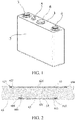
Fig. 1 is a three-dimensional schematic diagram of a battery provided in one specific embodiment of the present disclosure. -
Fig. 2 is a cross-sectional view of a compound explosion-proof valve provided in one specific embodiment of the present disclosure. -
Fig. 3 is a top view of a compound explosion-proof valve provided in one specific embodiment of the present disclosure. -
Fig. 4 is a cross-sectional view of a compound explosion-proof valve provided in another specific embodiment of the present disclosure. -
Fig. 5 is a cross-sectional view of a base body of a compound explosion-proof valve provided in one specific embodiment of the present disclosure. -
Fig. 6 is a cross-sectional view of a compound explosion-proof valve provided in another specific embodiment of the present disclosure. - In the
figures, 1 . cover plate body; 2. shell; 3. first electrode assembly; 4. second electrode assembly; 5. liquid injection hole cover; 6. compound explosion-proof valve; 60. base body; 61. first layer of explosion-proof membrane; 62. second layer of explosion-proof membrane; 63. flame-retardant structure; 601. base part; 602. lug boss part; 603. pressure relief hole; 604. top mounting step; 605. bottom mounting step; 610. welding part; 611. pressure opening part; 612. explosion-proof notch; 613. wave trough; 614. wave crest; 615. welding seam; 621. opening region; 622. mounting part; and 623. framework. - To make the technical problems to be solved by the present invention, technical solutions, and beneficial effects more comprehensible, the following further describes the present invention in detail with reference to the accompanying drawings and embodiments. It should be understood that the specific embodiments described herein are merely used for explaining the present disclosure instead of limiting the present disclosure.
- A battery, a cover plate assembly, and a compound explosion-proof valve 6 provided by the present disclosure are specifically explained below.
- As shown in
Fig. 1 , the present embodiment discloses a battery. The battery includes ashell 2, an electrode core, and a cover plate assembly, where the cover plate assembly and theshell 2 form a sealed space, and the electrode core is mounted in the sealed space. The battery in the present embodiment may be a lithium ion battery or may be another type of nickel battery or the like. The electrode core is formed by winding or superposing a positive electrode sheet, a diaphragm and a negative electrode sheet, which is known to the public. The cover plate assembly includes a cover plate body 1, and a compound explosion-proof valve 6 is mounted on the cover plate body 1. Generally, afirst electrode assembly 3 and asecond electrode assembly 4 which are different in polarity are further mounted on the cover plate assembly in an insulated mode. Generally, thefirst electrode assembly 3 includes a first electrode, a first insulating part, and the like, and the first electrode and the cover plate body 1 are insulated by the first insulating part. Generally, thesecond electrode assembly 4 includes a second electrode, a second insulating part, and the like, and the second electrode and the cover plate body 1 are insulated by the second insulating part. When the first electrode is a positive electrode, the second electrode is a negative electrode; and otherwise, when the first electrode is a negative electrode, the second electrode is a positive electrode. The positive electrode is electrically connected to the positive electrode sheet of the electrode core, and the negative electrode is electrically connected to the negative electrode sheet of the electrode core. Generally, the cover plate body 1 is further provided with a liquid injection hole, and a liquidinjection hole cover 5 covers the liquid injection hole. - Because the present disclosure does not improve the structure other than the compound explosion-proof valve 6 on the cover plate assembly of the battery, only the structure of the compound explosion-proof valve 6 is specifically explained below.
- As shown in
Fig. 2 andFig. 4 toFig. 6 , the compound explosion-proof valve 6 provided by the present embodiment includes abase body 60, a first layer of explosion-proof membrane 61, and a second layer of explosion-proof membrane 62; thebase body 60 is provided with apressure relief hole 603, and the second layer of explosion-proof membrane 62 and the first layer of explosion-proof membrane 61 are respectively mounted at two ends of thepressure relief hole 603; the first layer of explosion-proof membrane 61 is mounted at an outer end of thepressure relief hole 603, and the second layer of explosion-proof membrane 62 is mounted at an inner end of thepressure relief hole 603; and a flame-retardant structure 63 is arranged in thepressure relief hole 603 between the second layer of explosion-proof membrane 62 and the first layer of explosion-proof membrane 61. - The
base body 60 is configured to be welded with the cover plate body 1 (or thebase body 60 may be mounted on theshell 2, and in the present embodiment, thebase body 60 is mounted on the cover plate body 1 selectively), or thebase body 60 may be subjected to integral punch forming with the cover plate body 1 to serve as a part of the cover plate body 1, namely, thebase body 60 may be a structure independent of the cover plate body 1 or theshell 2, or may be integrally formed with the cover plate body 1 or theshell 2, in other words, thebase body 60 of the compound explosion-proof valve 6 is formed as a part of the cover plate body 1 or theshell 2. - In some embodiments of the present disclosure, as shown in
Fig. 5 and Fig. 6 , thebase body 60 includes abase part 601 and alug boss part 602 protruding from thebase part 601, and thepressure relief hole 603 is formed by upwards stretching from the center of thebase part 601 to penetrate through thelug boss part 602. Thebase part 601 is configured to be welded with the cover plate body 1 (or thebase part 601 may be mounted on theshell 2, and in the present embodiment, thebase part 601 is mounted on the cover plate body 1 selectively), or thebase part 601 may be subjected to integral punch forming with the cover plate body 1 to serve as a part of the cover plate body 1, namely, thebase part 601 may be a structure independent of the cover plate body 1 or theshell 2, or may be integrally formed with the cover plate body 1 or theshell 2, in other words, thebase part 601 of the compound explosion-proof valve 6 may be formed as a part of the cover plate body 1 or theshell 2. - The first layer of explosion-
proof membrane 61 and the second layer of explosion-proof membrane 62 may be a pressure-controlled explosion-proof membrane or a temperature-controlled explosion-proof membrane respectively, namely, both the first layer of explosion-proof membrane 61 and the second layer of explosion-proof membrane 62 may be pressure-controlled explosion-proof membranes; both the first layer of explosion-proof membrane 61 and the second layer of explosion-proof membrane 62 may be temperature-controlled explosion-proof membranes; the first layer of explosion-proof membrane 61 may be a pressure-controlled explosion-proof membrane, and the second layer of explosion-proof membrane 62 may be a temperature-controlled explosion-proof membrane; or the second layer of explosion-proof membrane 62 may be a pressure-controlled explosion-proof membrane, and the first layer of explosion-proof membrane 61 may be a temperature-controlled explosion-proof membrane. - For example, as shown in
Fig. 2 , both the first layer of explosion-proof membrane 61 mounted at the outer end of thepressure relief hole 603 and the second layer of explosion-proof membrane 62 mounted at the inner end of thepressure relief hole 603 are temperature-controlled explosion-proof membranes. As shown inFig. 4 , both the first layer of explosion-proof membrane 61 mounted at the outer end of thepressure relief hole 603 and the second layer of explosion-proof membrane 62 mounted at the inner end of thepressure relief hole 603 are pressure-controlled explosion-proof membranes. As shown inFig. 6 , a pressure-controlled explosion-proof membrane is mounted at the outer end of thepressure relief hole 603, and a temperature-controlled explosion-proof membrane is mounted at the inner end of thepressure relief hole 603. - An opening temperature of the temperature-controlled explosion-proof membrane is 100-200 °C. The opening temperature refers to a temperature at which the temperature-controlled explosion-proof membrane is heated and opened. When the temperature-controlled explosion-proof membrane is heated and the temperature reaches the opening temperature, the temperature-controlled explosion-proof membrane is opened. The opening temperature is lower than a thermal runaway temperature of a positive electrode material of the battery. The thermal runaway temperature of the positive electrode material of an existing lithium ion battery is 200-600 °C generally. Tests show that the effect is optimal when the opening temperature of the temperature-controlled explosion-proof membrane is 100-150 °C, and in the temperature range, the temperature-controlled explosion-proof membrane can not be opened in advance and can be ensured to be opened before thermal runaway of the positive electrode material of the battery.
- Specifically, as shown in
Fig. 2 andFig. 6 , mountingparts 622 are formed at peripheral edges of the temperature-controlled explosion-proof membrane, aframework 623 is embedded in the mountingpart 622, and a central part of the temperature-controlled explosion-proof membrane is provided with anopening region 621. Theframework 623 is configured to support and fix the temperature-controlled explosion-proof membrane, and theframework 623 is a carbon fiber framework or a memory alloy framework. Theframework 623 may be injection-molded in thebase body 60 of the temperature-controlled explosion-proof membrane in a mode of injection molding, or the peripheral edge of the temperature-controlled explosion-proof membrane is overturned and covered to wrap and fix theframework 623 on the mountingpart 622. - Specifically, the temperature-controlled explosion-proof membrane may be mounted in modes of gluing, crimping, welding, or the like. In this way, when the temperature is excessively high, the temperature-controlled explosion-proof membrane is heated to shrink, the
opening region 621 is first pulled apart while the internal temperature rises, and then the mountingpart 622 further shrinks by taking theframework 623 as a fixed point to enlarge an exhaust opening, so as to realize the function of opening the temperature-controlled explosion-proof membrane by heating. - The
opening region 621 is integrally press-thinned or gradually thinned relative to the mountingpart 622. Theopening region 621 may be formed in a cross shape as shown inFig. 3 , or may be in a straight shape or any other suitable shape. - A material of the temperature-controlled explosion-proof membrane is not specifically limited as long as the material is resistant to corrosion, is influenced by temperature and may be heated to shrink so as to open the temperature-controlled explosion-proof membrane when the temperature exceeds a preset temperature. In the present embodiment, a material of the temperature-controlled explosion-proof membrane is a non-metal material. For example, the material of the temperature-controlled explosion-proof membrane is one of PP (Polypropylene), PE (Polyethylene), PPO (Polyphenylene Oxide), PET (Polyethylene Terephthalate), or PVDF (Polyvinylidene Fluoride).
- The thickness of the mounting
part 622 of the temperature-controlled explosion-proof membrane is 0.2-5 mm. Preferably, the thickness of the mountingpart 622 of the temperature-controlled explosion-proof membrane is 0.5-2 mm. - A thickness of the
opening region 621 of the temperature-controlled explosion-proof membrane is 0.02-3 mm, and a width of theopening region 621 is 0.3-10 mm. In a preferred implementation, the thickness of theopening region 621 of the temperature-controlled explosion-proof membrane is 0.05-0.15 mm, and a width of the cross shape in a preferred embodiment is 1-5 mm. - A preferred opening pressure of the pressure-controlled explosion-proof membrane is 0.1-2 MPa. The opening pressure refers to a pressure at which the pressure-controlled explosion-proof membrane is pressed and opened; when the internal pressure of the battery is greater than the opening pressure, the pressure-controlled explosion-proof membrane is opened; and preferably, the opening pressure of the pressure-controlled explosion-proof membrane is 0.2-0.8 MPa.
- As shown in
Fig. 4 andFig. 6 , the pressure-controlled explosion-proof membrane includeswelding parts 610 at peripheral edges and apressure opening part 611 in the middle, and thewelding part 610 is welded on thebase body 60. Thepressure opening part 611 of the pressure-controlled explosion-proof membrane is provided with explosion-proof notches 612. Awelding seam 615 is formed between thewelding part 610 and thebase body 60, and thewelding seam 615 is filled with welding flux to weld the pressure-controlled explosion-proof membrane on thebase body 60. - As shown in
Fig. 2 andFig. 4 toFig. 6 , in some embodiments of the present disclosure, a steppedbottom mounting step 605 is formed at a lower end of thebase body 60, and one layer of explosion-proof membrane is mounted in thebottom mounting step 605; and a stepped top mountingstep 604 is formed at an upper end of thebase body 60, and the other layer of explosion-proof membrane is mounted in thetop mounting step 604. - A material of the pressure-controlled explosion-proof membrane may be an aluminum foil well known by those skilled in the art, or may be another material well known by those skilled in the art.
- Because the pressure-controlled explosion-proof membrane is mounted on the
base body 60 in a mode of welding, when the pressure-controlled explosion-proof membrane is tightly tensioned, the pressure-controlled explosion-proof membrane is easily damaged in a welding process. Therefore, preferably, thepressure opening part 611 of the pressure-controlled explosion-proof membrane is also provided with a flexible buffer structure. The flexible buffer structure may effectively avoid cracking or breaking of the explosion-proof notches 612 caused by shrinkage of two sides of thewelding seam 615 during laser welding, so as to ensure the finished product ratio of the explosion-proof valve in a manufacturing process. Furthermore, by adopting the above flexible buffer structure, the uniformity and reliability of the starting pressure of the pressure-controlled explosion-proof membrane may be greatly improved, and the fatigue resistance of the pressure-controlled explosion-proof membrane can also be well improved. - The flexible buffer structure is arranged between the
welding seam 615 and the explosion-proof notch 612. - Specifically, the flexible buffer structure is annular. The flexible buffer structure is not specifically limited in structure, and the flexible buffer structure may include one or more wave crests 614 and/or wave
troughs 613. Specifically, in the present embodiment, the flexible buffer structure includes onewave crest 614 and onewave trough 613. - A thickness of the
welding part 610 of the pressure-controlled explosion-proof membrane is 0.2-0.8 mm, and a thickness of thepressure opening part 611 of the pressure-controlled explosion-proof membrane is 0.05-0.15 mm. - A height difference between the
wave crest 614 and thewave trough 613 and a surface of the pressure opening part is 1-8 times the thickness of thepressure opening part 611. The height difference herein refers to a distance between the highest point of thewave crest 614 and an upper surface of thepressure opening part 611 and a distance between the lowest point of thewave trough 613 and a lower surface of thepressure opening part 611. - The specific structure and material of the flame-
retardant structure 63 are not specifically limited as long as the structure and the material may ensure that internal combustible gas leaks out through the flame-retardant structure 63 in time and the flame-retardant structure 63 can form an oxygen-deficient state, so as to prevent external oxygen gas from entering. For example, an inner part of the flame-retardant structure 63 includes a gap (or hole) and the like, so that under the condition that the internal pressure is larger, the combustible gas inside the battery may leak out through the gap in time, and oxygen gas difficultly enters the battery through the gap. - The flame-
retardant structure 63 contains a flame-retardant agent. The flame-retardant agent may be in a form of solid powder, and the flame-retardant structure 63 is formed by compressing and ramming the flame-retardant agent in the form of solid powder. Alternatively, the flame-retardant structure is a microcapsule containing the flame-retardant agent. The flame-retardant agent may be configured as an organic flame-retardant agent, an inorganic flame-retardant agent, or a mixed flame-retardant agent formed by mixing the inorganic flame-retardant agent with the organic flame-retardant agent. The organic flame-retardant agent includes one or more of a halogen-based flame-retardant agent, a phosphorus-based flame-retardant agent, a nitrogen-based flame-retardant agent, and a phosphorus-halogen-based flame-retardant agent. The inorganic flame-retardant agent includes one or more of antimonous oxide, magnesium hydroxide, aluminum hydroxide, or silicon-based oxide. The mixed flame-retardant agent is formed by mixing the organic flame-retardant agent with the inorganic flame-retardant agent. For example, the present embodiment provides an improved mixed flame-retardant agent, and the mixed flame-retardant agent includes red phosphorus, aluminum hydroxide, and expanded graphite. - As shown in
Fig. 2 , in the present embodiment, both the first layer of explosion-proof membrane 61 mounted at the outer end of thepressure relief hole 603 and the second layer of explosion-proof membrane 62 mounted at the inner end of thepressure relief hole 603 are temperature-controlled explosion-proof membranes. Specifically, the steppedbottom mounting step 605 is formed at the lower end of thebase body 60, and one layer of the temperature-controlled explosion-proof membrane is mounted in thebottom mounting step 605; and the stepped top mountingstep 604 is formed at the upper end of thebase body 60, and the other layer of temperature-controlled explosion-proof membrane is mounted in thetop mounting step 604. A working principle of the battery with the compound explosion-proof valve 6 and provided by the present embodiment is described as follows: When the temperature rises due to abnormity inside the battery and combustible gas is produced inside the battery, and when the temperature rises to the opening temperature of the temperature-controlled explosion-proof membrane, the temperature-controlled explosion-proof valve is heated to shrink, theopening region 621 is first pulled apart, and then the mountingpart 622 further shrinks by taking theframework 623 as the fixed point to enlarge the exhaust opening, so as to realize the function of opening the temperature-controlled explosion-proof membrane by heating. Because of the existence of the flame-retardant structure 63, a flame-retardant function is realized at the compound explosion-proof valve 6 to isolate external oxygen gas from entering the battery, thereby effectively preventing occurrence of battery combustion and explosion accidents. - As shown in
Fig. 4 , in the present embodiment, both the first layer of explosion-proof membrane 61 mounted at the outer end of thepressure relief hole 603 and the second layer of explosion-proof membrane 62 mounted at the inner end of thepressure relief hole 603 are pressure-controlled explosion-proof membranes. Specifically, the steppedbottom mounting step 605 is formed at the lower end of thebase body 60, and one layer of the pressure-controlled explosion-proof membrane is mounted in thebottom mounting step 605; and the stepped top mountingstep 604 is formed at the upper end of thebase body 60, and the other layer of pressure-controlled explosion-proof membrane is mounted in thetop mounting step 604. A working principle of the battery with the compound explosion-proof valve 6 and provided by the present embodiment is described as follows: When the pressure rises due to abnormity inside the battery and the internal gas pressure increases to the opening pressure of the pressure-controlled explosion-proof membrane, the pressure-controlled explosion-proof membrane is opened from the explosion-proof notch 612. At this moment, because of the existence of the flame-retardant structure 63, the flame-retardant function is realized at the compound explosion-proof valve 6 to isolate external oxygen gas from entering the battery, thereby effectively preventing occurrence of battery combustion and explosion accidents. - As shown in
Fig. 6 , in the present embodiment, the first layer of explosion-proof membrane 61 mounted at the outer end of thepressure relief hole 603 is a pressure-controlled explosion-proof membrane, and the second layer of explosion-proof membrane 62 mounted at the inner end of thepressure relief hole 603 is a temperature-controlled explosion-proof membrane. Specifically, the steppedbottom mounting step 605 is formed at the lower end of thebase body 60, and the temperature-controlled explosion-proof membrane is mounted in thebottom mounting step 605; and the stepped top mountingstep 604 is formed at the upper end of thebase body 60, and the pressure-controlled explosion-proof membrane is mounted in thetop mounting step 604. Thewelding part 610 is welded in thetop mounting step 604, thewelding seam 615 is formed between thewelding part 610 and thetop mounting step 604, and thewelding seam 615 is filled with the welding flux to weld the pressure-controlled explosion-proof membrane 61 on thetop mounting step 604. A working principle of the battery with the compound explosion-proof valve 6 and provided by the present embodiment is described as follows: When the temperature rises due to abnormity inside the battery and combustible gas is produced inside the battery, and when the temperature rises to the opening temperature of the temperature-controlled explosion-proof membrane, the temperature-controlled explosion-proof membrane is heated to shrink, theopening region 621 is first pulled apart while the internal temperature rises, and then the mountingpart 622 further shrinks by taking theframework 623 as a fixed point to enlarge the exhaust opening, so as to realize the function of opening the temperature-controlled explosion-proof membrane by heating. At this moment, the internal positive electrode material is not out of control, after 3-5 seconds, the internal temperature of the battery significantly rises, the internal gas pressure further increases, and when the internal gas pressure increases to the opening pressure of the pressure-controlled explosion-proof membrane, the pressure-controlled explosion-proof membrane is opened from the explosion-proof notch 612. At this moment, because of the existence of the flame-retardant structure 63, a flame-retardant function is realized at the compound explosion-proof valve 6 to isolate external oxygen gas from entering the battery, thereby effectively preventing occurrence of battery combustion and explosion accidents. - As a preferable mode, the compound explosion-proof valve 6 further includes a valve cover (not marked in the figures), and the valve cover is mounted on the
base body 60 to be used for preventing the compound explosion-proof valve 6 from being damaged by an external force. - According to the battery, the cover plate assembly, and the compound explosion-proof valve 6 provided by the present disclosure, the cover plate assembly of the battery is provided with the improved compound explosion-proof valve 6 of the present disclosure; because at least two layers of explosion-proof membranes are mounted on the compound explosion-proof valve 6 and the flame-
retardant structure 63 is arranged between the two layers of explosion-proof membranes, when the battery is abnormal, the explosion-proof membrane is opened; under the action of the flame-retardant structure 63, the compound explosion-proof valve 6 is in a local oxygen-deficient state, and it is difficult for a high-temperature combustible matter ejected from the battery to ignite under the local oxygen-deficient condition; therefore, the compound explosion-proof valve is capable of relieving pressure in time when the battery is abnormal and effectively isolating external oxygen from entering, thereby preventing occurrence of battery combustion and explosion and avoiding secondary disasters and larger abnormity. - The foregoing descriptions are merely preferred embodiments of the present disclosure, but are not intended to limit the present disclosure. Any modification, equivalent replacement, or improvement made within the spirit and principle of the present disclosure shall fall within the protection scope of the present disclosure.
Claims (37)
- A compound explosion-proof valve, comprising at least two layers of explosion-proof membranes and a flame-retardant structure located between the at least two layers of explosion-proof membranes.
- The compound explosion-proof valve according to claim 1, further comprising a base body, wherein the base body is provided with a pressure relief hole, and the at least two layers of explosion-proof membranes are respectively mounted at two ends of the pressure relief hole; and the flame-retardant structure is arranged in the pressure relief hole between the at least two layers of explosion-proof membranes.
- The compound explosion-proof valve according to claim 1, wherein the explosion-proof membrane is a pressure-controlled explosion-proof membrane.
- The compound explosion-proof valve according to claim 3, wherein an opening pressure of the pressure-controlled explosion-proof membrane is 0.1-2 MPa.
- The compound explosion-proof valve according to claim 4, wherein the opening pressure of the pressure-controlled explosion-proof membrane is 0.2-0.8 MPa.
- The compound explosion-proof valve according to claim 1, wherein the explosion-proof membrane is a temperature-controlled explosion-proof membrane.
- The compound explosion-proof valve according to claim 6, wherein an opening temperature of the temperature-controlled explosion-proof membrane is 100-200 °C.
- The compound explosion-proof valve according to claim 7, wherein the opening temperature of the temperature-controlled explosion-proof membrane is 100-150 °C.
- The compound explosion-proof valve according to claim 2, wherein the at least two layers of explosion-proof membranes comprise a pressure-controlled explosion-proof membrane mounted at an outer end of the pressure relief hole and a temperature-controlled explosion-proof membrane mounted at an inner end of the pressure relief hole.
- The compound explosion-proof valve according to claim 2, wherein the at least two layers of explosion-proof membranes comprise a pressure-controlled explosion-proof membrane mounted at an inner end of the pressure relief hole and a temperature-controlled explosion-proof membrane mounted at an outer end of the pressure relief hole.
- The compound explosion-proof valve according to claim 2, wherein a stepped bottom mounting step is formed at a lower end of the base body, and one layer of explosion-proof membrane is mounted in the bottom mounting step; and a stepped top mounting step is formed at an upper end of the base body, and the other layer of explosion-proof membrane is mounted in the top mounting step.
- The compound explosion-proof valve according to claim 6, wherein a mounting part is formed at a peripheral edge of the temperature-controlled explosion-proof membrane, a framework is embedded in the mounting part, and a central part of the temperature-controlled explosion-proof membrane is provided with an opening region.
- The compound explosion-proof valve according to claim 12, wherein the opening region is integrally press-thinned or gradually thinned relative to the mounting part.
- The compound explosion-proof valve according to claim 13, wherein a material of the temperature-controlled explosion-proof membrane is a non-metal material.
- The compound explosion-proof valve according to claim 14, wherein the material of the temperature-controlled explosion-proof membrane is one of PP, PE, PPO, PET, or PVDF.
- The compound explosion-proof valve according to claim 15, wherein the framework is a carbon fiber framework or a memory alloy framework.
- The compound explosion-proof valve according to claim 12, wherein a thickness of the mounting part of the temperature-controlled explosion-proof membrane is 0.2-5 mm.
- The compound explosion-proof valve according to claim 15, wherein a thickness of the mounting part of the temperature-controlled explosion-proof membrane is 0.5-2 mm.
- The compound explosion-proof valve according to claim 12, wherein the opening region of the temperature-controlled explosion-proof membrane is in a cross shape, a thickness of the opening region is 0.02-3 mm, and a width of the opening region is 0.3-10 mm.
- The compound explosion-proof valve according to claim 19, wherein the thickness of the opening region of the temperature-controlled explosion-proof membrane is 0.05-0.15 mm, and the width of the opening region is 1-5 mm.
- The compound explosion-proof valve according to claim 1, wherein an inner part of the flame-retardant structure comprises a gap.
- The compound explosion-proof valve according to claim 21, wherein the flame-retardant structure contains a flame-retardant agent.
- The compound explosion-proof valve according to claim 22, wherein the flame-retardant agent is in a form of solid powder, and the flame-retardant structure is formed by compressing and ramming the flame-retardant agent in the form of solid powder.
- The compound explosion-proof valve according to claim 22, wherein the flame-retardant structure is a microcapsule containing the flame-retardant agent.
- The compound explosion-proof valve according to claim 22, wherein the flame-retardant agent is configured as an organic flame-retardant agent, an inorganic flame-retardant agent, or a mixed flame-retardant agent formed by mixing the inorganic flame-retardant agent with the organic flame-retardant agent.
- The compound explosion-proof valve according to claim 25, wherein the organic flame-retardant agent comprises one or more of a halogen-based flame-retardant agent, a phosphorus-based flame-retardant agent, a nitrogen-based flame-retardant agent, and a phosphorus-halogen-based flame-retardant agent.
- The compound explosion-proof valve according to claim 25, wherein the inorganic flame-retardant agent comprises one or more of antimonous oxide, magnesium hydroxide, aluminum hydroxide, or silicon-based oxide.
- The compound explosion-proof valve according to claim 25, wherein the mixed flame-retardant agent comprises red phosphorus, aluminum hydroxide, and expanded graphite.
- The compound explosion-proof valve according to claim 11, wherein the explosion-proof membrane is a pressure-controlled explosion-proof membrane, the pressure-controlled explosion-proof membrane comprises a welding part at a peripheral edge and a pressure opening part in the middle, and the welding part is welded in the top mounting step.
- The compound explosion-proof valve according to claim 29, wherein the pressure opening part of the pressure-controlled explosion-proof membrane is provided with an explosion-proof notch.
- The compound explosion-proof valve according to claim 30, wherein the pressure opening part of the pressure-controlled explosion-proof membrane is further provided with a flexible buffer structure.
- The compound explosion-proof valve according to claim 31, wherein the flexible buffer structure is arranged between a welding seam between the welding part and the top mounting step and the explosion-proof notch.
- The compound explosion-proof valve according to claim 32, wherein the flexible buffer structure is annular.
- The compound explosion-proof valve according to claim 33, wherein the flexible buffer structure comprises one or more wave crests and/or wave troughs.
- The compound explosion-proof valve according to claim 34, wherein the flexible buffer structure comprises one wave crest and one wave trough.
- A cover plate assembly, comprising a cover plate body, wherein the compound explosion-proof valve according to any one of claims 1-35 is mounted on the cover plate body.
- A battery, comprising a shell, an electrode core and a cover plate assembly, wherein the cover plate assembly and the shell form a sealed space, and the electrode core is mounted in the sealed space; and the cover plate assembly is the cover plate assembly according to claim 36.
Applications Claiming Priority (3)
| Application Number | Priority Date | Filing Date | Title |
|---|---|---|---|
| CN201620818869.1U CN205985149U (en) | 2016-07-29 | 2016-07-29 | Compound explosion -proof valve, apron subassembly and battery |
| CN201610608323.8A CN107665964B (en) | 2016-07-29 | 2016-07-29 | A composite explosion-proof valve, cover plate assembly and battery |
| PCT/CN2017/094177 WO2018019212A1 (en) | 2016-07-29 | 2017-07-24 | Composite explosion-proof valve, cover plate assembly, and battery |
Publications (2)
| Publication Number | Publication Date |
|---|---|
| EP3477734A1 true EP3477734A1 (en) | 2019-05-01 |
| EP3477734A4 EP3477734A4 (en) | 2019-05-01 |
Family
ID=61015646
Family Applications (1)
| Application Number | Title | Priority Date | Filing Date |
|---|---|---|---|
| EP17833515.4A Withdrawn EP3477734A4 (en) | 2016-07-29 | 2017-07-24 | Composite explosion-proof valve, cover plate assembly, and battery |
Country Status (5)
| Country | Link |
|---|---|
| US (1) | US20200136111A1 (en) |
| EP (1) | EP3477734A4 (en) |
| JP (1) | JP2019531575A (en) |
| KR (1) | KR20190022830A (en) |
| WO (1) | WO2018019212A1 (en) |
Cited By (1)
| Publication number | Priority date | Publication date | Assignee | Title |
|---|---|---|---|---|
| EP3806188A4 (en) * | 2019-08-09 | 2022-04-27 | Sunwoda Electric Vehicle Battery Co., Ltd. | BATTERY MODULE |
Families Citing this family (25)
| Publication number | Priority date | Publication date | Assignee | Title |
|---|---|---|---|---|
| DE102018100912B4 (en) * | 2018-01-17 | 2020-12-10 | Stöcklin Logistik Ag | Battery power supply for an industrial truck and industrial truck used in a hazardous area |
| CN110112346B (en) * | 2019-05-08 | 2024-12-10 | 蜂巢能源科技(马鞍山)有限公司 | Lithium ion battery explosion-proof device and production method thereof, and explosion-proof lithium ion battery |
| KR102716975B1 (en) | 2019-10-30 | 2024-10-11 | 주식회사 엘지에너지솔루션 | Battery module, battery rack and energy storage system comprising the battery module |
| CN113764815A (en) * | 2020-06-05 | 2021-12-07 | 北京好风光储能技术有限公司 | Energy storage battery safety system |
| CN113948815B (en) * | 2020-07-16 | 2024-02-20 | 上海汽车集团股份有限公司 | Pressure relief device and battery energy storage system |
| CN112421146A (en) * | 2020-11-23 | 2021-02-26 | 杭州叁沃智能科技有限公司 | Battery box for dealing with battery ignition |
| CN112599924B (en) * | 2020-12-29 | 2024-12-20 | 烟台创为新能源科技股份有限公司 | A pressure relief explosion-proof channel for battery pack |
| KR102917118B1 (en) * | 2021-01-15 | 2026-01-22 | 주식회사 엘지에너지솔루션 | Battery module and battery pack including the same |
| JP7258075B2 (en) * | 2021-04-27 | 2023-04-14 | プライムプラネットエナジー&ソリューションズ株式会社 | Laminated battery module |
| CN113258170A (en) * | 2021-05-13 | 2021-08-13 | 恒大新能源技术(深圳)有限公司 | Battery system box, battery module and vehicle-mounted energy device |
| KR102836703B1 (en) * | 2021-08-30 | 2025-07-18 | 주식회사 엘지에너지솔루션 | Battery module having a structure to block oxygen inflow in case of thermal propagation |
| CN113964443A (en) * | 2021-09-23 | 2022-01-21 | 辛忠来 | An aluminum-magnesium alloy stamping part |
| CN113921983A (en) * | 2021-09-28 | 2022-01-11 | 浙江锋锂新能源科技有限公司 | A battery module with a directional pressure relief structure |
| DE102021128528A1 (en) * | 2021-11-03 | 2023-05-04 | Bayerische Motoren Werke Aktiengesellschaft | Electrochemical energy storage, means of locomotion, cell vent and manufacturing process for cell vent |
| CN114447515B (en) * | 2022-02-10 | 2023-07-14 | 徐州海富轻金属科技有限公司 | Explosion-proof valve, new forms of energy battery apron and new forms of energy battery |
| CN114447516B (en) * | 2022-02-10 | 2023-07-07 | 徐州海富轻金属科技有限公司 | Explosion-proof valve, lithium battery cover plate and lithium battery |
| CN116962554B (en) * | 2022-04-20 | 2025-11-04 | 华为技术有限公司 | electronic devices |
| CN115327195B (en) * | 2022-09-07 | 2024-08-16 | 江苏苏源杰瑞科技有限公司 | Modularized explosion-proof electric energy meter |
| CN115360475A (en) * | 2022-09-19 | 2022-11-18 | 梅赛德斯-奔驰集团股份公司 | Power battery and vehicle |
| CN115332719B (en) * | 2022-10-12 | 2023-08-04 | 深圳海辰储能控制技术有限公司 | Top cover assembly, battery and preparation method of battery |
| CN115602993A (en) * | 2022-10-31 | 2023-01-13 | 浙江南都电源动力股份有限公司(Cn) | A metal shell battery safety valve structure |
| CN116780095A (en) * | 2023-05-22 | 2023-09-19 | 欣旺达动力科技股份有限公司 | Batteries and control methods thereof, electric vehicles |
| CN220086299U (en) * | 2023-06-29 | 2023-11-24 | 蜂巢能源科技股份有限公司 | Battery and battery pack |
| CN220856817U (en) * | 2023-09-19 | 2024-04-26 | 湖北亿纬动力有限公司 | Single battery, battery pack and electric equipment |
| CN119581783B (en) * | 2024-11-22 | 2026-01-13 | 蜂巢能源科技股份有限公司 | Battery cell and battery pack |
Family Cites Families (11)
| Publication number | Priority date | Publication date | Assignee | Title |
|---|---|---|---|---|
| JP3460138B2 (en) * | 1996-03-08 | 2003-10-27 | 株式会社京浜理化工業 | Explosion-proof secondary battery |
| JPH11162435A (en) * | 1997-09-29 | 1999-06-18 | Sanyo Electric Co Ltd | Sealed storage battery with safety valve |
| KR100509747B1 (en) * | 2003-06-07 | 2005-08-25 | 주식회사 이글피쳐코캄 | Lithium secondary battery |
| CN2793933Y (en) * | 2005-12-16 | 2006-07-05 | 徐敖奎 | Power cylinder type lithium ion battery safety device |
| CN201562699U (en) * | 2009-09-16 | 2010-08-25 | 比亚迪股份有限公司 | A battery cap and battery thereof |
| US9196920B2 (en) * | 2011-10-18 | 2015-11-24 | Johnson Controls Technology Llc | Electrochemical cell having a safety device |
| CN203103365U (en) * | 2013-01-29 | 2013-07-31 | 深圳市科达利实业股份有限公司 | Multi-layer-structure explosion-proof device for power battery cover plate |
| CN103762324B (en) * | 2013-12-30 | 2017-04-12 | 超威电源有限公司 | Exhaust safety valve for lead-acid storage battery and production process thereof |
| EP3170215A1 (en) * | 2014-07-14 | 2017-05-24 | The Chemours Company FC, LLC | Li-ion battery having improved safety against combustion |
| CN205985149U (en) * | 2016-07-29 | 2017-02-22 | 惠州比亚迪实业有限公司 | Compound explosion -proof valve, apron subassembly and battery |
| KR102337492B1 (en) * | 2017-04-07 | 2021-12-09 | 삼성에스디아이 주식회사 | Secondary battery |
-
2017
- 2017-07-24 KR KR1020197002836A patent/KR20190022830A/en not_active Ceased
- 2017-07-24 EP EP17833515.4A patent/EP3477734A4/en not_active Withdrawn
- 2017-07-24 JP JP2019504761A patent/JP2019531575A/en active Pending
- 2017-07-24 WO PCT/CN2017/094177 patent/WO2018019212A1/en not_active Ceased
- 2017-07-24 US US16/321,416 patent/US20200136111A1/en not_active Abandoned
Cited By (1)
| Publication number | Priority date | Publication date | Assignee | Title |
|---|---|---|---|---|
| EP3806188A4 (en) * | 2019-08-09 | 2022-04-27 | Sunwoda Electric Vehicle Battery Co., Ltd. | BATTERY MODULE |
Also Published As
| Publication number | Publication date |
|---|---|
| KR20190022830A (en) | 2019-03-06 |
| US20200136111A1 (en) | 2020-04-30 |
| WO2018019212A1 (en) | 2018-02-01 |
| EP3477734A4 (en) | 2019-05-01 |
| JP2019531575A (en) | 2019-10-31 |
Similar Documents
| Publication | Publication Date | Title |
|---|---|---|
| US20200136111A1 (en) | Composite explosion-proof valve, cover plate assembly, and battery | |
| EP3477733A1 (en) | Explosion-proof valve, cover plate assembly, and battery | |
| CN107665964B (en) | A composite explosion-proof valve, cover plate assembly and battery | |
| KR101310015B1 (en) | Sealed battery | |
| US9741994B2 (en) | Secondary battery with current breaking mechanism | |
| CN206040781U (en) | Explosion-proof valve, cover assembly and battery | |
| US10586963B2 (en) | Secondary battery | |
| KR102871159B1 (en) | Secondary battery | |
| CN205985149U (en) | Compound explosion -proof valve, apron subassembly and battery | |
| KR102606637B1 (en) | Secondary battery | |
| CN101170167B (en) | Explosion-proof covering board component | |
| KR20110118715A (en) | Batteries, Vehicles, and Batteries | |
| KR102761907B1 (en) | Secondary Battery | |
| JP4339923B1 (en) | Sealed battery | |
| JP2011054420A (en) | Battery module, assembled battery, and method of manufacturing the battery module | |
| KR101292284B1 (en) | Secondary Battery Having Sealing Portion of Novel Structure | |
| CN101170168A (en) | Covering board component with explosion-proof function | |
| CN101170169B (en) | Covering board component | |
| JP2015230795A (en) | Secondary battery | |
| CN201069809Y (en) | Cylindrical lithium ion battery structure | |
| JP5918852B2 (en) | Manufacturing method of secondary battery | |
| JP2008262744A (en) | Sealed battery | |
| KR100346386B1 (en) | Safety apparatus used in secondary battery | |
| CN101188275A (en) | Battery with explosion prevention function | |
| US20250379322A1 (en) | Power storage device |
Legal Events
| Date | Code | Title | Description |
|---|---|---|---|
| STAA | Information on the status of an ep patent application or granted ep patent |
Free format text: STATUS: THE INTERNATIONAL PUBLICATION HAS BEEN MADE |
|
| PUAI | Public reference made under article 153(3) epc to a published international application that has entered the european phase |
Free format text: ORIGINAL CODE: 0009012 |
|
| STAA | Information on the status of an ep patent application or granted ep patent |
Free format text: STATUS: REQUEST FOR EXAMINATION WAS MADE |
|
| 17P | Request for examination filed |
Effective date: 20190128 |
|
| A4 | Supplementary search report drawn up and despatched |
Effective date: 20190326 |
|
| AK | Designated contracting states |
Kind code of ref document: A1 Designated state(s): AL AT BE BG CH CY CZ DE DK EE ES FI FR GB GR HR HU IE IS IT LI LT LU LV MC MK MT NL NO PL PT RO RS SE SI SK SM TR |
|
| AX | Request for extension of the european patent |
Extension state: BA ME |
|
| STAA | Information on the status of an ep patent application or granted ep patent |
Free format text: STATUS: EXAMINATION IS IN PROGRESS |
|
| 17Q | First examination report despatched |
Effective date: 20190722 |
|
| DAV | Request for validation of the european patent (deleted) | ||
| DAX | Request for extension of the european patent (deleted) | ||
| STAA | Information on the status of an ep patent application or granted ep patent |
Free format text: STATUS: THE APPLICATION HAS BEEN WITHDRAWN |
|
| 18W | Application withdrawn |
Effective date: 20191127 |