A kind of cylindricality lithium ion battery structure
Technical field
The utility model relates to the cylindricality technical field of lithium batteries, and it is simple to refer in particular to a kind of production process, and can effectively guarantee battery security and stable cylindricality lithium ion battery structure.
Background technology
Development along with modern society, mobile device such as video camera, notebook computer, mobile DVD and digital camera etc. have obtained application more and more widely, thereby formed the wilderness demand to high-energy battery, the cylindricality lithium ion battery is because high energy density has obtained application widely.Because the very high lithium/carbon compound of pair water activity is arranged,, in order to solve the cell sealing problem, generally to add glue to battery seal ring and seal in the industry in the lithium ion battery so need good sealing be arranged with the external world.But, make inner pressure of battery excessive and the danger of blast is arranged, so lithium ion battery needs power-off protection and protector when interior pressure is excessive because lithium ion battery can be because of electrolyte decomposition produces gas when improper use.Safety device commonly used at present is to adopt a kind of protection block.For example (number of patent application is a lithium ion battery protection block utility model patent of the applicant's application once in 2006: 200620001193.3).See Fig. 1, this utility model comprises: explosion-proof valve 51, power-off protection apparatus 52, positive temperature coefficient (PTC) ring plate 53, top cover 54 and seal 55.Explosion-proof valve 51 has the ring-type indentation.Top cover 54, ring plate 53, explosion-proof valve 51 and power-off protection apparatus 52 are installed in the seal 55; obtain combination protection block 5; power-off protection apparatus 52 laser welding in the positive pole ear of the battery 56 of having annotated electrolyte and the protection block 5 together, weld 5 the battery 56 of blocking a shot seal through mechanical riveted again after i.e. formation assemble battery.During use, if when battery 56 external short circuits or charging and discharging currents surpass the operating current of positive temperature coefficient ring plate 53, positive temperature coefficient ring plate 53 raises by temperature, and resistance increases and reduces electric current, with the protection battery; When battery 56 causes internal gas pressure to increase to the protection pressure of setting because of inefficacy; explosion-proof valve 51 will be by the upwards upset of indentation place; be that whole lug boss will upwards overturn; this moment, power-off protection apparatus 52 came off with welding portion; cause forming between lug and the explosion-proof valve 51 and open circuit; battery 56 is in the failure state that opens circuit and can not discharges and recharges like this, thereby also uses continuing when avoiding battery 56 to lose efficacy.If the battery air pressure inside after opening circuit, also continue to rise, when reaching set point, explosion-proof valve 51 pops and pressure release, avoids the battery accident of blasting.
In addition, the following structure of many employings between the protection block of battery and the tank body of set battery core, roll extrusion forms a groove on tank body, by this groove whole tank body is separated into two spaces up and down, wherein lower space is used to place battery, and upper space is used for location and installation protection block.To protect the block riveted and fixed on tank body top by sealed in unit more at last.
Nearly all cylinder type lithium battery all adopts the mode of above-mentioned rolling groove that the protection block is installed at present, as sees that U.S. Patent number is the patent specification of US 6207320, and it discloses a kind of capping structure of serondary lithium battery.Adopt on tank body the mode of slot rolling that the protection block is installed in this patent equally.And the deficiency that adopts this mode obviously to exist is exactly: owing to there are a plurality of metal manufacturing procedures such as slot rolling, riveted joint, make the production process complexity of product, production efficiency be difficult to promote.
Another aspect when making this cylindricality lithium ion battery, need change into packaged battery.When changing into processing, battery will produce certain gas, and these gases are present in can't discharge in the housing and will exert an influence to battery security, stability.Will but the gas in the housing is discharged is very difficult, this be because this moment housing seal, unless when destroying housing or battery air pressure inside and reaching set point, break through explosion-proof valve and pressure release, otherwise gas is difficult to discharge.
The utility model content
Technical problem to be solved in the utility model just is at the existing deficiency of present product, provide a kind of need not be on the tank body of battery slot rolling, can simplify the cylindricality lithium ion battery structure of production technology.
Another technical problem to be solved in the utility model just provides a kind of cylindricality lithium ion battery structure with higher-security and stability.Adopt the cylindricality lithium battery of this structure can discharge battery easily and change into the gas that its inside, back is produced, effectively guarantee the fail safe and the stability of battery.
For solving above-mentioned first technical problem, the utility model has adopted following technical scheme: this battery comprises tank body, is seal-installed on the protection block of tank body upper end open and the battery that is positioned at tank body, described protection block comprises the top cover that is positioned at end face, be positioned at explosion-proof valve below the top cover, a becket that welds with tank body and the insulator that is used for fixing top cover, explosion-proof valve and becket, becket is positioned at the periphery of insulator, its edge and the welding of tank body upper end open are fixedly connected on the tank body will protect block.
Above-mentioned insulator is fixing as a whole with top cover, explosion-proof valve and becket by injection molding.
The external diameter of the above-mentioned insulator bottom that is positioned at the becket lower surface is less than the external diameter of becket, and promptly insulator bottom outer rim forms the cascaded surface that cooperates with the tank body upper end open with becket.
The outer rim that described explosion-proof valve insulated body coats forms a bending holder, and the outer rim of top cover is by above-mentioned bending holder clamping.
The inner edge that described becket insulated body coats forms a kink.
For strengthening the security performance of battery, below described explosion-proof valve, be connected with power-off protection apparatus.Between top cover and explosion-proof valve, also be provided with the positive temperature coefficient ring plate.
Top cover, explosion-proof valve, power-off protection apparatus that the utility model will protect in the block form an indivisible integral body by the insulator of injection mo(u)lding is fixing, and whole block is welded on tank body upper end open place by the becket that one is fixed on the insulator again.After adopting technique scheme, need not directly adopt the mode of laser welding that the two fixing welding is got final product so that the protection block to be installed by slot rolling on tank body, whole production technology be very simple.While whole protection block is fixed into as a whole by insulator, total is more firm, guarantees short-circuit conditions can not occur.
For solving second technical problem of the utility model, the utility model has carried out following technological improvement on the technique scheme basis: described tank body comprises main body of the no end and the chassis that is welded on main body bottom surface port, the chassis adopts stainless steel to make, and it is slightly thicker than main body of the no end, can adopt the laser welding mode to fix between chassis and the main body of the no end during assembling, the chassis is provided with and is used to discharge the steam vent that battery changes into the back gas that produces, this steam vent be used to discharge battery change into produce gas before employing one plastic film be affixed on the steam vent inboard and seal.
In addition, tank body also is provided with a stopple that is used with above-mentioned steam vent, and this stopple can adopt a steel ball.
The utility model adopt this this advance technical scheme after, lithium battery can puncture the plastic film that is affixed on the steam vent inboard after changing into processing, and by above-mentioned steam vent gas in the battery is extracted out, will be pressed into as the steel ball of stopple then in the steam vent with cell sealing.So just can guarantee the fail safe and the stability of battery.Its manufacture method is simple, is convenient to produce in batches.Simultaneously, the utility model tank body adopts main body of the no end and chassis welding to form, and it adopts stainless steel material, so that offer steam vent, and adopt stainless steel material need not carry out electroplating processes, and can directly carry out weld job.
Description of drawings:
Fig. 1 is the structural representation of existing a cylindricality lithium ion battery product;
Fig. 2 is a structural representation of the present utility model;
Fig. 3 is the stereogram of the utility model protection block;
Fig. 4 is the stereogram at another visual angle of the utility model protection block;
Fig. 5 is the three-dimensional exploded view of the utility model protection block;
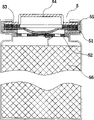
Fig. 6 is the partial enlarged drawing of Fig. 2.
Specific embodiment:
See Fig. 2,3,4,5, the utility model comprises: tank body 1, the protection block 2 that is installed on tank body 1 upper end open and the battery 3 that is positioned at tank body 1.
Protection block 2 comprises: top cover 21, explosion-proof valve 22, power-off protection apparatus 23 and becket 24.The top cover 21 that wherein adopts metal material to make is positioned at the top, explosion-proof valve 22 be positioned at top cover 21 below, below explosion-proof valve 22, be connected with power-off protection apparatus 23.Form a lug boss downwards in the middle of the explosion-proof valve 22, form the indentation 220 of ring-type in the lug boss periphery.Power-off protection apparatus 23 is welded on the lug boss of explosion-proof valve 22, the positive pole ear 31 of battery 3 and power-off protection apparatus 23 welding.
Top cover 21, explosion-proof valve 22 and becket 24 are fixing as a whole by the insulator 20 of injection mo(u)lding, during making, top cover 21, explosion-proof valve 22 and becket 24 are placed in the injection mold cavity, inwardly inject plastic material then, be shaped to insulator 20, this insulator 20 also fixedly becomes an indivisible integral body with top cover 21, explosion-proof valve 22 and becket 24 in moulding.
The external diameter of becket 24 is identical with the aperture of tank body 1 upper end open.This becket 24 is used for and tank body 1 welding, and it is positioned at the periphery of insulator 20, and its edge and the weldering of tank body 1 upper end open are fixedly connected on protection block 2 on the tank body 1 to connect.The external diameter that is positioned at the insulator bottom 201 of becket 24 lower surfaces is slightly less than the external diameter of becket 24, and promptly insulator bottom 201 outer rims and becket 24 form and tank body 1 upper end open engagement tread.Difference between normal conditions lower insulator bottom 201 outer radius and becket 24 outer radius is suitable with the wall thickness of tank body 1.When mounted, insulator bottom 201 just in time can fall in the tank body 1, becket 24 just in time is sealed on tank body 1 upper end open place simultaneously, and weld together the encapsulation of just having finished battery protection block 2 by laser welding with both this moment, and the entire job process is very simple.
In order to ensure firm connection the between top cover 21, explosion-proof valve 22 and becket 24 and the insulator 20, the outer rim that coats at explosion-proof valve 22 insulated bodys 20 forms a bending holder 221, and the outer rim of top cover 21 is by above-mentioned bending holder 221 clampings.The inner edge that described becket 24 insulated bodys 20 coat forms a kink 241.Adopt said structure can make combine between insulator 20 and top cover 21, explosion-proof valve 22 and the becket 24 more firm, be difficult to separation, come off.
See Fig. 2,6, tank body 1 comprises: the main body of the no end 11 of tubular and the chassis 12 that is welded on main body 11 bottom surface ports.Chassis 12 adopts stainless steels to make, and it is slightly thicker than no end main body 11, and the employing laser welding is fixed together between chassis 12 and the main body 11.Chassis 12 is provided with steam vent 4.During fabrication, this steam vent 4 is a non-through hole that is opened on the chassis 12, thereby promptly steam vent 4 need be under the foreign object effect be broken it and formed through hole.Usually, this steam vent 4 be used to discharge battery change into adopt a plastic film to be affixed on the steam vent inboard before producing gas to seal.Main body 11 and chassis 12 adopts stainless steel materials to make, and is convenient to process steam vent 4 like this and stopple 41 is installed in the steam vent 4.In addition, adopt stainless steel material need not carry out electroplating processes.
When the utility model is installed, at first, the negative lug of battery 3 is welded on the chassis 12, then battery 3 is put into tank body 1, simultaneously chassis 12 is installed in main body 11 bottom ports, and both are welded together.Then; according to making protection block 2 noted earlier; battery 3 positive pole ears 31 are welded together with the power-off protection apparatus 23 that protect in the block 2; the protection block 2 good with battery 3 welding is installed in tank body 1 upper port, 2 combines with the main body 11 of tank body 1 through protect behind the solder up to block a shot.Inject electrolyte at last.With plastic film entire cell is encapsulated after injecting electrolyte, next successively battery is changed into processing.This moment, tank body 1 was air-tight state because steam vent 4 is not run through.After changing into processing, need to discharge gas in the battery, break steam vent 4 with foreign object, allow tank body 1 inner space and external communications, the gas of battery in formation process is discharged, then a stopple 41 is pressed into steam vent 4 and it is welded on steam vent 4 places, form the battery that assembles this moment.
Stopple 41 can be selected a steel ball, and steel ball firmly is pressed in the steam vent 4, by welding manner steel ball is fixed in the steam vent 4 then, with in steam vent 4 shutoff.Steam vent 4 just can not have a negative impact to the follow-up use of battery like this.
During use, if when battery 3 causes internal gas pressure to increase to the protection pressure of setting because of inefficacy, for example battery 3 air pressure inside raise fast.The utility model can guarantee cell safeties by protection block 2, and promptly air pressure is when reach set point, and protection block 2 interior explosion-proof valves 22 pop and pressure release, avoids the battery accident of blasting.
In order further to improve fail safe of the present utility model, between top cover 21 and explosion-proof valve 22, a positive temperature coefficient ring plate can be set in the protection block 2.This positive temperature coefficient ring plate is got up by solid envelope equally, forms an integral body with insulator 20.During use, if when battery 3 external short circuits or charging and discharging currents surpass the operating current of positive temperature coefficient ring plate, the positive temperature coefficient ring plate raises by temperature, and resistance increases and reduces electric current, with the protection battery.
Certainly; the above only is an example of the present utility model; be not to limit practical range of the present utility model, all equivalences of doing according to the described structure of the utility model claim, feature and principle change or modify, and all should be included in the protection range of the application's patent.