EP3477588A1 - Image processing apparatus, image processing method, and recording medium - Google Patents
Image processing apparatus, image processing method, and recording medium Download PDFInfo
- Publication number
- EP3477588A1 EP3477588A1 EP18193424.1A EP18193424A EP3477588A1 EP 3477588 A1 EP3477588 A1 EP 3477588A1 EP 18193424 A EP18193424 A EP 18193424A EP 3477588 A1 EP3477588 A1 EP 3477588A1
- Authority
- EP
- European Patent Office
- Prior art keywords
- break
- coating material
- image processing
- coating
- processing apparatus
- Prior art date
- Legal status (The legal status is an assumption and is not a legal conclusion. Google has not performed a legal analysis and makes no representation as to the accuracy of the status listed.)
- Granted
Links
Images






Classifications
-
- G—PHYSICS
- G06—COMPUTING OR CALCULATING; COUNTING
- G06T—IMAGE DATA PROCESSING OR GENERATION, IN GENERAL
- G06T7/00—Image analysis
- G06T7/0002—Inspection of images, e.g. flaw detection
- G06T7/0004—Industrial image inspection
- G06T7/0008—Industrial image inspection checking presence/absence
-
- G—PHYSICS
- G01—MEASURING; TESTING
- G01N—INVESTIGATING OR ANALYSING MATERIALS BY DETERMINING THEIR CHEMICAL OR PHYSICAL PROPERTIES
- G01N21/00—Investigating or analysing materials by the use of optical means, i.e. using sub-millimetre waves, infrared, visible or ultraviolet light
- G01N21/84—Systems specially adapted for particular applications
- G01N21/88—Investigating the presence of flaws or contamination
- G01N21/8851—Scan or image signal processing specially adapted therefor, e.g. for scan signal adjustment, for detecting different kinds of defects, for compensating for structures, markings, edges
-
- G—PHYSICS
- G01—MEASURING; TESTING
- G01B—MEASURING LENGTH, THICKNESS OR SIMILAR LINEAR DIMENSIONS; MEASURING ANGLES; MEASURING AREAS; MEASURING IRREGULARITIES OF SURFACES OR CONTOURS
- G01B11/00—Measuring arrangements characterised by the use of optical techniques
- G01B11/02—Measuring arrangements characterised by the use of optical techniques for measuring length, width or thickness
- G01B11/04—Measuring arrangements characterised by the use of optical techniques for measuring length, width or thickness specially adapted for measuring length or width of objects while moving
- G01B11/046—Measuring arrangements characterised by the use of optical techniques for measuring length, width or thickness specially adapted for measuring length or width of objects while moving for measuring width
-
- G—PHYSICS
- G05—CONTROLLING; REGULATING
- G05B—CONTROL OR REGULATING SYSTEMS IN GENERAL; FUNCTIONAL ELEMENTS OF SUCH SYSTEMS; MONITORING OR TESTING ARRANGEMENTS FOR SUCH SYSTEMS OR ELEMENTS
- G05B19/00—Program-control systems
- G05B19/02—Program-control systems electric
- G05B19/418—Total factory control, i.e. centrally controlling a plurality of machines, e.g. direct or distributed numerical control [DNC], flexible manufacturing systems [FMS], integrated manufacturing systems [IMS] or computer integrated manufacturing [CIM]
- G05B19/4183—Total factory control, i.e. centrally controlling a plurality of machines, e.g. direct or distributed numerical control [DNC], flexible manufacturing systems [FMS], integrated manufacturing systems [IMS] or computer integrated manufacturing [CIM] characterised by data acquisition, e.g. workpiece identification
-
- G—PHYSICS
- G06—COMPUTING OR CALCULATING; COUNTING
- G06T—IMAGE DATA PROCESSING OR GENERATION, IN GENERAL
- G06T7/00—Image analysis
- G06T7/0002—Inspection of images, e.g. flaw detection
- G06T7/0004—Industrial image inspection
- G06T7/001—Industrial image inspection using an image reference approach
-
- G—PHYSICS
- G06—COMPUTING OR CALCULATING; COUNTING
- G06T—IMAGE DATA PROCESSING OR GENERATION, IN GENERAL
- G06T7/00—Image analysis
- G06T7/10—Segmentation; Edge detection
-
- G—PHYSICS
- G06—COMPUTING OR CALCULATING; COUNTING
- G06T—IMAGE DATA PROCESSING OR GENERATION, IN GENERAL
- G06T7/00—Image analysis
- G06T7/10—Segmentation; Edge detection
- G06T7/13—Edge detection
-
- G—PHYSICS
- G01—MEASURING; TESTING
- G01N—INVESTIGATING OR ANALYSING MATERIALS BY DETERMINING THEIR CHEMICAL OR PHYSICAL PROPERTIES
- G01N21/00—Investigating or analysing materials by the use of optical means, i.e. using sub-millimetre waves, infrared, visible or ultraviolet light
- G01N21/84—Systems specially adapted for particular applications
- G01N21/88—Investigating the presence of flaws or contamination
- G01N21/8851—Scan or image signal processing specially adapted therefor, e.g. for scan signal adjustment, for detecting different kinds of defects, for compensating for structures, markings, edges
- G01N2021/8854—Grading and classifying of flaws
- G01N2021/8861—Determining coordinates of flaws
- G01N2021/8864—Mapping zones of defects
-
- G—PHYSICS
- G01—MEASURING; TESTING
- G01N—INVESTIGATING OR ANALYSING MATERIALS BY DETERMINING THEIR CHEMICAL OR PHYSICAL PROPERTIES
- G01N21/00—Investigating or analysing materials by the use of optical means, i.e. using sub-millimetre waves, infrared, visible or ultraviolet light
- G01N21/84—Systems specially adapted for particular applications
- G01N21/88—Investigating the presence of flaws or contamination
- G01N21/8851—Scan or image signal processing specially adapted therefor, e.g. for scan signal adjustment, for detecting different kinds of defects, for compensating for structures, markings, edges
- G01N2021/8887—Scan or image signal processing specially adapted therefor, e.g. for scan signal adjustment, for detecting different kinds of defects, for compensating for structures, markings, edges based on image processing techniques
-
- G—PHYSICS
- G05—CONTROLLING; REGULATING
- G05B—CONTROL OR REGULATING SYSTEMS IN GENERAL; FUNCTIONAL ELEMENTS OF SUCH SYSTEMS; MONITORING OR TESTING ARRANGEMENTS FOR SUCH SYSTEMS OR ELEMENTS
- G05B19/00—Program-control systems
- G05B19/02—Program-control systems electric
- G05B19/04—Program control other than numerical control, i.e. in sequence controllers or logic controllers
- G05B19/05—Programmable logic controllers, e.g. simulating logic interconnections of signals according to ladder diagrams or function charts
-
- G—PHYSICS
- G06—COMPUTING OR CALCULATING; COUNTING
- G06T—IMAGE DATA PROCESSING OR GENERATION, IN GENERAL
- G06T2207/00—Indexing scheme for image analysis or image enhancement
- G06T2207/30—Subject of image; Context of image processing
- G06T2207/30172—Centreline of tubular or elongated structure
Definitions
- the present invention relates to a technology for detecting a break in a coating material with which an inspection object is coated.
- FA factory automation
- technologies for automatically inspecting an inspection object such as a workpiece are widely used.
- a coating material such as a sealing material as is intended. Through the inspection, whether or not a sealing material is broken, whether or not a width of a sealing material is appropriate, whether or not intended places are coated with the sealing material, and the like are detected.
- Patent Document 1 discloses an inspection device "capable of performing an inspection on a coating state of a sealing material using image processing with high efficiency".
- the inspection device receives settings of first and second points for an image representing the sealing material. Thereafter, the inspection device determines the presence/absence of a break in the sealing material based on whether or not the second point can be reached by tracking the sealing material from the first point.
- Patent Document 2 discloses an inspection device "capable of determining the appropriateness/inappropriateness of a path of a linear pattern using a simple method with a high accuracy and reliably detecting a defect when there is a defect such as a break, a bonding defect, or the like.”
- the inspection device receives settings of first and second virtual lines such that the virtual lines traverse a coating material in an image. Thereafter, the inspection device performs outline tracking from edge points on the first virtual line and determines the presence/absence of a break in the sealing material based on whether the first virtual line or the second virtual line can be reached as results of tracking.
- Patent Document 3 discloses a sealing inspection system for "inspecting a coating state of a sealing material using a state in an image.”
- the sealing inspection system two edge points are retrieved from inspection points set in advance in a coating material in an image and a distance between the two edge points is detected as a width of the sealing material.
- the inspection device disclosed in Patent Document 1 tracks a sealing material from the first point set in advance and determines whether or not a sealing material is broken on the basis whether or not the second point can be reached by tracking the sealing material from the first point set in advance. For this reason, while the inspection device can detect whether or not a sealing material is divided, it cannot detect how the sealing material is broken. For example, when a coating material is divided into three or more parts, the inspection device cannot detect that the coating material is divided into three or more parts.
- the inspection device disclosed in Patent Document 2 performs outline tracking from edge points on a first virtual line set in advance and determines the presence/absence of a break in a sealing material based on whether or not the first virtual line or the second virtual line can be arrived at as results of tracking. For this reason, while the inspection device can detect whether or not a sealing material is divided, it cannot detect how the sealing material is broken. For example, when a coating material is divided into three or more parts, the inspection device cannot detect that the coating material is divided into three or more parts.
- the sealing inspection system disclosed in Patent Document 3 retrieves two edge points from inspection points set in advance and detects a distance between the two edge points as a width of the sealing material.
- the sealing inspection system can detect that a sealing material is divided into a plurality of parts based on a width of the coating material detected for each inspection point.
- the sealing inspection system retrieves two edge points for each inspection point and accordingly, cannot detect an inclined break representing that a linearly-coated sealing material is diagonally broken with respect to the direction of a line.
- an objective of the disclosure according to an aspect is to provide a technology capable of detecting both a break in a plurality of parts in a coating material and an inclined break of a coating material.
- an image processing apparatus includes a grouping unit that is used for extracting coating areas representing a coating material from an input image acquired by imaging an inspection object linearly coated with the coating material and grouping the coating areas for each sequence of linear parts, a calculation unit that is used for calculating a line width in an orthogonal direction of a linear part for each of the linear parts in a plurality of portions of the coating area including end portions of the linear parts, a break detecting unit that is used for detecting a break in the coating material based on the line widths calculated in the plurality of portions, and an output unit that is used for outputting an indication representing occurrence of a break when the break is detected.
- the image processing apparatus can detect both a plurality of breaks in a coating material and an inclined break of the coating material.
- the output unit displays the input image and displays a portion in which the break has occurred on the input image in an emphasized manner compared with other portions.
- a user can perceive a portion in which a break has occurred at a glance.
- the emphasized displaying includes displaying a straight line along the break.
- a user can easily perceive a direction in which a break has occurred.
- the output unit further displays the number of groups into which the coating area is grouped by the grouping unit as the number of breaks of the coating material.
- the user can easily perceive the number of breaks of the coating material.
- the calculation unit sets straight lines in a plurality of portions of a predetermined reference path such that the straight lines are orthogonal to the reference path representing positions at which the coating material is to be shown in an image and detects two edge points presented on each of the set straight lines for each of the linear parts and calculates a distance between the two edge points as the line width.
- an edge point is necessarily presented on a straight line set to be orthogonal to the coating area representing the coating material, and accordingly, the image processing apparatus can accurately calculate the line width.
- the break detecting unit detects the break.
- line widths are calculated at a plurality of portions of the coating area for each sequence of linear parts that are grouped, and accordingly, the image processing apparatus can easily detect an inclined break of the coating material.
- an image processing method includes extracting coating areas representing a coating material from an input image acquired by imaging an inspection object linearly coated with the coating material and grouping the coating areas for each sequence of linear parts, calculating a line width in an orthogonal direction of the linear part for each of the linear parts in a plurality of portions of the coating area including end portions of the linear parts, detecting a break in the coating material based on the line widths calculated in the plurality of portions, and outputting an indication representing occurrence of the break when the break is detected.
- the image processing method can detect both a plurality of breaks in a coating material and an inclined break of the coating material.
- a non-transitory computer readable recording medium recording an image processing program causes the computer to execute: extracting coating areas representing a coating material from an input image acquired by imaging an inspection object linearly coated with the coating material and grouping the coating areas for each sequence of linear parts, calculating a line width in an orthogonal direction of the linear part for each of the linear parts in a plurality of portions of the coating area including end portions of the linear parts, detecting a break in the coating material based on the line widths calculated in the plurality of portions, and outputting an indication representing occurrence of the break when the break is detected.
- the image processing program can detect both a plurality of breaks in a coating material and an inclined break of the coating material.
- both a break in a plurality of parts in a coating material and an inclined break of a coating material can be detected.
- FIG. 1 is a conceptual diagram schematically illustrating an image processing system 1 according to this embodiment.
- the image processing system 1 is, for example, configured of an imaging unit 8 used for imaging an inspection object and an image processing apparatus 100 used for executing predetermined image processing for an image acquired from the imaging unit 8.
- the imaging unit 8 may be configured as being separated from the image processing apparatus 100 or may be configured integrally with the image processing apparatus 100.
- the image processing apparatus 100 includes a control device 110 used for controlling the image processing apparatus 100 and an output unit 101 used for outputting results of an inspection as major components.
- the control device 110 includes a grouping unit 152, a calculation unit 154, and a break detecting unit 156 as major functional components.
- the imaging unit 8 images a workpiece W conveyed on a conveyer and generates an input image representing the workpiece W.
- the workpiece W is an inspection object and is, for example, a product or a semifinished product.
- the workpiece W is coated with a coating material 7.
- the coating material 7 is, for example, an adhesive agent such as a sealing material.
- the imaging unit 8 sequentially outputs generated input images 30 to the grouping unit 152 of the control device 110.
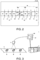
- FIG. 2 is a diagram illustrating functions of the image processing apparatus 100.
- a part of an input image 30 is illustrated as an input image 35.
- the grouping unit 152 extracts coating areas 64 representing coating material 7 from the input image 35 and groups the coating areas 64 for each sequence of linear parts.
- a linear part 64A of the coating area 64 is grouped as a group G1.
- a linear part 64B of the coating area 64 is grouped as a group G2.
- a linear part 64C of the coating area 64 is grouped as a group G3.
- Results of the grouping using the grouping unit 152 are output to the calculation unit 154.
- results of grouping include identification information used for identifying the groups G1 to G3, coordinate values of the groups G1 to G3 inside the image, and the like.
- the calculation unit 154 calculates a line width (thickness) of each of the linear parts 64A to 64C in an orthogonal direction of the linear part at a plurality of portions in the coating area 64 including end portions of the linear parts 64A to 64C.
- An end portion described here does not need to be a tip end of each of the linear parts 64A to 64C and may represent a portion within a predetermined distance (a predetermined number of pixels) from the tip end of each of the linear parts 64A to 64C. Details of a method of calculating a line width will be described later.
- the calculation unit 154 calculates line widths on reference straight lines L1 to L9. More specifically, for the linear part 64A, the calculation unit 154 calculates line widths W1 to W4 and W5A on reference straight lines L1 to L5. For the linear part 64B, the calculation unit 154 calculates line widths W5B, W6, and W7 on reference straight lines L5 to L7. For the linear part 64C, the calculation unit 154 calculates a line width W9 on a reference straight line L9. The calculated line widths W1 to W4, W5A, W5B, W6, W7, and W9 are output to the break detecting unit 156.
- the break detecting unit 156 detects a break in the coating material based on the line widths W1 to W4, W5A, W5B, W6, W7, and W9 calculated for the linear parts 64A to 64C. While details will be described later, the break detecting unit 156, for example, can detect an inclined break representing that a linear coating material is broken by being inclined with respect to a tangential direction of the coating material based on calculation of a plurality of line widths for one of the reference straight lines L1 to L9. In the example illustrated in FIG. 2 , since a plurality of line widths W5A and W5B are detected for one reference straight line L5, the break detecting unit 156 detects an inclined break on the reference straight line L5.
- the output unit 101 is a unit that is used for outputting results of an inspection.
- the output unit 101 may be a display unit 102 (see FIG. 3 ) to be described later, a speaker that outputs sound, an indicator, or any other output device.
- the output unit 101 outputs an indication representing an occurrence of a break. In the example illustrated in FIG. 1 , a circle 38 is attached to a place at which a break has occurred.
- the image processing apparatus 100 can detect a break in the coating material.
- FIG. 3 is a diagram illustrating one example of the entire configuration of the image processing system 1.
- the image processing system 1 includes an image processing apparatus 100 that is also referred to as a visual sensor, a programmable logic controller (PLC) 5 that can communicate with the image processing apparatus 100, and an imaging unit 8 (an image acquiring unit) that is connected to the image processing apparatus 100 as major components.
- PLC programmable logic controller
- the PLC 5 executes control of a conveying mechanism 6 such as a conveyer by cooperating with the image processing apparatus 100.
- the imaging unit 8 is configured to include imaging devices, which are partitioned into a plurality of pixels, such as coupled charged devices (CCD) or complementary metal oxide semiconductor (CMOS) sensors.
- CCD coupled charged devices
- CMOS complementary metal oxide semiconductor
- the imaging unit 8 sequentially images workpieces W conveyed by the conveying mechanism 6. Input images acquired through imaging using the imaging unit 8 are transmitted to the image processing apparatus 100.
- the image processing apparatus 100 inspects whether or not an inspection object is coated with a coating material as is intended. For example, the image processing apparatus 100 may inspect whether or not a coating material is broken, whether or not a coating width of a coating material is appropriate, whether or not an intended place is coated with a coating material, and the like. Results of the inspection performed by the image processing apparatus 100 are displayed on the display unit 102.
- FIG. 4 is a schematic diagram illustrating one example of the hardware configuration of the image processing apparatus 100.
- the image processing apparatus 100 typically, has a structure according to a general-purpose computer architecture, and, by executing a program installed in advance using a processor, various image processes described with reference to FIG. 1 are realized.
- the image processing apparatus 100 includes a control device 110 such as a central processing unit (CPU) or a micro-processing unit (MPU), a random access memory (RAM) 112, a display controller 114, a system controller 116, an input/output (I/O) controller 118, a storage device 120, a camera interface 122, an input interface 124, a PLC interface 126, a communication interface 128, and a memory card interface 130.
- a control device 110 such as a central processing unit (CPU) or a micro-processing unit (MPU), a random access memory (RAM) 112, a display controller 114, a system controller 116, an input/output (I/O) controller 118, a storage device 120, a camera interface 122, an input interface 124, a PLC interface 126, a communication interface 128, and a memory card interface 130.
- CPU central processing unit
- MPU micro-processing unit
- RAM random access memory
- I/O controller 118 input/out
- the control device 110 exchanges a program (code) and the like with the system controller 116 and executes them in a predetermined order, thereby realizing a target arithmetic operation process.
- the system controller 116 is connected to the control device 110, the RAM 112, the display controller 114, and the I/O controller 118 through a bus, performs exchange of data and the like with each unit, and is responsible for the overall process of the image processing apparatus 100.
- the RAM 112 is, typically a volatile memory such as a dynamic random access memory (DRAM) and stores a program read from the storage device 120, an input image acquired by the imaging unit 8, results of the processing for the input image, workpiece data, and the like.
- DRAM dynamic random access memory
- the display controller 114 is connected to the display unit 102 and outputs a signal for displaying various kinds of information to the display unit 102 in accordance with an internal command supplied from the system controller 116.
- the display unit 102 for example, includes a liquid crystal display, an organic electro luminescence (EL) display, an organic EL, or the like.
- the display unit 102 as illustrated in FIG. 4 , may be integrally configured with the image processing apparatus 100 or may be configured separately from the image processing apparatus 100.
- the I/O controller 118 controls data exchange with a recording medium or an external device connected to the image processing apparatus 100. More specifically, the I/O controller 118 is connected to the storage device 120, the camera interface 122, the input interface 124, the PLC interface 126, the communication interface 128, and the memory card interface 130.
- the storage device 120 is, typically, a nonvolatile magnetic storage device, and various setting values and the like are stored therein in addition to an image processing program 20 executed by the control device 110. In addition, an input image acquired from the imaging unit 8 is stored in the storage device 120.
- a semiconductor memory device such as a flash memory or an optical memory device such as a digital versatile disk random access memory (DVD-RAM) may be employed.
- DVD-RAM digital versatile disk random access memory
- the camera interface 122 corresponds to an input unit that receives image data generated by imaging a workpiece W (inspection object) and relays data transmission between the control device 110 and the imaging unit 8. More specifically, the camera interface 122 can be connected to one or more imaging units 8, an imaging instruction being output from the control device 110 to the imaging units 8 through the camera interface 122. Accordingly, the imaging unit 8 images a subject and outputs a generated image to the control device 110 through the camera interface 122.
- the input interface 124 relays data transmission between the control device 110 and input devices such as a keyboard 104, a mouse, a touch panel, and a dedicated console. In other words, the input interface 124 accepts an operation instruction given by a user operating an input device.
- the PLC interface 126 relays data transmission between the PLC 5 and the control device 110. More specifically, the PLC interface 126 transmits information relating to the state of a production line, information relating to a workpiece W, and the like controlled by the PLC 5 to the control device 110.
- the communication interface 128 relays data transmission between the control device 110 and another personal computer, a server apparatus, or the like not illustrated in the drawings.
- the communication interface 128 is, typically, configured using Ethernet (registered trademark), a universal serial bus (USB), or the like.
- Ethernet registered trademark
- USB universal serial bus
- a program downloaded into a transfer server or the like through the communication interface 128 may be installed in the image processing apparatus 100.
- the communication interface 128 may receive a signal indicating the state of the imaging unit 8 from the imaging unit 8, the PLC 5, or the like.
- the signal indicates whether or not the imaging unit 8 is performing imaging.
- the memory card interface 130 relays data transmission between the control device 110 and the memory card 106 serving as a recording medium.
- an image processing program 20 and the like executed by the image processing apparatus 100 is distributed and stored, and the memory card interface 130 reads the image processing program 20 from the memory card 106.
- the memory card interface 130 writes a camera image acquired by the imaging unit 8 and/or results of the process performed by the image processing apparatus 100, and the like in the memory card 106.
- the memory card 106 is configured using a general semiconductor memory device such as a secure digital (SD) card, a magnetic recording medium such as a flexible disk, an optical recording medium such as a compact disk read only memory (CD-ROM), or the like.
- SD secure digital
- CD-ROM compact disk read only memory
- an operating system (OS) used for providing basic functions of the computer may be installed.
- the image processing program according to this embodiment may execute a process of calling necessary modules in a predetermined order and/or at a predetermined timing among programs modules provided as a part of the OS.
- the program according to this embodiment may not include the modules as described above, and there are also cases in which processes are executed by cooperation with the OS. Accordingly, the image processing program according to this embodiment may have a form not including some of such modules.
- the image processing program according to this embodiment may be embedded into a part of another program. Also in such a case, the program does not need to include modules included in the other program in which the program is embedded, and the process may be executed by cooperation with the other program. In other words, the image processing program according to this embodiment may have a form of being embedded into such another program.
- some or all of the functions provided by executing the image processing program may be embedded as a dedicated hardware circuit.
- the inspection flow using the image processing apparatus 100 can be roughly divided into a setting process and an inspection process.
- the setting process is a process executed before the inspection process and is performing setting of parameters of various kinds of image processing executed in the inspection process.
- the image processing apparatus 100 executes an inspection process for the coating quality of a coating material in accordance with various parameters set in the setting process.
- the setting process and the inspection process are realized by the control device 110 of the image processing apparatus 100 executing a program.
- a part or the whole of the process may be executed by circuit elements or any other hardware.
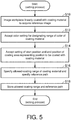
- FIG. 5 is a flowchart illustrating the setting process executed by the control device 110.
- Step S10 the control device 110 outputs an imaging instruction to the imaging unit 8 and causes the imaging unit 8 to image a workpiece linearly coated with a coating material. Accordingly, the control device 110 acquires a reference image representing a workpiece coated with a coating material.
- the reference image acquired in Step S10 is acquired by imaging a workpiece that is normally coated with a coating material and is an image that becomes a model of the coating quality of a coating material.
- Step S12 the control device 110 accepts color settings used for designating the range of colors of the coating material.
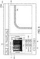
- FIG. 6 is a diagram illustrating one example of a setting screen 10 displayed in Step S12.
- the setting screen 10 includes a tab TB used for displaying various setting screens.
- a color setting screen 10A used for designating the range of colors of the coating material is displayed.
- the color setting screen 10A includes a color setting area 31, an image display area 32A, an OK button 46, and a cancel button 48.
- the color setting area 31 a user can input a setting of a hue range of the coating material, a setting of a saturation range of the coating material, and a setting of a lightness range of the coating material.
- the hue range, the saturation range, and the lightness range will be collectively referred to as a "color range.”
- the color setting area 31 includes a pointer designation area 31A in which a setting of the color range of the coating material is accepted through pointer designation and a numerical value input area 31B in which a setting of the color range of the coating material is accepted through a numeral value input.
- the setting of the hue range of the coating material is set using a pointer H1 used for setting a lower limit value of the hue and a pointer H2 used for setting an upper limit value of the hue.
- the pointers H1 and H2 are configured to be slidable in the horizontal direction on the sheet face using a mouse operation or a touch operation.
- a range designated by the pointers H1 and H2 is set as the hue range of the coating material.
- the setting of the saturation range of the coating material is set using a pointer C1 used for setting a lower limit value of the saturation and a pointer C2 used for setting an upper limit value of the saturation.
- the pointers C1 and C2 are configured to be slidable in the vertical direction on the sheet face using a mouse operation or a touch operation.
- a range designated by the pointers C1 and C2 is set as the saturation range of the coating material.
- the setting of the lightness range of the coating material is set using a pointer B1 used for setting a lower limit value of the lightness and a pointer B2 used for setting an upper limit value of the lightness.
- the pointers B1 and B2 are configured to be slidable in the vertical direction on the sheet face using a mouse operation or a touch operation.
- a range designated by the pointers B1 and B2 is set as the lightness range of the coating material.
- a user in the numerical value input area 31B, can input the lower limit value of the hue, the upper limit value of the hue, the lower limit value of the saturation, the upper limit value of the saturation, the lower limit value of the lightness, and the upper limit value of the lightness as numerical values.
- positions of the pointers in the pointer designation area 31A and numerical values in the numerical value input area 31B are linked with each other.
- the control device 110 binarizes the reference image in accordance with the color range designated in the color setting area 31. For example, when each pixel of the reference image is included in the color range designated in the color setting area 31, the control device 110 sets the value of these pixels as "1.” On the other hand, when each pixel of the reference image is not included in the color range designated in the color setting area 31, the control device 110 sets the value of these pixels as "0.” Accordingly, the control device 110 generates a binarized image from the reference image. The binarized image is displayed in the image display area 32A. Preferably, the control device 110 links the display of a binarized image displayed in the image display area 32A with the setting for the color setting area 31. A user can easily perform setting of the color range of a coating material by performing setting for the color setting area 31 while checking the binarized image.
- the control device 110 stores the setting of the color range set in the color setting area 31 in the storage device 120 (see FIG. 4 ).
- the control device 110 closes the display of the color setting screen 10A without storing the setting of the color range set in the color setting area 31.
- Step S14 the control device 110 accepts a setting of a start position and an end position of a range to be coated with a coating material.
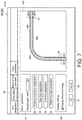
- FIG. 7 is a diagram illustrating one example of the setting screen 10 displayed in Step S14.
- an area setting screen 10B for designating a range to be coated with a coating material is displayed.
- the area setting screen 10B includes a width designation area 51, a measurement area registration button 52, a start line registration button 53, an end line registration button 54, a reference path generation button 55, a check box 56, an OK button 57, and a cancel button 58.
- the control device 110 performs sequential switching of a display of the reference image and the binarized image in accordance with an operation for the check box 56. More specifically, when "check” is not inserted into the check box 56, the control device 110 displays the reference image in the image display area 32A. On the other hand, when "check" is inserted into the check box 56, the control device 110 displays the binarized image in the image display area 32A.
- a user can set an allowed width of a path to be coated with the coating material in units of pixels.
- "NG" is acquired as results of the inspection.
- the measurement area registration button 52 accepts registration of an image area to be inspected. More specifically, a user performs area designation for an image displayed in the image display area 32A. For example, the designation of the area is realized through a mouse operation, a touch operation, or the like.
- the control device 110 stores the designated inspection object area in the storage device 120 (see FIG. 4 ). Accordingly, an image area to be inspected and an image area not to be inspected are distinguished from each other.
- the start line registration button 53 accepts registration of a start position of a range to be coated with a coating material. More specifically, a user can designate a start position of a coating area 36A for an image displayed in the image display area 32A. In the example illustrated in FIG. 7 , a start line ST is set as the start position.
- the setting of the start line ST is, for example, realized through a mouse operation, a touch operation, or the like.
- the start line ST is set such that it traverses the coating area 36A.
- the control device 110 stores the position (coordinate values) of the start line ST inside the image in the storage device 120 (see FIG. 4 ).
- the end line registration button 54 accepts registration of an end position of a range to be coated with the coating material. More specifically, a user can designate an end position of the coating area 36A for the image displayed in the image display area 32A. In the example illustrated in FIG. 7 , an end line ED is set as the end position.
- the setting of the end line ED is, for example, realized through a mouse operation, a touch operation, or the like.
- the end line ED is set such that it traverses the coating area 36A.
- the control device 110 stores the position (coordinate values) of the end line ED inside the image in the storage device 120 (see FIG. 4 ).
- the reference path generation button 55 is a button used for executing a process of automatically calculating a range to be coated with a coating material.
- the control device 110 executes the process of Step S16 illustrated in FIG. 5 based on reception of pressing of the reference path generation button 55.
- Step S16 the control device 110 applies a differential filter for a binarized image acquired from the reference image based on the color range set in Step S12 described above, thereby generating a differential image representing an edge portion (gradient).
- a pixel value of an edge portion is represented as "1,” and a pixel value of a non-edge portion is represented as "0.”
- the control device 110 detects two edge points (in other words, start points SP1 and SP2) of which pixel values are "1" on the start line ST and detects two edge points (end points EP1 and EP2) of which pixel values are "1" on the end line ED.
- the control device 110 searches for an edge point for pixels adjacent to the start point SP1 on the differential image in the counterclockwise direction. When an edge point is retrieved, the control device 110 stores coordinate values of the edge point and sets the edge point as a target pixel. Thereafter, the control device 110 searches for an edge point for pixels adjacent to the target pixel on the differential image in the counterclockwise direction. By repeating such a process, the control device 110 detects a group of coordinate values of edge points from the start point SP1 to the end point EP1 as an outline 38A. Similarly, the control device 110 detects a group of coordinate values of edge points from the start point SP2 to the end point EP2 as an outline 38B.
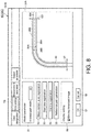
- FIG. 8 is a diagram illustrating one example of the setting screen 10 displayed after the reference path generation button 55 is pressed.
- the control device 110 specifies allowed coating ranges 39A and 39B that are allowed as coating positions of the coating material based on the outlines 38A and 38B.
- the control device 110 extends ranges surrounded by the outlines 38A and 38B to the outer side by a width set in the width designation area 51 and specifies the ranges after the extension as allowed coating ranges 39A and 39B.
- control device 110 specifies a center line of the outlines 38A and 38B as a reference path 40 representing positions to be coated with the coating material. More specifically, the control device 110 specifies a corresponding point on the outline 38B for each point on the outline 38A. For example, the control device 110 specifies points on the outline 38B having shortest distances from points on the outline 38A as corresponding points. The control device 110 specifies a line connecting midpoints between the corresponding points on the outlines 38A and 38B as the reference path 40.
- Step S18 the control device 110 stores the allowed coating ranges 39A and 39B and the reference path 40 specified in Step S16 in the storage device 120 (see FIG. 4 ).
- the control device 110 closes the display of the area setting screen 10B without storing the allowed coating ranges 39A and 39B and the reference path 40.
- FIG. 9 is diagram illustrating a flowchart representing the inspection process executed by the control device 110.
- the control device 110 performs an inspection of the coating quality of a coating material in accordance with various parameters set in the setting process described above.
- Step S50 the control device 110 outputs an imaging instruction to the imaging unit 8 and causes the imaging unit 8 to image a workpiece linearly coated with a coating material. Accordingly, the control device 110 acquires an input image representing the workpiece coated with the coating material.
- FIG. 10 is a diagram illustrating an input image 62 acquired from the imaging unit 8.
- the input image 62 includes a workpiece area 63 representing a workpiece and a coating area 64 representing a coating material.
- the coating area 64 is divided into linear parts 64A to 64C.
- the control device 110 extracts the coating area 64 from the input image 62. More specifically, the control device 110 binarizes the input image in accordance with the color range of the coating material set in the setting process described above. For example, when each pixel of the input image is included in the set color range, the control device 110 sets the value of the pixel as "1.” On the other hand, when each pixel of the input image is not included in the set color range, the control device 110 sets the value of the pixel as "0.” In other words, pixels of which pixel values are "1" are extracted as a coating area representing the coating material.
- FIG. 11 is a diagram illustrating the binarized image 65 acquired from the input image 62. As illustrated in FIG. 11 , in the binarized image 65, only the coating area 64 is extracted.
- Step S54 the control device 110 serving as the grouping unit 152 (see FIG. 1 ) described above groups the coating area 64 for each sequence of linear parts.
- the control device 110 applies a differential filter to the binarized image 65, thereby generating a differential image representing an edge portion (gradient).
- a pixel value of an edge portion is represented as "1," and a pixel value of a non-edge portion is represented as "0.”
- the control device 110 performs raster scanning of the differential image and searches for a pixels of which a pixel value is "1.”
- the control device 110 sets the pixel as a start point.
- the control device 110 searches for edge points in the vicinity of the start point in the counterclockwise direction. When an edge point is retrieved, the control device 110 stores coordinate values of the edge point and sets the edge point as a target pixel. Thereafter, the control device 110 searches for an edge point for pixels adjacent to the target pixel on the differential image in the counterclockwise direction. The control device 110 executes such an outline tracking process until the target point is returned to the start point. The control device 110 detects a group of coordinate values stored in the process of outline tracking as an outline and specifies an area surrounded by the outline as one group.
- the control device 110 regards the group as noise.
- the control device 110 regards the group as noise.
- the control device 110 regards the group as a linear part.
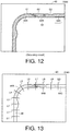
- FIG. 12 is a diagram illustrating one example of results of grouping for the binarized image 65.
- a linear part 64A of the coating area 64 is grouped as a group G1
- a linear part 64B of the coating area 64 is grouped as a group G2
- a linear part 64C of the coating area 64 is grouped as a group G3.
- Step S56 the control device 110 serving as the calculation unit 154 (see FIG. 1 ) described above sets a reference straight line such that it is orthogonal to the tangential direction of the reference path 40 in a plurality of places on the reference path 40 (see FIG. 8 ) set in the setting process described above.
- FIG. 13 is a diagram illustrating one example of a reference straight line set for the coating area 64. In the example illustrated in FIG. 13 , reference straight lines L1 to L9 are set.
- Step S58 for each of the linear parts 64A to 64C, the control device 110 serving as the calculation unit 154 (see FIG. 1 ) described above detects two edge points present on each of the reference straight lines L1 to L9 and calculates a distance between the two edge points as a line width. More specifically, the control device 110 applies a differential filter to the binarized image 65, thereby generating a differential image representing an edge portion (gradient).
- a pixel value of an edge portion is represented as "1," and a pixel value of a non-edge portion is represented as "0.”
- the control device 110 scans the reference straight lines L1 to L9 on the differential image and searches for at least two edge points of which pixel values are "1.”
- the control device 110 calculates a distance between the two edge points as a line width.
- the control device 110 calculates a distance between two edge points present on the outermost side as a line width.
- FIG. 14 is a diagram illustrating a line width calculating process for a linear part 64A.
- a binarized image 65A representing the linear part 64A is illustrated.
- the control device 110 calculates a line width at places at which the linear part 64A and the reference straight lines L1 to L7 overlap each other.
- the control device 110 detects edge points E1A and E1B on the reference straight line L1 and calculates a distance between the edge points E1A and E1B as a line width W1.
- a line width W2 is calculated for the reference straight line L2.
- a line width W3 is calculated for the reference straight line L3.
- a line width W4 is calculated for the reference straight line L4.
- a line width W5 is calculated for the reference straight line L5.
- a line width W6 is calculated for the reference straight line L6.
- a line width W7A is calculated for the reference straight line L7.
- FIG. 15 is a diagram illustrating a line width calculating process for a linear part 64B.
- a binarized image 65B representing the linear part 64B is illustrated.
- the control device 110 calculates a line width at places at which the linear part 64B and the reference straight lines L7 and L8 overlap each other.
- a line width W7B is calculated for the reference straight line L7.
- a line width W8 is calculated for the reference straight line L8.
- FIG. 16 is a diagram illustrating a line width calculating process for a linear part 64C.
- a binarized image 65C representing the linear part 64C is illustrated.
- the control device 110 calculates a line width at a place at which the linear part 64C and the reference straight line L9 overlap each other.
- a line width W9 is calculated for the reference straight line L9.
- Step S60 the control device 110 serving as the break detecting unit 156 (see FIG. 1 ) described above determines whether or not a break has occurred in the coating material based on the line widths calculated on the reference straight lines L1 to L9 and results of the grouping in Step S54.
- FIG. 17 is a diagram illustrating a break detecting process. As illustrated in FIG. 17 , the control device 110 detects a break in the coating material when the number of groups acquired in Step S54 is two or more and detects an inclined break when a plurality of line widths are calculated for one of the reference straight lines L1 to L9. In the example illustrated in FIG.
- the control device 110 determines that an inclined break has occurred on the reference straight line L7. In addition, since the coating material is grouped into three groups in Step S54, the control device 110 determines that the coating material is divided into three parts.
- a method of detecting an inclined break is not limited to the method described above, and any arbitrary method may be employed.
- the control device 110 detects an inclined break when a line width calculated at an end portion of the linear parts 64A to 64C is equal to or less than a predetermined value.
- the control device 110 determines that an inclined break has occurred on the reference straight line L7.
- Step S62 the control device 110 determines whether or not a deviation has occurred in a coating position of the coating material based on the allowed coating ranges 39A and 39B (see FIG. 8 ) set in the setting process described above. More specifically, the control device 110 executes an outline tracking process starting from the start line ST set in the setting process described above and detects the outline of the coating area 64. The outline tracking process is as described with reference to FIG. 7 , and thus, description thereof will not be repeated here. When all the outlines of the coating area 64 are included in the allowed coating ranges 39A and 39B, the control device 110 determines that a deviation in the coating position of the coating material has not occurred. On the other hand, when some of outlines of the coating area 64 are not included in the allowed coating ranges 39A and 39B, the control device 110 determines that a deviation in the coating position of the coating material has occurred.
- Step S64 the control device 110 determines whether or not the line width of the coating material is within an allowed range. More specifically, when line widths calculated on the reference straight lines L1 to L9 (see FIG. 13 ) are below the lower limit value set in advance or when line widths calculated on the reference straight lines L1 to L9 are above the upper limit value set in advance, the control device 110 determines that that is a defect in the line width of the coating material. Otherwise, the control device 110 determines that there is no defect in the coating material.
- Step S70 the control device 110 causes the display unit 102 to display an inspection result.
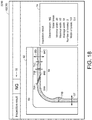
- FIG. 18 is a diagram illustrating an example of display of an inspection result of a case in which it is determined that there is a defect in the coating quality of a coating material.
- the inspection result screen 70 includes an input image 62, an overview display area 72 of the inspection result and a detailed display area 74 of the inspection result.
- the control device 110 displays defective portions on the input image 62.
- the control device 110 displays portions in which an inclined break has occurred on the input image 62 in an emphasized manner compared with the other portions. Accordingly, the user can acquire a portion in which an inclined break has occurred at a glance.
- a method of emphasizing a portion in which an inclined break has occurred is arbitrary.
- the display unit 102 displays a straight line along an inclined break for displaying the portion in which an inclined break has occurred in an emphasized manner.
- a straight line 71A is displayed in a portion in which an inclined break has occurred. Accordingly, a user can easily acquire a direction in which inclined breaks have occurred.
- the display unit 102 displays each portion in which an inclined break has occurred in a color different from that of the other portions.
- the display unit 102 displays a portion in which a coating material is broken in an orthogonal direction in an emphasized manner compared with the other portions.
- a straight line 71B is displayed in a portion in which a coating material is broken in the orthogonal direction.
- the display unit 102 displays a portion in which the line width of the coating material is minimal in an emphasized manner compared with the other portions.
- a mark 71C is displayed in a portion in which the line width is minimal. Accordingly, the user can easily perceive a portion in which the line width is the minimal.
- the display unit 102 displays a portion in which the line width of the coating material is maximal in an emphasized manner compared with the other portions.
- a mark 71D is displayed in a portion in which the line width is the maximal. Accordingly, the user can easily perceive a portion in which the line width is the maximum.
- an overview of the inspection result is displayed. For example, in the overview display area 72, it is displayed whether or not the inspection result is good. When the coating quality of the coating material is good, "OK" is displayed in the overview display area 72. On the other hand, when there is a defect in the coating quality of the coating material, "NG" is displayed in the overview display area 72.
- the inspection result displayed in the overview display area 72 is displayed as being larger than the inspection result displayed in the detailed display area 74. It is difficult for a user to overlook a defective product of the workpiece W by checking the inspection result displayed in the overview display area 72.
- the detailed display area 74 details of the inspection result are displayed. For example, in the detailed display area 74, whether or not an inspection result is good, the state of an inspection object, a minimal coating width of the coating material, a maximal coating width of the coating material, an average coating width of the coating material, the number of breaks of the coating material, and the break width of the coating material are displayed.
- control device 110 specifies a minimal coating width from among line widths calculated on the reference straight lines L1 to L9 (see FIG. 13 ) and displays the minimal coating width in the detailed display area 74.
- the control device 110 specifies a maximum coating width from among line widths calculated on the reference straight lines L1 to L9 and displays the maximal coating width in the detailed display area 74.
- the control device 110 specifies an average coating width of line widths calculated on the reference straight lines L1 to L9 and displays the average coating width in the detailed display area 74.
- the control device 110 displays the number of groups in which the coating areas 64 are grouped by the grouping unit 152 described above as the number of breaks of the coating material in the detailed display area 74.
- the control device 110 calculates a gap between linear parts adjacent to each other as a break width and displays the break width in the detailed display area 74.
- the image processing apparatus 100 groups the coating area 64 for each sequence of linear parts and calculates a line width in the orthogonal direction of the linear part for each grouped linear part in a plurality of portions of the coating area 64. Thereafter, the image processing apparatus 100 detects an inclined break in the coating area 64 based on the calculated line width for each linear part. By calculating the line width for each sequence of linear parts that are grouped, the image processing apparatus 100 can detect a break also when the coating material is broken into three or more parts.
- this embodiment includes the following disclosure.
- An image processing apparatus includes: a grouping unit (152) that is used for extracting coating areas representing a coating material from an input image (30) acquired by imaging an inspection object linearly coated with the coating material and grouping the coating areas for each sequence of linear parts; a calculation unit (154) that is used for calculating a line width in an orthogonal direction of a linear part for each of the linear parts in a plurality of portions of the coating area including end portions of the linear parts; a break detecting unit (156) that is used for detecting a break in the coating material based on the line widths calculated in the plurality of portions; and an output unit (101) that is used for outputting an indication representing occurrence of the break when the break is detected.
- the image processing apparatus according to any one of Configurations 1 to 4, wherein the calculation unit (154) sets straight lines in a plurality of portions of a predetermined reference path such that the straight lines are orthogonal to the reference path representing positions at which the coating material is to be shown in an image, detects two edge points presented on each of the set straight lines for each of the linear parts and calculates a distance between the two edge points as the line width.
- An image processing method including: a step (S54) of extracting coating areas representing a coating material from an input image (30) acquired by imaging an inspection object linearly coated with the coating material and grouping the coating areas for each sequence of linear parts; a step (S58) of calculating a line width in an orthogonal direction of a linear part for each of the linear parts in a plurality of portions of the coating area including end portions of the linear parts; a step (S60) of detecting a break in the coating material based on the line widths calculated in the plurality of portions; and a step (S70) of outputting an indication representing occurrence of the break when the break is detected.
- a non-transitory computer readable recording medium that recording an image processing program executed by a computer, the image processing program causing the computer to execute: a step (S54) of extracting coating areas representing a coating material from an input image (30) acquired by imaging an inspection object linearly coated with the coating material and grouping the coating areas for each sequence of linear parts; a step (S58) of calculating a line width in an orthogonal direction of a linear part for each of the linear parts in a plurality of portions of the coating area including end portions of the linear parts; a step (S60) of detecting a break in the coating material based on the line widths calculated in the plurality of portions; and a step (S70) of outputting an indication representing occurrence of the break when the break is detected.
Landscapes
- Engineering & Computer Science (AREA)
- Physics & Mathematics (AREA)
- General Physics & Mathematics (AREA)
- Computer Vision & Pattern Recognition (AREA)
- Theoretical Computer Science (AREA)
- Quality & Reliability (AREA)
- Analytical Chemistry (AREA)
- General Engineering & Computer Science (AREA)
- Life Sciences & Earth Sciences (AREA)
- Chemical & Material Sciences (AREA)
- Signal Processing (AREA)
- Biochemistry (AREA)
- General Health & Medical Sciences (AREA)
- Immunology (AREA)
- Pathology (AREA)
- Health & Medical Sciences (AREA)
- Manufacturing & Machinery (AREA)
- Automation & Control Theory (AREA)
- Investigating Materials By The Use Of Optical Means Adapted For Particular Applications (AREA)
- Length Measuring Devices By Optical Means (AREA)
- Image Analysis (AREA)
- Manipulator (AREA)
- Image Processing (AREA)
Abstract
Description
- The present invention relates to a technology for detecting a break in a coating material with which an inspection object is coated.
- In the field of factory automation (FA), technologies for automatically inspecting an inspection object such as a workpiece are widely used. As one of automatic inspections, there are technologies for inspecting whether or not a workpiece is coated with a coating material such as a sealing material as is intended. Through the inspection, whether or not a sealing material is broken, whether or not a width of a sealing material is appropriate, whether or not intended places are coated with the sealing material, and the like are detected.
- Relating to a technology for detecting a break in a coating material, Japanese Patent Application Laid-Open No.
2015-132536 - As another example, Japanese Patent Application Laid-Open No.
2010-054289 - As another example, Japanese Patent Application Laid-Open No.
H08-334478 -
- [Patent Document 1] Japanese Patent Application Laid-Open No.
2015-132536 - [Patent Document 2] Japanese Patent Application Laid-Open No.
2010-054289 - [Patent Document 3] Japanese Patent Application Laid-Open No.
H08-334478 - The inspection device disclosed in
Patent Document 1, as described above, tracks a sealing material from the first point set in advance and determines whether or not a sealing material is broken on the basis whether or not the second point can be reached by tracking the sealing material from the first point set in advance. For this reason, while the inspection device can detect whether or not a sealing material is divided, it cannot detect how the sealing material is broken. For example, when a coating material is divided into three or more parts, the inspection device cannot detect that the coating material is divided into three or more parts. - The inspection device disclosed in Patent Document 2, as described above, performs outline tracking from edge points on a first virtual line set in advance and determines the presence/absence of a break in a sealing material based on whether or not the first virtual line or the second virtual line can be arrived at as results of tracking. For this reason, while the inspection device can detect whether or not a sealing material is divided, it cannot detect how the sealing material is broken. For example, when a coating material is divided into three or more parts, the inspection device cannot detect that the coating material is divided into three or more parts.
- The sealing inspection system disclosed in Patent Document 3, as described above, retrieves two edge points from inspection points set in advance and detects a distance between the two edge points as a width of the sealing material. The sealing inspection system can detect that a sealing material is divided into a plurality of parts based on a width of the coating material detected for each inspection point. However, the sealing inspection system retrieves two edge points for each inspection point and accordingly, cannot detect an inclined break representing that a linearly-coated sealing material is diagonally broken with respect to the direction of a line.
- As above, the inspection methods disclosed in
Patent Documents 1 to 3 described above cannot detect both a plurality of breaks in a coating material and an inclined break of a coating material. - For solving the problems described above, an objective of the disclosure according to an aspect is to provide a technology capable of detecting both a break in a plurality of parts in a coating material and an inclined break of a coating material.
- In one example of the disclosure, an image processing apparatus includes a grouping unit that is used for extracting coating areas representing a coating material from an input image acquired by imaging an inspection object linearly coated with the coating material and grouping the coating areas for each sequence of linear parts, a calculation unit that is used for calculating a line width in an orthogonal direction of a linear part for each of the linear parts in a plurality of portions of the coating area including end portions of the linear parts, a break detecting unit that is used for detecting a break in the coating material based on the line widths calculated in the plurality of portions, and an output unit that is used for outputting an indication representing occurrence of a break when the break is detected.
- According to the disclosure, by calculating line widths in a plurality of portions of the coating area for each sequence of linear parts that are grouped, the image processing apparatus can detect both a plurality of breaks in a coating material and an inclined break of the coating material.
- In another example of the disclosure, the output unit displays the input image and displays a portion in which the break has occurred on the input image in an emphasized manner compared with other portions.
- According to the disclosure, a user can perceive a portion in which a break has occurred at a glance.
- In another example, the emphasized displaying includes displaying a straight line along the break.
- According to the disclosure, a user can easily perceive a direction in which a break has occurred.
- In another example of the disclosure, the output unit further displays the number of groups into which the coating area is grouped by the grouping unit as the number of breaks of the coating material.
- According to the disclosure, the user can easily perceive the number of breaks of the coating material.
- In another example of the disclosure, the calculation unit sets straight lines in a plurality of portions of a predetermined reference path such that the straight lines are orthogonal to the reference path representing positions at which the coating material is to be shown in an image and detects two edge points presented on each of the set straight lines for each of the linear parts and calculates a distance between the two edge points as the line width.
- According to the disclosure, an edge point is necessarily presented on a straight line set to be orthogonal to the coating area representing the coating material, and accordingly, the image processing apparatus can accurately calculate the line width.
- In another example of the present disclosure, when a plurality of line widths are calculated for one of the straight lines set in the plurality of portions, the break detecting unit detects the break.
- According to the disclosure, line widths are calculated at a plurality of portions of the coating area for each sequence of linear parts that are grouped, and accordingly, the image processing apparatus can easily detect an inclined break of the coating material.
- In another example of the disclosure, an image processing method includes extracting coating areas representing a coating material from an input image acquired by imaging an inspection object linearly coated with the coating material and grouping the coating areas for each sequence of linear parts, calculating a line width in an orthogonal direction of the linear part for each of the linear parts in a plurality of portions of the coating area including end portions of the linear parts, detecting a break in the coating material based on the line widths calculated in the plurality of portions, and outputting an indication representing occurrence of the break when the break is detected.
- According to the disclosure, by calculating line widths in a plurality of portions of the coating area for each sequence of linear parts that are grouped, the image processing method can detect both a plurality of breaks in a coating material and an inclined break of the coating material.
- In another example of the disclosure, a non-transitory computer readable recording medium recording an image processing program causes the computer to execute: extracting coating areas representing a coating material from an input image acquired by imaging an inspection object linearly coated with the coating material and grouping the coating areas for each sequence of linear parts, calculating a line width in an orthogonal direction of the linear part for each of the linear parts in a plurality of portions of the coating area including end portions of the linear parts, detecting a break in the coating material based on the line widths calculated in the plurality of portions, and outputting an indication representing occurrence of the break when the break is detected.
- According to the disclosure, by calculating line widths in a plurality of portions of the coating area for each sequence of linear parts that are grouped, the image processing program can detect both a plurality of breaks in a coating material and an inclined break of the coating material.
- According to an aspect, both a break in a plurality of parts in a coating material and an inclined break of a coating material can be detected.
-
-
FIG. 1 is a conceptual diagram schematically illustrating an image processing system according to an embodiment; -
FIG. 2 is a diagram illustrating functions of an image processing apparatus according to an embodiment; -
FIG. 3 is a diagram illustrating one example of the entire configuration of an image processing system according to an embodiment; -
FIG. 4 is a schematic diagram illustrating one example of the hardware configuration of an image processing apparatus according to an embodiment; -
FIG. 5 is a flowchart illustrating a setting process executed by an image processing apparatus according to an embodiment; -
FIG. 6 is a diagram illustrating one example of a setting screen displayed in Step S12 illustrated inFIG. 5 ; -
FIG. 7 is a diagram illustrating one example of a setting screen displayed in Step S14 illustrated inFIG. 5 ; -
FIG. 8 is a diagram illustrating one example of a setting screen displayed after a reference path generation button is pressed; -
FIG. 9 is diagram illustrating a flowchart representing an inspection process executed by an image processing apparatus according to an embodiment; -
FIG. 10 is a diagram illustrating an input image acquired from an imaging unit; -
FIG. 11 is a diagram illustrating a binarized image acquired from an input image; -
FIG. 12 is a diagram illustrating one example of results of grouping for a binarized image; -
FIG. 13 is a diagram illustrating one example of a reference straight line set for a coating area; -
FIG. 14 is a diagram illustrating a line width calculating process for a first linear part; -
FIG. 15 is a diagram illustrating a line width calculating process for a second linear part; -
FIG. 16 is a diagram illustrating a line width calculating process for a third linear part; -
FIG. 17 is a diagram illustrating a break detecting process; and -
FIG. 18 is a diagram illustrating an example of display of inspection results when it is determined that there is a defect in the coating quality of a coating material. - Hereinafter, an embodiment of the invention will be described with reference to the drawings. In the following description, the same reference signs are assigned to the same components and the same constituent elements. In addition, the names and the functions thereof are the same. Thus, detailed description thereof will not be repeated.
- First, application examples of the invention will be described with reference to
FIGS. 1 and2 .FIG. 1 is a conceptual diagram schematically illustrating animage processing system 1 according to this embodiment. - The
image processing system 1 is, for example, configured of animaging unit 8 used for imaging an inspection object and animage processing apparatus 100 used for executing predetermined image processing for an image acquired from theimaging unit 8. Theimaging unit 8 may be configured as being separated from theimage processing apparatus 100 or may be configured integrally with theimage processing apparatus 100. - The
image processing apparatus 100 includes acontrol device 110 used for controlling theimage processing apparatus 100 and anoutput unit 101 used for outputting results of an inspection as major components. Thecontrol device 110 includes agrouping unit 152, acalculation unit 154, and abreak detecting unit 156 as major functional components. - The
imaging unit 8 images a workpiece W conveyed on a conveyer and generates an input image representing the workpiece W. The workpiece W is an inspection object and is, for example, a product or a semifinished product. The workpiece W is coated with a coating material 7. The coating material 7 is, for example, an adhesive agent such as a sealing material. Theimaging unit 8 sequentially outputs generatedinput images 30 to thegrouping unit 152 of thecontrol device 110. -
FIG. 2 is a diagram illustrating functions of theimage processing apparatus 100. InFIG. 2 , a part of aninput image 30 is illustrated as aninput image 35. - The
grouping unit 152extracts coating areas 64 representing coating material 7 from theinput image 35 and groups thecoating areas 64 for each sequence of linear parts. In the example illustrated inFIG. 2 , alinear part 64A of thecoating area 64 is grouped as a group G1. Similarly, alinear part 64B of thecoating area 64 is grouped as a group G2. Similarly, alinear part 64C of thecoating area 64 is grouped as a group G3. Results of the grouping using thegrouping unit 152 are output to thecalculation unit 154. As an example, results of grouping include identification information used for identifying the groups G1 to G3, coordinate values of the groups G1 to G3 inside the image, and the like. - The
calculation unit 154 calculates a line width (thickness) of each of thelinear parts 64A to 64C in an orthogonal direction of the linear part at a plurality of portions in thecoating area 64 including end portions of thelinear parts 64A to 64C. An end portion described here does not need to be a tip end of each of thelinear parts 64A to 64C and may represent a portion within a predetermined distance (a predetermined number of pixels) from the tip end of each of thelinear parts 64A to 64C. Details of a method of calculating a line width will be described later. - In the example illustrated in
FIG. 2 , thecalculation unit 154 calculates line widths on reference straight lines L1 to L9. More specifically, for thelinear part 64A, thecalculation unit 154 calculates line widths W1 to W4 and W5A on reference straight lines L1 to L5. For thelinear part 64B, thecalculation unit 154 calculates line widths W5B, W6, and W7 on reference straight lines L5 to L7. For thelinear part 64C, thecalculation unit 154 calculates a line width W9 on a reference straight line L9. The calculated line widths W1 to W4, W5A, W5B, W6, W7, and W9 are output to thebreak detecting unit 156. - The
break detecting unit 156 detects a break in the coating material based on the line widths W1 to W4, W5A, W5B, W6, W7, and W9 calculated for thelinear parts 64A to 64C. While details will be described later, thebreak detecting unit 156, for example, can detect an inclined break representing that a linear coating material is broken by being inclined with respect to a tangential direction of the coating material based on calculation of a plurality of line widths for one of the reference straight lines L1 to L9. In the example illustrated inFIG. 2 , since a plurality of line widths W5A and W5B are detected for one reference straight line L5, thebreak detecting unit 156 detects an inclined break on the reference straight line L5. - The
output unit 101 is a unit that is used for outputting results of an inspection. For example, theoutput unit 101 may be a display unit 102 (seeFIG. 3 ) to be described later, a speaker that outputs sound, an indicator, or any other output device. When a break is detected by thebreak detecting unit 156, theoutput unit 101 outputs an indication representing an occurrence of a break. In the example illustrated inFIG. 1 , acircle 38 is attached to a place at which a break has occurred. - By calculating a line width for each grouped linear part, even when the coating material is divided into three or more parts, the
image processing apparatus 100 can detect a break in the coating material. - The entire configuration of the
image processing system 1 will be described with reference toFIG. 3. FIG. 3 is a diagram illustrating one example of the entire configuration of theimage processing system 1. - The
image processing system 1 includes animage processing apparatus 100 that is also referred to as a visual sensor, a programmable logic controller (PLC) 5 that can communicate with theimage processing apparatus 100, and an imaging unit 8 (an image acquiring unit) that is connected to theimage processing apparatus 100 as major components. - The
PLC 5 executes control of a conveyingmechanism 6 such as a conveyer by cooperating with theimage processing apparatus 100. As an example, in addition to an optical system such as a lens, theimaging unit 8 is configured to include imaging devices, which are partitioned into a plurality of pixels, such as coupled charged devices (CCD) or complementary metal oxide semiconductor (CMOS) sensors. Theimaging unit 8 sequentially images workpieces W conveyed by the conveyingmechanism 6. Input images acquired through imaging using theimaging unit 8 are transmitted to theimage processing apparatus 100. - By executing a predetermined inspection program, the
image processing apparatus 100 inspects whether or not an inspection object is coated with a coating material as is intended. For example, theimage processing apparatus 100 may inspect whether or not a coating material is broken, whether or not a coating width of a coating material is appropriate, whether or not an intended place is coated with a coating material, and the like. Results of the inspection performed by theimage processing apparatus 100 are displayed on thedisplay unit 102. - The hardware configuration of the
image processing apparatus 100 illustrated inFIG. 1 will be described with reference toFIG. 4. FIG. 4 is a schematic diagram illustrating one example of the hardware configuration of theimage processing apparatus 100. - The
image processing apparatus 100, typically, has a structure according to a general-purpose computer architecture, and, by executing a program installed in advance using a processor, various image processes described with reference toFIG. 1 are realized. - More specifically, the
image processing apparatus 100 includes acontrol device 110 such as a central processing unit (CPU) or a micro-processing unit (MPU), a random access memory (RAM) 112, adisplay controller 114, asystem controller 116, an input/output (I/O)controller 118, astorage device 120, acamera interface 122, aninput interface 124, aPLC interface 126, acommunication interface 128, and amemory card interface 130. Such units are interconnected to enable data communication using thesystem controller 116 as a center. - The
control device 110 exchanges a program (code) and the like with thesystem controller 116 and executes them in a predetermined order, thereby realizing a target arithmetic operation process. Thesystem controller 116 is connected to thecontrol device 110, theRAM 112, thedisplay controller 114, and the I/O controller 118 through a bus, performs exchange of data and the like with each unit, and is responsible for the overall process of theimage processing apparatus 100. - The
RAM 112 is, typically a volatile memory such as a dynamic random access memory (DRAM) and stores a program read from thestorage device 120, an input image acquired by theimaging unit 8, results of the processing for the input image, workpiece data, and the like. - The
display controller 114 is connected to thedisplay unit 102 and outputs a signal for displaying various kinds of information to thedisplay unit 102 in accordance with an internal command supplied from thesystem controller 116. Thedisplay unit 102, for example, includes a liquid crystal display, an organic electro luminescence (EL) display, an organic EL, or the like. Thedisplay unit 102, as illustrated inFIG. 4 , may be integrally configured with theimage processing apparatus 100 or may be configured separately from theimage processing apparatus 100. - The I/
O controller 118 controls data exchange with a recording medium or an external device connected to theimage processing apparatus 100. More specifically, the I/O controller 118 is connected to thestorage device 120, thecamera interface 122, theinput interface 124, thePLC interface 126, thecommunication interface 128, and thememory card interface 130. - The
storage device 120 is, typically, a nonvolatile magnetic storage device, and various setting values and the like are stored therein in addition to animage processing program 20 executed by thecontrol device 110. In addition, an input image acquired from theimaging unit 8 is stored in thestorage device 120. Instead of thestorage device 120, a semiconductor memory device such as a flash memory or an optical memory device such as a digital versatile disk random access memory (DVD-RAM) may be employed. - The
camera interface 122 corresponds to an input unit that receives image data generated by imaging a workpiece W (inspection object) and relays data transmission between thecontrol device 110 and theimaging unit 8. More specifically, thecamera interface 122 can be connected to one ormore imaging units 8, an imaging instruction being output from thecontrol device 110 to theimaging units 8 through thecamera interface 122. Accordingly, theimaging unit 8 images a subject and outputs a generated image to thecontrol device 110 through thecamera interface 122. - The
input interface 124 relays data transmission between thecontrol device 110 and input devices such as akeyboard 104, a mouse, a touch panel, and a dedicated console. In other words, theinput interface 124 accepts an operation instruction given by a user operating an input device. - The PLC interface 126 relays data transmission between the
PLC 5 and thecontrol device 110. More specifically, thePLC interface 126 transmits information relating to the state of a production line, information relating to a workpiece W, and the like controlled by thePLC 5 to thecontrol device 110. - The
communication interface 128 relays data transmission between thecontrol device 110 and another personal computer, a server apparatus, or the like not illustrated in the drawings. Thecommunication interface 128 is, typically, configured using Ethernet (registered trademark), a universal serial bus (USB), or the like. Instead of a type in which a program stored in amemory card 106 is installed in theimage processing apparatus 100, a program downloaded into a transfer server or the like through thecommunication interface 128 may be installed in theimage processing apparatus 100. For example, thecommunication interface 128 may receive a signal indicating the state of theimaging unit 8 from theimaging unit 8, thePLC 5, or the like. - The signal indicates whether or not the
imaging unit 8 is performing imaging. - The
memory card interface 130 relays data transmission between thecontrol device 110 and thememory card 106 serving as a recording medium. In other words, in thememory card 106, animage processing program 20 and the like executed by theimage processing apparatus 100 is distributed and stored, and thememory card interface 130 reads theimage processing program 20 from thememory card 106. In addition, in response to an internal command of thecontrol device 110, thememory card interface 130 writes a camera image acquired by theimaging unit 8 and/or results of the process performed by theimage processing apparatus 100, and the like in thememory card 106. Thememory card 106 is configured using a general semiconductor memory device such as a secure digital (SD) card, a magnetic recording medium such as a flexible disk, an optical recording medium such as a compact disk read only memory (CD-ROM), or the like. - When a computer having a structure according to the general computer architecture as described above is used, in addition to the applications used for providing functions according to this embodiment, an operating system (OS) used for providing basic functions of the computer may be installed. In such a case, the image processing program according to this embodiment may execute a process of calling necessary modules in a predetermined order and/or at a predetermined timing among programs modules provided as a part of the OS. In other words, the program according to this embodiment may not include the modules as described above, and there are also cases in which processes are executed by cooperation with the OS. Accordingly, the image processing program according to this embodiment may have a form not including some of such modules.
- In addition, the image processing program according to this embodiment may be embedded into a part of another program. Also in such a case, the program does not need to include modules included in the other program in which the program is embedded, and the process may be executed by cooperation with the other program. In other words, the image processing program according to this embodiment may have a form of being embedded into such another program.
- In addition, alternatively, some or all of the functions provided by executing the image processing program may be embedded as a dedicated hardware circuit.
- An inspection flow using the
image processing apparatus 100 will be described with reference toFIGS. 5 to 18 . The inspection flow using theimage processing apparatus 100 can be roughly divided into a setting process and an inspection process. The setting process is a process executed before the inspection process and is performing setting of parameters of various kinds of image processing executed in the inspection process. In the inspection process, theimage processing apparatus 100 executes an inspection process for the coating quality of a coating material in accordance with various parameters set in the setting process. - The setting process and the inspection process are realized by the
control device 110 of theimage processing apparatus 100 executing a program. In another aspect, a part or the whole of the process may be executed by circuit elements or any other hardware. - Hereinafter, the setting process and the inspection process executed by the
image processing apparatus 100 will be sequentially described. - First, the setting process executed by the
control device 110 of theimage processing apparatus 100 will be described with reference toFIGS. 5 to 9 .FIG. 5 is a flowchart illustrating the setting process executed by thecontrol device 110. - In Step S10, the
control device 110 outputs an imaging instruction to theimaging unit 8 and causes theimaging unit 8 to image a workpiece linearly coated with a coating material. Accordingly, thecontrol device 110 acquires a reference image representing a workpiece coated with a coating material. The reference image acquired in Step S10 is acquired by imaging a workpiece that is normally coated with a coating material and is an image that becomes a model of the coating quality of a coating material. - In Step S12, the
control device 110 accepts color settings used for designating the range of colors of the coating material.FIG. 6 is a diagram illustrating one example of asetting screen 10 displayed in Step S12. - As illustrated in
FIG. 6 , thesetting screen 10 includes a tab TB used for displaying various setting screens. When "color designation" of the tab TB is selected, acolor setting screen 10A used for designating the range of colors of the coating material is displayed. Thecolor setting screen 10A includes acolor setting area 31, animage display area 32A, anOK button 46, and a cancelbutton 48. - In the
color setting area 31, a user can input a setting of a hue range of the coating material, a setting of a saturation range of the coating material, and a setting of a lightness range of the coating material. Hereinafter, the hue range, the saturation range, and the lightness range will be collectively referred to as a "color range." Thecolor setting area 31 includes apointer designation area 31A in which a setting of the color range of the coating material is accepted through pointer designation and a numericalvalue input area 31B in which a setting of the color range of the coating material is accepted through a numeral value input. - The setting of the hue range of the coating material is set using a pointer H1 used for setting a lower limit value of the hue and a pointer H2 used for setting an upper limit value of the hue. The pointers H1 and H2 are configured to be slidable in the horizontal direction on the sheet face using a mouse operation or a touch operation. A range designated by the pointers H1 and H2 is set as the hue range of the coating material.
- The setting of the saturation range of the coating material is set using a pointer C1 used for setting a lower limit value of the saturation and a pointer C2 used for setting an upper limit value of the saturation. The pointers C1 and C2 are configured to be slidable in the vertical direction on the sheet face using a mouse operation or a touch operation. A range designated by the pointers C1 and C2 is set as the saturation range of the coating material.
- The setting of the lightness range of the coating material is set using a pointer B1 used for setting a lower limit value of the lightness and a pointer B2 used for setting an upper limit value of the lightness. The pointers B1 and B2 are configured to be slidable in the vertical direction on the sheet face using a mouse operation or a touch operation. A range designated by the pointers B1 and B2 is set as the lightness range of the coating material.
- A user, in the numerical
value input area 31B, can input the lower limit value of the hue, the upper limit value of the hue, the lower limit value of the saturation, the upper limit value of the saturation, the lower limit value of the lightness, and the upper limit value of the lightness as numerical values. Typically, positions of the pointers in thepointer designation area 31A and numerical values in the numericalvalue input area 31B are linked with each other. - The
control device 110 binarizes the reference image in accordance with the color range designated in thecolor setting area 31. For example, when each pixel of the reference image is included in the color range designated in thecolor setting area 31, thecontrol device 110 sets the value of these pixels as "1." On the other hand, when each pixel of the reference image is not included in the color range designated in thecolor setting area 31, thecontrol device 110 sets the value of these pixels as "0." Accordingly, thecontrol device 110 generates a binarized image from the reference image. The binarized image is displayed in theimage display area 32A. Preferably, thecontrol device 110 links the display of a binarized image displayed in theimage display area 32A with the setting for thecolor setting area 31. A user can easily perform setting of the color range of a coating material by performing setting for thecolor setting area 31 while checking the binarized image. - When the user presses the
OK button 46, thecontrol device 110 stores the setting of the color range set in thecolor setting area 31 in the storage device 120 (seeFIG. 4 ). On the other hand, when the user presses the cancelbutton 48, thecontrol device 110 closes the display of thecolor setting screen 10A without storing the setting of the color range set in thecolor setting area 31. - Referring back to
FIG. 5 , in Step S14, thecontrol device 110 accepts a setting of a start position and an end position of a range to be coated with a coating material.FIG. 7 is a diagram illustrating one example of thesetting screen 10 displayed in Step S14. - As illustrated in
FIG. 7 , when "area setting" of the tab TB is selected, anarea setting screen 10B for designating a range to be coated with a coating material is displayed. Thearea setting screen 10B includes awidth designation area 51, a measurementarea registration button 52, a startline registration button 53, an endline registration button 54, a referencepath generation button 55, acheck box 56, anOK button 57, and a cancelbutton 58. - In the
image display area 32A, the reference image acquired in Step S10 described above or a binarized image acquired from the reference image based on the color range set in Step S12 described above is displayed. Thecontrol device 110 performs sequential switching of a display of the reference image and the binarized image in accordance with an operation for thecheck box 56. More specifically, when "check" is not inserted into thecheck box 56, thecontrol device 110 displays the reference image in theimage display area 32A. On the other hand, when "check" is inserted into thecheck box 56, thecontrol device 110 displays the binarized image in theimage display area 32A. - In the
width designation area 51, a user can set an allowed width of a path to be coated with the coating material in units of pixels. In the inspection process to be described later, when the coating material exceeds the allowed width, "NG" is acquired as results of the inspection. - The measurement
area registration button 52 accepts registration of an image area to be inspected. More specifically, a user performs area designation for an image displayed in theimage display area 32A. For example, the designation of the area is realized through a mouse operation, a touch operation, or the like. When the user presses the measurementarea registration button 52 after the area designation, thecontrol device 110 stores the designated inspection object area in the storage device 120 (seeFIG. 4 ). Accordingly, an image area to be inspected and an image area not to be inspected are distinguished from each other. - The start
line registration button 53 accepts registration of a start position of a range to be coated with a coating material. More specifically, a user can designate a start position of acoating area 36A for an image displayed in theimage display area 32A. In the example illustrated inFIG. 7 , a start line ST is set as the start position. The setting of the start line ST is, for example, realized through a mouse operation, a touch operation, or the like. The start line ST is set such that it traverses thecoating area 36A. When the user presses the startline registration button 53 after the setting of the start line ST, thecontrol device 110 stores the position (coordinate values) of the start line ST inside the image in the storage device 120 (seeFIG. 4 ). - The end
line registration button 54 accepts registration of an end position of a range to be coated with the coating material. More specifically, a user can designate an end position of thecoating area 36A for the image displayed in theimage display area 32A. In the example illustrated inFIG. 7 , an end line ED is set as the end position. The setting of the end line ED is, for example, realized through a mouse operation, a touch operation, or the like. The end line ED is set such that it traverses thecoating area 36A. When the user presses the endline registration button 54 after the setting of the end line ED, thecontrol device 110 stores the position (coordinate values) of the end line ED inside the image in the storage device 120 (seeFIG. 4 ). - The reference
path generation button 55 is a button used for executing a process of automatically calculating a range to be coated with a coating material. Thecontrol device 110 executes the process of Step S16 illustrated inFIG. 5 based on reception of pressing of the referencepath generation button 55. - More specifically, in Step S16, the
control device 110 applies a differential filter for a binarized image acquired from the reference image based on the color range set in Step S12 described above, thereby generating a differential image representing an edge portion (gradient). For example, in the differential image, a pixel value of an edge portion is represented as "1," and a pixel value of a non-edge portion is represented as "0." Thecontrol device 110 detects two edge points (in other words, start points SP1 and SP2) of which pixel values are "1" on the start line ST and detects two edge points (end points EP1 and EP2) of which pixel values are "1" on the end line ED. Thecontrol device 110 searches for an edge point for pixels adjacent to the start point SP1 on the differential image in the counterclockwise direction. When an edge point is retrieved, thecontrol device 110 stores coordinate values of the edge point and sets the edge point as a target pixel. Thereafter, thecontrol device 110 searches for an edge point for pixels adjacent to the target pixel on the differential image in the counterclockwise direction. By repeating such a process, thecontrol device 110 detects a group of coordinate values of edge points from the start point SP1 to the end point EP1 as anoutline 38A. Similarly, thecontrol device 110 detects a group of coordinate values of edge points from the start point SP2 to the end point EP2 as anoutline 38B. -
FIG. 8 is a diagram illustrating one example of thesetting screen 10 displayed after the referencepath generation button 55 is pressed. As illustrated inFIG. 8 , thecontrol device 110 specifies allowed coating ranges 39A and 39B that are allowed as coating positions of the coating material based on theoutlines control device 110 extends ranges surrounded by theoutlines width designation area 51 and specifies the ranges after the extension as allowed coating ranges 39A and 39B. - In addition, the
control device 110 specifies a center line of theoutlines reference path 40 representing positions to be coated with the coating material. More specifically, thecontrol device 110 specifies a corresponding point on theoutline 38B for each point on theoutline 38A. For example, thecontrol device 110 specifies points on theoutline 38B having shortest distances from points on theoutline 38A as corresponding points. Thecontrol device 110 specifies a line connecting midpoints between the corresponding points on theoutlines reference path 40. - When the pressing of the
OK button 57 is detected, thecontrol device 110 executes the process of Step S18 illustrated inFIG. 5 . More specifically, in Step S18, thecontrol device 110 stores the allowed coating ranges 39A and 39B and thereference path 40 specified in Step S16 in the storage device 120 (seeFIG. 4 ). When the pressing of the cancelbutton 58 is detected, thecontrol device 110 closes the display of thearea setting screen 10B without storing the allowed coating ranges 39A and 39B and thereference path 40. - Next, the inspection process executed by the
control device 110 of theimage processing apparatus 100 will be described with reference toFIGS. 9 to 18 .FIG. 9 is diagram illustrating a flowchart representing the inspection process executed by thecontrol device 110. Thecontrol device 110 performs an inspection of the coating quality of a coating material in accordance with various parameters set in the setting process described above. - More specifically, in Step S50, the
control device 110 outputs an imaging instruction to theimaging unit 8 and causes theimaging unit 8 to image a workpiece linearly coated with a coating material. Accordingly, thecontrol device 110 acquires an input image representing the workpiece coated with the coating material.FIG. 10 is a diagram illustrating aninput image 62 acquired from theimaging unit 8. In the example illustrated inFIG. 10 , theinput image 62 includes aworkpiece area 63 representing a workpiece and acoating area 64 representing a coating material. Thecoating area 64 is divided intolinear parts 64A to 64C. - Referring back to
FIG. 9 , in Step S52, thecontrol device 110 extracts thecoating area 64 from theinput image 62. More specifically, thecontrol device 110 binarizes the input image in accordance with the color range of the coating material set in the setting process described above. For example, when each pixel of the input image is included in the set color range, thecontrol device 110 sets the value of the pixel as "1." On the other hand, when each pixel of the input image is not included in the set color range, thecontrol device 110 sets the value of the pixel as "0." In other words, pixels of which pixel values are "1" are extracted as a coating area representing the coating material.FIG. 11 is a diagram illustrating thebinarized image 65 acquired from theinput image 62. As illustrated inFIG. 11 , in thebinarized image 65, only thecoating area 64 is extracted. - Referring back to
FIG. 9 , in Step S54, thecontrol device 110 serving as the grouping unit 152 (seeFIG. 1 ) described above groups thecoating area 64 for each sequence of linear parts. For example, thecontrol device 110 applies a differential filter to thebinarized image 65, thereby generating a differential image representing an edge portion (gradient). In the differential image, a pixel value of an edge portion is represented as "1," and a pixel value of a non-edge portion is represented as "0." Thereafter, thecontrol device 110 performs raster scanning of the differential image and searches for a pixels of which a pixel value is "1." When the pixel of which the pixel value is "1" is retrieved, thecontrol device 110 sets the pixel as a start point. Thecontrol device 110 searches for edge points in the vicinity of the start point in the counterclockwise direction. When an edge point is retrieved, thecontrol device 110 stores coordinate values of the edge point and sets the edge point as a target pixel. Thereafter, thecontrol device 110 searches for an edge point for pixels adjacent to the target pixel on the differential image in the counterclockwise direction. Thecontrol device 110 executes such an outline tracking process until the target point is returned to the start point. Thecontrol device 110 detects a group of coordinate values stored in the process of outline tracking as an outline and specifies an area surrounded by the outline as one group. - At this time, preferably, when the area of each group is smaller than a first threshold, the
control device 110 regards the group as noise. On the other hand, when the area of each group is greater than a second threshold (> the first threshold), thecontrol device 110 regards the group as noise. In other words, when the area of each group is equal to or greater than the first threshold and equal to or less than the second threshold, thecontrol device 110 regards the group as a linear part. -
FIG. 12 is a diagram illustrating one example of results of grouping for thebinarized image 65. In the example illustrated inFIG. 12 , alinear part 64A of thecoating area 64 is grouped as a group G1, alinear part 64B of thecoating area 64 is grouped as a group G2, and alinear part 64C of thecoating area 64 is grouped as a group G3. - Referring back to
FIG. 9 , in Step S56, thecontrol device 110 serving as the calculation unit 154 (seeFIG. 1 ) described above sets a reference straight line such that it is orthogonal to the tangential direction of thereference path 40 in a plurality of places on the reference path 40 (seeFIG. 8 ) set in the setting process described above.FIG. 13 is a diagram illustrating one example of a reference straight line set for thecoating area 64. In the example illustrated inFIG. 13 , reference straight lines L1 to L9 are set. - Referring back to
FIG. 9 , in Step S58, for each of thelinear parts 64A to 64C, thecontrol device 110 serving as the calculation unit 154 (seeFIG. 1 ) described above detects two edge points present on each of the reference straight lines L1 to L9 and calculates a distance between the two edge points as a line width. More specifically, thecontrol device 110 applies a differential filter to thebinarized image 65, thereby generating a differential image representing an edge portion (gradient). For example, in the differential image, a pixel value of an edge portion is represented as "1," and a pixel value of a non-edge portion is represented as "0." Thecontrol device 110 scans the reference straight lines L1 to L9 on the differential image and searches for at least two edge points of which pixel values are "1." Thecontrol device 110 calculates a distance between the two edge points as a line width. Typically, when three or more edge points are present, thecontrol device 110 calculates a distance between two edge points present on the outermost side as a line width. - The process of calculating a line width is performed for each grouped linear part.
FIG. 14 is a diagram illustrating a line width calculating process for alinear part 64A. InFIG. 14 , abinarized image 65A representing thelinear part 64A is illustrated. In Step S58A, thecontrol device 110 calculates a line width at places at which thelinear part 64A and the reference straight lines L1 to L7 overlap each other. In the example illustrated inFIG. 14 , thecontrol device 110 detects edge points E1A and E1B on the reference straight line L1 and calculates a distance between the edge points E1A and E1B as a line width W1. Similarly, a line width W2 is calculated for the reference straight line L2. A line width W3 is calculated for the reference straight line L3. A line width W4 is calculated for the reference straight line L4. A line width W5 is calculated for the reference straight line L5. A line width W6 is calculated for the reference straight line L6. A line width W7A is calculated for the reference straight line L7. -
FIG. 15 is a diagram illustrating a line width calculating process for alinear part 64B. InFIG. 15 , abinarized image 65B representing thelinear part 64B is illustrated. In Step S58B, thecontrol device 110 calculates a line width at places at which thelinear part 64B and the reference straight lines L7 and L8 overlap each other. In the example illustrated inFIG. 15 , a line width W7B is calculated for the reference straight line L7. A line width W8 is calculated for the reference straight line L8. -
FIG. 16 is a diagram illustrating a line width calculating process for alinear part 64C. InFIG. 16 , abinarized image 65C representing thelinear part 64C is illustrated. In Step S58C, thecontrol device 110 calculates a line width at a place at which thelinear part 64C and the reference straight line L9 overlap each other. In the example illustrated inFIG. 16 , a line width W9 is calculated for the reference straight line L9. - Referring back to
FIG. 9 , in Step S60, thecontrol device 110 serving as the break detecting unit 156 (seeFIG. 1 ) described above determines whether or not a break has occurred in the coating material based on the line widths calculated on the reference straight lines L1 to L9 and results of the grouping in Step S54.FIG. 17 is a diagram illustrating a break detecting process. As illustrated inFIG. 17 , thecontrol device 110 detects a break in the coating material when the number of groups acquired in Step S54 is two or more and detects an inclined break when a plurality of line widths are calculated for one of the reference straight lines L1 to L9. In the example illustrated inFIG. 17 , since a plurality of line widths W7A and W7B are detected for one reference straight line L7, thecontrol device 110 determines that an inclined break has occurred on the reference straight line L7. In addition, since the coating material is grouped into three groups in Step S54, thecontrol device 110 determines that the coating material is divided into three parts. - A method of detecting an inclined break is not limited to the method described above, and any arbitrary method may be employed. For example, the
control device 110 detects an inclined break when a line width calculated at an end portion of thelinear parts 64A to 64C is equal to or less than a predetermined value. In the example illustrated inFIG. 17 , when the line widths W7A and W7B are equal to or less than a predetermined value, thecontrol device 110 determines that an inclined break has occurred on the reference straight line L7. - Referring back to
FIG. 9 , in Step S62, thecontrol device 110 determines whether or not a deviation has occurred in a coating position of the coating material based on the allowed coating ranges 39A and 39B (seeFIG. 8 ) set in the setting process described above. More specifically, thecontrol device 110 executes an outline tracking process starting from the start line ST set in the setting process described above and detects the outline of thecoating area 64. The outline tracking process is as described with reference toFIG. 7 , and thus, description thereof will not be repeated here. When all the outlines of thecoating area 64 are included in the allowed coating ranges 39A and 39B, thecontrol device 110 determines that a deviation in the coating position of the coating material has not occurred. On the other hand, when some of outlines of thecoating area 64 are not included in the allowed coating ranges 39A and 39B, thecontrol device 110 determines that a deviation in the coating position of the coating material has occurred. - In Step S64, the
control device 110 determines whether or not the line width of the coating material is within an allowed range. More specifically, when line widths calculated on the reference straight lines L1 to L9 (seeFIG. 13 ) are below the lower limit value set in advance or when line widths calculated on the reference straight lines L1 to L9 are above the upper limit value set in advance, thecontrol device 110 determines that that is a defect in the line width of the coating material. Otherwise, thecontrol device 110 determines that there is no defect in the coating material. - In Step S70, the
control device 110 causes thedisplay unit 102 to display an inspection result.FIG. 18 is a diagram illustrating an example of display of an inspection result of a case in which it is determined that there is a defect in the coating quality of a coating material. - In
FIG. 18 , aninspection result screen 70 is illustrated. Theinspection result screen 70 includes aninput image 62, an overview display area 72 of the inspection result and adetailed display area 74 of the inspection result. - The
control device 110 displays defective portions on theinput image 62. For example, thecontrol device 110 displays portions in which an inclined break has occurred on theinput image 62 in an emphasized manner compared with the other portions. Accordingly, the user can acquire a portion in which an inclined break has occurred at a glance. - A method of emphasizing a portion in which an inclined break has occurred is arbitrary. In an aspect, the
display unit 102 displays a straight line along an inclined break for displaying the portion in which an inclined break has occurred in an emphasized manner. In the example illustrated inFIG. 18 , astraight line 71A is displayed in a portion in which an inclined break has occurred. Accordingly, a user can easily acquire a direction in which inclined breaks have occurred. In another aspect, thedisplay unit 102 displays each portion in which an inclined break has occurred in a color different from that of the other portions. - In addition, the
display unit 102 displays a portion in which a coating material is broken in an orthogonal direction in an emphasized manner compared with the other portions. In the example illustrated inFIG. 18 , astraight line 71B is displayed in a portion in which a coating material is broken in the orthogonal direction. - In addition, the
display unit 102 displays a portion in which the line width of the coating material is minimal in an emphasized manner compared with the other portions. In the example illustrated inFIG. 18 , amark 71C is displayed in a portion in which the line width is minimal. Accordingly, the user can easily perceive a portion in which the line width is the minimal. - In addition, the
display unit 102 displays a portion in which the line width of the coating material is maximal in an emphasized manner compared with the other portions. In the example illustrated inFIG. 18 , amark 71D is displayed in a portion in which the line width is the maximal. Accordingly, the user can easily perceive a portion in which the line width is the maximum. - In the overview display area 72, an overview of the inspection result is displayed. For example, in the overview display area 72, it is displayed whether or not the inspection result is good. When the coating quality of the coating material is good, "OK" is displayed in the overview display area 72. On the other hand, when there is a defect in the coating quality of the coating material, "NG" is displayed in the overview display area 72. The inspection result displayed in the overview display area 72 is displayed as being larger than the inspection result displayed in the
detailed display area 74. It is difficult for a user to overlook a defective product of the workpiece W by checking the inspection result displayed in the overview display area 72. - In the
detailed display area 74, details of the inspection result are displayed. For example, in thedetailed display area 74, whether or not an inspection result is good, the state of an inspection object, a minimal coating width of the coating material, a maximal coating width of the coating material, an average coating width of the coating material, the number of breaks of the coating material, and the break width of the coating material are displayed. - More specifically, the
control device 110 specifies a minimal coating width from among line widths calculated on the reference straight lines L1 to L9 (seeFIG. 13 ) and displays the minimal coating width in thedetailed display area 74. Thecontrol device 110 specifies a maximum coating width from among line widths calculated on the reference straight lines L1 to L9 and displays the maximal coating width in thedetailed display area 74. In addition, thecontrol device 110 specifies an average coating width of line widths calculated on the reference straight lines L1 to L9 and displays the average coating width in thedetailed display area 74. Furthermore, thecontrol device 110 displays the number of groups in which thecoating areas 64 are grouped by thegrouping unit 152 described above as the number of breaks of the coating material in thedetailed display area 74. In addition, thecontrol device 110 calculates a gap between linear parts adjacent to each other as a break width and displays the break width in thedetailed display area 74. - As described above, the
image processing apparatus 100 groups thecoating area 64 for each sequence of linear parts and calculates a line width in the orthogonal direction of the linear part for each grouped linear part in a plurality of portions of thecoating area 64. Thereafter, theimage processing apparatus 100 detects an inclined break in thecoating area 64 based on the calculated line width for each linear part. By calculating the line width for each sequence of linear parts that are grouped, theimage processing apparatus 100 can detect a break also when the coating material is broken into three or more parts. - As described above, this embodiment includes the following disclosure.
- An image processing apparatus includes: a grouping unit (152) that is used for extracting coating areas representing a coating material from an input image (30) acquired by imaging an inspection object linearly coated with the coating material and grouping the coating areas for each sequence of linear parts; a calculation unit (154) that is used for calculating a line width in an orthogonal direction of a linear part for each of the linear parts in a plurality of portions of the coating area including end portions of the linear parts; a break detecting unit (156) that is used for detecting a break in the coating material based on the line widths calculated in the plurality of portions; and an output unit (101) that is used for outputting an indication representing occurrence of the break when the break is detected.
- The image processing apparatus according to
Configuration 1, wherein the output unit (101) displays the input image (30) and displays a portion in which the break has occurred on the input image (30) in an emphasized manner compared with other portions. - The image processing apparatus according to Configuration 2, wherein the emphasized displaying includes displaying a straight line along the break.
- The image processing apparatus according to any one of
Configurations 1 to 3, wherein the output unit (101) further displays a number of groups into which the coating area is grouped by the grouping unit (152) as a number of breaks of the coating material. - The image processing apparatus according to any one of
Configurations 1 to 4, wherein the calculation unit (154) sets straight lines in a plurality of portions of a predetermined reference path such that the straight lines are orthogonal to the reference path representing positions at which the coating material is to be shown in an image, detects two edge points presented on each of the set straight lines for each of the linear parts and calculates a distance between the two edge points as the line width. - The image processing apparatus according to
Configuration 5, wherein, when a plurality of line widths are calculated for one of the straight lines set in the plurality of portions, the break detecting unit (156) detects the break. - An image processing method including: a step (S54) of extracting coating areas representing a coating material from an input image (30) acquired by imaging an inspection object linearly coated with the coating material and grouping the coating areas for each sequence of linear parts; a step (S58) of calculating a line width in an orthogonal direction of a linear part for each of the linear parts in a plurality of portions of the coating area including end portions of the linear parts; a step (S60) of detecting a break in the coating material based on the line widths calculated in the plurality of portions; and a step (S70) of outputting an indication representing occurrence of the break when the break is detected.
- A non-transitory computer readable recording medium that recording an image processing program executed by a computer, the image processing program causing the computer to execute: a step (S54) of extracting coating areas representing a coating material from an input image (30) acquired by imaging an inspection object linearly coated with the coating material and grouping the coating areas for each sequence of linear parts; a step (S58) of calculating a line width in an orthogonal direction of a linear part for each of the linear parts in a plurality of portions of the coating area including end portions of the linear parts; a step (S60) of detecting a break in the coating material based on the line widths calculated in the plurality of portions; and a step (S70) of outputting an indication representing occurrence of the break when the break is detected.
-
- 1 Image processing system
- 5 PLC
- 6 Conveying mechanism
- 7 Coating material
- 8 Imaging unit
- 10 Setting screen
- 10A Color setting screen
- 10B Area setting screen
- 20 Image processing program
- 30, 35, 62 Input image
- 31 Color setting area
- 31A Pointer designation area
- 31B Numerical value input area
- 32A Image display area
- 36A, 64 Coating area
- 38 Circle
- 38A, 38B Outline
- 39A, 39B Allowed coating range
- 40 Reference path
- 46, 57 OK button
- 48, 58 Cancel button
- 51 Designation area
- 52 Measurement area registration button
- 53 Start line registration button
- 54 End line registration button
- 55 Reference path generation button
- 56 Check box
- 63 Workpiece area
- 64A, 64B, 64C Linear part
- 65, 65A, 65B, 65C Binarized image
- 70 Inspection result screen
- 71A, 71B Straight line
- 71C, 71D Mark
- 72 Overview display area
- 74 Detailed display area
- 100 Image processing apparatus
- 101 Output unit
- 102 Display unit
- 104 Keyboard
- 106 Memory card
- 110 Control device
- 112 RAM
- 114 Display controller
- 116 System controller
- 118 I/O controller
- 120 Storage device
- 122 Camera interface
- 124 Input interface
- 126 PLC interface
- 128 Communication interface
- 130 Memory card interface
- 152 Grouping unit
- 154 Calculation unit
- 156 Detection unit
Claims (8)
- An image processing apparatus (100), characterized in that, the image processing apparatus (100) comprises:a grouping unit (152) that extracts coating areas representing a coating material from an input image (30) acquired by imaging an inspection object linearly coated with the coating material and groups the coating areas for each sequence of linear parts;a calculation unit (154) that calculates a line width in an orthogonal direction of the linear part for each of the linear parts in a plurality of portions of the coating area including end portions of the linear parts;a break detecting unit (156) that detects a break in the coating material based on the line widths calculated in the plurality of portions; andan output unit (101) that outputs an indication representing occurrence of a break when the break is detected.
- The image processing apparatus (100) according to claim 1, wherein the output unit (101) displays the input image (30) and displays a portion in which the break has occurred on the input image (30) in an emphasized manner compared with other portions.
- The image processing apparatus (100) according to claim 2, wherein the emphasized displaying includes displaying a straight line along the break.
- The image processing apparatus (100) according to any one of claims 1 to 3, wherein the output unit (101) further displays a number of groups into which the coating area is grouped by the grouping unit (152) as a number of breaks of the coating material.
- The image processing apparatus (100) according to any one of claims 1 to 4, wherein the calculation unit (154) sets straight lines in a plurality of portions of a predetermined reference path such that the straight lines are orthogonal to the reference path representing positions at which the coating material is to be shown in an image and detects two edge points presented on each of the set straight lines for each of the linear parts and calculates a distance between the two edge points as the line width.
- The image processing apparatus (100) according to claim 5, wherein, when a plurality of line widths are calculated for one of the straight lines set in the plurality of portions, the break detecting unit (156) detects the break.
- An image processing method, characterized in that, the image processing method comprises:extracting (S54) coating areas representing a coating material from an input image (30) acquired by imaging an inspection object linearly coated with the coating material and grouping the coating areas for each sequence of linear parts;calculating (S58) a line width in an orthogonal direction of the linear part for each of the linear parts in a plurality of portions of the coating area including end portions of the linear parts;detecting (S60) a break in the coating material based on the line widths calculated in the plurality of portions; andoutputting (S70) an indication representing occurrence of the break when the break is detected.
- A non-transitory computer readable recording medium recording an image processing program executed by a computer, characterized in that, the image processing program causing the computer to execute:extracting (S54) coating areas representing a coating material from an input image (30) acquired by imaging an inspection object linearly coated with the coating material and grouping the coating areas for each sequence of linear parts;calculating (S58) a line width in an orthogonal direction of the linear part for each of the linear parts in a plurality of portions of the coating area including end portions of the linear parts;detecting (S60) a break in the coating material based on the line widths calculated in the plurality of portions; andoutputting (S70) an indication representing occurrence of the break when the break is detected.
Applications Claiming Priority (1)
| Application Number | Priority Date | Filing Date | Title |
|---|---|---|---|
| JP2017209294A JP6965693B2 (en) | 2017-10-30 | 2017-10-30 | Image processing equipment, image processing methods, and image processing programs |
Publications (2)
| Publication Number | Publication Date |
|---|---|
| EP3477588A1 true EP3477588A1 (en) | 2019-05-01 |
| EP3477588B1 EP3477588B1 (en) | 2020-10-28 |
Family
ID=63685562
Family Applications (1)
| Application Number | Title | Priority Date | Filing Date |
|---|---|---|---|
| EP18193424.1A Not-in-force EP3477588B1 (en) | 2017-10-30 | 2018-09-10 | Image processing apparatus, image processing method, and recording medium |
Country Status (4)
| Country | Link |
|---|---|
| US (1) | US10852244B2 (en) |
| EP (1) | EP3477588B1 (en) |
| JP (1) | JP6965693B2 (en) |
| CN (1) | CN109727225B (en) |
Families Citing this family (2)
| Publication number | Priority date | Publication date | Assignee | Title |
|---|---|---|---|---|
| CN115496724A (en) * | 2022-09-22 | 2022-12-20 | 深圳市凌云视迅科技有限责任公司 | Line width detection method and device and storage medium |
| CN120791966B (en) * | 2025-09-15 | 2026-01-09 | 泰山石膏(四川)有限公司 | Control method, device, equipment and medium for edge sealing of gypsum plaster board |
Citations (5)
| Publication number | Priority date | Publication date | Assignee | Title |
|---|---|---|---|---|
| JPH08334478A (en) | 1995-06-09 | 1996-12-17 | Three Bond Co Ltd | Seal inspection system |
| JP2010054289A (en) | 2008-08-27 | 2010-03-11 | Omron Corp | Visual inspection system |
| JP2011095090A (en) * | 2009-10-29 | 2011-05-12 | Ihi Corp | Device and method for inspecting coated state, and program |
| JP2012237681A (en) * | 2011-05-12 | 2012-12-06 | Ihi Corp | Device and method for inspecting coated state, and program |
| JP2015132536A (en) | 2014-01-14 | 2015-07-23 | セイコーエプソン株式会社 | Inspection device and inspection method |
Family Cites Families (11)
| Publication number | Priority date | Publication date | Assignee | Title |
|---|---|---|---|---|
| JP3076515B2 (en) * | 1995-12-25 | 2000-08-14 | 松下電工株式会社 | Flow coat coating state detection method and apparatus |
| JP2002096018A (en) * | 2000-09-22 | 2002-04-02 | Daihatsu Motor Co Ltd | Inspection method and coating width measurement method |
| JP2007229567A (en) * | 2006-02-28 | 2007-09-13 | Fuji Heavy Ind Ltd | Application state inspection system for coating agent |
| JP2009139248A (en) * | 2007-12-07 | 2009-06-25 | Hitachi High-Technologies Corp | Surface defect inspection system equipped with defect detection optical system and defect detection image processing |
| JP2013002957A (en) * | 2011-06-16 | 2013-01-07 | Ihi Corp | Apparatus, method and program for coating state inspection |
| KR101306289B1 (en) * | 2011-09-15 | 2013-09-09 | (주) 인텍플러스 | Method of inspecting plat panel |
| JP5661833B2 (en) * | 2013-02-28 | 2015-01-28 | ファナック株式会社 | Appearance inspection apparatus and appearance inspection method for an object including a linear pattern |
| CA2920077C (en) * | 2013-09-04 | 2018-04-24 | Saint-Gobain Glass France | Method for producing a pane with an electrically conductive coating with electrically isolated defects |
| CN104359915B (en) * | 2014-12-08 | 2017-05-10 | 合肥京东方光电科技有限公司 | Coated glue detection method and device |
| JP6598296B2 (en) * | 2015-08-27 | 2019-10-30 | ダイハツ工業株式会社 | Sealer applicator |
| KR101766884B1 (en) * | 2016-04-29 | 2017-08-09 | 최광술 | Inspection Method for applying sealer |
-
2017
- 2017-10-30 JP JP2017209294A patent/JP6965693B2/en active Active
-
2018
- 2018-09-10 EP EP18193424.1A patent/EP3477588B1/en not_active Not-in-force
- 2018-09-11 CN CN201811057843.XA patent/CN109727225B/en active Active
- 2018-09-17 US US16/132,487 patent/US10852244B2/en active Active
Patent Citations (5)
| Publication number | Priority date | Publication date | Assignee | Title |
|---|---|---|---|---|
| JPH08334478A (en) | 1995-06-09 | 1996-12-17 | Three Bond Co Ltd | Seal inspection system |
| JP2010054289A (en) | 2008-08-27 | 2010-03-11 | Omron Corp | Visual inspection system |
| JP2011095090A (en) * | 2009-10-29 | 2011-05-12 | Ihi Corp | Device and method for inspecting coated state, and program |
| JP2012237681A (en) * | 2011-05-12 | 2012-12-06 | Ihi Corp | Device and method for inspecting coated state, and program |
| JP2015132536A (en) | 2014-01-14 | 2015-07-23 | セイコーエプソン株式会社 | Inspection device and inspection method |
Non-Patent Citations (1)
| Title |
|---|
| JEFFREY N. MURPHY ET AL: "Automated Defect and Correlation Length Analysis of Block Copolymer Thin Film Nanopatterns", PLOS ONE, vol. 10, no. 7, 24 July 2015 (2015-07-24), pages e0133088, XP055552016, DOI: 10.1371/journal.pone.0133088 * |
Also Published As
| Publication number | Publication date |
|---|---|
| US10852244B2 (en) | 2020-12-01 |
| JP6965693B2 (en) | 2021-11-10 |
| JP2019082371A (en) | 2019-05-30 |
| US20190128818A1 (en) | 2019-05-02 |
| CN109727225B (en) | 2023-06-02 |
| CN109727225A (en) | 2019-05-07 |
| EP3477588B1 (en) | 2020-10-28 |
Similar Documents
| Publication | Publication Date | Title |
|---|---|---|
| CN106574832A (en) | Overlay measurement method, device, and display device | |
| KR20090101356A (en) | Fault detection device and fault detection method | |
| JP2013224833A (en) | Visual inspection device, visual inspection method and computer program | |
| JPWO2019131742A1 (en) | Inspection processing equipment, inspection processing methods, and programs | |
| JP2018180875A (en) | Judgment apparatus, judgment method and judgment program | |
| JP7214432B2 (en) | Image processing method, image processing program, recording medium, image processing apparatus, production system, article manufacturing method | |
| JP2014126445A (en) | Alignment device, defect inspection device, alignment method and control program | |
| EP4318391A1 (en) | Information processing device, control program, and control method | |
| JP2018004272A (en) | Pattern inspection device and pattern inspection method | |
| US10852244B2 (en) | Image processing apparatus, image processing method, and recording medium | |
| JP5061543B2 (en) | Printed matter inspection device, printed matter inspection method | |
| CN106373158A (en) | Automated image detection method | |
| US8055056B2 (en) | Method of detecting defects of patterns on a semiconductor substrate and apparatus for performing the same | |
| JP7300155B2 (en) | Teaching device in solid preparation appearance inspection, and teaching method in solid preparation appearance inspection | |
| JP4577717B2 (en) | Bump inspection apparatus and method | |
| JP5560661B2 (en) | Application state inspection apparatus and method, and program | |
| JP2009224476A (en) | Defect relevance displaying apparatus, substrate testing apparatus, and defect relevance displaying method | |
| JP7677336B2 (en) | Airbag inspection device, airbag inspection system, airbag inspection method and program | |
| US20240420338A1 (en) | Component inspection method and component inspection device | |
| JP2000193437A (en) | Computer-readable pattern defect inspection method, pattern defect inspection system, and computer-readable recording medium storing pattern defect inspection program | |
| CN111695860A (en) | Detection method and device for packaging box packaging, electronic equipment and readable storage medium | |
| JP2006284543A (en) | Mounting circuit board inspection method and mounting circuit board inspection apparatus | |
| JPS61239147A (en) | Split inspecting method by image processing | |
| JP2000111487A (en) | Pattern defect inspection method, pattern defect inspection system, and computer-readable recording medium recording pattern defect inspection program | |
| JPS5989426A (en) | Inspecting device for positional deviation of article |
Legal Events
| Date | Code | Title | Description |
|---|---|---|---|
| PUAI | Public reference made under article 153(3) epc to a published international application that has entered the european phase |
Free format text: ORIGINAL CODE: 0009012 |
|
| STAA | Information on the status of an ep patent application or granted ep patent |
Free format text: STATUS: REQUEST FOR EXAMINATION WAS MADE |
|
| 17P | Request for examination filed |
Effective date: 20180910 |
|
| AK | Designated contracting states |
Kind code of ref document: A1 Designated state(s): AL AT BE BG CH CY CZ DE DK EE ES FI FR GB GR HR HU IE IS IT LI LT LU LV MC MK MT NL NO PL PT RO RS SE SI SK SM TR |
|
| AX | Request for extension of the european patent |
Extension state: BA ME |
|
| RBV | Designated contracting states (corrected) |
Designated state(s): AL AT BE BG CH CY CZ DE DK EE ES FI FR GB GR HR HU IE IS IT LI LT LU LV MC MK MT NL NO PL PT RO RS SE SI SK SM TR |
|
| GRAP | Despatch of communication of intention to grant a patent |
Free format text: ORIGINAL CODE: EPIDOSNIGR1 |
|
| STAA | Information on the status of an ep patent application or granted ep patent |
Free format text: STATUS: GRANT OF PATENT IS INTENDED |
|
| INTG | Intention to grant announced |
Effective date: 20200527 |
|
| GRAS | Grant fee paid |
Free format text: ORIGINAL CODE: EPIDOSNIGR3 |
|
| GRAA | (expected) grant |
Free format text: ORIGINAL CODE: 0009210 |
|
| STAA | Information on the status of an ep patent application or granted ep patent |
Free format text: STATUS: THE PATENT HAS BEEN GRANTED |
|
| AK | Designated contracting states |
Kind code of ref document: B1 Designated state(s): AL AT BE BG CH CY CZ DE DK EE ES FI FR GB GR HR HU IE IS IT LI LT LU LV MC MK MT NL NO PL PT RO RS SE SI SK SM TR |
|
| REG | Reference to a national code |
Ref country code: GB Ref legal event code: FG4D |
|
| REG | Reference to a national code |
Ref country code: CH Ref legal event code: EP |
|
| REG | Reference to a national code |
Ref country code: DE Ref legal event code: R096 Ref document number: 602018009092 Country of ref document: DE |
|
| REG | Reference to a national code |
Ref country code: AT Ref legal event code: REF Ref document number: 1328977 Country of ref document: AT Kind code of ref document: T Effective date: 20201115 |
|
| REG | Reference to a national code |
Ref country code: IE Ref legal event code: FG4D |
|
| REG | Reference to a national code |
Ref country code: AT Ref legal event code: MK05 Ref document number: 1328977 Country of ref document: AT Kind code of ref document: T Effective date: 20201028 |
|
| REG | Reference to a national code |
Ref country code: NL Ref legal event code: MP Effective date: 20201028 |
|
| PG25 | Lapsed in a contracting state [announced via postgrant information from national office to epo] |
Ref country code: RS Free format text: LAPSE BECAUSE OF FAILURE TO SUBMIT A TRANSLATION OF THE DESCRIPTION OR TO PAY THE FEE WITHIN THE PRESCRIBED TIME-LIMIT Effective date: 20201028 Ref country code: PT Free format text: LAPSE BECAUSE OF FAILURE TO SUBMIT A TRANSLATION OF THE DESCRIPTION OR TO PAY THE FEE WITHIN THE PRESCRIBED TIME-LIMIT Effective date: 20210301 Ref country code: FI Free format text: LAPSE BECAUSE OF FAILURE TO SUBMIT A TRANSLATION OF THE DESCRIPTION OR TO PAY THE FEE WITHIN THE PRESCRIBED TIME-LIMIT Effective date: 20201028 Ref country code: NO Free format text: LAPSE BECAUSE OF FAILURE TO SUBMIT A TRANSLATION OF THE DESCRIPTION OR TO PAY THE FEE WITHIN THE PRESCRIBED TIME-LIMIT Effective date: 20210128 Ref country code: GR Free format text: LAPSE BECAUSE OF FAILURE TO SUBMIT A TRANSLATION OF THE DESCRIPTION OR TO PAY THE FEE WITHIN THE PRESCRIBED TIME-LIMIT Effective date: 20210129 |
|
| REG | Reference to a national code |
Ref country code: LT Ref legal event code: MG4D |
|
| PG25 | Lapsed in a contracting state [announced via postgrant information from national office to epo] |
Ref country code: LV Free format text: LAPSE BECAUSE OF FAILURE TO SUBMIT A TRANSLATION OF THE DESCRIPTION OR TO PAY THE FEE WITHIN THE PRESCRIBED TIME-LIMIT Effective date: 20201028 Ref country code: IS Free format text: LAPSE BECAUSE OF FAILURE TO SUBMIT A TRANSLATION OF THE DESCRIPTION OR TO PAY THE FEE WITHIN THE PRESCRIBED TIME-LIMIT Effective date: 20210228 Ref country code: PL Free format text: LAPSE BECAUSE OF FAILURE TO SUBMIT A TRANSLATION OF THE DESCRIPTION OR TO PAY THE FEE WITHIN THE PRESCRIBED TIME-LIMIT Effective date: 20201028 Ref country code: SE Free format text: LAPSE BECAUSE OF FAILURE TO SUBMIT A TRANSLATION OF THE DESCRIPTION OR TO PAY THE FEE WITHIN THE PRESCRIBED TIME-LIMIT Effective date: 20201028 Ref country code: BG Free format text: LAPSE BECAUSE OF FAILURE TO SUBMIT A TRANSLATION OF THE DESCRIPTION OR TO PAY THE FEE WITHIN THE PRESCRIBED TIME-LIMIT Effective date: 20210128 Ref country code: AT Free format text: LAPSE BECAUSE OF FAILURE TO SUBMIT A TRANSLATION OF THE DESCRIPTION OR TO PAY THE FEE WITHIN THE PRESCRIBED TIME-LIMIT Effective date: 20201028 Ref country code: ES Free format text: LAPSE BECAUSE OF FAILURE TO SUBMIT A TRANSLATION OF THE DESCRIPTION OR TO PAY THE FEE WITHIN THE PRESCRIBED TIME-LIMIT Effective date: 20201028 |
|
| PG25 | Lapsed in a contracting state [announced via postgrant information from national office to epo] |
Ref country code: HR Free format text: LAPSE BECAUSE OF FAILURE TO SUBMIT A TRANSLATION OF THE DESCRIPTION OR TO PAY THE FEE WITHIN THE PRESCRIBED TIME-LIMIT Effective date: 20201028 Ref country code: NL Free format text: LAPSE BECAUSE OF FAILURE TO SUBMIT A TRANSLATION OF THE DESCRIPTION OR TO PAY THE FEE WITHIN THE PRESCRIBED TIME-LIMIT Effective date: 20201028 |
|
| REG | Reference to a national code |
Ref country code: DE Ref legal event code: R097 Ref document number: 602018009092 Country of ref document: DE |
|
| PG25 | Lapsed in a contracting state [announced via postgrant information from national office to epo] |
Ref country code: LT Free format text: LAPSE BECAUSE OF FAILURE TO SUBMIT A TRANSLATION OF THE DESCRIPTION OR TO PAY THE FEE WITHIN THE PRESCRIBED TIME-LIMIT Effective date: 20201028 Ref country code: SK Free format text: LAPSE BECAUSE OF FAILURE TO SUBMIT A TRANSLATION OF THE DESCRIPTION OR TO PAY THE FEE WITHIN THE PRESCRIBED TIME-LIMIT Effective date: 20201028 Ref country code: RO Free format text: LAPSE BECAUSE OF FAILURE TO SUBMIT A TRANSLATION OF THE DESCRIPTION OR TO PAY THE FEE WITHIN THE PRESCRIBED TIME-LIMIT Effective date: 20201028 Ref country code: CZ Free format text: LAPSE BECAUSE OF FAILURE TO SUBMIT A TRANSLATION OF THE DESCRIPTION OR TO PAY THE FEE WITHIN THE PRESCRIBED TIME-LIMIT Effective date: 20201028 Ref country code: EE Free format text: LAPSE BECAUSE OF FAILURE TO SUBMIT A TRANSLATION OF THE DESCRIPTION OR TO PAY THE FEE WITHIN THE PRESCRIBED TIME-LIMIT Effective date: 20201028 Ref country code: SM Free format text: LAPSE BECAUSE OF FAILURE TO SUBMIT A TRANSLATION OF THE DESCRIPTION OR TO PAY THE FEE WITHIN THE PRESCRIBED TIME-LIMIT Effective date: 20201028 |
|
| PG25 | Lapsed in a contracting state [announced via postgrant information from national office to epo] |
Ref country code: DK Free format text: LAPSE BECAUSE OF FAILURE TO SUBMIT A TRANSLATION OF THE DESCRIPTION OR TO PAY THE FEE WITHIN THE PRESCRIBED TIME-LIMIT Effective date: 20201028 |
|
| PLBE | No opposition filed within time limit |
Free format text: ORIGINAL CODE: 0009261 |
|
| STAA | Information on the status of an ep patent application or granted ep patent |
Free format text: STATUS: NO OPPOSITION FILED WITHIN TIME LIMIT |
|
| 26N | No opposition filed |
Effective date: 20210729 |
|
| PG25 | Lapsed in a contracting state [announced via postgrant information from national office to epo] |
Ref country code: IT Free format text: LAPSE BECAUSE OF FAILURE TO SUBMIT A TRANSLATION OF THE DESCRIPTION OR TO PAY THE FEE WITHIN THE PRESCRIBED TIME-LIMIT Effective date: 20201028 Ref country code: AL Free format text: LAPSE BECAUSE OF FAILURE TO SUBMIT A TRANSLATION OF THE DESCRIPTION OR TO PAY THE FEE WITHIN THE PRESCRIBED TIME-LIMIT Effective date: 20201028 |
|
| PG25 | Lapsed in a contracting state [announced via postgrant information from national office to epo] |
Ref country code: SI Free format text: LAPSE BECAUSE OF FAILURE TO SUBMIT A TRANSLATION OF THE DESCRIPTION OR TO PAY THE FEE WITHIN THE PRESCRIBED TIME-LIMIT Effective date: 20201028 |
|
| REG | Reference to a national code |
Ref country code: CH Ref legal event code: PL |
|
| REG | Reference to a national code |
Ref country code: BE Ref legal event code: MM Effective date: 20210930 |
|
| PG25 | Lapsed in a contracting state [announced via postgrant information from national office to epo] |
Ref country code: IS Free format text: LAPSE BECAUSE OF FAILURE TO SUBMIT A TRANSLATION OF THE DESCRIPTION OR TO PAY THE FEE WITHIN THE PRESCRIBED TIME-LIMIT Effective date: 20210228 Ref country code: MC Free format text: LAPSE BECAUSE OF FAILURE TO SUBMIT A TRANSLATION OF THE DESCRIPTION OR TO PAY THE FEE WITHIN THE PRESCRIBED TIME-LIMIT Effective date: 20201028 |
|
| PG25 | Lapsed in a contracting state [announced via postgrant information from national office to epo] |
Ref country code: LU Free format text: LAPSE BECAUSE OF NON-PAYMENT OF DUE FEES Effective date: 20210910 Ref country code: IE Free format text: LAPSE BECAUSE OF NON-PAYMENT OF DUE FEES Effective date: 20210910 Ref country code: FR Free format text: LAPSE BECAUSE OF NON-PAYMENT OF DUE FEES Effective date: 20210930 Ref country code: BE Free format text: LAPSE BECAUSE OF NON-PAYMENT OF DUE FEES Effective date: 20210930 |
|
| PG25 | Lapsed in a contracting state [announced via postgrant information from national office to epo] |
Ref country code: LI Free format text: LAPSE BECAUSE OF NON-PAYMENT OF DUE FEES Effective date: 20210930 Ref country code: CH Free format text: LAPSE BECAUSE OF NON-PAYMENT OF DUE FEES Effective date: 20210930 |
|
| GBPC | Gb: european patent ceased through non-payment of renewal fee |
Effective date: 20220910 |
|
| PG25 | Lapsed in a contracting state [announced via postgrant information from national office to epo] |
Ref country code: CY Free format text: LAPSE BECAUSE OF FAILURE TO SUBMIT A TRANSLATION OF THE DESCRIPTION OR TO PAY THE FEE WITHIN THE PRESCRIBED TIME-LIMIT Effective date: 20201028 |
|
| PG25 | Lapsed in a contracting state [announced via postgrant information from national office to epo] |
Ref country code: HU Free format text: LAPSE BECAUSE OF FAILURE TO SUBMIT A TRANSLATION OF THE DESCRIPTION OR TO PAY THE FEE WITHIN THE PRESCRIBED TIME-LIMIT; INVALID AB INITIO Effective date: 20180910 |
|
| PG25 | Lapsed in a contracting state [announced via postgrant information from national office to epo] |
Ref country code: GB Free format text: LAPSE BECAUSE OF NON-PAYMENT OF DUE FEES Effective date: 20220910 |
|
| PG25 | Lapsed in a contracting state [announced via postgrant information from national office to epo] |
Ref country code: MK Free format text: LAPSE BECAUSE OF FAILURE TO SUBMIT A TRANSLATION OF THE DESCRIPTION OR TO PAY THE FEE WITHIN THE PRESCRIBED TIME-LIMIT Effective date: 20201028 |
|
| PG25 | Lapsed in a contracting state [announced via postgrant information from national office to epo] |
Ref country code: TR Free format text: LAPSE BECAUSE OF FAILURE TO SUBMIT A TRANSLATION OF THE DESCRIPTION OR TO PAY THE FEE WITHIN THE PRESCRIBED TIME-LIMIT Effective date: 20201028 |
|
| PG25 | Lapsed in a contracting state [announced via postgrant information from national office to epo] |
Ref country code: MT Free format text: LAPSE BECAUSE OF FAILURE TO SUBMIT A TRANSLATION OF THE DESCRIPTION OR TO PAY THE FEE WITHIN THE PRESCRIBED TIME-LIMIT Effective date: 20201028 |
|
| PGFP | Annual fee paid to national office [announced via postgrant information from national office to epo] |
Ref country code: DE Payment date: 20240919 Year of fee payment: 7 |
|
| REG | Reference to a national code |
Ref country code: DE Ref legal event code: R119 Ref document number: 602018009092 Country of ref document: DE |
|
| PG25 | Lapsed in a contracting state [announced via postgrant information from national office to epo] |
Ref country code: DE Free format text: LAPSE BECAUSE OF NON-PAYMENT OF DUE FEES Effective date: 20260401 |