EP3477393A1 - Substrate holding apparatus, substrate processing apparatus and substrate processing method - Google Patents
Substrate holding apparatus, substrate processing apparatus and substrate processing method Download PDFInfo
- Publication number
- EP3477393A1 EP3477393A1 EP18202401.8A EP18202401A EP3477393A1 EP 3477393 A1 EP3477393 A1 EP 3477393A1 EP 18202401 A EP18202401 A EP 18202401A EP 3477393 A1 EP3477393 A1 EP 3477393A1
- Authority
- EP
- European Patent Office
- Prior art keywords
- substrate
- eccentric
- shaft
- shaft portion
- rollers
- Prior art date
- Legal status (The legal status is an assumption and is not a legal conclusion. Google has not performed a legal analysis and makes no representation as to the accuracy of the status listed.)
- Granted
Links
Images






Classifications
-
- H—ELECTRICITY
- H10—SEMICONDUCTOR DEVICES; ELECTRIC SOLID-STATE DEVICES NOT OTHERWISE PROVIDED FOR
- H10P—GENERIC PROCESSES OR APPARATUS FOR THE MANUFACTURE OR TREATMENT OF DEVICES COVERED BY CLASS H10
- H10P72/00—Handling or holding of wafers, substrates or devices during manufacture or treatment thereof
- H10P72/70—Handling or holding of wafers, substrates or devices during manufacture or treatment thereof for supporting or gripping
- H10P72/76—Handling or holding of wafers, substrates or devices during manufacture or treatment thereof for supporting or gripping using mechanical means, e.g. clamps or pinches
- H10P72/7604—Handling or holding of wafers, substrates or devices during manufacture or treatment thereof for supporting or gripping using mechanical means, e.g. clamps or pinches the wafers being placed on a susceptor, stage or support
- H10P72/7618—Handling or holding of wafers, substrates or devices during manufacture or treatment thereof for supporting or gripping using mechanical means, e.g. clamps or pinches the wafers being placed on a susceptor, stage or support characterised by a movable susceptor, stage or support, others than those only rotating on their own vertical axis, e.g. susceptors on a rotating carrousel
-
- B—PERFORMING OPERATIONS; TRANSPORTING
- B24—GRINDING; POLISHING
- B24B—MACHINES, DEVICES, OR PROCESSES FOR GRINDING OR POLISHING; DRESSING OR CONDITIONING OF ABRADING SURFACES; FEEDING OF GRINDING, POLISHING, OR LAPPING AGENTS
- B24B37/00—Lapping machines or devices; Accessories
- B24B37/04—Lapping machines or devices; Accessories designed for working plane surfaces
- B24B37/07—Lapping machines or devices; Accessories designed for working plane surfaces characterised by the movement of the work or lapping tool
- B24B37/10—Lapping machines or devices; Accessories designed for working plane surfaces characterised by the movement of the work or lapping tool for single side lapping
- B24B37/105—Lapping machines or devices; Accessories designed for working plane surfaces characterised by the movement of the work or lapping tool for single side lapping the workpieces or work carriers being actively moved by a drive, e.g. in a combined rotary and translatory movement
-
- B—PERFORMING OPERATIONS; TRANSPORTING
- B24—GRINDING; POLISHING
- B24B—MACHINES, DEVICES, OR PROCESSES FOR GRINDING OR POLISHING; DRESSING OR CONDITIONING OF ABRADING SURFACES; FEEDING OF GRINDING, POLISHING, OR LAPPING AGENTS
- B24B41/00—Component parts such as frames, beds, carriages, headstocks
- B24B41/06—Work supports, e.g. adjustable steadies
- B24B41/067—Work supports, e.g. adjustable steadies radially supporting workpieces
-
- G—PHYSICS
- G03—PHOTOGRAPHY; CINEMATOGRAPHY; ANALOGOUS TECHNIQUES USING WAVES OTHER THAN OPTICAL WAVES; ELECTROGRAPHY; HOLOGRAPHY
- G03F—PHOTOMECHANICAL PRODUCTION OF TEXTURED OR PATTERNED SURFACES, e.g. FOR PRINTING, FOR PROCESSING OF SEMICONDUCTOR DEVICES; MATERIALS THEREFOR; ORIGINALS THEREFOR; APPARATUS SPECIALLY ADAPTED THEREFOR
- G03F7/00—Photomechanical, e.g. photolithographic, production of textured or patterned surfaces, e.g. printing surfaces; Materials therefor, e.g. comprising photoresists; Apparatus specially adapted therefor
- G03F7/70—Microphotolithographic exposure; Apparatus therefor
- G03F7/70691—Handling of masks or workpieces
- G03F7/707—Chucks, e.g. chucking or un-chucking operations or structural details
-
- G—PHYSICS
- G03—PHOTOGRAPHY; CINEMATOGRAPHY; ANALOGOUS TECHNIQUES USING WAVES OTHER THAN OPTICAL WAVES; ELECTROGRAPHY; HOLOGRAPHY
- G03F—PHOTOMECHANICAL PRODUCTION OF TEXTURED OR PATTERNED SURFACES, e.g. FOR PRINTING, FOR PROCESSING OF SEMICONDUCTOR DEVICES; MATERIALS THEREFOR; ORIGINALS THEREFOR; APPARATUS SPECIALLY ADAPTED THEREFOR
- G03F7/00—Photomechanical, e.g. photolithographic, production of textured or patterned surfaces, e.g. printing surfaces; Materials therefor, e.g. comprising photoresists; Apparatus specially adapted therefor
- G03F7/70—Microphotolithographic exposure; Apparatus therefor
- G03F7/70691—Handling of masks or workpieces
- G03F7/70758—Drive means, e.g. actuators, motors for long- or short-stroke modules or fine or coarse driving
-
- H—ELECTRICITY
- H10—SEMICONDUCTOR DEVICES; ELECTRIC SOLID-STATE DEVICES NOT OTHERWISE PROVIDED FOR
- H10P—GENERIC PROCESSES OR APPARATUS FOR THE MANUFACTURE OR TREATMENT OF DEVICES COVERED BY CLASS H10
- H10P72/00—Handling or holding of wafers, substrates or devices during manufacture or treatment thereof
- H10P72/30—Handling or holding of wafers, substrates or devices during manufacture or treatment thereof for conveying, e.g. between different workstations
- H10P72/32—Handling or holding of wafers, substrates or devices during manufacture or treatment thereof for conveying, e.g. between different workstations between different workstations
- H10P72/3202—Mechanical details, e.g. rollers or belts
-
- H—ELECTRICITY
- H10—SEMICONDUCTOR DEVICES; ELECTRIC SOLID-STATE DEVICES NOT OTHERWISE PROVIDED FOR
- H10P—GENERIC PROCESSES OR APPARATUS FOR THE MANUFACTURE OR TREATMENT OF DEVICES COVERED BY CLASS H10
- H10P72/00—Handling or holding of wafers, substrates or devices during manufacture or treatment thereof
- H10P72/70—Handling or holding of wafers, substrates or devices during manufacture or treatment thereof for supporting or gripping
-
- H—ELECTRICITY
- H10—SEMICONDUCTOR DEVICES; ELECTRIC SOLID-STATE DEVICES NOT OTHERWISE PROVIDED FOR
- H10P—GENERIC PROCESSES OR APPARATUS FOR THE MANUFACTURE OR TREATMENT OF DEVICES COVERED BY CLASS H10
- H10P72/00—Handling or holding of wafers, substrates or devices during manufacture or treatment thereof
- H10P72/70—Handling or holding of wafers, substrates or devices during manufacture or treatment thereof for supporting or gripping
- H10P72/76—Handling or holding of wafers, substrates or devices during manufacture or treatment thereof for supporting or gripping using mechanical means, e.g. clamps or pinches
- H10P72/7604—Handling or holding of wafers, substrates or devices during manufacture or treatment thereof for supporting or gripping using mechanical means, e.g. clamps or pinches the wafers being placed on a susceptor, stage or support
- H10P72/7608—Handling or holding of wafers, substrates or devices during manufacture or treatment thereof for supporting or gripping using mechanical means, e.g. clamps or pinches the wafers being placed on a susceptor, stage or support characterised by a plurality of separate clamping members, e.g. clamping fingers
-
- H—ELECTRICITY
- H10—SEMICONDUCTOR DEVICES; ELECTRIC SOLID-STATE DEVICES NOT OTHERWISE PROVIDED FOR
- H10P—GENERIC PROCESSES OR APPARATUS FOR THE MANUFACTURE OR TREATMENT OF DEVICES COVERED BY CLASS H10
- H10P72/00—Handling or holding of wafers, substrates or devices during manufacture or treatment thereof
- H10P72/70—Handling or holding of wafers, substrates or devices during manufacture or treatment thereof for supporting or gripping
- H10P72/76—Handling or holding of wafers, substrates or devices during manufacture or treatment thereof for supporting or gripping using mechanical means, e.g. clamps or pinches
- H10P72/7604—Handling or holding of wafers, substrates or devices during manufacture or treatment thereof for supporting or gripping using mechanical means, e.g. clamps or pinches the wafers being placed on a susceptor, stage or support
- H10P72/7624—Handling or holding of wafers, substrates or devices during manufacture or treatment thereof for supporting or gripping using mechanical means, e.g. clamps or pinches the wafers being placed on a susceptor, stage or support characterised by the mechanical construction of the susceptor, stage or support
-
- H—ELECTRICITY
- H10—SEMICONDUCTOR DEVICES; ELECTRIC SOLID-STATE DEVICES NOT OTHERWISE PROVIDED FOR
- H10P—GENERIC PROCESSES OR APPARATUS FOR THE MANUFACTURE OR TREATMENT OF DEVICES COVERED BY CLASS H10
- H10P72/00—Handling or holding of wafers, substrates or devices during manufacture or treatment thereof
- H10P72/70—Handling or holding of wafers, substrates or devices during manufacture or treatment thereof for supporting or gripping
- H10P72/76—Handling or holding of wafers, substrates or devices during manufacture or treatment thereof for supporting or gripping using mechanical means, e.g. clamps or pinches
- H10P72/7604—Handling or holding of wafers, substrates or devices during manufacture or treatment thereof for supporting or gripping using mechanical means, e.g. clamps or pinches the wafers being placed on a susceptor, stage or support
- H10P72/7626—Handling or holding of wafers, substrates or devices during manufacture or treatment thereof for supporting or gripping using mechanical means, e.g. clamps or pinches the wafers being placed on a susceptor, stage or support characterised by the construction of the shaft
Definitions
- the operation of the substrate holding apparatus, holding the wafer W is as follows.
- the operation controller 40 instructs the motors 29a, 29b to rotate the eccentric shafts 13a, 13b in the same direction about the first shaft portions 14a, 14b.
- the operation controller 40 starts the motors 29a, 29b with the same timing.
- the operation controller 40 synchronizes the rotational speeds and the phases of all the motors 29a, 29b.
- the above operation allows the wafer W to rotate about its axis while causing the wafer W to perform a circular motion with a radius e.
- FIG. 12 is a side view showing yet another embodiment of a substrate holding apparatus.
- the construction and operation of this embodiment, not particularly described here, are the same as those of the embodiment described above with reference to FIGS. 6 through 11 , and therefore a duplicate description thereof will be omitted.
Landscapes
- Engineering & Computer Science (AREA)
- Mechanical Engineering (AREA)
- Physics & Mathematics (AREA)
- General Physics & Mathematics (AREA)
- Container, Conveyance, Adherence, Positioning, Of Wafer (AREA)
- Cleaning Or Drying Semiconductors (AREA)
- Mechanical Treatment Of Semiconductor (AREA)
Abstract
Description
- The present invention relates to a substrate holding apparatus for holding and rotating a substrate such as a wafer. The present invention also relates to a substrate processing apparatus and a substrate processing method for processing a surface of a substrate while rotating the substrate by the substrate holding apparatus.
- Devices such as memory circuits, logic circuits and image sensors (e.g. CMOS sensors) are becoming more highly integrated these days. In a process for forming such a device, foreign matters such as fine particles and dust may adhere to the device. Foreign matter adhering to a device can cause a short-circuit between interconnects or a circuit defect. Therefore, in order to enhance the reliability of the device, it is necessary to clean a wafer on which the device is formed to remove the foreign matter on the wafer.
- The above-described foreign matters, such as fine particles and dust, may adhere also to a back surface (bare-silicon surface) of a wafer. When such foreign matter adheres to the back surface of a wafer, the wafer may separate from a stage reference surface, or a front surface of the wafer may be inclined with respect to the stage reference surface in an exposure apparatus, resulting in patterning deviation or deviation of focal distance. To prevent such problems, it is necessary to remove foreign matter adhering to a back surface of a wafer.
- Japanese Laid-Open Patent Publication No.
2013-172019 - Recently, there is an increasing demand for an apparatus which can more efficiently process an entirety of a substrate surface. Therefore, there is provided a substrate holding apparatus which can enhance the efficiency of processing of a substrate such as a wafer. In addition, there are provided a substrate processing apparatus and a substrate processing method for processing a substrate surface with use of such a substrate holding apparatus.
- In an embodiment, there is provided a substrate holding apparatus for holding a substrate and rotating the substrate, comprising: rollers capable of contacting a periphery of the substrate; a roller rotating mechanism configured to rotate the rollers; and eccentric shafts coupling the rollers and the roller rotating mechanism, the eccentric shafts having first shaft portions and second shaft portions, the second shaft portions being eccentric relative to the first shaft portions, the first shaft portions being secured to the roller rotating mechanism, and the rollers being secured to the second shaft portions, respectively.
- In an embodiment, the roller rotating mechanism includes motors coupled to the first shaft portions, respectively, and an operation controller configured to rotate the motors at the same speed and in the same phase.
- In an embodiment, the substrate holding apparatus further comprises counter weights secured to the eccentric shafts, respectively, each of the counter weights and corresponding one of the rollers being arranged symmetrically with respect to corresponding one of the first shaft portions.
- In an embodiment, there is provided a substrate processing apparatus comprising: the substrate holding apparatus described above; and a processing head for bringing a processing tool into contact with a first surface of a substrate to process the first surface.
- In an embodiment, there is provided a substrate holding apparatus for holding a substrate and rotating the substrate, comprising: a drive roller capable of contacting a periphery of the substrate; a drive shaft to which the drive roller is secured; an orbital table rotatably supporting the drive shaft; a base plate located away from the orbital table; a first motor secured to the base plate; a first torque transmitting mechanism coupling the first motor and the drive shaft; and a translational rotating mechanism configured to cause the orbital table to make a translational rotating motion.
- In an embodiment, the substrate holding apparatus further comprises: a clamp roller capable of contacting the periphery of the substrate; an eccentric shaft rotatably supporting the clamp roller, the eccentric shaft being rotatably supported by the orbital table; a rotary actuator secured to the base plate; and a second torque transmitting mechanism coupling the rotary actuator and the eccentric shaft.
- In an embodiment, the substrate holding apparatus further comprises a counter weight secured to the eccentric shaft, wherein the eccentric shaft has a first shaft portion and a second shaft portion, the first shaft portion being coupled to the second torque transmitting mechanism, the second shaft portion being eccentric relative to the first shaft portion, the clamp roller is rotatably coupled to the second shaft portion, and the counter weight and the clamp roller are arranged symmetrically with respect to the first shaft portion.
- In an embodiment, the substrate holding apparatus further comprises an operation controller, wherein the translational rotating mechanism includes a main eccentric shaft rotatably coupled to the orbital table, a second motor coupled to the main eccentric shaft, and eccentric joints coupling the orbital table and the base plate, the second motor is secured to the base plate, and the operation controller is configured to independently control a rotational speed of the first motor and a rotational speed of the second motor.
- In an embodiment, the translational rotating mechanism has counter weights secured to the eccentric joints, respectively, each of the eccentric joints includes a first joint shaft portion rotatably coupled to the base plate, and a second joint shaft portion rotatably coupled to the orbital table, the second joint shaft portion is eccentric relative to the first joint shaft portion, the second joint shaft portion and corresponding one of the counter weights are arranged symmetrically with respect to the first joint shaft portion, the main eccentric shaft includes a first main shaft portion coupled to the second motor, and a second main shaft portion rotatably coupled to the orbital table, and the second main shaft portion is eccentric relative to the first main shaft portion.
- In an embodiment, the first torque transmitting mechanism comprises a universal joint or a magnet gear.
- In an embodiment, the second torque transmitting mechanism comprises a universal joint or a magnet gear.
- In an embodiment, there is provided a substrate processing apparatus comprising: the substrate holding apparatus described above; and a processing head for bringing a processing tool into contact with a first surface of a substrate to process the first surface.
- In an embodiment, there is provided a substrate processing method comprising: bringing rollers into contact with a periphery of a substrate; rotating the rollers about their respective own axes while causing the rollers to make a circular motion, thereby rotating the substrate about an axis of the substrate and causing the substrate to make a circular motion; and bringing a processing tool into contact with the substrate, which is rotating and making the circular motion, to process the substrate.
- According to the above-described embodiments, the substrate holding apparatus can rotate a substrate, such as a wafer, about its axis while causing the substrate to make a circular motion. The combination of the circular motion of the substrate and the rotation of the substrate on its axis can increase the speed of the substrate at any point on the surface of the substrate. Therefore, when the processing head is pressed against the surface of the substrate, the relative speed between the processing head and the surface of the substrate can be increased, thereby increasing a processing rate of the substrate.
-
-
FIG. 1 is a plan view schematically showing an embodiment of a substrate holding apparatus; -
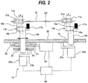
FIG. 2 is a side view of the substrate holding apparatus shown inFIG. 1 ; -
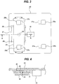
FIG. 3 is a bottom view of the substrate holding apparatus shown inFIG. 1 ; -
FIG. 4 is a cross-sectional view taken along line A-A ofFIG. 3 ; -
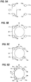
FIGS. 5A, 5B, 5C, 5D are schematic diagrams illustrating the operation of the substrate holding apparatus when receiving a wafer; -
FIG. 6 is a side view showing another embodiment of a substrate holding apparatus; -
FIG. 7 is a plan view of the substrate holding apparatus shown inFIG. 6 ; -
FIG. 8 is a bottom view of the substrate holding apparatus; -
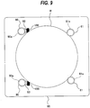
FIG. 9 is a plan view illustrating a state of the substrate holding apparatus when clamp rollers are away from a periphery of a wafer; -
FIG. 10 is a cross-sectional view taken along line B-B ofFIG. 6 ; -
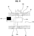
FIG. 11 is an enlarged view of one of four eccentric joints; -
FIG. 12 is a side view showing yet another embodiment of a substrate holding apparatus; -
FIG. 13 is an enlarged view of a first magnet gear shown inFIG. 12 ; -
FIG. 14A is a diagram showing a drive magnet rotor, andFIG. 14B is a diagram showing a driven magnet rotor; -
FIG. 15 is a plan view schematically showing an embodiment of a substrate processing apparatus including the substrate holding apparatus described with reference toFIGS. 1 through 5 ; and -
FIG. 16 is a side view of the substrate processing apparatus shown inFIG. 15 . - Embodiments will now be described with reference to the drawings.
FIG. 1 is a plan view schematically showing an embodiment of a substrate holding apparatus,FIG. 2 is a side view of the substrate holding apparatus shown inFIG. 1 , andFIG. 3 is a bottom view of the substrate holding apparatus shown inFIG. 1 . The substrate holding apparatus of this embodiment is configured to hold and rotate a wafer W which is an exemplary substrate. The substrate holding apparatus includes a plurality ofrollers 11a and a plurality ofrollers 11b, both of which are capable of contacting a periphery of the wafer W, aroller rotating mechanism 12 for rotating therollers eccentric shafts 13a coupling therollers 11a and theroller rotating mechanism 12 to each other, and a plurality ofeccentric shafts 13b coupling therollers 11b and theroller rotating mechanism 12 to each other. Eachroller 11a has a wafer holding surface (or a substrate holding surface) 31a for holding the periphery of the wafer W, and eachroller 11b has a wafer holding surface (or a substrate holding surface) 31b for holding the periphery of the wafer W. Eachroller 11a and eachroller 11b have the same construction and the same size. - The
eccentric shafts 13a each have afirst shaft portion 14a, and asecond shaft portion 15a which is eccentric relative to thefirst shaft portion 14a. Thefirst shaft portion 14a is secured to theroller rotating mechanism 12, and theroller 11a is secured to thesecond shaft portion 15a. Theeccentric shafts 13b each have afirst shaft portion 14b, and asecond shaft portion 15b which is eccentric relative to thefirst shaft portion 14b. Thefirst shaft portion 14b is secured to theroller rotating mechanism 12, and theroller 11b is secured to thesecond shaft portion 15b. - The
roller rotating mechanism 12 includes a plurality ofmotors 29a coupled respectively to thefirst shaft portions 14a of theeccentric shafts 13a, a plurality ofmotors 29b coupled respectively to thefirst shaft portions 14b of theeccentric shafts 13b, and anoperation controller 40 for causing themotors motor 29a is configured to rotate theeccentric shaft 13a about thefirst shaft portion 14a, and eachmotor 29b is configured to rotate theeccentric shaft 13b about thefirst shaft portion 14b. Themotors operation controller 40. - The operations of the
motors operation controller 40. More specifically, theoperation controller 40 starts and stops all themotors motors motors operation controller 40 synchronizes the rotational speeds and phases of themotors rollers - The substrate holding apparatus of this embodiment includes two
rollers 11a, tworollers 11b, twoeccentric shafts 13a, twoeccentric shafts 13b, twomotors 29a, and twomotors 29b. It is noted, however, that the numbers of these components are not limited to those of this embodiment. - The substrate holding apparatus further includes a
base plate 20. Theeccentric shafts base plate 20. Theroller rotating mechanism 12 is disposed at one side of thebase plate 20, and therollers base plate 20. - A plurality of linear motion guides 26 are secured to a lower surface of the
base plate 20, and amovable base 21 is supported by the linear motion guides 26. The linear motion guides 26 are coupled to themovable base 21. The linear motion guides 26 are configured to restrict movement of themovable base 21 to a linear movement in a direction parallel to the lower surface of thebase plate 20. Anactuator 18 is further secured to the lower surface of thebase plate 20. Themovable base 21 is coupled to theactuator 18. Theactuator 18 is disposed such that it moves themovable base 21 parallel to thebase plate 20. The operation of theactuator 18 is controlled by theoperation controller 40. The substrate holding apparatus further includes asupport plate 25 which rotatably supports the twoeccentric shafts 13b viabearings 24. The twomotors 29b are secured to thesupport plate 25 via motor supports 27b. -
FIG. 4 is a cross-sectional view taken along line A-A ofFIG. 3 . The substrate holding apparatus further includes apivot shaft 23 secured to thesupport plate 25. Thesupport plate 25 is disposed below themovable base 21, and thepivot shaft 23 is rotatably supported by abearing 28, which is fixed to themovable plate 21. Themovable base 21 and thesupport plate 25 are coupled together via thepivot shaft 23, and thesupport plate 25 is pivotable relative to themovable plate 21. The twoeccentric shafts 13b (seeFIG. 2 ), thesupport plate 25, and the twomotors 29b (seeFIG. 2 ) are configured to be capable of pivoting together on thepivot shaft 23. As shown by arrows inFIG. 2 , theactuator 18 moves the twoeccentric shafts 13b, thesupport plate 25, thepivot shaft 23, and the twomotors 29b, together with themovable base 21, parallel to thebase plate 20. - Referring back to
FIG. 2 ,bearings 19 are fixed to thebase plate 20. The twoeccentric shafts 13a are rotatably supported by thebase plate 20 via thebearings 19, respectively. The positions of theeccentric shafts 13a are fixed. The twomotors 29a are secured to thebase plate 20. More specifically, two motor supports 27a are secured to the lower surface of thebase plate 20, and the twomotors 29a are secured to the motor supports 27a, respectively. Thus, the twomotors 29a are secured to thebase plate 20 via the motor supports 27a. - According to the above-described construction, when the two
eccentric shafts 13b move in a direction closer to the twoeccentric shafts 13a, the wafer W is held by the tworollers 11a and the tworollers 11b. Since the tworollers 11b are pivotable on thepivot shaft 23, the positions of therollers 11b can be automatically adjusted when the fourrollers rollers 11a and the tworollers 11b when the twoeccentric shafts 13b move in a direction away from the twoeccentric shafts 13a. Though the twoeccentric shafts 13a and the twoeccentric shafts 13b, arranged around the axis CP of the substrate holding apparatus, are provided in this embodiment, the numbers of these components are not limited to those of this embodiment. For example, it is possible to provide oneeccentric shaft 13a and twoeccentric shafts 13b, arranged around the axis CP at equal intervals, i.e. 120-degree intervals. - The
second shaft portion 15a of eacheccentric shaft 13a is decentered by a distance e from thefirst shaft portion 14a. Accordingly, when themotor 29a is in motion, theroller 11a, while rotating about thesecond shaft portion 15a of theeccentric shaft 13a, makes a circular motion with a radius e. The axis of theroller 11a coincides with the axis of thesecond shaft portion 15a. Therefore, theroller 11a, while rotating about its axis, makes a circular motion with a radius e around the axis of thefirst shaft portion 14a. - Similarly, the
second shaft portion 15b of eacheccentric shaft 13b is decentered by a distance e from thefirst shaft portion 14b. Accordingly, when themotor 29b is in motion, theroller 11b, while rotating about thesecond shaft portion 15b of theeccentric shaft 13b, makes a circular motion with a radius e. The axis of theroller 11b coincides with the axis of thesecond shaft portion 15b. Therefore, theroller 11b, while rotating about its axis, makes a circular motion with a radius e around the axis of thefirst shaft portion 14b. The circular motion is defined herein as a movement of an object in a circular orbit. - As described above, the
operation controller 40 rotates all themotors operation controller 40 sets themotors rollers - In one embodiment, the
roller rotating mechanism 12 may include a plurality of driven pulleys (not shown) secured to thefirst shaft portions eccentric shafts rollers rollers - A
counter weight 17a and acounter weight 17b are secured to eacheccentric shaft 13a and eacheccentric shaft 13b, respectively. More specifically, thecounter weights intermediate shaft portions first shaft portions second shaft portions counter weight 17a and theroller 11a are arranged symmetrically with respect to thefirst shaft portion 14a. The weight of thecounter weight 17a is such that a centrifugal force, which is generated in the radial direction from thefirst shaft portion 14a toward theroller 11a when theeccentric shaft 13a is rotating about thefirst shaft portion 14a, is canceled by a centrifugal force acting on thecounter weight 17a. - Similarly, the
counter weight 17b and theroller 11b are arranged symmetrically with respect to thefirst shaft portion 14b. The weight of thecounter weight 17b is such that a centrifugal force, generated in the radial direction from thefirst shaft portion 14b toward theroller 11b when theeccentric shaft 13b is rotating about thefirst shaft portion 14b, is canceled by a centrifugal force acting on thecounter weight 17b.Such counter weights eccentric shafts eccentric shafts -
FIGS. 5A through 5D are schematic diagrams illustrating the operation of the substrate holding apparatus when receiving the wafer W. As shown inFIG. 5A , before the substrate holding apparatus receives the wafer W, the actuator 18 (seeFIG. 2 ) is set in motion to move therollers 11b in a direction away from therollers 11a. Therollers 11a and therollers 11b are decentered outward. As shown inFIG. 5B , the wafer W is transported to the substrate holding apparatus by a not-shown transport device. Thereafter, as shown inFIG. 5C , while the wafer W is located between therollers 11a and therollers 11b, theeccentric shafts 13a are rotated 180 degrees to decenter therollers 11a inward. Thereafter, theactuator 18 moves therollers 11b in a direction closer to therollers 11a until therollers 11b come into contact with the wafer W. The periphery of the wafer W is held by thewafer holding surfaces 31a of therollers 11a and the wafer holding surfaces 31b of therollers 11b. When the wafer W is to be removed from the substrate holding apparatus, the process steps shown inFIGS. 5A through 5D are performed in the opposite order. - The operation of the substrate holding apparatus, holding the wafer W, is as follows. The
operation controller 40 instructs themotors eccentric shafts first shaft portions operation controller 40 starts themotors operation controller 40 synchronizes the rotational speeds and the phases of all themotors - The substrate holding apparatus according to this embodiment has a simple construction and yet can rotate the wafer W about its axis while allowing the wafer W to make a circular motion. The combination of the circular motion of the wafer W and the rotation of the wafer W about the axis of the wafer W can increase the speed of the wafer W at any point on the surface of the wafer W. Therefore, when the below-described processing head is pressed against the surface of the wafer W, the relative speed between the processing head and the surface of the wafer W can be increased, thereby increasing a processing rate of the wafer W.
- Another embodiment will now be described.
FIG. 6 is a side view showing another embodiment of a substrate holding apparatus, andFIG. 7 is a plan view of the substrate holding apparatus shown inFIG. 6 . The substrate holding apparatus of this embodiment includes twodrive rollers 61 which are capable of contacting a periphery of a wafer W, twodrive shafts 64 to which the twodrive rollers 61 are secured respectively, an orbital table 66 which rotatably supports the twodrive shafts 64, abase plate 68 arranged away from the orbital table 66, twofirst motors 71 secured to thebase plate 68, and two firstuniversal joints 72 as first torque transmitting mechanisms coupling the twofirst motors 71 and the twodrive shafts 64, respectively. It is to be noted thatFIG. 6 only shows onedrive roller 61, onedrive shaft 64, onefirst motor 71, and one firstuniversal joint 72. - Though the substrate holding apparatus of this embodiment includes two
drive rollers 61, twodrive shafts 64, twofirst motors 71, and two firstuniversal joints 72, the numbers of these components are not limited to those of this embodiment. - Each
drive roller 61 has a wafer holding surface (or a substrate holding surface) 61a for holding the periphery of the wafer W. Eachdrive roller 61 is secured to one end of eachdrive shaft 64 so that thedrive roller 61 and thedrive shaft 64 can rotate together about the axis of thedrive roller 61. Thedrive shaft 64 extends perpendicularly to the orbital table 66. The orbital table 66 includes two bearings 75 (only onebearing 75 is shown inFIG. 6 ) that rotatably support the twodrive shafts 64, and apedestal 82 holding thesebearings 75. Thepedestal 82 of this embodiment has a plate-like shape, while there is no particular limitation on the shape of thepedestal 82 as long as a sufficient mechanical rigidity is ensured. Thedrive shafts 64 extend through the orbital table 66, and the other ends of thedrive shafts 64 are coupled to one ends of the firstuniversal joints 72, respectively. - In this embodiment, the
base plate 68 is located below the orbital table 66. The two firstuniversal joints 72 are arranged between the orbital table 66 and thebase plate 68. Each of the firstuniversal joints 72 is an articulated universal joint having a plurality of joints. One end of each firstuniversal joint 72 is coupled to thedrive shaft 64, while the other end of the firstuniversal joint 72 is coupled to theshaft 71a of thefirst motor 71. - The
first motors 71 are secured to thebase plate 68. More specifically,first motor platforms 85 are secured to the lower surface of thebase plate 68, and thefirst motors 71 are secured to thefirst motor platforms 85, respectively. Thus, thefirst motors 71 are secured to thebase plate 68 via thefirst motor platforms 85. Theshafts 71a of thefirst motors 71 are rotatably supported bybearings 86 fixed to thebase plate 68. Eachshaft 71a may be comprised of a plurality of shafts coupled in tandem by a coupling(s). - When the
first motor 71 is in operation, the rotation of theshaft 71a of thefirst motor 71 is transmitted through the first universal joint 72 to thedrive shaft 64, and thedrive shaft 64 and thedrive roller 61 rotate together about the axis of thedrive roller 61. - The substrate holding apparatus further includes two
clamp rollers 90 which are capable of contacting the periphery of the wafer W, twoeccentric shafts 93 which rotatably support the twoclamp rollers 90, tworotary actuators 96 secured to thebase plate 68, and two seconduniversal joints 98 as second torque transmitting mechanisms coupling the tworotary actuators 96 and the twoeccentric shafts 93, respectively. It is to be noted thatFIG. 6 only shows oneclamp roller 90, oneeccentric shaft 93, onerotary actuator 96, and one seconduniversal joint 98. - Though the substrate holding apparatus of this embodiment includes two
clamp rollers 90, twoeccentric shafts 93, tworotary actuators 96, and two seconduniversal joints 98, the numbers of these components are not limited to those of this embodiment. Though the twodrive shafts 64 and the twoeccentric shafts 93, arranged around the axis CP of the substrate holding apparatus, are provided in this embodiment, the numbers of these components are not limited to those of this embodiment. - Each
clamp roller 90 has a wafer holding surface (or a substrate holding surface) 90a for holding the periphery of the wafer W. Eacheccentric shaft 93 has afirst shaft portion 93a coupled to the seconduniversal joint 98, and asecond shaft portion 93b which is eccentric relative to thefirst shaft portion 93a. Acounter weight 100 is secured to each of theeccentric shafts 93. Thecounter weight 100 and theclamp roller 90 are arranged symmetrically with respect to thefirst shaft portion 93a. The weight of thecounter weight 100 is such that a centrifugal force, which acts on thesecond shaft portion 93b (or the clamp roller 90) by the below-described translational rotating motion, is canceled by a centrifugal force acting on thecounter weight 100. Thecounter weight 100 is provided to stabilize a clamping force of theclamp roller 90 applied to the wafer W during the below-described translational rotating motion, i.e. to prevent a clamping force of theclamp roller 90 applied to the wafer W from fluctuating due to the translational rotating motion. - The
clamp rollers 90 are rotatably coupled to thesecond shaft portions 93b, respectively. More specifically, each of thesecond shaft portions 93b has abearing 101 disposed therein, and eachclamp roller 90 is rotatably supported by thebearing 101. Such construction enables theclamp rollers 90 to rotate relative to theeccentric shafts 93. - The
eccentric shafts 93 are rotatably supported by the orbital table 66. More specifically, the orbital table 66 includes two bearings 104 (only onebearing 104 is shown inFIG. 6 ) held by thepedestal 82. Thefirst shaft portions 93a of the twoeccentric shafts 93 are rotatably supported by thebearings 104, respectively. The two seconduniversal joints 98 are located between the orbital table 66 and thebase plate 68. Each seconduniversal joint 98 is an articulated universal joint having a plurality of joints. One ends of the seconduniversal joints 98 are coupled to theeccentric shafts 93, while the other ends of the seconduniversal joints 98 are coupled to therotary actuators 96 secured to thebase plate 68. - Each of the
rotary actuators 96 includes anair cylinder 110, a crank 111 coupled to theair cylinder 110, and arotating shaft 112 secured to thecrank 111. Theair cylinder 110 is rotatably secured via apivot shaft 115 to the lower surface of thebase plate 68. Thepivot shaft 115 extends perpendicularly to thebase plate 68, and theair cylinder 110 can rotate about thepivot shaft 115 in a direction parallel to thebase plate 68. - The
rotating shaft 112 is rotatably supported by abearing 117 fixed to thebase plate 68. One end of therotating shaft 112 is secured to thecrank 111, while the other end of therotating shaft 112 is secured to the seconduniversal joint 98. Therotating shaft 112 may be comprised of a plurality of shafts coupled in tandem by a coupling(s). -
FIG. 8 is a bottom view of the substrate holding apparatus. Apiston rod 110a of theair cylinder 110 is rotatably coupled to an end portion of thecrank 111. The crank 111 converts a linear motion of thepiston rod 110a of theair cylinder 110 into a rotating motion. This rotating motion of thecrank 111 rotates therotating shaft 112. - When the
rotary actuator 96 is in motion, the second universal joint 98 (seeFIG. 6 ) rotates by a certain angle. This rotation of the seconduniversal joint 98 rotates the eccentric shaft 93 (seeFIG. 6 ) and, at the same time, causes the clamp roller 90 (seeFIG. 6 ) to make a circular motion. This circular motion of theclamp roller 90 is an arc-like movement of theclamp roller 90 around the axis of thefirst shaft portion 93a (seeFIG. 6 ) of theeccentric shaft 93. In particular, when therotary actuator 96 rotates theeccentric shaft 93 in one direction, theclamp roller 90 moves in a direction closer to the periphery of the wafer W. When therotary actuator 96 rotates theeccentric shaft 93 in the opposite direction, theclamp roller 90 moves in a direction away from the periphery of the wafer W. -
FIG. 7 illustrates a state of the substrate holding apparatus when theclamp rollers 90 have moved in a direction closer to the periphery of the wafer W, until thewafer holding surfaces 90a of theclamp rollers 90 are brought into contact with the periphery of the wafer W. As shown inFIG. 7 , when thewafer holding surfaces 90a of theclamp rollers 90 are brought into contact with the periphery of the wafer W, the wafer W is held by the twodrive rollers 61 and the twoclamp rollers 90. When thedrive rollers 61 rotate while the periphery of the wafer W is in contact with thedrive rollers 61 and theclamp rollers 90, the rotations of thedrive rollers 61 are transmitted to the wafer W, whereby the wafer W is rotated about the axis of the wafer W. - The positions of the
clamp rollers 90, shown inFIG. 7 , are clamping positions where theclamp rollers 90 hold the wafer W. When the rotary actuators 96 (seeFIGS. 6 and8 ) rotate theeccentric shafts 93 in the opposite direction, theclamp rollers 90 move away from the periphery of the wafer W.FIG. 9 illustrates a state of the substrate holding apparatus when theclamp rollers 90 are away from the periphery of the wafer W. The positions of theclamp rollers 90, shown inFIG. 9 , are unclamping positions where theclamp rollers 90 release the wafer W. - As shown in
FIG. 6 , the substrate holding apparatus further includes a translationalrotating mechanism 120 for causing the orbital table 66 to make a translational rotating motion. The translational rotating motion of the orbital table 66 is a circular motion of the orbital table 66 in a circular orbit without rotation of the orbital table 66 itself about the axis of the orbital table 66. This translational rotating motion is an example of a circular motion. The translationalrotating mechanism 120 includes a maineccentric shaft 121 rotatably coupled to the orbital table 66, asecond motor 124 coupled to the maineccentric shaft 121, and a plurality ofeccentric joints 128 coupling the orbital table 66 and thebase plate 68. - The main
eccentric shaft 121 includes a firstmain shaft portion 121a coupled to thesecond motor 124, and a secondmain shaft portion 121b rotatably coupled to the orbital table 66. The secondmain shaft portion 121b is decentered by a distance e from the firstmain shaft portion 121a. Abearing 125 is fixed to thebase plate 68, and the firstmain shaft portion 121a is rotatably supported by thebearing 125. The orbital table 66 has abearing 127 fixed to thepedestal 82, and the secondmain shaft portion 121b is rotatably supported by thebearing 127. - The
second motor 124 is secured to thebase plate 68. More specifically, asecond motor platform 129 is secured to the lower surface of thebase plate 68, and thesecond motor 124 is secured to thesecond motor platform 129. Thus, thesecond motor 124 is secured to thebase plate 68 via thesecond motor platform 129. When thesecond motor 124 is in motion, the maineccentric shaft 121 is rotated to cause the orbital table 66, coupled to the secondmain shaft portion 121b of the maineccentric shaft 121, to make a translational rotating motion. In one embodiment, thesecond motor 124 and the maineccentric shaft 121 may be coupled via a rotation transmitting mechanism (not shown) comprised of, for example, a combination of a belt and pulleys. - When the
second motor 124 rotates the maineccentric shaft 121, the orbital table 66 makes a translational rotating motion. Since thedrive shafts 64 and theeccentric shafts 93 are supported by the orbital table 66, thedrive rollers 61, theclamp rollers 90, thedrive shafts 64, theeccentric shafts 93, and the orbital table 66 make a translational rotating motion together. With the translational rotating motion of thedrive shafts 64 and theeccentric shafts 93, the wafer W held by thedrive rollers 61 and theclamp rollers 90 also makes a translational rotating motion. - The substrate holding apparatus further includes an
operation controller 134. Thefirst motors 71 and thesecond motor 124 are electrically connected to theoperation controller 134. Theoperation controller 134 is configured to be capable of controlling the operation of thefirst motors 71 and the operation of thesecond motor 124 independently. More specifically, theoperation controller 134 can independently control the start and stop of thefirst motors 71, the start and stop of thesecond motor 124, the rotational speed and the rotational direction of thefirst motors 71, and the rotational speed and the rotational direction of thesecond motor 124. For example, theoperation controller 134 can allow thefirst motors 71 and thesecond motor 124 to rotate at the same rotational speed or different rotational speeds. Further, theoperation controller 134 can allow thefirst motors 71 and thesecond motor 124 to rotate in the same rotational direction or different rotational directions. The above-described operation of therotary actuators 96 is also controlled by theoperation controller 134. - The
eccentric joints 128 function to keep the orbital table 66 parallel to thebase plate 68 while permitting the translational rotating motion of the orbital table 66. While only twoeccentric joints 128 are depicted inFIG. 6 , at least twoeccentric joints 128 are disposed around the maineccentric shaft 121. In this embodiment, foureccentric joints 128 are disposed around the maineccentric shaft 121, as shown inFIG. 10. FIG. 10 is a cross-sectional view taken along line B-B ofFIG. 6 . -
FIG. 11 is an enlarged view of one of the foureccentric joints 128. The othereccentric joints 128 have the same construction, and therefore a duplicate description thereof will be omitted. As shown inFIG. 11 , the eccentric joint 128 includes a firstjoint shaft portion 128a rotatably coupled to thebase plate 68, and a secondjoint shaft portion 128b rotatably coupled to the orbital table 66. Abearing 135 is fixed to thebase plate 68, and the firstjoint shaft portion 128a is rotatably supported by thebearing 135. The orbital table 66 has abearing 136 fixed to thepedestal 82, and the secondjoint shaft portion 128b is rotatably supported by thebearing 136. - The second
joint shaft portion 128b is decentered by a distance e from the firstjoint shaft portion 128a. This distance e is equal to the distance e by which the secondmain shaft portion 121b of the maineccentric shaft 121 is eccentric relative to the firstmain shaft portion 121a. Accordingly, when the orbital table 66 is making a translational rotating motion, the secondjoint shaft portion 128b of the eccentric joint 128 rotates in a circular orbit with the same radius as that of the circular orbit in which the secondmain shaft portion 121b of the maineccentric shaft 121 rotates. The thus-constructed eccentric joint 128 can support the orbital table 66 while allowing the orbital table 66 to make a translational rotating motion. - A
counter weight 140 is secured to theeccentric joint 128. Thecounter weight 140 is secured to anintermediate shaft portion 128c coupling the firstjoint shaft portion 128a and the secondjoint shaft portion 128b. Thecounter weight 140 and the secondjoint shaft portion 128b are arranged symmetrically with respect to the firstjoint shaft portion 128a. The weight of thecounter weight 140 is equal to an equally-divided amount of the sum of the weight of the orbital table 66 and the weight of structures, located above the orbital table 66, of the substrate holding apparatus. Specifically the weight of thecounter weight 140 is such that it can cancel a centrifugal force generated in the above structures, including the orbital table 66, by the translational rotating motion.Such counter weight 140 can prevent vibration of the above structures, including the orbital table 66, and vibration of the wafer W due to a weight imbalance during rotation of theeccentric joint 128. - The operation of the thus-constructed substrate holding apparatus is as follows. The two
rotary actuators 96 move theclamp rollers 90 to the unclamping positions shown inFIG. 9 . The wafer W is transported to the substrate holding apparatus by a not-shown transport device. While the wafer W is located between thedrive rollers 61 and theclamp rollers 90, therotary actuators 96 move theclamp rollers 90 to the clamping positions shown inFIG. 7 . The periphery of the wafer W is held by thewafer holding surfaces 61a of thedrive rollers 61 and thewafer holding surfaces 90a of theclamp rollers 90. - The
first motors 71 rotate thedrive rollers 61 about their own axes via the firstuniversal joints 72 and thedrive shafts 64. The rotations of thedrive rollers 61 are transmitted to the wafer W, whereby the wafer W rotates about the axis of the wafer W. Theclamp rollers 90 are freely rotatable. Therefore, theclamp rollers 90 are rotated by the rotation of the wafer W. Thesecond motor 124 of the translationalrotating mechanism 120 rotates the maineccentric shaft 121, thereby causing the orbital table 66 to make a translational rotating motion. The wafer W, thedrive rollers 61, theclamp rollers 90, thedrive shafts 64, and theeccentric shafts 93 make a translational rotating motion together with the orbital table 66. - As shown in
FIG. 6 , thedrive shafts 64 are coupled to thefirst motors 71 via the firstuniversal joints 72, and theeccentric shafts 93 are coupled to therotary actuators 96 via the seconduniversal joints 98. Therefore, thedrive shafts 64 and theeccentric shafts 93 can make a translational rotating motion together with the orbital table 66, while the positions of thefirst motors 71 and the positions of therotary actuators 96 are fixed. Thefirst motors 71 and therotary actuators 96, each of which have relatively heavy weight, are secured to thebase plate 68, and do not make a translational rotating motion. This configuration can stabilize the translational rotating motion of the orbital table 66, and can reduce the electrical power necessary for thesecond motor 124 to cause the orbital table 66 to make the translational rotating motion. Further, thefirst motors 71 and therotary actuators 96 are located below thebase plate 68. This arrangement eliminates the need for wiring and pipe connection to those portions which make a translational rotating motion, thus making it possible to avoid the risk of breaking of wire due to long-term operation. - The rotation of the
drive rollers 61 and the translational rotating motion of the orbital table 66 may be started simultaneously, or the rotation of thedrive rollers 61 may be started before or after the start of the translational rotating motion of the orbital table 66. The rotational speed of thedrive rollers 61 may be the same as or different from the rotational speed of the translational rotating motion of the orbital table 66. The start and stop of the rotation of thedrive rollers 61, the start and stop of the translational rotating motion of the orbital table 66, the rotational speed of thedrive rollers 61, and the rotational speed of the translational rotating motion of the orbital table 66 are controlled by theoperation controller 134. - The substrate holding apparatus according to this embodiment can rotate the wafer W about its own axis while causing the wafer W to make a translational rotating motion. The combination of the translational rotating motion of the wafer W and the rotation of the wafer W about its axis can increase the speed of the wafer W at any point on the surface of the wafer W. Therefore, when the below-described processing head is pressed against the surface of the wafer W, the relative speed between the processing head and the surface of the wafer W can be increased, thereby increasing a processing rate of the wafer W.
-
FIG. 12 is a side view showing yet another embodiment of a substrate holding apparatus. The construction and operation of this embodiment, not particularly described here, are the same as those of the embodiment described above with reference toFIGS. 6 through 11 , and therefore a duplicate description thereof will be omitted. - The substrate holding apparatus according to the embodiment shown in
FIG. 12 includes two first magnet gears 151 as first torque transmitting mechanisms, and two second magnet gears 152 as second torque transmitting mechanisms. The first magnet gears 151 and the second magnet gears 152 are located between the orbital table 66 and thebase plate 68. One ends of the first magnet gears 151 are coupled to thedrive shafts 64, while the other ends of the first magnet gears 151 are coupled to theshafts 71a of thefirst motors 71. One ends of the second magnet gears 152 are coupled to thefirst shaft portions 93a of theeccentric shafts 93, while the other ends of the second magnet gears 152 are coupled to therotating shafts 112 of therotary actuators 96. - Each
first magnet gear 151 and eachsecond magnet gear 152 have the same construction and the same size. Therefore, the construction of thefirst magnet gear 151 will be described below, and a description of thesecond magnet gear 152 will be omitted.FIG. 13 is an enlarged view of thefirst magnet gear 151. As shown inFIG. 13 , thefirst magnet gear 151 includes adrive magnet rotor 156, a drivenmagnet rotor 157, adrive coupling shaft 160 secured to the center of thedrive magnet rotor 156, and a drivencoupling shaft 161 secured to the center of the drivenmagnet rotor 157. Thedrive magnet rotor 156 and the drivenmagnet rotor 157 face each other with a slight gap between them. A diameter of thedrive magnet rotor 156 is larger than a diameter of the drivenmagnet rotor 157. The drivenmagnet rotor 157 is decentered by a distance e from thedrive magnet rotor 156. Thedrive coupling shaft 160 is coupled to theshaft 71a of thefirst motor 71, while the drivencoupling shaft 161 is coupled to thedrive shaft 64. -
FIG. 14A is a diagram showing thedrive magnet rotor 156, andFIG. 14B is a diagram showing the drivenmagnet rotor 157. Thedrive magnet rotor 156 has a plurality ofpermanent magnets 164 arranged in a circle. Similarly, the drivenmagnet rotor 157 has a plurality ofpermanent magnets 165 arranged in a circle. The torque of thedrive magnet rotor 156 is transmitted to the drivenmagnet rotor 157 by a magnetic force generated between thepermanent magnets 164 of thedrive magnet rotor 156 and thepermanent magnets 165 of the drivenmagnet rotor 157. - When the driven
magnet rotor 157 is making a translational rotating motion together with thedrive shaft 64, the drivenmagnet rotor 157, while keeping facing thedrive magnet rotor 156, makes a circular motion in a circumferential direction of thedrive magnet rotor 156. Therefore, the torque of thedrive magnet rotor 156 can be transmitted to the drivenmagnet rotor 157. -
FIG. 15 is a plan view schematically showing an embodiment of a substrate processing apparatus including the substrate holding apparatus described above with reference toFIGS. 1 through 5 , andFIG. 16 is a side view of the substrate processing apparatus shown inFIG. 15 . The construction and operation of this embodiment, not particularly described here, are the same as those of the embodiment described above with reference toFIGS. 1 through 5 , and therefore a duplicate description thereof will be omitted. The substrate processing apparatus of this embodiment includes asubstrate holding apparatus 10, and aprocessing head 200 for bringing aprocessing tool 201 into contact with afirst surface 1 of a wafer W, held by thesubstrate holding apparatus 10, to process thefirst surface 1. Theprocessing head 200 is located below the wafer W held by thesubstrate holding apparatus 10, and the position of theprocessing head 200 is fixed. - In this embodiment, the
first surface 1 of the wafer W is a back surface of the wafer W, i.e. a non-device surface where no device is formed or no device is to be formed. Asecond surface 2 of the wafer W, which is opposite from thefirst surface 1, is a front surface, i.e. a device surface where a device(s) is formed or a device(s) is to be formed. In this embodiment, the wafer W, with itsfirst surface 1 facing downward, is horizontally held by thesubstrate holding apparatus 10. - Detailed operation of the substrate processing apparatus of this embodiment is as follows. The
substrate holding apparatus 10 brings the plurality ofrollers 11a and the plurality ofrollers 11b into contact with the periphery of the wafer W, and rotates therollers rollers processing head 200 places theprocessing tool 201 in contact with thefirst surface 1 of the wafer W to process thefirst surface 1. - In this embodiment, the
processing tool 201 is longer than the radius of the wafer W. One end of theprocessing tool 201 protrudes outside the periphery of the wafer W, while the other end of theprocessing tool 201 extends across the axis CP of thesubstrate holding apparatus 10. Accordingly, theprocessing head 200 can bring theprocessing tool 201 into contact with the entirety of thefirst surface 1 of the rotating wafer W. This configuration enables theprocessing tool 201 to process the entirety of thefirst surface 1, including the outermost area, of the wafer W. Theprocessing head 200 is located in such a position as not to contact therollers eccentric shafts - The substrate holding apparatus according to this embodiment has a simple construction and yet can rotate the wafer W about its axis while allowing the wafer W to make a circular motion. The combination of the circular motion of the wafer W and the rotation of the wafer W about its axis can increase the speed of the wafer W at any point on the surface of the wafer W. Therefore, the relative speed between the
processing tool 201 and the surface of the wafer W can be increased, thereby increasing a processing rate of the wafer W. - In one embodiment, the
processing tool 201 may be a polishing tool for polishing the wafer W. Examples of the polishing tool include a polishing tape and a grindstone. In another embodiment, theprocessing tool 201 may be a cleaning tool for cleaning the wafer W. A cleaning tape is an example of the cleaning tool. A tape made of nonwoven fabric is an example of the cleaning tape. - In one embodiment, the substrate processing apparatus may include the substrate holding apparatus according to one of the embodiments described above with reference to
FIGS. 6 through 14 , instead of the substrate holding apparatus described above with reference toFIGS. 1 through 5 . The construction and operation of thesubstrate holding apparatus 10 are the same as those of one of the embodiments described above with reference toFIGS. 6 through 14 , and therefore a duplicate description thereof is omitted. - The previous description of embodiments is provided to enable a person skilled in the art to make and use the present invention. Moreover, various modifications to these embodiments will be readily apparent to those skilled in the art, and the generic principles and specific examples defined herein may be applied to other embodiments. Therefore, the present invention is not intended to be limited to the embodiments described herein but is to be accorded the widest scope as defined by limitation of the claims.
Claims (13)
- A substrate holding apparatus for holding a substrate and rotating the substrate, comprising:rollers capable of contacting a periphery of the substrate;a roller rotating mechanism configured to rotate the rollers; andeccentric shafts coupling the rollers and the roller rotating mechanism, the eccentric shafts having first shaft portions and second shaft portions, the second shaft portions being eccentric relative to the first shaft portions, the first shaft portions being secured to the roller rotating mechanism, and the rollers being secured to the second shaft portions, respectively.
- The substrate holding apparatus according to claim 1, wherein the roller rotating mechanism includes motors coupled to the first shaft portions, respectively, and an operation controller configured to rotate the motors at the same speed and in the same phase.
- The substrate holding apparatus according to claim 1 or 2, further comprising counter weights secured to the eccentric shafts, respectively, each of the counter weights and corresponding one of the rollers being arranged symmetrically with respect to corresponding one of the first shaft portions.
- A substrate processing apparatus comprising:the substrate holding apparatus according to any one of claims 1 to 3; anda processing head for bringing a processing tool into contact with a first surface of a substrate to process the first surface.
- A substrate holding apparatus for holding a substrate and rotating the substrate, comprising:a drive roller capable of contacting a periphery of the substrate;a drive shaft to which the drive roller is secured;an orbital table rotatably supporting the drive shaft;a base plate located away from the orbital table;a first motor secured to the base plate;a first torque transmitting mechanism coupling the first motor and the drive shaft; anda translational rotating mechanism configured to cause the orbital table to make a translational rotating motion.
- The substrate holding apparatus according to claim 5, further comprising:a clamp roller capable of contacting the periphery of the substrate;an eccentric shaft rotatably supporting the clamp roller, the eccentric shaft being rotatably supported by the orbital table;a rotary actuator secured to the base plate; anda second torque transmitting mechanism coupling the rotary actuator and the eccentric shaft.
- The substrate holding apparatus according to claim 6, further comprising a counter weight secured to the eccentric shaft,
wherein the eccentric shaft has a first shaft portion and a second shaft portion, the first shaft portion being coupled to the second torque transmitting mechanism, the second shaft portion being eccentric relative to the first shaft portion,
the clamp roller is rotatably coupled to the second shaft portion, and
the counter weight and the clamp roller are arranged symmetrically with respect to the first shaft portion. - The substrate holding apparatus according to any one of claims 5 to 7, further comprising an operation controller,
wherein the translational rotating mechanism includes a main eccentric shaft rotatably coupled to the orbital table, a second motor coupled to the main eccentric shaft, and eccentric joints coupling the orbital table and the base plate,
the second motor is secured to the base plate, and
the operation controller is configured to independently control a rotational speed of the first motor and a rotational speed of the second motor. - The substrate holding apparatus according to claim 8, wherein:the translational rotating mechanism has counter weights secured to the eccentric joints, respectively;each of the eccentric joints includes a first joint shaft portion rotatably coupled to the base plate, and a second joint shaft portion rotatably coupled to the orbital table;the second joint shaft portion is eccentric relative to the first joint shaft portion;the second joint shaft portion and corresponding one of the counter weights are arranged symmetrically with respect to the first joint shaft portion;the main eccentric shaft includes a first main shaft portion coupled to the second motor, and a second main shaft portion rotatably coupled to the orbital table; andthe second main shaft portion is eccentric relative to the first main shaft portion.
- The substrate holding apparatus according to any one of claims 5 to 9, wherein the first torque transmitting mechanism comprises a universal joint or a magnet gear.
- The substrate holding apparatus according to claim 6 or 7, wherein the second torque transmitting mechanism comprises a universal joint or a magnet gear.
- A substrate processing apparatus comprising:the substrate holding apparatus according to any one of claims 5 to 11; anda processing head for bringing a processing tool into contact with a first surface of a substrate to process the first surface.
- A substrate processing method comprising:bringing rollers into contact with a periphery of a substrate;rotating the rollers about their respective own axes while causing the rollers to make a circular motion, thereby rotating the substrate about an axis of the substrate and causing the substrate to make a circular motion; andbringing a processing tool into contact with the substrate, which is rotating and making the circular motion, to process the substrate.
Applications Claiming Priority (1)
| Application Number | Priority Date | Filing Date | Title |
|---|---|---|---|
| JP2017208327A JP6974116B2 (en) | 2017-10-27 | 2017-10-27 | A board processing device and a board processing method provided with a board holding device and a board holding device. |
Publications (2)
| Publication Number | Publication Date |
|---|---|
| EP3477393A1 true EP3477393A1 (en) | 2019-05-01 |
| EP3477393B1 EP3477393B1 (en) | 2026-01-07 |
Family
ID=63998513
Family Applications (1)
| Application Number | Title | Priority Date | Filing Date |
|---|---|---|---|
| EP18202401.8A Active EP3477393B1 (en) | 2017-10-27 | 2018-10-24 | Substrate holding apparatus, substrate processing apparatus and substrate processing method |
Country Status (6)
| Country | Link |
|---|---|
| US (2) | US12002704B2 (en) |
| EP (1) | EP3477393B1 (en) |
| JP (1) | JP6974116B2 (en) |
| KR (1) | KR102530553B1 (en) |
| CN (1) | CN109719103B (en) |
| TW (1) | TWI795450B (en) |
Cited By (1)
| Publication number | Priority date | Publication date | Assignee | Title |
|---|---|---|---|---|
| EP3753674A1 (en) * | 2019-06-18 | 2020-12-23 | Ebara Corporation | Substrate holding apparatus and substrate processing apparatus |
Families Citing this family (8)
| Publication number | Priority date | Publication date | Assignee | Title |
|---|---|---|---|---|
| WO2019173864A1 (en) * | 2018-03-15 | 2019-09-19 | Dalmac Enterprises Pty Ltd | Work supporting and rotating apparatus |
| JP7534084B2 (en) * | 2019-06-18 | 2024-08-14 | 株式会社荏原製作所 | Substrate holding device and substrate processing device |
| CN113838788B (en) * | 2020-06-24 | 2025-09-19 | 拓荆科技股份有限公司 | Automatic wafer bearing system and method for conveying wafers by adopting same |
| JP2023095345A (en) * | 2021-12-24 | 2023-07-06 | 株式会社荏原製作所 | Substrate processing method and substrate processing apparatus |
| JP7805203B2 (en) * | 2022-03-08 | 2026-01-23 | 株式会社東京精密 | Wafer rotation holding device |
| CN114653660B (en) * | 2022-05-20 | 2022-09-16 | 智程半导体设备科技(昆山)有限公司 | Magnetic clamping block and semiconductor substrate cleaning device |
| CN220372985U (en) * | 2023-07-10 | 2024-01-23 | 科达制造股份有限公司 | Grinding head supporting mechanism and grinding device thereof |
| CN117773754B (en) * | 2024-02-27 | 2024-04-26 | 扬中恒瑞金属制品有限公司 | Polishing machine tool for machining stainless steel well lid |
Citations (5)
| Publication number | Priority date | Publication date | Assignee | Title |
|---|---|---|---|---|
| US20030104698A1 (en) * | 2000-04-24 | 2003-06-05 | Toru Taniguchi | Method of manufacturing semiconductor wafer |
| US20070226992A1 (en) * | 2006-03-31 | 2007-10-04 | Hiroyuki Kaneko | Substrate holding rotating mechanism, and substrate processing apparatus |
| US20080017225A1 (en) * | 2006-07-24 | 2008-01-24 | Planar Semiconductor, Inc. | Holding and rotary driving mechanism for flat objects |
| US20080229526A1 (en) * | 2007-03-22 | 2008-09-25 | Taiwan Semiconductor Manufacturing Co., Ltd. | System for cleaning a wafer |
| US20130213437A1 (en) * | 2012-02-21 | 2013-08-22 | Kabushiki Kaisha Toshiba | Substrate processing apparatus and substrate processing method |
Family Cites Families (25)
| Publication number | Priority date | Publication date | Assignee | Title |
|---|---|---|---|---|
| US2614369A (en) * | 1947-07-26 | 1952-10-21 | Fast Inc Du | Sanding or rubbing attachment |
| US3978622A (en) * | 1975-07-23 | 1976-09-07 | Solid State Measurements, Inc. | Lapping and polishing apparatus |
| JPH0528760Y2 (en) * | 1985-09-18 | 1993-07-23 | ||
| JPH0528760A (en) | 1991-07-24 | 1993-02-05 | Nec Corp | Semiconductor memory |
| JPH06150305A (en) * | 1992-11-05 | 1994-05-31 | Fujitsu Ltd | Surface working method for magnetic disk substrate, magnetic disk substrate and surface working device for magnetic disk substrate |
| JPH0774133A (en) * | 1993-03-18 | 1995-03-17 | Dainippon Screen Mfg Co Ltd | Substrate processing equipment |
| US5566466A (en) * | 1994-07-01 | 1996-10-22 | Ontrak Systems, Inc. | Spindle assembly with improved wafer holder |
| JPH08125004A (en) * | 1994-10-27 | 1996-05-17 | Sony Corp | Wafer holder and wafer visual inspection apparatus using the same |
| US6413156B1 (en) | 1996-05-16 | 2002-07-02 | Ebara Corporation | Method and apparatus for polishing workpiece |
| JP3479430B2 (en) | 1997-05-23 | 2003-12-15 | 株式会社尼崎工作所 | Table rubbing exercise equipment |
| US5933902A (en) * | 1997-11-18 | 1999-08-10 | Frey; Bernhard M. | Wafer cleaning system |
| JP2000077379A (en) * | 1998-09-03 | 2000-03-14 | Toshiba Mach Co Ltd | Brush washing apparatus |
| US6616509B1 (en) * | 2000-03-31 | 2003-09-09 | Lam Research Corporation | Method for performing two wafer preparation operations on vertically oriented semiconductor wafer in single enclosure |
| WO2001074533A2 (en) | 2000-03-31 | 2001-10-11 | Lam Research Corporation | Methods for performing wafer preparation operations on vertically oriented semiconductor wafers |
| JP3494119B2 (en) * | 2000-04-24 | 2004-02-03 | 三菱住友シリコン株式会社 | Semiconductor wafer polishing method using a double-side polishing apparatus |
| JP4532014B2 (en) * | 2001-04-27 | 2010-08-25 | 芝浦メカトロニクス株式会社 | Spin processing equipment |
| JP2004342939A (en) * | 2003-05-16 | 2004-12-02 | Shimada Phys & Chem Ind Co Ltd | Substrate processing equipment |
| JP4343020B2 (en) | 2003-12-22 | 2009-10-14 | 株式会社住友金属ファインテック | Double-side polishing method and apparatus |
| JP4937807B2 (en) * | 2006-03-31 | 2012-05-23 | 株式会社荏原製作所 | Substrate holding and rotating mechanism, substrate processing apparatus |
| KR100746576B1 (en) | 2006-09-12 | 2007-08-06 | 세메스 주식회사 | Spin head and method for holding / unholding wafer using the same |
| JP6400977B2 (en) * | 2013-09-25 | 2018-10-03 | 芝浦メカトロニクス株式会社 | Spin processing device |
| JP6734666B2 (en) * | 2015-03-30 | 2020-08-05 | 芝浦メカトロニクス株式会社 | Spin processing device |
| KR102330017B1 (en) * | 2015-04-14 | 2021-11-24 | 가부시키가이샤 에바라 세이사꾸쇼 | Substrate processing apparatus and substrate processing method |
| JP6523991B2 (en) * | 2015-04-14 | 2019-06-05 | 株式会社荏原製作所 | Substrate processing apparatus and substrate processing method |
| JP6660202B2 (en) | 2016-02-19 | 2020-03-11 | 株式会社Screenホールディングス | Substrate processing apparatus and substrate processing method |
-
2017
- 2017-10-27 JP JP2017208327A patent/JP6974116B2/en active Active
-
2018
- 2018-10-19 TW TW107136859A patent/TWI795450B/en active
- 2018-10-23 US US16/168,301 patent/US12002704B2/en active Active
- 2018-10-23 KR KR1020180126510A patent/KR102530553B1/en active Active
- 2018-10-24 EP EP18202401.8A patent/EP3477393B1/en active Active
- 2018-10-25 CN CN201811250661.4A patent/CN109719103B/en active Active
-
2024
- 2024-04-30 US US18/650,935 patent/US12406874B2/en active Active
Patent Citations (6)
| Publication number | Priority date | Publication date | Assignee | Title |
|---|---|---|---|---|
| US20030104698A1 (en) * | 2000-04-24 | 2003-06-05 | Toru Taniguchi | Method of manufacturing semiconductor wafer |
| US20070226992A1 (en) * | 2006-03-31 | 2007-10-04 | Hiroyuki Kaneko | Substrate holding rotating mechanism, and substrate processing apparatus |
| US20080017225A1 (en) * | 2006-07-24 | 2008-01-24 | Planar Semiconductor, Inc. | Holding and rotary driving mechanism for flat objects |
| US20080229526A1 (en) * | 2007-03-22 | 2008-09-25 | Taiwan Semiconductor Manufacturing Co., Ltd. | System for cleaning a wafer |
| US20130213437A1 (en) * | 2012-02-21 | 2013-08-22 | Kabushiki Kaisha Toshiba | Substrate processing apparatus and substrate processing method |
| JP2013172019A (en) | 2012-02-21 | 2013-09-02 | Ebara Corp | Substrate processing apparatus and substrate processing method |
Cited By (2)
| Publication number | Priority date | Publication date | Assignee | Title |
|---|---|---|---|---|
| EP3753674A1 (en) * | 2019-06-18 | 2020-12-23 | Ebara Corporation | Substrate holding apparatus and substrate processing apparatus |
| US11335588B2 (en) | 2019-06-18 | 2022-05-17 | Ebara Corporation | Substrate holding apparatus and substrate processing apparatus |
Also Published As
| Publication number | Publication date |
|---|---|
| CN109719103B (en) | 2023-09-12 |
| TWI795450B (en) | 2023-03-11 |
| CN109719103A (en) | 2019-05-07 |
| US20190131166A1 (en) | 2019-05-02 |
| KR20190047611A (en) | 2019-05-08 |
| JP6974116B2 (en) | 2021-12-01 |
| KR102530553B1 (en) | 2023-05-10 |
| JP2019083224A (en) | 2019-05-30 |
| US12002704B2 (en) | 2024-06-04 |
| TW201923877A (en) | 2019-06-16 |
| US20240282619A1 (en) | 2024-08-22 |
| EP3477393B1 (en) | 2026-01-07 |
| US12406874B2 (en) | 2025-09-02 |
Similar Documents
| Publication | Publication Date | Title |
|---|---|---|
| US12406874B2 (en) | Substrate holding apparatus, substrate processing apparatus having substrate holding apparatus, and substrate processing method | |
| EP0940221B1 (en) | Polishing machine | |
| JP4256977B2 (en) | Double-side polishing system | |
| JP7341602B2 (en) | cutting equipment | |
| CN109397036B (en) | Method and apparatus for polishing a substrate, and method for processing a substrate | |
| JPH04135161A (en) | Polishing method and device thereof | |
| US6830505B2 (en) | Polishing machine | |
| TWI884961B (en) | Substrate holding apparatus and substrate processing apparatus | |
| JP2003503215A (en) | Method and apparatus for feeding a tool holder rotating about a rotationally symmetric structural part | |
| TW410187B (en) | Planetary gear system parallel planer | |
| JP2000190038A5 (en) | ||
| CN214454873U (en) | Workpiece reverse rotation transfer mechanism | |
| CN214444565U (en) | Rotating mechanism | |
| JP2009000783A (en) | Polishing and grinding device | |
| JP3285776B2 (en) | Crank pin phase indexing device | |
| JP2018023995A (en) | Bender for long object | |
| JP2005012081A (en) | Wafer gripping device and transfer device | |
| CN120395016B (en) | A burr removal device for planetary gear processing | |
| JPH08306759A (en) | Horizontal driver for transfer arm in wafer chamfering machine | |
| JP2002036099A (en) | Double-side polishing machine | |
| JP2000158261A (en) | Machining device | |
| JP3679941B2 (en) | Rotating body positioning device for centrifugal loading test apparatus and positioning method thereof | |
| JP2003080453A5 (en) | ||
| JPH10286763A (en) | Grinding device of substrate | |
| JPH1168394A5 (en) |
Legal Events
| Date | Code | Title | Description |
|---|---|---|---|
| PUAI | Public reference made under article 153(3) epc to a published international application that has entered the european phase |
Free format text: ORIGINAL CODE: 0009012 |
|
| STAA | Information on the status of an ep patent application or granted ep patent |
Free format text: STATUS: THE APPLICATION HAS BEEN PUBLISHED |
|
| AK | Designated contracting states |
Kind code of ref document: A1 Designated state(s): AL AT BE BG CH CY CZ DE DK EE ES FI FR GB GR HR HU IE IS IT LI LT LU LV MC MK MT NL NO PL PT RO RS SE SI SK SM TR |
|
| AX | Request for extension of the european patent |
Extension state: BA ME |
|
| STAA | Information on the status of an ep patent application or granted ep patent |
Free format text: STATUS: REQUEST FOR EXAMINATION WAS MADE |
|
| 17P | Request for examination filed |
Effective date: 20191104 |
|
| RBV | Designated contracting states (corrected) |
Designated state(s): AL AT BE BG CH CY CZ DE DK EE ES FI FR GB GR HR HU IE IS IT LI LT LU LV MC MK MT NL NO PL PT RO RS SE SI SK SM TR |
|
| STAA | Information on the status of an ep patent application or granted ep patent |
Free format text: STATUS: EXAMINATION IS IN PROGRESS |
|
| 17Q | First examination report despatched |
Effective date: 20211214 |
|
| RAP3 | Party data changed (applicant data changed or rights of an application transferred) |
Owner name: EBARA CORPORATION |
|
| GRAP | Despatch of communication of intention to grant a patent |
Free format text: ORIGINAL CODE: EPIDOSNIGR1 |
|
| STAA | Information on the status of an ep patent application or granted ep patent |
Free format text: STATUS: GRANT OF PATENT IS INTENDED |
|
| INTG | Intention to grant announced |
Effective date: 20250730 |
|
| GRAS | Grant fee paid |
Free format text: ORIGINAL CODE: EPIDOSNIGR3 |
|
| GRAA | (expected) grant |
Free format text: ORIGINAL CODE: 0009210 |
|
| STAA | Information on the status of an ep patent application or granted ep patent |
Free format text: STATUS: THE PATENT HAS BEEN GRANTED |
|
| AK | Designated contracting states |
Kind code of ref document: B1 Designated state(s): AL AT BE BG CH CY CZ DE DK EE ES FI FR GB GR HR HU IE IS IT LI LT LU LV MC MK MT NL NO PL PT RO RS SE SI SK SM TR |
|
| REG | Reference to a national code |
Ref country code: CH Ref legal event code: F10 Free format text: ST27 STATUS EVENT CODE: U-0-0-F10-F00 (AS PROVIDED BY THE NATIONAL OFFICE) Effective date: 20260107 Ref country code: GB Ref legal event code: FG4D |
|
| REG | Reference to a national code |
Ref country code: DE Ref legal event code: R096 Ref document number: 602018088411 Country of ref document: DE |
|
| REG | Reference to a national code |
Ref country code: IE Ref legal event code: FG4D |
|
| P01 | Opt-out of the competence of the unified patent court (upc) registered |
Free format text: CASE NUMBER: UPC_APP_0000814_3477393/2026 Effective date: 20260109 |