EP3477296B1 - Dual ultrasonic probe with variable roof angle - Google Patents
Dual ultrasonic probe with variable roof angle Download PDFInfo
- Publication number
- EP3477296B1 EP3477296B1 EP18199153.0A EP18199153A EP3477296B1 EP 3477296 B1 EP3477296 B1 EP 3477296B1 EP 18199153 A EP18199153 A EP 18199153A EP 3477296 B1 EP3477296 B1 EP 3477296B1
- Authority
- EP
- European Patent Office
- Prior art keywords
- transducer
- wedge
- probe
- dual probe
- assembly
- Prior art date
- Legal status (The legal status is an assumption and is not a legal conclusion. Google has not performed a legal analysis and makes no representation as to the accuracy of the status listed.)
- Active
Links
Images



Classifications
-
- G—PHYSICS
- G01—MEASURING; TESTING
- G01N—INVESTIGATING OR ANALYSING MATERIALS BY DETERMINING THEIR CHEMICAL OR PHYSICAL PROPERTIES
- G01N29/00—Investigating or analysing materials by the use of ultrasonic, sonic or infrasonic waves; Visualisation of the interior of objects by transmitting ultrasonic or sonic waves through the object
- G01N29/22—Details, e.g. general constructional or apparatus details
- G01N29/24—Probes
-
- G—PHYSICS
- G01—MEASURING; TESTING
- G01N—INVESTIGATING OR ANALYSING MATERIALS BY DETERMINING THEIR CHEMICAL OR PHYSICAL PROPERTIES
- G01N29/00—Investigating or analysing materials by the use of ultrasonic, sonic or infrasonic waves; Visualisation of the interior of objects by transmitting ultrasonic or sonic waves through the object
- G01N29/04—Analysing solids
- G01N29/043—Analysing solids in the interior, e.g. by shear waves
-
- G—PHYSICS
- G01—MEASURING; TESTING
- G01N—INVESTIGATING OR ANALYSING MATERIALS BY DETERMINING THEIR CHEMICAL OR PHYSICAL PROPERTIES
- G01N29/00—Investigating or analysing materials by the use of ultrasonic, sonic or infrasonic waves; Visualisation of the interior of objects by transmitting ultrasonic or sonic waves through the object
- G01N29/22—Details, e.g. general constructional or apparatus details
- G01N29/221—Arrangements for directing or focusing the acoustical waves
-
- G—PHYSICS
- G01—MEASURING; TESTING
- G01N—INVESTIGATING OR ANALYSING MATERIALS BY DETERMINING THEIR CHEMICAL OR PHYSICAL PROPERTIES
- G01N29/00—Investigating or analysing materials by the use of ultrasonic, sonic or infrasonic waves; Visualisation of the interior of objects by transmitting ultrasonic or sonic waves through the object
- G01N29/22—Details, e.g. general constructional or apparatus details
- G01N29/24—Probes
- G01N29/2487—Directing probes, e.g. angle probes
-
- G—PHYSICS
- G01—MEASURING; TESTING
- G01N—INVESTIGATING OR ANALYSING MATERIALS BY DETERMINING THEIR CHEMICAL OR PHYSICAL PROPERTIES
- G01N2291/00—Indexing codes associated with group G01N29/00
- G01N2291/04—Wave modes and trajectories
- G01N2291/044—Internal reflections (echoes), e.g. on walls or defects
-
- G—PHYSICS
- G01—MEASURING; TESTING
- G01N—INVESTIGATING OR ANALYSING MATERIALS BY DETERMINING THEIR CHEMICAL OR PHYSICAL PROPERTIES
- G01N2291/00—Indexing codes associated with group G01N29/00
- G01N2291/04—Wave modes and trajectories
- G01N2291/056—Angular incidence, angular propagation
-
- G—PHYSICS
- G01—MEASURING; TESTING
- G01N—INVESTIGATING OR ANALYSING MATERIALS BY DETERMINING THEIR CHEMICAL OR PHYSICAL PROPERTIES
- G01N2291/00—Indexing codes associated with group G01N29/00
- G01N2291/10—Number of transducers
- G01N2291/102—Number of transducers one emitter, one receiver
-
- G—PHYSICS
- G01—MEASURING; TESTING
- G01N—INVESTIGATING OR ANALYSING MATERIALS BY DETERMINING THEIR CHEMICAL OR PHYSICAL PROPERTIES
- G01N2291/00—Indexing codes associated with group G01N29/00
- G01N2291/10—Number of transducers
- G01N2291/105—Number of transducers two or more emitters, two or more receivers
Definitions
- the invention relates to ultrasonic non-destructive testing and inspection (NDT/NDI), and more particularly to an integrated dual probe with variable roof angle for pitch-catch inspection.
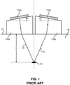
- Fig. 1 The principle of pitch-catch inspection is illustrated in Fig. 1 (prior art).
- Two probes 102a and 102b are each inclined at a roof angle ⁇ and are coupled to a test object 36 with wedges 106a and 106b respectively.
- Probes 102a and 102b are configured so that probe 102a is an emitting probe, emitting an ultrasonic beam 30 , and probe 102b is a receiving probe, receiving an ultrasonic echo beam 32 from a defect 34 at depth D below a test surface 37 of test object 36 .
- Probes 102a and 102b may be phased array probes in which case there may be multiple emitted and received ultrasonic beams, and the beams may be focused to have maximum sensitivity at or near the location of defect 34 at depth D .
- FIG. 1 illustrates a planar test surface 37
- test object 36 which is a pipe or other round or irregular surface.
- the bottom surfaces of wedges 106a and 106b would be customized to conform to test surface 37 .
- probes 102a and 102b and wedges 106a and 106b are separate assemblies.
- This arrangement has the disadvantage of large footprint: there are two separate probe housings and multiple cables.
- the size of the separate assemblies cannot be reduced sufficiently to allow pitch-catch inspection of small diameter tubes.
- integrated dual probe assemblies comprising both probes 102a and 102b in a single housing with fixed roof angle are known in the art.
- Such integrated probe assemblies are advantageous in that dual probes may be compactly packaged in a single housing with a single cable.
- a major disadvantage of integrated probe assemblies in existing practice is that they are costly and, since the roof angle is fixed, a different integrated probe assembly must be manufactured for each desired roof angle.
- United States Patent Application US 2008/010148856 A1 discloses a dual probe and wedge assembly with a mount, left and right transducers slidably attached to the mount for adjustment in axial and radial direction and left and right wedges with fixed roof angles.
- Fig. 2 is an isometric view of a dual probe and wedge assembly 1 comprising a dual probe assembly 2 attached to a wedge assembly 6 with screws 10a and 10b (not shown in Fig. 2 , see Figs. 5A and 5B ).
- Wedge assembly 6 comprises a left wedge 6a and a right wedge 6b , separated by an acoustic barrier 7 which prevents acoustic crosstalk between left wedge 6a and right wedge 6b .
- Dual probe assembly 2 comprises a left piezoelectric composite transducer 16a and a right piezoelectric composite transducer 16b (see Figs. 5A and 5B ) contained within a probe housing 12 .
- Cables for making electrical contact with elements of transducers 16a and 16b are preferably contained within a cable jacket 5 and a cable strain relief 4 .
- Couplant inlet/outlet manifolds 8a and 8b (not shown) provide a liquid couplant, preferably water, to facilitate acoustic coupling between dual probe and wedge assembly 1 and test surface 37 .
- Fig. 3 is a side section view of the left side of probe assembly 2 , and illustrates an important novel aspect of the present disclosure.
- a left side backing layer 14a and left piezoelectric composite transducer 16a are contained within a left frame 18a .
- Left transducer 16a has a left transducer contact surface 21a .
- Left frame 18a is pivotably supported by a rear left dowel pin 20a and a front left dowel pin 22a .
- Dowel pins 20a and 22a are preferably held in place by a rear left retaining clip 24a and a front left retaining clip 26a respectively.
- dowel pins 20a and 22a being substantially cylindrical in shape, allow frame 18a to rotate freely about an axis which is coaxial with the axes of dowel pins 20a and 22a .
- FIG. 3 Not shown in Fig. 3 are the equivalent features of the right side of probe assembly 2 .
- a right side backing layer 14b and right piezoelectric composite transducer 16b are contained within a right frame 18b .
- Right transducer 16b has a right transducer contact surface 21b.
- Right frame 18b is pivotably supported by a rear right dowel pin 20b and a front right dowel pin 22b.
- Dowel pins 20b and 22b are preferably held in place by a rear right retaining clip 24b and a front right retaining clip 26b respectively.
- Dowel pins 20b and 22b are substantially cylindrical in shape, and allow frame 18b to rotate freely about an axis which is coaxial with the axes of dowel pins 20b and 22b.
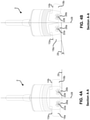
- Figs. 4A and 4B are sectional views of dual probe assembly 2 in the direction A-A as shown in Fig. 3 .
- Dual probe assembly 2 has a central plane of symmetry 28.
- frames 18a and 18b are shown rotated to a roof angle ⁇ of 0°. Roof angle ⁇ is measured relative to a perpendicular plane 29 , wherein perpendicular plane 29 is a plane perpendicular to central plane of symmetry 28.
- Fig. 4B frames 18a and 18b are shown rotated to a roof angle ⁇ of 10°. Note that most pitch-catch inspection applications require a roof angle of between 0° and 10°.
- probe assembly 2 may be configured so that screws 10a and 10b do not rotate, and all such configurations are within the scope of the present disclosure.
- dowel pins 22a and 20a (not shown) allow frame 18a to rotate freely, and dowel pins 22b and 20b (not shown) allow frame 18b to rotate freely.
- Figs. 5A and 5B are sectional views of dual probe and wedge assembly 1 in the direction B-B as shown in Fig. 3 .
- Figs. 5A and 5B illustrate how the roof angle is set by contact between dual probe assembly 2 and wedge assembly 6 .
- wedge assembly 6 comprises wedges 6a and 6b having upper wedge contact surfaces 17a and 17b defining a roof angle of 0°.
- a wedge assembly 6' comprises wedges 6a' and 6b' having upper wedge contact surfaces 17a' and 17b' defining a roof angle of 10°.
- upper wedge contact surfaces 17a and 17b have 0° inclination to perpendicular plane 29
- upper wedge contact surface 17a' has +10° inclination to perpendicular plane 29
- upper wedge contact surface 17b' has -10° inclination to perpendicular plane 29 .
- Wedges 6a and 6b have lower wedge surfaces 19a and 19b respectively, and wedges 6a' and 6b' have lower wedge surfaces 19a' and 19b' respectively.
- the lower wedge surfaces are configured to conform to test surface 37 of test object 36 .
- Lower wedge surfaces 19a' and 19b' may be the same as lower wedge surfaces 19a and 19b, in which case different roof angles of the same dual probe assembly may be used to inspect different depths of the same test object.
- lower wedge surfaces 19a' and 19b' may be different from lower wedge surfaces 19a and 19b , in which case different roof angles of the same dual probe assembly may be used for different test objects, for example pipes of different diameter.
- frames 18a and 18b are free to rotate about their respective dowel pins so that, in the absence of wedge assembly 6 , dual probe assembly 2 does not have a defined roof angle.
- Dual probe assembly 2 is capable of operating with any roof angle that the design allows, such as between 0° and 10°, and a specific roof angle is only defined when probe assembly 2 is attached to wedge assembly 6 , at which time the roof angle is defined by the inclination of upper wedge contact surfaces 17a and 17b.
- the pivot angle of transducer 16a is defined by the contact between left transducer contact surface 21a and upper wedge contact surface 17a
- the pivot angle of transducer 16b is defined by the contact between right transducer contact surface 21b and upper wedge contact surface 17b .
- the roof angles ⁇ are passively yet accurately set for each situation.
- an important novel aspect of the present disclosure is use of cylindrical dowel pins to pivotably attach transducers 16a and 16b to probe housing 12, thereby allowing rotational freedom, rather than fixing the transducers to the housing as in existing practice.
- pivotal joints there can be many ways of implementing pivotal joints to achieve this novel concept of rotational freedom, which are all taught and covered by the scope of this teaching.
- dowel pins may be used singly or in pairs, and other forms of pivotal joint attachment may be used to achieve the rotational freedom.
- Dual probe assembly 2 of the present disclosure allows increased flexibility and reduced cost compared with existing practice. Dual probe assembly 2 is much more expensive and much more difficult to manufacture than wedge assembly 6 .
- the dual probe assembly with variable roof angle of the present disclosure therefore allows a user to customize use of a single dual probe assembly for multiple inspection operations by manufacturing wedge assemblies configured for different depths and for differently shaped test objects.
Landscapes
- Physics & Mathematics (AREA)
- Health & Medical Sciences (AREA)
- Life Sciences & Earth Sciences (AREA)
- Chemical & Material Sciences (AREA)
- Analytical Chemistry (AREA)
- Biochemistry (AREA)
- General Health & Medical Sciences (AREA)
- General Physics & Mathematics (AREA)
- Immunology (AREA)
- Pathology (AREA)
- Acoustics & Sound (AREA)
- Investigating Or Analyzing Materials By The Use Of Ultrasonic Waves (AREA)
Description
- The invention relates to ultrasonic non-destructive testing and inspection (NDT/NDI), and more particularly to an integrated dual probe with variable roof angle for pitch-catch inspection.
- The principle of pitch-catch inspection is illustrated in
Fig. 1 (prior art). Twoprobes test object 36 withwedges probe 102a is an emitting probe, emitting anultrasonic beam 30, andprobe 102b is a receiving probe, receiving anultrasonic echo beam 32 from adefect 34 at depth D below atest surface 37 oftest object 36. Probes 102a and 102b may be phased array probes in which case there may be multiple emitted and received ultrasonic beams, and the beams may be focused to have maximum sensitivity at or near the location ofdefect 34 at depth D. - It should be noted that although
Fig. 1 illustrates aplanar test surface 37, the same principles apply for atest object 36 which is a pipe or other round or irregular surface. For inspecting atest object 36 having a round orirregular test surface 37, the bottom surfaces ofwedges test surface 37. - As illustrated in
Fig. 1 ,probes wedges - On the other hand, integrated dual probe assemblies comprising both
probes - United States Patent Application
US 2008/010148856 A1 - There therefore exists a need in the art for an integrated probe assembly in which the roof angle is variable over the entire range of desired roof angles.
- Accordingly, it is a general objective of the present disclosure to provide an integrated probe and wedge assembly having two probes configured so that the roof angle is fully adjustable over the entire range of useful roof angles.
- The objective is achieved by by a dual probe and wedge assembly as defined in
claim 1. -
-
Fig. 1 is a schematic illustration of the pitch-catch mode of defect detection. illustrating the existing practice. -
Fig. 2 is an isometric view of a dual probe assembly according to the present disclosure. -
Fig. 3 is an elevation section view of a dual probe assembly according to the present disclosure. -
Fig. 4A is a section view of a dual probe assembly according to the present disclosure, with probes configured at 0° roof angle. -
Fig. 4B is a section view of a dual probe assembly according to the present disclosure, with probes configured at 10° roof angle. -
Fig. 5A is a section view of a dual probe and wedge assembly according to the present disclosure, with probes configured at 0° roof angle. -
Fig. 5B is a section view of a dual probe and wedge assembly according to the present disclosure, with probes configured at 10° roof angle. -
Fig. 2 is an isometric view of a dual probe andwedge assembly 1 comprising adual probe assembly 2 attached to awedge assembly 6 withscrews Fig. 2 , seeFigs. 5A and 5B ).Wedge assembly 6 comprises aleft wedge 6a and aright wedge 6b, separated by anacoustic barrier 7 which prevents acoustic crosstalk betweenleft wedge 6a andright wedge 6b.Dual probe assembly 2 comprises a leftpiezoelectric composite transducer 16a and a rightpiezoelectric composite transducer 16b (seeFigs. 5A and 5B ) contained within aprobe housing 12. Cables for making electrical contact with elements oftransducers cable jacket 5 and acable strain relief 4. Couplant inlet/outlet manifolds 8a and 8b (not shown) provide a liquid couplant, preferably water, to facilitate acoustic coupling between dual probe andwedge assembly 1 andtest surface 37. -
Fig. 3 is a side section view of the left side ofprobe assembly 2, and illustrates an important novel aspect of the present disclosure. A leftside backing layer 14a and leftpiezoelectric composite transducer 16a are contained within aleft frame 18a.Left transducer 16a has a lefttransducer contact surface 21a.Left frame 18a is pivotably supported by a rearleft dowel pin 20a and a frontleft dowel pin 22a. Dowelpins clip 24a and a front left retainingclip 26a respectively. It should be noted that an important novel aspect of the present disclosure is thatdowel pins frame 18a to rotate freely about an axis which is coaxial with the axes ofdowel pins - Not shown in
Fig. 3 are the equivalent features of the right side ofprobe assembly 2. A rightside backing layer 14b and rightpiezoelectric composite transducer 16b are contained within aright frame 18b.Right transducer 16b has a right transducer contact surface 21b.Right frame 18b is pivotably supported by a rear right dowel pin 20b and a frontright dowel pin 22b. Dowelpins 20b and 22b are preferably held in place by a rear right retaining clip 24b and a frontright retaining clip 26b respectively.Dowel pins 20b and 22b are substantially cylindrical in shape, and allowframe 18b to rotate freely about an axis which is coaxial with the axes ofdowel pins 20b and 22b. -
Figs. 4A and 4B are sectional views ofdual probe assembly 2 in the direction A-A as shown inFig. 3 .Dual probe assembly 2 has a central plane ofsymmetry 28. InFig. 4A frames perpendicular plane 29, whereinperpendicular plane 29 is a plane perpendicular to central plane ofsymmetry 28. InFig. 4B ,frames screws frames screws frames probe assembly 2 may be configured so thatscrews - As can be seen in
Figs. 4A and 4B , dowel pins 22a and 20a (not shown) allowframe 18a to rotate freely, and dowel pins 22b and 20b (not shown) allowframe 18b to rotate freely. -
Figs. 5A and 5B are sectional views of dual probe andwedge assembly 1 in the direction B-B as shown inFig. 3 .Figs. 5A and 5B illustrate how the roof angle is set by contact betweendual probe assembly 2 andwedge assembly 6. InFig. 5A ,wedge assembly 6 compriseswedges Fig. 5B , a wedge assembly 6' compriseswedges 6a' and 6b' having upper wedge contact surfaces 17a' and 17b' defining a roof angle of 10°. Note that upper wedge contact surfaces 17a and 17b have 0° inclination toperpendicular plane 29, upperwedge contact surface 17a' has +10° inclination toperpendicular plane 29, and upperwedge contact surface 17b' has -10° inclination toperpendicular plane 29. -
Wedges lower wedge surfaces wedges 6a' and 6b' havelower wedge surfaces 19a' and 19b' respectively. The lower wedge surfaces are configured to conform to testsurface 37 oftest object 36.Lower wedge surfaces 19a' and 19b' may be the same aslower wedge surfaces lower wedge surfaces 19a' and 19b' may be different fromlower wedge surfaces - Referring to
Figs. 4A, 4B ,5A and 5B , an important aspect of the present disclosure is thatframes wedge assembly 6,dual probe assembly 2 does not have a defined roof angle.Dual probe assembly 2 is capable of operating with any roof angle that the design allows, such as between 0° and 10°, and a specific roof angle is only defined whenprobe assembly 2 is attached to wedgeassembly 6, at which time the roof angle is defined by the inclination of upper wedge contact surfaces 17a and 17b. The pivot angle oftransducer 16a is defined by the contact between lefttransducer contact surface 21a and upperwedge contact surface 17a, and the pivot angle oftransducer 16b is defined by the contact between right transducer contact surface 21b and upperwedge contact surface 17b. The roof angles φ are passively yet accurately set for each situation. - It should be noted that an important novel aspect of the present disclosure is use of cylindrical dowel pins to pivotably attach
transducers housing 12, thereby allowing rotational freedom, rather than fixing the transducers to the housing as in existing practice. There can be many ways of implementing pivotal joints to achieve this novel concept of rotational freedom, which are all taught and covered by the scope of this teaching. For example, dowel pins may be used singly or in pairs, and other forms of pivotal joint attachment may be used to achieve the rotational freedom. -
Dual probe assembly 2 of the present disclosure allows increased flexibility and reduced cost compared with existing practice.Dual probe assembly 2 is much more expensive and much more difficult to manufacture thanwedge assembly 6. The dual probe assembly with variable roof angle of the present disclosure therefore allows a user to customize use of a single dual probe assembly for multiple inspection operations by manufacturing wedge assemblies configured for different depths and for differently shaped test objects. - Although the present invention has been described in relation to particular embodiments thereof, it can be appreciated that various designs can be conceived based on the teachings of the present disclosure, and which are within the scope of the appended claims.
Claims (10)
- A dual probe and wedge assembly (6) comprising a dual probe assembly (2) attached to a wedge assembly,wherein the dual probe and wedge assembly has a central plane of symmetry, and,wherein the dual probe assembly comprises:a probe housing (12); at least one left pivotable joint member (20a, 22a);a left transducer (16a) pivotably attached to the probe housing by the at least one left pivotable joint member (20a, 22a), the left transducer having a left transducer contact surface;at least one right pivotable joint member (20b, 22b);and, a right transducer (16b) pivotably attached to the probe housing by the at least one right pivotable joint member (20b, 22b), the right transducer having a right transducer contact surface; and,wherein the left transducer is free to rotate about a left rotation axis and the right transducer is free to rotate about a right rotation axis; and,wherein the wedge assembly comprises:a left wedge (6a) having a left wedge contact surface (17a) inclined at a left roof angle to a perpendicular plane, wherein the perpendicular plane is perpendicular to the central plane of symmetry; and,a right wedge (6b) having a right wedge contact surface (17b) inclined at a right roof angle to the perpendicular plane; and, wherein the left transducer contact surface is in contact with the left wedge contact surface inclined at the left roof angle, and the right transducer contact surface is in contact with the right wedge contact surface inclined at the right roof angle.
- The dual probe and wedge assembly of claim 1, wherein the left transducer is an acoustic transducer and the right transducer is an acoustic transducer.
- The dual probe and wedge assembly of claim 2, wherein the left wedge and the right wedge are separated from each other by an acoustic barrier.
- The dual probe and wedge assembly of claim 1, wherein the at least one left pivotable joint member is a pair of left cylindrical pins, and wherein the at least one right pivotable joint member is a pair of right cylindrical pins.
- The dual probe and wedge assembly of claim 1, further comprising a left frame supporting the left transducer, and a right frame supporting the right transducer.
- The dual probe and wedge assembly of claim 5, wherein the left frame is pivotably attached to the probe housing by the at least one left pivotable joint member, and the right frame is pivotably attached to the probe housing by the at least one right pivotable joint member.
- The dual probe and wedge assembly of claim 5 or 6, wherein the left frame further contains a left side backing layer, and the right frame further contains a right side backing layer.
- The dual probe and wedge assembly of claim 1, further comprising a cable configured to make electrical connections to elements of the left transducer and the right transducer.
- The dual probe and wedge assembly of claim 8, wherein the housing further includes a cable hole for the cable to go through.
- The dual probe and wedge assembly of claim 1, wherein the both of the left rotation axis and the right rotation axis are parallel to the central plane of symmetry.
Applications Claiming Priority (1)
| Application Number | Priority Date | Filing Date | Title |
|---|---|---|---|
| US15/795,869 US11035829B2 (en) | 2017-10-27 | 2017-10-27 | Dual ultrasonic probe with variable roof angle |
Publications (2)
| Publication Number | Publication Date |
|---|---|
| EP3477296A1 EP3477296A1 (en) | 2019-05-01 |
| EP3477296B1 true EP3477296B1 (en) | 2022-02-16 |
Family
ID=63794396
Family Applications (1)
| Application Number | Title | Priority Date | Filing Date |
|---|---|---|---|
| EP18199153.0A Active EP3477296B1 (en) | 2017-10-27 | 2018-10-08 | Dual ultrasonic probe with variable roof angle |
Country Status (3)
| Country | Link |
|---|---|
| US (1) | US11035829B2 (en) |
| EP (1) | EP3477296B1 (en) |
| CN (1) | CN109725062B (en) |
Families Citing this family (16)
| Publication number | Priority date | Publication date | Assignee | Title |
|---|---|---|---|---|
| AT524895A1 (en) * | 2021-03-24 | 2022-10-15 | Ac2T Res Gmbh | Device for determining chemical-physical properties in a tribological system |
| US11673272B2 (en) | 2016-12-23 | 2023-06-13 | Gecko Robotics, Inc. | Inspection robot with stability assist device |
| EP3974823B1 (en) | 2016-12-23 | 2024-03-06 | Gecko Robotics, Inc. | Inspection robot |
| US12358141B2 (en) | 2016-12-23 | 2025-07-15 | Gecko Robotics, Inc. | Systems, methods, and apparatus for providing interactive inspection map for inspection robot |
| US12162160B2 (en) | 2016-12-23 | 2024-12-10 | Gecko Robotics, Inc. | System, apparatus and method for improved location identification with prism |
| US11035829B2 (en) | 2017-10-27 | 2021-06-15 | Olympus America Inc. | Dual ultrasonic probe with variable roof angle |
| US11549918B2 (en) * | 2017-10-27 | 2023-01-10 | Olympus America Inc. | Ultrasonic scanner with interchangeable wedge and flexible probe |
| GB201803062D0 (en) * | 2018-02-26 | 2018-04-11 | Gb Inspection Systems Ltd | Ultrasonic probe |
| US12531044B2 (en) * | 2021-01-22 | 2026-01-20 | The Boeing Company | Phased array ultrasonic testing device |
| WO2022159147A1 (en) | 2021-01-22 | 2022-07-28 | Ultratellege Usa Co., Limited | Dual ultrasonic catheter |
| US11865698B2 (en) | 2021-04-20 | 2024-01-09 | Gecko Robotics, Inc. | Inspection robot with removeable interface plates and method for configuring payload interfaces |
| WO2022226222A1 (en) | 2021-04-22 | 2022-10-27 | Gecko Robotics, Inc. | Systems, methods, and apparatus for ultra-sonic inspection of a surface |
| US12566158B2 (en) | 2021-04-22 | 2026-03-03 | Gecko Robotics, Inc. | Robotic systems for ultrasonic surface inspection using shaped elements |
| JP7023406B1 (en) | 2021-09-02 | 2022-02-21 | 三菱重工パワー検査株式会社 | Ultrasonic probe and ultrasonic flaw detection method |
| WO2024097795A2 (en) * | 2022-11-01 | 2024-05-10 | Gecko Robotics, Inc. | Inspection robot with profile adapting sled, couplant reduction film and transducer pod for thick assets |
| WO2024138219A2 (en) | 2022-12-23 | 2024-06-27 | Gecko Robotics, Inc. | Systems, methods, and apparatus for inspection of a surface using sensor holder with dual linear phased array of ultra-sonic elements |
Family Cites Families (22)
| Publication number | Priority date | Publication date | Assignee | Title |
|---|---|---|---|---|
| US3119102A (en) * | 1960-09-06 | 1964-01-21 | Ibm | Supporting means for transducer assemblies |
| GB1482077A (en) * | 1973-09-07 | 1977-08-03 | Videoson Ltd | Probes for ultrasonic waves |
| US4165649A (en) * | 1975-02-13 | 1979-08-28 | Southwest Research Institute | Apparatus and method for ultrasonic inspection of highly attenuative materials |
| US4454767A (en) * | 1980-03-25 | 1984-06-19 | Fuji Electric Co., Ltd. | Ultrasonic metering device |
| US5181421A (en) | 1988-01-22 | 1993-01-26 | Board Of Regents Of The University Of Oklahoma | Automatic monitoring of composite prepregs |
| US5421200A (en) * | 1993-08-26 | 1995-06-06 | General Electric Company | Ultrasonic fixture assembly for holding multiple ultrasonic transducers |
| US6247367B1 (en) | 1998-04-16 | 2001-06-19 | California Institute Of Technology | Multiplexed ultrasonic system |
| US6142008A (en) * | 1998-06-12 | 2000-11-07 | Abbott Laboratories | Air bubble sensor |
| US6578424B1 (en) * | 2000-09-27 | 2003-06-17 | Digital Wave Corporation | Hand-held variable angle membrane (VAM) ultrasonic scanning head for the noninvasive detection of corrosion, MIC and foreign objects in pipes |
| CA2449477A1 (en) * | 2003-11-14 | 2005-05-14 | Eric Lavoie | Development of the metar family of feeder inspection tools |
| US7484413B2 (en) | 2003-12-12 | 2009-02-03 | The Boeing Company | Remote radius inspection tool for composite joints |
| CN2874492Y (en) | 2006-03-29 | 2007-02-28 | 宝山钢铁股份有限公司 | Supersonic wave probe fixer for roller inner stress detection |
| US7669477B2 (en) | 2006-12-22 | 2010-03-02 | The Boeing Company | Ultrasonic probe for hollow fuse pin inspection |
| CN201653984U (en) | 2009-02-16 | 2010-11-24 | 江村 | Automatic continuous angle changing ultrasonic probe |
| EP2447714A1 (en) | 2010-10-28 | 2012-05-02 | Siemens Aktiengesellschaft | Automatic probe position-dependent angle of incidence adjustment for ultrasound probes |
| EP2568263B1 (en) * | 2011-09-12 | 2018-01-31 | Hydrosonic b.v. | Portable ultrasound flow measurement system |
| CN202256267U (en) | 2011-09-30 | 2012-05-30 | 武汉钢铁(集团)公司 | Adjustable ultrasonic testing probe box |
| WO2013086521A1 (en) | 2011-12-08 | 2013-06-13 | University Of Washington Through Its Center For Commercialization | Ultrasound stylet |
| KR20140115678A (en) | 2013-03-21 | 2014-10-01 | 알피니언메디칼시스템 주식회사 | Ultrasonic transducer |
| KR101480787B1 (en) | 2013-07-24 | 2015-01-13 | 성균관대학교산학협력단 | Apparatus for detecting surface defect having angle control function |
| US9746446B2 (en) | 2015-07-31 | 2017-08-29 | Olympus Scientific Solutions America Inc. | Probe holder providing constant lift-off for in-line bar-pipe testing |
| US11035829B2 (en) | 2017-10-27 | 2021-06-15 | Olympus America Inc. | Dual ultrasonic probe with variable roof angle |
-
2017
- 2017-10-27 US US15/795,869 patent/US11035829B2/en active Active
-
2018
- 2018-10-08 EP EP18199153.0A patent/EP3477296B1/en active Active
- 2018-10-18 CN CN201811216274.9A patent/CN109725062B/en active Active
Also Published As
| Publication number | Publication date |
|---|---|
| CN109725062A (en) | 2019-05-07 |
| CN109725062B (en) | 2022-07-08 |
| US20190128851A1 (en) | 2019-05-02 |
| US11035829B2 (en) | 2021-06-15 |
| EP3477296A1 (en) | 2019-05-01 |
Similar Documents
| Publication | Publication Date | Title |
|---|---|---|
| US11035829B2 (en) | Dual ultrasonic probe with variable roof angle | |
| US8286488B2 (en) | Apparatus and system for measuring material thickness | |
| US11733211B2 (en) | Method and device for testing a component non-destructively | |
| EP3759477B1 (en) | Time-of-flight diffraction transducer assembly and method for inspecting a test piece using said system | |
| CN110199194A (en) | Carry out the multicomponent method and device of detection part using ultrasonic wave | |
| US11841344B2 (en) | Ultrasonic dry coupled wheel probe with a radial transducer | |
| JP7284181B2 (en) | Phased array ultrasonic transducer device for non-destructive inspection of objects to be inspected | |
| US20160169840A1 (en) | Matrix phased array system for inspection of brazed welds | |
| EP2825876B1 (en) | Ultrasonic transducer array probe and method for fabricating such probe, method for controlling such probe and corresponding computer program | |
| JP2012256972A (en) | Ultrasonic sensor and manufacturing method of the same | |
| WO2014193556A1 (en) | Device for ultrasonic inspection | |
| US11835485B2 (en) | Ultrasonic probe having flexible stabilizing element for probe alignment | |
| US9116097B2 (en) | Part fixture for nondestructive inspection | |
| JP2015045536A (en) | Small-diameter pipe inspection device and inspection method for the same | |
| EP4402467A1 (en) | Enhanced coverage local immersion for non-destructive test (ndt) | |
| Rich et al. | Accuracy of a bistatic scattering substitution technique for calibration of focused receivers | |
| JP2023036092A (en) | Ultrasonic probe and method for ultrasonic flaw detection | |
| Alvarez-Arenas et al. | Air-coupled and water immersion sectorized array transducers for industrial and medical endoscopy | |
| WO2018147036A1 (en) | Ultrasound probe | |
| RU159204U1 (en) | ULTRASONIC IN-TUBE DEFECTOSCOPE BLOCK FOR IDENTIFICATION OF ARBITRALLY ORIENTED DEFECTS | |
| CN104990978A (en) | Ultrasonic transducer and pipe inside flow imaging device | |
| Glascock | Phased Arrays Improve Pipe Inspection | |
| JPH08160022A (en) | 2-element probe | |
| JPS60198454A (en) | Ultrasonic probe | |
| JPH09297125A (en) | Ultrasonic critical angle crack detecting device |
Legal Events
| Date | Code | Title | Description |
|---|---|---|---|
| PUAI | Public reference made under article 153(3) epc to a published international application that has entered the european phase |
Free format text: ORIGINAL CODE: 0009012 |
|
| STAA | Information on the status of an ep patent application or granted ep patent |
Free format text: STATUS: THE APPLICATION HAS BEEN PUBLISHED |
|
| AK | Designated contracting states |
Kind code of ref document: A1 Designated state(s): AL AT BE BG CH CY CZ DE DK EE ES FI FR GB GR HR HU IE IS IT LI LT LU LV MC MK MT NL NO PL PT RO RS SE SI SK SM TR |
|
| AX | Request for extension of the european patent |
Extension state: BA ME |
|
| STAA | Information on the status of an ep patent application or granted ep patent |
Free format text: STATUS: REQUEST FOR EXAMINATION WAS MADE |
|
| 17P | Request for examination filed |
Effective date: 20191104 |
|
| RBV | Designated contracting states (corrected) |
Designated state(s): AL AT BE BG CH CY CZ DE DK EE ES FI FR GB GR HR HU IE IS IT LI LT LU LV MC MK MT NL NO PL PT RO RS SE SI SK SM TR |
|
| GRAP | Despatch of communication of intention to grant a patent |
Free format text: ORIGINAL CODE: EPIDOSNIGR1 |
|
| STAA | Information on the status of an ep patent application or granted ep patent |
Free format text: STATUS: GRANT OF PATENT IS INTENDED |
|
| INTG | Intention to grant announced |
Effective date: 20210908 |
|
| GRAS | Grant fee paid |
Free format text: ORIGINAL CODE: EPIDOSNIGR3 |
|
| GRAA | (expected) grant |
Free format text: ORIGINAL CODE: 0009210 |
|
| STAA | Information on the status of an ep patent application or granted ep patent |
Free format text: STATUS: THE PATENT HAS BEEN GRANTED |
|
| AK | Designated contracting states |
Kind code of ref document: B1 Designated state(s): AL AT BE BG CH CY CZ DE DK EE ES FI FR GB GR HR HU IE IS IT LI LT LU LV MC MK MT NL NO PL PT RO RS SE SI SK SM TR |
|
| REG | Reference to a national code |
Ref country code: GB Ref legal event code: FG4D |
|
| REG | Reference to a national code |
Ref country code: CH Ref legal event code: EP |
|
| REG | Reference to a national code |
Ref country code: DE Ref legal event code: R096 Ref document number: 602018030849 Country of ref document: DE |
|
| REG | Reference to a national code |
Ref country code: AT Ref legal event code: REF Ref document number: 1469198 Country of ref document: AT Kind code of ref document: T Effective date: 20220315 |
|
| REG | Reference to a national code |
Ref country code: IE Ref legal event code: FG4D |
|
| REG | Reference to a national code |
Ref country code: DE Ref legal event code: R081 Ref document number: 602018030849 Country of ref document: DE Owner name: OLYMPUS SCIENTIFIC SOLUTIONS AMERICAS INC., WA, US Free format text: FORMER OWNER: OLYMPUS AMERICA INC., WALTHAM, MA, US |
|
| REG | Reference to a national code |
Ref country code: LT Ref legal event code: MG9D |
|
| REG | Reference to a national code |
Ref country code: NL Ref legal event code: MP Effective date: 20220216 |
|
| REG | Reference to a national code |
Ref country code: AT Ref legal event code: MK05 Ref document number: 1469198 Country of ref document: AT Kind code of ref document: T Effective date: 20220216 |
|
| PG25 | Lapsed in a contracting state [announced via postgrant information from national office to epo] |
Ref country code: SE Free format text: LAPSE BECAUSE OF FAILURE TO SUBMIT A TRANSLATION OF THE DESCRIPTION OR TO PAY THE FEE WITHIN THE PRESCRIBED TIME-LIMIT Effective date: 20220216 Ref country code: RS Free format text: LAPSE BECAUSE OF FAILURE TO SUBMIT A TRANSLATION OF THE DESCRIPTION OR TO PAY THE FEE WITHIN THE PRESCRIBED TIME-LIMIT Effective date: 20220216 Ref country code: PT Free format text: LAPSE BECAUSE OF FAILURE TO SUBMIT A TRANSLATION OF THE DESCRIPTION OR TO PAY THE FEE WITHIN THE PRESCRIBED TIME-LIMIT Effective date: 20220616 Ref country code: NO Free format text: LAPSE BECAUSE OF FAILURE TO SUBMIT A TRANSLATION OF THE DESCRIPTION OR TO PAY THE FEE WITHIN THE PRESCRIBED TIME-LIMIT Effective date: 20220516 Ref country code: NL Free format text: LAPSE BECAUSE OF FAILURE TO SUBMIT A TRANSLATION OF THE DESCRIPTION OR TO PAY THE FEE WITHIN THE PRESCRIBED TIME-LIMIT Effective date: 20220216 Ref country code: LT Free format text: LAPSE BECAUSE OF FAILURE TO SUBMIT A TRANSLATION OF THE DESCRIPTION OR TO PAY THE FEE WITHIN THE PRESCRIBED TIME-LIMIT Effective date: 20220216 Ref country code: HR Free format text: LAPSE BECAUSE OF FAILURE TO SUBMIT A TRANSLATION OF THE DESCRIPTION OR TO PAY THE FEE WITHIN THE PRESCRIBED TIME-LIMIT Effective date: 20220216 Ref country code: ES Free format text: LAPSE BECAUSE OF FAILURE TO SUBMIT A TRANSLATION OF THE DESCRIPTION OR TO PAY THE FEE WITHIN THE PRESCRIBED TIME-LIMIT Effective date: 20220216 Ref country code: BG Free format text: LAPSE BECAUSE OF FAILURE TO SUBMIT A TRANSLATION OF THE DESCRIPTION OR TO PAY THE FEE WITHIN THE PRESCRIBED TIME-LIMIT Effective date: 20220516 |
|
| PG25 | Lapsed in a contracting state [announced via postgrant information from national office to epo] |
Ref country code: PL Free format text: LAPSE BECAUSE OF FAILURE TO SUBMIT A TRANSLATION OF THE DESCRIPTION OR TO PAY THE FEE WITHIN THE PRESCRIBED TIME-LIMIT Effective date: 20220216 Ref country code: LV Free format text: LAPSE BECAUSE OF FAILURE TO SUBMIT A TRANSLATION OF THE DESCRIPTION OR TO PAY THE FEE WITHIN THE PRESCRIBED TIME-LIMIT Effective date: 20220216 Ref country code: GR Free format text: LAPSE BECAUSE OF FAILURE TO SUBMIT A TRANSLATION OF THE DESCRIPTION OR TO PAY THE FEE WITHIN THE PRESCRIBED TIME-LIMIT Effective date: 20220517 Ref country code: FI Free format text: LAPSE BECAUSE OF FAILURE TO SUBMIT A TRANSLATION OF THE DESCRIPTION OR TO PAY THE FEE WITHIN THE PRESCRIBED TIME-LIMIT Effective date: 20220216 Ref country code: AT Free format text: LAPSE BECAUSE OF FAILURE TO SUBMIT A TRANSLATION OF THE DESCRIPTION OR TO PAY THE FEE WITHIN THE PRESCRIBED TIME-LIMIT Effective date: 20220216 |
|
| PG25 | Lapsed in a contracting state [announced via postgrant information from national office to epo] |
Ref country code: IS Free format text: LAPSE BECAUSE OF FAILURE TO SUBMIT A TRANSLATION OF THE DESCRIPTION OR TO PAY THE FEE WITHIN THE PRESCRIBED TIME-LIMIT Effective date: 20220617 |
|
| PG25 | Lapsed in a contracting state [announced via postgrant information from national office to epo] |
Ref country code: SM Free format text: LAPSE BECAUSE OF FAILURE TO SUBMIT A TRANSLATION OF THE DESCRIPTION OR TO PAY THE FEE WITHIN THE PRESCRIBED TIME-LIMIT Effective date: 20220216 Ref country code: SK Free format text: LAPSE BECAUSE OF FAILURE TO SUBMIT A TRANSLATION OF THE DESCRIPTION OR TO PAY THE FEE WITHIN THE PRESCRIBED TIME-LIMIT Effective date: 20220216 Ref country code: RO Free format text: LAPSE BECAUSE OF FAILURE TO SUBMIT A TRANSLATION OF THE DESCRIPTION OR TO PAY THE FEE WITHIN THE PRESCRIBED TIME-LIMIT Effective date: 20220216 Ref country code: EE Free format text: LAPSE BECAUSE OF FAILURE TO SUBMIT A TRANSLATION OF THE DESCRIPTION OR TO PAY THE FEE WITHIN THE PRESCRIBED TIME-LIMIT Effective date: 20220216 Ref country code: DK Free format text: LAPSE BECAUSE OF FAILURE TO SUBMIT A TRANSLATION OF THE DESCRIPTION OR TO PAY THE FEE WITHIN THE PRESCRIBED TIME-LIMIT Effective date: 20220216 Ref country code: CZ Free format text: LAPSE BECAUSE OF FAILURE TO SUBMIT A TRANSLATION OF THE DESCRIPTION OR TO PAY THE FEE WITHIN THE PRESCRIBED TIME-LIMIT Effective date: 20220216 |
|
| REG | Reference to a national code |
Ref country code: DE Ref legal event code: R097 Ref document number: 602018030849 Country of ref document: DE |
|
| PG25 | Lapsed in a contracting state [announced via postgrant information from national office to epo] |
Ref country code: AL Free format text: LAPSE BECAUSE OF FAILURE TO SUBMIT A TRANSLATION OF THE DESCRIPTION OR TO PAY THE FEE WITHIN THE PRESCRIBED TIME-LIMIT Effective date: 20220216 |
|
| PLBE | No opposition filed within time limit |
Free format text: ORIGINAL CODE: 0009261 |
|
| STAA | Information on the status of an ep patent application or granted ep patent |
Free format text: STATUS: NO OPPOSITION FILED WITHIN TIME LIMIT |
|
| 26N | No opposition filed |
Effective date: 20221117 |
|
| PG25 | Lapsed in a contracting state [announced via postgrant information from national office to epo] |
Ref country code: SI Free format text: LAPSE BECAUSE OF FAILURE TO SUBMIT A TRANSLATION OF THE DESCRIPTION OR TO PAY THE FEE WITHIN THE PRESCRIBED TIME-LIMIT Effective date: 20220216 |
|
| PG25 | Lapsed in a contracting state [announced via postgrant information from national office to epo] |
Ref country code: MC Free format text: LAPSE BECAUSE OF FAILURE TO SUBMIT A TRANSLATION OF THE DESCRIPTION OR TO PAY THE FEE WITHIN THE PRESCRIBED TIME-LIMIT Effective date: 20220216 |
|
| REG | Reference to a national code |
Ref country code: CH Ref legal event code: PL |
|
| REG | Reference to a national code |
Ref country code: BE Ref legal event code: MM Effective date: 20221031 |
|
| PG25 | Lapsed in a contracting state [announced via postgrant information from national office to epo] |
Ref country code: LU Free format text: LAPSE BECAUSE OF NON-PAYMENT OF DUE FEES Effective date: 20221008 |
|
| PG25 | Lapsed in a contracting state [announced via postgrant information from national office to epo] |
Ref country code: LI Free format text: LAPSE BECAUSE OF NON-PAYMENT OF DUE FEES Effective date: 20221031 Ref country code: IT Free format text: LAPSE BECAUSE OF FAILURE TO SUBMIT A TRANSLATION OF THE DESCRIPTION OR TO PAY THE FEE WITHIN THE PRESCRIBED TIME-LIMIT Effective date: 20220216 Ref country code: CH Free format text: LAPSE BECAUSE OF NON-PAYMENT OF DUE FEES Effective date: 20221031 |
|
| PG25 | Lapsed in a contracting state [announced via postgrant information from national office to epo] |
Ref country code: BE Free format text: LAPSE BECAUSE OF NON-PAYMENT OF DUE FEES Effective date: 20221031 |
|
| PG25 | Lapsed in a contracting state [announced via postgrant information from national office to epo] |
Ref country code: IE Free format text: LAPSE BECAUSE OF NON-PAYMENT OF DUE FEES Effective date: 20221008 |
|
| PG25 | Lapsed in a contracting state [announced via postgrant information from national office to epo] |
Ref country code: HU Free format text: LAPSE BECAUSE OF FAILURE TO SUBMIT A TRANSLATION OF THE DESCRIPTION OR TO PAY THE FEE WITHIN THE PRESCRIBED TIME-LIMIT; INVALID AB INITIO Effective date: 20181008 |
|
| PG25 | Lapsed in a contracting state [announced via postgrant information from national office to epo] |
Ref country code: CY Free format text: LAPSE BECAUSE OF FAILURE TO SUBMIT A TRANSLATION OF THE DESCRIPTION OR TO PAY THE FEE WITHIN THE PRESCRIBED TIME-LIMIT Effective date: 20220216 |
|
| PG25 | Lapsed in a contracting state [announced via postgrant information from national office to epo] |
Ref country code: MK Free format text: LAPSE BECAUSE OF FAILURE TO SUBMIT A TRANSLATION OF THE DESCRIPTION OR TO PAY THE FEE WITHIN THE PRESCRIBED TIME-LIMIT Effective date: 20220216 |
|
| PG25 | Lapsed in a contracting state [announced via postgrant information from national office to epo] |
Ref country code: TR Free format text: LAPSE BECAUSE OF FAILURE TO SUBMIT A TRANSLATION OF THE DESCRIPTION OR TO PAY THE FEE WITHIN THE PRESCRIBED TIME-LIMIT Effective date: 20220216 |
|
| PG25 | Lapsed in a contracting state [announced via postgrant information from national office to epo] |
Ref country code: MT Free format text: LAPSE BECAUSE OF FAILURE TO SUBMIT A TRANSLATION OF THE DESCRIPTION OR TO PAY THE FEE WITHIN THE PRESCRIBED TIME-LIMIT Effective date: 20220216 |
|
| REG | Reference to a national code |
Ref country code: GB Ref legal event code: 732E Free format text: REGISTERED BETWEEN 20250925 AND 20251001 |
|
| REG | Reference to a national code |
Ref country code: GB Ref legal event code: 732E Free format text: REGISTERED BETWEEN 20251016 AND 20251022 |
|
| PGFP | Annual fee paid to national office [announced via postgrant information from national office to epo] |
Ref country code: DE Payment date: 20251029 Year of fee payment: 8 |
|
| PGFP | Annual fee paid to national office [announced via postgrant information from national office to epo] |
Ref country code: GB Payment date: 20251027 Year of fee payment: 8 |
|
| PGFP | Annual fee paid to national office [announced via postgrant information from national office to epo] |
Ref country code: FR Payment date: 20251027 Year of fee payment: 8 |