EP3477125A1 - Expansion anchor with sleeve abutment walls - Google Patents
Expansion anchor with sleeve abutment walls Download PDFInfo
- Publication number
- EP3477125A1 EP3477125A1 EP17198246.5A EP17198246A EP3477125A1 EP 3477125 A1 EP3477125 A1 EP 3477125A1 EP 17198246 A EP17198246 A EP 17198246A EP 3477125 A1 EP3477125 A1 EP 3477125A1
- Authority
- EP
- European Patent Office
- Prior art keywords
- expansion
- expansion sleeve
- abutment wall
- anchor
- sleeve
- Prior art date
- Legal status (The legal status is an assumption and is not a legal conclusion. Google has not performed a legal analysis and makes no representation as to the accuracy of the status listed.)
- Withdrawn
Links
- 238000000034 method Methods 0.000 claims abstract description 11
- 230000007704 transition Effects 0.000 claims description 15
- 239000000758 substrate Substances 0.000 description 13
- 238000004519 manufacturing process Methods 0.000 description 7
- 238000009434 installation Methods 0.000 description 6
- 230000007246 mechanism Effects 0.000 description 6
- 238000006073 displacement reaction Methods 0.000 description 4
- 230000004913 activation Effects 0.000 description 2
- 230000004323 axial length Effects 0.000 description 2
- 230000008859 change Effects 0.000 description 2
- 230000000694 effects Effects 0.000 description 2
- 230000002028 premature Effects 0.000 description 2
- 229910000975 Carbon steel Inorganic materials 0.000 description 1
- 229910000831 Steel Inorganic materials 0.000 description 1
- 239000010962 carbon steel Substances 0.000 description 1
- 125000004122 cyclic group Chemical group 0.000 description 1
- 230000007423 decrease Effects 0.000 description 1
- 230000001419 dependent effect Effects 0.000 description 1
- 238000009826 distribution Methods 0.000 description 1
- 230000006872 improvement Effects 0.000 description 1
- 239000000463 material Substances 0.000 description 1
- 238000005096 rolling process Methods 0.000 description 1
- 239000010935 stainless steel Substances 0.000 description 1
- 229910001220 stainless steel Inorganic materials 0.000 description 1
- 239000010959 steel Substances 0.000 description 1
Images


Classifications
-
- F—MECHANICAL ENGINEERING; LIGHTING; HEATING; WEAPONS; BLASTING
- F16—ENGINEERING ELEMENTS AND UNITS; GENERAL MEASURES FOR PRODUCING AND MAINTAINING EFFECTIVE FUNCTIONING OF MACHINES OR INSTALLATIONS; THERMAL INSULATION IN GENERAL
- F16B—DEVICES FOR FASTENING OR SECURING CONSTRUCTIONAL ELEMENTS OR MACHINE PARTS TOGETHER, e.g. NAILS, BOLTS, CIRCLIPS, CLAMPS, CLIPS OR WEDGES; JOINTS OR JOINTING
- F16B13/00—Dowels or other devices fastened in walls or the like by inserting them in holes made therein for that purpose
- F16B13/04—Dowels or other devices fastened in walls or the like by inserting them in holes made therein for that purpose with parts gripping in the hole or behind the reverse side of the wall after inserting from the front
- F16B13/06—Dowels or other devices fastened in walls or the like by inserting them in holes made therein for that purpose with parts gripping in the hole or behind the reverse side of the wall after inserting from the front combined with expanding sleeve
- F16B13/063—Dowels or other devices fastened in walls or the like by inserting them in holes made therein for that purpose with parts gripping in the hole or behind the reverse side of the wall after inserting from the front combined with expanding sleeve by the use of an expander
- F16B13/065—Dowels or other devices fastened in walls or the like by inserting them in holes made therein for that purpose with parts gripping in the hole or behind the reverse side of the wall after inserting from the front combined with expanding sleeve by the use of an expander fastened by extracting the screw, nail or the like
Definitions
- the invention relates to an expansion anchor according to the preamble of claim 1.
- Such an anchor is provided with an anchor bolt, an expansion sleeve surrounding the anchor bolt, and an expansion body located in a front region of the anchor bolt, wherein the expansion body has a converging zone for expanding the expansion sleeve.
- WO 15067578 A1 describes an expansion anchor having grooves that are closed with respect to the front end of the anchor disposed in the expansion body, wherein the grooves reduce a contact surface between the expansion sleeve and the oblique surface of the expansion body.
- the individual grooves are relatively narrow to avoid the expansion sleeve being bent into the grooves when the expansion sleeve is expanded.
- EP2848825 A1 discloses an expansion anchor in which the expansion sleeve has at least one web on its inner side, which web engages a groove in the anchor bolt. During installation, this web is displaced radially outwardly by the expansion body of the bolt.
- EP2514979 A1 shows an anchor bolt with an eccentric region that widens the expansion sleeve upon rotation of the anchor bolt.
- EP2309138 A2 shows an expansion body having longitudinal edges.
- DE2256822 A1 discloses an expansion anchor, in which a rotation lock is provided between the expansion sleeve and the anchor bolt.
- This rotation lock might be formed by a groove extending into the expansion body of the bolt, and a corrsponding protrusion, which protrudes from the expansion sleeve.
- the groove extends axially all along the expansion body and the protrusion extends axially all along the expansion sleeve.
- the protrusion is shorter and offset from the expansion sleeve tip towards the rear end of the expansion sleeve.
- WO12126700 A1 describes expansion anchors having webs on their expansion bodies, which webs can act upon the inside of the expansion sleeves of the anchors.
- EP 0515916 A2 and DE3411285 A1 describe fasteners. In both cases, sleeves interlock with inner bolts via toothings.
- An inventive anchor is characterized in that the expansion body has at least one expansion sleeve abutment wall facing the expansion sleeve.
- a first basic idea of the present invention may be seen in providing the expansion body with at least one expansion sleeve abutment wall, which expansion sleeve abutment wall faces the expansion sleeve before installation of the anchor, so that the expansion sleeve can hit the expansion sleeve abutment wall when the expansion body moves along the expansion sleeve during expansion of the expansion sleeve, when the anchor is installed. It has been unexpectedly discovered that this can significantly improve anchor performance. The following mechanism can explain the observed improvement: When the tip of the expansion sleeve touches the expansion sleeve abutment wall, a kind of temporary form fit can be generated between the expansion sleeve and the expansion body.
- This form fit can increase the resistance against pull-out of the expansion body out of the expansion sleeve, but it can do so advantageously without significant additional expansion of the expansion sleeve, i.e. without increasing the expansion force significantly. Due to the low expansion force, the substrate that surrounds the anchor, e.g. concrete, will not be overstressed, whereas the pullout loads remarkably increase. Thus, due to the interlock between expansion sleeve abutment wall and expansion sleeve, concrete capacity can increase significantly above the level of standard expansion anchors.
- the interlock between expansion sleeve abutment wall and expansion sleeve can reduce relative movement between expansion sleeve and expansion body plus anchor bolt, the total anchor displacement behavior, in particular in cyclic load cracked concrete conditions can also be improved.
- the anchor bolt is an elongate body.
- the expansion body and the anchor bolt are, in particular, connected to transfer tensile forces.
- the expansion body can for example be threaded to the anchor bolt, in particular if the expansion anchor is a so-called sleeve-type expansion anchor.
- the expansion body can also be tightly fixed to the anchor bolt, in particular if the expansion anchor is a so-called stud-type expansion anchor. It is particularly preferred in case of a stud-type expansion anchor that the expansion body and the anchor bolt are integral, i.e. that they form one piece.
- the anchor bolt is preferably provided with a forwardly-facing shoulder for expansion sleeve abutment and for advancing the expansion sleeve into the borehole.
- the expansion body is a part of the expansion anchor.
- the expansions sleeve surrounds the anchor bolt, in particular around the longitudinal axis.
- the expansion sleeve is a single piece. However, it could also consist of several individual segments, which are for example held in a bolt-surrounding arrangement by means of a rubber band or by snap-on mechanisms.
- the anchor bolt, the expansion sleeve and/or the expansion body are each steel parts. They can for example comprise carbon steel or stainless steel.
- the anchor bolt can have, in a rear region of the anchor bolt, a tension-introducing structure.
- the tension-introducing structure is for introducing tensile force into the anchor bolt.
- the tension-introducing structure can for example be a thread, in particular an outer thread, provided on the anchor bolt.
- the tension-introducing structure can for example also be a head, that forms a maximum cross-section, or a bayonet-type lock.
- the converging zone of the expansion body serves to expand the expansion sleeve when the expansion sleeve is moved forward with respect to the expansion body, in particular to expand the expansion sleeve radially with respect to the longitudinal axis.
- the expansion body converges, on its lateral surface, towards the rear of the anchor bolt and/or towards the tension-introducing structure, wherein the focus of convergence can preferably be the longitudinal axis. This in particular implies that the radial distance of the lateral surface of the expansion body from the longitudinal axis becomes smaller towards the rear of the expansion body.
- the expansion body can have additional zones, for example a preferably cylindrical transition zone and/or a tip zone.
- the converging zone can for example be conical, or can have a more complex, for example a convex or concave shape. In particular, the converging zone forms a wedge for the expansion sleeve.
- the expansion sleeve abutment wall is for creating an interlock between the expansion body and the expansion sleeve.
- the expansion sleeve abutment wall is so arranged that the expansion sleeve can hit the expansion sleeve abutment wall, i.e. that the expansion sleeve can abut on the expansion sleeve abutment wall, when the expansion sleeve is axially displaced relative to the expansion body in the forwards direction, i.e. towards the front end of the expansion body and/or the anchor bolt, in particular by drawing-in the expansion body into the expansion sleeve in the rearwards direction.
- the expansion sleeve abutment wall axially faces the expansion sleeve, or, in other words, the expansion sleeve abutment wall faces the expansion sleeve in a direction parallel to the longitudinal axis.
- the expansion sleeve abutment wall faces, in particular axially faces, the tip of the expansion sleeve and/or serves for abutment of the tip of the expansion sleeve, and can therefore be named expansion sleeve tip abutment wall.
- the tip of the expansion sleeve can be understood to be the front end of the expansion sleeve, i.e. the end pointing in the forwards direction.
- the expansion sleeve abutment wall is arranged vis-à-vis, in particularly axially vis-à-vis, the expansion sleeve, and particularly the tip of the expansion sleeve.
- the expansion sleeve abutment wall faces, in particular axially faces, the expansion sleeve, in particular the expansion sleeve tip, in a state before the expansion sleeve is expanded by the expansion body, i.e. in the pre-installation state of the anchor, before the anchor is installed.
- the expansion sleeve abutment wall faces towards the rear of the anchor.
- the inventive anchor is so configured that the expansion sleeve, in particular with its tip, can hit the at least one expansion sleeve abutment wall during axial displacement of the expansion body relative to the expansion sleeve in the rearwards direction and/or during radial expansion of the expansion sleeve by the expansion body.
- the at least one expansion sleeve abutment wall is suitable and/or configured for being abutted on by the expansion sleeve, in particular axially and/or by the tip of the expansion sleeve.
- the at least one expansion sleeve abutment wall is suitable and/or configured for being abutted on, in particular axially abutted on, by a section, in particular a front-end section, of the expansion sleeve, which section is curved around the longitudinal axis and/or designated to be radially displaced by the expansion body.
- the expansion sleeve abutment wall projects radially on the expansion body and/or a step structure is formed at the expansion sleeve abutment wall, wherein the expansion sleeve abutment wall forms the riser of the respective step structure.
- the expansion sleeve abutment wall is arranged on the lateral surface of the expansion body, i.e. on the side of the expansion body.
- the at least one expansion sleeve abutment wall might be straight in side view of the anchor bolt, permitting a simple structural design.
- the at least one expansion sleeve abutment wall may also be curved in side view of the anchor bolt, or it may, in side view of the anchor bolt, consist of several wall segments, for example straight wall segments, that are connected in an angled relationship to give a single expansion sleeve abutment wall.
- the at least one expansion sleeve abutment wall may form a concavity in side view of the anchor bolt, which might be advantageous from a manufacturing point of view.
- the radial height of the expansion sleeve abutment wall relative to its wall base can be constant, but might also vary.
- the term “longitudinal axis” should, in particular, refer to the longitudinal axis of the anchor bolt, which is often also the longitudinal axis of the anchor.
- the "longitudinal axis” can in particular be the axis that runs in the longitudinal direction, i.e. in the long direction of the elongate anchor bolt.
- the terms “radially”, “axially” or “circumferentially” are used, this is should in particular be understood with respect to the longitudinal axis of the anchor bolt.
- the axial interlock between the expansion sleeve and the expansion body, generated by the at least one expansion sleeve abutment wall can advantageously improve anchor performance.
- the expansion sleeve abutment wall only "brakes" the expansion sleeve, without completely stopping it, i.e. when the expansion sleeve abutment wall can be surmounted by the expansion sleeve, on purpose and in particular without destroying the anchor.
- the at least one expansion sleeve abutment wall is designed for surmountably obstructing the expansion sleeve, in particularly for surmountably obstructing axial movement of the expansion sleeve.
- "Obstructing” implies here that an interlock can be created, “surmountably” that the interlock can be, on purpose, overcome, in particular at high loads.
- Such a surmountably obstruction can for example be created by having the expansion sleeve tip or/and the expansion sleeve abutment wall slanted along the axial direction, so that the expansion sleeve abutting on the expansion sleeve abutment wall is pushed radially outwards at high axial loads by a wedge effect, until the expansion sleeve can axially surmount the expansion sleeve abutment wall.
- the least one expansion sleeve abutment wall tapers towards the rear of the anchor bolt.
- the expansion sleeve abutment wall is, at least in total, non-perpendicular to the longitudinal axis. Rather, the radius of the expansion body gradual decreases towards the rear of the anchor bolt at the expansion sleeve abutment wall. This allows creating a surmountable obstruction in a particularly reliable and easy-to-manufacture way.
- the maximum slope ⁇ max of the at least one expansion sleeve abutment wall, measured with respect to the longitudinal axis of the anchor bolt, is smaller than 80° or 70°, which means that no point of the expansion sleeve abutment wall has larger slope. It has been observed that at higher angles, the interlock might be too tight for certain situations.
- the slope measured with respect to the longitudinal axis can in particular be understood to be the angle between a tangent line at a point of the wall and the longitudinal axis, measure in a longitudinal plane, i.e. in a plane that contains the longitudinal axis.
- the maximum slope ⁇ max of the at least one expansion sleeve abutment wall, measured with respect to the longitudinal axis of the anchor bolt, is greater than 30°. Having this lower boundary for the slope ensures particularly reliable interlock and can maximize capacity in a particularly simple way.
- the at least one expansion sleeve abutment wall has a maximum radial height h 60 , i.e. a greatest height measured radially with respect to the longitudinal axis, from abutment wall base to abutment wall top, of at least 0.3 mm.
- This lower boundary allows a particular reliable engagement of the expansion sleeve at the expansion sleeve abutment wall with expansion sleeve types usually used for expansion anchors.
- the height of the at least one expansion sleeve abutment wall is constant, its maximum height is this constant height.
- the at least one expansion sleeve abutment wall is located at a distance d 60 , in particular axial distance d 60 , of at least 0,5*L1, preferably of at least 0,8*L1, from the rear end of the converging zone, wherein L1 is the length, in particular axial length, of the converging zone.
- the at least one expansion sleeve abutment wall is preferably located relatively far forward on the expansion body, so that the interlock with the expansion sleeve is only then generated when the expansion sleeve is already safely anchored. Therefore, premature pull-out can be efficiently avoided and concrete usage can be improved.
- the expansion body can have, located in front of the converging zone, a transition zone.
- a transition zone In such a transition zone, the convergence of the expansion body is at least less steep as compared with the converging zone, or the convergence can be completely absent.
- Such a transition zone can prevent over-expanding the expansion sleeve and over-stressing the surrounding substrate at high loads.
- the transition zone can have a cylindrical lateral surface, wherein cylindrical is to be understood in a broad definition, in which the cylinder base can be, but does not necessarily has to be circular.
- the at least one expansion sleeve abutment wall is preferably located within the transition zone. This can result in a particularly well-coordinated activation of the expansion sleeve abutment wall and therefore particularly good load characteristics.
- the expansion sleeve abutment wall will in this case not be engaged by the expansion sleeve before a late expansion phase, in which the expansion sleeve is already safely anchored and increase of pressure on the substrate is relatively low. In this phase, the contribution of the interlock can be particularly efficient. Thus, concrete usage can be further improved.
- the at least one expansion sleeve abutment wall can for example be located on a protrusion that radially projects from the expansion body.
- the expansion body can be provided, in particular on its lateral surface, with at least one abutment wall recess, wherein the at least one abutment wall recess is limited, in particular at its front end, by the at least one expansion sleeve abutment wall.
- the expansion sleeve abutment wall forms the front-end wall of a recess. This can have a number of advantages: a) a recess can be particularly easy to manufacture, b) a wall formed at the end of a recess, i.e.
- an at least partly sunken wall can be particularly robust, c) an at least partly sunken wall is less prone to undesired interference with the expansion mechanism or with the hole wall, and d) the recess can have additional preferable functions, amongst others substrate stress relieve.
- the recess is so designed that the expansion sleeve enters the recess upon being moved forwards relative to the expansion body, in particular by bending-in, pressure or, in particular, pressure-spikes on the substrate can be reduced, as will be explained in more detail below.
- the expansion sleeve abutment wall is located at the end of the recess, this pressure relief is "automatically" coordinated with the activation of the expansion sleeve abutment wall, which can further improve performance without much effort.
- the anchor is so configured that the abutment wall recess receives a section of the expansion sleeve, in particular when the expansion sleeve is moved forwards relatively to the expansion body, i.e. when the expansion body is moved rearwards relatively to the expansion sleeve, and/or when the expansion sleeve is expanded by the expansion body, in particular by bending-in.
- the at least one abutment wall recess extends radially into the expansion body.
- the at least one abutment wall recess is preferably at least partly located in the converging zone of the expansion body.
- the expansion sleeve can have at least one slit, originating from the front end of the expansion sleeve.
- the slit can be due to manufacturing reasons, in particular if the expansion sleeve is manufactured by rolling a sheet material around the anchor bolt.
- the at least one slit can be provided for assisting expansion of the expansion sleeve.
- the expansion sleeve has a plurality of slits originating from the front end of the expansion sleeve, and the expansion sleeve has fingers between neighboring slits.
- a slit originating from the front end of the expansion sleeve can be the cause of particular substrate stress, since it forms a strong discontinuity that can, as such, potentially generate pressure spikes.
- the at least one slit is located in a position where it at least partly overlaps the at least one abutment wall recess or can at least be brought into this position by rotating the expansion sleeve around to the anchor bolt, in particular without destroying the anchor. In such an overlapping position, the vicinity of the slit can engage into the abutment wall recess. It was found that this can significantly reduce the undesired pressure spikes.
- the overlap is in particular meant to be a radial overlap.
- the number of abutment wall recesses equals the number of slits originating from the front end of the expansion sleeve, which allows tension relief at all slits and a particularly simple design.
- the expansion body has an arcuate cross-section adjacent to the at least one abutment wall recess. This can allow a particular uniform loading of the substrate, and can also support the above-mentioned rotational alignment of the slit.
- a cross section is meant to be a section perpendicular to the longitudinal axis here.
- the at least one expansion sleeve abutment wall has a maximum angular width ⁇ max that is greater than 50°, preferably greater than 60°, particularly preferable of about 70°.
- the at least one expansion sleeve abutment wall spans more than 50°, preferably more than 60°, particularly preferable of about 70° of the expansion body.
- the maximum angular width is measured at the longitudinal axis of the anchor bolt and/or in a plane perpendicular to the longitudinal axis of the anchor bolt.
- the at least one expansion sleeve abutment wall is axially projected on this plane and the angular width, measured at the longitudinal axis of the anchor bolt, of this projection is taken as maximum angular width of the at least one expansion sleeve abutment wall.
- the expansion sleeve abutment wall is relatively broad, which can provide particularly good interlocking with the expansion sleeve, and, if the expansion sleeve abutment wall is provided at an abutment wall recess, this recess will usually have similar size, permitting reliable engagement, in particular bending-in, of the expansion sleeve into the recess, with the stress relief advantages resulting therefrom explained in detail above.
- the at least one expansion sleeve abutment wall has a maximum angular width ⁇ max that is smaller than 90°, preferably smaller than 80°.
- the maximum angular width can be measured as described above.
- the expansion sleeve abutment wall is not too broad. This allows providing axially free sleeve regions, i.e. areas that have no expansion sleeve abutment wall axially in front of them, in a particularly easy way.
- Axially free sleeve regions can advantageously soften the interlock generated at the expansion sleeve abutment wall and/or they can allow a mixed expansion mechanism, which allows the system to adjust to particular load situations in a particularly easy and efficient way.
- the expansion body has a plurality of expansion sleeve abutment walls, in particular minimum 2 or minimum 3 expansion sleeve abutment walls.
- Having a plurality of expansion sleeve abutment walls can provide for a particularly uniform load distribution and therefore, whilst being easy to manufacture, for a particularly reliable interlock of the expansion sleeve.
- it can avoid peak loads at the anchor and/or the surrounding concrete, thereby further improving performance.
- it can facilitate the design of advantageous axially free sleeve regions, which can further improve performance at low costs.
- the individual expansion sleeve abutment walls are, in particular, separate and/or distinguishable from another.
- At least one expansion sleeve abutment wall there is provided a plurality of expansion sleeve abutment walls, then at least one of the plurality of expansion sleeve abutment walls can have these properties, or all of the plurality of expansion sleeve abutment walls can have these properties, unless explicitly stated otherwise.
- the expansion sleeve abutment walls are arranged abreast, i.e. that they overlap in the axial direction.
- the expansion sleeve abutment walls span, in total, ⁇ total minimum 120°, preferably minimum 140° or, particularly preferably, minimum 160° of the expansion body.
- this total angle is minimum 120°, preferably minimum 140° or, particularly preferably, minimum 160°.
- the expansion sleeve abutment walls are relatively broad in total, which provides for a particularly effective interlock.
- the expansion sleeve abutment walls span, in total, ⁇ total maximum 250° or maximum 280° of the expansion body.
- this total angle is maximum 280°, preferable maximum 250°.
- the expansion body has maximum 8, preferably maximum 6, particularly preferable maximum 4, expansion sleeve abutment walls.
- maximum 8, preferably maximum 6, particularly preferable maximum 4, expansion sleeve abutment walls there is relatively few expansion sleeve abutment walls and, if present, also relatively few abutment wall recesses.
- This allows to design the respective expansion sleeve abutment walls and, if present, the abutment wall recesses particularly effective in a particularly easy way.
- Broad expansion sleeve abutment walls allow effective interlock and broad abutment wall recesses allow effective expansion sleeve engagement, resulting in effective stress relief and/or rotational interlock.
- the individual expansion sleeve abutment walls may be straight, but also curved or segmented in side view of the anchor bolt.
- the individual sleeve abutment walls may, in side view of the anchor bolt, each consist of several wall segments, e.g. straight wall segments, that are connected in an angled relationship to give a common expansion sleeve abutment wall in each case.
- the expansion body might be provided with additional walls, e.g. recess side walls, which additional walls do not axially face the expansion sleeve and/or which additional walls are not suitable for expansion sleeve abutment upon axial displacement of the expansion sleeve, and which therefore cannot be termed expansion sleeve abutment walls.
- additional walls e.g. recess side walls, which additional walls do not axially face the expansion sleeve and/or which additional walls are not suitable for expansion sleeve abutment upon axial displacement of the expansion sleeve, and which therefore cannot be termed expansion sleeve abutment walls.
- the expansion body is provided, in particular on its lateral surface, with a plurality of abutment wall recesses, wherein each abutment wall recess is limited, in particular at its respective front end, by one of the expansion sleeve abutment walls.
- a plurality of recesses can allow early engagement of an individual slit or simultaneous engagement of several slits of the expansion sleeve.
- the plurality of expansion sleeve abutment walls cover 20% to 70%, preferably 40% to 45%, of the lateral surface of the expansion body, in particular of the lateral surface of the converging zone, or, where a transition zone is present, of the lateral surface of the converging zone plus transition zone. This allows the recesses to be particularly effective.
- the expansion sleeve abutment walls are arranged in a symmetric manner, the expansion sleeve abutment walls are arranged equidistantly around the expansion body, and/or the expansion sleeve abutment walls all have equal widths, all within usual manufacturing tolerances.
- Such symmetric setups can improve load balance, and can therefore further improve performance.
- the maximum thickness t 30 of the expansion sleeve is between 0.75mm and 3.5mm. This allows particularly good interlock with the expansion sleeve abutment wall and/or engagement with the abutment wall recess.
- thickness of the expansion sleeve can be measured in the radial direction, in accordance with usual definition.
- the converging zone has an apex angle ⁇ between 10° and 40, particularly between 26° and 40°. If the apex angle ⁇ is larger, there is an increased probability of the effect of the steep expansion sleeve abutment wall being masked by the already steep converging zone. If it is smaller, substrate loading would be high, even when there is interlock at the expansion sleeve abutment wall.
- the maximum diameter of the anchor bolt and/or the expansion zone is less than 30 mm or 25 mm.
- the invention can be particularly useful for relatively small anchors.
- the invention also relates to a method for using, in particular for installing, an inventive expansion anchor, in which the expansion sleeve is moved forwards relative to the expansion body, in particular to expand the expansion sleeve, wherein the expansion sleeve hits the at least one expansion sleeve abutment wall.
- the invention also relates to a method for using, in particular for installing, an inventive expansion anchor, in which the anchor is inserted into a hole, and the expansion sleeve is, with the anchor located in the hole, in particular with at least the tip of the expansion sleeve located in the hole, moved forwards relative to the expansion body, wherein the expansion sleeve hits the at least one expansion sleeve abutment wall.
- Moving the expansion sleeve forwards relative to the expansion body i.e. moving the expansion body rearwards relative to the expansion sleeve, can preferably be achieved by pulling the anchor bolt, with the expansion body attached, out of the hole or/and by moving the expansion body rearwards relative to the anchor bolt. It could, in principle, also be achieved by pushing the expansion sleeve forwards over an expansion body that is axially stationary within the hole.
- the expansion sleeve is moved forwards relative to the expansion body, wherein the expansion sleeve hits the at least one expansion sleeve abutment wall and subsequently overcomes the at least one expansion sleeve abutment wall.
- the expansion sleeve abutment wall is axially surmounted, as advantageously intended at high loads.
- the expansion sleeve is moved forwards relative to the expansion body, wherein a region of the expansion sleeve is inserted into at least one abutment wall recess. This can for example reduce concrete stress or generate a rotational lock, as described in more detail above.
- the figures show an embodiment of an inventive expansion anchor.
- the anchor comprises an elongate anchor bolt 10 defining a longitudinal axis 99, an expansion sleeve 30, which surrounds the anchor bolt 10, and an expansion body 12 for the expansion sleeve 30 provided on the anchor bolt 10, namely in the vicinity of the front end of the anchor bolt 10.
- the expansion body 12 has a converging zone 23 designed for radially expanding the expansion sleeve 30 when the expansion body 12 is drawn into the expansion sleeve 30 in the rearwards direction, i.e. when the expansion sleeve 30 is moved forwards relative to the expansion body 12 onto the expansion body 12.
- the lateral surface of the expansion body 12 converges towards the rear of the anchor, i.e. it converges towards the expansion sleeve 30, at least before the anchor is installed.
- the expansion body 12 lateral surface is conical in the converging zone 23, with a focus of convergence on the longitudinal axis 99 and with apex angle ⁇ shown in figure 1 .
- this is merely an example and other converging designs are also possible.
- the expansion body 12 also has a transition zone 22, which is located forwards of and adjacent to the converging zone 23, and a tip zone 21, which is located forwards of and adjacent to the transition zone 22.
- the rearward convergence is smaller as compared to the converging zone 23 or the rearward convergence is even zero, but preferably not reverse, i.e. it is not a forward convergence.
- convergence is absent, i.e. zero, in the converging zone 23 and the expansion body 12 has a cylindrical lateral surface in the converging zone 23, in particular cylindrical with a circular base.
- the tip zone 21 the lateral surface of the expansion body 12 converges towards the front end of the anchor.
- the anchor bolt 10 has a neck 25, which is located adjacent to and rearwards of the expansion body 12.
- the expansion sleeve 30 at least partly surrounds this neck 25, at least before installation the anchor.
- the diameter of the anchor bolt 10 can be minimal.
- the anchor is of the stud type.
- the bolt 10 has, at the rearward end of the neck 25, a shoulder 17 facing forwards for axially engaging the expansion sleeve 30 and for advancing the expansion sleeve 30 forwards.
- the expansion body 12 is, by way of example, integral with the anchor bolt 10.
- the anchor bolt 10 is provided with a tension-introducing structure 18, here in the form of an outer thread provided on the anchor bolt 10.
- the expansion sleeve 30 is provided with a plurality of slits 36', 36", which originate from the front end of the expansion sleeve 30 and extend towards the rear end of the expansion sleeve 30.
- the slits 36', 36" facilitate radial expansion of the expansion sleeve 30.
- the expansion sleeve 30 has a maximum radial thickness t 30 shown in figure 2 .
- abutment wall recesses 66', 66", 66''' On the lateral surface of the expansion body 12 is provided a plurality of abutment wall recesses 66', 66", 66''' (exemplarily three in the present case, but a different number can be also provided). These abutment wall recesses 66', 66", 66''' are radially accessible from the outside of the expansion body 12. By way of example, they each have a roughly rectangular contour when seen in side view. Other contours are possible, however.
- Each of the abutment wall recesses 66 is terminated at its front end by an expansion sleeve abutment wall 60.
- Each of these expansion sleeve abutment walls 60', 60", 60''' faces the expansion sleeve 30, i.e. faces rearwardly, and forms a surmountable axial stop for the front end, i.e. for the tip, of the expansion sleeve 30, as will be described in more detail below.
- each of the expansion sleeve abutment walls 60', 60", 60''' has a radial height h 60 and a maximum slope ⁇ max , measured longitudinally with respect to the longitudinal axis 99.
- each of the expansion sleeve abutment walls 60', 60", 60''' has a maximum angular width ⁇ max , in cross section and around the longitudinal axis 99.
- the expansion sleeve abutment walls 60', 60", 60''' are all located in the transition zone 22.
- each of the expansion sleeve abutment walls 60', 60", 60''' is located at a distance d 60 from the axial rear end of the expansion body 12, i.e. from the rear end of the converging zone 23, which distance d 60 is greater than the axial length L1 of the converging zone 23.
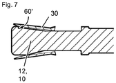
- a method for using the anchor is illustrated in figures 4 to 7 .
- the anchor is introduced, front end first, into a hole in a substrate 6.
- the expansion body 12 is drawn into the front-end region of the expansion sleeve 30, i.e. the expansion sleeve 30 is pushed forwards relatively to the expansion body 12 and over the expansion body 12.
- this is achieved by pulling the anchor bolt 10 together with the expansion body 12 rearwardly, in particular by tightening a nut 8 provided on the tension-introducing structure 18 of the anchor bolt 10. Since the substrate 6 exerts radial pressure on the expansion sleeve 30, the expansion sleeve 30 slightly bend radially into the abutment wall recesses 66', 66", 66''' when the expansion body 12 is drawn into the front-end region of the expansion sleeve 30.
- Figures 5 to 7 show consecutive positions of the expansion sleeve 30 relative to the expansion body 12 during drawing-in of the expansion body 12.
- the expansion sleeve 30 axially hits, with its tip in the bent-in regions, the expansion sleeve abutment walls 60', 60", 60"'. This results in a form-fit type axial interlock of the expansion sleeve 30 with the expansion body 12 at the expansion sleeve abutment walls 60', 60", 60"'. This interlock leads to a temporary change of the expansion mechanism and can result in increased pull-out resistance without excessive stress of the substrate 6.
- the interface between the expansion sleeve abutment walls 60', 60", 60''' and the expansion sleeve 30 is so designed that the interlock can be overcome on purpose at high tensile loads, as shown in figure 7 , leading to a return of the expansion mechanism, and potentially to particularly good resistance at high loads.
- Tightening of the nut 8 might induce rotation of the expansion body 12 relative to the expansion sleeve 30 at the beginning of installation. But this rotation is soon stopped, namely when the edge of a slit engages a side wall of one of the abutment wall recesses 66', 66", 66''', e.g. when the edge of slit 36" engages side wall 69" of recess 66", as shown in figure 5 .
Abstract
The invention relates to an expansion anchor having an anchor bolt, an expansion sleeve surrounding the anchor bolt, and an expansion body located in a front region of the anchor bolt, wherein the expansion body has a converging zone for expanding the expansion sleeve. According to the invention, the expansion body has at least one expansion sleeve abutment wall facing the expansion sleeve. The invention also relates to a method for using such an expansion anchor.
Description
- The invention relates to an expansion anchor according to the preamble of claim 1. Such an anchor is provided with an anchor bolt, an expansion sleeve surrounding the anchor bolt, and an expansion body located in a front region of the anchor bolt, wherein the expansion body has a converging zone for expanding the expansion sleeve.
-
WO 15067578 A1 -
EP2848825 A1 discloses an expansion anchor in which the expansion sleeve has at least one web on its inner side, which web engages a groove in the anchor bolt. During installation, this web is displaced radially outwardly by the expansion body of the bolt. -
EP2514979 A1 shows an anchor bolt with an eccentric region that widens the expansion sleeve upon rotation of the anchor bolt. -
EP2309138 A2 shows an expansion body having longitudinal edges. -
DE2256822 A1 discloses an expansion anchor, in which a rotation lock is provided between the expansion sleeve and the anchor bolt. This rotation lock might be formed by a groove extending into the expansion body of the bolt, and a corrsponding protrusion, which protrudes from the expansion sleeve. In one embodiment ofDE2256822 A1 , the groove extends axially all along the expansion body and the protrusion extends axially all along the expansion sleeve. In another embodiment, the protrusion is shorter and offset from the expansion sleeve tip towards the rear end of the expansion sleeve. -
WO12126700 A1 -
EP 0515916 A2 andDE3411285 A1 describe fasteners. In both cases, sleeves interlock with inner bolts via toothings. - It is an object of the present invention to provide an expansion anchor that has particularly high performance, whilst being easy to manufacture.
- This objective is achieved by an expansion anchor according to claim 1. The dependent claims describe preferred embodiments.
- An inventive anchor is characterized in that the expansion body has at least one expansion sleeve abutment wall facing the expansion sleeve.
- A first basic idea of the present invention may be seen in providing the expansion body with at least one expansion sleeve abutment wall, which expansion sleeve abutment wall faces the expansion sleeve before installation of the anchor, so that the expansion sleeve can hit the expansion sleeve abutment wall when the expansion body moves along the expansion sleeve during expansion of the expansion sleeve, when the anchor is installed. It has been unexpectedly discovered that this can significantly improve anchor performance. The following mechanism can explain the observed improvement: When the tip of the expansion sleeve touches the expansion sleeve abutment wall, a kind of temporary form fit can be generated between the expansion sleeve and the expansion body. This form fit can increase the resistance against pull-out of the expansion body out of the expansion sleeve, but it can do so advantageously without significant additional expansion of the expansion sleeve, i.e. without increasing the expansion force significantly. Due to the low expansion force, the substrate that surrounds the anchor, e.g. concrete, will not be overstressed, whereas the pullout loads remarkably increase. Thus, due to the interlock between expansion sleeve abutment wall and expansion sleeve, concrete capacity can increase significantly above the level of standard expansion anchors. Moreover, since the interlock between expansion sleeve abutment wall and expansion sleeve can reduce relative movement between expansion sleeve and expansion body plus anchor bolt, the total anchor displacement behavior, in particular in cyclic load cracked concrete conditions can also be improved.
- The anchor bolt is an elongate body. The expansion body and the anchor bolt are, in particular, connected to transfer tensile forces. The expansion body can for example be threaded to the anchor bolt, in particular if the expansion anchor is a so-called sleeve-type expansion anchor. The expansion body can also be tightly fixed to the anchor bolt, in particular if the expansion anchor is a so-called stud-type expansion anchor. It is particularly preferred in case of a stud-type expansion anchor that the expansion body and the anchor bolt are integral, i.e. that they form one piece. If the expansion anchor is a so-called stud-type expansion anchor, the anchor bolt is preferably provided with a forwardly-facing shoulder for expansion sleeve abutment and for advancing the expansion sleeve into the borehole. The expansion body is a part of the expansion anchor.
- The expansions sleeve surrounds the anchor bolt, in particular around the longitudinal axis. Preferably, the expansion sleeve is a single piece. However, it could also consist of several individual segments, which are for example held in a bolt-surrounding arrangement by means of a rubber band or by snap-on mechanisms.
- Preferably, the anchor bolt, the expansion sleeve and/or the expansion body are each steel parts. They can for example comprise carbon steel or stainless steel.
- The anchor bolt can have, in a rear region of the anchor bolt, a tension-introducing structure. The tension-introducing structure is for introducing tensile force into the anchor bolt. The tension-introducing structure can for example be a thread, in particular an outer thread, provided on the anchor bolt. The tension-introducing structure can for example also be a head, that forms a maximum cross-section, or a bayonet-type lock.
- The converging zone of the expansion body serves to expand the expansion sleeve when the expansion sleeve is moved forward with respect to the expansion body, in particular to expand the expansion sleeve radially with respect to the longitudinal axis. In the converging zone, the expansion body converges, on its lateral surface, towards the rear of the anchor bolt and/or towards the tension-introducing structure, wherein the focus of convergence can preferably be the longitudinal axis. This in particular implies that the radial distance of the lateral surface of the expansion body from the longitudinal axis becomes smaller towards the rear of the expansion body. The expansion body can have additional zones, for example a preferably cylindrical transition zone and/or a tip zone. The converging zone can for example be conical, or can have a more complex, for example a convex or concave shape. In particular, the converging zone forms a wedge for the expansion sleeve.
- The expansion sleeve abutment wall is for creating an interlock between the expansion body and the expansion sleeve. The expansion sleeve abutment wall is so arranged that the expansion sleeve can hit the expansion sleeve abutment wall, i.e. that the expansion sleeve can abut on the expansion sleeve abutment wall, when the expansion sleeve is axially displaced relative to the expansion body in the forwards direction, i.e. towards the front end of the expansion body and/or the anchor bolt, in particular by drawing-in the expansion body into the expansion sleeve in the rearwards direction. Thus, the expansion sleeve abutment wall axially faces the expansion sleeve, or, in other words, the expansion sleeve abutment wall faces the expansion sleeve in a direction parallel to the longitudinal axis. Preferably, the expansion sleeve abutment wall faces, in particular axially faces, the tip of the expansion sleeve and/or serves for abutment of the tip of the expansion sleeve, and can therefore be named expansion sleeve tip abutment wall. The tip of the expansion sleeve can be understood to be the front end of the expansion sleeve, i.e. the end pointing in the forwards direction. The expansion sleeve abutment wall is arranged vis-à-vis, in particularly axially vis-à-vis, the expansion sleeve, and particularly the tip of the expansion sleeve. In particularly, the expansion sleeve abutment wall faces, in particular axially faces, the expansion sleeve, in particular the expansion sleeve tip, in a state before the expansion sleeve is expanded by the expansion body, i.e. in the pre-installation state of the anchor, before the anchor is installed. In particular, the expansion sleeve abutment wall faces towards the rear of the anchor. The inventive anchor is so configured that the expansion sleeve, in particular with its tip, can hit the at least one expansion sleeve abutment wall during axial displacement of the expansion body relative to the expansion sleeve in the rearwards direction and/or during radial expansion of the expansion sleeve by the expansion body. Thus the at least one expansion sleeve abutment wall is suitable and/or configured for being abutted on by the expansion sleeve, in particular axially and/or by the tip of the expansion sleeve. In particular, the at least one expansion sleeve abutment wall is suitable and/or configured for being abutted on, in particular axially abutted on, by a section, in particular a front-end section, of the expansion sleeve, which section is curved around the longitudinal axis and/or designated to be radially displaced by the expansion body.
- In particular, the expansion sleeve abutment wall projects radially on the expansion body and/or a step structure is formed at the expansion sleeve abutment wall, wherein the expansion sleeve abutment wall forms the riser of the respective step structure. The expansion sleeve abutment wall is arranged on the lateral surface of the expansion body, i.e. on the side of the expansion body.
- The at least one expansion sleeve abutment wall might be straight in side view of the anchor bolt, permitting a simple structural design. However, the at least one expansion sleeve abutment wall may also be curved in side view of the anchor bolt, or it may, in side view of the anchor bolt, consist of several wall segments, for example straight wall segments, that are connected in an angled relationship to give a single expansion sleeve abutment wall. In particular, the at least one expansion sleeve abutment wall may form a concavity in side view of the anchor bolt, which might be advantageous from a manufacturing point of view. The radial height of the expansion sleeve abutment wall relative to its wall base can be constant, but might also vary.
- Where the term "longitudinal axis" is used, this should, in particular, refer to the longitudinal axis of the anchor bolt, which is often also the longitudinal axis of the anchor. In accordance with the usual definition, the "longitudinal axis" can in particular be the axis that runs in the longitudinal direction, i.e. in the long direction of the elongate anchor bolt. Where the terms "radially", "axially" or "circumferentially" are used, this is should in particular be understood with respect to the longitudinal axis of the anchor bolt.
- As explained in more detail above, the axial interlock between the expansion sleeve and the expansion body, generated by the at least one expansion sleeve abutment wall, can advantageously improve anchor performance. In addition to this, it was unexpectedly discovered that it is particularly advantageous when the form-fit interlock between the expansion sleeve and the expansion body generated by the at least one expansion sleeve abutment wall is significant, but not too strong. In other words, it is advantageous when the expansion sleeve abutment wall only "brakes" the expansion sleeve, without completely stopping it, i.e. when the expansion sleeve abutment wall can be surmounted by the expansion sleeve, on purpose and in particular without destroying the anchor. In particular, it was discovered that a complete stop of the expansion sleeve could lead to pull-out type of failure at high loads, which is an often undesired, premature pattern. This could be explained by a change of anchor characteristics from expansion-type to frictional-type when a hard stopping expansion sleeve abutment wall is hit by the expansion sleeve. In contrast, if the expansion sleeve abutment wall is designed to be surmounted by the expansion sleeve, the anchor characteristics can, at least partly, revert to expansion-type at high loads, which allows to activate expansion reserves at the expansion sleeve so that maximum load capacity can be further increased, preferably up to concrete cone failure. Thus, having the expansion sleeve abutment wall surmountable by the expansion sleeve can create a particularly long and smooth force-displacement characteristic of the anchor.
- In view of the above, it is particularly advantageous if the at least one expansion sleeve abutment wall is designed for surmountably obstructing the expansion sleeve, in particularly for surmountably obstructing axial movement of the expansion sleeve. "Obstructing" implies here that an interlock can be created, "surmountably" that the interlock can be, on purpose, overcome, in particular at high loads. Such a surmountably obstruction can for example be created by having the expansion sleeve tip or/and the expansion sleeve abutment wall slanted along the axial direction, so that the expansion sleeve abutting on the expansion sleeve abutment wall is pushed radially outwards at high axial loads by a wedge effect, until the expansion sleeve can axially surmount the expansion sleeve abutment wall.
- It is particularly advantageous if the least one expansion sleeve abutment wall tapers towards the rear of the anchor bolt. Thus, preferably, the expansion sleeve abutment wall is, at least in total, non-perpendicular to the longitudinal axis. Rather, the radius of the expansion body gradual decreases towards the rear of the anchor bolt at the expansion sleeve abutment wall. This allows creating a surmountable obstruction in a particularly reliable and easy-to-manufacture way. Preferably, the maximum slope αmax of the at least one expansion sleeve abutment wall, measured with respect to the longitudinal axis of the anchor bolt, is smaller than 80° or 70°, which means that no point of the expansion sleeve abutment wall has larger slope. It has been observed that at higher angles, the interlock might be too tight for certain situations. In accordance with usual definition, the slope measured with respect to the longitudinal axis can in particular be understood to be the angle between a tangent line at a point of the wall and the longitudinal axis, measure in a longitudinal plane, i.e. in a plane that contains the longitudinal axis.
- Also, preferably, the maximum slope αmax of the at least one expansion sleeve abutment wall, measured with respect to the longitudinal axis of the anchor bolt, is greater than 30°. Having this lower boundary for the slope ensures particularly reliable interlock and can maximize capacity in a particularly simple way.
- In another advantageous embodiment, the at least one expansion sleeve abutment wall has a maximum radial height h60, i.e. a greatest height measured radially with respect to the longitudinal axis, from abutment wall base to abutment wall top, of at least 0.3 mm. This lower boundary allows a particular reliable engagement of the expansion sleeve at the expansion sleeve abutment wall with expansion sleeve types usually used for expansion anchors. Where the height of the at least one expansion sleeve abutment wall is constant, its maximum height is this constant height.
- Preferably, the at least one expansion sleeve abutment wall is located at a distance d60, in particular axial distance d60, of at least 0,5*L1, preferably of at least 0,8*L1, from the rear end of the converging zone, wherein L1 is the length, in particular axial length, of the converging zone. Thus, the at least one expansion sleeve abutment wall is preferably located relatively far forward on the expansion body, so that the interlock with the expansion sleeve is only then generated when the expansion sleeve is already safely anchored. Therefore, premature pull-out can be efficiently avoided and concrete usage can be improved.
- The expansion body can have, located in front of the converging zone, a transition zone. In such a transition zone, the convergence of the expansion body is at least less steep as compared with the converging zone, or the convergence can be completely absent. Such a transition zone can prevent over-expanding the expansion sleeve and over-stressing the surrounding substrate at high loads. If convergence is completely absent, the transition zone can have a cylindrical lateral surface, wherein cylindrical is to be understood in a broad definition, in which the cylinder base can be, but does not necessarily has to be circular.
- If a transition zone is provided, the at least one expansion sleeve abutment wall is preferably located within the transition zone. This can result in a particularly well-coordinated activation of the expansion sleeve abutment wall and therefore particularly good load characteristics. In particular, the expansion sleeve abutment wall will in this case not be engaged by the expansion sleeve before a late expansion phase, in which the expansion sleeve is already safely anchored and increase of pressure on the substrate is relatively low. In this phase, the contribution of the interlock can be particularly efficient. Thus, concrete usage can be further improved.
- The at least one expansion sleeve abutment wall can for example be located on a protrusion that radially projects from the expansion body. However, according to another preferred finding of the invention, the expansion body can be provided, in particular on its lateral surface, with at least one abutment wall recess, wherein the at least one abutment wall recess is limited, in particular at its front end, by the at least one expansion sleeve abutment wall. Thus, the expansion sleeve abutment wall forms the front-end wall of a recess. This can have a number of advantages: a) a recess can be particularly easy to manufacture, b) a wall formed at the end of a recess, i.e. an at least partly sunken wall, can be particularly robust, c) an at least partly sunken wall is less prone to undesired interference with the expansion mechanism or with the hole wall, and d) the recess can have additional preferable functions, amongst others substrate stress relieve. In particular, it has been found that if the recess is so designed that the expansion sleeve enters the recess upon being moved forwards relative to the expansion body, in particular by bending-in, pressure or, in particular, pressure-spikes on the substrate can be reduced, as will be explained in more detail below. Since the expansion sleeve abutment wall is located at the end of the recess, this pressure relief is "automatically" coordinated with the activation of the expansion sleeve abutment wall, which can further improve performance without much effort. Thus, it is particularly preferred if the anchor is so configured that the abutment wall recess receives a section of the expansion sleeve, in particular when the expansion sleeve is moved forwards relatively to the expansion body, i.e. when the expansion body is moved rearwards relatively to the expansion sleeve, and/or when the expansion sleeve is expanded by the expansion body, in particular by bending-in. Since the size of the recess is finite, only a part of the expansion sleeve gets into to the recess, whereas the other part of the expansion sleeve expands fully along the expansion body surface. Thus, concrete stress is reduced without significantly reducing expansion rate.
- In particular, the at least one abutment wall recess extends radially into the expansion body. The at least one abutment wall recess is preferably at least partly located in the converging zone of the expansion body.
- The expansion sleeve can have at least one slit, originating from the front end of the expansion sleeve. The slit can be due to manufacturing reasons, in particular if the expansion sleeve is manufactured by rolling a sheet material around the anchor bolt. Alternatively or additionally, the at least one slit can be provided for assisting expansion of the expansion sleeve. Preferably, the expansion sleeve has a plurality of slits originating from the front end of the expansion sleeve, and the expansion sleeve has fingers between neighboring slits.
- It was discovered that a slit originating from the front end of the expansion sleeve can be the cause of particular substrate stress, since it forms a strong discontinuity that can, as such, potentially generate pressure spikes. Particularly in view of this, it is preferred that the at least one slit is located in a position where it at least partly overlaps the at least one abutment wall recess or can at least be brought into this position by rotating the expansion sleeve around to the anchor bolt, in particular without destroying the anchor. In such an overlapping position, the vicinity of the slit can engage into the abutment wall recess. It was found that this can significantly reduce the undesired pressure spikes. The overlap is in particular meant to be a radial overlap. Bringing the slit into an overlapping position was found to be often very easy to achieve: A side edge of the recess was found to automatically catch even a freely-rotating expansion sleeve at the slit during installation torqueing, thereby creating a rotational lock at the correct overlapping position.
- If there is a plurality of abutment wall recesses and a plurality of slits originating from the front end of the expansion sleeve, it is particularly preferred, for the same reason, if all the slits are each located in a position where they at least partly overlap at least one of the abutment wall recesses or can at least be brought into this position by rotating the expansion sleeve around to the anchor bolt. Preferably, the number of abutment wall recesses equals the number of slits originating from the front end of the expansion sleeve, which allows tension relief at all slits and a particularly simple design.
- Preferably, the expansion body has an arcuate cross-section adjacent to the at least one abutment wall recess. This can allow a particular uniform loading of the substrate, and can also support the above-mentioned rotational alignment of the slit. In accordance with the usual definition, a cross section is meant to be a section perpendicular to the longitudinal axis here.
- It is particularly advantageous if the at least one expansion sleeve abutment wall has a maximum angular width θmax that is greater than 50°, preferably greater than 60°, particularly preferable of about 70°. In other words, the at least one expansion sleeve abutment wall spans more than 50°, preferably more than 60°, particularly preferable of about 70° of the expansion body. In particular, the maximum angular width is measured at the longitudinal axis of the anchor bolt and/or in a plane perpendicular to the longitudinal axis of the anchor bolt. Preferably, the at least one expansion sleeve abutment wall is axially projected on this plane and the angular width, measured at the longitudinal axis of the anchor bolt, of this projection is taken as maximum angular width of the at least one expansion sleeve abutment wall. Thus, the expansion sleeve abutment wall is relatively broad, which can provide particularly good interlocking with the expansion sleeve, and, if the expansion sleeve abutment wall is provided at an abutment wall recess, this recess will usually have similar size, permitting reliable engagement, in particular bending-in, of the expansion sleeve into the recess, with the stress relief advantages resulting therefrom explained in detail above.
- It is also advantageous if the at least one expansion sleeve abutment wall has a maximum angular width θmax that is smaller than 90°, preferably smaller than 80°. The maximum angular width can be measured as described above. According to this embodiment, the expansion sleeve abutment wall is not too broad. This allows providing axially free sleeve regions, i.e. areas that have no expansion sleeve abutment wall axially in front of them, in a particularly easy way. Axially free sleeve regions can advantageously soften the interlock generated at the expansion sleeve abutment wall and/or they can allow a mixed expansion mechanism, which allows the system to adjust to particular load situations in a particularly easy and efficient way.
- It is particularly preferred if the expansion body has a plurality of expansion sleeve abutment walls, in particular minimum 2 or minimum 3 expansion sleeve abutment walls. Having a plurality of expansion sleeve abutment walls can provide for a particularly uniform load distribution and therefore, whilst being easy to manufacture, for a particularly reliable interlock of the expansion sleeve. Moreover, it can avoid peak loads at the anchor and/or the surrounding concrete, thereby further improving performance. Moreover, it can facilitate the design of advantageous axially free sleeve regions, which can further improve performance at low costs. The individual expansion sleeve abutment walls are, in particular, separate and/or distinguishable from another.
- In this text, reference is repeatedly made to the properties of "at least one expansion sleeve abutment wall". If, according to the invention, there is provided a plurality of expansion sleeve abutment walls, then at least one of the plurality of expansion sleeve abutment walls can have these properties, or all of the plurality of expansion sleeve abutment walls can have these properties, unless explicitly stated otherwise.
- It is particularly preferred that the expansion sleeve abutment walls are arranged abreast, i.e. that they overlap in the axial direction. Preferably, there is at least on plane perpendicular to the longitudinal axis that intersects all expansion sleeve abutment walls. This allows for a particularly well-coordinated and therefore efficient interlock with usual sleeve structures.
- According to a preferred embodiment, the expansion sleeve abutment walls span, in total, θtotal minimum 120°, preferably minimum 140° or, particularly preferably, minimum 160° of the expansion body. In other words, when the expansion sleeve abutment walls are all axially projected (i.e. projected using rays that run parallel to the longitudinal axis) on a plane perpendicular to the longitudinal axis, and the total angle covered by the projections of these walls in this plane is determined, this total angle is minimum 120°, preferably minimum 140° or, particularly preferably, minimum 160°. Thus, the expansion sleeve abutment walls are relatively broad in total, which provides for a particularly effective interlock.
- According to another preferred embodiment, the expansion sleeve abutment walls span, in total, θtotal maximum 250° or maximum 280° of the expansion body. In other words, when the expansion sleeve abutment walls are all axially projected (i.e. projected using rays that run parallel to the longitudinal axis) on a plane perpendicular to the longitudinal axis, and the total angle covered by the projections of these walls in this plane is determined, this total angle is maximum 280°, preferable maximum 250°. This leaves significant axially free sleeve regions that have no expansion sleeve abutment wall in front of them, which can efficiently allow the system to adjust to particular load situations, as explained above.
- It is particularly advantageous if the expansion body has maximum 8, preferably
maximum 6, particularly preferable maximum 4, expansion sleeve abutment walls. Thus, there is relatively few expansion sleeve abutment walls and, if present, also relatively few abutment wall recesses. This allows to design the respective expansion sleeve abutment walls and, if present, the abutment wall recesses particularly effective in a particularly easy way. In particular, since there are only few elements, they can be made relatively broad without requiring complex designs. Broad expansion sleeve abutment walls, in turn, allow effective interlock and broad abutment wall recesses allow effective expansion sleeve engagement, resulting in effective stress relief and/or rotational interlock. - As already mentioned before, the individual expansion sleeve abutment walls may be straight, but also curved or segmented in side view of the anchor bolt. In the latter case, the individual sleeve abutment walls may, in side view of the anchor bolt, each consist of several wall segments, e.g. straight wall segments, that are connected in an angled relationship to give a common expansion sleeve abutment wall in each case.
- In addition to the at least one expansion sleeve abutment wall, the expansion body might be provided with additional walls, e.g. recess side walls, which additional walls do not axially face the expansion sleeve and/or which additional walls are not suitable for expansion sleeve abutment upon axial displacement of the expansion sleeve, and which therefore cannot be termed expansion sleeve abutment walls.
- If there is more than one expansion sleeve abutment wall, it is preferable that the expansion body is provided, in particular on its lateral surface, with a plurality of abutment wall recesses, wherein each abutment wall recess is limited, in particular at its respective front end, by one of the expansion sleeve abutment walls. This allows to achieve the advantages described above in context with a single recess in a multi-wall setup, wherein the provision of several recesses can increase their performance and ease of use. For example, a plurality of recesses can allow early engagement of an individual slit or simultaneous engagement of several slits of the expansion sleeve.
- When there is a plurality of abutment wall recesses, it is advantageous if the plurality of expansion sleeve abutment walls cover 20% to 70%, preferably 40% to 45%, of the lateral surface of the expansion body, in particular of the lateral surface of the converging zone, or, where a transition zone is present, of the lateral surface of the converging zone plus transition zone. This allows the recesses to be particularly effective.
- Preferentially, the expansion sleeve abutment walls are arranged in a symmetric manner, the expansion sleeve abutment walls are arranged equidistantly around the expansion body, and/or the expansion sleeve abutment walls all have equal widths, all within usual manufacturing tolerances. Such symmetric setups can improve load balance, and can therefore further improve performance.
- It is particularly preferred if the maximum thickness t30 of the expansion sleeve is between 0.75mm and 3.5mm. This allows particularly good interlock with the expansion sleeve abutment wall and/or engagement with the abutment wall recess. In particular, thickness of the expansion sleeve can be measured in the radial direction, in accordance with usual definition.
- Preferentially, the converging zone has an apex angle β between 10° and 40, particularly between 26° and 40°. If the apex angle β is larger, there is an increased probability of the effect of the steep expansion sleeve abutment wall being masked by the already steep converging zone. If it is smaller, substrate loading would be high, even when there is interlock at the expansion sleeve abutment wall.
- Preferably, the maximum diameter of the anchor bolt and/or the expansion zone is less than 30 mm or 25 mm. The invention can be particularly useful for relatively small anchors.
- The invention also relates to a method for using, in particular for installing, an inventive expansion anchor, in which the expansion sleeve is moved forwards relative to the expansion body, in particular to expand the expansion sleeve, wherein the expansion sleeve hits the at least one expansion sleeve abutment wall. In particular, the invention also relates to a method for using, in particular for installing, an inventive expansion anchor, in which the anchor is inserted into a hole, and the expansion sleeve is, with the anchor located in the hole, in particular with at least the tip of the expansion sleeve located in the hole, moved forwards relative to the expansion body, wherein the expansion sleeve hits the at least one expansion sleeve abutment wall. Accordingly, the anchor is used and/or installed as intended. Moving the expansion sleeve forwards relative to the expansion body, i.e. moving the expansion body rearwards relative to the expansion sleeve, can preferably be achieved by pulling the anchor bolt, with the expansion body attached, out of the hole or/and by moving the expansion body rearwards relative to the anchor bolt. It could, in principle, also be achieved by pushing the expansion sleeve forwards over an expansion body that is axially stationary within the hole.
- Preferably, the expansion sleeve is moved forwards relative to the expansion body, wherein the expansion sleeve hits the at least one expansion sleeve abutment wall and subsequently overcomes the at least one expansion sleeve abutment wall. Thus, the expansion sleeve abutment wall is axially surmounted, as advantageously intended at high loads.
- Moreover, it is advantageous if the expansion sleeve is moved forwards relative to the expansion body, wherein a region of the expansion sleeve is inserted into at least one abutment wall recess. This can for example reduce concrete stress or generate a rotational lock, as described in more detail above.
- Features which are described here in context with the anchor can also be used for the method for using the anchor, and features that are described here in context with the method for using the anchor can also be used for the anchor itself.
- The invention is explained in greater detail below with reference to preferred exemplary embodiments, which are depicted schematically in the accompanying drawing, where individual features of the exemplary embodiments presented below can be implemented either individually or in any combination within the scope of the present invention.
- Figure 1:
- a side view of an inventive expansion anchor,
- Figure 2:
- a cut-out of the front region of the anchor of
figure 1 in sectional view A-A according tofigure 1 ; - Figure 3:
- a cross-sectional view B-B according to
figure 1 of the anchor offigures 1 and 2 ; - Figures 4 to 7:
- consecutive steps of a method for using the anchor of
figures 1 to 3 in a substrate, wherein, for the sake of clarity, the substrate is only shown infigure 4. Figure 4 shows the anchor in side view,figure 5 in cut-out detail side view andfigures 6 and7 in cut-out sectional view, similar tofigure 2 . - The figures show an embodiment of an inventive expansion anchor. The anchor comprises an
elongate anchor bolt 10 defining alongitudinal axis 99, anexpansion sleeve 30, which surrounds theanchor bolt 10, and anexpansion body 12 for theexpansion sleeve 30 provided on theanchor bolt 10, namely in the vicinity of the front end of theanchor bolt 10. - As shown in particular in
figure 2 , theexpansion body 12 has a convergingzone 23 designed for radially expanding theexpansion sleeve 30 when theexpansion body 12 is drawn into theexpansion sleeve 30 in the rearwards direction, i.e. when theexpansion sleeve 30 is moved forwards relative to theexpansion body 12 onto theexpansion body 12. For this purpose, the lateral surface of theexpansion body 12 converges towards the rear of the anchor, i.e. it converges towards theexpansion sleeve 30, at least before the anchor is installed. In the present example, theexpansion body 12 lateral surface is conical in the convergingzone 23, with a focus of convergence on thelongitudinal axis 99 and with apex angle β shown infigure 1 . However, this is merely an example and other converging designs are also possible. - In the present example, the
expansion body 12 also has atransition zone 22, which is located forwards of and adjacent to the convergingzone 23, and atip zone 21, which is located forwards of and adjacent to thetransition zone 22. In thetransition zone 22, the rearward convergence is smaller as compared to the convergingzone 23 or the rearward convergence is even zero, but preferably not reverse, i.e. it is not a forward convergence. In the present example, convergence is absent, i.e. zero, in the convergingzone 23 and theexpansion body 12 has a cylindrical lateral surface in the convergingzone 23, in particular cylindrical with a circular base. In thetip zone 21, the lateral surface of theexpansion body 12 converges towards the front end of the anchor. - The
anchor bolt 10 has aneck 25, which is located adjacent to and rearwards of theexpansion body 12. Theexpansion sleeve 30 at least partly surrounds thisneck 25, at least before installation the anchor. At theneck 25, the diameter of theanchor bolt 10 can be minimal. - In the present embodiment, the anchor is of the stud type. The
bolt 10 has, at the rearward end of theneck 25, ashoulder 17 facing forwards for axially engaging theexpansion sleeve 30 and for advancing theexpansion sleeve 30 forwards. In the present case, theexpansion body 12 is, by way of example, integral with theanchor bolt 10. - In a rear region of the
anchor bolt 10, theanchor bolt 10 is provided with a tension-introducingstructure 18, here in the form of an outer thread provided on theanchor bolt 10. - The
expansion sleeve 30 is provided with a plurality ofslits 36', 36", which originate from the front end of theexpansion sleeve 30 and extend towards the rear end of theexpansion sleeve 30. Theslits 36', 36" facilitate radial expansion of theexpansion sleeve 30. Theexpansion sleeve 30 has a maximum radial thickness t30 shown infigure 2 . - On the lateral surface of the
expansion body 12 is provided a plurality of abutment wall recesses 66', 66", 66''' (exemplarily three in the present case, but a different number can be also provided). These abutment wall recesses 66', 66", 66''' are radially accessible from the outside of theexpansion body 12. By way of example, they each have a roughly rectangular contour when seen in side view. Other contours are possible, however. - Each of the abutment wall recesses 66 is terminated at its front end by an expansion
sleeve abutment wall 60. As there are three abutment wall recesses 66', 66", 66''' in the present example, there are also three expansionsleeve abutment walls 60', 60", 60'''. Each of these expansionsleeve abutment walls 60', 60", 60''' faces theexpansion sleeve 30, i.e. faces rearwardly, and forms a surmountable axial stop for the front end, i.e. for the tip, of theexpansion sleeve 30, as will be described in more detail below. - As shown in
figure 2 and, by way of example, at expansion sleeve abutment wall 60', each of the expansionsleeve abutment walls 60', 60", 60''' has a radial height h60 and a maximum slope αmax, measured longitudinally with respect to thelongitudinal axis 99. As shown infigure 3 and, by way of example, at expansion sleeve abutment wall 60', each of the expansionsleeve abutment walls 60', 60", 60''' has a maximum angular width θmax, in cross section and around thelongitudinal axis 99. In total, all expansionsleeve abutment walls 60', 60", 60''' span a total angle θtotal around thelongitudinal axis 99. The expansionsleeve abutment walls 60', 60", 60''' are abreast, located at the same position along thelongitudinal axis 99, and do not overlap in the circumferential direction. Therefore, θtotal is here the sum of the maximum angular widths θmax of all expansionsleeve abutment walls 60', 60", 60"', i.e. θtotal = Σ θmax. - The expansion
sleeve abutment walls 60', 60", 60''' are all located in thetransition zone 22. In particular, as shown infigure 2 and, by way of example, at expansion sleeve abutment wall 60', each of the expansionsleeve abutment walls 60', 60", 60''' is located at a distance d60 from the axial rear end of theexpansion body 12, i.e. from the rear end of the convergingzone 23, which distance d60 is greater than the axial length L1 of the convergingzone 23. - A method for using the anchor is illustrated in
figures 4 to 7 . - In a first step of the method, shown in
figure 4 , the anchor is introduced, front end first, into a hole in asubstrate 6. - Subsequently, the
expansion body 12 is drawn into the front-end region of theexpansion sleeve 30, i.e. theexpansion sleeve 30 is pushed forwards relatively to theexpansion body 12 and over theexpansion body 12. In the present embodiment, this is achieved by pulling theanchor bolt 10 together with theexpansion body 12 rearwardly, in particular by tightening anut 8 provided on the tension-introducingstructure 18 of theanchor bolt 10. Since thesubstrate 6 exerts radial pressure on theexpansion sleeve 30, theexpansion sleeve 30 slightly bend radially into the abutment wall recesses 66', 66", 66''' when theexpansion body 12 is drawn into the front-end region of theexpansion sleeve 30.Figures 5 to 7 show consecutive positions of theexpansion sleeve 30 relative to theexpansion body 12 during drawing-in of theexpansion body 12. - At some stage, as shown in
figure 6 , theexpansion sleeve 30 axially hits, with its tip in the bent-in regions, the expansionsleeve abutment walls 60', 60", 60"'. This results in a form-fit type axial interlock of theexpansion sleeve 30 with theexpansion body 12 at the expansionsleeve abutment walls 60', 60", 60"'. This interlock leads to a temporary change of the expansion mechanism and can result in increased pull-out resistance without excessive stress of thesubstrate 6. - The interface between the expansion
sleeve abutment walls 60', 60", 60''' and theexpansion sleeve 30 is so designed that the interlock can be overcome on purpose at high tensile loads, as shown infigure 7 , leading to a return of the expansion mechanism, and potentially to particularly good resistance at high loads. - Tightening of the
nut 8 might induce rotation of theexpansion body 12 relative to theexpansion sleeve 30 at the beginning of installation. But this rotation is soon stopped, namely when the edge of a slit engages a side wall of one of the abutment wall recesses 66', 66", 66''', e.g. when the edge ofslit 36" engagesside wall 69" ofrecess 66", as shown infigure 5 .
Claims (22)
- Expansion anchor having- an anchor bolt (10),- an expansion sleeve (30) surrounding the anchor bolt (10), and- an expansion body (12) located in a front region of the anchor bolt (10), wherein the expansion body (12) has a converging zone (23) for expanding the expansion sleeve (30),characterized in that- the expansion body (12) has at least one expansion sleeve abutment wall (60) facing the expansion sleeve (30).
- Expansion anchor according to claim 1,
characterized in that
the at least one expansion sleeve abutment wall (60) is for surmountably obstructing the expansion sleeve (30). - Expansion anchor according to one of the preceding claims,
characterized in that
the least one expansion sleeve abutment wall (60) tapers towards the rear of the anchor bolt (10). - Expansion anchor according to one of the preceding claims,
characterized in that
the maximum slope (αmax) of the at least one expansion sleeve abutment wall (60), measured with respect to the longitudinal axis (99) of the anchor bolt (10), is greater than 30° and/or smaller than 80°. - Expansion anchor according to one of the preceding claims,
characterized in that
the at least one expansion sleeve abutment wall (60) has a maximum radial height (h60) of at least 0.3 mm. - Expansion anchor according to one of the preceding claims,
characterized in that
the at least one expansion sleeve abutment wall (60) is located at a distance (d60) of at least 0,5*L1, preferably of at least 0,8*L1, from the rear end of the converging zone (23), wherein L1 is the length of the converging zone (23). - Expansion anchor according to one of the preceding claims,
characterized in that
the expansion body (12) has, located in front of the converging zone (23), a transition zone (22),
wherein the at least one expansion sleeve abutment wall (60) is located within the transition zone (22). - Expansion anchor according to one of the preceding claims,
characterized in that
the expansion body (12) is provided with at least one abutment wall recess (66), wherein the at least one abutment wall recess (66) is limited by the at least one expansion sleeve abutment wall (60). - Expansion anchor according to claim 8,
characterized in that
the abutment wall recess (66) is an abutment wall recess (66) for receiving a section of the expansion sleeve (30). - Expansion anchor according to one of claims 8 or 9,
characterized in that
the expansion sleeve (30) has at least one slit (36), originating from the front end of the expansion sleeve (30),
wherein the at least one slit (36) is located in a position where it at least partly overlaps the at least one abutment wall recess (66) or can at least be brought into this position by rotating the expansion sleeve (30) around to the anchor bolt (10). - Expansion anchor according to one of claims 8 to 10,
characterized in that
the expansion body (12) has an arcuate cross-section adjacent to the at least one abutment wall recess (66). - Expansion anchor according to one of the preceding claims,
characterized in that
the at least one expansion sleeve abutment wall (60) has a maximum angular width (θmax), measured at the longitudinal axis (99) of the anchor bolt (10) in a plane perpendicular to the longitudinal axis (99) of the anchor bolt (10), that is greater than 50°, preferably greater than 60°, and/or smaller than 90°, preferably smaller than 80°. - Expansion anchor according to one of the preceding claims,
characterized in that
the expansion body (12) has a plurality of expansion sleeve abutment walls (60). - Expansion anchor according to claim 13,
characterized in that
the expansion sleeve abutment walls (60) are arranged abreast. - Expansion anchor according to one of claims 13 or 14,
characterized in
that the expansion sleeve abutment walls (60) span, in total, minimum 120°, minimum 140° or minimum 160° of the expansion body (12), and/or
that the expansion sleeve abutment walls (60) span, in total, maximum 280° or maximum 250° of the expansion body (12). - Expansion anchor according to one of claims 13 to 15,
characterized in that
the expansion body (12) has maximum 8, preferably maximum 6, particularly preferably maximum 4 expansion sleeve abutment walls (60). - Expansion anchor according to one of claims 13 to 16,
characterized in that
the expansion body (12) is provided with a plurality of abutment wall recesses (66), wherein each abutment wall recess (66) is limited by one of the expansion sleeve abutment walls (60), wherein
the plurality of abutment wall recesses (66) cover 20% to 70%, preferably 40% to 45%, of the lateral surface of the expansion body (12). - Expansion anchor according to one of claims 13 to 17,
characterized in that
the expansion sleeve abutment walls (60) are arranged in a symmetric manner,
the expansion sleeve abutment walls (60) are arranged equidistantly around the expansion body (12), and/or
the expansion sleeve abutment walls (60) all have equal widths. - Expansion anchor according to one of the preceding claims,
characterized in that
the maximum thickness (t30) of the expansion sleeve (30) is between 0.75mm and 3.5mm, and/or
the converging zone (23) has an apex angle (β) between 10° and 40°. - Method for using an expansion anchor according to one of the preceding claims, in which- the expansion sleeve (30) is moved forwards relative to the expansion body (12), wherein the expansion sleeve (30) hits the at least one expansion sleeve abutment wall (60).
- Method according to claim 20,
characterized in that- the expansion sleeve (30) is moved forwards relative to the expansion body (12), wherein the expansion sleeve (30) hits the at least one expansion sleeve abutment wall (60) and subsequently overcomes the at least one expansion sleeve abutment wall (60). - Method according to claims 20 or 21,
characterized in that- the expansion sleeve (30) is moved forwards relative to the expansion body (12), wherein a region of the expansion sleeve (30) is inserted into at least one abutment wall recess (66).
Priority Applications (15)
| Application Number | Priority Date | Filing Date | Title |
|---|---|---|---|
| EP17198246.5A EP3477125A1 (en) | 2017-10-25 | 2017-10-25 | Expansion anchor with sleeve abutment walls |
| TW107129599A TWI803512B (en) | 2017-10-25 | 2018-08-24 | Expansion anchor with sleeve abutment walls and method for using the same |
| AU2018356242A AU2018356242A1 (en) | 2017-10-25 | 2018-10-17 | Expansion anchor with sleeve abutment walls |
| DK18789128.8T DK3701155T3 (en) | 2017-10-25 | 2018-10-17 | Expansion anchor with socket system wall |
| EP18789128.8A EP3701155B1 (en) | 2017-10-25 | 2018-10-17 | Expansion anchor with sleeve abutment walls |
| PCT/EP2018/078401 WO2019081300A1 (en) | 2017-10-25 | 2018-10-17 | Expansion anchor with sleeve abutment walls |
| KR1020207005041A KR20200067130A (en) | 2017-10-25 | 2018-10-17 | Expansion anchor with sleeve base wall |
| US16/650,770 US11946499B2 (en) | 2017-10-25 | 2018-10-17 | Expansion anchor with sleeve abutment walls |
| CA3073298A CA3073298A1 (en) | 2017-10-25 | 2018-10-17 | Expansion anchor with sleeve abutment walls |
| PL18789128T PL3701155T3 (en) | 2017-10-25 | 2018-10-17 | Expansion anchor with sleeve abutment walls |
| SG11202001399RA SG11202001399RA (en) | 2017-10-25 | 2018-10-17 | Expansion anchor with sleeve abutment walls |
| CN201880053812.9A CN111033060B (en) | 2017-10-25 | 2018-10-17 | Expansion anchor with sleeve abutment wall |
| JP2020510566A JP6975319B2 (en) | 2017-10-25 | 2018-10-17 | Expansion anchor with sleeve contact wall |
| ES18789128T ES2890817T3 (en) | 2017-10-25 | 2018-10-17 | Expansion anchor with sleeve bearing walls |
| RU2020116868A RU2781121C2 (en) | 2017-10-25 | 2018-10-17 | Spacer anchor with thrust walls for sleeve |
Applications Claiming Priority (1)
| Application Number | Priority Date | Filing Date | Title |
|---|---|---|---|
| EP17198246.5A EP3477125A1 (en) | 2017-10-25 | 2017-10-25 | Expansion anchor with sleeve abutment walls |
Publications (1)
| Publication Number | Publication Date |
|---|---|
| EP3477125A1 true EP3477125A1 (en) | 2019-05-01 |
Family
ID=60186073
Family Applications (2)
| Application Number | Title | Priority Date | Filing Date |
|---|---|---|---|
| EP17198246.5A Withdrawn EP3477125A1 (en) | 2017-10-25 | 2017-10-25 | Expansion anchor with sleeve abutment walls |
| EP18789128.8A Active EP3701155B1 (en) | 2017-10-25 | 2018-10-17 | Expansion anchor with sleeve abutment walls |
Family Applications After (1)
| Application Number | Title | Priority Date | Filing Date |
|---|---|---|---|
| EP18789128.8A Active EP3701155B1 (en) | 2017-10-25 | 2018-10-17 | Expansion anchor with sleeve abutment walls |
Country Status (13)
| Country | Link |
|---|---|
| US (1) | US11946499B2 (en) |
| EP (2) | EP3477125A1 (en) |
| JP (1) | JP6975319B2 (en) |
| KR (1) | KR20200067130A (en) |
| CN (1) | CN111033060B (en) |
| AU (1) | AU2018356242A1 (en) |
| CA (1) | CA3073298A1 (en) |
| DK (1) | DK3701155T3 (en) |
| ES (1) | ES2890817T3 (en) |
| PL (1) | PL3701155T3 (en) |
| SG (1) | SG11202001399RA (en) |
| TW (1) | TWI803512B (en) |
| WO (1) | WO2019081300A1 (en) |
Cited By (1)
| Publication number | Priority date | Publication date | Assignee | Title |
|---|---|---|---|---|
| US11719270B2 (en) | 2018-06-20 | 2023-08-08 | Hilti Akiiengesellschaft | Expansion anchor with a nonaxisymmetric recess |
Families Citing this family (4)
| Publication number | Priority date | Publication date | Assignee | Title |
|---|---|---|---|---|
| EP3536985A1 (en) * | 2018-03-05 | 2019-09-11 | HILTI Aktiengesellschaft | Expansion anchor comprising different expansion angles |
| EP3683329A1 (en) * | 2019-01-18 | 2020-07-22 | Hilti Aktiengesellschaft | Expansion anchor with double coating including a zinc flake and/or aluminium flake layer |
| EP4074990A1 (en) | 2021-04-13 | 2022-10-19 | Hilti Aktiengesellschaft | Expansion anchor |
| EP4074991A1 (en) | 2021-04-13 | 2022-10-19 | Hilti Aktiengesellschaft | Expansion anchor |
Citations (11)
| Publication number | Priority date | Publication date | Assignee | Title |
|---|---|---|---|---|
| DE2256822A1 (en) | 1972-11-20 | 1974-06-06 | Manfred Dipl Ing Jost | ANCHORS, IN PARTICULAR DOWELS |
| CH591637A5 (en) * | 1975-04-25 | 1977-09-30 | Huwyler Rudolf | Expansion bolt for concrete blind bore - has tapering portion with rounded convex surface exercising bush expansion pressure |
| DE2744666A1 (en) * | 1977-10-04 | 1979-04-12 | Fischer Artur Dr H C | Building anchor bolt fixture - has conical section at insert end over which slotted bracing socket is fitted |
| US4287807A (en) * | 1979-06-01 | 1981-09-08 | Usm Corporation | Pull-to-set anchoring device |
| DE3411285A1 (en) | 1984-03-23 | 1985-10-03 | Thanh-Son Dipl.-Ing. 1000 Berlin Le | Reusable, frictionally-locked threaded bolt securing device of a screw connection having a threaded bolt and nut |
| EP0515916A2 (en) | 1991-05-27 | 1992-12-02 | UPAT GMBH & CO | Expansible anchor |
| EP2309138A2 (en) | 2009-10-06 | 2011-04-13 | HILTI Aktiengesellschaft | Expansion anchor |
| WO2012126700A1 (en) | 2011-03-23 | 2012-09-27 | Hilti Aktiengesellschaft | Anchor bolt and production method |
| EP2514979A1 (en) | 2011-04-18 | 2012-10-24 | HILTI Aktiengesellschaft | Expansion anchor |
| EP2848825A1 (en) | 2013-09-16 | 2015-03-18 | HILTI Aktiengesellschaft | Split anchor |
| WO2015067578A1 (en) | 2013-11-06 | 2015-05-14 | Hilti Aktiengesellschaft | Expansion anchor with grooves in the expansion cone |
Family Cites Families (20)
| Publication number | Priority date | Publication date | Assignee | Title |
|---|---|---|---|---|
| DE4208016A1 (en) * | 1992-03-13 | 1993-09-16 | Fischer Artur Werke Gmbh | SPREADING DOWEL WITH A SPREADING BODY |
| TW427444U (en) * | 1999-07-29 | 2001-03-21 | Shiu Tai Ping | Improved structure of expansion screw |
| JP2007239804A (en) | 2006-03-06 | 2007-09-20 | Sunrise Kogyo Kk | Anchor bolt |
| JP4630259B2 (en) * | 2006-07-05 | 2011-02-09 | 株式会社パイオラックス | clip |
| CN101235658A (en) * | 2007-01-30 | 2008-08-06 | 刘添兴 | Expansion anchor bolt |
| CN101463854B (en) * | 2009-01-10 | 2013-05-15 | 金拯 | Expansion bolt |
| US7959379B2 (en) * | 2009-03-02 | 2011-06-14 | Robertson Jr Roy Lee | Bolt anchor |
| CN101922492A (en) | 2009-06-17 | 2010-12-22 | 鸿富锦精密工业(深圳)有限公司 | Fixing device |
| CN102052373B (en) * | 2009-10-27 | 2012-08-15 | 中国建筑科学研究院 | Nested tooth surface expansion pipe type expansion anchor bolt |
| DE102010016797A1 (en) | 2010-05-05 | 2011-11-10 | Fischerwerke Gmbh & Co. Kg | expansion anchor |
| CL2011000042A1 (en) * | 2011-01-07 | 2011-06-17 | Fortification system comprising a standard helical bar, an expansion head adapted to the thread of the bar, an element of plastic material, a corrugated plastic tube, a standard fortification plate and a threaded fortification nut according to the helical bolt that use. | |
| FI124908B (en) * | 2011-02-24 | 2015-03-13 | Suomen Metallityö Oy | rock bolt |
| DE102011005999A1 (en) | 2011-03-23 | 2012-09-27 | Hilti Aktiengesellschaft | expansion anchor |
| US20120311947A1 (en) * | 2011-06-07 | 2012-12-13 | John Van Wissen | Expansion anchor |
| CN102182737B (en) * | 2011-06-10 | 2013-06-19 | 温少松 | Invisible pressing expansion screw |
| CN202756368U (en) * | 2012-07-05 | 2013-02-27 | 叶君华 | Anchoring bolt for bonding construction of plate materials |
| EP2886881A1 (en) | 2013-12-19 | 2015-06-24 | HILTI Aktiengesellschaft | Expansion anchor comprising anti-twist device |
| JP6544766B2 (en) * | 2015-05-18 | 2019-07-17 | 株式会社NejiLaw | Fastening device |
| EP3269986A1 (en) * | 2016-07-15 | 2018-01-17 | HILTI Aktiengesellschaft | Expansion dowel with zinc alloy coating |
| CN206257132U (en) * | 2016-08-29 | 2017-06-16 | 内蒙古包钢钢联股份有限公司 | A kind of anti-rotational expansion bolt |
-
2017
- 2017-10-25 EP EP17198246.5A patent/EP3477125A1/en not_active Withdrawn
-
2018
- 2018-08-24 TW TW107129599A patent/TWI803512B/en active
- 2018-10-17 CA CA3073298A patent/CA3073298A1/en active Pending
- 2018-10-17 KR KR1020207005041A patent/KR20200067130A/en not_active Application Discontinuation
- 2018-10-17 JP JP2020510566A patent/JP6975319B2/en active Active
- 2018-10-17 AU AU2018356242A patent/AU2018356242A1/en active Pending
- 2018-10-17 CN CN201880053812.9A patent/CN111033060B/en active Active
- 2018-10-17 DK DK18789128.8T patent/DK3701155T3/en active
- 2018-10-17 US US16/650,770 patent/US11946499B2/en active Active
- 2018-10-17 PL PL18789128T patent/PL3701155T3/en unknown
- 2018-10-17 ES ES18789128T patent/ES2890817T3/en active Active
- 2018-10-17 EP EP18789128.8A patent/EP3701155B1/en active Active
- 2018-10-17 SG SG11202001399RA patent/SG11202001399RA/en unknown
- 2018-10-17 WO PCT/EP2018/078401 patent/WO2019081300A1/en unknown
Patent Citations (11)
| Publication number | Priority date | Publication date | Assignee | Title |
|---|---|---|---|---|
| DE2256822A1 (en) | 1972-11-20 | 1974-06-06 | Manfred Dipl Ing Jost | ANCHORS, IN PARTICULAR DOWELS |
| CH591637A5 (en) * | 1975-04-25 | 1977-09-30 | Huwyler Rudolf | Expansion bolt for concrete blind bore - has tapering portion with rounded convex surface exercising bush expansion pressure |
| DE2744666A1 (en) * | 1977-10-04 | 1979-04-12 | Fischer Artur Dr H C | Building anchor bolt fixture - has conical section at insert end over which slotted bracing socket is fitted |
| US4287807A (en) * | 1979-06-01 | 1981-09-08 | Usm Corporation | Pull-to-set anchoring device |
| DE3411285A1 (en) | 1984-03-23 | 1985-10-03 | Thanh-Son Dipl.-Ing. 1000 Berlin Le | Reusable, frictionally-locked threaded bolt securing device of a screw connection having a threaded bolt and nut |
| EP0515916A2 (en) | 1991-05-27 | 1992-12-02 | UPAT GMBH & CO | Expansible anchor |
| EP2309138A2 (en) | 2009-10-06 | 2011-04-13 | HILTI Aktiengesellschaft | Expansion anchor |
| WO2012126700A1 (en) | 2011-03-23 | 2012-09-27 | Hilti Aktiengesellschaft | Anchor bolt and production method |
| EP2514979A1 (en) | 2011-04-18 | 2012-10-24 | HILTI Aktiengesellschaft | Expansion anchor |
| EP2848825A1 (en) | 2013-09-16 | 2015-03-18 | HILTI Aktiengesellschaft | Split anchor |
| WO2015067578A1 (en) | 2013-11-06 | 2015-05-14 | Hilti Aktiengesellschaft | Expansion anchor with grooves in the expansion cone |
Cited By (1)
| Publication number | Priority date | Publication date | Assignee | Title |
|---|---|---|---|---|
| US11719270B2 (en) | 2018-06-20 | 2023-08-08 | Hilti Akiiengesellschaft | Expansion anchor with a nonaxisymmetric recess |
Also Published As
| Publication number | Publication date |
|---|---|
| PL3701155T3 (en) | 2022-01-24 |
| US11946499B2 (en) | 2024-04-02 |
| US20200224695A1 (en) | 2020-07-16 |
| WO2019081300A1 (en) | 2019-05-02 |
| EP3701155B1 (en) | 2021-09-01 |
| CA3073298A1 (en) | 2019-05-02 |
| ES2890817T3 (en) | 2022-01-24 |
| JP2020531761A (en) | 2020-11-05 |
| EP3701155A1 (en) | 2020-09-02 |
| RU2020116868A3 (en) | 2022-04-26 |
| TW201923238A (en) | 2019-06-16 |
| TWI803512B (en) | 2023-06-01 |
| CN111033060B (en) | 2021-09-28 |
| KR20200067130A (en) | 2020-06-11 |
| DK3701155T3 (en) | 2021-10-04 |
| JP6975319B2 (en) | 2021-12-01 |
| AU2018356242A1 (en) | 2020-03-05 |
| RU2020116868A (en) | 2021-11-25 |
| SG11202001399RA (en) | 2020-03-30 |
| CN111033060A (en) | 2020-04-17 |
Similar Documents
| Publication | Publication Date | Title |
|---|---|---|
| EP3701155B1 (en) | Expansion anchor with sleeve abutment walls | |
| EP3810940B1 (en) | Expansion anchor with a nonaxisymmetric recess | |
| CA2933715C (en) | Expansion anchor having anti-rotation means | |
| CA2927258A1 (en) | Expansion anchor having an expansion sleeve having high strength in some regions | |
| EP3864306B1 (en) | Expansion anchor with bulged zone | |
| EP3864304B1 (en) | Expansion anchor with grooved anchor bolt | |
| RU2781121C2 (en) | Spacer anchor with thrust walls for sleeve | |
| RU2790050C2 (en) | Spacer anchor with non-axial-symmetric recess | |
| CN111486164B (en) | Anchor bolt with a corrugated sleeve | |
| EP4074990A1 (en) | Expansion anchor | |
| CN112424488A (en) | Expansion anchor | |
| CN111316003A (en) | Expansion anchor with wide annular groove on expansion sleeve |
Legal Events
| Date | Code | Title | Description |
|---|---|---|---|
| PUAI | Public reference made under article 153(3) epc to a published international application that has entered the european phase |
Free format text: ORIGINAL CODE: 0009012 |
|
| AK | Designated contracting states |
Kind code of ref document: A1 Designated state(s): AL AT BE BG CH CY CZ DE DK EE ES FI FR GB GR HR HU IE IS IT LI LT LU LV MC MK MT NL NO PL PT RO RS SE SI SK SM TR |
|
| AX | Request for extension of the european patent |
Extension state: BA ME |
|
| STAA | Information on the status of an ep patent application or granted ep patent |
Free format text: STATUS: THE APPLICATION IS DEEMED TO BE WITHDRAWN |
|
| 18D | Application deemed to be withdrawn |
Effective date: 20191105 |