EP3477097A1 - Wind turbine rotor blade components formed using pultruded rods - Google Patents
Wind turbine rotor blade components formed using pultruded rods Download PDFInfo
- Publication number
- EP3477097A1 EP3477097A1 EP18200754.2A EP18200754A EP3477097A1 EP 3477097 A1 EP3477097 A1 EP 3477097A1 EP 18200754 A EP18200754 A EP 18200754A EP 3477097 A1 EP3477097 A1 EP 3477097A1
- Authority
- EP
- European Patent Office
- Prior art keywords
- rotor blade
- outer casing
- primary outer
- enclosed
- blade component
- Prior art date
- Legal status (The legal status is an assumption and is not a legal conclusion. Google has not performed a legal analysis and makes no representation as to the accuracy of the status listed.)
- Granted
Links
Images






Classifications
-
- F—MECHANICAL ENGINEERING; LIGHTING; HEATING; WEAPONS; BLASTING
- F03—MACHINES OR ENGINES FOR LIQUIDS; WIND, SPRING, OR WEIGHT MOTORS; PRODUCING MECHANICAL POWER OR A REACTIVE PROPULSIVE THRUST, NOT OTHERWISE PROVIDED FOR
- F03D—WIND MOTORS
- F03D1/00—Wind motors with rotation axis substantially parallel to the air flow entering the rotor
- F03D1/06—Rotors
- F03D1/065—Rotors characterised by their construction elements
- F03D1/0675—Rotors characterised by their construction elements of the blades
-
- B—PERFORMING OPERATIONS; TRANSPORTING
- B29—WORKING OF PLASTICS; WORKING OF SUBSTANCES IN A PLASTIC STATE IN GENERAL
- B29C—SHAPING OR JOINING OF PLASTICS; SHAPING OF MATERIAL IN A PLASTIC STATE, NOT OTHERWISE PROVIDED FOR; AFTER-TREATMENT OF THE SHAPED PRODUCTS, e.g. REPAIRING
- B29C39/00—Shaping by casting, i.e. introducing the moulding material into a mould or between confining surfaces without significant moulding pressure; Apparatus therefor
- B29C39/02—Shaping by casting, i.e. introducing the moulding material into a mould or between confining surfaces without significant moulding pressure; Apparatus therefor for making articles of definite length, i.e. discrete articles
- B29C39/10—Shaping by casting, i.e. introducing the moulding material into a mould or between confining surfaces without significant moulding pressure; Apparatus therefor for making articles of definite length, i.e. discrete articles incorporating preformed parts or layers, e.g. casting around inserts or for coating articles
-
- B—PERFORMING OPERATIONS; TRANSPORTING
- B29—WORKING OF PLASTICS; WORKING OF SUBSTANCES IN A PLASTIC STATE IN GENERAL
- B29C—SHAPING OR JOINING OF PLASTICS; SHAPING OF MATERIAL IN A PLASTIC STATE, NOT OTHERWISE PROVIDED FOR; AFTER-TREATMENT OF THE SHAPED PRODUCTS, e.g. REPAIRING
- B29C70/00—Shaping composites, i.e. plastics material comprising reinforcements, fillers or preformed parts, e.g. inserts
- B29C70/68—Shaping composites, i.e. plastics material comprising reinforcements, fillers or preformed parts, e.g. inserts by incorporating or moulding on preformed parts, e.g. inserts or layers, e.g. foam blocks
- B29C70/681—Component parts, details or accessories; Auxiliary operations
- B29C70/682—Preformed parts characterised by their structure, e.g. form
-
- B—PERFORMING OPERATIONS; TRANSPORTING
- B29—WORKING OF PLASTICS; WORKING OF SUBSTANCES IN A PLASTIC STATE IN GENERAL
- B29D—PRODUCING PARTICULAR ARTICLES FROM PLASTICS OR FROM SUBSTANCES IN A PLASTIC STATE
- B29D99/00—Subject matter not provided for in other groups of this subclass
- B29D99/0025—Producing blades or the like, e.g. blades for turbines, propellers, or wings
-
- B—PERFORMING OPERATIONS; TRANSPORTING
- B32—LAYERED PRODUCTS
- B32B—LAYERED PRODUCTS, i.e. PRODUCTS BUILT-UP OF STRATA OF FLAT OR NON-FLAT, e.g. CELLULAR OR HONEYCOMB, FORM
- B32B21/00—Layered products comprising a layer of wood, e.g. wood board, veneer, wood particle board
- B32B21/04—Layered products comprising a layer of wood, e.g. wood board, veneer, wood particle board comprising wood as the main or only constituent of a layer, which is next to another layer of the same or of a different material
- B32B21/042—Layered products comprising a layer of wood, e.g. wood board, veneer, wood particle board comprising wood as the main or only constituent of a layer, which is next to another layer of the same or of a different material of wood
-
- B—PERFORMING OPERATIONS; TRANSPORTING
- B32—LAYERED PRODUCTS
- B32B—LAYERED PRODUCTS, i.e. PRODUCTS BUILT-UP OF STRATA OF FLAT OR NON-FLAT, e.g. CELLULAR OR HONEYCOMB, FORM
- B32B21/00—Layered products comprising a layer of wood, e.g. wood board, veneer, wood particle board
- B32B21/04—Layered products comprising a layer of wood, e.g. wood board, veneer, wood particle board comprising wood as the main or only constituent of a layer, which is next to another layer of the same or of a different material
- B32B21/047—Layered products comprising a layer of wood, e.g. wood board, veneer, wood particle board comprising wood as the main or only constituent of a layer, which is next to another layer of the same or of a different material of foam
-
- B—PERFORMING OPERATIONS; TRANSPORTING
- B32—LAYERED PRODUCTS
- B32B—LAYERED PRODUCTS, i.e. PRODUCTS BUILT-UP OF STRATA OF FLAT OR NON-FLAT, e.g. CELLULAR OR HONEYCOMB, FORM
- B32B21/00—Layered products comprising a layer of wood, e.g. wood board, veneer, wood particle board
- B32B21/10—Next to a fibrous or filamentary layer
-
- B—PERFORMING OPERATIONS; TRANSPORTING
- B32—LAYERED PRODUCTS
- B32B—LAYERED PRODUCTS, i.e. PRODUCTS BUILT-UP OF STRATA OF FLAT OR NON-FLAT, e.g. CELLULAR OR HONEYCOMB, FORM
- B32B5/00—Layered products characterised by the non- homogeneity or physical structure, i.e. comprising a fibrous, filamentary, particulate or foam layer; Layered products characterised by having a layer differing constitutionally or physically in different parts
-
- B—PERFORMING OPERATIONS; TRANSPORTING
- B32—LAYERED PRODUCTS
- B32B—LAYERED PRODUCTS, i.e. PRODUCTS BUILT-UP OF STRATA OF FLAT OR NON-FLAT, e.g. CELLULAR OR HONEYCOMB, FORM
- B32B5/00—Layered products characterised by the non- homogeneity or physical structure, i.e. comprising a fibrous, filamentary, particulate or foam layer; Layered products characterised by having a layer differing constitutionally or physically in different parts
- B32B5/02—Layered products characterised by the non- homogeneity or physical structure, i.e. comprising a fibrous, filamentary, particulate or foam layer; Layered products characterised by having a layer differing constitutionally or physically in different parts characterised by structural features of a fibrous or filamentary layer
-
- B—PERFORMING OPERATIONS; TRANSPORTING
- B32—LAYERED PRODUCTS
- B32B—LAYERED PRODUCTS, i.e. PRODUCTS BUILT-UP OF STRATA OF FLAT OR NON-FLAT, e.g. CELLULAR OR HONEYCOMB, FORM
- B32B5/00—Layered products characterised by the non- homogeneity or physical structure, i.e. comprising a fibrous, filamentary, particulate or foam layer; Layered products characterised by having a layer differing constitutionally or physically in different parts
- B32B5/18—Layered products characterised by the non- homogeneity or physical structure, i.e. comprising a fibrous, filamentary, particulate or foam layer; Layered products characterised by having a layer differing constitutionally or physically in different parts characterised by features of a layer of foamed material
-
- B—PERFORMING OPERATIONS; TRANSPORTING
- B32—LAYERED PRODUCTS
- B32B—LAYERED PRODUCTS, i.e. PRODUCTS BUILT-UP OF STRATA OF FLAT OR NON-FLAT, e.g. CELLULAR OR HONEYCOMB, FORM
- B32B5/00—Layered products characterised by the non- homogeneity or physical structure, i.e. comprising a fibrous, filamentary, particulate or foam layer; Layered products characterised by having a layer differing constitutionally or physically in different parts
- B32B5/22—Layered products characterised by the non- homogeneity or physical structure, i.e. comprising a fibrous, filamentary, particulate or foam layer; Layered products characterised by having a layer differing constitutionally or physically in different parts characterised by the presence of two or more layers which are next to each other and are fibrous, filamentary, formed of particles or foamed
- B32B5/24—Layered products characterised by the non- homogeneity or physical structure, i.e. comprising a fibrous, filamentary, particulate or foam layer; Layered products characterised by having a layer differing constitutionally or physically in different parts characterised by the presence of two or more layers which are next to each other and are fibrous, filamentary, formed of particles or foamed one layer being a fibrous or filamentary layer
- B32B5/245—Layered products characterised by the non- homogeneity or physical structure, i.e. comprising a fibrous, filamentary, particulate or foam layer; Layered products characterised by having a layer differing constitutionally or physically in different parts characterised by the presence of two or more layers which are next to each other and are fibrous, filamentary, formed of particles or foamed one layer being a fibrous or filamentary layer another layer next to it being a foam layer
-
- B—PERFORMING OPERATIONS; TRANSPORTING
- B32—LAYERED PRODUCTS
- B32B—LAYERED PRODUCTS, i.e. PRODUCTS BUILT-UP OF STRATA OF FLAT OR NON-FLAT, e.g. CELLULAR OR HONEYCOMB, FORM
- B32B5/00—Layered products characterised by the non- homogeneity or physical structure, i.e. comprising a fibrous, filamentary, particulate or foam layer; Layered products characterised by having a layer differing constitutionally or physically in different parts
- B32B5/22—Layered products characterised by the non- homogeneity or physical structure, i.e. comprising a fibrous, filamentary, particulate or foam layer; Layered products characterised by having a layer differing constitutionally or physically in different parts characterised by the presence of two or more layers which are next to each other and are fibrous, filamentary, formed of particles or foamed
- B32B5/24—Layered products characterised by the non- homogeneity or physical structure, i.e. comprising a fibrous, filamentary, particulate or foam layer; Layered products characterised by having a layer differing constitutionally or physically in different parts characterised by the presence of two or more layers which are next to each other and are fibrous, filamentary, formed of particles or foamed one layer being a fibrous or filamentary layer
- B32B5/26—Layered products characterised by the non- homogeneity or physical structure, i.e. comprising a fibrous, filamentary, particulate or foam layer; Layered products characterised by having a layer differing constitutionally or physically in different parts characterised by the presence of two or more layers which are next to each other and are fibrous, filamentary, formed of particles or foamed one layer being a fibrous or filamentary layer another layer next to it also being fibrous or filamentary
-
- B—PERFORMING OPERATIONS; TRANSPORTING
- B32—LAYERED PRODUCTS
- B32B—LAYERED PRODUCTS, i.e. PRODUCTS BUILT-UP OF STRATA OF FLAT OR NON-FLAT, e.g. CELLULAR OR HONEYCOMB, FORM
- B32B5/00—Layered products characterised by the non- homogeneity or physical structure, i.e. comprising a fibrous, filamentary, particulate or foam layer; Layered products characterised by having a layer differing constitutionally or physically in different parts
- B32B5/22—Layered products characterised by the non- homogeneity or physical structure, i.e. comprising a fibrous, filamentary, particulate or foam layer; Layered products characterised by having a layer differing constitutionally or physically in different parts characterised by the presence of two or more layers which are next to each other and are fibrous, filamentary, formed of particles or foamed
- B32B5/32—Layered products characterised by the non- homogeneity or physical structure, i.e. comprising a fibrous, filamentary, particulate or foam layer; Layered products characterised by having a layer differing constitutionally or physically in different parts characterised by the presence of two or more layers which are next to each other and are fibrous, filamentary, formed of particles or foamed at least two layers being foamed and next to each other
-
- B—PERFORMING OPERATIONS; TRANSPORTING
- B32—LAYERED PRODUCTS
- B32B—LAYERED PRODUCTS, i.e. PRODUCTS BUILT-UP OF STRATA OF FLAT OR NON-FLAT, e.g. CELLULAR OR HONEYCOMB, FORM
- B32B7/00—Layered products characterised by the relation between layers; Layered products characterised by the relative orientation of features between layers, or by the relative values of a measurable parameter between layers, i.e. products comprising layers having different physical, chemical or physicochemical properties; Layered products characterised by the interconnection of layers
- B32B7/04—Interconnection of layers
- B32B7/12—Interconnection of layers using interposed adhesives or interposed materials with bonding properties
-
- F—MECHANICAL ENGINEERING; LIGHTING; HEATING; WEAPONS; BLASTING
- F03—MACHINES OR ENGINES FOR LIQUIDS; WIND, SPRING, OR WEIGHT MOTORS; PRODUCING MECHANICAL POWER OR A REACTIVE PROPULSIVE THRUST, NOT OTHERWISE PROVIDED FOR
- F03D—WIND MOTORS
- F03D1/00—Wind motors with rotation axis substantially parallel to the air flow entering the rotor
- F03D1/06—Rotors
- F03D1/0608—Rotors characterised by their aerodynamic shape
- F03D1/0633—Rotors characterised by their aerodynamic shape of the blades
-
- F—MECHANICAL ENGINEERING; LIGHTING; HEATING; WEAPONS; BLASTING
- F03—MACHINES OR ENGINES FOR LIQUIDS; WIND, SPRING, OR WEIGHT MOTORS; PRODUCING MECHANICAL POWER OR A REACTIVE PROPULSIVE THRUST, NOT OTHERWISE PROVIDED FOR
- F03D—WIND MOTORS
- F03D1/00—Wind motors with rotation axis substantially parallel to the air flow entering the rotor
- F03D1/06—Rotors
- F03D1/0608—Rotors characterised by their aerodynamic shape
- F03D1/0633—Rotors characterised by their aerodynamic shape of the blades
- F03D1/0641—Rotors characterised by their aerodynamic shape of the blades of the section profile of the blades, i.e. aerofoil profile
-
- B—PERFORMING OPERATIONS; TRANSPORTING
- B29—WORKING OF PLASTICS; WORKING OF SUBSTANCES IN A PLASTIC STATE IN GENERAL
- B29C—SHAPING OR JOINING OF PLASTICS; SHAPING OF MATERIAL IN A PLASTIC STATE, NOT OTHERWISE PROVIDED FOR; AFTER-TREATMENT OF THE SHAPED PRODUCTS, e.g. REPAIRING
- B29C70/00—Shaping composites, i.e. plastics material comprising reinforcements, fillers or preformed parts, e.g. inserts
- B29C70/04—Shaping composites, i.e. plastics material comprising reinforcements, fillers or preformed parts, e.g. inserts comprising reinforcements only, e.g. self-reinforcing plastics
- B29C70/28—Shaping operations therefor
- B29C70/40—Shaping or impregnating by compression not applied
- B29C70/50—Shaping or impregnating by compression not applied for producing articles of indefinite length, e.g. prepregs, sheet moulding compounds [SMC] or cross moulding compounds [XMC]
- B29C70/52—Pultrusion, i.e. forming and compressing by continuously pulling through a die
-
- B—PERFORMING OPERATIONS; TRANSPORTING
- B29—WORKING OF PLASTICS; WORKING OF SUBSTANCES IN A PLASTIC STATE IN GENERAL
- B29L—INDEXING SCHEME ASSOCIATED WITH SUBCLASS B29C, RELATING TO PARTICULAR ARTICLES
- B29L2031/00—Other particular articles
- B29L2031/08—Blades for rotors, stators, fans, turbines or the like, e.g. screw propellers
- B29L2031/082—Blades, e.g. for helicopters
- B29L2031/085—Wind turbine blades
-
- B—PERFORMING OPERATIONS; TRANSPORTING
- B32—LAYERED PRODUCTS
- B32B—LAYERED PRODUCTS, i.e. PRODUCTS BUILT-UP OF STRATA OF FLAT OR NON-FLAT, e.g. CELLULAR OR HONEYCOMB, FORM
- B32B2262/00—Composition or structural features of fibres which form a fibrous or filamentary layer or are present as additives
- B32B2262/02—Synthetic macromolecular fibres
-
- B—PERFORMING OPERATIONS; TRANSPORTING
- B32—LAYERED PRODUCTS
- B32B—LAYERED PRODUCTS, i.e. PRODUCTS BUILT-UP OF STRATA OF FLAT OR NON-FLAT, e.g. CELLULAR OR HONEYCOMB, FORM
- B32B2262/00—Composition or structural features of fibres which form a fibrous or filamentary layer or are present as additives
- B32B2262/06—Vegetal fibres
- B32B2262/062—Cellulose fibres, e.g. cotton
- B32B2262/065—Lignocellulosic fibres, e.g. jute, sisal, hemp, flax, bamboo
-
- B—PERFORMING OPERATIONS; TRANSPORTING
- B32—LAYERED PRODUCTS
- B32B—LAYERED PRODUCTS, i.e. PRODUCTS BUILT-UP OF STRATA OF FLAT OR NON-FLAT, e.g. CELLULAR OR HONEYCOMB, FORM
- B32B2262/00—Composition or structural features of fibres which form a fibrous or filamentary layer or are present as additives
- B32B2262/06—Vegetal fibres
- B32B2262/062—Cellulose fibres, e.g. cotton
- B32B2262/067—Wood fibres
-
- B—PERFORMING OPERATIONS; TRANSPORTING
- B32—LAYERED PRODUCTS
- B32B—LAYERED PRODUCTS, i.e. PRODUCTS BUILT-UP OF STRATA OF FLAT OR NON-FLAT, e.g. CELLULAR OR HONEYCOMB, FORM
- B32B2262/00—Composition or structural features of fibres which form a fibrous or filamentary layer or are present as additives
- B32B2262/10—Inorganic fibres
- B32B2262/101—Glass fibres
-
- B—PERFORMING OPERATIONS; TRANSPORTING
- B32—LAYERED PRODUCTS
- B32B—LAYERED PRODUCTS, i.e. PRODUCTS BUILT-UP OF STRATA OF FLAT OR NON-FLAT, e.g. CELLULAR OR HONEYCOMB, FORM
- B32B2262/00—Composition or structural features of fibres which form a fibrous or filamentary layer or are present as additives
- B32B2262/10—Inorganic fibres
- B32B2262/103—Metal fibres
-
- B—PERFORMING OPERATIONS; TRANSPORTING
- B32—LAYERED PRODUCTS
- B32B—LAYERED PRODUCTS, i.e. PRODUCTS BUILT-UP OF STRATA OF FLAT OR NON-FLAT, e.g. CELLULAR OR HONEYCOMB, FORM
- B32B2262/00—Composition or structural features of fibres which form a fibrous or filamentary layer or are present as additives
- B32B2262/10—Inorganic fibres
- B32B2262/105—Ceramic fibres
-
- B—PERFORMING OPERATIONS; TRANSPORTING
- B32—LAYERED PRODUCTS
- B32B—LAYERED PRODUCTS, i.e. PRODUCTS BUILT-UP OF STRATA OF FLAT OR NON-FLAT, e.g. CELLULAR OR HONEYCOMB, FORM
- B32B2262/00—Composition or structural features of fibres which form a fibrous or filamentary layer or are present as additives
- B32B2262/10—Inorganic fibres
- B32B2262/106—Carbon fibres, e.g. graphite fibres
-
- B—PERFORMING OPERATIONS; TRANSPORTING
- B32—LAYERED PRODUCTS
- B32B—LAYERED PRODUCTS, i.e. PRODUCTS BUILT-UP OF STRATA OF FLAT OR NON-FLAT, e.g. CELLULAR OR HONEYCOMB, FORM
- B32B2266/00—Composition of foam
- B32B2266/02—Organic
- B32B2266/0214—Materials belonging to B32B27/00
- B32B2266/0221—Vinyl resin
- B32B2266/0228—Aromatic vinyl resin, e.g. styrenic (co)polymers
-
- B—PERFORMING OPERATIONS; TRANSPORTING
- B32—LAYERED PRODUCTS
- B32B—LAYERED PRODUCTS, i.e. PRODUCTS BUILT-UP OF STRATA OF FLAT OR NON-FLAT, e.g. CELLULAR OR HONEYCOMB, FORM
- B32B2307/00—Properties of the layers or laminate
- B32B2307/50—Properties of the layers or laminate having particular mechanical properties
- B32B2307/546—Flexural strength; Flexion stiffness
-
- B—PERFORMING OPERATIONS; TRANSPORTING
- B32—LAYERED PRODUCTS
- B32B—LAYERED PRODUCTS, i.e. PRODUCTS BUILT-UP OF STRATA OF FLAT OR NON-FLAT, e.g. CELLULAR OR HONEYCOMB, FORM
- B32B2603/00—Vanes, blades, propellers, rotors with blades
-
- F—MECHANICAL ENGINEERING; LIGHTING; HEATING; WEAPONS; BLASTING
- F05—INDEXING SCHEMES RELATING TO ENGINES OR PUMPS IN VARIOUS SUBCLASSES OF CLASSES F01-F04
- F05B—INDEXING SCHEME RELATING TO WIND, SPRING, WEIGHT, INERTIA OR LIKE MOTORS, TO MACHINES OR ENGINES FOR LIQUIDS COVERED BY SUBCLASSES F03B, F03D AND F03G
- F05B2230/00—Manufacture
- F05B2230/20—Manufacture essentially without removing material
- F05B2230/23—Manufacture essentially without removing material by permanently joining parts together
-
- F—MECHANICAL ENGINEERING; LIGHTING; HEATING; WEAPONS; BLASTING
- F05—INDEXING SCHEMES RELATING TO ENGINES OR PUMPS IN VARIOUS SUBCLASSES OF CLASSES F01-F04
- F05B—INDEXING SCHEME RELATING TO WIND, SPRING, WEIGHT, INERTIA OR LIKE MOTORS, TO MACHINES OR ENGINES FOR LIQUIDS COVERED BY SUBCLASSES F03B, F03D AND F03G
- F05B2240/00—Components
- F05B2240/20—Rotors
- F05B2240/21—Rotors for wind turbines
- F05B2240/221—Rotors for wind turbines with horizontal axis
-
- F—MECHANICAL ENGINEERING; LIGHTING; HEATING; WEAPONS; BLASTING
- F05—INDEXING SCHEMES RELATING TO ENGINES OR PUMPS IN VARIOUS SUBCLASSES OF CLASSES F01-F04
- F05B—INDEXING SCHEME RELATING TO WIND, SPRING, WEIGHT, INERTIA OR LIKE MOTORS, TO MACHINES OR ENGINES FOR LIQUIDS COVERED BY SUBCLASSES F03B, F03D AND F03G
- F05B2240/00—Components
- F05B2240/20—Rotors
- F05B2240/30—Characteristics of rotor blades, i.e. of any element transforming dynamic fluid energy to or from rotational energy and being attached to a rotor
- F05B2240/301—Cross-section characteristics
-
- F—MECHANICAL ENGINEERING; LIGHTING; HEATING; WEAPONS; BLASTING
- F05—INDEXING SCHEMES RELATING TO ENGINES OR PUMPS IN VARIOUS SUBCLASSES OF CLASSES F01-F04
- F05B—INDEXING SCHEME RELATING TO WIND, SPRING, WEIGHT, INERTIA OR LIKE MOTORS, TO MACHINES OR ENGINES FOR LIQUIDS COVERED BY SUBCLASSES F03B, F03D AND F03G
- F05B2280/00—Materials; Properties thereof
- F05B2280/60—Properties or characteristics given to material by treatment or manufacturing
- F05B2280/6003—Composites; e.g. fibre-reinforced
-
- F—MECHANICAL ENGINEERING; LIGHTING; HEATING; WEAPONS; BLASTING
- F05—INDEXING SCHEMES RELATING TO ENGINES OR PUMPS IN VARIOUS SUBCLASSES OF CLASSES F01-F04
- F05B—INDEXING SCHEME RELATING TO WIND, SPRING, WEIGHT, INERTIA OR LIKE MOTORS, TO MACHINES OR ENGINES FOR LIQUIDS COVERED BY SUBCLASSES F03B, F03D AND F03G
- F05B2280/00—Materials; Properties thereof
- F05B2280/60—Properties or characteristics given to material by treatment or manufacturing
- F05B2280/6014—Filler
-
- F—MECHANICAL ENGINEERING; LIGHTING; HEATING; WEAPONS; BLASTING
- F05—INDEXING SCHEMES RELATING TO ENGINES OR PUMPS IN VARIOUS SUBCLASSES OF CLASSES F01-F04
- F05B—INDEXING SCHEME RELATING TO WIND, SPRING, WEIGHT, INERTIA OR LIKE MOTORS, TO MACHINES OR ENGINES FOR LIQUIDS COVERED BY SUBCLASSES F03B, F03D AND F03G
- F05B2280/00—Materials; Properties thereof
- F05B2280/60—Properties or characteristics given to material by treatment or manufacturing
- F05B2280/6015—Resin
-
- F—MECHANICAL ENGINEERING; LIGHTING; HEATING; WEAPONS; BLASTING
- F05—INDEXING SCHEMES RELATING TO ENGINES OR PUMPS IN VARIOUS SUBCLASSES OF CLASSES F01-F04
- F05D—INDEXING SCHEME FOR ASPECTS RELATING TO NON-POSITIVE-DISPLACEMENT MACHINES OR ENGINES, GAS-TURBINES OR JET-PROPULSION PLANTS
- F05D2230/00—Manufacture
- F05D2230/20—Manufacture essentially without removing material
- F05D2230/24—Manufacture essentially without removing material by extrusion
-
- F—MECHANICAL ENGINEERING; LIGHTING; HEATING; WEAPONS; BLASTING
- F05—INDEXING SCHEMES RELATING TO ENGINES OR PUMPS IN VARIOUS SUBCLASSES OF CLASSES F01-F04
- F05D—INDEXING SCHEME FOR ASPECTS RELATING TO NON-POSITIVE-DISPLACEMENT MACHINES OR ENGINES, GAS-TURBINES OR JET-PROPULSION PLANTS
- F05D2300/00—Materials; Properties thereof
- F05D2300/20—Oxide or non-oxide ceramics
- F05D2300/21—Oxide ceramics
- F05D2300/2102—Glass
-
- F—MECHANICAL ENGINEERING; LIGHTING; HEATING; WEAPONS; BLASTING
- F05—INDEXING SCHEMES RELATING TO ENGINES OR PUMPS IN VARIOUS SUBCLASSES OF CLASSES F01-F04
- F05D—INDEXING SCHEME FOR ASPECTS RELATING TO NON-POSITIVE-DISPLACEMENT MACHINES OR ENGINES, GAS-TURBINES OR JET-PROPULSION PLANTS
- F05D2300/00—Materials; Properties thereof
- F05D2300/20—Oxide or non-oxide ceramics
- F05D2300/22—Non-oxide ceramics
- F05D2300/224—Carbon, e.g. graphite
-
- F—MECHANICAL ENGINEERING; LIGHTING; HEATING; WEAPONS; BLASTING
- F05—INDEXING SCHEMES RELATING TO ENGINES OR PUMPS IN VARIOUS SUBCLASSES OF CLASSES F01-F04
- F05D—INDEXING SCHEME FOR ASPECTS RELATING TO NON-POSITIVE-DISPLACEMENT MACHINES OR ENGINES, GAS-TURBINES OR JET-PROPULSION PLANTS
- F05D2300/00—Materials; Properties thereof
- F05D2300/60—Properties or characteristics given to material by treatment or manufacturing
- F05D2300/603—Composites; e.g. fibre-reinforced
- F05D2300/6033—Ceramic matrix composites [CMC]
-
- Y—GENERAL TAGGING OF NEW TECHNOLOGICAL DEVELOPMENTS; GENERAL TAGGING OF CROSS-SECTIONAL TECHNOLOGIES SPANNING OVER SEVERAL SECTIONS OF THE IPC; TECHNICAL SUBJECTS COVERED BY FORMER USPC CROSS-REFERENCE ART COLLECTIONS [XRACs] AND DIGESTS
- Y02—TECHNOLOGIES OR APPLICATIONS FOR MITIGATION OR ADAPTATION AGAINST CLIMATE CHANGE
- Y02E—REDUCTION OF GREENHOUSE GAS [GHG] EMISSIONS, RELATED TO ENERGY GENERATION, TRANSMISSION OR DISTRIBUTION
- Y02E10/00—Energy generation through renewable energy sources
- Y02E10/70—Wind energy
- Y02E10/72—Wind turbines with rotation axis in wind direction
-
- Y—GENERAL TAGGING OF NEW TECHNOLOGICAL DEVELOPMENTS; GENERAL TAGGING OF CROSS-SECTIONAL TECHNOLOGIES SPANNING OVER SEVERAL SECTIONS OF THE IPC; TECHNICAL SUBJECTS COVERED BY FORMER USPC CROSS-REFERENCE ART COLLECTIONS [XRACs] AND DIGESTS
- Y02—TECHNOLOGIES OR APPLICATIONS FOR MITIGATION OR ADAPTATION AGAINST CLIMATE CHANGE
- Y02P—CLIMATE CHANGE MITIGATION TECHNOLOGIES IN THE PRODUCTION OR PROCESSING OF GOODS
- Y02P70/00—Climate change mitigation technologies in the production process for final industrial or consumer products
- Y02P70/50—Manufacturing or production processes characterised by the final manufactured product
Definitions
- the present subject matter relates generally to wind turbine rotor blades of and, more particularly, to wind turbine rotor blade components formed using pultruded rods.
- Wind power is considered one of the cleanest, most environmentally friendly energy sources presently available, and wind turbines have gained increased attention in this regard.
- a modern wind turbine typically includes a tower, generator, gearbox, nacelle, and one or more rotor blades.
- the rotor blades capture kinetic energy from wind using known foil principles and transmit the kinetic energy through rotational energy to turn a shaft coupling the rotor blades to a gearbox, or if a gearbox is not used, directly to the generator.
- the generator then converts the mechanical energy to electrical energy that may be deployed to a utility grid.
- Wind turbine rotor blades generally include a body shell formed by two shell halves of a composite laminate material.
- the shell halves are generally manufactured using molding processes and then coupled together along the corresponding ends of the rotor blade.
- the body shell is relatively lightweight and has structural properties (e.g., stiffness, buckling resistance, and strength) which are not configured to withstand the bending moments and other loads exerted on the rotor blade during operation.
- structural properties e.g., stiffness, buckling resistance, and strength
- wind turbine blades are becoming increasingly longer in order to produce more power. As a result, the blades must be stiffer and thus heavier so as to mitigate loads on the rotor.
- the body shell is typically reinforced using one or more structural components (e.g. opposing spar caps with a shear web configured therebetween) that engage the inner surfaces of the shell halves.
- the spar caps may be constructed of various materials, including but not limited to glass fiber laminate composites and/or carbon fiber laminate composites. Such materials, however, can be difficult to control, defect prone, and/or highly labor intensive due to handling of the dry and pre-preg fabrics and the challenges of infusing large laminated structures.
- spar caps may also be constructed of pre-fabricated, pre-cured (i.e. pultruded) composites that can be produced in thicker sections, and are less susceptible to defects.
- pultrusions in spar caps can decrease the weight thereof and may also increase the strength thereof. Accordingly, the pultruded composites can eliminate various concerns and challenges associated with using dry fabric alone.
- the terms "pultruded composites,” “pultrusions,” “pultruded members” or similar generally encompass reinforced materials (e.g. fibers or woven or braided strands) that are impregnated with a resin and pulled through a stationary die such that the resin cures or undergoes polymerization through added heat or other curing methods.
- the process of manufacturing pultruded composites is typically characterized by a continuous process of composite materials that produces composite parts having a constant cross-section. A plurality of pultrusions can then be joined together to form the spar caps and/or various other rotor blade components.
- spar caps formed using pultrusions usually include pultrusion-formed layers bonded together via a resin material. More specifically, spar caps are generally formed of a plurality of stacked pultruded plates that are bonded together in a mold.
- Conformance to the mold can be achieved to a certain degree by cutting the pultrusions into thinner strips; however, this increases the cost of the pultrusion process, machining time, and/or the difficulty of placing the pultrusions into the mold.
- the use of pultruded layers creates a concern for crack propagation. More specifically, cracks in a pultruded layer tend to migrate from end to end in a relatively short amount of time.
- rotor blade components such as spar caps
- methods of manufacturing rotor blade components using pultruded rods that provide more flexibility to the component such that the component can adhere to curved surfaces of the rotor blade would be advantageous.
- a crack in a rotor blade component utilizing pultruded rods tends to move in a zig-zag manner around the pultruded rods, which leads to a longer propagation life.
- the present disclosure is directed to a rotor blade component for a wind turbine.
- the rotor blade component includes an enclosed primary outer casing and a plurality of pultruded rods.
- the enclosed primary outer casing defines a hollow interior.
- the plurality of pultruded rods is received within the hollow interior of the primary outer casing and secured therein via a first resin material.
- an arrangement of the plurality of pultruded rods within the primary outer casing and a relationship of a maximum dimension of each of the plurality of pultruded rods and a maximum dimension of the enclosed primary outer casing are configured to maximize flexibility of the rotor blade component.
- the plurality of pultruded rods may include a first fiber volume fraction of from about 60% to about 80%.
- primary outer casing, the plurality of pultruded rods, and the first resin material together may include a second fiber volume fraction of from about 50% to about 70%.
- the maximum diameter of each of the plurality of pultruded rods corresponds to a diameter thereof.
- the diameter of each of the plurality of pultruded rods may be less than about 10% of a maximum dimension of the enclosed outer casing. More specifically, in one embodiment, the diameter of each of the plurality of pultruded rods may range from about 0.5 millimeters (mm) to about 40 mm.
- the enclosed primary outer casing may be constructed of a plurality of fibers joined together via a second resin material.
- the primary outer casing may include a root end and a tip end, the enclosed primary outer casing being curved between said root end and said tip end.
- a cross-sectional area of the primary outer casing may taper between the root end and the tip end.
- the primary outer casing may define a wall thickness that varies between the root end to the tip end.
- a plurality of enclosed additional enclosed casings may be arranged within the primary outer casing. At least a portion of the plurality of rods is received within each of the enclosed additional enclosed casings.
- the rotor blade component may include a filler material received and secured within the enclosed primary outer casing via the first resin material.
- the primary outer casing may include a plurality of cavities arranged in a side-by-side configuration in a chord-wise direction of the rotor blade. At least two of the plurality of cavities includes at least a portion of the plurality of pultruded rods and at least one of the plurality of cavities includes a filler material.
- the rotor blade component may further include at least one pultruded plate.
- the pultruded plate may be joined with the exterior of the primary outer casing and secured there via a third resin material.
- the present disclosure is directed to a rotor blade assembly for a wind turbine.
- the rotor blade assembly includes a rotor blade.
- the rotor blade includes a suction side, a pressure side, a leading edge, and a trailing edge extending between a blade root and a blade tip.
- the rotor blade assembly also includes at least one rotor blade component arranged within the rotor blade.
- the rotor blade component includes an enclosed primary outer casing extending in a span-wise direction of the rotor blade from the blade root towards the blade tip.
- the enclosed primary outer casing includes at least one cavity and a plurality of pultruded rods.
- the plurality of pultruded rods is received and secured within the at least one cavity via a first resin material.
- An arrangement of the plurality of pultruded rods within the primary outer casing and a relationship of a maximum dimension of each of the plurality of pultruded rods and a maximum dimension of the enclosed primary outer casing are configured to maximize flexibility of the rotor blade component.
- the plurality of pultruded rods may include at least one of carbon or glass fibers.
- a ratio of pultruded rods formed from glass fibers to pultruded rods formed from carbon fibers may vary along the span-wise direction.
- the rotor blade assembly may include a plurality of enclosed additional enclosed casings arranged within the primary outer casing. At least a portion of the plurality of rods is received within each of the enclosed additional enclosed casings.
- the enclosed primary outer casing may include a plurality of cavities arranged in a side-by-side configuration in a chord-wise direction of the rotor blade.
- the present disclosure is directed to a method of manufacturing a rotor blade component of a wind turbine.
- the method includes providing an enclosed outer casing.
- Another step includes arranging a plurality of pultruded rods within the enclosed outer casing in a plurality of rows and columns.
- An arrangement of the plurality of pultruded rods within the primary outer casing and a relationship of a maximum dimension of each of the plurality of pultruded rods and a maximum dimension of the enclosed primary outer casing are configured to maximize flexibility of the rotor blade component.
- Yet another step includes sealing the outer casing at opposing ends thereof.
- the method also includes infusing at least one resin material into the outer casing to secure the plurality of pultruded rods therein so as to form the rotor blade component.
- the rotor blade component may include at least one of a spar cap, a shear web, a root ring, or an edgewise stiffening reinforcement.
- the enclosed primary outer casing may be formed via at least one of pultrusion, thermoforming, or infusion.
- the present subject matter is directed to improved pultruded rotor blade components for wind turbines and methods of manufacturing the same.
- the rotor blade components described herein may be formed using a plurality of pultruded rods arranged in an enclosed primary outer casing.
- the enclosed primary outer casing defines a hollow interior extending between a root end and an opposing tip end.
- Each of the plurality of pultruded rods is received within the enclosed primary outer casing and secured therein via a first resin material.
- the outer casing acts as both the component mold and part of the finished part.
- an arrangement of the plurality of pultruded rods within the enclosed primary outer casing and a maximum dimension of the pultruded rods are configured to maximize the flexibility of the rotor blade component.
- flexibility of the part can be adjusted by changing the number of pultruded rods, the cross-sectional area of the pultruded rods, the fiber volume fraction of the pultruded rods, and/or the ratio of the cross-sectional area of the pultruded rods to the hollow cross-sectional area of the enclosed primary outer casing.
- pultruded materials in spar caps and other rotor blade components can reduce defects and increase the strength of the component.
- rotor blade components of the present disclosure that are formed via pultruded rods are more flexible (as compared to pultruded plates) and therefore more capable of conforming to a curved cavity that can be better incorporated into a curved rotor blade mold.
- rotor blade components of the present invention can have better crack propagation characteristics versus a pultruded plate.
- components utilizing rods containing different fibers can avoid the delamination issue possible with plates formed from different fibers. More specifically, the smaller shape and geometry of the rods can prevent extreme modulus jumps that can lead to delamination.
- FIG. 1 illustrates a perspective view of a horizontal axis wind turbine 10.
- the wind turbine 10 may also be a vertical-axis wind turbine.
- the wind turbine 10 includes a tower 12, a nacelle 14 mounted on the tower 12, and a rotor hub 18 that is coupled to the nacelle 14.
- the tower 12 may be fabricated from tubular steel or other suitable material.
- the rotor hub 18 includes one or more rotor blades 16 coupled to and extending radially outward from the hub 18.
- the rotor hub 18 includes three rotor blades 16.
- the rotor hub 18 may include more or less than three rotor blades 16.
- the rotor blades 16 rotate the rotor hub 18 to enable kinetic energy to be transferred from the wind into usable mechanical energy, and subsequently, electrical energy.
- the hub 18 may be rotatably coupled to an electric generator (not illustrated) positioned within the nacelle 14 for production of electrical energy.
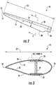
- FIGS. 2 and 3 one of the rotor blades 16 of FIG. 1 is illustrated in accordance with aspects of the present subject matter.
- FIG. 2 illustrates a perspective view of the rotor blade 16
- FIG. 3 illustrates a cross-sectional view of the rotor blade 16 along the sectional line 3-3 shown in FIG. 2 .
- the rotor blade 16 generally includes a blade root 30 configured to be mounted or otherwise secured to the hub 18 ( FIG. 1 ) of the wind turbine 10 and a blade tip 32 disposed opposite the blade root 30.
- a body shell 21 of the rotor blade generally extends between the blade root 30 and the blade tip 32 along a longitudinal axis 27.
- the body shell 21 may generally serve as the outer casing/covering of the rotor blade 16 and may define a substantially aerodynamic profile, such as by defining a symmetrical or cambered airfoil-shaped cross-section.
- the body shell 21 may also define a pressure side 34 and a suction side 36 extending between leading and trailing ends 26, 28 of the rotor blade 16.
- the rotor blade 16 may also have a span 23 defining the total length between the blade root 30 and the blade tip 32 and a chord 25 defining the total length between the leading edge 26 and the trialing edge 28.
- the chord 25 may vary in length with respect to the span 23 as the rotor blade 16 extends from the blade root 30 to the blade tip 32.
- the body shell 21 of the rotor blade 16 may be formed as a single, unitary component.
- the body shell 21 may be formed from a plurality of shell components.
- the body shell 21 may be manufactured from a first shell half generally defining the pressure side 34 of the rotor blade 16 and a second shell half generally defining the suction side 36 of the rotor blade 16, with such shell halves being secured to one another at the leading and trailing ends 26, 28 of the blade 16.
- the body shell 21 may generally be formed from any suitable material.
- the body shell 21 may be formed entirely from a laminate composite material, such as a carbon fiber reinforced laminate composite or a glass fiber reinforced laminate composite.
- one or more portions of the body shell 21 may be configured as a layered construction and may include a core material, formed from a lightweight material such as wood (e.g., balsa), foam (e.g., extruded polystyrene foam) or a combination of such materials, disposed between layers of laminate composite material.
- a core material formed from a lightweight material such as wood (e.g., balsa), foam (e.g., extruded polystyrene foam) or a combination of such materials, disposed between layers of laminate composite material.
- the rotor blade 16 may also include one or more longitudinally extending structural components configured to provide increased stiffness, buckling resistance, and/or strength to the rotor blade 16.
- the rotor blade 16 may include a pair of longitudinally extending spar caps 20, 22 configured to be engaged against the opposing inner surfaces 35, 37 of the pressure and suction sides 34, 36 of the rotor blade 16, respectively.
- one or more shear webs 24 may be disposed between the spar caps 20, 22 so as to form a beam-like configuration.
- the spar caps 20, 22 may generally be designed to control the bending stresses and/or other loads acting on the rotor blade 16 in a generally span-wise direction (a direction parallel to the span 23 of the rotor blade 16) during operation of a wind turbine 10. Similarly, the spar caps 20, 22 may also be designed to withstand the span-wise compression occurring during operation of the wind turbine 10.
- FIGS. 4-7 various views of a spar cap 20 according to the present disclosure are illustrated.
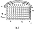
- FIG. 4 illustrates a cross-sectional view of the spar cap 20 secured to the suction side 36 of the body shell 21 of the rotor blade 16.
- FIG. 5 illustrates a perspective span-wise view of the spar cap 20 according to the present disclosure.
- FIG. 6 illustrates a cross-sectional view of the spar cap 20 of FIG. 5 along sectional line 6-6.
- FIG. 7 illustrates a cross-sectional view of the spar cap 20 of FIG. 5 along sectional line 7-7 shown in FIG. 5 .
- the spar cap 20 is constructed of an enclosed primary outer casing 42 having a hollow interior 44 configured to receive a plurality of pultruded rods 40 therein. Further, as shown, the pultruded rods 40 are secured within the hollow interior 44 of the primary outer casing 42 via a first resin material 46.
- the primary outer casing 42 described herein may be constructed of a plurality of fibers joined together via a second resin material 47.
- the hollow interior 44 may extend between a root end 48 and a tip end 50 in a generally span-wise direction. Further, as shown, the spar cap 20 may be curved between the root end 48 and the tip end 50.
- the plurality of pultruded rods 40 are sized to provide flexibility to the spar cap 20 such that the spar cap 20 can conform to the curvature of the rotor blade 16.
- the spar cap 20 may be formed in segments of pultruded rods 40 housed in outer casings 42. More specifically, segments of a spar cap 20 may be joined together using scarf joints or other methods for adhering multiple segments together.
- the pultruded rods 40 may include a first fiber volume fraction of from about 60% to about 80%. More specifically, in certain embodiments, the first fiber volume fraction may be about 69%.
- the combined enclosed primary outer casing 42, the plurality of pultruded rods 40, and the first resin material together may include a second fiber volume fraction of from about 50% to about 70%. More specifically, in certain embodiments, the second fiber volume fraction may be about 58%.
- a fiber volume fraction is generally defined as the ratio of the volume of the fiber strands to the volume of both the fiber strands and resin as a percentage.
- the maximum diameter of each of the plurality of pultruded rods corresponds to a diameter thereof. Further, the diameter of each of the plurality of rods may be less than about 10% of a maximum dimension of the enclosed outer. A used herein, the maximum dimension of the enclosed outer casing is the maximum dimension in the chord-wise direction of the outer casing. In some embodiments, each of the plurality of pultruded rods may have a diameter ranging from about 0.5 mm to about 40 mm. As such, the diameter of each of the pultruded rods 40, which corresponds to the maximum dimension thereof, is configured to maximize the flexibility of the rotor blade component.
- the diameter of the pultruded rods 40 is generally correlated with the fiber volume fraction of the rods 40.
- pultruded rods 40 with larger diameters generally tend to have lower fiber volume fractions.
- pultruded rods 40 with smaller diameters generally tend to have higher fiber volume fractions, which, in regard to flexibility, is favorable.
- pultruded rods 40 of varied diameters may be utilized in forming the rotor blade components described herein in order to achieve the desired fiber volume fraction.
- the hollow interior 44 of the enclosed primary outer casing 42 may vary from the root end 48 to the tip end 50.
- the hollow interior 44 of the enclosed primary outer casing 42 may taper between the root end 48 and the tip end 50. More specifically, as shown particularly in FIGS. 6 and 7 , a cross-sectional area 58 of the hollow interior 44 closer to the blade root 30 may be larger than the cross-sectional area 58 of the hollow interior 44 closer to the blade tip 32.
- the hollow interior 44 of the enclosed primary outer casing 42 may define a wall thickness 56 that varies between the root end 48 to the tip end 50. More specifically, FIG. 6 illustrates the wall thickness 56 closer to the blade root 30 being larger than the thickness 56 closer to the blade tip 32. In still further embodiments, the wall thickness 56 of the outer casing 42 may be constant from the root end 48 to the tip end 50.
- the pultruded rods 40 described herein may be formed using any suitable pultrusion process.
- the pultruded rods 40 are generally formed of reinforced materials (e.g. fibers or woven or braided strands) that are impregnated with a resin material and pulled through a stationary die such that the resin material cures or undergoes polymerization through added heat or other curing methods.
- the heated die may include a mold cavity corresponding to the desired shape of pultruded rods 40 such that the mold cavity forms the desired shape in the completed part.
- the enclosed primary outer casing 42 maybe formed using any suitable process, including but not limited to pultrusion, thermoforming, or infusion.
- the fibers may include but are not limited to glass fibers, nanofibers, carbon fibers, metal fibers, wood fibers, bamboo fibers, polymer fibers, ceramic fibers, or similar.
- the fiber material may include short fibers, long fibers, or continuous fibers.
- thermoplastic material as described herein generally encompasses a plastic material or polymer that is reversible in nature.
- thermoplastic materials typically become pliable or moldable when heated to a certain temperature and solidify upon cooling.
- thermoplastic materials may include amorphous thermoplastic materials and/or semi-crystalline thermoplastic materials.
- some amorphous thermoplastic materials may generally include, but are not limited to, styrenes, vinyls, cellulosics, polyesters, acrylics, polysulphones, and/or imides.
- exemplary amorphous thermoplastic materials may include polystyrene, acrylonitrile butadiene styrene (ABS), polymethyl methacrylate (PMMA), glycolised polyethylene terephthalate (PET-G), polycarbonate, polyvinyl acetate, amorphous polyamide, polyvinyl chlorides (PVC), polyvinylidene chloride, polyurethane, or any other suitable amorphous thermoplastic material.
- exemplary semi-crystalline thermoplastic materials may generally include, but are not limited to polyolefins, polyamides, fluropolymer, ethyl-methyl acrylate, polyesters, polycarbonates, and/or acetals.
- exemplary semi-crystalline thermoplastic materials may include polybutylene terephthalate (PBT), polyethylene terephthalate (PET), polypropylene, polyphenyl sulfide, polyethylene, polyamide (nylon), polyetherketone, or any other suitable semi-crystalline thermoplastic material.
- PBT polybutylene terephthalate
- PET polyethylene terephthalate
- Ppropylene polypropylene
- polyphenyl sulfide polyethylene
- polyamide nylon
- polyetherketone polyetherketone
- thermoset material as described herein generally encompasses a plastic material or polymer that is non-reversible in nature.
- thermoset materials once cured, cannot be easily remolded or returned to a liquid state.
- thermoset materials after initial forming, are generally resistant to heat, corrosion, and/or creep.
- Example thermoset materials may generally include, but are not limited to, some polyesters, esters, epoxies, or any other suitable thermoset material.
- the pultruded rods 40 can be then joined together within the outer casing 42 to form the spar cap 20. More specifically, the pultruded rods 40 may be joined and/or secured together via vacuum infusion, adhesive, semi-preg material, pre-preg material, or any other suitable joining method. In addition, as mentioned, the pultruded rods 40 are arranged in the outer casing 42 so as to maximize the flexibility of the spar cap 20.
- the pultruded rods 40 may have any suitable cross-sectional shape.
- the cross-sectional shape of the pultruded rods 40 may correspond to a generally circular shape.
- the cross-sectional shape of the pultruded rods 40 can be any desirable shape such as, but not limited to, square, rectangular, triangular, octagonal, diamond, or rebar.
- Such embodiments utilizing triangular or rectangular pultruded rods 40 may use a triangular and/or a rectangular packing arrangement respectively.
- pultruded rods 40 of any shape may also be organized in a triangular and/or rectangular packing arrangement, and that more than one packing arrangement may be utilized in the same spar cap.
- the spar cap 20 may include pultruded rods 40 formed of carbon fibers (shaded) and/or glass fibers (non-shaded).
- a ratio of the pultruded rods 40 formed from glass fibers to pultruded rods 40 formed from carbon fibers may vary along the span-wise direction.
- the ratio of pultruded rods 40 formed from glass fibers to pultruded rods 40 formed from carbon fibers is higher at the blade root 30.
- FIG. 6 the ratio of pultruded rods 40 formed from glass fibers to pultruded rods 40 formed from carbon fibers is higher at the blade root 30.
- the ratio of pultruded rods 40 formed from glass fibers to pultruded rods formed 40 from carbon fibers is lower closer to the blade tip 32.
- a change in the ratio of pultruded rods 40 formed from glass fibers to carbon fibers along the span of the rotor blade 16 allows for different properties from the blade root 30 to the blade tip 32.
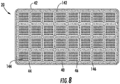
- the illustrated spar cap 20 includes a plurality of enclosed additional enclosed casings 142 arranged within the enclosed primary outer casing 42.
- the additional enclosed casings 142 include additional hollow interiors 144 each configured to receive a portion of the pultruded rods 40.
- the spar cap 20 includes a plurality of additional enclosed casings 142 arranged in a plurality of rows and columns (e.g.
- each additional enclosed casing 142 containing a plurality of pultruded rods 40 arranged therein in a plurality of rows and columns.
- the primary enclosed casing 42 can contain a matrix of horizontal and/or vertical stiffening ribs separating at least some of the additional enclosed casings 142.
- the additional enclosed casings 142 are secured within the hollow interior 44 of the primary outer casing 42 using an additional resin material 146.
- the enclosed additional enclosed casings 142 may also be formed via pultrusion, thermoforming, and/or infusion. It should also be recognized that the enclosed primary outer casing 42, the enclosed additional enclosed casing 142, and/or the pultruded rods 40 of some embodiments are pre-cured, pre-fabricated components manufactured using any suitable methods known in the art.
- the spar cap 20 also includes at least one filler material 52.
- the filler material 52 is received and secured within the enclosed primary outer casing 42 within the hollow interior 44 via the first resin material 46.
- the filler material 52 is centrally located and surrounded by the pultruded rods 40.
- the filler material 52 may be located at any suitable location within the outer casing 42.
- the filler material 52 may include any suitable material, including but not limited to high-density foam, low-density foam, stiffening ribs, a fluid (e.g. air), or other similar materials or fluids known in the art.
- the hollow interior 44 may include a plurality of filler materials 52 arranged therein either together or separately.
- the filler material 52 may include a matrix of horizontal and/or vertical stiffening ribs configured to receive a portion of the pultruded rods in the each of the spaces between stiffening ribs.
- the matrix of vertical and horizontal stiffening ribs may fill the hollow interior 44 with the first resin material 46 and the pultruded rods 40 filling the spaces between stiffening ribs.
- the spar cap 20 may include a plurality of hollow interiors or cavities 54 (rather than just a single hollow interior 44 as shown in FIG. 4 ).
- the illustrated outer casing 42 includes three cavities 54.
- the spar cap 20 may include any number and/or orientation of cavities 54.
- one or more of the cavities 54 may be filled with the pultruded rods 40.
- the enclosed primary outer casing 42 includes a plurality of cavities 54 arranged in a side-by-side configuration in the chord-wise direction with the outer cavities 54 containing pultruded rods 40.
- the center cavity 54 includes a filler material 52 such as those described herein.
- FIG. 10 illustrates an embodiment where the middle cavity 54 is an open cavity (i.e. the cavity 54 contains air).
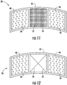
- FIG. 11 illustrates a rotor blade component in which the filler material 52 within the middle cavity 54 corresponds to stiffening ribs.
- the stiffening ribs may also include an additional filler material such as foam arranged therein. Alternatively, the stiffening ribs may be simply filled with air.
- FIG. 12 illustrates rotor blade component in which the filler material 52 within the middle cavity 54 corresponds to a foam material (i.e. without the stiffening ribs).
- the spar cap 22 is the lower spar cap 22 adhered to the pressure side 34 of the body shell 21 as shown in FIG. 3 .
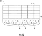
- the spar cap 22 can further include at least one pultruded plate 41.
- the at least one pultruded plate 41 can be joined with the exterior of the primary outer casing 42 and secured therein via a third resin material (not shown).
- the pultruded plates 41 may be joined and/or secured together and/or to the primary outer casing 42 via vacuum infusion, adhesive, semi-preg material, pre-preg material, or any other suitable joining method.
- the spar cap 22 may include a plurality of pultruded plates 41 joined together and with the exterior of the primary outer casing 42.
- the pultruded plates 41 may be received and secured within the hollow interior 44 of the primary outer casing 42 using the first resin material 46.
- the present disclosure is also directed to methods for manufacturing rotor blade components as described herein.
- a flow diagram of one embodiment of a method 100 of manufacturing a rotor blade component of the wind turbine 10 is disclosed.
- the method 100 includes providing an enclosed outer casing 42.
- the method 100 includes arranging a plurality of pultruded rods 40 within the outer casing 42 in a plurality of rows and columns. More specifically, an arrangement of the pultruded rods 40 within the outer casing 42 and a maximum dimension of the pultruded rods 40 are configured to maximize the flexibility of the rotor blade component.
- the method 100 also includes sealing the outer casing 42 at opposing ends thereof.
- the method 100 includes infusing at least one resin material into the outer casing 42 to secure the pultruded rods 40 therein so as to form the rotor blade component.
- the plurality of pultruded rods 40, the primary outer casing 42, and the additional casings 142 as described herein may be used to construct various other rotor blade components, in addition to spar caps.
- the components and methods described herein may be used to construct the shear web 24, a root ring, an edgewise stiffening reinforcement, or any other rotor blade component that can benefit from being constructed of pultruded parts as described herein.
Landscapes
- Engineering & Computer Science (AREA)
- Life Sciences & Earth Sciences (AREA)
- Mechanical Engineering (AREA)
- Chemical & Material Sciences (AREA)
- Sustainable Energy (AREA)
- Combustion & Propulsion (AREA)
- Sustainable Development (AREA)
- General Engineering & Computer Science (AREA)
- Wood Science & Technology (AREA)
- Physics & Mathematics (AREA)
- Fluid Mechanics (AREA)
- Composite Materials (AREA)
- Wind Motors (AREA)
- Moulding By Coating Moulds (AREA)
- Extrusion Moulding Of Plastics Or The Like (AREA)
Abstract
Description
- The present subject matter relates generally to wind turbine rotor blades of and, more particularly, to wind turbine rotor blade components formed using pultruded rods.
- Wind power is considered one of the cleanest, most environmentally friendly energy sources presently available, and wind turbines have gained increased attention in this regard. A modern wind turbine typically includes a tower, generator, gearbox, nacelle, and one or more rotor blades. The rotor blades capture kinetic energy from wind using known foil principles and transmit the kinetic energy through rotational energy to turn a shaft coupling the rotor blades to a gearbox, or if a gearbox is not used, directly to the generator. The generator then converts the mechanical energy to electrical energy that may be deployed to a utility grid.
- Wind turbine rotor blades generally include a body shell formed by two shell halves of a composite laminate material. The shell halves are generally manufactured using molding processes and then coupled together along the corresponding ends of the rotor blade. In general, the body shell is relatively lightweight and has structural properties (e.g., stiffness, buckling resistance, and strength) which are not configured to withstand the bending moments and other loads exerted on the rotor blade during operation. In addition, wind turbine blades are becoming increasingly longer in order to produce more power. As a result, the blades must be stiffer and thus heavier so as to mitigate loads on the rotor.
- To increase the stiffness, buckling resistance, and strength of the rotor blade, the body shell is typically reinforced using one or more structural components (e.g. opposing spar caps with a shear web configured therebetween) that engage the inner surfaces of the shell halves. The spar caps may be constructed of various materials, including but not limited to glass fiber laminate composites and/or carbon fiber laminate composites. Such materials, however, can be difficult to control, defect prone, and/or highly labor intensive due to handling of the dry and pre-preg fabrics and the challenges of infusing large laminated structures.
- As such, spar caps may also be constructed of pre-fabricated, pre-cured (i.e. pultruded) composites that can be produced in thicker sections, and are less susceptible to defects. In addition, the use of pultrusions in spar caps can decrease the weight thereof and may also increase the strength thereof. Accordingly, the pultruded composites can eliminate various concerns and challenges associated with using dry fabric alone. As used herein, the terms "pultruded composites," "pultrusions," "pultruded members" or similar generally encompass reinforced materials (e.g. fibers or woven or braided strands) that are impregnated with a resin and pulled through a stationary die such that the resin cures or undergoes polymerization through added heat or other curing methods. As such, the process of manufacturing pultruded composites is typically characterized by a continuous process of composite materials that produces composite parts having a constant cross-section. A plurality of pultrusions can then be joined together to form the spar caps and/or various other rotor blade components.
- Thus, spar caps formed using pultrusions usually include pultrusion-formed layers bonded together via a resin material. More specifically, spar caps are generally formed of a plurality of stacked pultruded plates that are bonded together in a mold.
- Though the benefits of using pultruded plates in spar caps have been realized, inherent properties of such plates or layers present design challenges. For example, using plate-shaped pultrusions to form curved-shaped components. More specifically, many pultrusions have a flat cross-section (e.g. are square or rectangular) as such shapes are easy to manufacture. Though the use of flat pultrusions can offer a significant improvement in cost and producibility of rotor blade components, such pultrusions do not typically lay into curved molds without gaps between the pultrusions and the mold shape. Since wind turbine blades are often curved from root to tip, challenges exist to form pultruded layers that curve with the blade shell. When plates containing different fibers are utilized in the same component, modulus mismatch can become problematic. For instance, substantial differences in the elastic modulus between plates can cause delamination to occur between the plates.
- Conformance to the mold can be achieved to a certain degree by cutting the pultrusions into thinner strips; however, this increases the cost of the pultrusion process, machining time, and/or the difficulty of placing the pultrusions into the mold. In addition, the use of pultruded layers creates a concern for crack propagation. More specifically, cracks in a pultruded layer tend to migrate from end to end in a relatively short amount of time.
- Accordingly, the art is continuously seeking new and improved methods of manufacturing rotor blade components, such as spar caps, using pultrusions. More specifically, methods of manufacturing rotor blade components using pultruded rods that provide more flexibility to the component such that the component can adhere to curved surfaces of the rotor blade would be advantageous. A crack in a rotor blade component utilizing pultruded rods tends to move in a zig-zag manner around the pultruded rods, which leads to a longer propagation life.
- Various aspects and advantages of the invention will be set forth in part in the following description, or may be clear from the description, or may be learned through practice of the invention.
- In one aspect, the present disclosure is directed to a rotor blade component for a wind turbine. The rotor blade component includes an enclosed primary outer casing and a plurality of pultruded rods. The enclosed primary outer casing defines a hollow interior. The plurality of pultruded rods is received within the hollow interior of the primary outer casing and secured therein via a first resin material. Further, an arrangement of the plurality of pultruded rods within the primary outer casing and a relationship of a maximum dimension of each of the plurality of pultruded rods and a maximum dimension of the enclosed primary outer casing are configured to maximize flexibility of the rotor blade component.
- In one embodiment, the plurality of pultruded rods may include a first fiber volume fraction of from about 60% to about 80%. In another embodiment, primary outer casing, the plurality of pultruded rods, and the first resin material together may include a second fiber volume fraction of from about 50% to about 70%. In other embodiments, the maximum diameter of each of the plurality of pultruded rods corresponds to a diameter thereof. Further, the diameter of each of the plurality of pultruded rods may be less than about 10% of a maximum dimension of the enclosed outer casing. More specifically, in one embodiment, the diameter of each of the plurality of pultruded rods may range from about 0.5 millimeters (mm) to about 40 mm. In a further embodiment the enclosed primary outer casing may be constructed of a plurality of fibers joined together via a second resin material.
- In additional embodiments, the primary outer casing may include a root end and a tip end, the enclosed primary outer casing being curved between said root end and said tip end. In one embodiment, a cross-sectional area of the primary outer casing may taper between the root end and the tip end. Still, in a further embodiment, the primary outer casing may define a wall thickness that varies between the root end to the tip end.
- In further embodiments, a plurality of enclosed additional enclosed casings may be arranged within the primary outer casing. At least a portion of the plurality of rods is received within each of the enclosed additional enclosed casings. In another embodiment, the rotor blade component may include a filler material received and secured within the enclosed primary outer casing via the first resin material.
- In yet another embodiment, the primary outer casing may include a plurality of cavities arranged in a side-by-side configuration in a chord-wise direction of the rotor blade. At least two of the plurality of cavities includes at least a portion of the plurality of pultruded rods and at least one of the plurality of cavities includes a filler material.
- In a further embodiment, the rotor blade component may further include at least one pultruded plate. The pultruded plate may be joined with the exterior of the primary outer casing and secured there via a third resin material.
- In another aspect, the present disclosure is directed to a rotor blade assembly for a wind turbine. The rotor blade assembly includes a rotor blade. The rotor blade includes a suction side, a pressure side, a leading edge, and a trailing edge extending between a blade root and a blade tip. The rotor blade assembly also includes at least one rotor blade component arranged within the rotor blade. The rotor blade component includes an enclosed primary outer casing extending in a span-wise direction of the rotor blade from the blade root towards the blade tip. The enclosed primary outer casing includes at least one cavity and a plurality of pultruded rods. The plurality of pultruded rods is received and secured within the at least one cavity via a first resin material. An arrangement of the plurality of pultruded rods within the primary outer casing and a relationship of a maximum dimension of each of the plurality of pultruded rods and a maximum dimension of the enclosed primary outer casing are configured to maximize flexibility of the rotor blade component.
- In additional embodiments, the plurality of pultruded rods may include at least one of carbon or glass fibers. A ratio of pultruded rods formed from glass fibers to pultruded rods formed from carbon fibers may vary along the span-wise direction.
- In a further embodiment, the rotor blade assembly may include a plurality of enclosed additional enclosed casings arranged within the primary outer casing. At least a portion of the plurality of rods is received within each of the enclosed additional enclosed casings. In another embodiment, the enclosed primary outer casing may include a plurality of cavities arranged in a side-by-side configuration in a chord-wise direction of the rotor blade.
- In yet another aspect, the present disclosure is directed to a method of manufacturing a rotor blade component of a wind turbine. The method includes providing an enclosed outer casing. Another step includes arranging a plurality of pultruded rods within the enclosed outer casing in a plurality of rows and columns. An arrangement of the plurality of pultruded rods within the primary outer casing and a relationship of a maximum dimension of each of the plurality of pultruded rods and a maximum dimension of the enclosed primary outer casing are configured to maximize flexibility of the rotor blade component. Yet another step includes sealing the outer casing at opposing ends thereof. The method also includes infusing at least one resin material into the outer casing to secure the plurality of pultruded rods therein so as to form the rotor blade component.
- In other embodiments, the rotor blade component may include at least one of a spar cap, a shear web, a root ring, or an edgewise stiffening reinforcement. Still in further embodiments, the enclosed primary outer casing may be formed via at least one of pultrusion, thermoforming, or infusion.
- Various features, aspects, and advantages of the present invention will become better understood with reference to the following description and appended claims. The accompanying drawings, which are incorporated in and constitute a part of this specification, illustrate embodiments of the invention and, together with the description, serve to explain the principles of the invention.
- in the drawings:
-
FIG. 1 illustrates a perspective view of one embodiment of a wind turbine according to the present disclosure; -
FIG. 2 illustrates a perspective view of one of the rotor blades ofFIG. 1 ; -
FIG. 3 illustrates a cross-sectional view of the rotor blade ofFIG. 2 along line 3 -3; -
FIG. 4 illustrates a cross-sectional view of one embodiment of a pultruded spar cap formed using pultruded rods according to the present disclosure; -
FIG. 5 illustrates a perspective, span-wise view of one embodiment of a spar cap formed using pultruded rods according to the present disclosure; -
FIG. 6 illustrates a cross-sectional view of the spar cap ofFIG. 5 along section line 6-6; -
FIG. 7 illustrates another cross-sectional view of the spar cap ofFIG. 5 along section line 7-7; -
FIG. 8 illustrates a chord-wise view of a one embodiment of a spar cap according to the present disclosure, particularly illustrating a spar cap having an enclosed primary outer casing and multiple enclosed additional enclosed outer casings arranged therein with a plurality of pultruded rods arranged within each of the enclosed additional enclosed casings; -
FIG 9 . illustrates one embodiment of a spar cap according to the present disclosure, particularly illustrating a spar cap containing a filler material arranged within an enclosed primary outer casing and a plurality of pultruded rods arranged around the filler material; -
FIG 10 . illustrates a chord-wise view of one embodiment of a spar cap according to the present disclosure, particularly illustrating a spar cap having a plurality of cavities arranged in a side-by-side configuration with a plurality of pultruded rods contained within two of the cavities and an open middle cavity; -
FIG. 11 illustrates a chord-wise view of one embodiment of a spar cap according to the present disclosure, particularly illustrating a spar cap having a plurality of cavities arranged in a side-by-side configuration with a plurality of pultruded rods contained within two of the cavities and a plurality of stiffening rods contained within a middle cavity; -
FIG. 12 illustrates a chord-wise view of one embodiment of a spar cap according to the present disclosure, particularly illustrating a spar cap having a plurality of cavities arranged in a side-by-side configuration with a plurality of pultruded rods contained within two of the cavities and a filler material contained within a middle cavity; -
FIG. 13 illustrates a chord-wise view of one embodiment of a spar cap according to the present disclosure, particularly illustrating a spar cap having a plurality of pultruded plates joined with an outer casing filled with a plurality of pultruded rods; and -
FIG. 14 illustrates a flow diagram of one embodiment of a method of manufacturing rotor blade components according to the present disclosure. - Reference now will be made in detail to embodiments of the invention, one or more examples of which are illustrated in the drawings. Each example is provided by way of explanation of the invention, not limitation of the invention. In fact, it will be apparent to those skilled in the art that various modifications and variations can be made in the present invention without departing from the scope or spirit of the invention. For instance, features illustrated or described as part of one embodiment can be used with another embodiment to yield a still further embodiment. Thus, it is intended that the present invention covers such modifications and variations as come within the scope of the appended claims and their equivalents.
- Generally, the present subject matter is directed to improved pultruded rotor blade components for wind turbines and methods of manufacturing the same. For example, in one embodiment, the rotor blade components described herein may be formed using a plurality of pultruded rods arranged in an enclosed primary outer casing. The enclosed primary outer casing defines a hollow interior extending between a root end and an opposing tip end. Each of the plurality of pultruded rods is received within the enclosed primary outer casing and secured therein via a first resin material. As such, the outer casing acts as both the component mold and part of the finished part. Further, an arrangement of the plurality of pultruded rods within the enclosed primary outer casing and a maximum dimension of the pultruded rods are configured to maximize the flexibility of the rotor blade component.
- As such, flexibility of the part can be adjusted by changing the number of pultruded rods, the cross-sectional area of the pultruded rods, the fiber volume fraction of the pultruded rods, and/or the ratio of the cross-sectional area of the pultruded rods to the hollow cross-sectional area of the enclosed primary outer casing.
- The present disclosure provides many advantages not present in the prior art. For example, the use of pultruded materials in spar caps and other rotor blade components can reduce defects and increase the strength of the component. Further, rotor blade components of the present disclosure that are formed via pultruded rods are more flexible (as compared to pultruded plates) and therefore more capable of conforming to a curved cavity that can be better incorporated into a curved rotor blade mold. Moreover, rotor blade components of the present invention can have better crack propagation characteristics versus a pultruded plate. In addition, components utilizing rods containing different fibers can avoid the delamination issue possible with plates formed from different fibers. More specifically, the smaller shape and geometry of the rods can prevent extreme modulus jumps that can lead to delamination.
- Referring now to the drawings,
FIG. 1 illustrates a perspective view of a horizontalaxis wind turbine 10. It should be appreciated that thewind turbine 10 may also be a vertical-axis wind turbine. As shown in the illustrated embodiment, thewind turbine 10 includes atower 12, anacelle 14 mounted on thetower 12, and arotor hub 18 that is coupled to thenacelle 14. Thetower 12 may be fabricated from tubular steel or other suitable material. Therotor hub 18 includes one ormore rotor blades 16 coupled to and extending radially outward from thehub 18. As shown, therotor hub 18 includes threerotor blades 16. However, in an alternative embodiment, therotor hub 18 may include more or less than threerotor blades 16. Therotor blades 16 rotate therotor hub 18 to enable kinetic energy to be transferred from the wind into usable mechanical energy, and subsequently, electrical energy. Specifically, thehub 18 may be rotatably coupled to an electric generator (not illustrated) positioned within thenacelle 14 for production of electrical energy. - Referring to
FIGS. 2 and 3 , one of therotor blades 16 ofFIG. 1 is illustrated in accordance with aspects of the present subject matter. In particular,FIG. 2 illustrates a perspective view of therotor blade 16, whereasFIG. 3 illustrates a cross-sectional view of therotor blade 16 along the sectional line 3-3 shown inFIG. 2 . As shown, therotor blade 16 generally includes ablade root 30 configured to be mounted or otherwise secured to the hub 18 (FIG. 1 ) of thewind turbine 10 and ablade tip 32 disposed opposite theblade root 30. Abody shell 21 of the rotor blade generally extends between theblade root 30 and theblade tip 32 along alongitudinal axis 27. Thebody shell 21 may generally serve as the outer casing/covering of therotor blade 16 and may define a substantially aerodynamic profile, such as by defining a symmetrical or cambered airfoil-shaped cross-section. Thebody shell 21 may also define apressure side 34 and asuction side 36 extending between leading and trailing ends 26, 28 of therotor blade 16. Further, therotor blade 16 may also have aspan 23 defining the total length between theblade root 30 and theblade tip 32 and achord 25 defining the total length between theleading edge 26 and the trialingedge 28. As is generally understood, thechord 25 may vary in length with respect to thespan 23 as therotor blade 16 extends from theblade root 30 to theblade tip 32. - In several embodiments, the
body shell 21 of therotor blade 16 may be formed as a single, unitary component. Alternatively, thebody shell 21 may be formed from a plurality of shell components. For example, thebody shell 21 may be manufactured from a first shell half generally defining thepressure side 34 of therotor blade 16 and a second shell half generally defining thesuction side 36 of therotor blade 16, with such shell halves being secured to one another at the leading and trailing ends 26, 28 of theblade 16. Additionally, thebody shell 21 may generally be formed from any suitable material. For instance, in one embodiment, thebody shell 21 may be formed entirely from a laminate composite material, such as a carbon fiber reinforced laminate composite or a glass fiber reinforced laminate composite. Alternatively, one or more portions of thebody shell 21 may be configured as a layered construction and may include a core material, formed from a lightweight material such as wood (e.g., balsa), foam (e.g., extruded polystyrene foam) or a combination of such materials, disposed between layers of laminate composite material. - Referring particularly to
FIG. 3 , therotor blade 16 may also include one or more longitudinally extending structural components configured to provide increased stiffness, buckling resistance, and/or strength to therotor blade 16. For example, therotor blade 16 may include a pair of longitudinally extending spar caps 20, 22 configured to be engaged against the opposinginner surfaces suction sides rotor blade 16, respectively. Additionally, one ormore shear webs 24 may be disposed between the spar caps 20, 22 so as to form a beam-like configuration. The spar caps 20, 22 may generally be designed to control the bending stresses and/or other loads acting on therotor blade 16 in a generally span-wise direction (a direction parallel to thespan 23 of the rotor blade 16) during operation of awind turbine 10. Similarly, the spar caps 20, 22 may also be designed to withstand the span-wise compression occurring during operation of thewind turbine 10. - Referring now to
FIGS. 4-7 , various views of aspar cap 20 according to the present disclosure are illustrated. In particular,FIG. 4 illustrates a cross-sectional view of thespar cap 20 secured to thesuction side 36 of thebody shell 21 of therotor blade 16.FIG. 5 illustrates a perspective span-wise view of thespar cap 20 according to the present disclosure.FIG. 6 illustrates a cross-sectional view of thespar cap 20 ofFIG. 5 along sectional line 6-6.FIG. 7 illustrates a cross-sectional view of thespar cap 20 ofFIG. 5 along sectional line 7-7 shown inFIG. 5 . - More specifically, as shown, the
spar cap 20 is constructed of an enclosed primaryouter casing 42 having ahollow interior 44 configured to receive a plurality ofpultruded rods 40 therein. Further, as shown, thepultruded rods 40 are secured within thehollow interior 44 of the primaryouter casing 42 via afirst resin material 46. In addition, the primaryouter casing 42 described herein may be constructed of a plurality of fibers joined together via asecond resin material 47. Moreover, as shown particularly inFIG. 4 , thehollow interior 44 may extend between aroot end 48 and atip end 50 in a generally span-wise direction. Further, as shown, thespar cap 20 may be curved between theroot end 48 and thetip end 50. As such, the plurality ofpultruded rods 40 are sized to provide flexibility to thespar cap 20 such that thespar cap 20 can conform to the curvature of therotor blade 16. In other embodiments, thespar cap 20 may be formed in segments ofpultruded rods 40 housed inouter casings 42. More specifically, segments of aspar cap 20 may be joined together using scarf joints or other methods for adhering multiple segments together. - In some embodiments, the
pultruded rods 40 may include a first fiber volume fraction of from about 60% to about 80%. More specifically, in certain embodiments, the first fiber volume fraction may be about 69%. In further embodiments, the combined enclosed primaryouter casing 42, the plurality ofpultruded rods 40, and the first resin material together may include a second fiber volume fraction of from about 50% to about 70%. More specifically, in certain embodiments, the second fiber volume fraction may be about 58%. As used herein, a fiber volume fraction is generally defined as the ratio of the volume of the fiber strands to the volume of both the fiber strands and resin as a percentage. - In other embodiments, the maximum diameter of each of the plurality of pultruded rods corresponds to a diameter thereof. Further, the diameter of each of the plurality of rods may be less than about 10% of a maximum dimension of the enclosed outer. A used herein, the maximum dimension of the enclosed outer casing is the maximum dimension in the chord-wise direction of the outer casing. In some embodiments, each of the plurality of pultruded rods may have a diameter ranging from about 0.5 mm to about 40 mm. As such, the diameter of each of the
pultruded rods 40, which corresponds to the maximum dimension thereof, is configured to maximize the flexibility of the rotor blade component. For example, the diameter of thepultruded rods 40 is generally correlated with the fiber volume fraction of therods 40. As such, pultrudedrods 40 with larger diameters generally tend to have lower fiber volume fractions. In contrast, pultrudedrods 40 with smaller diameters generally tend to have higher fiber volume fractions, which, in regard to flexibility, is favorable. Furthermore, in certain embodiments, pultrudedrods 40 of varied diameters may be utilized in forming the rotor blade components described herein in order to achieve the desired fiber volume fraction. - Referring now generally to
FIGS. 5-7 , in certain embodiments, thehollow interior 44 of the enclosed primaryouter casing 42 may vary from theroot end 48 to thetip end 50. For example, as shown inFIG. 5 , thehollow interior 44 of the enclosed primaryouter casing 42 may taper between theroot end 48 and thetip end 50. More specifically, as shown particularly inFIGS. 6 and 7 , across-sectional area 58 of thehollow interior 44 closer to theblade root 30 may be larger than thecross-sectional area 58 of thehollow interior 44 closer to theblade tip 32. - In addition, as shown particularly in
FIGS. 5-7 , thehollow interior 44 of the enclosed primaryouter casing 42 may define awall thickness 56 that varies between theroot end 48 to thetip end 50. More specifically,FIG. 6 illustrates thewall thickness 56 closer to theblade root 30 being larger than thethickness 56 closer to theblade tip 32. In still further embodiments, thewall thickness 56 of theouter casing 42 may be constant from theroot end 48 to thetip end 50. - It should be understood that the
pultruded rods 40 described herein may be formed using any suitable pultrusion process. For example, thepultruded rods 40 are generally formed of reinforced materials (e.g. fibers or woven or braided strands) that are impregnated with a resin material and pulled through a stationary die such that the resin material cures or undergoes polymerization through added heat or other curing methods. For example, in certain embodiments, the heated die may include a mold cavity corresponding to the desired shape ofpultruded rods 40 such that the mold cavity forms the desired shape in the completed part. Similarly, the enclosed primaryouter casing 42 maybe formed using any suitable process, including but not limited to pultrusion, thermoforming, or infusion. - As such, in various embodiments, the fibers may include but are not limited to glass fibers, nanofibers, carbon fibers, metal fibers, wood fibers, bamboo fibers, polymer fibers, ceramic fibers, or similar. In addition, the fiber material may include short fibers, long fibers, or continuous fibers.
- Further, the resin materials described herein may include a thermoplastic material or a thermoset material. A thermoplastic material as described herein generally encompasses a plastic material or polymer that is reversible in nature. For example, thermoplastic materials typically become pliable or moldable when heated to a certain temperature and solidify upon cooling. Further, thermoplastic materials may include amorphous thermoplastic materials and/or semi-crystalline thermoplastic materials. For example, some amorphous thermoplastic materials may generally include, but are not limited to, styrenes, vinyls, cellulosics, polyesters, acrylics, polysulphones, and/or imides. More specifically, exemplary amorphous thermoplastic materials may include polystyrene, acrylonitrile butadiene styrene (ABS), polymethyl methacrylate (PMMA), glycolised polyethylene terephthalate (PET-G), polycarbonate, polyvinyl acetate, amorphous polyamide, polyvinyl chlorides (PVC), polyvinylidene chloride, polyurethane, or any other suitable amorphous thermoplastic material. In addition, exemplary semi-crystalline thermoplastic materials may generally include, but are not limited to polyolefins, polyamides, fluropolymer, ethyl-methyl acrylate, polyesters, polycarbonates, and/or acetals. More specifically, exemplary semi-crystalline thermoplastic materials may include polybutylene terephthalate (PBT), polyethylene terephthalate (PET), polypropylene, polyphenyl sulfide, polyethylene, polyamide (nylon), polyetherketone, or any other suitable semi-crystalline thermoplastic material.
- Further, a thermoset material as described herein generally encompasses a plastic material or polymer that is non-reversible in nature. For example, thermoset materials, once cured, cannot be easily remolded or returned to a liquid state. As such, after initial forming, thermoset materials are generally resistant to heat, corrosion, and/or creep. Example thermoset materials may generally include, but are not limited to, some polyesters, esters, epoxies, or any other suitable thermoset material.
- Thus, in accordance with certain aspects of the present disclosure, the
pultruded rods 40 can be then joined together within theouter casing 42 to form thespar cap 20. More specifically, thepultruded rods 40 may be joined and/or secured together via vacuum infusion, adhesive, semi-preg material, pre-preg material, or any other suitable joining method. In addition, as mentioned, thepultruded rods 40 are arranged in theouter casing 42 so as to maximize the flexibility of thespar cap 20. - In addition, it should be understood that the
pultruded rods 40 may have any suitable cross-sectional shape. For example, as can be seen inFIG. 4 , the cross-sectional shape of thepultruded rods 40 may correspond to a generally circular shape. In further embodiments, it should be recognized by those in the art that the cross-sectional shape of thepultruded rods 40 can be any desirable shape such as, but not limited to, square, rectangular, triangular, octagonal, diamond, or rebar. Such embodiments utilizing triangular or rectangularpultruded rods 40 may use a triangular and/or a rectangular packing arrangement respectively. It should be recognized that pultrudedrods 40 of any shape may also be organized in a triangular and/or rectangular packing arrangement, and that more than one packing arrangement may be utilized in the same spar cap. - Referring particularly to
FIGS. 6 and 7 , thespar cap 20 may include pultrudedrods 40 formed of carbon fibers (shaded) and/or glass fibers (non-shaded). As such, in certain embodiments, a ratio of thepultruded rods 40 formed from glass fibers topultruded rods 40 formed from carbon fibers may vary along the span-wise direction. For example, as can be seen inFIG. 6 , the ratio ofpultruded rods 40 formed from glass fibers topultruded rods 40 formed from carbon fibers is higher at theblade root 30. In contrast, as shown inFIG. 7 , the ratio ofpultruded rods 40 formed from glass fibers to pultruded rods formed 40 from carbon fibers is lower closer to theblade tip 32. As such, a change in the ratio ofpultruded rods 40 formed from glass fibers to carbon fibers along the span of therotor blade 16 allows for different properties from theblade root 30 to theblade tip 32. - Referring now to
FIG. 8 , another embodiment of aspar cap 20 formed frompultruded rods 40 according to the present disclosure is illustrated. More specifically, as shown, the illustratedspar cap 20 includes a plurality of enclosed additionalenclosed casings 142 arranged within the enclosed primaryouter casing 42. Thus, as shown, the additionalenclosed casings 142 include additionalhollow interiors 144 each configured to receive a portion of thepultruded rods 40. For example, as shown, thespar cap 20 includes a plurality of additionalenclosed casings 142 arranged in a plurality of rows and columns (e.g. a 4 x 8 matrix) with each additionalenclosed casing 142 containing a plurality ofpultruded rods 40 arranged therein in a plurality of rows and columns. In another embodiment, the primaryenclosed casing 42 can contain a matrix of horizontal and/or vertical stiffening ribs separating at least some of the additionalenclosed casings 142. - Further, as shown, the additional
enclosed casings 142 are secured within thehollow interior 44 of the primaryouter casing 42 using anadditional resin material 146. Like the primaryouter casing 42, the enclosed additionalenclosed casings 142 may also be formed via pultrusion, thermoforming, and/or infusion. It should also be recognized that the enclosed primaryouter casing 42, the enclosed additionalenclosed casing 142, and/or thepultruded rods 40 of some embodiments are pre-cured, pre-fabricated components manufactured using any suitable methods known in the art. - Referring now to
FIG. 9 , still another embodiment of aspar cap 20 formed from the primaryouter casing 42 and thepultruded rods 40 according to the present disclosure is illustrated. More specifically, as shown, thespar cap 20 also includes at least onefiller material 52. For example, as shown, thefiller material 52 is received and secured within the enclosed primaryouter casing 42 within thehollow interior 44 via thefirst resin material 46. In addition, as shown in the illustrated embodiment, thefiller material 52 is centrally located and surrounded by thepultruded rods 40. In alternative embodiments, thefiller material 52 may be located at any suitable location within theouter casing 42. Further, thefiller material 52 may include any suitable material, including but not limited to high-density foam, low-density foam, stiffening ribs, a fluid (e.g. air), or other similar materials or fluids known in the art. In another embodiment, thehollow interior 44 may include a plurality offiller materials 52 arranged therein either together or separately. - In a further embodiment the
filler material 52 may include a matrix of horizontal and/or vertical stiffening ribs configured to receive a portion of the pultruded rods in the each of the spaces between stiffening ribs. For example, the matrix of vertical and horizontal stiffening ribs may fill thehollow interior 44 with thefirst resin material 46 and thepultruded rods 40 filling the spaces between stiffening ribs. - Referring now to
FIGS. 10-12 , further embodiments of rotor blades components formed from the primaryouter casing 42 and thepultruded rods 40 according to the present disclosure is illustrated. More specifically, as shown, thespar cap 20 may include a plurality of hollow interiors or cavities 54 (rather than just a singlehollow interior 44 as shown inFIG. 4 ). For example, as shown, the illustratedouter casing 42 includes threecavities 54. Further, it should be recognized that thespar cap 20 may include any number and/or orientation ofcavities 54. - As such, one or more of the
cavities 54 may be filled with thepultruded rods 40. For example, as shown particularly inFIG. 10 , the enclosed primaryouter casing 42 includes a plurality ofcavities 54 arranged in a side-by-side configuration in the chord-wise direction with theouter cavities 54 containing pultrudedrods 40. In addition, as shown, thecenter cavity 54 includes afiller material 52 such as those described herein. In particular,FIG. 10 illustrates an embodiment where themiddle cavity 54 is an open cavity (i.e. thecavity 54 contains air). Such anopen cavity 54 can be used as a conduit for power cables, an actuating medium (such as pressurized air) to operate active and/or passive devices, down conductor conduits to prevent damage from lighting, and/or hot air to heat therotor blade 16. In contrast,FIG. 11 illustrates a rotor blade component in which thefiller material 52 within themiddle cavity 54 corresponds to stiffening ribs. In such embodiments, the stiffening ribs may also include an additional filler material such as foam arranged therein. Alternatively, the stiffening ribs may be simply filled with air. In still another embodiment,FIG. 12 illustrates rotor blade component in which thefiller material 52 within themiddle cavity 54 corresponds to a foam material (i.e. without the stiffening ribs). - Referring now to
FIG. 13 , a further embodiment of aspar cap 22 formed from the primaryouter casing 42, pultrudedrods 40, and pultrudedplates 41 according to the present disclosure is illustrated. More specifically, in this embodiment thespar cap 22 is thelower spar cap 22 adhered to thepressure side 34 of thebody shell 21 as shown inFIG. 3 . As shown, thespar cap 22 can further include at least onepultruded plate 41. The at least onepultruded plate 41 can be joined with the exterior of the primaryouter casing 42 and secured therein via a third resin material (not shown). More specifically, thepultruded plates 41 may be joined and/or secured together and/or to the primaryouter casing 42 via vacuum infusion, adhesive, semi-preg material, pre-preg material, or any other suitable joining method. In some embodiments, as shown inFIG. 13 , thespar cap 22 may include a plurality ofpultruded plates 41 joined together and with the exterior of the primaryouter casing 42. In a different embodiment, thepultruded plates 41 may be received and secured within thehollow interior 44 of the primaryouter casing 42 using thefirst resin material 46. - The present disclosure is also directed to methods for manufacturing rotor blade components as described herein. For example, as shown in
FIG. 14 , a flow diagram of one embodiment of amethod 100 of manufacturing a rotor blade component of thewind turbine 10 is disclosed. As shown at 102, themethod 100 includes providing an enclosedouter casing 42. As shown at 104, themethod 100 includes arranging a plurality ofpultruded rods 40 within theouter casing 42 in a plurality of rows and columns. More specifically, an arrangement of thepultruded rods 40 within theouter casing 42 and a maximum dimension of thepultruded rods 40 are configured to maximize the flexibility of the rotor blade component. As shown at 106, themethod 100 also includes sealing theouter casing 42 at opposing ends thereof. As shown at 108, themethod 100 includes infusing at least one resin material into theouter casing 42 to secure thepultruded rods 40 therein so as to form the rotor blade component. - It should also be understood that the plurality of
pultruded rods 40, the primaryouter casing 42, and theadditional casings 142 as described herein may be used to construct various other rotor blade components, in addition to spar caps. For example, in certain embodiments, the components and methods described herein may be used to construct theshear web 24, a root ring, an edgewise stiffening reinforcement, or any other rotor blade component that can benefit from being constructed of pultruded parts as described herein. - This written description uses examples to disclose the invention, including the best mode, and also to enable any person skilled in the art to practice the invention, including making and using any devices or systems and performing any incorporated methods. The patentable scope of the invention is defined by the claims, and may include other examples that occur to those skilled in the art. Such other examples are intended to be within the scope of the claims if they include structural elements that do not differ from the literal language of the claims, or if they include equivalent structural elements with insubstantial differences from the literal languages of the claims.
- Various aspects and embodiments of the present invention are defined by the following numbered clauses:
- 1. A rotor blade component for a wind turbine, the rotor blade component comprising:
- an enclosed primary outer casing defining a hollow interior; and,
- a plurality of pultruded rods received within the hollow interior of the primary outer casing and secured therein via a first resin material,
- wherein an arrangement of the plurality of pultruded rods within the primary outer casing and a relationship of a maximum dimension of each of the plurality of pultruded rods and a maximum dimension of the enclosed primary outer casing are configured to maximize flexibility of the rotor blade component.
- 2. The rotor blade component of clause 1, wherein each of the plurality of pultruded rods comprises a first fiber volume fraction of from about 60% to about 80%.
- 3. The rotor blade component of any preceding clause, wherein the primary outer casing, the plurality of pultruded rods, and the first resin material together comprise a second fiber volume fraction of from about 50% to about 70%.
- 4. The rotor blade component of any preceding clause, wherein the maximum diameter of each of the plurality of pultruded rods corresponds to a diameter thereof, the diameter of each of the plurality of pultruded rods being less than about 10% of the maximum dimension of the enclosed outer casing.
- 5. The rotor blade component of any preceding clause, wherein the enclosed primary outer casing is constructed of a plurality of fibers joined together via a second resin material.
- 6. The rotor blade component of any preceding clause, wherein the primary outer casing comprises a root end and a tip end, the enclosed primary outer casing being curved between said root end and said tip end.
- 7. The rotor blade component of any preceding clause, wherein a cross-sectional area of the primary outer casing tapers between said root end and said tip end.
- 8. The rotor blade component of any preceding clause, wherein the primary outer casing defines a wall thickness that varies between said root end to said tip end.
- 9. The rotor blade component of any preceding clause, further comprising a plurality of enclosed additional enclosed casings arranged within the primary outer casing, wherein at least a portion of the plurality of rods is received within each of the enclosed additional enclosed casings.
- 10. The rotor blade component of any preceding clause, further comprising a filler material received and secured within the enclosed primary outer casing via the first resin material.
- 11. The rotor blade component of any preceding clause, wherein the primary outer casing comprises a plurality of cavities arranged in a side-by-side configuration in a chord-wise direction of the rotor blade.
- 12. The rotor blade component of any preceding clause, wherein at least two of the plurality of cavities comprises at least a portion of the plurality of pultruded rods and at least one of the plurality of cavities comprises a filler material.
- 13. The rotor blade component of any preceding clause, wherein the rotor blade component comprises at least one of a spar cap, a shear web, a root ring, or an edgewise stiffening reinforcement.
- 14. The rotor blade component of any preceding clause, wherein the enclosed primary outer casing is formed via at least one of pultrusion, thermoforming, or infusion.
- 15. The rotor blade component of any preceding clause, further comprising at least one pultruded plate, wherein the at least one pultruded plate is joined with the exterior of the primary outer casing and secured there via a third resin material.
- 16. A rotor blade assembly for a wind turbine, the rotor blade assembly comprising:
- a rotor blade comprising a suction side, a pressure side, a leading edge, and a trailing edge extending between a blade root and a blade tip; and,
- at least one rotor blade component arranged within the rotor blade, the rotor blade component comprising:
- an enclosed primary outer casing extending in a span-wise direction of the rotor blade from the blade root towards the blade tip, the enclosed primary outer casing comprising at least one hollow interior; and,
- a plurality of pultruded rods received within the at least one hollow interior and secured therein via a first resin material,
- wherein an arrangement of the plurality of pultruded rods within the primary outer casing and a relationship of a maximum dimension of each of the plurality of pultruded rods and a maximum dimension of the enclosed primary outer casing are configured to maximize flexibility of the rotor blade component.
- 17. The rotor blade assembly of any preceding clause, wherein the plurality of pultruded rods comprise at least one of carbon fibers or glass fibers, wherein a ratio of pultruded rods formed from glass fibers to pultruded rods formed from carbon fibers varies along the span-wise direction.
- 18. The rotor blade assembly of any preceding clause, further comprising a plurality of enclosed additional enclosed casings arranged within the primary outer casing, wherein at least a portion of the plurality of rods is received within each of the enclosed additional enclosed casings.
- 19. The rotor blade assembly of any preceding clause, wherein the enclosed primary outer casing comprises a plurality of cavities arranged in a side-by-side configuration in a chord-wise direction of the rotor blade.
- 20. A method of manufacturing a rotor blade component of a wind turbine, the method comprising:
- providing an enclosed outer casing;
- arranging a plurality of pultruded rods within the enclosed outer casing in a plurality of rows and columns, wherein an arrangement of the plurality of pultruded rods within the primary outer casing and a relationship of a maximum dimension of each of the plurality of pultruded rods and a maximum dimension of the enclosed primary outer casing are configured to maximize flexibility of the rotor blade component;
- sealing the outer casing at opposing ends thereof; and,
Claims (15)
- A rotor blade component for a wind turbine (10), the rotor blade component comprising:an enclosed primary outer casing (42) defining a hollow interior (44); and,a plurality of pultruded rods (40) received within the hollow interior (44) of the enclosed primary outer casing (42) and secured therein via a first resin material (46),wherein an arrangement of the plurality of pultruded rods (40) within the enclosed primary outer casing (42) and a relationship of a maximum dimension of each of the plurality of pultruded rods (40) and a maximum dimension of the enclosed primary outer casing (42) are configured to maximize flexibility of the rotor blade component.
- The rotor blade component of claim 1, wherein each of the plurality of pultruded rods (40) comprises a first fiber volume fraction of from about 60% to about 80%.
- The rotor blade component of claim 1 or 2, wherein the maximum diameter of each of the plurality of pultruded rods (40) corresponds to a diameter thereof, the diameter of each of the plurality of pultruded rods (40) being less than about 10% of the maximum dimension of the enclosed primary outer casing (42).
- The rotor blade component of any of the preceding claims, wherein the enclosed primary outer casing (42) is constructed of a plurality of fibers joined together via a second resin material (47), and wherein the enclosed primary outer casing (42), the plurality of pultruded rods (40), and the first resin material (46) together comprise a second fiber volume fraction of from about 50% to about 70%.
- The rotor blade component of any of the preceding claims, wherein the enclosed primary outer casing (42) comprises a root end (48) and a tip end (50), the enclosed primary outer casing (42) being curved between said root end (48) and said tip end (50).
- The rotor blade component of claim 5, wherein a cross-sectional area (58) of the enclosed primary outer casing (42) tapers between said root end (48) and said tip end (50).
- The rotor blade component of claim 5 or 6, wherein the enclosed primary outer casing (42) defines a wall thickness (56) that varies between said root end (48) to said tip end (50).
- The rotor blade component of any of the preceding claims, further comprising a plurality of enclosed additional enclosed casings (142) arranged within the enclosed primary outer casing (42), wherein at least a portion of the plurality of rods (40) is received within each of the enclosed additional enclosed casings (142).
- The rotor blade component of any of the preceding claims, further comprising a filler material (52) received and secured within the enclosed primary outer casing (42) via the first resin material (46).
- The rotor blade component of any of the preceding claims, wherein the enclosed primary outer casing (42) comprises a plurality of cavities (54) arranged in a side-by-side configuration in a chord-wise direction of the rotor blade (16), and wherein at least two of the plurality of cavities (54) comprises at least a portion of the plurality of pultruded rods (40) and at least one of the plurality of cavities (54) comprises a filler material (52).
- The rotor blade component of any of the preceding claims, wherein the rotor blade component comprises at least one of a spar cap (20, 22), a shear web (24), a root ring, or an edgewise stiffening reinforcement.
- The rotor blade component of any of the preceding claims, wherein the enclosed primary outer casing (42) is formed via at least one of pultrusion, thermoforming, or infusion.
- The rotor blade component of any of the preceding claims, further comprising at least one pultruded plate (41), wherein the at least one pultruded plate (41) is joined with the exterior of the enclosed primary outer casing (42) and secured there via a third resin material.
- The rotor blade component of any of the preceding claims, wherein the plurality of pultruded rods (40) comprise at least one of carbon fibers or glass fibers, wherein a ratio of pultruded rods (40) formed from glass fibers to pultruded rods (40) formed from carbon fibers varies along the span-wise direction.
- A method (100) of manufacturing a rotor blade component of a wind turbine (10), the method comprising:providing an enclosed primary outer casing (42);arranging a plurality of pultruded rods (40) within the enclosed primary outer casing (42) in a plurality of rows and columns, wherein an arrangement of the plurality of pultruded rods (40) within the enclosed primary outer casing (42) and a relationship of a maximum dimension of each of the plurality of pultruded rods (40) and a maximum dimension of the enclosed primary outer casing (42) are configured to maximize flexibility of the rotor blade component;sealing the enclosed primary outer casing (42) at opposing ends thereof; and,infusing at least one resin material into the enclosed primary outer casing (42) to secure the plurality of pultruded rods (40) therein so as to form the rotor blade component.
Applications Claiming Priority (1)
| Application Number | Priority Date | Filing Date | Title |
|---|---|---|---|
| US15/791,705 US10677216B2 (en) | 2017-10-24 | 2017-10-24 | Wind turbine rotor blade components formed using pultruded rods |
Publications (2)
| Publication Number | Publication Date |
|---|---|
| EP3477097A1 true EP3477097A1 (en) | 2019-05-01 |
| EP3477097B1 EP3477097B1 (en) | 2023-01-04 |
Family
ID=63878427
Family Applications (1)
| Application Number | Title | Priority Date | Filing Date |
|---|---|---|---|
| EP18200754.2A Active EP3477097B1 (en) | 2017-10-24 | 2018-10-16 | Wind turbine rotor blade components formed using pultruded rods |
Country Status (4)
| Country | Link |
|---|---|
| US (1) | US10677216B2 (en) |
| EP (1) | EP3477097B1 (en) |
| CN (1) | CN109695535B (en) |
| BR (1) | BR102018071744B1 (en) |
Cited By (6)
| Publication number | Priority date | Publication date | Assignee | Title |
|---|---|---|---|---|
| WO2019212532A1 (en) | 2018-05-01 | 2019-11-07 | General Electric Company | Methods for manufacturing spar caps for wind turbine rotor blades |
| EP3787887A4 (en) * | 2018-05-01 | 2021-11-24 | General Electric Company | METHODS OF MANUFACTURING SIDING SIDES FOR WIND TURBINE ROTOR BLADES |
| WO2021245225A1 (en) * | 2020-06-04 | 2021-12-09 | Lm Wind Power A/S | Pultruded fibre-reinforced strip for a reinforced structure, such as a spar cap |
| US12044205B2 (en) | 2020-04-28 | 2024-07-23 | Lm Wind Power A/S | Optimized interlayer for a spar cap for a wind turbine blade |
| US12202214B2 (en) | 2020-04-28 | 2025-01-21 | Lm Wind Power A/S | Interlayer, a spar cap and a wind turbine blade |
| US12247542B2 (en) | 2020-04-28 | 2025-03-11 | Lm Wind Power A/S | Optimized spar cap structure for wind turbine blade |
Families Citing this family (8)
| Publication number | Priority date | Publication date | Assignee | Title |
|---|---|---|---|---|
| DE102018133508A1 (en) * | 2018-12-21 | 2020-06-25 | Wobben Properties Gmbh | Rotor blade shape for the manufacture of a rotor blade and method |
| CN111608853B (en) * | 2020-07-01 | 2022-01-21 | 上海电气风电集团股份有限公司 | Fan blade |
| GB202017398D0 (en) * | 2020-11-03 | 2020-12-16 | Blade Dynamics Ltd | Hybrid pultrusion plates for a spar cap of a wind turbine blade |
| WO2022144424A1 (en) * | 2020-12-30 | 2022-07-07 | Lm Wind Power A/S | Hybrid pultrusion plates for a conductive spar cap of a wind turbine blade |
| CN112895515A (en) * | 2021-01-18 | 2021-06-04 | 上海电气风电集团股份有限公司 | Wind power blade pultrusion main beam, manufacturing method and wind power blade |
| CN115111113A (en) * | 2021-03-19 | 2022-09-27 | 三一重能股份有限公司 | Blade girder and fan blade |
| PL4212324T3 (en) * | 2022-01-17 | 2024-11-25 | Lm Wind Power A/S | Manufacturing of wind turbine blade spar cap |
| CN115163395B (en) * | 2022-07-04 | 2023-07-14 | 常州市新创智能科技有限公司 | Wind power blade girder segment, girder and wind power blade |
Citations (5)
| Publication number | Priority date | Publication date | Assignee | Title |
|---|---|---|---|---|
| US20130055677A1 (en) * | 2010-04-30 | 2013-03-07 | Blade Dynamics, Ltd. | Modular structural composite beam |
| WO2013087078A1 (en) * | 2011-12-16 | 2013-06-20 | Vestas Wind Systems A/S | Wind turbine blades |
| EP2778393A2 (en) * | 2013-03-15 | 2014-09-17 | Vestas Wind Systems A/S | Wind turbine blade design and associated manufacturing methods using rectangular spars |
| WO2016101953A1 (en) * | 2014-12-23 | 2016-06-30 | Vestas Wind Systems A/S | Method, device and system for assessing bonds between components in a wind turbine blade |
| US20170114773A1 (en) * | 2015-10-23 | 2017-04-27 | General Electric Company | Pre-cured composites for rotor blade components |
Family Cites Families (136)
| Publication number | Priority date | Publication date | Assignee | Title |
|---|---|---|---|---|
| US1415620A (en) | 1919-10-20 | 1922-05-09 | Albert W Albrecht | Method of making piston rings |
| US4264278A (en) | 1977-10-31 | 1981-04-28 | Oscar Weingart | Blade or spar |
| NL8104019A (en) | 1981-08-28 | 1983-03-16 | Jan Bos | Fibre-reinforced plastic object has parallel reinforcing rods - with passages between for full penetration by liquid plastic on moulding |
| US4915590A (en) | 1987-08-24 | 1990-04-10 | Fayette Manufacturing Corporation | Wind turbine blade attachment methods |
| US5026447A (en) | 1989-02-10 | 1991-06-25 | Phillips Petroleum Company | Method for making variable cross section pultruded thermoplastic composite articles |
| AT398064B (en) | 1992-07-01 | 1994-09-26 | Hoac Austria Flugzeugwerk Wr N | PLASTIC COMPOSITE PROFILE, ESPECIALLY WING SLEEVE FOR AIRCRAFT CONSTRUCTION |
| US5375324A (en) | 1993-07-12 | 1994-12-27 | Flowind Corporation | Vertical axis wind turbine with pultruded blades |
| AU668470B2 (en) | 1993-07-12 | 1996-05-02 | Seaward International, Inc. | Elongated structural member and method and apparatus for making same |
| US5660527A (en) | 1995-10-05 | 1997-08-26 | The Wind Turbine Company | Wind turbine rotor blade root end |
| DE19903550C1 (en) | 1999-01-29 | 2000-05-25 | Muehlbauer Luftfahrttechn Gmbh | Blade root for propeller and rotor blades |
| JP2002137307A (en) | 2000-11-02 | 2002-05-14 | Toray Ind Inc | Wind turbine blade structure made of fiber reinforced resin |
| ES2574779T5 (en) | 2001-07-19 | 2022-02-17 | Vestas Wind Sys As | Blade for wind turbine |
| PL205310B1 (en) | 2002-01-11 | 2010-04-30 | Fiberline As | A method of producing a fibre reinforced structural element |
| DE10214340C1 (en) | 2002-03-28 | 2003-11-27 | Aerodyn Eng Gmbh | Blade connection for the rotor blades of a wind turbine and method for its production |
| JP2003293935A (en) | 2002-03-29 | 2003-10-15 | Mitsubishi Heavy Ind Ltd | Windmill blade and wind power generating device |
| GB0229094D0 (en) | 2002-12-13 | 2003-01-15 | Hexcel Composites Ltd | Improvements in or relating to the preparation of fibre-reinforced composites |
| ES2270058T3 (en) | 2003-03-06 | 2007-04-01 | Vestas Wind Systems A/S | CONNECTION BETWEEN ELEMENTS. |
| EP1486415A1 (en) | 2003-06-12 | 2004-12-15 | SSP Technology A/S | Wind turbine blade and method of manufacturing a blade root |
| US7037568B1 (en) | 2003-07-15 | 2006-05-02 | Rogers Terry W | Joining member for mechanically joining a skin to a supporting rib |
| DE10336461A1 (en) | 2003-08-05 | 2005-03-03 | Aloys Wobben | Method for producing a rotor blade of a wind energy plant |
| CN2670606Y (en) | 2003-10-10 | 2005-01-12 | 淄博矿业集团有限责任公司许厂煤矿 | Steam sealing cooler of turbine |
| US20050186081A1 (en) | 2004-02-24 | 2005-08-25 | Mohamed Mansour H. | Wind blade spar cap and method of making |
| US8348622B2 (en) | 2004-06-30 | 2013-01-08 | Vestas Wind Systems A/S | Wind turbine blades made of two separate sections, and method of assembly |
| DK200401225A (en) | 2004-08-13 | 2006-02-14 | Lm Glasfiber As | Method for cutting laminate layers, for example a fiberglass or carbon fiber laminate layer in a wind turbine blade |
| ES2249182B1 (en) | 2004-09-14 | 2007-05-01 | Gamesa Eolica S.A. | STRUCTURAL BEAM OF THE WIND OF A WIND AEROGENERATOR AND MANUFACTURING PROCESS OF THE SAME. |
| WO2006070171A1 (en) | 2004-12-29 | 2006-07-06 | Vestas Wind Systems A/S | Method of manufacturing a wind turbine blade shell member with a fastening member and a wind turbine blade with a fastening member |
| DK176564B1 (en) | 2004-12-29 | 2008-09-01 | Lm Glasfiber As | Fiber reinforced joint |
| CN101137841B (en) | 2005-02-03 | 2013-01-09 | 维斯塔斯风力系统有限公司 | Method of manufacturing a wind turbine blade shell member |
| DK176541B1 (en) * | 2005-09-30 | 2008-07-28 | Lm Glasfiber As | Laminate or a sandwich structure with malleable core material |
| US7438533B2 (en) | 2005-12-15 | 2008-10-21 | General Electric Company | Wind turbine rotor blade |
| DK176321B1 (en) | 2005-12-28 | 2007-08-06 | Lm Glasfiber As | Planning of root bushes on blades for wind turbines |
| US7351040B2 (en) | 2006-01-09 | 2008-04-01 | General Electric Company | Methods of making wind turbine rotor blades |
| US7427189B2 (en) | 2006-02-13 | 2008-09-23 | General Electric Company | Wind turbine rotor blade |
| US7758313B2 (en) | 2006-02-13 | 2010-07-20 | General Electric Company | Carbon-glass-hybrid spar for wind turbine rotorblades |
| JP4699255B2 (en) | 2006-03-24 | 2011-06-08 | 三菱重工業株式会社 | Windmill wing |
| US7517194B2 (en) | 2006-04-30 | 2009-04-14 | General Electric Company | Rotor blade for a wind turbine |
| DK1925436T3 (en) | 2006-11-23 | 2012-09-24 | Siemens Ag | Process for producing a fiber-reinforced laminate, use of the laminate, wind turbine blade and wind turbine comprising the laminate |
| US7976282B2 (en) | 2007-01-26 | 2011-07-12 | General Electric Company | Preform spar cap for a wind turbine rotor blade |
| DK1956235T3 (en) | 2007-02-09 | 2011-02-14 | Stx Heavy Ind Co Ltd | Wing for a wind turbine |
| GB2447964B (en) | 2007-03-29 | 2012-07-18 | Gurit Uk Ltd | Moulding material |
| GB0717690D0 (en) | 2007-09-11 | 2007-10-17 | Blade Dynamics Ltd | Wind turbine blade |
| DK2217748T3 (en) | 2007-11-09 | 2011-12-19 | Vestas Wind Sys As | Process for manufacturing a wind turbine blade and using a structural mat for reinforcing a wind turbine blade structure |
| US8337163B2 (en) | 2007-12-05 | 2012-12-25 | General Electric Company | Fiber composite half-product with integrated elements, manufacturing method therefor and use thereof |
| CN101462316A (en) | 2007-12-19 | 2009-06-24 | 维斯塔斯风力系统有限公司 | A method for preparing a pre-form |
| EP2235364B1 (en) | 2007-12-27 | 2013-10-23 | General Electric Company | Flexible wind blade root bulkhead flange |
| EP2078851A1 (en) | 2008-01-14 | 2009-07-15 | Lm Glasfiber A/S | Wind turbine blade and hub assembly |
| DE102008007304A1 (en) | 2008-02-02 | 2009-08-06 | Nordex Energy Gmbh | Rotor blade for wind turbines |
| US20090196756A1 (en) | 2008-02-05 | 2009-08-06 | General Electric Company | Wind turbine blades and method for forming same |
| WO2009111468A1 (en) | 2008-03-03 | 2009-09-11 | Abe Karem | Wing and blade structure using pultruded composites |
| US8186960B2 (en) | 2008-04-15 | 2012-05-29 | Frontier Pro Services, Llc | Repair of rotor blade roots |
| DE102008021498A1 (en) | 2008-04-29 | 2009-11-05 | Repower Systems Ag | Method for manufacturing a blade connection of a rotor blade, a blade connection and a fastening element for a blade connection |
| ES2354848T3 (en) | 2008-04-29 | 2011-03-18 | Siemens Aktiengesellschaft | PROCEDURE FOR THE MANUFACTURE OF A LAMINATED PRODUCT REINFORCED WITH FIBERS AND OF A SIDE EXTENDED MATERIAL THAT IN A FIRST SIDE ADDRESS HAS A GREATER RIGIDITY THAN IN A SECOND SIDE RIGHT. |
| US8986487B2 (en) | 2008-04-30 | 2015-03-24 | Vestas Wind Systems A/S | Consolidated composite pre-form |
| DK2318197T3 (en) | 2008-06-20 | 2016-07-18 | Vestas Wind Sys As | A process for the preparation of a spar for a wind turbine from elements of geometrically well-defined joining surface parts and the related bar |
| GB2451192B (en) | 2008-07-18 | 2011-03-09 | Vestas Wind Sys As | Wind turbine blade |
| GB0818467D0 (en) | 2008-10-08 | 2008-11-12 | Blade Dynamics Ltd | An insert for forming an end connection in a uni-axial composite material |
| DK200801457A (en) | 2008-10-20 | 2009-09-18 | Vestas Wind Sys As | Method of manufacturing a structural element of a wind turbine |
| DE102008055771C5 (en) | 2008-11-04 | 2018-06-14 | Senvion Gmbh | Rotorblattgurt |
| GB2465167A (en) | 2008-11-07 | 2010-05-12 | Vestas Wind Sys As | A turbine blade having mounting inserts of different lengths |
| DK2358998T3 (en) | 2008-12-05 | 2017-10-30 | Vestas Wind Sys As | EFFICIENT WINDOWS, WINDOWS, AND ASSOCIATED SYSTEMS AND PROCEDURES FOR MANUFACTURING, INSTALLING AND USING |
| US7942637B2 (en) | 2008-12-11 | 2011-05-17 | General Electric Company | Sparcap for wind turbine rotor blade and method of fabricating wind turbine rotor blade |
| WO2010083840A2 (en) | 2009-01-21 | 2010-07-29 | Vestas Wind Systems A/S | Method of manufacturing a wind turbine blade by embedding a layer of pre-cured fibre reinforced resin |
| CN201376388Y (en) | 2009-01-23 | 2010-01-06 | 维斯塔斯风力系统有限公司 | Preforms and spars including reinforcement structures |
| US7963747B2 (en) | 2009-04-02 | 2011-06-21 | General Electric Company | Braided wind turbine blades and method of making same |
| ES2353325B1 (en) | 2009-06-23 | 2012-01-25 | Gamesa Innovation & Technology, S.L | RIGIDIZATION OF THE PALA ROOT OF AN AEROGENERATOR. |
| JP2011032987A (en) | 2009-08-05 | 2011-02-17 | Nitto Denko Corp | Reinforcing sheet for wind turbine generator blade, reinforcing structure of wind turbine generator blade, wind turbine generator, and method of reinforcing wind turbine generator blade |
| EP2283996A1 (en) | 2009-08-13 | 2011-02-16 | Siemens Aktiengesellschaft | Method and arrangement to produce a wind-turbine-blade |
| CN102022254B (en) | 2009-09-23 | 2014-12-17 | 固瑞特模具(太仓)有限公司 | Wind turbine blade and manufacturing method thereof |
| CN102022255A (en) | 2009-09-23 | 2011-04-20 | 苏州红枫风电模具有限公司 | Insertion piece for wind turbine blade root |
| CN101705922B (en) * | 2009-11-30 | 2011-10-26 | 天津南车风电叶片工程有限公司 | Large-scale composite material wind-power blade and preparation method thereof |
| US8066490B2 (en) | 2009-12-21 | 2011-11-29 | General Electric Company | Wind turbine rotor blade |
| JP2011137386A (en) | 2009-12-25 | 2011-07-14 | Mitsubishi Heavy Ind Ltd | Wind turbine rotor blade and method of manufacturing wind turbine rotor blade |
| US20110135485A1 (en) | 2009-12-30 | 2011-06-09 | Jing Wang | Spar for a wind turbine rotor blade and method for fabricating the same |
| BR112012017122B1 (en) * | 2010-01-14 | 2021-09-28 | Senvion Gmbh | COMPOSITE BEAM FOR A WIND TURBINE SHOVEL |
| WO2011113812A1 (en) | 2010-03-15 | 2011-09-22 | Vestas Wind Systems A/S | Improved wind turbine blade spar |
| US8192169B2 (en) | 2010-04-09 | 2012-06-05 | Frederick W Piasecki | Highly reliable, low cost wind turbine rotor blade |
| US9500179B2 (en) | 2010-05-24 | 2016-11-22 | Vestas Wind Systems A/S | Segmented wind turbine blades with truss connection regions, and associated systems and methods |
| US8025485B2 (en) | 2010-06-17 | 2011-09-27 | General Electric Company | Wind turbine blade attachment configuration with flattened bolts |
| US20120087801A1 (en) | 2010-10-12 | 2012-04-12 | General Electric Company | Composite components and processes therefor |
| CN102024518B (en) | 2010-11-01 | 2012-03-07 | 山东大学 | Composite wire core bar with thermoplastic resin substrate and preparation die and process thereof |
| DK2453129T3 (en) | 2010-11-11 | 2014-12-15 | Alstom Renewable Technologies | Wing for a wind turbine |
| CN102022288B (en) | 2010-12-03 | 2013-02-06 | 北京可汗之风科技有限公司 | Design for bamboo wood blade root structure of wind driven generator |
| EP2476540A1 (en) | 2011-01-18 | 2012-07-18 | Siemens Aktiengesellschaft | Stiffening sheet for use in a fibre reinforced laminate, fibre reinforced laminate and wind turbine blade, and a method of manufacturing a fibre reinforced laminate |
| AT510694B1 (en) | 2011-01-21 | 2012-06-15 | Hexcel Holding Gmbh | MODULE FOR HOLDING AT LEAST ONE POD |
| JP5439412B2 (en) | 2011-02-18 | 2014-03-12 | 三菱重工業株式会社 | Blade root forming piece for wind turbine blade, blade root structure of wind turbine blade using the same, wind turbine blade, wind turbine, and manufacturing method of wind turbine blade |
| FR2972503B1 (en) | 2011-03-11 | 2013-04-12 | Epsilon Composite | MECHANICAL REINFORCEMENT FOR A COMPOSITE MATERIAL PART, IN PARTICULAR FOR A LARGE-SIZED WINDBREAD BLADE |
| WO2012140039A2 (en) | 2011-04-11 | 2012-10-18 | Lm Wind Power A/S | Wind turbine blade comprising circumferential retaining means in root regions |
| US20120027609A1 (en) * | 2011-05-17 | 2012-02-02 | Prasad Ogde | Wind turbine rotor blade with precured fiber rods and method for producing the same |
| WO2012161741A2 (en) | 2011-05-24 | 2012-11-29 | Edwards Christopher M | Wind blade spar caps |
| EP2532880B1 (en) | 2011-06-10 | 2014-03-05 | Siemens Aktiengesellschaft | Rotor blade for a wind turbine |
| EP2532881B1 (en) | 2011-06-10 | 2014-12-17 | Siemens Aktiengesellschaft | Rotor blade for a wind turbine |
| DE102011051172A1 (en) | 2011-06-17 | 2012-12-20 | Lars Kästner | Laminated rotor blade for wind turbine, has several pultrusion portions that are arranged at surface of insert portion, and are coated with fiber or woven fabric tube that is longer than that of insert portion |
| DK2551512T3 (en) | 2011-07-27 | 2014-07-21 | Alstom Renovables Espana Sl | Connecting device on a wind turbine blade |
| GB201118419D0 (en) | 2011-10-25 | 2011-12-07 | Blade Dynamics Ltd | A method of making a root end joint of a wind turbine blade and a root segment for such a joint |
| EP2589796B1 (en) | 2011-11-04 | 2015-07-29 | Siemens Aktiengesellschaft | Manufacture of a root section |
| CN104470708B (en) | 2012-05-31 | 2016-08-17 | 维斯塔斯风力系统有限公司 | The manufacture of wind turbine blade |
| EP2682256A1 (en) | 2012-07-03 | 2014-01-08 | Fiberline A/S | A method of producing an assembly for use in a fibre reinforced structural element |
| US20150217535A1 (en) | 2012-08-23 | 2015-08-06 | Metna Co | Prestressed Rod Stiffened Composite Structures |
| US10875287B2 (en) | 2012-09-18 | 2020-12-29 | Vestas Wind Systems A/S | Wind turbine blades |
| DE102012219267A1 (en) | 2012-10-22 | 2014-04-24 | Wobben Properties Gmbh | Method and device for producing preforms for producing a rotor blade |
| DE102012219224B3 (en) | 2012-10-22 | 2014-03-27 | Repower Systems Se | System and method for manufacturing a rotor blade belt |
| DE102012219226A1 (en) | 2012-10-22 | 2014-04-24 | Repower Systems Se | Apparatus and method for manufacturing a rotor blade belt |
| CN104936768B (en) | 2012-11-20 | 2017-03-08 | 维斯塔斯风力系统有限公司 | Wind turbine blade and its manufacture method |
| ES2475491B1 (en) | 2013-01-10 | 2015-04-17 | Ingeniería Prosix, S.L. | Wind turbine blade |
| US20140234114A1 (en) * | 2013-02-19 | 2014-08-21 | Karsten Schibsbye | Wind turbine blade with asymmetrical spar caps |
| US9470205B2 (en) | 2013-03-13 | 2016-10-18 | Vestas Wind Systems A/S | Wind turbine blades with layered, multi-component spars, and associated systems and methods |
| EP2781344B1 (en) | 2013-03-21 | 2019-10-09 | GE Renewable Technologies Wind B.V. | Method of manufacturing a portion of a wind turbine blade |
| WO2014147222A2 (en) | 2013-03-22 | 2014-09-25 | Hexcel Holding Gmbh | Improvements in or relating to fibre reinforced composites |
| ITMI20130449A1 (en) | 2013-03-25 | 2014-09-26 | Wilic Sarl | SHOVEL ROUND OF AN AIR-CONVEYOR AND PROCEDURE FOR THE MANUFACTURE OF AN AIR SPREADER'S STONE ROOT |
| CN105517785B (en) | 2013-07-11 | 2017-06-27 | 维斯塔斯风力系统有限公司 | Wind turbine blade |
| US20150023799A1 (en) | 2013-07-19 | 2015-01-22 | Kyle K. Wetzel | Structural Member with Pultrusions |
| GB2519566A (en) | 2013-10-25 | 2015-04-29 | Vestas Wind Sys As | Wind turbine blades |
| GB2520007A (en) | 2013-11-05 | 2015-05-13 | Vestas Wind Sys As | Improvements relating to wind turbine rotor blades |
| GB201320166D0 (en) | 2013-11-15 | 2014-01-01 | Vestas Wind Sys As | Wind turbine components |
| LT2875937T (en) * | 2013-11-22 | 2021-05-10 | Vitrulan Composites Oy | A unidirectional reinforcement, a method of producing a unidirectional reinforcement and the use thereof |
| WO2015096840A1 (en) | 2013-12-23 | 2015-07-02 | Vestas Wind Systems A/S | Wind turbine blades |
| CN103817952B (en) | 2014-02-26 | 2016-09-14 | 国电联合动力技术有限公司 | A kind of manufacture method of root of fan blade pre-embedded bolt set prefabricated component |
| WO2015142904A1 (en) | 2014-03-19 | 2015-09-24 | Korecarbon Llc | Turbine blade |
| CN103921457B (en) | 2014-04-28 | 2016-03-30 | 连云港中复连众复合材料集团有限公司 | A kind of unidirectional sheet material adopting pultrude process to manufacture manufactures the method for fan blade main beam or auxiliary beam |
| DK2952734T3 (en) | 2014-06-05 | 2021-05-31 | Siemens Gamesa Renewable Energy As | Root bushing for a wing root of a wind turbine rotor blade, wing root, wind turbine rotor blade and wind turbine |
| EP2952739A1 (en) | 2014-06-05 | 2015-12-09 | Siemens Aktiengesellschaft | A root bushing for a blade root of a wind turbine rotor blade, a blade root, a wind turbine rotor blade and a wind turbine |
| KR101590795B1 (en) | 2014-06-19 | 2016-02-03 | 삼성중공업 주식회사 | Blade for wind turbine generator |
| US20160040651A1 (en) | 2014-08-07 | 2016-02-11 | General Electric Company | Methods of manufacturing rotor blades of a wind turbine |
| US9822761B2 (en) * | 2014-08-13 | 2017-11-21 | General Electric Company | Structural components and methods of manufacturing |
| US20160146184A1 (en) | 2014-11-25 | 2016-05-26 | General Electric Company | Methods of manufacturing rotor blade components for a wind turbine |
| US20160146185A1 (en) | 2014-11-25 | 2016-05-26 | General Electric Company | Methods for manufacturing a spar cap for a wind turbine rotor blade |
| US20160160837A1 (en) | 2014-12-04 | 2016-06-09 | General Electric Company | Pultruded rotor blade components having interlocking edges |
| US9745956B2 (en) | 2014-12-10 | 2017-08-29 | General Electric Company | Spar cap for a wind turbine rotor blade |
| DE102014018498A1 (en) | 2014-12-16 | 2016-06-16 | Senvion Gmbh | Arrangement of pultruded rods |
| CN104859160B (en) | 2015-05-29 | 2018-09-25 | 连云港中复连众复合材料集团有限公司 | It is suitble to the root of fan blade pre-embedded bolt set and preparation method thereof of pultrude process |
| DE102015007289A1 (en) | 2015-06-10 | 2016-12-15 | Senvion Gmbh | Rotor blade, rotor blade belt and method for producing a rotor blade |
| DE102015007801A1 (en) | 2015-06-19 | 2016-12-22 | Senvion Gmbh | Method for producing a component of a rotor blade of a wind energy plant |
| US10669984B2 (en) | 2015-09-22 | 2020-06-02 | General Electric Company | Method for manufacturing blade components using pre-cured laminate materials |
| US10107257B2 (en) * | 2015-09-23 | 2018-10-23 | General Electric Company | Wind turbine rotor blade components formed from pultruded hybrid-resin fiber-reinforced composites |
| CN105904746B (en) | 2016-06-12 | 2018-10-16 | 南京诺尔泰复合材料设备制造有限公司 | The thermosetting property carbon fiber board manufacturing method and production line of wind blade |
| CN105881936A (en) | 2016-06-14 | 2016-08-24 | 道生天合材料科技(上海)有限公司 | Method for improving surface roughness and dimension consistency of wind turbine blade root pultrusion preformed units |
-
2017
- 2017-10-24 US US15/791,705 patent/US10677216B2/en active Active
-
2018
- 2018-10-16 EP EP18200754.2A patent/EP3477097B1/en active Active
- 2018-10-23 CN CN201811240655.0A patent/CN109695535B/en active Active
- 2018-10-23 BR BR102018071744-8A patent/BR102018071744B1/en active IP Right Grant
Patent Citations (5)
| Publication number | Priority date | Publication date | Assignee | Title |
|---|---|---|---|---|
| US20130055677A1 (en) * | 2010-04-30 | 2013-03-07 | Blade Dynamics, Ltd. | Modular structural composite beam |
| WO2013087078A1 (en) * | 2011-12-16 | 2013-06-20 | Vestas Wind Systems A/S | Wind turbine blades |
| EP2778393A2 (en) * | 2013-03-15 | 2014-09-17 | Vestas Wind Systems A/S | Wind turbine blade design and associated manufacturing methods using rectangular spars |
| WO2016101953A1 (en) * | 2014-12-23 | 2016-06-30 | Vestas Wind Systems A/S | Method, device and system for assessing bonds between components in a wind turbine blade |
| US20170114773A1 (en) * | 2015-10-23 | 2017-04-27 | General Electric Company | Pre-cured composites for rotor blade components |
Cited By (8)
| Publication number | Priority date | Publication date | Assignee | Title |
|---|---|---|---|---|
| WO2019212532A1 (en) | 2018-05-01 | 2019-11-07 | General Electric Company | Methods for manufacturing spar caps for wind turbine rotor blades |
| EP3787888A4 (en) * | 2018-05-01 | 2021-11-24 | General Electric Company | METHODS OF MANUFACTURING SIDING SIDES FOR WIND TURBINE ROTOR BLADES |
| EP3787887A4 (en) * | 2018-05-01 | 2021-11-24 | General Electric Company | METHODS OF MANUFACTURING SIDING SIDES FOR WIND TURBINE ROTOR BLADES |
| US12044205B2 (en) | 2020-04-28 | 2024-07-23 | Lm Wind Power A/S | Optimized interlayer for a spar cap for a wind turbine blade |
| US12202214B2 (en) | 2020-04-28 | 2025-01-21 | Lm Wind Power A/S | Interlayer, a spar cap and a wind turbine blade |
| US12247542B2 (en) | 2020-04-28 | 2025-03-11 | Lm Wind Power A/S | Optimized spar cap structure for wind turbine blade |
| WO2021245225A1 (en) * | 2020-06-04 | 2021-12-09 | Lm Wind Power A/S | Pultruded fibre-reinforced strip for a reinforced structure, such as a spar cap |
| US12589556B2 (en) | 2020-06-04 | 2026-03-31 | Lm Wind Power A/S | Pultruded fibre-reinforced strip for a reinforced structure, such as a spar cap |
Also Published As
| Publication number | Publication date |
|---|---|
| BR102018071744A2 (en) | 2019-06-04 |
| BR102018071744B1 (en) | 2023-09-26 |
| US10677216B2 (en) | 2020-06-09 |
| EP3477097B1 (en) | 2023-01-04 |
| CN109695535A (en) | 2019-04-30 |
| US20190120203A1 (en) | 2019-04-25 |
| CN109695535B (en) | 2022-04-05 |
Similar Documents
| Publication | Publication Date | Title |
|---|---|---|
| EP3477097B1 (en) | Wind turbine rotor blade components formed using pultruded rods | |
| US10987879B2 (en) | Methods of manufacturing rotor blade components for a wind turbine | |
| EP3857052B1 (en) | Joint interface for wind turbine rotor blade components | |
| EP3029314B1 (en) | Pultruded rotor blade components having interlocking edges | |
| US10113532B2 (en) | Pre-cured composites for rotor blade components | |
| US10828843B2 (en) | Shear webs for wind turbine rotor blades and methods for manufacturing same | |
| EP3026260A1 (en) | Methods of manufacturing rotor blade components for a wind turbine | |
| US10422316B2 (en) | Pre-cured rotor blade components having areas of variable stiffness | |
| US11969959B2 (en) | Methods for manufacturing blade components for wind turbine rotor blades | |
| US11879426B2 (en) | Wind turbine rotor blade assembly having a structural trailing edge | |
| US10830205B2 (en) | Rotor blades having thermoplastic components and methods of assembling same | |
| EP3787882A1 (en) | Methods of manufacturing rotor blade components for a wind turbine | |
| EP3787872A1 (en) | Shear webs for wind turbine rotor blades and methods for manufacturing same | |
| US12594730B2 (en) | Method of forming a wind turbine rotor blade | |
| US11542917B2 (en) | Beam structure for a segmented rotor blade having a transitioning shape |
Legal Events
| Date | Code | Title | Description |
|---|---|---|---|
| PUAI | Public reference made under article 153(3) epc to a published international application that has entered the european phase |
Free format text: ORIGINAL CODE: 0009012 |
|
| STAA | Information on the status of an ep patent application or granted ep patent |
Free format text: STATUS: THE APPLICATION HAS BEEN PUBLISHED |
|
| AK | Designated contracting states |
Kind code of ref document: A1 Designated state(s): AL AT BE BG CH CY CZ DE DK EE ES FI FR GB GR HR HU IE IS IT LI LT LU LV MC MK MT NL NO PL PT RO RS SE SI SK SM TR |
|
| AX | Request for extension of the european patent |
Extension state: BA ME |
|
| STAA | Information on the status of an ep patent application or granted ep patent |
Free format text: STATUS: REQUEST FOR EXAMINATION WAS MADE |
|
| 17P | Request for examination filed |
Effective date: 20191031 |
|
| RBV | Designated contracting states (corrected) |
Designated state(s): AL AT BE BG CH CY CZ DE DK EE ES FI FR GB GR HR HU IE IS IT LI LT LU LV MC MK MT NL NO PL PT RO RS SE SI SK SM TR |
|
| STAA | Information on the status of an ep patent application or granted ep patent |
Free format text: STATUS: EXAMINATION IS IN PROGRESS |
|
| 17Q | First examination report despatched |
Effective date: 20201021 |
|
| GRAP | Despatch of communication of intention to grant a patent |
Free format text: ORIGINAL CODE: EPIDOSNIGR1 |
|
| STAA | Information on the status of an ep patent application or granted ep patent |
Free format text: STATUS: GRANT OF PATENT IS INTENDED |
|
| INTG | Intention to grant announced |
Effective date: 20220207 |
|
| GRAJ | Information related to disapproval of communication of intention to grant by the applicant or resumption of examination proceedings by the epo deleted |
Free format text: ORIGINAL CODE: EPIDOSDIGR1 |
|
| STAA | Information on the status of an ep patent application or granted ep patent |
Free format text: STATUS: EXAMINATION IS IN PROGRESS |
|
| INTC | Intention to grant announced (deleted) | ||
| GRAP | Despatch of communication of intention to grant a patent |
Free format text: ORIGINAL CODE: EPIDOSNIGR1 |
|
| STAA | Information on the status of an ep patent application or granted ep patent |
Free format text: STATUS: GRANT OF PATENT IS INTENDED |
|
| INTG | Intention to grant announced |
Effective date: 20220822 |
|
| GRAS | Grant fee paid |
Free format text: ORIGINAL CODE: EPIDOSNIGR3 |
|
| GRAA | (expected) grant |
Free format text: ORIGINAL CODE: 0009210 |
|
| STAA | Information on the status of an ep patent application or granted ep patent |
Free format text: STATUS: THE PATENT HAS BEEN GRANTED |
|
| AK | Designated contracting states |
Kind code of ref document: B1 Designated state(s): AL AT BE BG CH CY CZ DE DK EE ES FI FR GB GR HR HU IE IS IT LI LT LU LV MC MK MT NL NO PL PT RO RS SE SI SK SM TR |
|
| REG | Reference to a national code |
Ref country code: GB Ref legal event code: FG4D |
|
| REG | Reference to a national code |
Ref country code: DE Ref legal event code: R096 Ref document number: 602018044950 Country of ref document: DE |
|
| REG | Reference to a national code |
Ref country code: CH Ref legal event code: EP |
|
| REG | Reference to a national code |
Ref country code: AT Ref legal event code: REF Ref document number: 1542101 Country of ref document: AT Kind code of ref document: T Effective date: 20230115 |
|
| REG | Reference to a national code |
Ref country code: IE Ref legal event code: FG4D |
|
| REG | Reference to a national code |
Ref country code: LT Ref legal event code: MG9D |
|
| REG | Reference to a national code |
Ref country code: NL Ref legal event code: MP Effective date: 20230104 |
|
| REG | Reference to a national code |
Ref country code: AT Ref legal event code: MK05 Ref document number: 1542101 Country of ref document: AT Kind code of ref document: T Effective date: 20230104 |
|
| P01 | Opt-out of the competence of the unified patent court (upc) registered |
Effective date: 20230522 |
|
| PG25 | Lapsed in a contracting state [announced via postgrant information from national office to epo] |
Ref country code: NL Free format text: LAPSE BECAUSE OF FAILURE TO SUBMIT A TRANSLATION OF THE DESCRIPTION OR TO PAY THE FEE WITHIN THE PRESCRIBED TIME-LIMIT Effective date: 20230104 |
|
| PG25 | Lapsed in a contracting state [announced via postgrant information from national office to epo] |
Ref country code: RS Free format text: LAPSE BECAUSE OF FAILURE TO SUBMIT A TRANSLATION OF THE DESCRIPTION OR TO PAY THE FEE WITHIN THE PRESCRIBED TIME-LIMIT Effective date: 20230104 Ref country code: PT Free format text: LAPSE BECAUSE OF FAILURE TO SUBMIT A TRANSLATION OF THE DESCRIPTION OR TO PAY THE FEE WITHIN THE PRESCRIBED TIME-LIMIT Effective date: 20230504 Ref country code: NO Free format text: LAPSE BECAUSE OF FAILURE TO SUBMIT A TRANSLATION OF THE DESCRIPTION OR TO PAY THE FEE WITHIN THE PRESCRIBED TIME-LIMIT Effective date: 20230404 Ref country code: LV Free format text: LAPSE BECAUSE OF FAILURE TO SUBMIT A TRANSLATION OF THE DESCRIPTION OR TO PAY THE FEE WITHIN THE PRESCRIBED TIME-LIMIT Effective date: 20230104 Ref country code: LT Free format text: LAPSE BECAUSE OF FAILURE TO SUBMIT A TRANSLATION OF THE DESCRIPTION OR TO PAY THE FEE WITHIN THE PRESCRIBED TIME-LIMIT Effective date: 20230104 Ref country code: HR Free format text: LAPSE BECAUSE OF FAILURE TO SUBMIT A TRANSLATION OF THE DESCRIPTION OR TO PAY THE FEE WITHIN THE PRESCRIBED TIME-LIMIT Effective date: 20230104 Ref country code: ES Free format text: LAPSE BECAUSE OF FAILURE TO SUBMIT A TRANSLATION OF THE DESCRIPTION OR TO PAY THE FEE WITHIN THE PRESCRIBED TIME-LIMIT Effective date: 20230104 Ref country code: AT Free format text: LAPSE BECAUSE OF FAILURE TO SUBMIT A TRANSLATION OF THE DESCRIPTION OR TO PAY THE FEE WITHIN THE PRESCRIBED TIME-LIMIT Effective date: 20230104 |
|
| PG25 | Lapsed in a contracting state [announced via postgrant information from national office to epo] |
Ref country code: SE Free format text: LAPSE BECAUSE OF FAILURE TO SUBMIT A TRANSLATION OF THE DESCRIPTION OR TO PAY THE FEE WITHIN THE PRESCRIBED TIME-LIMIT Effective date: 20230104 Ref country code: PL Free format text: LAPSE BECAUSE OF FAILURE TO SUBMIT A TRANSLATION OF THE DESCRIPTION OR TO PAY THE FEE WITHIN THE PRESCRIBED TIME-LIMIT Effective date: 20230104 Ref country code: IS Free format text: LAPSE BECAUSE OF FAILURE TO SUBMIT A TRANSLATION OF THE DESCRIPTION OR TO PAY THE FEE WITHIN THE PRESCRIBED TIME-LIMIT Effective date: 20230504 Ref country code: GR Free format text: LAPSE BECAUSE OF FAILURE TO SUBMIT A TRANSLATION OF THE DESCRIPTION OR TO PAY THE FEE WITHIN THE PRESCRIBED TIME-LIMIT Effective date: 20230405 Ref country code: FI Free format text: LAPSE BECAUSE OF FAILURE TO SUBMIT A TRANSLATION OF THE DESCRIPTION OR TO PAY THE FEE WITHIN THE PRESCRIBED TIME-LIMIT Effective date: 20230104 |
|
| REG | Reference to a national code |
Ref country code: DE Ref legal event code: R097 Ref document number: 602018044950 Country of ref document: DE |
|
| PG25 | Lapsed in a contracting state [announced via postgrant information from national office to epo] |
Ref country code: SM Free format text: LAPSE BECAUSE OF FAILURE TO SUBMIT A TRANSLATION OF THE DESCRIPTION OR TO PAY THE FEE WITHIN THE PRESCRIBED TIME-LIMIT Effective date: 20230104 Ref country code: RO Free format text: LAPSE BECAUSE OF FAILURE TO SUBMIT A TRANSLATION OF THE DESCRIPTION OR TO PAY THE FEE WITHIN THE PRESCRIBED TIME-LIMIT Effective date: 20230104 Ref country code: EE Free format text: LAPSE BECAUSE OF FAILURE TO SUBMIT A TRANSLATION OF THE DESCRIPTION OR TO PAY THE FEE WITHIN THE PRESCRIBED TIME-LIMIT Effective date: 20230104 Ref country code: DK Free format text: LAPSE BECAUSE OF FAILURE TO SUBMIT A TRANSLATION OF THE DESCRIPTION OR TO PAY THE FEE WITHIN THE PRESCRIBED TIME-LIMIT Effective date: 20230104 Ref country code: CZ Free format text: LAPSE BECAUSE OF FAILURE TO SUBMIT A TRANSLATION OF THE DESCRIPTION OR TO PAY THE FEE WITHIN THE PRESCRIBED TIME-LIMIT Effective date: 20230104 |
|
| PLBE | No opposition filed within time limit |
Free format text: ORIGINAL CODE: 0009261 |
|
| STAA | Information on the status of an ep patent application or granted ep patent |
Free format text: STATUS: NO OPPOSITION FILED WITHIN TIME LIMIT |
|
| PG25 | Lapsed in a contracting state [announced via postgrant information from national office to epo] |
Ref country code: SK Free format text: LAPSE BECAUSE OF FAILURE TO SUBMIT A TRANSLATION OF THE DESCRIPTION OR TO PAY THE FEE WITHIN THE PRESCRIBED TIME-LIMIT Effective date: 20230104 |
|
| 26N | No opposition filed |
Effective date: 20231005 |
|
| REG | Reference to a national code |
Ref country code: GB Ref legal event code: 732E Free format text: REGISTERED BETWEEN 20231123 AND 20231129 |
|
| REG | Reference to a national code |
Ref country code: DE Ref legal event code: R081 Ref document number: 602018044950 Country of ref document: DE Owner name: GENERAL ELECTRIC RENOVABLES ESPANA S.L., ES Free format text: FORMER OWNER: GENERAL ELECTRIC COMPANY, SCHENECTADY, NY, US Ref country code: DE Ref legal event code: R081 Ref document number: 602018044950 Country of ref document: DE Owner name: LM WIND POWER A/S, DK Free format text: FORMER OWNER: GENERAL ELECTRIC COMPANY, SCHENECTADY, NY, US Ref country code: DE Ref legal event code: R082 Ref document number: 602018044950 Country of ref document: DE Ref country code: DE Ref legal event code: R082 Ref document number: 602018044950 Country of ref document: DE Representative=s name: ZIMMERMANN & PARTNER PATENTANWAELTE MBB, DE |
|
| PG25 | Lapsed in a contracting state [announced via postgrant information from national office to epo] |
Ref country code: SI Free format text: LAPSE BECAUSE OF FAILURE TO SUBMIT A TRANSLATION OF THE DESCRIPTION OR TO PAY THE FEE WITHIN THE PRESCRIBED TIME-LIMIT Effective date: 20230104 |
|
| REG | Reference to a national code |
Ref country code: DE Ref legal event code: R082 Ref document number: 602018044950 Country of ref document: DE Representative=s name: ZIMMERMANN & PARTNER PATENTANWAELTE MBB, DE |
|
| PG25 | Lapsed in a contracting state [announced via postgrant information from national office to epo] |
Ref country code: IT Free format text: LAPSE BECAUSE OF FAILURE TO SUBMIT A TRANSLATION OF THE DESCRIPTION OR TO PAY THE FEE WITHIN THE PRESCRIBED TIME-LIMIT Effective date: 20230104 Ref country code: MC Free format text: LAPSE BECAUSE OF FAILURE TO SUBMIT A TRANSLATION OF THE DESCRIPTION OR TO PAY THE FEE WITHIN THE PRESCRIBED TIME-LIMIT Effective date: 20230104 |
|
| REG | Reference to a national code |
Ref country code: CH Ref legal event code: PL |
|
| REG | Reference to a national code |
Ref country code: BE Ref legal event code: MM Effective date: 20231031 |
|
| PG25 | Lapsed in a contracting state [announced via postgrant information from national office to epo] |
Ref country code: LU Free format text: LAPSE BECAUSE OF NON-PAYMENT OF DUE FEES Effective date: 20231016 |
|
| PG25 | Lapsed in a contracting state [announced via postgrant information from national office to epo] |
Ref country code: LU Free format text: LAPSE BECAUSE OF NON-PAYMENT OF DUE FEES Effective date: 20231016 |
|
| PG25 | Lapsed in a contracting state [announced via postgrant information from national office to epo] |
Ref country code: CH Free format text: LAPSE BECAUSE OF NON-PAYMENT OF DUE FEES Effective date: 20231031 |
|
| PG25 | Lapsed in a contracting state [announced via postgrant information from national office to epo] |
Ref country code: CH Free format text: LAPSE BECAUSE OF NON-PAYMENT OF DUE FEES Effective date: 20231031 |
|
| PG25 | Lapsed in a contracting state [announced via postgrant information from national office to epo] |
Ref country code: BE Free format text: LAPSE BECAUSE OF NON-PAYMENT OF DUE FEES Effective date: 20231031 |
|
| PG25 | Lapsed in a contracting state [announced via postgrant information from national office to epo] |
Ref country code: IE Free format text: LAPSE BECAUSE OF NON-PAYMENT OF DUE FEES Effective date: 20231016 |
|
| REG | Reference to a national code |
Ref country code: DE Ref legal event code: R082 Ref document number: 602018044950 Country of ref document: DE Ref country code: DE Ref legal event code: R081 Ref document number: 602018044950 Country of ref document: DE Owner name: GENERAL ELECTRIC RENOVABLES ESPANA S.L., ES Free format text: FORMER OWNER: LM WIND POWER A/S, KOLDING, DK |
|
| REG | Reference to a national code |
Ref country code: GB Ref legal event code: 732E Free format text: REGISTERED BETWEEN 20241003 AND 20241009 |
|
| PG25 | Lapsed in a contracting state [announced via postgrant information from national office to epo] |
Ref country code: IE Free format text: LAPSE BECAUSE OF NON-PAYMENT OF DUE FEES Effective date: 20231016 |
|
| PG25 | Lapsed in a contracting state [announced via postgrant information from national office to epo] |
Ref country code: BG Free format text: LAPSE BECAUSE OF FAILURE TO SUBMIT A TRANSLATION OF THE DESCRIPTION OR TO PAY THE FEE WITHIN THE PRESCRIBED TIME-LIMIT Effective date: 20230104 |
|
| PG25 | Lapsed in a contracting state [announced via postgrant information from national office to epo] |
Ref country code: BG Free format text: LAPSE BECAUSE OF FAILURE TO SUBMIT A TRANSLATION OF THE DESCRIPTION OR TO PAY THE FEE WITHIN THE PRESCRIBED TIME-LIMIT Effective date: 20230104 |
|
| PG25 | Lapsed in a contracting state [announced via postgrant information from national office to epo] |
Ref country code: CY Free format text: LAPSE BECAUSE OF FAILURE TO SUBMIT A TRANSLATION OF THE DESCRIPTION OR TO PAY THE FEE WITHIN THE PRESCRIBED TIME-LIMIT; INVALID AB INITIO Effective date: 20181016 |
|
| PG25 | Lapsed in a contracting state [announced via postgrant information from national office to epo] |
Ref country code: HU Free format text: LAPSE BECAUSE OF FAILURE TO SUBMIT A TRANSLATION OF THE DESCRIPTION OR TO PAY THE FEE WITHIN THE PRESCRIBED TIME-LIMIT; INVALID AB INITIO Effective date: 20181016 |
|
| PGFP | Annual fee paid to national office [announced via postgrant information from national office to epo] |
Ref country code: GB Payment date: 20250923 Year of fee payment: 8 |
|
| PGFP | Annual fee paid to national office [announced via postgrant information from national office to epo] |
Ref country code: FR Payment date: 20250924 Year of fee payment: 8 |
|
| PG25 | Lapsed in a contracting state [announced via postgrant information from national office to epo] |
Ref country code: TR Free format text: LAPSE BECAUSE OF FAILURE TO SUBMIT A TRANSLATION OF THE DESCRIPTION OR TO PAY THE FEE WITHIN THE PRESCRIBED TIME-LIMIT Effective date: 20230104 |
|
| PGFP | Annual fee paid to national office [announced via postgrant information from national office to epo] |
Ref country code: DE Payment date: 20250923 Year of fee payment: 8 |