EP2532881B1 - Rotor blade for a wind turbine - Google Patents
Rotor blade for a wind turbine Download PDFInfo
- Publication number
- EP2532881B1 EP2532881B1 EP11169521.9A EP11169521A EP2532881B1 EP 2532881 B1 EP2532881 B1 EP 2532881B1 EP 11169521 A EP11169521 A EP 11169521A EP 2532881 B1 EP2532881 B1 EP 2532881B1
- Authority
- EP
- European Patent Office
- Prior art keywords
- rotor blade
- connecting member
- elements
- connecting members
- rotor
- Prior art date
- Legal status (The legal status is an assumption and is not a legal conclusion. Google has not performed a legal analysis and makes no representation as to the accuracy of the status listed.)
- Active
Links
- 239000000463 material Substances 0.000 claims description 27
- 239000002184 metal Substances 0.000 claims description 7
- 229910052751 metal Inorganic materials 0.000 claims description 7
- 239000004033 plastic Substances 0.000 claims description 6
- 229920003023 plastic Polymers 0.000 claims description 6
- 229920002430 Fibre-reinforced plastic Polymers 0.000 claims description 4
- 239000011151 fibre-reinforced plastic Substances 0.000 claims description 4
- 238000012546 transfer Methods 0.000 claims description 4
- 229910000831 Steel Inorganic materials 0.000 claims 1
- 239000010959 steel Substances 0.000 claims 1
- 238000005266 casting Methods 0.000 description 18
- 230000000694 effects Effects 0.000 description 6
- 238000004519 manufacturing process Methods 0.000 description 6
- 238000010276 construction Methods 0.000 description 5
- 238000000465 moulding Methods 0.000 description 4
- 238000013461 design Methods 0.000 description 3
- OKTJSMMVPCPJKN-UHFFFAOYSA-N Carbon Chemical compound [C] OKTJSMMVPCPJKN-UHFFFAOYSA-N 0.000 description 2
- 238000004873 anchoring Methods 0.000 description 2
- 229910052799 carbon Inorganic materials 0.000 description 2
- 238000001746 injection moulding Methods 0.000 description 2
- 239000011347 resin Substances 0.000 description 2
- 229920005989 resin Polymers 0.000 description 2
- 238000005728 strengthening Methods 0.000 description 2
- 241000272525 Anas platyrhynchos Species 0.000 description 1
- 238000013459 approach Methods 0.000 description 1
- 239000002131 composite material Substances 0.000 description 1
- 239000000835 fiber Substances 0.000 description 1
- 230000002401 inhibitory effect Effects 0.000 description 1
- 238000002347 injection Methods 0.000 description 1
- 239000007924 injection Substances 0.000 description 1
- 238000003780 insertion Methods 0.000 description 1
- 230000037431 insertion Effects 0.000 description 1
- 230000010354 integration Effects 0.000 description 1
- 150000002739 metals Chemical class 0.000 description 1
- 229920001169 thermoplastic Polymers 0.000 description 1
- 229920001187 thermosetting polymer Polymers 0.000 description 1
- 238000003466 welding Methods 0.000 description 1
Images
Classifications
-
- F—MECHANICAL ENGINEERING; LIGHTING; HEATING; WEAPONS; BLASTING
- F03—MACHINES OR ENGINES FOR LIQUIDS; WIND, SPRING, OR WEIGHT MOTORS; PRODUCING MECHANICAL POWER OR A REACTIVE PROPULSIVE THRUST, NOT OTHERWISE PROVIDED FOR
- F03D—WIND MOTORS
- F03D13/00—Assembly, mounting or commissioning of wind motors; Arrangements specially adapted for transporting wind motor components
- F03D13/10—Assembly of wind motors; Arrangements for erecting wind motors
-
- F—MECHANICAL ENGINEERING; LIGHTING; HEATING; WEAPONS; BLASTING
- F03—MACHINES OR ENGINES FOR LIQUIDS; WIND, SPRING, OR WEIGHT MOTORS; PRODUCING MECHANICAL POWER OR A REACTIVE PROPULSIVE THRUST, NOT OTHERWISE PROVIDED FOR
- F03D—WIND MOTORS
- F03D1/00—Wind motors with rotation axis substantially parallel to the air flow entering the rotor
- F03D1/06—Rotors
- F03D1/065—Rotors characterised by their construction elements
- F03D1/0658—Arrangements for fixing wind-engaging parts to a hub
-
- F—MECHANICAL ENGINEERING; LIGHTING; HEATING; WEAPONS; BLASTING
- F03—MACHINES OR ENGINES FOR LIQUIDS; WIND, SPRING, OR WEIGHT MOTORS; PRODUCING MECHANICAL POWER OR A REACTIVE PROPULSIVE THRUST, NOT OTHERWISE PROVIDED FOR
- F03D—WIND MOTORS
- F03D1/00—Wind motors with rotation axis substantially parallel to the air flow entering the rotor
- F03D1/06—Rotors
- F03D1/065—Rotors characterised by their construction elements
- F03D1/0691—Rotors characterised by their construction elements of the hub
-
- F—MECHANICAL ENGINEERING; LIGHTING; HEATING; WEAPONS; BLASTING
- F05—INDEXING SCHEMES RELATING TO ENGINES OR PUMPS IN VARIOUS SUBCLASSES OF CLASSES F01-F04
- F05B—INDEXING SCHEME RELATING TO WIND, SPRING, WEIGHT, INERTIA OR LIKE MOTORS, TO MACHINES OR ENGINES FOR LIQUIDS COVERED BY SUBCLASSES F03B, F03D AND F03G
- F05B2240/00—Components
- F05B2240/40—Use of a multiplicity of similar components
-
- F—MECHANICAL ENGINEERING; LIGHTING; HEATING; WEAPONS; BLASTING
- F05—INDEXING SCHEMES RELATING TO ENGINES OR PUMPS IN VARIOUS SUBCLASSES OF CLASSES F01-F04
- F05B—INDEXING SCHEME RELATING TO WIND, SPRING, WEIGHT, INERTIA OR LIKE MOTORS, TO MACHINES OR ENGINES FOR LIQUIDS COVERED BY SUBCLASSES F03B, F03D AND F03G
- F05B2240/00—Components
- F05B2240/80—Platforms for stationary or moving blades
-
- F—MECHANICAL ENGINEERING; LIGHTING; HEATING; WEAPONS; BLASTING
- F05—INDEXING SCHEMES RELATING TO ENGINES OR PUMPS IN VARIOUS SUBCLASSES OF CLASSES F01-F04
- F05B—INDEXING SCHEME RELATING TO WIND, SPRING, WEIGHT, INERTIA OR LIKE MOTORS, TO MACHINES OR ENGINES FOR LIQUIDS COVERED BY SUBCLASSES F03B, F03D AND F03G
- F05B2240/00—Components
- F05B2240/90—Mounting on supporting structures or systems
-
- Y—GENERAL TAGGING OF NEW TECHNOLOGICAL DEVELOPMENTS; GENERAL TAGGING OF CROSS-SECTIONAL TECHNOLOGIES SPANNING OVER SEVERAL SECTIONS OF THE IPC; TECHNICAL SUBJECTS COVERED BY FORMER USPC CROSS-REFERENCE ART COLLECTIONS [XRACs] AND DIGESTS
- Y02—TECHNOLOGIES OR APPLICATIONS FOR MITIGATION OR ADAPTATION AGAINST CLIMATE CHANGE
- Y02E—REDUCTION OF GREENHOUSE GAS [GHG] EMISSIONS, RELATED TO ENERGY GENERATION, TRANSMISSION OR DISTRIBUTION
- Y02E10/00—Energy generation through renewable energy sources
- Y02E10/70—Wind energy
- Y02E10/72—Wind turbines with rotation axis in wind direction
-
- Y—GENERAL TAGGING OF NEW TECHNOLOGICAL DEVELOPMENTS; GENERAL TAGGING OF CROSS-SECTIONAL TECHNOLOGIES SPANNING OVER SEVERAL SECTIONS OF THE IPC; TECHNICAL SUBJECTS COVERED BY FORMER USPC CROSS-REFERENCE ART COLLECTIONS [XRACs] AND DIGESTS
- Y02—TECHNOLOGIES OR APPLICATIONS FOR MITIGATION OR ADAPTATION AGAINST CLIMATE CHANGE
- Y02E—REDUCTION OF GREENHOUSE GAS [GHG] EMISSIONS, RELATED TO ENERGY GENERATION, TRANSMISSION OR DISTRIBUTION
- Y02E10/00—Energy generation through renewable energy sources
- Y02E10/70—Wind energy
- Y02E10/728—Onshore wind turbines
Definitions
- the invention refers to a rotor blade for a wind turbine, having an elongate blade base body with a number of connecting elements each comprising at least one axially extending connecting portion adapted to be connected with at least one corresponding connecting portion of a rotor hub of a wind turbine, whereby the respective connecting elements are connected to at least two circumferentially extending connecting members with the connecting members being adjacently disposed in circumferential direction so as to build a ring-like shape.
- Rotor blades for wind turbine are usually built as fibre-reinforced hollow composite structures. Hence, they are usually fabricated by impregnating respective aligned and orientated fibres or fibre clutches with a casting or resin material respectively. Respective connecting elements in the shape of studs or the like having respective connecting portions such as threaded holes are integrated within the casting material so as to provide an interface for a mechanical connection with respective corresponding connecting portions of a rotor hub such as threaded bolts or the like.
- FR 2 863 321 discloses a rotor blade of a wind turbine.
- the rotor blade is provided with threaded bores being circumferentially adjacently aligned within the region of the blade root.
- the threaded bores are disposed within a flange disposed within the blade root.
- the flange is axially divided in two axially adjacently disposed portions, whereby the threaded bores are provided within a base portion, i.e. an axially outer portion of the rotor blade relative to the tip of the rotor blade.
- a rotor blade as has been initially described, wherein a respective connecting member comprises two radially spaced connecting member elements, whereby the connecting elements are disposed between the respective connecting member elements.
- the present invention is based on the idea to provide the blade root of a rotor blade with enhanced mechanical properties, ie particularly enhanced stiffness, by means of at least two respective connecting members being connected with the respective connecting elements, ie studs or the like.
- the connecting members are inserted in between respective fibres and/or the casting material of the rotor blade while moulding.
- the respective connecting members are of particular advantage when using segmented moulds or mould halves, eg for separately moulding two halves of a rotor blade which is oftentimes necessary for manufacturing large-scaled rotor blades. It is possible that the connecting members have to be machined before moulding.
- the respective connecting members act as connecting means for aligning the respective connecting elements in a given geometrical relationship.
- Each of the connecting members is preferably provided with a respective number of connecting elements. In favour, the total number of connecting elements is uniformly distributed over the respective connecting members, ie in the exemplary case of two connecting members each connecting member is connected with half of the total number of connecting elements.
- the respective connecting members are disposed in the region of the blade root. Yet, the concrete position of a respective connecting member may differ, whereby different strengthening effects may be accomplished in dependence of the radial position of the connecting members with respect to the centre axis of the rotor blade.
- the respective connecting members provide the blade root with additional mechanical stability, ie in particular stiffness so that ovalisation or deformation effects are avoided or at least reduced.
- the respective connecting member is adapted to transfer and/or distribute respective externally applied loads into the blade root structure of the rotor blade.
- the respective connecting members are circumferentially adjacently disposed so as to build a ring-like shape.
- a slight circumferential gap may be provided between the respective connecting members or the connecting members may be placed as a joint, ie in direct circumferential abutment.
- a connecting member may have the shape of a cylinder-segment, particularly a half-cylinder-segment, or a ring-segment, particularly a half-ring-segment.
- the connecting members have a ring-segment-like cross-section capable of encountering respective externally applied forces and capable of inhibiting any deformation or ovalisation effects of the blade root.
- Connecting members with respective shapes provide a huge surface so that respective loads may be distributed over an enlarged area leading to a reduction of stress. Aside, the transport of shear forces from the connecting member in the blade root is improved due to the large surface area of the respective connecting members.
- the connecting member is adapted to transfer externally applied loads, particularly shear loads, in the blade root of the rotor blade.
- the connecting elements are integrally built with a respective connecting member or mounted to a respective connecting member. In either case a mechanically stable connection of a respective connecting member and respective connecting elements is given. In dependence of the material of the connecting member and the connecting elements, an integral, particularly casting, construction of both the connecting member and the connecting elements may be realised leading to additional mechanical stability.
- the respective connecting means may be mounted, ie firmly attached to a respective connecting member. In this case, respective corresponding connecting portions are provided for achieving a mechanically stable connection of the connecting members and the connecting elements.
- the connection may be detachable or non-detachable. Welding or bolted connections are applicable for providing a connection of a connecting member and respective connecting elements for instance.
- a respective connecting member comprises two radially spaced connecting member elements, whereby the connecting elements are disposed between the respective connecting member elements.
- the connecting member elements which usually are shaped as ring- or cylinder segments, serve as outer layers and the connecting elements interconnecting the connecting member elements in radial direction serve as a respective intermediate layer disposed in between in the outer layers.
- This embodiment further leads to advantages regarding the integration of the connecting member within the casting material of the rotor blade since a number of apertures or the like are provided with the connecting member segments and the connecting elements which may be filled with the respective casting material of the rotor blade. Respective sandwich-structures provide the blade root with additional stiffness so that ovalisation and deformation effects may be avoided.
- a blade root ring may be attached to at least one face side of the respective connecting members in order to provide the respective connecting members with additional stiffness.
- the blade root ring serves to connect the respective circumferentially abutting connecting members so that they essentially behave like a closed ring in regard of their mechanical behaviour.
- both face sides of the connecting elements may be provided with respective blade root rings so as to further improve the stiffness of the connecting members and the blade root as a whole.
- At least one face side of a connecting member is provided with a straight shape and/or curved shaped portions.
- This embodiment mainly refers to respective connecting means in the shape of cylinder-segments, whereby the design of the face side, ie the lateral area of a respective connecting member may be provided with respectively shaped designs in the region of its side edge or boarder.
- the connecting members it is aimed to give the connecting members a geometrical structure allowing a firm form closure with the respective casting material of the rotor blade encasing the connecting members.
- respective curved or undercut shaped portions or the like provide a mechanically firm placement or anchoring of the connecting members within the blade root particularly in view of applied shear forces.
- connection, ie adhesion of the connecting members to the casting material of the rotor blade may be enhanced by anchoring the connecting members within the casting material of the rotor blade.
- numerous differently shaped recesses, protrusions, apertures, etc. of a respective connecting member are applicable in this context.
- the connecting member is preferably made of metal or plastic material, particularly fibre-reinforced plastic material.
- metal or plastic material particularly fibre-reinforced plastic material.
- a respective connecting member by injection moulding as long as high performance fibres such as particularly carbon fibres are integrated within the plastic material.
- the respective connecting elements as well as the blade root ring, if need be, i.e. these parts are also preferably made of metal or a plastic material, particularly fibre-reinforced plastic material.
- the present invention relates to a wind turbine, particularly a direct drive wind turbine, comprising a rotor hub having at least one rotor blade attached thereto.
- the rotor blade is of the type as has been described before.
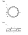
- Fig. 1 shows a frontal view of a rotor blade 1 according to an exemplary embodiment not forming part of the invention.
- the blade root 2 of the rotor blade 1 comprises connecting members 3 in the shape of two circumferentially aligned half-cylinders each extending about an angle of 180°.
- the connecting members 3 are disposed in a circumferentially adjacently alignment.
- the connecting members 3 comprise respective connecting elements 4 each comprising an axially extending connecting portion 5 in the shape of a threaded hole.
- the connecting portions 5 are adapted to be connected with corresponding connecting portions, i.e. threaded bolts or the like, of a rotor hub of a wind turbine, particularly a direct drive wind turbine (not shown).
- the respective connecting elements 4 are connected to respective circumferentially extending connecting members 3 being adjacently disposed in circumferentially direction so as to build a ring-like shape.
- the connecting members 3 are disposed within the fibre-reinforced casting or resin material of the rotor blade 1 (cf. fig. 2 , 3 ).
- the respective connecting members 3 are made of a casting material such as a castable metal or a fibre-reinforced plastic material.
- the connecting members 3 may even be manufactured by injection moulding.
- the connecting members 3 may be built as precast-components giving rise to a reduction of the manufacturing time of a respective rotor blade 1.
- the connecting members 3 are particularly advantageous in case of large-scaled rotor blades 1 which are usually manufactured into moulds disposed on top of each other.
- the connecting members 3 provide the blade root with mechanical stability, particularly stiffness, so that usually occurring ovalisation or deformation effects of the blade root 2 of the rotor blade 1 are efficiently avoided or at least reduced originating from the self-weight of the rotor blade 1 (cf. force indicating arrow F in fig. 1 ).
- the connecting members 3 comprise circumferentially aligned connecting elements 4 axially extending off the respective connecting members 3.
- the connecting elements 4 may be integrated within or integrally built with respective blade-like or cylinder-segment-like portions 6. Additionally stiffening components such as circular plates or the like are no longer necessary.
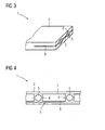
- Fig. 4 shows an enlarged detail view of the rotor blade 1 according to an exemplary embodiment of the invention.
- the respective connecting member 3 comprises two radially spaced connecting member elements 7, 8 each having the shape of respective cylinder-segments.
- the connecting elements 4 are disposed between the respective connecting member elements 7, 8, i.e. the connecting elements 4 interconnect the connecting member elements 7, 8.
- the connecting member 3 comprises a sandwich-construction with the respective connecting member elements 7, 8 serve as respective outer layers and the connecting elements 4 serve as an intermediate layer together with the casting material of the rotor blade 1 filling all respective apertures of the sandwich-construction.
- the sandwich-construction provides the blade root 2 with additional mechanical stability or stiffness respectively. Particularly, respective forces originated from the self-weight of the rotor blade 1 are counteracted.
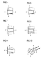
- FIG. 5 shows a connecting member 3 in the shape of a cylinder segment having circumferentially distributed connecting elements 4. Both axial edges and ending of the connecting member are straight cut. As is discernible, the connecting elements 4 extend in axial direction.
- the figures 6, 7 show respective connecting members 3 with their right axial edges or endings having a convex or concave curved shape.
- the connecting members 3 may be firmly attached within the casting material of the rotor blade 1 particularly in view of shear forces.
- Fig. 8 shows another alternative embodiment which differs from the proceeding embodiments in a blade root ring 9 being attached to the left face side of the respective connecting member 3.
- the blade root ring 9 is closed so that it provides a circumferential connection of the circumferentially adjacently disposed connecting members 3.
- the blade root 2 of the rotor blade 1 is provided with additional mechanical stability.
- the blade root ring 9 may be deemed in terms of a base plate of the blade root 2.
- connection of the cylinder segment-like portions 6 of the connecting members 3 alternating with respective connecting elements 4 of the embodiments shown in fig. 5 - 8 may be interpreted as respective duck feet.
- respective loads may be distributed over an enlarged area leading to a reduction of the stress and further to an efficient transfer of externally applied loads in the blade root 2 or rotor blade 1 respectively.
- Figures 9, 10 show a further alternative embodiment not forming part of the present invention.
- the connecting members 3 is not built as a cylinder segment but as a ring-segment with the connecting elements 4 axially extending of the connecting members 3. It is possible to manufacture a respective connecting member 3 either as an integral component or by firmly attaching respective connecting elements 4 to a respectively shaped connecting member 3.
- the surfaces of the connecting members 3 as well as the connecting elements 4 as well as respective blade root rings 9 may be provided with a three-dimensional structuring, particularly in the shape of axially extending recesses and/or radial holes.
- a three-dimensional structuring particularly in the shape of axially extending recesses and/or radial holes.
Description
- The invention refers to a rotor blade for a wind turbine, having an elongate blade base body with a number of connecting elements each comprising at least one axially extending connecting portion adapted to be connected with at least one corresponding connecting portion of a rotor hub of a wind turbine, whereby the respective connecting elements are connected to at least two circumferentially extending connecting members with the connecting members being adjacently disposed in circumferential direction so as to build a ring-like shape.
- Rotor blades for wind turbine are usually built as fibre-reinforced hollow composite structures. Hence, they are usually fabricated by impregnating respective aligned and orientated fibres or fibre clutches with a casting or resin material respectively. Respective connecting elements in the shape of studs or the like having respective connecting portions such as threaded holes are integrated within the casting material so as to provide an interface for a mechanical connection with respective corresponding connecting portions of a rotor hub such as threaded bolts or the like.
- Thereby, removing of the cast rotor blade from the mould is oftentimes problematic since particularly in the region of the ring-like shaped root of the blade ovalisation may occur due to the self-weight of the rotor blade. Respective ovally shaped or deformed rotor blades are difficult to machine and particularly difficult to mount on a respective rotor hub of a wind turbine.
- It has been proposed to strengthen the blade root by inserting respective metal rings in the region of the blade root while or before moulding. Another proposal to enhance the mechanical properties, in particular the stiffness of the blade root is to provide bulky circular plates with the blade root. This principle is of particular disadvantage regarding the manufacturing process of vacuum injection since the circular plates impairs the insertion of a respective mandrel for injecting the casting material. Another proposal was to provide the blade root with additional material, ie increase wall thicknesses, etc. in the blade root.
-
FR 2 863 321 - The respective approaches for strengthening respective blade roots are deemed as comparatively cumbersome and costly. It is the object of the invention to provide a rotor blade having a constructively simple design with enhanced mechanical properties in the region of the blade root.
- This is achieved by a rotor blade as has been initially described, wherein a respective connecting member comprises two radially spaced connecting member elements, whereby the connecting elements are disposed between the respective connecting member elements.
- The present invention is based on the idea to provide the blade root of a rotor blade with enhanced mechanical properties, ie particularly enhanced stiffness, by means of at least two respective connecting members being connected with the respective connecting elements, ie studs or the like. The connecting members are inserted in between respective fibres and/or the casting material of the rotor blade while moulding.
- The respective connecting members are of particular advantage when using segmented moulds or mould halves, eg for separately moulding two halves of a rotor blade which is oftentimes necessary for manufacturing large-scaled rotor blades. It is possible that the connecting members have to be machined before moulding.
- The respective connecting members act as connecting means for aligning the respective connecting elements in a given geometrical relationship. Each of the connecting members is preferably provided with a respective number of connecting elements. In favour, the total number of connecting elements is uniformly distributed over the respective connecting members, ie in the exemplary case of two connecting members each connecting member is connected with half of the total number of connecting elements.
- Generally, the respective connecting members are disposed in the region of the blade root. Yet, the concrete position of a respective connecting member may differ, whereby different strengthening effects may be accomplished in dependence of the radial position of the connecting members with respect to the centre axis of the rotor blade. Generally, the respective connecting members provide the blade root with additional mechanical stability, ie in particular stiffness so that ovalisation or deformation effects are avoided or at least reduced. Particularly, the respective connecting member is adapted to transfer and/or distribute respective externally applied loads into the blade root structure of the rotor blade.
- In either case, the respective connecting members are circumferentially adjacently disposed so as to build a ring-like shape. Thereby, a slight circumferential gap may be provided between the respective connecting members or the connecting members may be placed as a joint, ie in direct circumferential abutment.
- A connecting member may have the shape of a cylinder-segment, particularly a half-cylinder-segment, or a ring-segment, particularly a half-ring-segment. In such a manner, the connecting members have a ring-segment-like cross-section capable of encountering respective externally applied forces and capable of inhibiting any deformation or ovalisation effects of the blade root. Connecting members with respective shapes provide a huge surface so that respective loads may be distributed over an enlarged area leading to a reduction of stress. Aside, the transport of shear forces from the connecting member in the blade root is improved due to the large surface area of the respective connecting members. Hence, the connecting member is adapted to transfer externally applied loads, particularly shear loads, in the blade root of the rotor blade.
- It is possible that the connecting elements are integrally built with a respective connecting member or mounted to a respective connecting member. In either case a mechanically stable connection of a respective connecting member and respective connecting elements is given. In dependence of the material of the connecting member and the connecting elements, an integral, particularly casting, construction of both the connecting member and the connecting elements may be realised leading to additional mechanical stability. Alternatively, the respective connecting means may be mounted, ie firmly attached to a respective connecting member. In this case, respective corresponding connecting portions are provided for achieving a mechanically stable connection of the connecting members and the connecting elements. The connection may be detachable or non-detachable. Welding or bolted connections are applicable for providing a connection of a connecting member and respective connecting elements for instance.
- According to the invention, a respective connecting member comprises two radially spaced connecting member elements, whereby the connecting elements are disposed between the respective connecting member elements. Hence, a sandwich-construction is given, whereby the connecting member elements, which usually are shaped as ring- or cylinder segments, serve as outer layers and the connecting elements interconnecting the connecting member elements in radial direction serve as a respective intermediate layer disposed in between in the outer layers.
- This embodiment further leads to advantages regarding the integration of the connecting member within the casting material of the rotor blade since a number of apertures or the like are provided with the connecting member segments and the connecting elements which may be filled with the respective casting material of the rotor blade. Respective sandwich-structures provide the blade root with additional stiffness so that ovalisation and deformation effects may be avoided.
- A blade root ring may be attached to at least one face side of the respective connecting members in order to provide the respective connecting members with additional stiffness. The blade root ring serves to connect the respective circumferentially abutting connecting members so that they essentially behave like a closed ring in regard of their mechanical behaviour. Of course, both face sides of the connecting elements may be provided with respective blade root rings so as to further improve the stiffness of the connecting members and the blade root as a whole.
- It is possible that at least one face side of a connecting member is provided with a straight shape and/or curved shaped portions. This embodiment mainly refers to respective connecting means in the shape of cylinder-segments, whereby the design of the face side, ie the lateral area of a respective connecting member may be provided with respectively shaped designs in the region of its side edge or boarder. Thereby, it is aimed to give the connecting members a geometrical structure allowing a firm form closure with the respective casting material of the rotor blade encasing the connecting members. Hence, respective curved or undercut shaped portions or the like provide a mechanically firm placement or anchoring of the connecting members within the blade root particularly in view of applied shear forces.
- Essentially the same effect may be achieved by providing the surface of a connecting member with a three-dimensional structuring, particularly in the shape of axially extending recesses and/or radial holes. Hence, the connection, ie adhesion of the connecting members to the casting material of the rotor blade may be enhanced by anchoring the connecting members within the casting material of the rotor blade. It is understood that numerous differently shaped recesses, protrusions, apertures, etc. of a respective connecting member are applicable in this context. The same applies for the respective connecting elements as well as the blade root ring, if need be, i.e. their outer surface may also be provided with a three-dimensional structuring.
- The connecting member is preferably made of metal or plastic material, particularly fibre-reinforced plastic material. Generally, it is of advantage to build the connecting member of a casting material such as certain castable metals or plastics allowing a simple manufacturing of respective connecting members, if need be with integrated connecting elements. All kinds of metal and plastic casting materials are applicable, whereby in the latter case fibre-reinforced thermosetting or thermoplastic plastics may be used. Hence, it is even thinkable to manufacture a respective connecting member by injection moulding as long as high performance fibres such as particularly carbon fibres are integrated within the plastic material. The same applies for the respective connecting elements as well as the blade root ring, if need be, i.e. these parts are also preferably made of metal or a plastic material, particularly fibre-reinforced plastic material.
- Aside, the present invention relates to a wind turbine, particularly a direct drive wind turbine, comprising a rotor hub having at least one rotor blade attached thereto. The rotor blade is of the type as has been described before.
- In the following, the invention is described in detail as reference is made to the figures, whereby:
- fig. 1
- shows a frontal view of a rotor blade according to an exemplary embodiment not forming part of the invention;
- fig. 2
- shows an enlarged detail view of the rotor blade of
fig. 1 ; - fig. 3
- shows a perspective partial view of a rotor blade according to an exemplary embodiment not forming part of the invention;
- fig. 4
- shows an enlarged detail view of a rotor blade according to an exemplary embodiment of the invention;
- fig. 5-8
- show top partial views of rotor blades according to exemplary embodiments of the invention;
- fig. 9
- shows a partial top view of a connecting member according to an exemplary embodiment not forming part of the invention; and
- fig. 10
- shows a perspective view of
fig. 9 . -
Fig. 1 shows a frontal view of a rotor blade 1 according to an exemplary embodiment not forming part of the invention. Theblade root 2 of the rotor blade 1 comprises connectingmembers 3 in the shape of two circumferentially aligned half-cylinders each extending about an angle of 180°. As is discernible, the connectingmembers 3 are disposed in a circumferentially adjacently alignment. The connectingmembers 3 comprise respective connectingelements 4 each comprising an axially extending connectingportion 5 in the shape of a threaded hole. The connectingportions 5 are adapted to be connected with corresponding connecting portions, i.e. threaded bolts or the like, of a rotor hub of a wind turbine, particularly a direct drive wind turbine (not shown). Hence, the respective connectingelements 4 are connected to respective circumferentially extending connectingmembers 3 being adjacently disposed in circumferentially direction so as to build a ring-like shape. - Thereby, the connecting
members 3 are disposed within the fibre-reinforced casting or resin material of the rotor blade 1 (cf.fig. 2 ,3 ). The respective connectingmembers 3 are made of a casting material such as a castable metal or a fibre-reinforced plastic material. When using high performance fibres such as carbon fibres the connectingmembers 3 may even be manufactured by injection moulding. Thus, the connectingmembers 3 may be built as precast-components giving rise to a reduction of the manufacturing time of a respective rotor blade 1. - The connecting
members 3 are particularly advantageous in case of large-scaled rotor blades 1 which are usually manufactured into moulds disposed on top of each other. - The connecting
members 3 provide the blade root with mechanical stability, particularly stiffness, so that usually occurring ovalisation or deformation effects of theblade root 2 of the rotor blade 1 are efficiently avoided or at least reduced originating from the self-weight of the rotor blade 1 (cf. force indicating arrow F infig. 1 ). - As is particularly discernible from
fig. 2 , the connectingmembers 3 comprise circumferentially aligned connectingelements 4 axially extending off the respective connectingmembers 3. The connectingelements 4 may be integrated within or integrally built with respective blade-like or cylinder-segment-like portions 6. Additionally stiffening components such as circular plates or the like are no longer necessary. -
Fig. 4 shows an enlarged detail view of the rotor blade 1 according to an exemplary embodiment of the invention. In this embodiment, the respective connectingmember 3 comprises two radially spaced connectingmember elements 7, 8 each having the shape of respective cylinder-segments. The connectingelements 4 are disposed between the respective connectingmember elements 7, 8, i.e. the connectingelements 4 interconnect the connectingmember elements 7, 8. - In such a manner, the connecting
member 3 comprises a sandwich-construction with the respective connectingmember elements 7, 8 serve as respective outer layers and the connectingelements 4 serve as an intermediate layer together with the casting material of the rotor blade 1 filling all respective apertures of the sandwich-construction. The sandwich-construction provides theblade root 2 with additional mechanical stability or stiffness respectively. Particularly, respective forces originated from the self-weight of the rotor blade 1 are counteracted. - The
figures 5 - 8 show top partial views of rotor blades 1 according to exemplary embodiments of the invention.Fig. 5 shows a connectingmember 3 in the shape of a cylinder segment having circumferentially distributed connectingelements 4. Both axial edges and ending of the connecting member are straight cut. As is discernible, the connectingelements 4 extend in axial direction. - The
figures 6, 7 show respective connectingmembers 3 with their right axial edges or endings having a convex or concave curved shape. In such a manner, the connectingmembers 3 may be firmly attached within the casting material of the rotor blade 1 particularly in view of shear forces. -
Fig. 8 shows another alternative embodiment which differs from the proceeding embodiments in ablade root ring 9 being attached to the left face side of the respective connectingmember 3. Theblade root ring 9 is closed so that it provides a circumferential connection of the circumferentially adjacently disposed connectingmembers 3. Hence, theblade root 2 of the rotor blade 1 is provided with additional mechanical stability. Theblade root ring 9 may be deemed in terms of a base plate of theblade root 2. - The connection of the cylinder segment-
like portions 6 of the connectingmembers 3 alternating with respective connectingelements 4 of the embodiments shown infig. 5 - 8 may be interpreted as respective duck feet. In such a manner, respective loads may be distributed over an enlarged area leading to a reduction of the stress and further to an efficient transfer of externally applied loads in theblade root 2 or rotor blade 1 respectively. -
Figures 9, 10 show a further alternative embodiment not forming part of the present invention. In this case, the connectingmembers 3 is not built as a cylinder segment but as a ring-segment with the connectingelements 4 axially extending of the connectingmembers 3. It is possible to manufacture a respective connectingmember 3 either as an integral component or by firmly attaching respective connectingelements 4 to a respectively shaped connectingmember 3. - In either case, the surfaces of the connecting
members 3 as well as the connectingelements 4 as well as respective blade root rings 9 (as far as given) may be provided with a three-dimensional structuring, particularly in the shape of axially extending recesses and/or radial holes. In such a manner, the adherence of the casting material of the rotor blade 1, i.e. the connection between the connectingmembers 3 and the casting material of the rotor blade 1 may be further improved.
Claims (9)
- Rotor blade (1) for a wind turbine, having an elongate blade base body with a number of connecting elements (4) each comprising at least one axially extending connecting portion (5) adapted to be connected with at least one corresponding connecting portion of a rotor hub of a wind turbine, whereby the respective connecting elements (4) are connected to at least two circumferentially extending connecting members (3) with the connecting members (3) being adjacently disposed in circumferential direction so as to build a ring-like shape, characterised in that a respective connecting member (3) comprises two radially spaced connecting member elements (7, 8), whereby the connecting elements (4) are disposed between the respective connecting member elements (7, 8).
- Rotor blade according to claim 1, wherein the connecting member (3) has the shape of a cylinder-segment, particularly a half-cylinder-segment, or a ring-segment, particularly a half-ring-segment.
- Rotor blade according to claim 2, wherein the connecting member (3) is adapted to transfer externally applied loads, particularly shear loads, in the blade root (2) of the rotor blade (1).
- Rotor blade according to one of the preceding claims, wherein the connecting elements (4) are integrally built with a respective connecting member (3) or mounted to a respective connecting member (3).
- Rotor blade according to one of the preceding claims, wherein a blade root ring (9) is attached to at least one face side of the respective connecting members (3).
- Rotor blade according to one of the preceding claims, wherein at least one face side of a connecting member (3) is provided with a straight shape and/or curved shaped portions.
- Rotor blade according to one of the preceding claims, wherein the surface of a connecting member (3) is at least partially provided with a three-dimensional structuring, particularly in the shape of axially extending recesses and/or radial holes.
- Rotor blade according to one of the preceding claims, wherein the connecting member (3) is made of metal, particularly steel, or a plastic material, particularly a fibre-reinforced plastic material.
- Wind turbine comprising a rotor hub having at least one rotor blade (1) according to one of the preceding claims attached thereto.
Priority Applications (4)
| Application Number | Priority Date | Filing Date | Title |
|---|---|---|---|
| EP11169521.9A EP2532881B1 (en) | 2011-06-10 | 2011-06-10 | Rotor blade for a wind turbine |
| DK11169521.9T DK2532881T3 (en) | 2011-06-10 | 2011-06-10 | A rotor blade for a wind turbine |
| US13/490,581 US9234497B2 (en) | 2011-06-10 | 2012-06-07 | Rotor blade for a wind turbine |
| CN201210187957.2A CN102817791B (en) | 2011-06-10 | 2012-06-08 | Rotor blade for wind turbine |
Applications Claiming Priority (1)
| Application Number | Priority Date | Filing Date | Title |
|---|---|---|---|
| EP11169521.9A EP2532881B1 (en) | 2011-06-10 | 2011-06-10 | Rotor blade for a wind turbine |
Publications (3)
| Publication Number | Publication Date |
|---|---|
| EP2532881A2 EP2532881A2 (en) | 2012-12-12 |
| EP2532881A3 EP2532881A3 (en) | 2013-02-13 |
| EP2532881B1 true EP2532881B1 (en) | 2014-12-17 |
Family
ID=44583943
Family Applications (1)
| Application Number | Title | Priority Date | Filing Date |
|---|---|---|---|
| EP11169521.9A Active EP2532881B1 (en) | 2011-06-10 | 2011-06-10 | Rotor blade for a wind turbine |
Country Status (4)
| Country | Link |
|---|---|
| US (1) | US9234497B2 (en) |
| EP (1) | EP2532881B1 (en) |
| CN (1) | CN102817791B (en) |
| DK (1) | DK2532881T3 (en) |
Families Citing this family (8)
| Publication number | Priority date | Publication date | Assignee | Title |
|---|---|---|---|---|
| US20140119926A1 (en) * | 2012-10-31 | 2014-05-01 | General Electric Company | Wind turbine rotor blade assembly with a ring insert in the blade root |
| ITMI20130449A1 (en) | 2013-03-25 | 2014-09-26 | Wilic Sarl | SHOVEL ROUND OF AN AIR-CONVEYOR AND PROCEDURE FOR THE MANUFACTURE OF AN AIR SPREADER'S STONE ROOT |
| US9970304B2 (en) | 2015-07-22 | 2018-05-15 | General Electric Company | Rotor blade root assembly for a wind turbine |
| US10060411B2 (en) * | 2015-07-22 | 2018-08-28 | General Electric Company | Rotor blade root assembly for a wind turbine |
| US10626847B2 (en) | 2017-01-05 | 2020-04-21 | General Electric Company | Method for manufacturing a wind turbine rotor blade root section with pultruded rods and associated wind turbine blade |
| US10677216B2 (en) | 2017-10-24 | 2020-06-09 | General Electric Company | Wind turbine rotor blade components formed using pultruded rods |
| US11738530B2 (en) | 2018-03-22 | 2023-08-29 | General Electric Company | Methods for manufacturing wind turbine rotor blade components |
| EP3590690B1 (en) * | 2018-07-04 | 2020-12-23 | ABB Power Grids Switzerland AG | Fibre reinforced polymer tube |
Family Cites Families (11)
| Publication number | Priority date | Publication date | Assignee | Title |
|---|---|---|---|---|
| US4260332A (en) | 1979-03-22 | 1981-04-07 | Structural Composite Industries, Inc. | Composite spar structure having integral fitting for rotational hub mounting |
| DE3103710C2 (en) * | 1981-02-04 | 1983-03-24 | Messerschmitt-Bölkow-Blohm GmbH, 8000 München | "Rotor in shell design" |
| US4915590A (en) * | 1987-08-24 | 1990-04-10 | Fayette Manufacturing Corporation | Wind turbine blade attachment methods |
| DE10011464C1 (en) * | 2000-03-10 | 2001-08-16 | Aloys Wobben | Storage of an adjustable rotor blade of a wind turbine |
| EP1467853B1 (en) * | 2002-01-11 | 2007-03-28 | Fiberline A/S | A method of producing a fibre reinforced structural element |
| EP1486415A1 (en) * | 2003-06-12 | 2004-12-15 | SSP Technology A/S | Wind turbine blade and method of manufacturing a blade root |
| FR2863321A1 (en) | 2003-12-09 | 2005-06-10 | Ocea Sa | Wind generator`s blade for producing electricity, has at one of its ends cylindrical root to be fixed with hub of wind generator by screwing units cooperating with threaded bores carried by root |
| DE102007008167C5 (en) * | 2007-02-14 | 2016-07-07 | Nordex Energy Gmbh | Wind turbine with a rotor hub |
| DE102008021498A1 (en) | 2008-04-29 | 2009-11-05 | Repower Systems Ag | Method for manufacturing a blade connection of a rotor blade, a blade connection and a fastening element for a blade connection |
| ES2735227T3 (en) * | 2008-06-27 | 2019-12-17 | Siemens Gamesa Renewable Energy Innovation & Technology SL | Shovel insert |
| US9068559B2 (en) * | 2009-02-16 | 2015-06-30 | Vestas Wind Systems A/S | Rotor blade for a wind turbine and a method for making the same |
-
2011
- 2011-06-10 DK DK11169521.9T patent/DK2532881T3/en active
- 2011-06-10 EP EP11169521.9A patent/EP2532881B1/en active Active
-
2012
- 2012-06-07 US US13/490,581 patent/US9234497B2/en active Active
- 2012-06-08 CN CN201210187957.2A patent/CN102817791B/en active Active
Also Published As
| Publication number | Publication date |
|---|---|
| US9234497B2 (en) | 2016-01-12 |
| DK2532881T3 (en) | 2015-01-12 |
| CN102817791A (en) | 2012-12-12 |
| EP2532881A2 (en) | 2012-12-12 |
| CN102817791B (en) | 2016-12-14 |
| EP2532881A3 (en) | 2013-02-13 |
| US20120315145A1 (en) | 2012-12-13 |
Similar Documents
| Publication | Publication Date | Title |
|---|---|---|
| EP2532881B1 (en) | Rotor blade for a wind turbine | |
| EP2532880B1 (en) | Rotor blade for a wind turbine | |
| EP3121441B1 (en) | Rotor blade root assembly for a wind turbine | |
| EP3112668A1 (en) | Blade root section for a modular rotor blade and method of manufacturing same | |
| EP2516845B1 (en) | A hub for a wind turbine and a method for fabricating the hub | |
| EP2551512B1 (en) | Wind turbine blade connector assembly | |
| EP2917568B1 (en) | Wind turbine blade with fastening means | |
| CN102536632A (en) | Wind turbine blade and method for manufacturing a wind turbine blade with vortex generators | |
| US10273933B2 (en) | Wind turbine blade root and process for manufacturing a wind turbine blade root | |
| BR102016016090A2 (en) | root assemblies for a rotor blade of a wind turbine | |
| WO2012140039A2 (en) | Wind turbine blade comprising circumferential retaining means in root regions | |
| US9945353B2 (en) | Spoiler for a wind turbine blade | |
| EP2674612B1 (en) | Blade for a wind turbine | |
| EP2697047B1 (en) | Wind turbine blade comprising cylindrical metal inserts in a root region thereof | |
| CA2852334A1 (en) | Wind turbine blade and method of fabricating a wind turbine blade | |
| CN102626970A (en) | Method of moulding a wind-turbine blade | |
| JP7320602B2 (en) | Wind turbine blade root attachment system and manufacturing method | |
| CN101704302B (en) | Integrally forming mould of composite propeller and manufacture method thereof | |
| EP3345751A1 (en) | A method for manufacturing a wind turbine rotor blade root section with pultruded rods and associated wind turbine blade | |
| EP2697048B1 (en) | Wind turbine blade with elongated fastening members in the root region thereof | |
| CN110892150A (en) | Method of manufacturing a wind turbine blade and wind turbine blade thereof | |
| EP2617990B1 (en) | Anti-ovalization tool for introduction into a wind turbine blade root and method of reducing ovalization of a wind turbine blade root | |
| EP2623769A1 (en) | Wind turbine blade with a connection ring forming part of a blade root - to - hub connection | |
| CN108883588B (en) | Embedded element for a wind turbine blade | |
| EP3548261B1 (en) | Method and system for manufacturing a shear web for a wind turbine blade |
Legal Events
| Date | Code | Title | Description |
|---|---|---|---|
| PUAI | Public reference made under article 153(3) epc to a published international application that has entered the european phase |
Free format text: ORIGINAL CODE: 0009012 |
|
| AK | Designated contracting states |
Kind code of ref document: A2 Designated state(s): AL AT BE BG CH CY CZ DE DK EE ES FI FR GB GR HR HU IE IS IT LI LT LU LV MC MK MT NL NO PL PT RO RS SE SI SK SM TR |
|
| AX | Request for extension of the european patent |
Extension state: BA ME |
|
| PUAL | Search report despatched |
Free format text: ORIGINAL CODE: 0009013 |
|
| AK | Designated contracting states |
Kind code of ref document: A3 Designated state(s): AL AT BE BG CH CY CZ DE DK EE ES FI FR GB GR HR HU IE IS IT LI LT LU LV MC MK MT NL NO PL PT RO RS SE SI SK SM TR |
|
| AX | Request for extension of the european patent |
Extension state: BA ME |
|
| RIC1 | Information provided on ipc code assigned before grant |
Ipc: F03D 1/06 20060101ALI20130110BHEP Ipc: F03D 1/00 20060101AFI20130110BHEP |
|
| RAP1 | Party data changed (applicant data changed or rights of an application transferred) |
Owner name: SIEMENS AKTIENGESELLSCHAFT |
|
| 17P | Request for examination filed |
Effective date: 20130206 |
|
| TPAC | Observations filed by third parties |
Free format text: ORIGINAL CODE: EPIDOSNTIPA |
|
| 17Q | First examination report despatched |
Effective date: 20130624 |
|
| GRAP | Despatch of communication of intention to grant a patent |
Free format text: ORIGINAL CODE: EPIDOSNIGR1 |
|
| INTG | Intention to grant announced |
Effective date: 20140715 |
|
| GRAS | Grant fee paid |
Free format text: ORIGINAL CODE: EPIDOSNIGR3 |
|
| GRAA | (expected) grant |
Free format text: ORIGINAL CODE: 0009210 |
|
| AK | Designated contracting states |
Kind code of ref document: B1 Designated state(s): AL AT BE BG CH CY CZ DE DK EE ES FI FR GB GR HR HU IE IS IT LI LT LU LV MC MK MT NL NO PL PT RO RS SE SI SK SM TR |
|
| REG | Reference to a national code |
Ref country code: GB Ref legal event code: FG4D |
|
| REG | Reference to a national code |
Ref country code: CH Ref legal event code: EP |
|
| REG | Reference to a national code |
Ref country code: DK Ref legal event code: T3 Effective date: 20150108 |
|
| REG | Reference to a national code |
Ref country code: IE Ref legal event code: FG4D |
|
| REG | Reference to a national code |
Ref country code: AT Ref legal event code: REF Ref document number: 702140 Country of ref document: AT Kind code of ref document: T Effective date: 20150115 |
|
| REG | Reference to a national code |
Ref country code: DE Ref legal event code: R096 Ref document number: 602011012234 Country of ref document: DE Effective date: 20150129 |
|
| PG25 | Lapsed in a contracting state [announced via postgrant information from national office to epo] |
Ref country code: FI Free format text: LAPSE BECAUSE OF FAILURE TO SUBMIT A TRANSLATION OF THE DESCRIPTION OR TO PAY THE FEE WITHIN THE PRESCRIBED TIME-LIMIT Effective date: 20141217 Ref country code: NO Free format text: LAPSE BECAUSE OF FAILURE TO SUBMIT A TRANSLATION OF THE DESCRIPTION OR TO PAY THE FEE WITHIN THE PRESCRIBED TIME-LIMIT Effective date: 20150317 Ref country code: LT Free format text: LAPSE BECAUSE OF FAILURE TO SUBMIT A TRANSLATION OF THE DESCRIPTION OR TO PAY THE FEE WITHIN THE PRESCRIBED TIME-LIMIT Effective date: 20141217 |
|
| REG | Reference to a national code |
Ref country code: LT Ref legal event code: MG4D |
|
| PG25 | Lapsed in a contracting state [announced via postgrant information from national office to epo] |
Ref country code: HR Free format text: LAPSE BECAUSE OF FAILURE TO SUBMIT A TRANSLATION OF THE DESCRIPTION OR TO PAY THE FEE WITHIN THE PRESCRIBED TIME-LIMIT Effective date: 20141217 Ref country code: SE Free format text: LAPSE BECAUSE OF FAILURE TO SUBMIT A TRANSLATION OF THE DESCRIPTION OR TO PAY THE FEE WITHIN THE PRESCRIBED TIME-LIMIT Effective date: 20141217 Ref country code: RS Free format text: LAPSE BECAUSE OF FAILURE TO SUBMIT A TRANSLATION OF THE DESCRIPTION OR TO PAY THE FEE WITHIN THE PRESCRIBED TIME-LIMIT Effective date: 20141217 Ref country code: LV Free format text: LAPSE BECAUSE OF FAILURE TO SUBMIT A TRANSLATION OF THE DESCRIPTION OR TO PAY THE FEE WITHIN THE PRESCRIBED TIME-LIMIT Effective date: 20141217 Ref country code: GR Free format text: LAPSE BECAUSE OF FAILURE TO SUBMIT A TRANSLATION OF THE DESCRIPTION OR TO PAY THE FEE WITHIN THE PRESCRIBED TIME-LIMIT Effective date: 20150318 |
|
| REG | Reference to a national code |
Ref country code: AT Ref legal event code: MK05 Ref document number: 702140 Country of ref document: AT Kind code of ref document: T Effective date: 20141217 |
|
| PG25 | Lapsed in a contracting state [announced via postgrant information from national office to epo] |
Ref country code: NL Free format text: LAPSE BECAUSE OF FAILURE TO SUBMIT A TRANSLATION OF THE DESCRIPTION OR TO PAY THE FEE WITHIN THE PRESCRIBED TIME-LIMIT Effective date: 20141217 |
|
| PG25 | Lapsed in a contracting state [announced via postgrant information from national office to epo] |
Ref country code: ES Free format text: LAPSE BECAUSE OF FAILURE TO SUBMIT A TRANSLATION OF THE DESCRIPTION OR TO PAY THE FEE WITHIN THE PRESCRIBED TIME-LIMIT Effective date: 20141217 Ref country code: CZ Free format text: LAPSE BECAUSE OF FAILURE TO SUBMIT A TRANSLATION OF THE DESCRIPTION OR TO PAY THE FEE WITHIN THE PRESCRIBED TIME-LIMIT Effective date: 20141217 Ref country code: RO Free format text: LAPSE BECAUSE OF FAILURE TO SUBMIT A TRANSLATION OF THE DESCRIPTION OR TO PAY THE FEE WITHIN THE PRESCRIBED TIME-LIMIT Effective date: 20141217 Ref country code: EE Free format text: LAPSE BECAUSE OF FAILURE TO SUBMIT A TRANSLATION OF THE DESCRIPTION OR TO PAY THE FEE WITHIN THE PRESCRIBED TIME-LIMIT Effective date: 20141217 Ref country code: SK Free format text: LAPSE BECAUSE OF FAILURE TO SUBMIT A TRANSLATION OF THE DESCRIPTION OR TO PAY THE FEE WITHIN THE PRESCRIBED TIME-LIMIT Effective date: 20141217 |
|
| PG25 | Lapsed in a contracting state [announced via postgrant information from national office to epo] |
Ref country code: IS Free format text: LAPSE BECAUSE OF FAILURE TO SUBMIT A TRANSLATION OF THE DESCRIPTION OR TO PAY THE FEE WITHIN THE PRESCRIBED TIME-LIMIT Effective date: 20150417 Ref country code: PL Free format text: LAPSE BECAUSE OF FAILURE TO SUBMIT A TRANSLATION OF THE DESCRIPTION OR TO PAY THE FEE WITHIN THE PRESCRIBED TIME-LIMIT Effective date: 20141217 Ref country code: AT Free format text: LAPSE BECAUSE OF FAILURE TO SUBMIT A TRANSLATION OF THE DESCRIPTION OR TO PAY THE FEE WITHIN THE PRESCRIBED TIME-LIMIT Effective date: 20141217 |
|
| REG | Reference to a national code |
Ref country code: DE Ref legal event code: R097 Ref document number: 602011012234 Country of ref document: DE |
|
| PLBE | No opposition filed within time limit |
Free format text: ORIGINAL CODE: 0009261 |
|
| STAA | Information on the status of an ep patent application or granted ep patent |
Free format text: STATUS: NO OPPOSITION FILED WITHIN TIME LIMIT |
|
| 26N | No opposition filed |
Effective date: 20150918 |
|
| PG25 | Lapsed in a contracting state [announced via postgrant information from national office to epo] |
Ref country code: IT Free format text: LAPSE BECAUSE OF FAILURE TO SUBMIT A TRANSLATION OF THE DESCRIPTION OR TO PAY THE FEE WITHIN THE PRESCRIBED TIME-LIMIT Effective date: 20141217 |
|
| PG25 | Lapsed in a contracting state [announced via postgrant information from national office to epo] |
Ref country code: MC Free format text: LAPSE BECAUSE OF FAILURE TO SUBMIT A TRANSLATION OF THE DESCRIPTION OR TO PAY THE FEE WITHIN THE PRESCRIBED TIME-LIMIT Effective date: 20141217 |
|
| REG | Reference to a national code |
Ref country code: CH Ref legal event code: PL |
|
| PG25 | Lapsed in a contracting state [announced via postgrant information from national office to epo] |
Ref country code: SI Free format text: LAPSE BECAUSE OF FAILURE TO SUBMIT A TRANSLATION OF THE DESCRIPTION OR TO PAY THE FEE WITHIN THE PRESCRIBED TIME-LIMIT Effective date: 20141217 Ref country code: LU Free format text: LAPSE BECAUSE OF FAILURE TO SUBMIT A TRANSLATION OF THE DESCRIPTION OR TO PAY THE FEE WITHIN THE PRESCRIBED TIME-LIMIT Effective date: 20150610 |
|
| REG | Reference to a national code |
Ref country code: IE Ref legal event code: MM4A |
|
| REG | Reference to a national code |
Ref country code: FR Ref legal event code: ST Effective date: 20160229 |
|
| PG25 | Lapsed in a contracting state [announced via postgrant information from national office to epo] |
Ref country code: IE Free format text: LAPSE BECAUSE OF NON-PAYMENT OF DUE FEES Effective date: 20150610 Ref country code: CH Free format text: LAPSE BECAUSE OF NON-PAYMENT OF DUE FEES Effective date: 20150630 Ref country code: LI Free format text: LAPSE BECAUSE OF NON-PAYMENT OF DUE FEES Effective date: 20150630 |
|
| PG25 | Lapsed in a contracting state [announced via postgrant information from national office to epo] |
Ref country code: FR Free format text: LAPSE BECAUSE OF NON-PAYMENT OF DUE FEES Effective date: 20150630 Ref country code: BE Free format text: LAPSE BECAUSE OF FAILURE TO SUBMIT A TRANSLATION OF THE DESCRIPTION OR TO PAY THE FEE WITHIN THE PRESCRIBED TIME-LIMIT Effective date: 20141217 |
|
| PG25 | Lapsed in a contracting state [announced via postgrant information from national office to epo] |
Ref country code: MT Free format text: LAPSE BECAUSE OF FAILURE TO SUBMIT A TRANSLATION OF THE DESCRIPTION OR TO PAY THE FEE WITHIN THE PRESCRIBED TIME-LIMIT Effective date: 20141217 |
|
| PG25 | Lapsed in a contracting state [announced via postgrant information from national office to epo] |
Ref country code: SM Free format text: LAPSE BECAUSE OF FAILURE TO SUBMIT A TRANSLATION OF THE DESCRIPTION OR TO PAY THE FEE WITHIN THE PRESCRIBED TIME-LIMIT Effective date: 20141217 Ref country code: BG Free format text: LAPSE BECAUSE OF FAILURE TO SUBMIT A TRANSLATION OF THE DESCRIPTION OR TO PAY THE FEE WITHIN THE PRESCRIBED TIME-LIMIT Effective date: 20141217 Ref country code: HU Free format text: LAPSE BECAUSE OF FAILURE TO SUBMIT A TRANSLATION OF THE DESCRIPTION OR TO PAY THE FEE WITHIN THE PRESCRIBED TIME-LIMIT; INVALID AB INITIO Effective date: 20110610 |
|
| PG25 | Lapsed in a contracting state [announced via postgrant information from national office to epo] |
Ref country code: CY Free format text: LAPSE BECAUSE OF FAILURE TO SUBMIT A TRANSLATION OF THE DESCRIPTION OR TO PAY THE FEE WITHIN THE PRESCRIBED TIME-LIMIT Effective date: 20141217 |
|
| PG25 | Lapsed in a contracting state [announced via postgrant information from national office to epo] |
Ref country code: TR Free format text: LAPSE BECAUSE OF FAILURE TO SUBMIT A TRANSLATION OF THE DESCRIPTION OR TO PAY THE FEE WITHIN THE PRESCRIBED TIME-LIMIT Effective date: 20141217 |
|
| PG25 | Lapsed in a contracting state [announced via postgrant information from national office to epo] |
Ref country code: MK Free format text: LAPSE BECAUSE OF FAILURE TO SUBMIT A TRANSLATION OF THE DESCRIPTION OR TO PAY THE FEE WITHIN THE PRESCRIBED TIME-LIMIT Effective date: 20141217 |
|
| PG25 | Lapsed in a contracting state [announced via postgrant information from national office to epo] |
Ref country code: PT Free format text: LAPSE BECAUSE OF FAILURE TO SUBMIT A TRANSLATION OF THE DESCRIPTION OR TO PAY THE FEE WITHIN THE PRESCRIBED TIME-LIMIT Effective date: 20141217 |
|
| PG25 | Lapsed in a contracting state [announced via postgrant information from national office to epo] |
Ref country code: AL Free format text: LAPSE BECAUSE OF FAILURE TO SUBMIT A TRANSLATION OF THE DESCRIPTION OR TO PAY THE FEE WITHIN THE PRESCRIBED TIME-LIMIT Effective date: 20141217 |
|
| REG | Reference to a national code |
Ref country code: DE Ref legal event code: R081 Ref document number: 602011012234 Country of ref document: DE Owner name: SIEMENS GAMESA RENEWABLE ENERGY A/S, DK Free format text: FORMER OWNER: SIEMENS AKTIENGESELLSCHAFT, 80333 MUENCHEN, DE |
|
| REG | Reference to a national code |
Ref country code: GB Ref legal event code: 732E Free format text: REGISTERED BETWEEN 20191128 AND 20191204 |
|
| PGFP | Annual fee paid to national office [announced via postgrant information from national office to epo] |
Ref country code: DK Payment date: 20230621 Year of fee payment: 13 Ref country code: DE Payment date: 20230620 Year of fee payment: 13 |
|
| PGFP | Annual fee paid to national office [announced via postgrant information from national office to epo] |
Ref country code: GB Payment date: 20230622 Year of fee payment: 13 |