EP3476795A1 - Assist suit - Google Patents
Assist suit Download PDFInfo
- Publication number
- EP3476795A1 EP3476795A1 EP17820125.7A EP17820125A EP3476795A1 EP 3476795 A1 EP3476795 A1 EP 3476795A1 EP 17820125 A EP17820125 A EP 17820125A EP 3476795 A1 EP3476795 A1 EP 3476795A1
- Authority
- EP
- European Patent Office
- Prior art keywords
- assist
- worker
- winch
- leg
- limit value
- Prior art date
- Legal status (The legal status is an assumption and is not a legal conclusion. Google has not performed a legal analysis and makes no representation as to the accuracy of the status listed.)
- Granted
Links
Images





Classifications
-
- B—PERFORMING OPERATIONS; TRANSPORTING
- B25—HAND TOOLS; PORTABLE POWER-DRIVEN TOOLS; MANIPULATORS
- B25J—MANIPULATORS; CHAMBERS PROVIDED WITH MANIPULATION DEVICES
- B25J9/00—Program-controlled manipulators
- B25J9/0006—Exoskeletons, i.e. resembling a human figure
-
- A—HUMAN NECESSITIES
- A61—MEDICAL OR VETERINARY SCIENCE; HYGIENE
- A61H—PHYSICAL THERAPY APPARATUS, e.g. DEVICES FOR LOCATING OR STIMULATING REFLEX POINTS IN THE BODY; ARTIFICIAL RESPIRATION; MASSAGE; BATHING DEVICES FOR SPECIAL THERAPEUTIC OR HYGIENIC PURPOSES OR SPECIFIC PARTS OF THE BODY
- A61H3/00—Appliances for aiding patients or disabled persons to walk about
-
- B—PERFORMING OPERATIONS; TRANSPORTING
- B25—HAND TOOLS; PORTABLE POWER-DRIVEN TOOLS; MANIPULATORS
- B25J—MANIPULATORS; CHAMBERS PROVIDED WITH MANIPULATION DEVICES
- B25J13/00—Controls for manipulators
- B25J13/06—Control stands, e.g. consoles, switchboards
-
- B—PERFORMING OPERATIONS; TRANSPORTING
- B25—HAND TOOLS; PORTABLE POWER-DRIVEN TOOLS; MANIPULATORS
- B25J—MANIPULATORS; CHAMBERS PROVIDED WITH MANIPULATION DEVICES
- B25J9/00—Program-controlled manipulators
- B25J9/0009—Constructional details, e.g. manipulator supports, bases
-
- B—PERFORMING OPERATIONS; TRANSPORTING
- B25—HAND TOOLS; PORTABLE POWER-DRIVEN TOOLS; MANIPULATORS
- B25J—MANIPULATORS; CHAMBERS PROVIDED WITH MANIPULATION DEVICES
- B25J9/00—Program-controlled manipulators
- B25J9/10—Program-controlled manipulators characterised by positioning means for manipulator elements
- B25J9/1005—Program-controlled manipulators characterised by positioning means for manipulator elements comprising adjusting means
- B25J9/101—Program-controlled manipulators characterised by positioning means for manipulator elements comprising adjusting means using limit-switches, -stops
-
- B—PERFORMING OPERATIONS; TRANSPORTING
- B66—HOISTING; LIFTING; HAULING
- B66D—CAPSTANS; WINCHES; TACKLES, e.g. PULLEY BLOCKS; HOISTS
- B66D3/00—Portable or mobile lifting or hauling appliances
- B66D3/18—Power-operated hoists
-
- B—PERFORMING OPERATIONS; TRANSPORTING
- B66—HOISTING; LIFTING; HAULING
- B66F—HOISTING, LIFTING, HAULING OR PUSHING, NOT OTHERWISE PROVIDED FOR, e.g. DEVICES WHICH APPLY A LIFTING OR PUSHING FORCE DIRECTLY TO THE SURFACE OF A LOAD
- B66F19/00—Hoisting, lifting, hauling or pushing, not otherwise provided for
Definitions
- the present invention relates to an assist suit that is used fitted to a worker, and assists movement of the worker.
- an assist suit described in Patent Document 1 is already known.
- the assist suit described in Patent Document 1 includes a body portion fitted to the back of a worker, and a waist belt (an "attachment belt” in Patent Document 1) that extends from the body portion and is wound around the waist of the worker to fit the body portion to the worker.
- the assist suit described in Patent Document 1 has arm portions ("upper arm portions” in Patent Document 1) that extend to the front side from the body portion through an area above the worker, hand portions suspended from tip end portions of the arm portions through winch wires ("wires" in Patent Document 1) and serving as handles for the worker in a state where the hand portions have been attached to an object to be lifted, and a winch device (a "drive device” in Patent Document 1) capable of winding and unwinding the winch wires.
- the assist suit described in Patent Document 1 is provided with a leg assist device (a "leg action portion” in Patent Document 1) that extends to the front side from the body portion through areas beside the worker, and assists the worker in a standing movement by exerting a pushing action on a thigh of the worker from the front side.
- a leg assist device a "leg action portion” in Patent Document 1
- a standing movement and a movement to lift the package are assisted by the assist suit.
- an assist suit described in Patent Document 2 (a "power assist suit” in that document) is already known.
- the power assist suit described in Patent Document 2 includes lower leg parts that can be fitted to lower limbs, and upper limb parts that can be fitted to upper limbs.
- the waist belt when the worker winds the waist belt around their own waist, the waist belt may be wound at a position higher or lower than the height assumed by the designer. In that case, the positions of the hand portions and the leg assist device also are at a position higher or lower than the height assumed by the designer. As a result, the worker may feel uncomfortable about the positions of the hand portions and the leg assist device, or movement may be insufficiently assisted.
- a manually operated operation portion (an "operation switch” in that document) is positioned on the back of the worker in an upper limb part, so in a state where the worker is wearing the assist suit, it is difficult for the worker to reach the operation portion with their hand, and therefore it is not easy to manually operate the operation portion.
- the present invention includes:
- the height where the waist belt is wound easily matches the height assumed by the designer. That is, the positions of the hand portion and the leg assist device also easily match the height assumed by the designer.
- the positioning mechanism is a recessed portion that is recessed in a belt thickness direction formed from an intermediate portion to a lower end portion in a vertical direction of the back surface contact portion.
- the worker can obtain a feeling of good fit in a state with the recessed portion contacting the worker's buttocks and a portion on the upper side relative to the recessed portion contacting the worker's waist.
- the worker easily winds the waist belt at a height where the recessed portion contacts the buttocks and the portion on the upper side relative to the recessed portion contacts the waist. Therefore, the recessed portion functions as a positioning mechanism.
- a positioning mechanism can be provided by a simple configuration in which merely the recessed portion is provided.
- a stepped portion is formed between the recessed portion in the back surface contact portion and a portion on an upper side relative to the recessed portion.
- the weight of a package and the assist suit are mainly applied to the waist belt. Therefore, it is assumed that the height of the waist belt gradually drops during work.
- the stepped portion catches on the upper portion of the buttocks of the worker. Therefore, it is difficult for the height of the waist belt to drop during work.
- the leg assist device has an operation arm supported by the body portion in a state capable of swinging in the vertical direction, and a leg holding portion supported by the operation arm and fitted to a thigh of the worker, and is configured such that by causing the operation arm to swing in the vertical direction, the leg assist device acts on the thigh of the worker through the leg holding portion, and in a state where the body portion and the leg holding portion have been fitted to the worker, a pivot axis of the operation arm is positioned at the same height as the stepped portion or lower than the stepped portion.
- the vertical swinging center (hip joint) of the thigh of the worker is easily positioned at the same height as the stepped portion or lower than the stepped portion. Furthermore, according to the above configuration, the pivot axis of the operation arm is also positioned at the same height as the stepped portion or lower than the stepped portion.
- the height of the pivot axis of the operation arm easily becomes the same as the height of the vertical swinging center of the thigh of the worker. Also, in a case where the height of the pivot axis of the operation arm is the same as the vertical swinging center of the thigh of the worker, the leg assist device can act favorably on the thigh of the worker.
- the leg assist device easily acts favorably on the thigh of the worker.
- the pivot axis is positioned higher than a lower end portion of the waist belt.
- the vertical swinging center (hip joint) of the thigh of the worker is easily positioned higher than the lower end portion of the waist belt. Furthermore, according to the above configuration, the pivot axis of the operation arm is also positioned higher than the lower end portion of the waist belt.
- the height of the pivot axis of the operation arm easily becomes the same as the height of the vertical swinging center of the thigh of the worker. Also, in a case where the height of the pivot axis of the operation arm is the same as the vertical swinging center of the thigh of the worker, the leg assist device can act favorably on the thigh of the worker.
- the leg assist device easily acts favorably on the thigh of the worker.
- the positioning mechanism is formed spanning across left and right ends of the back surface contact portion.
- a wide and stable positioning mechanism is more easily formed than in a case where a positioning mechanism is formed only at the left or right end portion of the back surface contact portion.
- a left-right pair of shoulder belts hooked over both shoulders of the worker are provided; wherein upper side end portions of the left-right pair of shoulder belts are supported by an upper side portion of the body portion, lower side end portions of the left-right pair of shoulder belts are supported by a lower side portion of the body portion, and an interval between the upper side end portions in the left-right pair of shoulder belts is narrower than an interval between the lower side end portions in the left-right pair of shoulder belts.
- the shoulder belts can shift more to the left or right.
- inconveniences such as the body portion tilting greatly or the shoulder belts separating from the shoulders of the worker may occur.
- the interval between the worker's neck and the left-right pair of shoulder belts is comparatively small. Therefore, the width in which the shoulder belts can shift to the left or right is small. Accordingly, it is unlikely that inconveniences such as the body portion tilting greatly or the shoulder belts separating from the shoulders of the worker will occur.
- the upper side end portions of the left-right pair of shoulder belts are supported by a center portion in a left-right direction of the body portion, and the lower side end portions of the left-right pair of shoulder belts are supported by left and right end portions of the body portion.
- the upper side end portions of the left-right pair of shoulder belts are supported by the center portion in the left-right direction of the body portion, so in a state where the left-right pair of shoulder belts have been hooked over both shoulders of the worker, the interval between the worker's neck and the left-right pair of shoulder belts is particularly small. Accordingly, it is particularly unlikely that inconveniences such as the body portion tilting greatly or the shoulder belts separating from the shoulders of the worker will occur.
- the interval between the left-right pair of shoulder belts increases in the downward direction. Therefore, the worker can easily pass both arms through the left-right pair of shoulder belts. Also, the worker can easily hook the left-right pair of shoulder belts over both shoulders.
- the present invention includes:
- the operation portion is positioned beside the worker, so in a state where the worker is wearing the assist suit, it is easy for the worker to reach the operation portion with their hand, and therefore it is easy to manually operate the operation portion.
- a left-right pair of the leg assist devices are provided; wherein a first operation portion is disposed as the operation portion in a portion positioned beside the worker in a right side leg assist device among the left-right pair of leg assist devices, and a second operation portion is disposed as the operation portion in a portion positioned beside the worker in a left side leg assist device among the left-right pair of leg assist devices.
- the first operation portion is positioned to the right side of the worker and the second operation portion is positioned to the left side of the worker.
- the first operation portion is adopted as an operation portion having a comparatively high frequency of use and the second operation portion is adopted as an operation portion having a comparatively low frequency of use, it is possible to realize a layout suitable for a right-handed worker.
- the operation portion is a power operation portion that switches main power on or off.
- the power operation portion which has a comparatively high frequency of use, is positioned beside the worker, so in a state where the worker is wearing the assist suit, it is easy for the worker to reach the power operation portion with their hand, and therefore it is easy to manually operate the power operation portion.
- the leg assist upper/lower limit value setting portion sets the operation position of the leg assist device at the time when the leg assist change command operation portion was manually operated to the leg assist upper limit value or the leg assist lower limit value.
- the operation position of the leg assist device is set to the leg assist upper limit value or the leg assist lower limit value after the worker actually operates the leg assist device and confirms that operation position, so it is possible for the worker to easily change the leg assist upper limit value or the leg assist lower limit value according to their own body type or working manner.
- an area on an upper limit side in the operation range of the leg assist device is represented as a leg assist upper limit side area
- an area on a lower limit side in the operation range of the leg assist device is represented as a leg assist lower limit side area
- the leg assist upper/lower limit value setting portion if the operation position of the leg assist device belongs to the leg assist upper limit side area, sets the operation position of the leg assist device at the time when the leg assist change command operation portion was manually operated to the leg assist upper limit value, and if the operation position of the leg assist device belongs to the leg assist lower limit side area, sets the operation position of the leg assist device at the time when the leg assist change command operation portion was manually operated to the leg assist lower limit value.
- the leg assist upper/lower limit value setting portion automatically judges whether the operation position of the leg assist device at the time when the leg assist change command operation portion was manually operated should be set to the leg assist upper limit value or to the leg assist lower limit value, and then sets the operation position of the leg assist device at the time when the leg assist change command operation portion was manually operated to the leg assist upper limit value or the leg assist lower limit value.
- leg assist upper limit value or the leg assist lower limit value it is possible to easily change the leg assist upper limit value or the leg assist lower limit value, without the nuisance of the worker judging whether the operation position of the leg assist device at the time when the leg assist change command operation portion was manually operated should be set to the leg assist upper limit value or to the leg assist lower limit value.
- the winch assist upper/lower limit value setting portion sets the operation position of the winch device at the time when the winch assist change command operation portion was manually operated to the winch assist upper limit value or the winch assist lower limit value.
- the operation position of the winch device is set to the winch assist upper limit value or the winch assist lower limit value after the worker actually operates the winch device and confirms that operation position, so it is possible for the worker to easily change the winch assist upper limit value or the winch assist lower limit value according to their own body type or working manner.
- an area on an upper limit side in the operation range of the winch device is represented as a winch assist upper limit side area
- an area on a lower limit side in the operation range of the winch device is represented as a winch assist lower limit side area
- the winch assist upper/lower limit value setting portion if the operation position of the winch device belongs to the winch assist upper limit side area, sets the operation position of the winch device at the time when the winch assist change command operation portion was manually operated to the winch assist upper limit value, and if the operation position of the winch device belongs to the winch assist lower limit side area, sets the operation position of the winch device at the time when the winch assist change command operation portion was manually operated to the winch assist lower limit value.
- the winch assist upper/lower limit value setting portion automatically judges whether the operation position of the winch device at the time when the winch assist change command operation portion was manually operated should be set to the winch assist upper limit value or to the winch assist lower limit value, and then sets the operation position of the winch device at the time when the winch assist change command operation portion was manually operated to the winch assist upper limit value or the winch assist lower limit value.
- the front-rear direction, the left-right direction, and the up-down direction are described as follows. That is, in a state where the worker is wearing an assist suit 1, viewed from the perspective of the worker, the front side is "front”, the rear side is “rear”, the right side is “right”, the left side is “left”, the upper side is “upper”, and the lower side is “lower”.
- FIGS. 1 and 2 show the overall configuration of the assist suit 1 according to the present invention.
- the assist suit 1 includes a body portion 2. Also, a waist belt 3 is extended from the body portion 2. The waist belt 3 is supported at a lower side portion in the body portion 2. Note that in the lower side portion of the body portion 2, a portion supporting the waist belt 3 spans across left and right end portions of the body portion 2.
- the waist belt 3 is wound around the waist of the worker to fit the body portion 2 to the worker. Also, when the waist belt 3 is wound around the waist of the worker, the body portion 2 is in a state fitted to the back of the worker.
- the assist suit 1 includes the body portion 2 fitted to the back of the worker, and the waist belt 3 that extends from the body portion 2 and is wound around the waist of the worker to fit the body portion 2 to the worker.
- the waist belt 3 includes an insertion-type buckle 32.
- the worker When winding the waist belt 3 around the waist, the worker first detaches the insertion-type buckle 32. Then, the worker winds the waist belt 3 around the waist and couples the insertion-type buckle 32. In this way, the waist belt 3 is kept in a state wound around the waist of the worker.
- the assist suit 1 includes a left-right pair of arm portions 4. As shown in FIGS. 3 and 4 , the left-right pair of arm portions 4 extend to the front side from the body portion 2 through an area above the shoulders of the worker.
- the assist suit 1 includes the arm portions 4 that extend to the front side from the body portion 2 through an area above the worker.
- hand portions 6 are suspended from tip end portions of each of the left-right pair of arm portions 4 through winch wires 5.
- the hand portions 6 are configured so as to be capable of being attached to an object to be lifted.
- the hand portions 6 are configured so as to serve as handles for the worker in a state where the hand portions 6 have been attached to an object to be lifted.
- the assist suit 1 includes the hand portions 6 suspended from tip end portions of the arm portions 4 through the winch wires 5, and serving as handles for the worker in a state where the hand portions 6 have been attached to an object to be lifted.
- a raising switch 61 is provided in the hand portion 6 on the right side. Also, a lowering switch 62 is provided in the hand portion 6 on the left side.
- a winch device 10 is attached to an upper portion of a rear face of the body portion 2. Also, a battery 9 is attached below the winch device 10.
- the winch wires 5 extend from winch device 10. Also, the winch device 10 has a winch electric motor 11. The winch device 10 is capable of winding and unwinding the winch wires 5 using rotational driving of the winch electric motor 11.
- the assist suit 1 includes the winch device 10 capable of winding and unwinding the winch wires 5.
- the assist suit 1 has a left-right pair of shoulder belts 8 hooked over both shoulders of the worker.
- the left-right pair of shoulder belts 8 are pullout-type shoulder belts.
- the weight of the package and the assist suit 1 is mainly applied to the waist belt 3.
- the worker can stably support the weight of the package and the assist suit 1 using the waist.
- the left-right pair of shoulder belts 8 the body portion 2 is prevented from separating from the back of the worker by falling backward.
- the waist belt 3 has a back surface contact portion 31. As shown in FIG. 5 , the back surface contact portion 31 contacts the back surface of the worker in a state where the waist belt 3 has been wound around the waist of the worker.
- a bulging portion 31a and a recessed portion 31c are formed in the back surface contact portion 31.
- the bulging portion 31a bulges in the belt thickness direction compared to the recessed portion 31c.
- the recessed portion 31c is recessed in the belt thickness direction compared to the bulging portion 31a.
- the recessed portion 31c is formed as a surface in the vertical direction.
- the recessed portion 31c is formed from an intermediate portion to a lower end portion in the vertical direction of the back surface contact portion 31. Also, the bulging portion 31a is formed on the upper side relative to the recessed portion 31c. Further, a stepped portion 31b is formed between the recessed portion 31c and the bulging portion 31a.
- the stepped portion 31b is formed between the recessed portion 31c in the back surface contact portion 31 and a portion on the upper side relative to the recessed portion 31c.
- the worker when the worker winds the waist belt 3 around the waist, as shown in FIG. 5 , the worker can obtain a feeling of good fit in a state with the recessed portion 31c contacting the worker's buttocks and the bulging portion 31a contacting the worker's waist. As a result, the worker tends to wind the waist belt 3 at a height where the recessed portion 31c contacts the buttocks and the bulging portion 31a contacts the waist. That is, in the present embodiment, the recessed portion 31c functions as a positioning mechanism.
- the back surface contact portion 31 of the waist belt 3 that contacts the back surface of the worker is provided with a positioning mechanism that prescribes the position where the waist belt 3 is wound.
- the positioning mechanism in the present embodiment is the recessed portion 31c that is recessed in the belt thickness direction formed from the intermediate portion to the lower end portion in the vertical direction of the back surface contact portion 31.
- the recessed portion 31c is formed spanning across the left and right ends of the back surface contact portion 31.
- the positioning mechanism in the present embodiment is formed spanning across the left and right ends of the back surface contact portion 31.
- the assist suit 1 includes a leg assist device 7.
- the leg assist device 7 extends to the front side from the body portion 2 through areas beside the worker.
- the leg assist device 7 has a base portion 71, a left-right pair of transmission cases 72, a left-right pair of operation arms 73, and a left-right pair of leg holding portions 74.
- the base portion 71 is supported under the body portion 2 in a state capable of sliding in the left-right direction.
- a leg electric motor (not shown) is provided inside the base portion 71.
- the left-right pair of transmission cases 72 are provided in a state extending frontward from both left and right end portions of the base portion 71.
- an operation arm 73 is supported by each of the left-right pair of transmission cases 72. That is, the operation arms 73 are supported by the body portion 2 through the base portion 71 and the transmission cases 72.
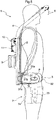
- the operation arms 73 are supported in a state capable of swinging around a pivot axis P in the left-right direction. That is, the operation arms 73 can swing in the vertical direction. Further, the leg assist device 7 can cause the operation arms 73 to swing in the vertical direction by driving the leg electric motor.
- leg holding portions 74 are supported by the operation arms 73. As shown in FIGS. 3 and 4 , the leg holding portions 74 are fitted to the thighs of the worker.
- the leg holding portions 74 are belt-like members. Also, as shown in FIG. 1 , each leg holding portion 74 is provided with a hook-and-loop fastener 74a capable of joining end portions of the leg holding portion 74 to each other. By bringing the hook-and-loop fastener 74a into an engaged state, the leg holding portion 74 has an annular shape as shown in FIG. 3 .
- the worker When fitting the leg holding portion 74 to the thigh, the worker first detaches the hook-and-loop fastener 74a. Then, the worker winds the leg holding portion 74 around the thigh, and brings the hook-and-loop fastener 74a into an engaged state. In this way, the leg holding portion 74 is fitted to the thigh of the worker. Note that in FIGS. 3 to 5 , the body portion 2 and the leg holding portions 74 have been fitted to the worker.
- the pivot axis P is positioned lower than the stepped portion 31b. Also, the pivot axis P is positioned higher than the lower end portion of the waist belt 3. Note that the position of the pivot axis P may be a position at the same height as the stepped portion 31b.
- the pivot axis P of the operation arms 73 is positioned at the same height as the stepped portion 31b or lower than the stepped portion 31b. Also, in a state where the body portion 2 and the leg holding portions 74 have been fitted to the worker, the pivot axis P is positioned higher than the lower end portion of the waist belt 3.
- the height of the pivot axis P of the operation arms 73 is approximately equal to the height of a vertical swinging center (hip joint) Q of the thigh of the worker.
- leg assist device 7 movement of the leg assist device 7 will be described. Below, as an example, a case is described where a worker places a package that has been placed on the floor onto a truck bed.
- the winch device 10 is stopped. Also, at this time, the leg electric motor is in a free rotation state. That is, when the worker is walking or the worker bends their knees to drop the waist (when crouching), if the worker is not pushing either the raising switch 61 or the lowering switch 62, the operation arms 73 swing around the pivot axis P following movement of the thighs of the worker. Accordingly, movement of the worker is not hindered.
- the winch electric motor 11 is provided with an electromagnetic brake (not shown). When rotationally driving the winch electric motor 11, the electromagnetic brake is in a released state. Also, when the winch electric motor 11 is stopped or is not energized, the electromagnetic brake is in a braking state.
- the worker holds the right (left) hand portion 6 with their right hand (left hand), and attaches the left-right pair of hand portions 6 to the package.
- the leg electric motor drives in a direction that causes the operation arms 73 to swing downward.
- the driving force of the leg electric motor acts on the thighs of the worker through the operation arms 73 and the leg holding portions 74. That is, the front side of the thighs of the worker are pushed downward. Therefore, standing of the worker is assisted.
- the winch wires 5 are wound up by rotational driving of the winch electric motor 11.
- the winch electric motor 11 stops.
- rising of the left-right pair of hand portions 6 stops.
- the worker walks to the vicinity of the truck bed where the package is to be placed.
- the worker arrives near the truck bed and the worker performs pushing operation of the lowering switch 62, the winch wires 5 are unwound by rotational driving of the winch electric motor 11.
- the left-right pair of hand portions 6 descend.
- the worker can place the package on the truck bed.
- the initial state is reestablished. Then, the worker can perform similar work for a subsequent package.
- the assist suit 1 includes the leg assist device 7 that extends to the front side from the body portion 2 through areas beside the worker, and assists the worker in a standing movement by exerting a pushing action on the thighs of the worker from the front side.
- the leg assist device 7 has the operation arms 73 supported by the body portion 2 in a state capable of swinging in the vertical direction, and the leg holding portions 74 supported by the operation arms 73 and fitted to the thighs of the worker, and is configured such that by causing the operation arms 73 to swing in the vertical direction, the leg assist device 7 acts on the thighs of the worker through the leg holding portions 74.
- respective upper side end portions 8a of the left-right pair of shoulder belts 8 are supported by an upper side portion of the body portion 2.
- respective lower side end portions 8b of the left-right pair of shoulder belts 8 are supported by the waist belt 3. That is, the lower side end portions 8b are supported by the lower side portion of the body portion 2 through the waist belt 3. Also, the lower side end portions 8b are supported by the left and right end portions of the body portion 2 through the waist belt 3.
- the upper side end portions 8a of the left-right pair of shoulder belts 8 are supported by the upper side portion of the body portion 2.
- the lower side end portions 8b of the left-right pair of shoulder belts 8 are supported by the lower side portion of the body portion 2.
- the lower side end portions 8b of the left-right pair of shoulder belts 8 are supported by the left and right end portions of the body portion 2.
- the upper side end portions 8a of the left-right pair of shoulder belts 8 are supported by a center portion in the left-right direction of the body portion 2.
- an interval X between the upper side end portions 8a in the left-right pair of shoulder belts 8 is narrower than an interval Y between the lower side end portions 8b in the left-right pair of shoulder belts 8.
- the upper side end portions 8a of the left-right pair of shoulder belts 8 may be in contact with each other. That is, the size of the interval X may be 0 (zero).
- the height where the waist belt 3 is wound easily matches the height assumed by the designer. That is, the positions of the hand portions 6 and the leg assist device 7 also easily match the height assumed by the designer.
- an assist suit includes a body portion 101, a left-right pair of arm portions 102, a left-right pair of hand portions 103, a winch device 104, and a left-right pair of leg assist devices 105.
- the body portion 101 is fitted to the back of a worker.
- a waist belt 106 wound around the waist of the worker and a left-right pair of shoulder belts 107 hooked over the shoulders of the worker are attached to the body portion 101.
- the waist belt 106 is wound around the waist of the worker, and the left-right pair of shoulder belts 107 are hooked over the shoulders of the worker to fit the body portion 101 to the back of the worker.
- a battery 108 serving as main power and a control portion 109 are provided in the body portion 101.
- the winch device 104 is attached to a rear face of the body portion 101.
- the winch device 104 is capable of winding and unwinding winch wires 110.
- the winch device 104 includes a reel case 111, a winch motor 112, and a transmission case 113.
- a reel 104A (see FIG. 9 ) around which the winch wires 110 are wound is built into the reel case 111.
- the winch motor 112 rotationally drives the reel 104A.
- a transmission mechanism (not shown) that transmits the rotational driving force of the winch motor 112 to the reel 104A is built into the transmission case 113.
- the winch motor 112 has a motor brake (not shown).
- the motor brake is in a released state when the winch motor 112 is being driven, and is in a braking state when the winch motor 112 is stopped. In the present embodiment, when the winch motor 112 is stopped, the winch wires 110 are held by the motor brake such that the winch wires 110 are not rewound.
- the arm portions 102 extend to the front side from the body portion 101 through an area above the worker. Specifically, the arm portions 102 extend to the front side in a posture inclined upwardly frontward from both left and right side portions of the body portion 101 through an area above the shoulder portions of the worker. The left-right interval between the left-right pair of arm portions 102 gradually increases as the arm portions 102 extend to the front side.
- a pulley 114 around which a winch wire 110 is wound is provided at the tip end portion of each arm portion 102. The winch wire 110 hangs from the tip end portion of the arm portion 102 in a state wound around the pulley 114.
- the hand portions 103 are suspended from the tip end portions of the arm portions 102 through the winch wires 110.
- the hand portions 103 serve as handles for the worker in a state where the hand portions 103 have been attached to an object to be lifted (not shown).
- a manually operated raising switch 115 is provided in the right side hand portion 103, and a manually operated lowering switch 116 is provided in the left side hand portion 103.
- the raising switch 115 is a resetting-type switch, and issues a command signal only while the worker is performing pushing operation of the raising switch 115.
- the worker can perform pushing operation of the raising switch 115 with their right hand thumb in a state where the worker is holding the right side hand portion 103 with their right hand.
- the lowering switch 116 is a resetting-type switch, and issues a command signal only while the worker is performing pushing operation of the lowering switch 116.
- the worker can perform pushing operation of the lowering switch 116 with their left hand thumb in a state where the worker is holding the left side hand portion 103 with their left hand.
- the leg assist devices 105 assist a movement in which the worker stands up by acting on the thighs of the worker.
- the leg assist devices 105 include a leg assist motor 117, a transmission case 118, a leg arm 119, and a leg belt 120.
- the leg assist motor 117 drives the leg arm 119 to swing.
- the transmission case 118 extends to the front side from the body portion 101 through areas beside the worker (the waist of the worker).
- a transmission mechanism (not shown) that transmits the swing driving force of the leg assist motor 117 to the leg arm 119 is built into the transmission case 118.
- the leg arm 119 is supported by the front end portion of the transmission case 118 such that the leg arm 119 can swing around an axis X that extends in the left-right direction.
- the leg belt 120 which is wound around a thigh of the worker, is attached to the leg arm 119.
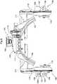
- a left switch disposing portion 125L is provided in a lateral outer side portion on the left side of the transmission case 118.
- an upper/lower limit value change switch 126 (corresponding to an "operation portion", a “second operation portion”, a “leg assist change command operation portion”, and a “winch assist change command operation portion” according to the present invention) and an upper/lower limit value display portion 27. That is, the upper/lower limit value change switch 126 and the upper/lower limit value display portion 127 are disposed in a portion that is positioned on the left side of the worker in the leg assist device 105 on the left side.
- the upper/lower limit value change switch 126 and the upper/lower limit value display portion 127 will be described in detail later.
- a right switch disposing portion 125R is provided in a lateral outer side portion on the right side of the transmission case 118.
- a power switch 128 (corresponding to an "operation portion”, a "first operation portion”, and a “power operation portion” according to the present invention)
- a drive mode switching switch 129 (corresponding to an "operation portion” and a “first operation portion” according to the present invention)
- a power display portion 130 and a drive mode display portion 131. That is, the power switch 128, the drive mode switching switch 129, the power display portion 130, and the drive mode display portion 131 are disposed in a portion that is positioned on the right side of the worker in the leg assist device 105 on the right side. Also, the power switch 128, the drive mode switching switch 129, the power display portion 130, and the drive mode display portion 131 will be described in detail later.
- an operation range R1 of the winch device 104 corresponds to a raising/lowering range of the hand portions 103.
- the upper limit value of the operation range R1 of the winch device 104 is represented as a winch assist upper limit value U1
- the lower limit value of the operation range R1 of the winch device 104 is represented as a winch assist lower limit value L1.
- an area on the upper limit side relative to a center C1 in the operation range R1 of the winch device 104 is represented as a winch assist upper limit side area R1U
- an area on the lower limit side relative to the center C1 in the operation range R1 of the winch device 104 is represented as a winch assist lower limit side area R1L.
- the operation range R1 of the winch device 104 shown in FIG. 6 is an example, and may be changed somewhat.
- An operation range R2 of the leg assist devices 105 corresponds to a swinging range of the leg arm 119.
- the upper limit value of the operation range R2 of the leg assist devices 105 is represented as a leg assist upper limit value U2
- the lower limit value of the operation range R2 of the leg assist devices 105 is represented as a leg assist lower limit value L2.
- an area on the upper limit side relative to a center C2 in the operation range R2 of the leg assist devices 105 is represented as a leg assist upper limit side area R2U
- an area on the lower limit side relative to the center C2 in the operation range R2 of the leg assist devices 105 is represented as a leg assist lower limit side area R2L.
- the operation range R2 of the leg assist devices 105 shown in FIG. 6 is an example, and may be changed somewhat.
- the assist suit in order to control operation of the winch device 104 and the leg assist devices 105, includes a control portion 109, potentiometers 132, 133, and 134, rotation speed sensors 135, 136 and 137, a winch motor driver 122, a left leg assist motor driver 123, and a right leg assist motor driver 124.
- the control portion 109, the winch motor driver 122, the left leg assist motor driver 123, and the right leg assist motor driver 124 can communicate with each other by in-vehicle communications such as CAN communications.
- the raising switch 115, the lowering switch 116, the upper/lower limit value change switch 126, the power switch 128, the drive mode switching switch 129, the upper/lower limit value display portion 127, the power display portion 130, and the drive mode display portion 131 are connected to the control portion 109.
- the potentiometer 132 detects the swing angle of the left side leg arm 119.
- the potentiometer 133 detects the swing angle of the right side leg arm 119.
- the potentiometer 134 detects the rotation angle of the reel 104A.
- the rotation speed sensor 135 detects the rotation speed of the left side leg assist motor 117.
- the rotation speed sensor 136 detects the rotation speed of the right side leg assist motor 117.
- the rotation speed sensor 137 detects the rotation speed of the winch motor 112.
- the winch motor driver 122 receives a drive command of the control portion 109 (a drive portion 139) and drives the winch motor 112 according to the driving command.
- the left leg assist motor driver 123 receives the drive command of the control portion 109 (the drive portion 139) and drives the left side leg assist motor 117 according to the drive command.
- the right leg assist motor driver 124 receives the drive command of the control portion 109 (the drive portion 139) and drives the right side leg assist motor 117 according to the drive command.
- the control portion 109 includes a power portion 138, the drive portion 139, a drive mode switching portion 140, a leg assist upper/lower limit value setting portion 141, a winch assist upper/lower limit value setting portion 142, a leg assist malfunction determination portion 143, and a winch assist malfunction determination unit 144.
- the power portion 138 supplies electric power of the battery 108 to various devices according to commands from the power switch 128.
- the drive portion 139 issues drive commands to the winch motor driver 122, the left leg assist motor driver 123, and the right leg assist motor driver 124 in response to commands from the raising switch 115 or the lowering switch 116.
- the drive mode switching portion 140 switches the drive mode of the assist suit according to a command from the drive mode switching switch 129.
- drive modes of the assist suit there are assumed an advanced mode suitable for use by an advanced user, a beginner mode suitable for use by a beginner, and a practice mode suitable for practicing.
- the drive modes of the assist suit are not limited to these.
- the leg assist upper/lower limit value setting portion 141 sets the leg assist upper limit value U2 and the leg assist lower limit value L2.
- the leg assist upper/lower limit value setting portion 141 has a mode (a leg assist upper/lower limit value change mode) in which it is possible to change the leg assist upper limit value U2 and the leg assist lower limit value L2.
- the winch assist upper/lower limit value setting portion 142 sets the winch assist upper limit value U1 and the winch assist lower limit value L1.
- the winch assist upper/lower limit value setting portion 142 has a mode (a winch assist upper/lower limit value change mode) in which it is possible to change the winch assist upper limit value U1 and the winch assist lower limit value L1.
- the leg assist malfunction determination portion 143 calculates (estimates) the swing angles of the leg arms 119 based on the detection values of the rotation speed sensors 135 and 136, and compares the calculated swing angles with the detection values of the potentiometers 132 and 133. In a case where the values are different, it is judged that the potentiometers 132 and 133 have a malfunction, and assistance by the leg assist devices 105 is stopped.
- the winch assist malfunction determination portion 144 calculates (estimates) the rotation angle of the reel 104A based on the detection value of the rotation speed sensor 137, and compares the calculated rotation angle with the detection value of the potentiometer 134. In a case where the values are different, it is judged that the potentiometer 134 has a malfunction, and assistance by the winch device 104 is stopped.
- the upper/lower limit value change switch 126 is a manually operated switch that commands the leg assist upper/lower limit value setting portion 141 to change the leg assist upper limit value U2 and the leg assist lower limit value L2, and commands the winch assist upper/lower limit value setting portion 142 to change the winch assist upper limit value U1 and the winch assist lower limit value L1.
- the power switch 128 is a manually operated switch that switches main power (supply of electric power from the battery 108) on/off.
- the drive mode switching switch 129 is a manually operated switch that switches the drive mode of the assist suit.
- the upper/lower limit value display portion 127 is provided with LEDs (for example, two) (see FIG. 8 ), and according to the leg assist upper/lower limit value change mode or the winch assist upper/lower limit value change mode, some LED among the two LEDs lights up.
- the power display portion 130 is provided with an LED (for example, one) (see FIG. 8 ), and the LED lights up according to on/off operation of the power switch 128.
- the drive mode display portion 131 is provided with LEDs (for example, three) (see FIG. 8 ), and some LED among the three LEDs lights up according to the drive mode of the assist suit.
- the control portion 109 (the drive portion 139) sends a drive command to the motor drivers 122, 123, and 124
- the motor drivers 122, 123, and 124 that received the drive command then drive the motors 112, 117 and 117, and also send a reply to the control portion 109 with the content of the drive command and the motor drive status (torque and rotation speed).
- the control portion 109 transmits a drive stop command to the motor drivers 122, 123, and 124, and also does not accept operation from the worker.
- the motor drivers 122, 123, and 124 receiving a drive command from the control portion 109 (the drive portion 139) and driving the motors 12, 17 and 17 according to the drive command, the period in which the drive command is sent from the control portion 9 (the drive portion 139) to the motor drivers 122, 123, and 124 is set in advance.
- the motor drivers 122, 123, and 124 judge that there is a malfunction and do not drive the motors 112, 117 and 117.
- the motor drivers 122, 123, and 124 may gradually decrease the output of the motors 112, 117 and 117.
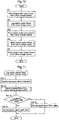
- leg assist upper/lower limit value change mode and the winch assist upper/lower limit value change mode will be described with reference to FIGS. 10 to 12 .
- the mode is switched from the initial state to the leg assist upper/lower limit value change mode (S2).
- the LED corresponding to the leg assist upper/lower limit value change mode in the upper/lower limit value display portion 127 is lit.
- the mode is switched from the leg assist upper/lower limit value change mode to the winch assist upper/lower limit value change mode (S4).
- the LED corresponding to the leg assist upper/lower limit value change mode in the upper/lower limit value display portion 127 is turned off, and the LED corresponding to the winch assist upper/lower limit value change mode in the upper/lower limit value display portion 127 is lit.
- the mode returns from the winch assist upper/lower limit value change mode to the initial state. Along with this, all the LEDs of the upper/lower limit value display portion 127 are turned off.
- the worker swings the leg arms 119 to an arbitrary swing position (S2-1).
- the worker may perform pushing operation of the raising switch 115 or the lowering switch 116 to swing the leg arms 119 using the leg assist motors 117, or may manually swing the leg arms 119.
- the leg assist upper/lower limit value setting portion 141 judges whether the swing position of the leg arms 119 at the time when the upper/lower limit value change switch 126 was pushed belongs to either of the leg assist upper limit side area R2U and the leg assist lower limit side area R2L (S2-3).
- the leg assist upper/lower limit value setting portion 141 sets the swing position of the leg arms 119 at the time when the upper/lower limit value change switch 126 was pushed to the leg assist upper limit value U2 (S2-4).
- the previous leg assist upper limit value U2 is overwritten with the present leg assist upper limit value U2.
- the leg assist upper/lower limit value setting portion 141 sets the swing position of the leg arms 119 at the time when the upper/lower limit value change switch 126 was pushed to the leg assist lower limit value L2 (S2-5).
- the previous leg assist lower limit value L2 is overwritten with the present leg assist lower limit value L2.
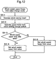
- the worker rotates the reel 104A to an arbitrary rotation position (S4-1).
- the worker may perform pushing operation of the raising switch 115 or the lowering switch 116 to rotate the reel 104A using the winch motor 112.
- the winch assist upper/lower limit value setting portion 142 judges whether the rotation position of the reel 104A at the time when the upper/lower limit value change switch 126 was pushed belongs to either of the winch assist upper limit side area R1U and the winch assist lower limit side area R1L (S4-3).
- the winch assist upper/lower limit value setting portion 142 sets the rotation position of the reel 104A at the time when the upper/lower limit value change switch 126 was pushed to the winch assist upper limit value U1 (S4-4).
- the previous winch assist upper limit value U1 is overwritten with the present winch assist upper limit value U1.
- the winch assist upper/lower limit value setting portion 42 sets the rotation position of the reel 104A at the time when the upper/lower limit value change switch 126 was pushed to the winch assist lower limit value L1 (S4-5).
- the previous winch assist lower limit value L1 is overwritten with the present winch assist lower limit value L1.
Landscapes
- Engineering & Computer Science (AREA)
- Mechanical Engineering (AREA)
- Robotics (AREA)
- Health & Medical Sciences (AREA)
- Life Sciences & Earth Sciences (AREA)
- Pain & Pain Management (AREA)
- Structural Engineering (AREA)
- Epidemiology (AREA)
- Geology (AREA)
- Physical Education & Sports Medicine (AREA)
- Rehabilitation Therapy (AREA)
- Animal Behavior & Ethology (AREA)
- General Health & Medical Sciences (AREA)
- Public Health (AREA)
- Veterinary Medicine (AREA)
- Manipulator (AREA)
Abstract
Description
- The present invention relates to an assist suit that is used fitted to a worker, and assists movement of the worker.
- As the sort of assist suit mentioned above, for example, an assist suit described in
Patent Document 1 is already known. The assist suit described inPatent Document 1 includes a body portion fitted to the back of a worker, and a waist belt (an "attachment belt" in Patent Document 1) that extends from the body portion and is wound around the waist of the worker to fit the body portion to the worker. - Also, the assist suit described in
Patent Document 1 has arm portions ("upper arm portions" in Patent Document 1) that extend to the front side from the body portion through an area above the worker, hand portions suspended from tip end portions of the arm portions through winch wires ("wires" in Patent Document 1) and serving as handles for the worker in a state where the hand portions have been attached to an object to be lifted, and a winch device (a "drive device" in Patent Document 1) capable of winding and unwinding the winch wires. - Also, the assist suit described in
Patent Document 1 is provided with a leg assist device (a "leg action portion" in Patent Document 1) that extends to the front side from the body portion through areas beside the worker, and assists the worker in a standing movement by exerting a pushing action on a thigh of the worker from the front side. - Also, for example, in a case where the worker crouches to lift up a package on the floor, according to the above configuration, a standing movement and a movement to lift the package are assisted by the assist suit.
- Also, as the sort of assist suit mentioned above, for example, an assist suit described in Patent Document 2 (a "power assist suit" in that document) is already known. The power assist suit described in
Patent Document 2 includes lower leg parts that can be fitted to lower limbs, and upper limb parts that can be fitted to upper limbs. -
- Patent Document 1:
JP 2015-182832A - Patent Document 2:
JP 2015-47313A - In the assist suit described in
Patent Document 1, when the worker winds the waist belt around their own waist, the waist belt may be wound at a position higher or lower than the height assumed by the designer. In that case, the positions of the hand portions and the leg assist device also are at a position higher or lower than the height assumed by the designer. As a result, the worker may feel uncomfortable about the positions of the hand portions and the leg assist device, or movement may be insufficiently assisted. - In view of the above problems, there are demands for an assist suit that allows a situation where a worker feels uncomfortable about the positions of the hand portions and the leg assist device, or a situation where a movement is insufficiently assisted, to easily be avoided.
- Also, in the assist suit described in
Patent Document 2, a manually operated operation portion (an "operation switch" in that document) is positioned on the back of the worker in an upper limb part, so in a state where the worker is wearing the assist suit, it is difficult for the worker to reach the operation portion with their hand, and therefore it is not easy to manually operate the operation portion. - In view of the above circumstances, there are demands for an assist suit in which an operation portion can easily be manually operated.
- In a characteristic configuration, the present invention includes:
- a body portion to be fitted to the back of a worker;
- a waist belt that extends from the body portion and is wound around the waist of the worker to fit the body portion to the worker;
- an arm portion that extends to a front side from the body portion through an area above the worker;
- a hand portion suspended from a tip end portion of the arm portion through a winch wire, and serving as a handle for the worker in a state where the hand portion has been attached to an object to be lifted;
- a winch device capable of winding and unwinding the winch wire; and
- a leg assist device that extends to the front side from the body portion through an area beside the worker, and assists the worker in a standing movement by exerting a pushing action on a thigh of the worker from the front side;
- wherein a back surface contact portion of the waist belt that contacts the back surface of the worker is provided with a positioning mechanism that prescribes the position where the waist belt is wound.
- According to the present invention, due to the positioning mechanism provided in the back surface contact portion, the height where the waist belt is wound easily matches the height assumed by the designer. That is, the positions of the hand portion and the leg assist device also easily match the height assumed by the designer.
- Therefore, according to the present invention, a situation where a worker feels uncomfortable about the positions of the hand portion and the leg assist device, or a situation where a movement is insufficiently assisted, are easily avoided.
- Further, in the present invention, it is preferable that the positioning mechanism is a recessed portion that is recessed in a belt thickness direction formed from an intermediate portion to a lower end portion in a vertical direction of the back surface contact portion.
- According to this configuration, the worker can obtain a feeling of good fit in a state with the recessed portion contacting the worker's buttocks and a portion on the upper side relative to the recessed portion contacting the worker's waist. As a result, according to this configuration, the worker easily winds the waist belt at a height where the recessed portion contacts the buttocks and the portion on the upper side relative to the recessed portion contacts the waist. Therefore, the recessed portion functions as a positioning mechanism.
- Therefore, according to the above configuration, a positioning mechanism can be provided by a simple configuration in which merely the recessed portion is provided.
- Further, in the present invention, it is preferable that a stepped portion is formed between the recessed portion in the back surface contact portion and a portion on an upper side relative to the recessed portion.
- The weight of a package and the assist suit are mainly applied to the waist belt. Therefore, it is assumed that the height of the waist belt gradually drops during work.
- Here, according to the above configuration, the stepped portion catches on the upper portion of the buttocks of the worker. Therefore, it is difficult for the height of the waist belt to drop during work.
- Further, in the present invention, it is preferable that the leg assist device has an operation arm supported by the body portion in a state capable of swinging in the vertical direction, and a leg holding portion supported by the operation arm and fitted to a thigh of the worker, and is configured such that by causing the operation arm to swing in the vertical direction, the leg assist device acts on the thigh of the worker through the leg holding portion, and
in a state where the body portion and the leg holding portion have been fitted to the worker, a pivot axis of the operation arm is positioned at the same height as the stepped portion or lower than the stepped portion. - In a state where the waist belt has been wound at the height prescribed by the recessed portion, the vertical swinging center (hip joint) of the thigh of the worker is easily positioned at the same height as the stepped portion or lower than the stepped portion. Furthermore, according to the above configuration, the pivot axis of the operation arm is also positioned at the same height as the stepped portion or lower than the stepped portion.
- That is, according to the above configuration, the height of the pivot axis of the operation arm easily becomes the same as the height of the vertical swinging center of the thigh of the worker. Also, in a case where the height of the pivot axis of the operation arm is the same as the vertical swinging center of the thigh of the worker, the leg assist device can act favorably on the thigh of the worker.
- Therefore, according to the above configuration, the leg assist device easily acts favorably on the thigh of the worker.
- Further, in the present invention, it is preferable that in a state where the body portion and the leg holding portion have been fitted to the worker, the pivot axis is positioned higher than a lower end portion of the waist belt.
- In a state where the waist belt has been wound at the height prescribed by the recessed portion, the vertical swinging center (hip joint) of the thigh of the worker is easily positioned higher than the lower end portion of the waist belt. Furthermore, according to the above configuration, the pivot axis of the operation arm is also positioned higher than the lower end portion of the waist belt.
- That is, according to the above configuration, the height of the pivot axis of the operation arm easily becomes the same as the height of the vertical swinging center of the thigh of the worker. Also, in a case where the height of the pivot axis of the operation arm is the same as the vertical swinging center of the thigh of the worker, the leg assist device can act favorably on the thigh of the worker.
- Therefore, according to the above configuration, the leg assist device easily acts favorably on the thigh of the worker.
- Further, in the present invention, it is preferable that the positioning mechanism is formed spanning across left and right ends of the back surface contact portion.
- According to this configuration, for example, a wide and stable positioning mechanism is more easily formed than in a case where a positioning mechanism is formed only at the left or right end portion of the back surface contact portion.
- Further, in the present invention, it is preferable that a left-right pair of shoulder belts hooked over both shoulders of the worker are provided;
wherein upper side end portions of the left-right pair of shoulder belts are supported by an upper side portion of the body portion,
lower side end portions of the left-right pair of shoulder belts are supported by a lower side portion of the body portion, and
an interval between the upper side end portions in the left-right pair of shoulder belts is narrower than an interval between the lower side end portions in the left-right pair of shoulder belts. - In a state where the left-right pair of shoulder belts have been hooked over both shoulders of the worker, as the interval between the worker's neck and the left-right pair of shoulder belts increases, the shoulder belts can shift more to the left or right. When the shoulder belts shift greatly to the left or right, inconveniences such as the body portion tilting greatly or the shoulder belts separating from the shoulders of the worker may occur.
- Here, according to the above configuration, in a state where the left-right pair of shoulder belts have been hooked over both shoulders of the worker, the interval between the worker's neck and the left-right pair of shoulder belts is comparatively small. Therefore, the width in which the shoulder belts can shift to the left or right is small. Accordingly, it is unlikely that inconveniences such as the body portion tilting greatly or the shoulder belts separating from the shoulders of the worker will occur.
- Further, in the present invention, it is preferable that the upper side end portions of the left-right pair of shoulder belts are supported by a center portion in a left-right direction of the body portion, and
the lower side end portions of the left-right pair of shoulder belts are supported by left and right end portions of the body portion. - According to this configuration, the upper side end portions of the left-right pair of shoulder belts are supported by the center portion in the left-right direction of the body portion, so in a state where the left-right pair of shoulder belts have been hooked over both shoulders of the worker, the interval between the worker's neck and the left-right pair of shoulder belts is particularly small. Accordingly, it is particularly unlikely that inconveniences such as the body portion tilting greatly or the shoulder belts separating from the shoulders of the worker will occur.
- Moreover, because the lower side end portions of the left-right pair of shoulder belts are supported by the left and right end portions of the body portion, the interval between the left-right pair of shoulder belts increases in the downward direction. Therefore, the worker can easily pass both arms through the left-right pair of shoulder belts. Also, the worker can easily hook the left-right pair of shoulder belts over both shoulders.
- In a characteristic configuration, the present invention includes:
- a body portion to be fitted to the back of a worker; and
- a leg assist device that extends to a front side from the body portion through an area beside the worker, and assists the worker in a standing movement by exerting a pushing action on a thigh of the worker;
- wherein a manually operated operation portion is disposed in a portion positioned beside the worker in the leg assist device.
- According to this configuration, the operation portion is positioned beside the worker, so in a state where the worker is wearing the assist suit, it is easy for the worker to reach the operation portion with their hand, and therefore it is easy to manually operate the operation portion.
- Further, in the present invention, it is preferable that a left-right pair of the leg assist devices are provided;
wherein a first operation portion is disposed as the operation portion in a portion positioned beside the worker in a right side leg assist device among the left-right pair of leg assist devices, and
a second operation portion is disposed as the operation portion in a portion positioned beside the worker in a left side leg assist device among the left-right pair of leg assist devices. - According to this configuration, the first operation portion is positioned to the right side of the worker and the second operation portion is positioned to the left side of the worker. Here, if the first operation portion is adopted as an operation portion having a comparatively high frequency of use and the second operation portion is adopted as an operation portion having a comparatively low frequency of use, it is possible to realize a layout suitable for a right-handed worker.
- Further, in the present invention, it is preferable that the operation portion is a power operation portion that switches main power on or off.
- According to this configuration, the power operation portion, which has a comparatively high frequency of use, is positioned beside the worker, so in a state where the worker is wearing the assist suit, it is easy for the worker to reach the power operation portion with their hand, and therefore it is easy to manually operate the power operation portion.
- Further, in the present invention, it is preferable that there are provided:
- a leg assist upper/lower limit value setting portion that sets a leg assist upper limit value that is an upper limit value of an operation range of the leg assist device, and a leg assist lower limit value that is a lower limit value of the operation range of the leg assist device; and
- a manually operated leg assist change command operation portion that commands the leg assist upper/lower limit value setting portion to change the leg assist upper limit value and the leg assist lower limit value.
- According to this configuration, it is possible for the worker to change the leg assist upper limit value and the leg assist lower limit value according to their own body type or working manner.
- Further, in the present invention, it is preferable that when the worker manually operates the leg assist change command operation portion in a state where the worker has operated the leg assist device to an arbitrary operation position, the leg assist upper/lower limit value setting portion sets the operation position of the leg assist device at the time when the leg assist change command operation portion was manually operated to the leg assist upper limit value or the leg assist lower limit value.
- According to this configuration, the operation position of the leg assist device is set to the leg assist upper limit value or the leg assist lower limit value after the worker actually operates the leg assist device and confirms that operation position, so it is possible for the worker to easily change the leg assist upper limit value or the leg assist lower limit value according to their own body type or working manner.
- Further, in the present invention, it is preferable that an area on an upper limit side in the operation range of the leg assist device is represented as a leg assist upper limit side area, and an area on a lower limit side in the operation range of the leg assist device is represented as a leg assist lower limit side area, and
the leg assist upper/lower limit value setting portion,
if the operation position of the leg assist device belongs to the leg assist upper limit side area, sets the operation position of the leg assist device at the time when the leg assist change command operation portion was manually operated to the leg assist upper limit value, and
if the operation position of the leg assist device belongs to the leg assist lower limit side area, sets the operation position of the leg assist device at the time when the leg assist change command operation portion was manually operated to the leg assist lower limit value. - According to this configuration, when the worker manually operates the leg assist change command operation portion in a state where the worker has operated the leg assist device to an arbitrary operation position, the leg assist upper/lower limit value setting portion automatically judges whether the operation position of the leg assist device at the time when the leg assist change command operation portion was manually operated should be set to the leg assist upper limit value or to the leg assist lower limit value, and then sets the operation position of the leg assist device at the time when the leg assist change command operation portion was manually operated to the leg assist upper limit value or the leg assist lower limit value. As a result, it is possible to easily change the leg assist upper limit value or the leg assist lower limit value, without the nuisance of the worker judging whether the operation position of the leg assist device at the time when the leg assist change command operation portion was manually operated should be set to the leg assist upper limit value or to the leg assist lower limit value.
- Further, in the present invention, it is preferable that there are provided:
- an arm portion that extends to a front side from the body portion through an area above the worker;
- a hand portion suspended from a tip end portion of the arm portion through a winch wire, and serving as a handle for the worker in a state where the hand portion has been attached to an object to be lifted;
- a winch device capable of winding and unwinding the winch wire;
- a winch assist upper/lower limit value setting portion that sets a winch assist upper limit value that is an upper limit value of an operation range of the winch device, and a winch assist lower limit value that is a lower limit value of the operation range of the winch device; and
- a manually operated winch assist change command operation portion that commands the winch assist upper/lower limit value setting portion to change the winch assist upper limit value and the winch assist lower limit value.
- According to this configuration, it is possible for the worker to change the winch assist upper limit value and the winch assist lower limit value according to their own body type or working manner.
- Further, in the present invention, it is preferable that when the worker manually operates the winch assist change command operation portion in a state where the worker has operated the winch device to an arbitrary operation position, the winch assist upper/lower limit value setting portion sets the operation position of the winch device at the time when the winch assist change command operation portion was manually operated to the winch assist upper limit value or the winch assist lower limit value.
- According to this configuration, the operation position of the winch device is set to the winch assist upper limit value or the winch assist lower limit value after the worker actually operates the winch device and confirms that operation position, so it is possible for the worker to easily change the winch assist upper limit value or the winch assist lower limit value according to their own body type or working manner.
- Further, in the present invention, it is preferable that an area on an upper limit side in the operation range of the winch device is represented as a winch assist upper limit side area, and an area on a lower limit side in the operation range of the winch device is represented as a winch assist lower limit side area, and
the winch assist upper/lower limit value setting portion,
if the operation position of the winch device belongs to the winch assist upper limit side area, sets the operation position of the winch device at the time when the winch assist change command operation portion was manually operated to the winch assist upper limit value, and
if the operation position of the winch device belongs to the winch assist lower limit side area, sets the operation position of the winch device at the time when the winch assist change command operation portion was manually operated to the winch assist lower limit value. - According to this configuration, when the worker manually operates the winch assist change command operation portion in a state where the worker has operated the winch device to an arbitrary operation position, the winch assist upper/lower limit value setting portion automatically judges whether the operation position of the winch device at the time when the winch assist change command operation portion was manually operated should be set to the winch assist upper limit value or to the winch assist lower limit value, and then sets the operation position of the winch device at the time when the winch assist change command operation portion was manually operated to the winch assist upper limit value or the winch assist lower limit value. As a result, it is possible to easily change the winch assist upper limit value or the winch assist lower limit value, without the nuisance of the worker judging whether the operation position of the winch device at the time when the winch assist change command operation portion was manually operated should be set to the winch assist upper limit value or to the winch assist lower limit value.
-
-
FIG. 1 is a perspective view showing the overall configuration of an assist suit according to a first embodiment. -
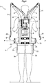
FIG. 2 is a front view showing the overall configuration of an assist suit according to a first embodiment. -
FIG. 3 is a side view showing a state where a worker is wearing an assist suit according to a first embodiment. -
FIG. 4 is a rear view showing a state where a worker is wearing an assist suit according to a first embodiment. -
FIG. 5 is a longitudinal cross-sectional view showing the structure of a back surface contact portion according to a first embodiment. -
FIG. 6 is a right side view showing a state where a worker is wearing an assist suit according to a second embodiment. -
FIG. 7 is a rear view showing a state where a worker is wearing an assist suit according to a second embodiment. -
FIG. 8 is a plan view showing an assist suit according to a second embodiment. -
FIG. 9 is a diagram showing control blocks according to a second embodiment. -
FIG. 10 is a diagram showing a control flow relating to a leg assist upper/lower limit value change mode and a winch assist upper/lower limit value change mode according to a second embodiment. -
FIG. 11 is a diagram showing a control flow relating to a leg assist upper/lower limit value change mode according to a second embodiment. -
FIG. 12 is a diagram showing a control flow relating to a winch assist upper/lower limit value change mode according to a second embodiment. - An embodiment for carrying out the present invention will be described with reference to the drawings. Note that in the following description, the front-rear direction, the left-right direction, and the up-down direction are described as follows. That is, in a state where the worker is wearing an
assist suit 1, viewed from the perspective of the worker, the front side is "front", the rear side is "rear", the right side is "right", the left side is "left", the upper side is "upper", and the lower side is "lower". -
FIGS. 1 and2 show the overall configuration of theassist suit 1 according to the present invention. Theassist suit 1 includes abody portion 2. Also, awaist belt 3 is extended from thebody portion 2. Thewaist belt 3 is supported at a lower side portion in thebody portion 2. Note that in the lower side portion of thebody portion 2, a portion supporting thewaist belt 3 spans across left and right end portions of thebody portion 2. - As shown in
FIG. 3 , thewaist belt 3 is wound around the waist of the worker to fit thebody portion 2 to the worker. Also, when thewaist belt 3 is wound around the waist of the worker, thebody portion 2 is in a state fitted to the back of the worker. - In this way, the
assist suit 1 includes thebody portion 2 fitted to the back of the worker, and thewaist belt 3 that extends from thebody portion 2 and is wound around the waist of the worker to fit thebody portion 2 to the worker. - Note that, as shown in
FIGS. 1 and2 , thewaist belt 3 includes an insertion-type buckle 32. When winding thewaist belt 3 around the waist, the worker first detaches the insertion-type buckle 32. Then, the worker winds thewaist belt 3 around the waist and couples the insertion-type buckle 32. In this way, thewaist belt 3 is kept in a state wound around the waist of the worker. - As shown in
FIGS. 1 and2 , theassist suit 1 includes a left-right pair ofarm portions 4. As shown inFIGS. 3 and4 , the left-right pair ofarm portions 4 extend to the front side from thebody portion 2 through an area above the shoulders of the worker. - In this way, the
assist suit 1 includes thearm portions 4 that extend to the front side from thebody portion 2 through an area above the worker. - Also, as shown in
FIGS. 2 to 4 ,hand portions 6 are suspended from tip end portions of each of the left-right pair ofarm portions 4 throughwinch wires 5. Thehand portions 6 are configured so as to be capable of being attached to an object to be lifted. Also, thehand portions 6 are configured so as to serve as handles for the worker in a state where thehand portions 6 have been attached to an object to be lifted. - In this way, the
assist suit 1 includes thehand portions 6 suspended from tip end portions of thearm portions 4 through thewinch wires 5, and serving as handles for the worker in a state where thehand portions 6 have been attached to an object to be lifted. - A raising
switch 61 is provided in thehand portion 6 on the right side. Also, a loweringswitch 62 is provided in thehand portion 6 on the left side. - As shown in
FIGS. 1 to 4 , awinch device 10 is attached to an upper portion of a rear face of thebody portion 2. Also, abattery 9 is attached below thewinch device 10. - The
winch wires 5 extend fromwinch device 10. Also, thewinch device 10 has a winchelectric motor 11. Thewinch device 10 is capable of winding and unwinding thewinch wires 5 using rotational driving of the winchelectric motor 11. - In this way, the
assist suit 1 includes thewinch device 10 capable of winding and unwinding thewinch wires 5. - Also, as shown in
FIGS. 1 to 4 , theassist suit 1 has a left-right pair ofshoulder belts 8 hooked over both shoulders of the worker. Note that the left-right pair ofshoulder belts 8 are pullout-type shoulder belts. - In a case where the worker has lifted a package using the
assist suit 1, the weight of the package and theassist suit 1 is mainly applied to thewaist belt 3. As a result, the worker can stably support the weight of the package and theassist suit 1 using the waist. Also, at this time, by the left-right pair ofshoulder belts 8, thebody portion 2 is prevented from separating from the back of the worker by falling backward. - As shown in
FIGS. 1 and2 , thewaist belt 3 has a backsurface contact portion 31. As shown inFIG. 5 , the backsurface contact portion 31 contacts the back surface of the worker in a state where thewaist belt 3 has been wound around the waist of the worker. - As shown in
FIGS. 1 ,2 , and5 , a bulgingportion 31a and a recessedportion 31c are formed in the backsurface contact portion 31. The bulgingportion 31a bulges in the belt thickness direction compared to the recessedportion 31c. In other words, the recessedportion 31c is recessed in the belt thickness direction compared to the bulgingportion 31a. Also, the recessedportion 31c is formed as a surface in the vertical direction. - The recessed
portion 31c is formed from an intermediate portion to a lower end portion in the vertical direction of the backsurface contact portion 31. Also, the bulgingportion 31a is formed on the upper side relative to the recessedportion 31c. Further, a steppedportion 31b is formed between the recessedportion 31c and the bulgingportion 31a. - In this way, the stepped
portion 31b is formed between the recessedportion 31c in the backsurface contact portion 31 and a portion on the upper side relative to the recessedportion 31c. - Here, when the worker winds the
waist belt 3 around the waist, as shown inFIG. 5 , the worker can obtain a feeling of good fit in a state with the recessedportion 31c contacting the worker's buttocks and the bulgingportion 31a contacting the worker's waist. As a result, the worker tends to wind thewaist belt 3 at a height where the recessedportion 31c contacts the buttocks and the bulgingportion 31a contacts the waist. That is, in the present embodiment, the recessedportion 31c functions as a positioning mechanism. - In this way, the back
surface contact portion 31 of thewaist belt 3 that contacts the back surface of the worker is provided with a positioning mechanism that prescribes the position where thewaist belt 3 is wound. Also, the positioning mechanism in the present embodiment is the recessedportion 31c that is recessed in the belt thickness direction formed from the intermediate portion to the lower end portion in the vertical direction of the backsurface contact portion 31. - Also, as shown in
FIG. 2 , the recessedportion 31c is formed spanning across the left and right ends of the backsurface contact portion 31. - In this way, the positioning mechanism in the present embodiment is formed spanning across the left and right ends of the back
surface contact portion 31. - As shown in
FIGS. 1 to 5 , theassist suit 1 includes aleg assist device 7. As shown inFIGS. 3 and4 , the leg assistdevice 7 extends to the front side from thebody portion 2 through areas beside the worker. Also, as shown inFIG. 1 , the leg assistdevice 7 has abase portion 71, a left-right pair oftransmission cases 72, a left-right pair ofoperation arms 73, and a left-right pair ofleg holding portions 74. - The
base portion 71 is supported under thebody portion 2 in a state capable of sliding in the left-right direction. A leg electric motor (not shown) is provided inside thebase portion 71. Also, the left-right pair oftransmission cases 72 are provided in a state extending frontward from both left and right end portions of thebase portion 71. Also, as shown inFIGS. 1 and2 , anoperation arm 73 is supported by each of the left-right pair oftransmission cases 72. That is, theoperation arms 73 are supported by thebody portion 2 through thebase portion 71 and thetransmission cases 72. - The
operation arms 73 are supported in a state capable of swinging around a pivot axis P in the left-right direction. That is, theoperation arms 73 can swing in the vertical direction. Further, the leg assistdevice 7 can cause theoperation arms 73 to swing in the vertical direction by driving the leg electric motor. - Also, the
leg holding portions 74 are supported by theoperation arms 73. As shown inFIGS. 3 and4 , theleg holding portions 74 are fitted to the thighs of the worker. - The
leg holding portions 74 are belt-like members. Also, as shown inFIG. 1 , eachleg holding portion 74 is provided with a hook-and-loop fastener 74a capable of joining end portions of theleg holding portion 74 to each other. By bringing the hook-and-loop fastener 74a into an engaged state, theleg holding portion 74 has an annular shape as shown inFIG. 3 . - When fitting the
leg holding portion 74 to the thigh, the worker first detaches the hook-and-loop fastener 74a. Then, the worker winds theleg holding portion 74 around the thigh, and brings the hook-and-loop fastener 74a into an engaged state. In this way, theleg holding portion 74 is fitted to the thigh of the worker. Note that inFIGS. 3 to 5 , thebody portion 2 and theleg holding portions 74 have been fitted to the worker. - As shown in
FIG. 5 , the pivot axis P is positioned lower than the steppedportion 31b. Also, the pivot axis P is positioned higher than the lower end portion of thewaist belt 3. Note that the position of the pivot axis P may be a position at the same height as the steppedportion 31b. - In this way, in a state where the
body portion 2 and theleg holding portions 74 have been fitted to the worker, the pivot axis P of theoperation arms 73 is positioned at the same height as the steppedportion 31b or lower than the steppedportion 31b. Also, in a state where thebody portion 2 and theleg holding portions 74 have been fitted to the worker, the pivot axis P is positioned higher than the lower end portion of thewaist belt 3. - Also, as shown in
FIG. 5 , the height of the pivot axis P of theoperation arms 73 is approximately equal to the height of a vertical swinging center (hip joint) Q of the thigh of the worker. - Here, movement of the leg assist
device 7 will be described. Below, as an example, a case is described where a worker places a package that has been placed on the floor onto a truck bed. - In a case where, in a state where the worker is wearing the
assist suit 1, the worker is not pushing either the raisingswitch 61 or the loweringswitch 62, thewinch device 10 is stopped. Also, at this time, the leg electric motor is in a free rotation state. That is, when the worker is walking or the worker bends their knees to drop the waist (when crouching), if the worker is not pushing either the raisingswitch 61 or the loweringswitch 62, theoperation arms 73 swing around the pivot axis P following movement of the thighs of the worker. Accordingly, movement of the worker is not hindered. - Next, in a case where the worker crouches and holds the package on the floor by hand, when the worker performs pushing operation of the lowering
switch 62, thewinch wires 5 are extended by rotational driving of the winchelectric motor 11. As a result, the left-right pair ofhand portions 6 descend. When the worker quits the pushing operation of the loweringswitch 62, the winchelectric motor 11 stops. As a result, descent of the left-right pair ofhand portions 6 stops. - The winch
electric motor 11 is provided with an electromagnetic brake (not shown). When rotationally driving the winchelectric motor 11, the electromagnetic brake is in a released state. Also, when the winchelectric motor 11 is stopped or is not energized, the electromagnetic brake is in a braking state. - As a result, in a state where the winch
electric motor 11 is stopped, even if the weight of the package is applied to the left-right pair ofhand portions 6, the left-right pair ofhand portions 6 do not descend. - Next, the worker holds the right (left)
hand portion 6 with their right hand (left hand), and attaches the left-right pair ofhand portions 6 to the package. In this state, when the worker performs pushing operation of the raisingswitch 61, the leg electric motor drives in a direction that causes theoperation arms 73 to swing downward. Also, the driving force of the leg electric motor acts on the thighs of the worker through theoperation arms 73 and theleg holding portions 74. That is, the front side of the thighs of the worker are pushed downward. Therefore, standing of the worker is assisted. - When the worker stands up, the package is lifted up from the floor. After the worker stands up while performing pushing operation of the raising
switch 61, when a sensor (not shown) detects that the direction of the left-right pair ofoperation arms 73 has reached approximately straight down, it is judged that the worker has completely stood up. Then, the leg electric motor enters the free rotation state. - Next, the
winch wires 5 are wound up by rotational driving of the winchelectric motor 11. Thus, the left-right pair ofhand portions 6 rise. Then, when the worker quits the pushing operation of the raisingswitch 61, the winchelectric motor 11 stops. As a result, rising of the left-right pair ofhand portions 6 stops. - Next, the worker walks to the vicinity of the truck bed where the package is to be placed. When the worker arrives near the truck bed and the worker performs pushing operation of the lowering
switch 62, thewinch wires 5 are unwound by rotational driving of the winchelectric motor 11. As a result, the left-right pair ofhand portions 6 descend. Then, the worker can place the package on the truck bed. - When the package is placed on the truck bed in the manner described above, the initial state is reestablished. Then, the worker can perform similar work for a subsequent package.
- In this way, the
assist suit 1 includes the leg assistdevice 7 that extends to the front side from thebody portion 2 through areas beside the worker, and assists the worker in a standing movement by exerting a pushing action on the thighs of the worker from the front side. - Also, in this way, the leg assist
device 7 has theoperation arms 73 supported by thebody portion 2 in a state capable of swinging in the vertical direction, and theleg holding portions 74 supported by theoperation arms 73 and fitted to the thighs of the worker, and is configured such that by causing theoperation arms 73 to swing in the vertical direction, the leg assistdevice 7 acts on the thighs of the worker through theleg holding portions 74. - As shown in
FIGS. 1 and2 , respective upperside end portions 8a of the left-right pair ofshoulder belts 8 are supported by an upper side portion of thebody portion 2. Also, respective lowerside end portions 8b of the left-right pair ofshoulder belts 8 are supported by thewaist belt 3. That is, the lowerside end portions 8b are supported by the lower side portion of thebody portion 2 through thewaist belt 3. Also, the lowerside end portions 8b are supported by the left and right end portions of thebody portion 2 through thewaist belt 3. - In this way, the upper
side end portions 8a of the left-right pair ofshoulder belts 8 are supported by the upper side portion of thebody portion 2. Also, the lowerside end portions 8b of the left-right pair ofshoulder belts 8 are supported by the lower side portion of thebody portion 2. Furthermore, the lowerside end portions 8b of the left-right pair ofshoulder belts 8 are supported by the left and right end portions of thebody portion 2. - Also, as shown in
FIGS. 1 and2 , the upperside end portions 8a of the left-right pair ofshoulder belts 8 are supported by a center portion in the left-right direction of thebody portion 2. - Also, as shown in
FIG. 2 , an interval X between the upperside end portions 8a in the left-right pair ofshoulder belts 8 is narrower than an interval Y between the lowerside end portions 8b in the left-right pair ofshoulder belts 8. Note that the upperside end portions 8a of the left-right pair ofshoulder belts 8 may be in contact with each other. That is, the size of the interval X may be 0 (zero). - According to the configuration described above, due to the recessed
portion 31c (the positioning mechanism) provided in the backsurface contact portion 31, the height where thewaist belt 3 is wound easily matches the height assumed by the designer. That is, the positions of thehand portions 6 and the leg assistdevice 7 also easily match the height assumed by the designer. - Therefore, according to the configuration described above, a situation where the worker feels uncomfortable about the positions of the
hand portions 6 and the leg assistdevice 7, or a situation where a movement is insufficiently assisted, are easily avoided. -
- (1) The positioning mechanism is not limited to the recessed
portion 31c. For example, as a positioning mechanism, a reference line for matching to the boundary between the waist and the buttocks of the worker may be provided in the backsurface contact portion 31. In that case, the position at which to wind thewaist belt 3 is prescribed by the reference line. - (2) The stepped
portion 31b may not be provided. - (3) The recessed
portion 31c may not be formed as a surface in the vertical direction. For example, the recessedportion 31c may be formed as a surface inclined upwardly frontward. - (4) The left-right pair of
shoulder belts 8 do not have to be pullout-type shoulder belts. For example, a configuration may be adopted in which the upperside end portions 8a and the lowerside end portions 8b of theshoulder belts 8 are fixed to thebody portion 2, and a length adjusting member for adjusting the length of theshoulder belts 8 is provided in an intermediate portion of theshoulder belts 8. - (5) The
base portion 71 may be supported under thebody portion 2 in a state not capable of sliding in the left-right direction. - (6) Instead of the left-right pair of
arm portions 4, onearm portion 4 may be provided. In that case, a configuration may be adopted in which, for example, two of thewinch wires 5 extend from the onearm portion 4, the rightside hand portion 6 is suspended from the tip end of onewinch wire 5, and the leftside hand portion 6 is suspended from the tip end of theother winch wire 5. - An embodiment for carrying out the present invention will be described with reference to the drawings. Note that in the following description, the direction of arrow F shown in
FIG. 6 is referred to as the "front side", the direction of arrow B is referred to as the "rear side", the direction of arrow L shown inFIG. 7 is referred to as the "left side", and the direction of arrow R is referred to as the " right side". - As shown in
FIGS. 6 to 8 , an assist suit includes abody portion 101, a left-right pair ofarm portions 102, a left-right pair ofhand portions 103, awinch device 104, and a left-right pair of leg assistdevices 105. - The
body portion 101 is fitted to the back of a worker. Awaist belt 106 wound around the waist of the worker and a left-right pair ofshoulder belts 107 hooked over the shoulders of the worker are attached to thebody portion 101. Thewaist belt 106 is wound around the waist of the worker, and the left-right pair ofshoulder belts 107 are hooked over the shoulders of the worker to fit thebody portion 101 to the back of the worker. In thebody portion 101, abattery 108 serving as main power and acontrol portion 109 are provided. - The
winch device 104 is attached to a rear face of thebody portion 101. Thewinch device 104 is capable of winding and unwindingwinch wires 110. Thewinch device 104 includes areel case 111, awinch motor 112, and atransmission case 113. Areel 104A (seeFIG. 9 ) around which thewinch wires 110 are wound is built into thereel case 111. Thewinch motor 112 rotationally drives thereel 104A. A transmission mechanism (not shown) that transmits the rotational driving force of thewinch motor 112 to thereel 104A is built into thetransmission case 113. - The
winch motor 112 has a motor brake (not shown). The motor brake is in a released state when thewinch motor 112 is being driven, and is in a braking state when thewinch motor 112 is stopped. In the present embodiment, when thewinch motor 112 is stopped, thewinch wires 110 are held by the motor brake such that thewinch wires 110 are not rewound. - The
arm portions 102 extend to the front side from thebody portion 101 through an area above the worker. Specifically, thearm portions 102 extend to the front side in a posture inclined upwardly frontward from both left and right side portions of thebody portion 101 through an area above the shoulder portions of the worker. The left-right interval between the left-right pair ofarm portions 102 gradually increases as thearm portions 102 extend to the front side. Apulley 114 around which awinch wire 110 is wound is provided at the tip end portion of eacharm portion 102. Thewinch wire 110 hangs from the tip end portion of thearm portion 102 in a state wound around thepulley 114. - The
hand portions 103 are suspended from the tip end portions of thearm portions 102 through thewinch wires 110. Thehand portions 103 serve as handles for the worker in a state where thehand portions 103 have been attached to an object to be lifted (not shown). A manually operated raisingswitch 115 is provided in the rightside hand portion 103, and a manually operated loweringswitch 116 is provided in the leftside hand portion 103. - The raising
switch 115 is a resetting-type switch, and issues a command signal only while the worker is performing pushing operation of the raisingswitch 115. The worker can perform pushing operation of the raisingswitch 115 with their right hand thumb in a state where the worker is holding the rightside hand portion 103 with their right hand. - The lowering
switch 116 is a resetting-type switch, and issues a command signal only while the worker is performing pushing operation of the loweringswitch 116. The worker can perform pushing operation of the loweringswitch 116 with their left hand thumb in a state where the worker is holding the leftside hand portion 103 with their left hand. - The
leg assist devices 105 assist a movement in which the worker stands up by acting on the thighs of the worker. Theleg assist devices 105 include aleg assist motor 117, atransmission case 118, aleg arm 119, and aleg belt 120. - The
leg assist motor 117 drives theleg arm 119 to swing. Thetransmission case 118 extends to the front side from thebody portion 101 through areas beside the worker (the waist of the worker). A transmission mechanism (not shown) that transmits the swing driving force of the leg assistmotor 117 to theleg arm 119 is built into thetransmission case 118. Theleg arm 119 is supported by the front end portion of thetransmission case 118 such that theleg arm 119 can swing around an axis X that extends in the left-right direction. Theleg belt 120, which is wound around a thigh of the worker, is attached to theleg arm 119. - A left
switch disposing portion 125L is provided in a lateral outer side portion on the left side of thetransmission case 118. Provided in the leftswitch disposing portion 125L are an upper/lower limit value change switch 126 (corresponding to an "operation portion", a "second operation portion", a "leg assist change command operation portion", and a "winch assist change command operation portion" according to the present invention) and an upper/lower limit value display portion 27. That is, the upper/lower limitvalue change switch 126 and the upper/lower limitvalue display portion 127 are disposed in a portion that is positioned on the left side of the worker in the leg assistdevice 105 on the left side. The upper/lower limitvalue change switch 126 and the upper/lower limitvalue display portion 127 will be described in detail later. - A right
switch disposing portion 125R is provided in a lateral outer side portion on the right side of thetransmission case 118. Provided in the rightswitch disposing portion 125R are a power switch 128 (corresponding to an "operation portion", a "first operation portion", and a "power operation portion" according to the present invention), a drive mode switching switch 129 (corresponding to an "operation portion" and a "first operation portion" according to the present invention), apower display portion 130, and a drivemode display portion 131. That is, thepower switch 128, the drivemode switching switch 129, thepower display portion 130, and the drivemode display portion 131 are disposed in a portion that is positioned on the right side of the worker in the leg assistdevice 105 on the right side. Also, thepower switch 128, the drivemode switching switch 129, thepower display portion 130, and the drivemode display portion 131 will be described in detail later. - As shown in
FIG. 6 , an operation range R1 of thewinch device 104 corresponds to a raising/lowering range of thehand portions 103. Also, the upper limit value of the operation range R1 of thewinch device 104 is represented as a winch assist upper limit value U1, and the lower limit value of the operation range R1 of thewinch device 104 is represented as a winch assist lower limit value L1. Further, an area on the upper limit side relative to a center C1 in the operation range R1 of thewinch device 104 is represented as a winch assist upper limit side area R1U, and an area on the lower limit side relative to the center C1 in the operation range R1 of thewinch device 104 is represented as a winch assist lower limit side area R1L. Note that the operation range R1 of thewinch device 104 shown inFIG. 6 is an example, and may be changed somewhat. - An operation range R2 of the leg assist
devices 105 corresponds to a swinging range of theleg arm 119. Also, the upper limit value of the operation range R2 of the leg assistdevices 105 is represented as a leg assist upper limit value U2, and the lower limit value of the operation range R2 of the leg assistdevices 105 is represented as a leg assist lower limit value L2. Further, an area on the upper limit side relative to a center C2 in the operation range R2 of the leg assistdevices 105 is represented as a leg assist upper limit side area R2U, and an area on the lower limit side relative to the center C2 in the operation range R2 of the leg assistdevices 105 is represented as a leg assist lower limit side area R2L. Note that the operation range R2 of the leg assistdevices 105 shown inFIG. 6 is an example, and may be changed somewhat. - As shown in
FIG. 9 , the assist suit, in order to control operation of thewinch device 104 and the leg assistdevices 105, includes acontrol portion 109,potentiometers rotation speed sensors winch motor driver 122, a left leg assistmotor driver 123, and a right leg assistmotor driver 124. Thecontrol portion 109, thewinch motor driver 122, the left leg assistmotor driver 123, and the right leg assistmotor driver 124 can communicate with each other by in-vehicle communications such as CAN communications. The raisingswitch 115, the loweringswitch 116, the upper/lower limitvalue change switch 126, thepower switch 128, the drivemode switching switch 129, the upper/lower limitvalue display portion 127, thepower display portion 130, and the drivemode display portion 131 are connected to thecontrol portion 109. - The
potentiometer 132 detects the swing angle of the leftside leg arm 119. Thepotentiometer 133 detects the swing angle of the rightside leg arm 119. Thepotentiometer 134 detects the rotation angle of thereel 104A. - The
rotation speed sensor 135 detects the rotation speed of the left side leg assistmotor 117. Therotation speed sensor 136 detects the rotation speed of the right side leg assistmotor 117. Therotation speed sensor 137 detects the rotation speed of thewinch motor 112. - The
winch motor driver 122 receives a drive command of the control portion 109 (a drive portion 139) and drives thewinch motor 112 according to the driving command. The left leg assistmotor driver 123 receives the drive command of the control portion 109 (the drive portion 139) and drives the left side leg assistmotor 117 according to the drive command. The right leg assistmotor driver 124 receives the drive command of the control portion 109 (the drive portion 139) and drives the right side leg assistmotor 117 according to the drive command. - The
control portion 109 includes apower portion 138, thedrive portion 139, a drivemode switching portion 140, a leg assist upper/lower limitvalue setting portion 141, a winch assist upper/lower limitvalue setting portion 142, a leg assistmalfunction determination portion 143, and a winch assistmalfunction determination unit 144. Thepower portion 138 supplies electric power of thebattery 108 to various devices according to commands from thepower switch 128. Thedrive portion 139 issues drive commands to thewinch motor driver 122, the left leg assistmotor driver 123, and the right leg assistmotor driver 124 in response to commands from the raisingswitch 115 or the loweringswitch 116. - The drive
mode switching portion 140 switches the drive mode of the assist suit according to a command from the drivemode switching switch 129. In the present embodiment, as drive modes of the assist suit, there are assumed an advanced mode suitable for use by an advanced user, a beginner mode suitable for use by a beginner, and a practice mode suitable for practicing. However, the drive modes of the assist suit are not limited to these. - The leg assist upper/lower limit
value setting portion 141 sets the leg assist upper limit value U2 and the leg assist lower limit value L2. The leg assist upper/lower limitvalue setting portion 141 has a mode (a leg assist upper/lower limit value change mode) in which it is possible to change the leg assist upper limit value U2 and the leg assist lower limit value L2. - The winch assist upper/lower limit
value setting portion 142 sets the winch assist upper limit value U1 and the winch assist lower limit value L1. The winch assist upper/lower limitvalue setting portion 142 has a mode (a winch assist upper/lower limit value change mode) in which it is possible to change the winch assist upper limit value U1 and the winch assist lower limit value L1. - The leg assist
malfunction determination portion 143 calculates (estimates) the swing angles of theleg arms 119 based on the detection values of therotation speed sensors potentiometers potentiometers devices 105 is stopped. - The winch assist
malfunction determination portion 144 calculates (estimates) the rotation angle of thereel 104A based on the detection value of therotation speed sensor 137, and compares the calculated rotation angle with the detection value of thepotentiometer 134. In a case where the values are different, it is judged that thepotentiometer 134 has a malfunction, and assistance by thewinch device 104 is stopped. - The upper/lower limit
value change switch 126 is a manually operated switch that commands the leg assist upper/lower limitvalue setting portion 141 to change the leg assist upper limit value U2 and the leg assist lower limit value L2, and commands the winch assist upper/lower limitvalue setting portion 142 to change the winch assist upper limit value U1 and the winch assist lower limit value L1. Thepower switch 128 is a manually operated switch that switches main power (supply of electric power from the battery 108) on/off. The drivemode switching switch 129 is a manually operated switch that switches the drive mode of the assist suit. - The upper/lower limit
value display portion 127 is provided with LEDs (for example, two) (seeFIG. 8 ), and according to the leg assist upper/lower limit value change mode or the winch assist upper/lower limit value change mode, some LED among the two LEDs lights up. Thepower display portion 130 is provided with an LED (for example, one) (seeFIG. 8 ), and the LED lights up according to on/off operation of thepower switch 128. The drivemode display portion 131 is provided with LEDs (for example, three) (seeFIG. 8 ), and some LED among the three LEDs lights up according to the drive mode of the assist suit. - When the control portion 109 (the drive portion 139) sends a drive command to the
motor drivers motor drivers motors control portion 109 with the content of the drive command and the motor drive status (torque and rotation speed). Also, when the content of the drive command transmitted previously by thecontrol portion 109 and the content of the drive command received in the reply are not the same, thecontrol portion 109 transmits a drive stop command to themotor drivers - Regarding the
motor drivers motor drivers motor drivers motors motor drivers motors - Leg Assist Upper/Lower Limit Value Change Mode And Winch Assist Upper/Lower Limit Value Change Mode
- Next, the leg assist upper/lower limit value change mode and the winch assist upper/lower limit value change mode will be described with reference to
FIGS. 10 to 12 . - As shown in
FIG. 10 , when the upper/lower limitvalue change switch 126 is pushed (long push)(S1), the mode is switched from the initial state to the leg assist upper/lower limit value change mode (S2). Along with this, the LED corresponding to the leg assist upper/lower limit value change mode in the upper/lower limitvalue display portion 127 is lit. - When the upper/lower limit
value change switch 126 is pushed another time (short push)(S3), the mode is switched from the leg assist upper/lower limit value change mode to the winch assist upper/lower limit value change mode (S4). Along with this, the LED corresponding to the leg assist upper/lower limit value change mode in the upper/lower limitvalue display portion 127 is turned off, and the LED corresponding to the winch assist upper/lower limit value change mode in the upper/lower limitvalue display portion 127 is lit. - When the upper/lower limit
value change switch 126 is pushed another time (short push)(S5), the mode returns from the winch assist upper/lower limit value change mode to the initial state. Along with this, all the LEDs of the upper/lower limitvalue display portion 127 are turned off. - As shown in
FIG. 11 , in the leg assist upper/lower limit value change mode, the worker swings theleg arms 119 to an arbitrary swing position (S2-1). In this case, the worker may perform pushing operation of the raisingswitch 115 or the loweringswitch 116 to swing theleg arms 119 using the leg assistmotors 117, or may manually swing theleg arms 119. - Then, when the worker pushes (short push) the upper/lower limit
value change switch 126 in a state with theleg arms 119 swung to an arbitrary swing position (S2-2), the leg assist upper/lower limitvalue setting portion 141 judges whether the swing position of theleg arms 119 at the time when the upper/lower limitvalue change switch 126 was pushed belongs to either of the leg assist upper limit side area R2U and the leg assist lower limit side area R2L (S2-3). - Then, in a case where the swing position of the
leg arms 119 at the time when the upper/lower limitvalue change switch 126 was pushed belongs to the leg assist upper limit side area R2U (S2-3: Yes), the leg assist upper/lower limitvalue setting portion 141 sets the swing position of theleg arms 119 at the time when the upper/lower limitvalue change switch 126 was pushed to the leg assist upper limit value U2 (S2-4). In the present embodiment, the previous leg assist upper limit value U2 is overwritten with the present leg assist upper limit value U2. - On the other hand, in a case where the swing position of the
leg arms 119 at the time when the upper/lower limitvalue change switch 126 was pushed belongs to the leg assist lower limit side area R2L (S2-3: Yes), the leg assist upper/lower limitvalue setting portion 141 sets the swing position of theleg arms 119 at the time when the upper/lower limitvalue change switch 126 was pushed to the leg assist lower limit value L2 (S2-5). In the present embodiment, the previous leg assist lower limit value L2 is overwritten with the present leg assist lower limit value L2. - As shown in
FIG. 12 , in the winch assist upper/lower limit value change mode, the worker rotates thereel 104A to an arbitrary rotation position (S4-1). In this case, the worker may perform pushing operation of the raisingswitch 115 or the loweringswitch 116 to rotate thereel 104A using thewinch motor 112. - Then, when the worker pushed (short push) the upper/lower limit
value change switch 126 in a state with thereel 104A rotated to an arbitrary rotation position (S4-2), the winch assist upper/lower limitvalue setting portion 142 judges whether the rotation position of thereel 104A at the time when the upper/lower limitvalue change switch 126 was pushed belongs to either of the winch assist upper limit side area R1U and the winch assist lower limit side area R1L (S4-3). - Then, in a case where the rotation position of the
reel 104A at the time when the upper/lower limitvalue change switch 126 was pushed belongs to the winch assist upper limit side area R1U (S4-3: Yes), the winch assist upper/lower limitvalue setting portion 142 sets the rotation position of thereel 104A at the time when the upper/lower limitvalue change switch 126 was pushed to the winch assist upper limit value U1 (S4-4). In the present embodiment, the previous winch assist upper limit value U1 is overwritten with the present winch assist upper limit value U1. - On the other hand, in a case where the rotation position of the
reel 104A at the time when the upper/lower limitvalue change switch 126 was pushed belongs to the winch assist lower limit side area R1L (S4-3: Yes), the winch assist upper/lower limit value setting portion 42 sets the rotation position of thereel 104A at the time when the upper/lower limitvalue change switch 126 was pushed to the winch assist lower limit value L1 (S4-5). In the present embodiment, the previous winch assist lower limit value L1 is overwritten with the present winch assist lower limit value L1. -
- (1) In the above embodiment, the upper/lower limit
value change switch 126 and the upper/lower limitvalue display portion 127 are disposed in a portion that is positioned to the left side of the worker in the leg assistdevice 105 on the left side, and thepower switch 128, the drivemode switching switch 129, thepower display portion 130, and the drivemode display portion 131 are disposed in a portion that is positioned to the right side of the worker in the leg assistdevice 105 on the right side, but a configuration may also be adopted in which thepower switch 128, the drivemode switching switch 129, thepower display portion 130, and the drivemode display portion 131 are disposed in a portion that is positioned to the left side of the worker in the leg assistdevice 105 on the left side, and the upper/lower limitvalue change switch 126 and the upper/lower limitvalue display portion 127 are disposed in a portion that is positioned to the right side of the worker in the leg assistdevice 105 on the right side. Also, the switches and the like that are disposed in a portion that is positioned to the left side of the worker in the leg assistdevice 105 on the left side or in a portion that is positioned to the right side of the worker in the leg assistdevice 105 on the right side are not limited to those in the above embodiment. - (2) In the above embodiment, an area on the upper limit side relative to a center C2 in the operation range R2 of the leg assist
devices 105 is represented as a leg assist upper limit side area R2U, and an area on the lower limit side relative to the center C2 in the operation range R2 of the leg assistdevices 105 is represented as a leg assist lower limit side area R2L, but an intermediate area may also be set between the leg assist upper limit side area R2U and the leg assist lower limit side area R2L. In this case, a configuration may be adopted in which, as shown inFIG. 11 , in a case where the swing position of theleg arms 119 at the time when the upper/lower limitvalue change switch 126 was pushed belongs to the intermediate area, the leg assist upper/lower limitvalue setting portion 141 does not set the swing position of theleg arms 119 at the time when the upper/lower limitvalue change switch 126 was pushed to any of the leg assist upper limit value U2 and the leg assist lower limit value L2. - (3) In the above embodiment, an area on the upper limit side relative to a center C1 in the operation range R1 of the
winch device 104 is represented as a winch assist upper limit side area R1U, and an area on the lower limit side relative to the center C1 in the operation range R1 of thewinch device 104 is represented as a winch assist lower limit side area R1L, but an intermediate area may also be set between the winch assist upper limit side area R1U and the winch assist lower limit side area R1L. In this case, a configuration may be adopted in which, as shown inFIG. 12 , in a case where the rotation position of thereel 104A at the time when the upper/lower limitvalue change switch 126 was pushed belongs to the intermediate area, the winch assist upper/lower limitvalue setting portion 142 does not set the rotation position of thereel 104A at the time when the upper/lower limitvalue change switch 126 was pushed to any of the winch assist upper limit value U1 and the winch assist lower limit value L1. - (4) In the above embodiment, when the upper/lower limit
value change switch 126 is pushed (long push)(S1), the mode is switched from the initial state to the leg assist upper/lower limit value change mode (S2), and when the upper/lower limitvalue change switch 126 is pushed another time (short push)(S3), the mode is switched from the leg assist upper/lower limit value change mode to the winch assist upper/lower limit value change mode (S4), but instead, a configuration may be adopted in which when the upper/lower limitvalue change switch 126 is pushed (long push)(S1), the mode is switched from the initial state to the winch assist upper/lower limit value change mode (S2), and when the upper/lower limitvalue change switch 126 is pushed another time (short push)(S3), the mode is switched from the winch assist upper/lower limit value change mode to the leg assist upper/lower limit value change mode (S4). -
- 1: assist suit
- 2: body portion
- 3: waist belt
- 4: arm portion
- 5: winch wire
- 6: hand portion
- 7: leg assist device
- 8: shoulder belt
- 8a: upper side end portion
- 8b: lower side end portion
- 10: winch device
- 31: back surface contact portion
- 31b: stepped portion
- 31c: recessed portion (positioning mechanism)
- 73: operation arm
- 74: leg holding portion
- P: pivot axis
- 101: body portion
- 102: arm portion
- 103: hand portion
- 104: winch device
- 105: leg assist device
- 110: winch wire
- 126: upper/lower limit value change switch (operation portion, second operation portion, leg assist change command operation portion, winch assist change command operation portion)
- 128: power switch (operation portion, first operation portion, power operation portion)
- 129: drive mode switching switch (operation portion, first operation portion)
- 141: leg assist upper/lower limit value setting portion
- 142: winch assist upper/lower limit value setting portion
- L1: winch assist lower limit value
- L2: leg assist lower limit value
- R1: winch device operation range
- R1U: winch assist upper limit side area
- R1L: winch assist lower limit side area
- R2: leg assist device operation range
- R2U: leg assist upper limit side area
- R2L: leg assist lower limit side area
- U1: winch assist upper limit value
- U2: leg assist upper limit value
Claims (17)
- An assist suit, comprising:a body portion to be fitted to the back of a worker;a waist belt that extends from the body portion and is wound around the waist of the worker to fit the body portion to the worker;an arm portion that extends to a front side from the body portion through an area above the worker;a hand portion suspended from a tip end portion of the arm portion through a winch wire, and serving as a handle for the worker in a state where the hand portion has been attached to an object to be lifted;a winch device capable of winding and unwinding the winch wire; anda leg assist device that extends to the front side from the body portion through an area beside the worker, and assists the worker in a standing movement by exerting a pushing action on a thigh of the worker from the front side;wherein a back surface contact portion of the waist belt that contacts the back surface of the worker is provided with a positioning mechanism that prescribes the position where the waist belt is wound.
- The assist suit according to claim 1,
wherein the positioning mechanism is a recessed portion that is recessed in a belt thickness direction formed from an intermediate portion to a lower end portion in a vertical direction of the back surface contact portion. - The assist suit according to claim 2,
wherein a stepped portion is formed between the recessed portion in the back surface contact portion and a portion on an upper side relative to the recessed portion. - The assist suit according to claim 3,
wherein the leg assist device has an operation arm supported by the body portion in a state capable of swinging in the vertical direction, and a leg holding portion supported by the operation arm and fitted to a thigh of the worker, and is configured such that by causing the operation arm to swing in the vertical direction, the leg assist device acts on the thigh of the worker through the leg holding portion, and
in a state where the body portion and the leg holding portion have been fitted to the worker, a pivot axis of the operation arm is positioned at the same height as the stepped portion or lower than the stepped portion. - The assist suit according to claim 4, wherein in a state where the body portion and the leg holding portion have been fitted to the worker, the pivot axis is positioned higher than a lower end portion of the waist belt.
- The assist suit according to any one of claims 1 to 5, wherein the positioning mechanism is formed spanning across left and right ends of the back surface contact portion.
- The assist suit according to any one of claims 1 to 6, comprising:a left-right pair of shoulder belts hooked over both shoulders of the worker;wherein upper side end portions of the left-right pair of shoulder belts are supported by an upper side portion of the body portion,lower side end portions of the left-right pair of shoulder belts are supported by a lower side portion of the body portion, andan interval between the upper side end portions in the left-right pair of shoulder belts is narrower than an interval between the lower side end portions in the left-right pair of shoulder belts.
- The assist suit according to claim 7,
wherein the upper side end portions of the left-right pair of shoulder belts are supported by a center portion in a left-right direction of the body portion, and
the lower side end portions of the left-right pair of shoulder belts are supported by left and right end portions of the body portion. - An assist suit, comprising:a body portion to be fitted to the back of a worker; anda leg assist device that extends to a front side from the body portion through an area beside the worker, and assists the worker in a standing movement by exerting a pushing action on a thigh of the worker;wherein a manually operated operation portion is disposed in a portion positioned beside the worker in the leg assist device.
- The assist suit according to claim 9, comprising:a left-right pair of the leg assist devices;wherein a first operation portion is disposed as the operation portion in a portion positioned beside the worker in a right side leg assist device among the left-right pair of leg assist devices, anda second operation portion is disposed as the operation portion in a portion positioned beside the worker in a left side leg assist device among the left-right pair of leg assist devices.
- The assist suit according to claim 9, wherein the operation portion is a power operation portion that switches main power on or off.
- The assist suit according to any one of claims 9 to 11, comprising:a leg assist upper/lower limit value setting portion that sets a leg assist upper limit value that is an upper limit value of an operation range of the leg assist device, and a leg assist lower limit value that is a lower limit value of the operation range of the leg assist device; anda manually operated leg assist change command operation portion that commands the leg assist upper/lower limit value setting portion to change the leg assist upper limit value and the leg assist lower limit value.
- The assist suit according to claim 12, wherein when the worker manually operates the leg assist change command operation portion in a state where the worker has operated the leg assist device to an arbitrary operation position, the leg assist upper/lower limit value setting portion sets the operation position of the leg assist device at the time when the leg assist change command operation portion was manually operated to the leg assist upper limit value or the leg assist lower limit value.
- The assist suit according to claim 13,
wherein an area on an upper limit side in the operation range of the leg assist device is represented as a leg assist upper limit side area, and an area on a lower limit side in the operation range of the leg assist device is represented as a leg assist lower limit side area, and
the leg assist upper/lower limit value setting portion,
if the operation position of the leg assist device belongs to the leg assist upper limit side area, sets the operation position of the leg assist device at the time when the leg assist change command operation portion was manually operated to the leg assist upper limit value, and
if the operation position of the leg assist device belongs to the leg assist lower limit side area, sets the operation position of the leg assist device at the time when the leg assist change command operation portion was manually operated to the leg assist lower limit value. - The assist suit according to any one of claims 9 to 14, comprising:an arm portion that extends to a front side from the body portion through an area above the worker;a hand portion suspended from a tip end portion of the arm portion through a winch wire, and serving as a handle for the worker in a state where the hand portion has been attached to an object to be lifted;a winch device capable of winding and unwinding the winch wire;a winch assist upper/lower limit value setting portion that sets a winch assist upper limit value that is an upper limit value of an operation range of the winch device, and a winch assist lower limit value that is a lower limit value of the operation range of the winch device; anda manually operated winch assist change command operation portion that commands the winch assist upper/lower limit value setting portion to change the winch assist upper limit value and the winch assist lower limit value.
- The assist suit according to claim 15, wherein when the worker manually operates the winch assist change command operation portion in a state where the worker has operated the winch device to an arbitrary operation position, the winch assist upper/lower limit value setting portion sets the operation position of the winch device at the time when the winch assist change command operation portion was manually operated to the winch assist upper limit value or the winch assist lower limit value.
- The assist suit according to claim 15,
wherein an area on an upper limit side in the operation range of the winch device is represented as a winch assist upper limit side area, and an area on a lower limit side in the operation range of the winch device is represented as a winch assist lower limit side area, and
the winch assist upper/lower limit value setting portion,
if the operation position of the winch device belongs to the winch assist upper limit side area, sets the operation position of the winch device at the time when the winch assist change command operation portion was manually operated to the winch assist upper limit value, and
if the operation position of the winch device belongs to the winch assist lower limit side area, sets the operation position of the winch device at the time when the winch assist change command operation portion was manually operated to the winch assist lower limit value.
Applications Claiming Priority (3)
| Application Number | Priority Date | Filing Date | Title |
|---|---|---|---|
| JP2016127403A JP2018002333A (en) | 2016-06-28 | 2016-06-28 | Assist suit |
| JP2016127703A JP6719294B2 (en) | 2016-06-28 | 2016-06-28 | Assist suit |
| PCT/JP2017/023498 WO2018003771A1 (en) | 2016-06-28 | 2017-06-27 | Assist suit |
Publications (3)
| Publication Number | Publication Date |
|---|---|
| EP3476795A1 true EP3476795A1 (en) | 2019-05-01 |
| EP3476795A4 EP3476795A4 (en) | 2020-07-29 |
| EP3476795B1 EP3476795B1 (en) | 2023-08-02 |
Family
ID=60786754
Family Applications (1)
| Application Number | Title | Priority Date | Filing Date |
|---|---|---|---|
| EP17820125.7A Active EP3476795B1 (en) | 2016-06-28 | 2017-06-27 | Assist suit |
Country Status (4)
| Country | Link |
|---|---|
| EP (1) | EP3476795B1 (en) |
| KR (1) | KR102169829B1 (en) |
| CN (1) | CN109219573B (en) |
| WO (1) | WO2018003771A1 (en) |
Cited By (1)
| Publication number | Priority date | Publication date | Assignee | Title |
|---|---|---|---|---|
| CN115484914A (en) * | 2020-05-19 | 2022-12-16 | 株式会社富士 | Auxiliary device |
Families Citing this family (4)
| Publication number | Priority date | Publication date | Assignee | Title |
|---|---|---|---|---|
| CN111285280B (en) * | 2020-02-02 | 2021-08-31 | 广西电网有限责任公司北海供电局 | Backpack electric power high altitude construction transmission device |
| CN112975909B (en) * | 2021-02-26 | 2022-04-08 | 重庆理工大学 | Carrying assistance exoskeleton device |
| CN113954052B (en) * | 2021-11-17 | 2024-07-19 | 黄河科技学院 | Wearable flexible arm exoskeleton pneumatic booster |
| CN114655904B (en) * | 2022-05-24 | 2022-08-30 | 河南沃能建设有限公司 | A cover lift device for highway surveying and mapping construction |
Family Cites Families (21)
| Publication number | Priority date | Publication date | Assignee | Title |
|---|---|---|---|---|
| JPS53124210U (en) * | 1977-03-08 | 1978-10-03 | ||
| JP3390414B2 (en) * | 2000-08-22 | 2003-03-24 | 株式会社池田地球 | school bag |
| JP4315766B2 (en) * | 2003-05-21 | 2009-08-19 | 本田技研工業株式会社 | Walking assist device |
| US6899660B1 (en) * | 2004-02-11 | 2005-05-31 | Dynamic Healthtech Inc. | Walker for rehabilitant |
| JP4481089B2 (en) * | 2004-06-04 | 2010-06-16 | 学校法人東海大学 | Fall prevention device and walking support device using the same |
| JP5283401B2 (en) * | 2007-03-22 | 2013-09-04 | 国立大学法人 筑波大学 | Rehabilitation support device |
| JP5002655B2 (en) * | 2007-12-21 | 2012-08-15 | 国立大学法人 筑波大学 | Wearable motion assist device |
| JP2009284919A (en) * | 2008-05-27 | 2009-12-10 | Honda Motor Co Ltd | Hip fitting device |
| JP5456635B2 (en) * | 2010-01-11 | 2014-04-02 | 本田技研工業株式会社 | Walking assist device |
| US9855654B2 (en) * | 2011-09-06 | 2018-01-02 | Wakayama University | Power assist robot apparatus and control method therefor |
| JP5909063B2 (en) * | 2011-09-06 | 2016-04-26 | 国立大学法人 和歌山大学 | Power assist robot |
| CN102488604A (en) * | 2011-11-11 | 2012-06-13 | 鲁亚非 | Zipper type upper cross beam lifting device of door frame type walking aid |
| JP2014087636A (en) * | 2012-10-02 | 2014-05-15 | Nikon Corp | Walking support device |
| JP6017267B2 (en) * | 2012-11-01 | 2016-10-26 | 本田技研工業株式会社 | Walking motion assist device |
| US9610209B2 (en) * | 2012-11-01 | 2017-04-04 | Honda Motor Co., Ltd. | Walking motion assist device |
| JP6284319B2 (en) | 2013-08-30 | 2018-02-28 | 三菱重工業株式会社 | Power assist suit |
| JP6357628B2 (en) * | 2014-01-30 | 2018-07-18 | 国立大学法人 筑波大学 | Wearable motion assist device and operation unit of the wearable motion assist device |
| JP6306898B2 (en) * | 2014-02-28 | 2018-04-04 | 本田技研工業株式会社 | Walking assist device |
| JP6289955B2 (en) | 2014-03-20 | 2018-03-07 | 株式会社クボタ | Assist suit |
| JP6148192B2 (en) * | 2014-03-20 | 2017-06-14 | 株式会社クボタ | Assist suit |
| KR102158131B1 (en) * | 2014-05-23 | 2020-09-21 | 삼성전자주식회사 | Walking assist apparatus |
-
2017
- 2017-06-27 WO PCT/JP2017/023498 patent/WO2018003771A1/en not_active Ceased
- 2017-06-27 KR KR1020187034971A patent/KR102169829B1/en not_active Expired - Fee Related
- 2017-06-27 CN CN201780035565.5A patent/CN109219573B/en not_active Expired - Fee Related
- 2017-06-27 EP EP17820125.7A patent/EP3476795B1/en active Active
Cited By (2)
| Publication number | Priority date | Publication date | Assignee | Title |
|---|---|---|---|---|
| CN115484914A (en) * | 2020-05-19 | 2022-12-16 | 株式会社富士 | Auxiliary device |
| CN115484914B (en) * | 2020-05-19 | 2024-04-30 | 株式会社富士 | Auxiliary device |
Also Published As
| Publication number | Publication date |
|---|---|
| CN109219573B (en) | 2021-08-06 |
| KR20190004765A (en) | 2019-01-14 |
| WO2018003771A1 (en) | 2018-01-04 |
| CN109219573A (en) | 2019-01-15 |
| EP3476795A4 (en) | 2020-07-29 |
| KR102169829B1 (en) | 2020-10-27 |
| EP3476795B1 (en) | 2023-08-02 |
Similar Documents
| Publication | Publication Date | Title |
|---|---|---|
| EP3476795B1 (en) | Assist suit | |
| JP4898847B2 (en) | Moving operation device and three-dimensional moving device | |
| KR101356520B1 (en) | Walking assistance system | |
| JP6153881B2 (en) | Assist suit | |
| EP3409254A1 (en) | Attachable/detachable electric device and wheelchair including same | |
| EP2796405A1 (en) | Self-propelled accessory | |
| KR20110039617A (en) | Electric simple shifter for the elderly | |
| JP2018002343A (en) | Assist tool | |
| JP6689144B2 (en) | Assist suit | |
| CN107072857B (en) | Driving aids for wheelchairs | |
| JP2003104682A (en) | Load moving auxiliary tool | |
| KR20100032478A (en) | A caterpillar baby carriage | |
| JP6566912B2 (en) | Assist suit | |
| JP2018158407A (en) | Hand part for holding luggage | |
| JP2017124110A (en) | Assist equipment | |
| JP6854732B2 (en) | Hand part for holding luggage | |
| JP2018158821A (en) | Hand part for holding baggage | |
| JP2019094145A (en) | Assisting instrument | |
| KR200369512Y1 (en) | Height adjustable hand strap | |
| JP6719294B2 (en) | Assist suit | |
| KR102727236B1 (en) | Walking assistance device | |
| JP6742274B2 (en) | Assist suit | |
| JP2018002333A (en) | Assist suit | |
| CN223504456U (en) | Intelligent mobile robot | |
| JP2004231420A (en) | Movement assisting device and its tool |
Legal Events
| Date | Code | Title | Description |
|---|---|---|---|
| STAA | Information on the status of an ep patent application or granted ep patent |
Free format text: STATUS: THE INTERNATIONAL PUBLICATION HAS BEEN MADE |
|
| PUAI | Public reference made under article 153(3) epc to a published international application that has entered the european phase |
Free format text: ORIGINAL CODE: 0009012 |
|
| STAA | Information on the status of an ep patent application or granted ep patent |
Free format text: STATUS: REQUEST FOR EXAMINATION WAS MADE |
|
| 17P | Request for examination filed |
Effective date: 20181214 |
|
| AK | Designated contracting states |
Kind code of ref document: A1 Designated state(s): AL AT BE BG CH CY CZ DE DK EE ES FI FR GB GR HR HU IE IS IT LI LT LU LV MC MK MT NL NO PL PT RO RS SE SI SK SM TR |
|
| AX | Request for extension of the european patent |
Extension state: BA ME |
|
| DAV | Request for validation of the european patent (deleted) | ||
| DAX | Request for extension of the european patent (deleted) | ||
| RIC1 | Information provided on ipc code assigned before grant |
Ipc: A61H 3/00 20060101ALI20200311BHEP Ipc: B66D 3/18 20060101ALI20200311BHEP Ipc: B25J 9/00 20060101ALI20200311BHEP Ipc: B66F 19/00 20060101AFI20200311BHEP |
|
| A4 | Supplementary search report drawn up and despatched |
Effective date: 20200701 |
|
| RIC1 | Information provided on ipc code assigned before grant |
Ipc: B66D 3/18 20060101ALI20200625BHEP Ipc: A61H 3/00 20060101ALI20200625BHEP Ipc: B66F 19/00 20060101AFI20200625BHEP Ipc: B25J 9/00 20060101ALI20200625BHEP |
|
| GRAP | Despatch of communication of intention to grant a patent |
Free format text: ORIGINAL CODE: EPIDOSNIGR1 |
|
| STAA | Information on the status of an ep patent application or granted ep patent |
Free format text: STATUS: GRANT OF PATENT IS INTENDED |
|
| INTG | Intention to grant announced |
Effective date: 20230321 |
|
| GRAS | Grant fee paid |
Free format text: ORIGINAL CODE: EPIDOSNIGR3 |
|
| GRAA | (expected) grant |
Free format text: ORIGINAL CODE: 0009210 |
|
| STAA | Information on the status of an ep patent application or granted ep patent |
Free format text: STATUS: THE PATENT HAS BEEN GRANTED |
|
| AK | Designated contracting states |
Kind code of ref document: B1 Designated state(s): AL AT BE BG CH CY CZ DE DK EE ES FI FR GB GR HR HU IE IS IT LI LT LU LV MC MK MT NL NO PL PT RO RS SE SI SK SM TR |
|
| REG | Reference to a national code |
Ref country code: GB Ref legal event code: FG4D |
|
| REG | Reference to a national code |
Ref country code: CH Ref legal event code: EP |
|
| REG | Reference to a national code |
Ref country code: DE Ref legal event code: R096 Ref document number: 602017072240 Country of ref document: DE |
|
| REG | Reference to a national code |
Ref country code: IE Ref legal event code: FG4D |
|
| REG | Reference to a national code |
Ref country code: LT Ref legal event code: MG9D |
|
| REG | Reference to a national code |
Ref country code: NL Ref legal event code: MP Effective date: 20230802 |
|
| REG | Reference to a national code |
Ref country code: AT Ref legal event code: MK05 Ref document number: 1594556 Country of ref document: AT Kind code of ref document: T Effective date: 20230802 |
|
| PG25 | Lapsed in a contracting state [announced via postgrant information from national office to epo] |
Ref country code: GR Free format text: LAPSE BECAUSE OF FAILURE TO SUBMIT A TRANSLATION OF THE DESCRIPTION OR TO PAY THE FEE WITHIN THE PRESCRIBED TIME-LIMIT Effective date: 20231103 |
|
| PG25 | Lapsed in a contracting state [announced via postgrant information from national office to epo] |
Ref country code: IS Free format text: LAPSE BECAUSE OF FAILURE TO SUBMIT A TRANSLATION OF THE DESCRIPTION OR TO PAY THE FEE WITHIN THE PRESCRIBED TIME-LIMIT Effective date: 20231202 |
|
| PG25 | Lapsed in a contracting state [announced via postgrant information from national office to epo] |
Ref country code: SE Free format text: LAPSE BECAUSE OF FAILURE TO SUBMIT A TRANSLATION OF THE DESCRIPTION OR TO PAY THE FEE WITHIN THE PRESCRIBED TIME-LIMIT Effective date: 20230802 Ref country code: RS Free format text: LAPSE BECAUSE OF FAILURE TO SUBMIT A TRANSLATION OF THE DESCRIPTION OR TO PAY THE FEE WITHIN THE PRESCRIBED TIME-LIMIT Effective date: 20230802 Ref country code: PT Free format text: LAPSE BECAUSE OF FAILURE TO SUBMIT A TRANSLATION OF THE DESCRIPTION OR TO PAY THE FEE WITHIN THE PRESCRIBED TIME-LIMIT Effective date: 20231204 Ref country code: NO Free format text: LAPSE BECAUSE OF FAILURE TO SUBMIT A TRANSLATION OF THE DESCRIPTION OR TO PAY THE FEE WITHIN THE PRESCRIBED TIME-LIMIT Effective date: 20231102 Ref country code: NL Free format text: LAPSE BECAUSE OF FAILURE TO SUBMIT A TRANSLATION OF THE DESCRIPTION OR TO PAY THE FEE WITHIN THE PRESCRIBED TIME-LIMIT Effective date: 20230802 Ref country code: LV Free format text: LAPSE BECAUSE OF FAILURE TO SUBMIT A TRANSLATION OF THE DESCRIPTION OR TO PAY THE FEE WITHIN THE PRESCRIBED TIME-LIMIT Effective date: 20230802 Ref country code: LT Free format text: LAPSE BECAUSE OF FAILURE TO SUBMIT A TRANSLATION OF THE DESCRIPTION OR TO PAY THE FEE WITHIN THE PRESCRIBED TIME-LIMIT Effective date: 20230802 Ref country code: IS Free format text: LAPSE BECAUSE OF FAILURE TO SUBMIT A TRANSLATION OF THE DESCRIPTION OR TO PAY THE FEE WITHIN THE PRESCRIBED TIME-LIMIT Effective date: 20231202 Ref country code: HR Free format text: LAPSE BECAUSE OF FAILURE TO SUBMIT A TRANSLATION OF THE DESCRIPTION OR TO PAY THE FEE WITHIN THE PRESCRIBED TIME-LIMIT Effective date: 20230802 Ref country code: GR Free format text: LAPSE BECAUSE OF FAILURE TO SUBMIT A TRANSLATION OF THE DESCRIPTION OR TO PAY THE FEE WITHIN THE PRESCRIBED TIME-LIMIT Effective date: 20231103 Ref country code: FI Free format text: LAPSE BECAUSE OF FAILURE TO SUBMIT A TRANSLATION OF THE DESCRIPTION OR TO PAY THE FEE WITHIN THE PRESCRIBED TIME-LIMIT Effective date: 20230802 Ref country code: AT Free format text: LAPSE BECAUSE OF FAILURE TO SUBMIT A TRANSLATION OF THE DESCRIPTION OR TO PAY THE FEE WITHIN THE PRESCRIBED TIME-LIMIT Effective date: 20230802 |
|
| PG25 | Lapsed in a contracting state [announced via postgrant information from national office to epo] |
Ref country code: PL Free format text: LAPSE BECAUSE OF FAILURE TO SUBMIT A TRANSLATION OF THE DESCRIPTION OR TO PAY THE FEE WITHIN THE PRESCRIBED TIME-LIMIT Effective date: 20230802 |
|
| PG25 | Lapsed in a contracting state [announced via postgrant information from national office to epo] |
Ref country code: ES Free format text: LAPSE BECAUSE OF FAILURE TO SUBMIT A TRANSLATION OF THE DESCRIPTION OR TO PAY THE FEE WITHIN THE PRESCRIBED TIME-LIMIT Effective date: 20230802 |
|
| PG25 | Lapsed in a contracting state [announced via postgrant information from national office to epo] |
Ref country code: SM Free format text: LAPSE BECAUSE OF FAILURE TO SUBMIT A TRANSLATION OF THE DESCRIPTION OR TO PAY THE FEE WITHIN THE PRESCRIBED TIME-LIMIT Effective date: 20230802 Ref country code: RO Free format text: LAPSE BECAUSE OF FAILURE TO SUBMIT A TRANSLATION OF THE DESCRIPTION OR TO PAY THE FEE WITHIN THE PRESCRIBED TIME-LIMIT Effective date: 20230802 Ref country code: ES Free format text: LAPSE BECAUSE OF FAILURE TO SUBMIT A TRANSLATION OF THE DESCRIPTION OR TO PAY THE FEE WITHIN THE PRESCRIBED TIME-LIMIT Effective date: 20230802 Ref country code: EE Free format text: LAPSE BECAUSE OF FAILURE TO SUBMIT A TRANSLATION OF THE DESCRIPTION OR TO PAY THE FEE WITHIN THE PRESCRIBED TIME-LIMIT Effective date: 20230802 Ref country code: DK Free format text: LAPSE BECAUSE OF FAILURE TO SUBMIT A TRANSLATION OF THE DESCRIPTION OR TO PAY THE FEE WITHIN THE PRESCRIBED TIME-LIMIT Effective date: 20230802 Ref country code: CZ Free format text: LAPSE BECAUSE OF FAILURE TO SUBMIT A TRANSLATION OF THE DESCRIPTION OR TO PAY THE FEE WITHIN THE PRESCRIBED TIME-LIMIT Effective date: 20230802 Ref country code: SK Free format text: LAPSE BECAUSE OF FAILURE TO SUBMIT A TRANSLATION OF THE DESCRIPTION OR TO PAY THE FEE WITHIN THE PRESCRIBED TIME-LIMIT Effective date: 20230802 |
|
| REG | Reference to a national code |
Ref country code: DE Ref legal event code: R097 Ref document number: 602017072240 Country of ref document: DE |
|
| PG25 | Lapsed in a contracting state [announced via postgrant information from national office to epo] |
Ref country code: IT Free format text: LAPSE BECAUSE OF FAILURE TO SUBMIT A TRANSLATION OF THE DESCRIPTION OR TO PAY THE FEE WITHIN THE PRESCRIBED TIME-LIMIT Effective date: 20230802 |
|
| PLBE | No opposition filed within time limit |
Free format text: ORIGINAL CODE: 0009261 |
|
| STAA | Information on the status of an ep patent application or granted ep patent |
Free format text: STATUS: NO OPPOSITION FILED WITHIN TIME LIMIT |
|
| 26N | No opposition filed |
Effective date: 20240503 |
|
| PGFP | Annual fee paid to national office [announced via postgrant information from national office to epo] |
Ref country code: DE Payment date: 20240502 Year of fee payment: 8 |
|
| PG25 | Lapsed in a contracting state [announced via postgrant information from national office to epo] |
Ref country code: SI Free format text: LAPSE BECAUSE OF FAILURE TO SUBMIT A TRANSLATION OF THE DESCRIPTION OR TO PAY THE FEE WITHIN THE PRESCRIBED TIME-LIMIT Effective date: 20230802 |
|
| PGFP | Annual fee paid to national office [announced via postgrant information from national office to epo] |
Ref country code: FR Payment date: 20240509 Year of fee payment: 8 |
|
| PG25 | Lapsed in a contracting state [announced via postgrant information from national office to epo] |
Ref country code: BG Free format text: LAPSE BECAUSE OF FAILURE TO SUBMIT A TRANSLATION OF THE DESCRIPTION OR TO PAY THE FEE WITHIN THE PRESCRIBED TIME-LIMIT Effective date: 20230802 |
|
| PG25 | Lapsed in a contracting state [announced via postgrant information from national office to epo] |
Ref country code: BG Free format text: LAPSE BECAUSE OF FAILURE TO SUBMIT A TRANSLATION OF THE DESCRIPTION OR TO PAY THE FEE WITHIN THE PRESCRIBED TIME-LIMIT Effective date: 20230802 |
|
| PG25 | Lapsed in a contracting state [announced via postgrant information from national office to epo] |
Ref country code: MC Free format text: LAPSE BECAUSE OF FAILURE TO SUBMIT A TRANSLATION OF THE DESCRIPTION OR TO PAY THE FEE WITHIN THE PRESCRIBED TIME-LIMIT Effective date: 20230802 |
|
| REG | Reference to a national code |
Ref country code: CH Ref legal event code: PL |
|
| PG25 | Lapsed in a contracting state [announced via postgrant information from national office to epo] |
Ref country code: LU Free format text: LAPSE BECAUSE OF NON-PAYMENT OF DUE FEES Effective date: 20240627 |
|
| GBPC | Gb: european patent ceased through non-payment of renewal fee |
Effective date: 20240627 |
|
| PG25 | Lapsed in a contracting state [announced via postgrant information from national office to epo] |
Ref country code: IE Free format text: LAPSE BECAUSE OF NON-PAYMENT OF DUE FEES Effective date: 20240627 |
|
| PG25 | Lapsed in a contracting state [announced via postgrant information from national office to epo] |
Ref country code: BE Free format text: LAPSE BECAUSE OF NON-PAYMENT OF DUE FEES Effective date: 20240630 Ref country code: CH Free format text: LAPSE BECAUSE OF NON-PAYMENT OF DUE FEES Effective date: 20240630 |
|
| PG25 | Lapsed in a contracting state [announced via postgrant information from national office to epo] |
Ref country code: GB Free format text: LAPSE BECAUSE OF NON-PAYMENT OF DUE FEES Effective date: 20240627 |
|
| REG | Reference to a national code |
Ref country code: BE Ref legal event code: MM Effective date: 20240630 |
|
| PG25 | Lapsed in a contracting state [announced via postgrant information from national office to epo] |
Ref country code: CY Free format text: LAPSE BECAUSE OF FAILURE TO SUBMIT A TRANSLATION OF THE DESCRIPTION OR TO PAY THE FEE WITHIN THE PRESCRIBED TIME-LIMIT; INVALID AB INITIO Effective date: 20170627 |
|
| REG | Reference to a national code |
Ref country code: DE Ref legal event code: R119 Ref document number: 602017072240 Country of ref document: DE |
|
| PG25 | Lapsed in a contracting state [announced via postgrant information from national office to epo] |
Ref country code: HU Free format text: LAPSE BECAUSE OF FAILURE TO SUBMIT A TRANSLATION OF THE DESCRIPTION OR TO PAY THE FEE WITHIN THE PRESCRIBED TIME-LIMIT; INVALID AB INITIO Effective date: 20170627 |
|
| PG25 | Lapsed in a contracting state [announced via postgrant information from national office to epo] |
Ref country code: DE Free format text: LAPSE BECAUSE OF NON-PAYMENT OF DUE FEES Effective date: 20260101 |
|
| PG25 | Lapsed in a contracting state [announced via postgrant information from national office to epo] |
Ref country code: FR Free format text: LAPSE BECAUSE OF NON-PAYMENT OF DUE FEES Effective date: 20250630 |