EP3476748A1 - Mécanisme pivot à éléments flexibles - Google Patents
Mécanisme pivot à éléments flexibles Download PDFInfo
- Publication number
- EP3476748A1 EP3476748A1 EP17198118.6A EP17198118A EP3476748A1 EP 3476748 A1 EP3476748 A1 EP 3476748A1 EP 17198118 A EP17198118 A EP 17198118A EP 3476748 A1 EP3476748 A1 EP 3476748A1
- Authority
- EP
- European Patent Office
- Prior art keywords
- pivot
- blades
- mechanism according
- pivot mechanism
- coupling
- Prior art date
- Legal status (The legal status is an assumption and is not a legal conclusion. Google has not performed a legal analysis and makes no representation as to the accuracy of the status listed.)
- Granted
Links
Images




Classifications
-
- F—MECHANICAL ENGINEERING; LIGHTING; HEATING; WEAPONS; BLASTING
- F16—ENGINEERING ELEMENTS AND UNITS; GENERAL MEASURES FOR PRODUCING AND MAINTAINING EFFECTIVE FUNCTIONING OF MACHINES OR INSTALLATIONS; THERMAL INSULATION IN GENERAL
- F16C—SHAFTS; FLEXIBLE SHAFTS; ELEMENTS OR CRANKSHAFT MECHANISMS; ROTARY BODIES OTHER THAN GEARING ELEMENTS; BEARINGS
- F16C11/00—Pivots; Pivotal connections
- F16C11/04—Pivotal connections
- F16C11/12—Pivotal connections incorporating flexible connections, e.g. leaf springs
-
- B—PERFORMING OPERATIONS; TRANSPORTING
- B64—AIRCRAFT; AVIATION; COSMONAUTICS
- B64G—COSMONAUTICS; VEHICLES OR EQUIPMENT THEREFOR
- B64G1/00—Cosmonautic vehicles
- B64G1/22—Parts of, or equipment specially adapted for fitting in or to, cosmonautic vehicles
- B64G1/222—Parts of, or equipment specially adapted for fitting in or to, cosmonautic vehicles for deploying structures between a stowed and deployed state
-
- B—PERFORMING OPERATIONS; TRANSPORTING
- B64—AIRCRAFT; AVIATION; COSMONAUTICS
- B64G—COSMONAUTICS; VEHICLES OR EQUIPMENT THEREFOR
- B64G1/00—Cosmonautic vehicles
- B64G1/22—Parts of, or equipment specially adapted for fitting in or to, cosmonautic vehicles
- B64G1/66—Arrangements or adaptations of apparatus or instruments, not otherwise provided for
-
- F—MECHANICAL ENGINEERING; LIGHTING; HEATING; WEAPONS; BLASTING
- F16—ENGINEERING ELEMENTS AND UNITS; GENERAL MEASURES FOR PRODUCING AND MAINTAINING EFFECTIVE FUNCTIONING OF MACHINES OR INSTALLATIONS; THERMAL INSULATION IN GENERAL
- F16D—COUPLINGS FOR TRANSMITTING ROTATION; CLUTCHES; BRAKES
- F16D3/00—Yielding couplings, i.e. with means permitting movement between the connected parts during the drive
- F16D3/005—Yielding couplings, i.e. with means permitting movement between the connected parts during the drive incorporating leaf springs, flexible parts of reduced thickness or the like acting as pivots
-
- G—PHYSICS
- G04—HOROLOGY
- G04B—MECHANICALLY-DRIVEN CLOCKS OR WATCHES; MECHANICAL PARTS OF CLOCKS OR WATCHES IN GENERAL; TIME PIECES USING THE POSITION OF THE SUN, MOON OR STARS
- G04B17/00—Mechanisms for stabilising frequency
- G04B17/04—Oscillators acting by spring tension
- G04B17/045—Oscillators acting by spring tension with oscillating blade springs
-
- G—PHYSICS
- G04—HOROLOGY
- G04B—MECHANICALLY-DRIVEN CLOCKS OR WATCHES; MECHANICAL PARTS OF CLOCKS OR WATCHES IN GENERAL; TIME PIECES USING THE POSITION OF THE SUN, MOON OR STARS
- G04B31/00—Bearings; Point suspensions or counter-point suspensions; Pivot bearings; Single parts therefor
- G04B31/06—Manufacture or mounting processes
-
- G—PHYSICS
- G12—INSTRUMENT DETAILS
- G12B—CONSTRUCTIONAL DETAILS OF INSTRUMENTS, OR COMPARABLE DETAILS OF OTHER APPARATUS, NOT OTHERWISE PROVIDED FOR
- G12B5/00—Adjusting position or attitude, e.g. level, of instruments or other apparatus, or of parts thereof; Compensating for the effects of tilting or acceleration, e.g. for optical apparatus
-
- B—PERFORMING OPERATIONS; TRANSPORTING
- B64—AIRCRAFT; AVIATION; COSMONAUTICS
- B64G—COSMONAUTICS; VEHICLES OR EQUIPMENT THEREFOR
- B64G1/00—Cosmonautic vehicles
- B64G1/22—Parts of, or equipment specially adapted for fitting in or to, cosmonautic vehicles
- B64G1/42—Arrangements or adaptations of power supply systems
- B64G1/44—Arrangements or adaptations of power supply systems using radiation, e.g. deployable solar arrays
-
- F—MECHANICAL ENGINEERING; LIGHTING; HEATING; WEAPONS; BLASTING
- F16—ENGINEERING ELEMENTS AND UNITS; GENERAL MEASURES FOR PRODUCING AND MAINTAINING EFFECTIVE FUNCTIONING OF MACHINES OR INSTALLATIONS; THERMAL INSULATION IN GENERAL
- F16C—SHAFTS; FLEXIBLE SHAFTS; ELEMENTS OR CRANKSHAFT MECHANISMS; ROTARY BODIES OTHER THAN GEARING ELEMENTS; BEARINGS
- F16C2326/00—Articles relating to transporting
- F16C2326/01—Parts of vehicles in general
- F16C2326/05—Vehicle suspensions, e.g. bearings, pivots or connecting rods used therein
-
- G—PHYSICS
- G01—MEASURING; TESTING
- G01C—MEASURING DISTANCES, LEVELS OR BEARINGS; SURVEYING; NAVIGATION; GYROSCOPIC INSTRUMENTS; PHOTOGRAMMETRY OR VIDEOGRAMMETRY
- G01C19/00—Gyroscopes; Turn-sensitive devices using vibrating masses; Turn-sensitive devices without moving masses; Measuring angular rate using gyroscopic effects
- G01C19/02—Rotary gyroscopes
- G01C19/04—Details
- G01C19/16—Suspensions; Bearings
- G01C19/22—Suspensions; Bearings torsional
-
- Y—GENERAL TAGGING OF NEW TECHNOLOGICAL DEVELOPMENTS; GENERAL TAGGING OF CROSS-SECTIONAL TECHNOLOGIES SPANNING OVER SEVERAL SECTIONS OF THE IPC; TECHNICAL SUBJECTS COVERED BY FORMER USPC CROSS-REFERENCE ART COLLECTIONS [XRACs] AND DIGESTS
- Y10—TECHNICAL SUBJECTS COVERED BY FORMER USPC
- Y10T—TECHNICAL SUBJECTS COVERED BY FORMER US CLASSIFICATION
- Y10T403/00—Joints and connections
- Y10T403/45—Flexibly connected rigid members
-
- Y—GENERAL TAGGING OF NEW TECHNOLOGICAL DEVELOPMENTS; GENERAL TAGGING OF CROSS-SECTIONAL TECHNOLOGIES SPANNING OVER SEVERAL SECTIONS OF THE IPC; TECHNICAL SUBJECTS COVERED BY FORMER USPC CROSS-REFERENCE ART COLLECTIONS [XRACs] AND DIGESTS
- Y10—TECHNICAL SUBJECTS COVERED BY FORMER USPC
- Y10T—TECHNICAL SUBJECTS COVERED BY FORMER US CLASSIFICATION
- Y10T403/00—Joints and connections
- Y10T403/54—Flexible member is joint component
Definitions
- the present invention relates to a pivot mechanism for precision guidance in rotation and for traversing a large angular range.
- the present invention also relates to a pivot assembly comprising a plurality of pivot mechanisms.
- the document EP0974761 describes a pivot with flexible elements allowing a lower angular stroke to the proposed invention.
- This pivot offers high stiffness, but has many over-constraints. It offers a clearance around its central axis, which is an advantage. It also proposes couplings at the intermediate stages, but these do not offer the same advantages as those of the present invention: isostatism, low non-linearity of stiffness, large stroke. It is possible to stack it as well as the present invention.
- EP2256039 describes a pivot with radial blades which offers a stroke significantly lower than that of the proposed invention. It also offers a clearance around its central axis and offers rigid couplings at the intermediate levels, which is very unfavorable to a high stroke. Variants propose stacks of successive stages or a "sandwich" arrangement, that is to say where the second stage is divided into two equal halves disposed outside the first stage. This avoids torsional movement of the intermediate portions and axial displacement of the output of the pivot. This pivot proposes a disposition of the blades with the entry and the exit of the mechanism inside while the intermediate stage is arranged outside.
- WO2017077469 describes a pivot for covering a wide angular range.
- the parasitic movement of apparent shortening of the blades is offset outside the pivot at the recesses of the radial blades, which causes a derigidification of the entire pivot.
- the pivot has non-coupled intermediate links, which firstly constitute internal degrees of freedom, which is very unfavorable for the vibration resistance and secondly, because of the absence of coupling between the intermediate links, the lateral stiffnesses will be strongly preterite, especially in a bent position of the pivot.
- the flexible pivots presented in the state of the art generally consist of simple pivots, which are stacked in a serial manner when it is desired to increase the angular stroke.
- the invention described herein provides a pivot mechanism for rotational guidance, comprising a movable part connected to a fixed part by means of flexible connections; the flexible elements being configured to guide the moving part in a rotational movement in a plane about a pivot axis of the pivot, perpendicular to the plane; each of the flexible links comprising an intermediate junction, each intermediate junction being separated from the adjacent intermediate junctions by an expansion slot, the expansion slot being configured to expand upon rotation of the moving part, so that the latter can rotate at a second angular amplitude greater than a first angular amplitude obtained in the absence of said expansion slot; the intermediate junctions being interconnected by a coupling element; each of the coupling elements being configured to prevent a movement out of the plane and lateral movement in the plane of the moving part.
- the invention described herein provides a pivot mechanism for rotation guidance having parallel kinematics.
- the output (the moving part) is linked to a fixed base by means of several independent kinematic chains (in parallel).
- Stiffness performance is understood to mean high ratios between the stiffnesses of the blocked transverse movements and the stiffness of the free movement of the pivot about its axis of rotation. If the stiffness performance can often be accompanied by a high degree of over-stress, this is not the case of the presented structure, which actually describes a quasi-isostatic mechanism.
- the pivot mechanism of the invention a possible parasitic movement is absorbed inside the pivot by the coupling elements, which tends to stiffen all the locked movements of the pivot.
- no internal degree of freedom is sensitive to vibrations or creates a loss of stiffness when the pivot mechanism is pivoted with respect to an equilibrium position and the flexible links are deflected.
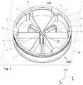
- the figure 1 shows an isometric view of a pivotal mechanism 100 (also called a "pivot" thereafter) with radial symmetry and the figure 2 shows a top view of the pivot 100, according to one embodiment.
- the pivot 100 comprises a movable part 2 (taking the form of a mobile ring in the figure 1 ) connected to a fixed part 1 (also taking the form of a ring) via a number N of flexible (or hinged) connections 9.
- the fixed ring 1 is intended to be attached to a fixed base (not shown).
- the fixed base can be located outside or inside the fixed ring 1.
- N is 3 in the example chosen.
- each of the flexible links 9 comprises a first flexible main blade 6 and a second flexible main blade 7, each of the main blades 6, 7 extending radially from the pivot axis 101 of the pivot 100.
- the main blades 6, 7 are spaced angularly relative to each other by 60 °, according to the example chosen, but could be spaced from another angle, for example an angle of 360 / (2 * N) degrees.
- first main blade 6 is connected to the mobile ring 2 and the other end is connected to an intermediate junction 8.
- One end of the second main blade 7 is connected to the fixed ring 1 and the other end is connected to the intermediate junction 8.
- the intermediate junction 8 is disposed between the first main blade 6 and the second main blade 7, close to the pivot axis 101.
- the first main blade 6, the intermediate junction 8 and the second main blade 7 are arranged kinematically in series.
- the configuration of the pivot 100 of the figure 1 having three pairs of main blades 6, 7 thus comprises three intermediate junctions 8.
- the pivot 100 will comprise N intermediate junctions 8.
- the flexible elements 9 are configured to guide a rotational movement about the pivot axis 101 of the pivot 100, the movable ring 2 in a plane P substantially perpendicular to the axis 101.
- the plane P is represented by the x, y Cartesian coordinates and the pivot axis 101 extends along z.
- the flexible links 9 exert a restoring force on the movable ring 2 so that, when the mobile ring 2 is pivoted at a given angle from a rest position, the latter pivots in oscillation around the pivot axis 101 with a first angular amplitude (or angular stroke) ⁇ 1 which depends on the flexible connections 9.
- Each of the intermediate seams 8 comprises an expansion slot 25.
- the expansion slot 25 can expand to allow a second angular amplitude ⁇ 2 greater than the first angular amplitude ⁇ 1 .
- the figure 10 illustrates a pivot 100 in a rotated position about the axis 101, showing the first and second main blades 6, 7 bent and the expansion slot 25 of the intermediate junctions 8 in open configuration.
- first main blade 6 and the second main blade 7 extend between the pivot axis 101 and the rings 1, 2 in the plane P.
- One end of the first main blade 6 is fixed on the mobile ring 2 via a first (preferably rigid) connection 4 offset, without contact with the fixed ring 1 and secured to the mobile ring 2, by
- the second main blade 7 is fixed on the fixed ring 1 by means of a second fixed link 5.
- the intermediate junctions 8 are interconnected, two by two, by a coupling element 14.
- the coupling element 14 comprises two flexible coupling blades 12, 13 arranged in parallel and fixed at one of their ends to a rigid long frame 11 integral with the intermediate junction 8, and at the other proximal end of the pivot axis 101, to a short rigid frame 10, also integral with the intermediate junction 8.
- the coupling element 14 forms a translation table 141 with parallel blades (see figure 13 ).
- the expansion slot 25 is preferably made between the long rigid frame 11 and the rigid short frame 10.
- each of the coupling elements 14 is configured to prevent movement out of the plane P of the movable ring 2 and to obtain lateral rigidity, which is that is to say prevent lateral movement of the movable ring 2 in the plane P (in other words, in x, y).
- the coupling elements 14 have the function of allowing the expansion slots 25 of the intermediate junction 8 to expand simultaneously, while blocking the buckling movement (torsion movement or out-of-plane movement P) of the intermediate junctions 8 as well as their non-simultaneous expansion, ie their equidistance with the pivot axis 101 of the pivot 100 (lateral rigidity).
- the scheme of the figure 3 shows a linearized view of the kinematic links of the pivot 100 of the figure 1 .
- the fixed ring (input) 1 and the movable ring (output) 2 are represented by the rectangles at both ends
- the intermediate junctions 8 are represented by the rectangles between the "large springs” representing, of a side, the main blades 7 and, on the other side, the main blades 6.
- the coupling blades 12 and 13 are represented by the "small springs”.
- the moving character of the movable ring 2 is illustrated by the arrow.
- the figure 4a shows an equivalent representation of the kinematics of the pivot mechanism 100 of the figure 1 .
- Each of the main blades 6, 7 are modeled by two fictitious pivot points (represented by the circles) in the plane P. Rigid segments are symbolized by solid lines.
- the fixed ring 1 by the anchor symbols.
- the diagram of the figure 4a is rearranged into that of the figure 4b .
- the figure 4b shows that the main blades 6, 7 and the intermediate junctions 8 form two kinematic loops (represented by the arrows).
- the number of dummy pivots is 12 (four notional pivots for the flexible links each comprising a first and second main blade 6, 7 and an intermediate junction 8).
- the figure 4c shows an equivalent representation of the kinematics of the pivot mechanism 100 of the figure 1 including the coupling blades 12, 13, modeled by two imaginary pivot points and including the movable ring 2, represented by the circle.
- Each of the coupling elements 14 has a degree of freedom in translation but fixes the other movements, in particular the orientation of the segments adjacent to the coupling element 14.
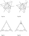
- Figures 5a and 5b represent a schema to distinguish the over-stress from the pivot mechanism of the figure 1 .
- Figures 5a and 5b distinguish the internal and external degrees of freedom of the pivot 100 with the coupling elements 14.
- the entire structure of the pivot 100 is free to move, the unconstrained entities are represented in phantom lines.
- Each of the 120 ° angles represents a topological angle of the kinematic loop. On the figure 1 each of these angles may represent the angle between the short rigid frame 10 and the long rigid frame 11 of two adjacent coupling elements 14.
- the angle in bold represents an over-stressing structure of the pivot 100.
- a single position constraint added to the output 2 of the mechanism (for example a displacement of 15 ° of the output 2) makes it possible to block the entire structure.
- the constrained (fixed) entities are in solid black line.
- Constrained entities are represented in solid lines.
- the Figures 5c and 5d schematically represent the over-stress generated by the connection of the three coupling elements 14.
- the points A, B and C represent points connected by the coupling elements 14.
- the segment AB is fixed, the points A and B are defined.
- the segment BC is arranged with a length / variable and an orientation imposed by the constraint C2.
- the orientations of each of the segments of the triangle are defined.
- the structure however has an over stress C3.
- the pivot 100 according to the invention is compact and consists solely of quasi-two-dimensional elements.
- the geometric center of the pivot 100 (corresponding to the pivot axis 101) does not move during the deflection of the blades 6, 7, 12, 13 and the vibration modes have no effect on the position of the geometric center of the pivot 100.
- no internal mode is excited by an external translational disturbance.
- a very large angular stroke can be reached. This stroke depends directly on the number of flexible links 9. Indeed, the higher the number, the more mobile elements will interfere with each other quickly during rotation.
- the coupling elements 14 significantly increase the transverse stiffness of the pivot 100 and constitute one of the major improvements of this pivot relative to those of the state of the art.
- several similar pivots can easily be stacked without losing the performance characteristics.
- the material constituting the parts of the pivot 100 is preferably a metal, but it may also include quartz, a glass, a metal glass, silicon or a polymer.
- the pivot 100 described here has many advantages.
- the pivot 100 makes it possible in particular to obtain a high angular stroke, for example a second angular amplitude ⁇ 2 around 45 ° with respect to a first angular amplitude ⁇ 1 which would typically be about 10 ° to 15 ° in the case where the intermediate junctions 8 do not include an expansion slot 25.
- the pivot 100 of the invention makes it possible to obtain an amplitude increase (difference between the second angular amplitude ⁇ 2 and the first angular amplitude ⁇ 1 ) between twice and four times the first angular amplitude ⁇ 1 maximum, or typically between two times and three times the first angular amplitude ⁇ 1 .
- a stiffness ratio of 30,000 can be obtained for Kr / KRz.
- KRz as a linear stiffness with radius, the external dimension of the pivot 100.
- the ratio Kr / KRz corresponds to the quotient of the radial stiffness by the natural angular stiffness related to the outer diameter of the ring 1, 2, where the stiffness natural angular corresponds to the stiffness of rotation of the pivot 100 about the pivot axis 101.
- a stiffness ratio higher than 10,000 is admitted as a characteristic value of a good flexible guide.
- the lateral stiffnesses of the pivot 100 are homogeneous, that is to say, substantially the same, regardless of the radial direction.
- the position of geometric center of the pivot100 (corresponding to the pivot axis 101) does not vary during the rotation in the lateral directions (lateral rigidity, preventing movement in the plane P) and varies extremely little in the axial direction (this is that is, in the direction of the axis 101).
- the pivot 100 does not have internal degrees of freedom.
- the pivot 100 has only few over-stresses. It is possible, depending on the method of construction of the pivot 100, to have no over-stress in the plane P.
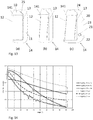
- each of the main blades 6, 7 and / or coupling blades 12, 13, 16 are of the straight type ( figure 6a ).
- Each of the main blades 6, 7 and / or coupling blades 12, 13, 16 may comprise a stiffening portion 17 in their middle ( figure 6b ).
- Each of the main blades 6, 7, and / or coupling blades 12, 13, 16 may also comprise a non-straight profile 18, for example being refined at their point of inflection 18 ( Figure 6c ).
- Each of the main blades 6, 7 and / or coupling blades 12, 13, 16 may be straight in thickness, but have a variation in stiffness by a non-constant width ( figure 6d ).
- the non-constant width can also be obtained by an opening 19 made in the blade ( figure 6e ).
- the opening may be circular, oval or rectangular along the longitudinal section of the blade.
- each of the main blades 6, 7 and / or coupling blades 12, 13, 16 may have a profile defined by a polynomial function.
- first and second main blades 6, 7 may be arranged non-radially about the pivot axis 101 but rather be laterally offset, i.e., with respect to the radial direction.
- first and second main blades 6, 7 may be offset laterally in pairs, so that each of the two blades 6, 7 intersect at a point which is offset from the geometric center of the pivot 100.
- Crossing is understood to mean blades 6, 7 a virtual point of intersection, because there is no physically crossing blades.
- the main blades 6, 7 may be inclined relative to their radial orientation in the plane P (these blades are said to be tangential and may not all meet in the center (on pivot axis 101) . These variants make it possible to increase still the compactness of the pivot 100.
- the coupling elements 14 may take different forms. It can be either flexible elements or slippery elements or rolling elements.
- each of the coupling elements 14 forms a slideway represented by the sliding element 80, integral with the intermediate junction 8 and able to move (slide) laterally along the coupling element 14 when the pivot mechanism 100 is deflected.
- the slide-forming coupling elements 14 allow the intermediate junctions 8 to have a relative expansion movement with respect to each other, during the deflection of the pivoting mechanism 100, while allowing a common movement of the intermediate junctions 8 in rotation around of the pivot axis 100.
- the slide-forming coupling elements 14 can be made by flexible elements (such as flexible blades).
- flexible elements such as flexible blades
- two parallel flexible blades can be arranged to make a slide, such as a rail or a linear table, moving only in translation.
- a single blade can also be used to provide translation guidance.
- Any other set of flexible elements allowing a total or partial guidance of the intermediate junctions 8 with respect to each other can also be used.
- the figure 8 shows an isometric view ( figure 8a ) and a view from below ( figure 8b ) of the pivot 100 according to another embodiment.
- one of the three coupling elements 14 has only one coupling blade 16. This arrangement makes it possible to eliminate the single planar over-stress present in the configuration of the pivot 100 of the figure 1 .
- the central kinematic loop is constituted by a series of three coupling elements 14 each comprising two parallel coupling blades 12, 13, each of the blades 12, 13 imposing the orientation in the plane P of an intermediate junction 8 with respect to to another.
- the coupling elements 14 and the intermediate junctions 8 see FIG. figure 4a
- the orientation of the starting portion is imposed twice. This is where the over-constraint appears.
- this over-stress has no adverse effect.
- the figure 9 shows an isometric view ( figure 9a ) and a view from above ( figure 9b ) of a pivot assembly 200 according to one embodiment.
- the pivot assembly 200 comprises two pivot mechanisms 100a and 100b mounted superimposed concentrically on the same pivot axis 101.
- the moving part (here, the movable ring) 2a of the upper pivot 100a (upper stage) and the fixed part (here, the fixed ring) 1b of the lower pivot 100b (lower stage) respectively represent the output and the inlet of the pivot assembly 200.
- the movable ring of the lower pivot 100b which corresponds to the mobile ring 2 of the pivot 100 of the figure 1 , is replaced in the pivot assembly 200 by an inter-stage coupling part 15, kinematically connected to the fixed ring 1b through the main blades 6, 7 of the lower pivot 100b and rigidly connected to the movable ring 2a of the upper pivot 100a.
- the first main blade 6 of the lower pivot 100b is connected to the fixed ring 1b by a first lower link 4b.
- the second main blade 7 of the lower pivot 100b is connected to the inter-stage coupling part 15 by a second lower link 4b.
- the first main blade 6 of the upper pivot 100a is connected to the interstage coupling part 15 by a first upper link 4b and the second main blade 7 of the upper pivot 100a is connected to the mobile ring 2a of the upper pivot 100a by a first upper link 4a.
- the fixed ring 1b can be fixed to a fixed base.
- the interstage coupling piece 15 pivots by deflection of the main blades 6, 7 (and coupling blades 12, 13) of the lower pivot 100b and the movable ring 2a of the upper pivot 100a deflection of the main blades 6, 7 (and coupling blades 12, 13) of the upper pivot 100a.
- the figure 10 shows the pivot assembly 200 in a position angularly rotated about the axis 101. It shows the main blades 6, 7 and the coupling blades 12, 13 deflected.
- the angular travel of the pivot assembly 200 is substantially twice that of the simple pivot 100
- the expansion slot 25 allowing greater radial expansion of the intermediate junctions 8 and increasing the angular stroke of each of the pivots 100a, 100b, 100c.
- the pivot assembly 200 comprising two pivots 100 makes it possible to obtain a high angular stroke, for example around 90 °.
- the figure 11 represents a block diagram of the pivot assembly 200 according to the variant of the figure 9 . It contains, for each of the pivots 100a, 100b, the main blades 6, 7, the coupling blades 12, 13, the intermediate junctions 8, and the input (the fixed ring) 1b and the output (l mobile ring) 2a.
- the pivot assembly 200 includes an internal degree of freedom corresponding to the inter-stage coupling part 15 which is free to rotate freely around the axis 101.
- the moving parts of the pivot assembly 200 (that is that is, the movable ring 2a of the upper pivot 100a and the interstage coupling part 15) being axisymmetric (the center of mass of these two parts are centered on the axis 101), the rotation of these moving parts will not be affected by shocks or vibration in translation of the pivot assembly 200.
- the rotational vibration mode of the inter-stage coupling part 15 can not be excited by a translation disturbance exerted on the assembly pivot 200, the center of mass 101 of the pivot assembly 200 pivots only on the axis 101.
- the pivot assembly 200 may comprise more than two pivots 100, for example three, or even M pivots 100.
- the pivots 100 of the pivot assembly 200 may be stacked either by axial offset of one of the pivots with respect to Other pivots 100.
- the pivots 100 of the pivot assembly 200 may also be stacked by chirality, i.e. two adjacent pivots in a stack of pivots 100 are arranged to be mirror image one. on the other in the plane P.
- Pivots as described may be stacked to provide a pivot with a stroke increased by a factor equivalent to the number of stages.
- the pivot assembly 200 is compact and consists only of quasi two-dimensional elements. In other words, each of the pivots 100, 100a, 100b can be manufactured by two-dimensional machining techniques.
- the pivot assembly 200 comprises three pivot mechanisms superimposed concentrically on the same pivot axis 101.
- the pivot assembly 200 includes an intermediate pivot 100c disposed between an upper pivot 100a and a lower pivot 100b.
- the intermediate pivot 100c may have a thickness greater than that of the upper pivots 100a and lower 100b.
- the thickness of each of the upper pivots 100a and lower 100b may be two half that of the intermediate pivot 100c.
- Such a pivot assembly may comprise an inter-stage coupling part 15 between the lower pivot 100b and the intermediate pivot 100c and between the intermediate pivot 100c and the upper pivot 100a.
- the two inter-stage coupling parts 15 can be secured.
- the pivot assembly 200 functions as if it included two pivots 100.
- the output 2 (or outputs) intermediate (s) between each pivot 100 is an internal degree of freedom.
- an auxiliary mechanism enabling the internal degrees of freedom to be enslaved to the external movement of the output of the pivot 100.
- a pivot assembly 200 comprising several pivots 100 (stages) stacked, it is possible to angularly offset the output of the lower pivot 100b with respect to the input of the upper pivot 100a. That is, to create a static precharge and move the equilibrium point of the interstage coupling part.
- the angular position of the first main blade 6 of the lower pivot 100b is not coplanar with the first main blade 6 of the upper pivot 100a.
- pre-deflect the coupling blades 12, 13 it is possible to pre-deflect the coupling blades 12, 13 in order to reduce the angular travel of the coupling element 14 (for example by half).
- the figure 13 illustrates the coupling element 14 comprising two parallel coupling blades 12, 13, according to three variants.
- the coupling blades 12, 13 are machined essentially straight and non-preloaded.
- the coupling blades 12, 13 are machined deformed and non-preloaded, or machined straight and then preloaded.
- the stiffness performance is improved for high deflection angles of the blades 12, 13 and the effects of parasitic movements of the coupling elements 14 (quadratic effect) are reduced.
- the effects are the same as in the variant of the figure 13b but, in addition, the mechanical stress in the coupling blades 12, 13 is decreased.
- the figure 13c illustrates a particular embodiment in which the long rigid frame 11 of the coupling element 14 comprises a slot 20 and a pin 22 in a housing 21.
- This arrangement makes it possible to machine the coupling blades 12, 13 straight in the frame long rigid 11 when the slot 20 is widened, that is to say when a first portion 23 of the long rigid frame 11, on which one end of the blades 12, 13 is fixed, is remote from a second portion 24 of the long rigid frame 11.
- the slot 20 is closed by bringing the first portion 23 of the second portion 24, by bending the coupling blades 12, 13.
- the first portion 23 can be secured to the second portion 24 by clipping, gluing or any other suitable means.
- the figure 14 compares the transverse stiffness performance of the pivot 100 of the invention with that of a pivot typical of the flexible mechanisms, more particularly of a flexible pivot called “butterfly” as described in the document " S. Henein, P. Spanoudakis, S. Droz, LI Myklebust, and E. Onillon, "Flexure pivot for aerospace mechanisms,” in 10th European Space Mechanisms and Tribology Symposium, San Diego, Spain, 2003, pp. 285-288 We see that we gain half a scale of the three quantities compared at the end of the race.It should be noted that the comparison is made on a similar dimensional basis.
- the fixed part 1 and the moving part 2 can take a shape other than that of a ring.
- the fixed part 1 and / or the moving part 2 can take a triangular, quadrilateral, polygonal, elliptical or any other shape.
- the fixed part 1 and the moving part 2 are arranged so that the center of inertia of the fixed part 1 and mobile 2 coincides with the axis 101 of pivoting of the pivot.
- This pivot can be used for applications in the field of precision instrumentation, space in particular, but also in the fields of robotics, industrial mechanisms of high precision, vacuum technology or in the watch industry.
Landscapes
- Engineering & Computer Science (AREA)
- General Engineering & Computer Science (AREA)
- Remote Sensing (AREA)
- Aviation & Aerospace Engineering (AREA)
- Mechanical Engineering (AREA)
- Physics & Mathematics (AREA)
- General Physics & Mathematics (AREA)
- Manufacturing & Machinery (AREA)
- Pivots And Pivotal Connections (AREA)
- Transmission Devices (AREA)
Abstract
Description
- La présente invention concerne un mécanisme pivot pour le guidage de précision en rotation et permettant de parcourir une plage angulaire importante. La présente invention concerne également un ensemble pivot comprenant un pluralité de mécanismes pivots.
- Le document
EP0974761 décrit un pivot à éléments flexibles permettant une course angulaire inférieure à l'invention proposée. Ce pivot offre des raideurs élevées, mais présente de nombreuses sur-contraintes. Il offre un dégagement autour de son axe central, ce qui est un avantage. Il propose en outre des couplages au niveau des étages intermédiaires, mais ceux-ci n'offrent pas les mêmes avantages que ceux de la présente invention: isostatisme, faible non-linéarité de raideur, grande course. Il est possible de l'empiler de même que la présente invention. -
EP2256039 décrit un pivot à lames radiales qui propose une course nettement inférieure à celle de l'invention proposée. Il offre également un dégagement autour de son axe central et propose des couplages rigides au niveau des étages intermédiaires, ce qui est très défavorable à une course élevée. Des variantes proposent des empilements d'étages successifs ou encore une disposition en « sandwich », c'est-à-dire où le deuxième étage est réparti en deux moitiés égales disposées à l'extérieur du premier étage. Ceci évite un mouvement de torsion des portions intermédiaires ainsi qu'un déplacement axial de la sortie du pivot. Ce pivot propose une disposition des lames avec l'entrée et la sortie du mécanisme à l'intérieur alors que l'étage intermédiaire est disposé à l'extérieur. -
WO2017077469 décrit un pivot permettant de couvrir une large plage angulaire. Le mouvement parasite de raccourcissement apparent des lames est déporté à l'extérieur du pivot, au niveau des encastrements des lames radiales, ce qui provoque une dérigidification de l'ensemble du pivot. Le pivot possède des liaisons intermédiaires non-couplées, qui premièrement constituent des degrés de liberté internes, ce qui est très défavorable pour la tenue aux vibrations et deuxièmement, du fait de l'absence de couplage entre les liaisons intermédiaires, les raideurs latérales en seront fortement prétéritées, particulièrement dans une position fléchie du pivot. - Les pivots flexibles présentés dans l'état de l'art sont généralement constitués de pivots simples, qui sont empilés de manière sérielle lorsque l'on désire augmenter la course angulaire.
- L'invention décrite ici propose un mécanisme pivot pour le guidage en rotation, comprenant une pièce mobile relié à une pièce fixe par l'intermédiaire de liaisons flexibles; les éléments flexibles étant configurés de manière à guider la pièce mobile selon un mouvement en rotation dans un plan, autour d'un axe de pivotement du pivot, perpendiculaire au plan; chacune des liaisons flexibles comprenant une jonction intermédiaire, chaque jonction intermédiaire étant séparée des jonctions intermédiaires adjacentes par une fente d'expansion, la fente d'expansion étant configurée pour s'élargir lors de la rotation de la pièce mobile, de manière à ce que ce dernier puisse pivoter selon une seconde amplitude angulaire plus grande qu'une première amplitude angulaire obtenue en absence de ladite fente d'expansion; les jonctions intermédiaires étant reliées entre elles par un élément de couplage; chacun des éléments de couplage étant configuré de manière à empêcher un mouvement hors du plan et un mouvement latéral dans le plan de la pièce mobile.
- L'invention décrite ici propose un mécanisme pivot pour le guidage en rotation présentant une cinématique parallèle. Dans le mécanisme pivot à cinématique parallèle, la sortie (la pièce mobile) est liée à une base fixe par l'intermédiaire de plusieurs chaines cinématiques indépendantes (en parallèle). Cette configuration offre des performances remarquables en termes de précision et de raideur, entre autres. On entend par performances de raideur des rapports élevés entre les raideurs des mouvements transverses bloqués et la raideur du mouvement libre du pivot autour de son axe de rotation. Si les performances de raideur peuvent être souvent accompagnées d'un degré de sur-contraintes élevé, ceci n'est pas le cas de la structure présentée, qui décrit effectivement un mécanisme quasi-isostatique.
- Le mécanisme pivot de l'invention, un éventuel mouvement parasite est absorbé à l'intérieur du pivot par les éléments de couplage, ce qui tend à rigidifier l'ensemble des mouvements bloqués du pivot.
- Dans le mécanisme pivot de l'invention, aucun degré de liberté interne n'est sensible aux vibrations ou ne crée une perte de raideur lorsque le mécanisme pivot est pivoté par rapport à une position d'équilibre et que les liaisons flexibles sont défléchies.
- D'autres avantages, buts et caractéristiques de la présente invention ressortiront de la description qui va suivre, faite, dans un but explicatif et nullement limitatif, en regard des figures annexées dans lesquelles:
- la
figure 1 montre un mécanisme pivot pour le guidage en rotation, selon un mode de réalisation; - la
figure 2 montre une vue de dessus du mécanisme pivot de lafigure 1 ; - la
figure 3 montre un schéma d'une vue linéarisée des liaisons cinématiques du mécanisme pivot de lafigure 1 ; - les
figures 4a à 4d représentent un schéma d'un équivalent cinématique du mécanisme pivot de lafigure 1 ; - les
figures 5a et 5b représentent un schéma permettant de distinguer la sur-contrainte du mécanisme pivot de lafigure 1 ; - les
figures 5c et 5d représentent schématiquement les sur-contraintes engendrée par la liaison de trois éléments de couplage du mécanisme pivot; - les
figures 6a à 6e illustrent des lames principales du mécanisme pivot, selon différentes formes d'exécution; - la
figure 7 représente schématiquement des éléments de couplages du mécanisme pivot, selon un mode de réalisation; - les
figures 8a et 8b montrent une vue isométrique (figure 8a ) et une vue de dessus (figure 8b ) du mécanisme pivot, selon un autre mode de réalisation; - les
figures 9a et 9b montrent une vue isométrique (figure 9a ) et une vue de dessous (figure 9b ) d'un ensemble pivot comprenant deux mécanismes pivot, selon un mode de réalisation; - la
figure 10 montre l'ensemble pivot dans une position pivotée angulairement; - la
figure 11 représente un schéma fonctionnel de l'ensemble pivot selon la variante de lafigure 9 ; - la
figure 12 montrent une vue isométrique de l'ensemble pivot, selon un autre mode de réalisation; - les
figures 13a à 13c représentent un élément de couplage du mécanisme pivot, selon différentes formes d'exécution; et - la
figure 14 compare les performances des raideurs transverses du mécanisme pivot de l'invention avec celle d'un pivot typique des mécanismes flexibles. - La
figure 1 montre une vue isométrique d'un mécanisme pivot 100 (également appelé "pivot" par la suite) à symétrie radiale et lafigure 2 montre une vue de dessus du pivot 100, selon un mode de réalisation. En particulier, le pivot 100 comprend une pièce mobile 2 (prenant la forme d'un anneau mobile dans lafigure 1 ) relié à une pièce fixe 1 (prenant également la forme d'un anneau) par l'intermédiaire d'un nombre N de liaisons flexibles (ou articulées) 9. L'anneau fixe 1 est destiné à être attaché à une base fixe (non représentée). La base fixe peut se situer à l'extérieur ou à l'intérieur de l'anneau fixe 1. N vaut 3 dans l'exemple choisi. Dans le mode de réalisation de lafigure 1 , chacune des liaisons flexibles 9 comprend une première lame principale flexible 6 et une seconde lame principale flexible 7, chacune des lames principales 6, 7 s'étendant radialement à partir de l'axe de pivotement 101 du pivot 100. Les lames principales 6, 7 sont espacées angulairement l'une par rapport à l'autre de 60°, selon l'exemple choisi, mais pourraient être espacées d'un autre angle, par exemple d'un angle valant 360/(2*N) degrés. - Une extrémité de la première lame principale 6 est reliée à l'anneau mobile 2 et l'autre extrémité est reliée à une jonction intermédiaire 8. Une extrémité de la seconde lame principale 7 est reliée à l'anneau fixe 1 et l'autre extrémité est reliée à la jonction intermédiaire 8. La jonction intermédiaire 8 est disposée entre la première lame principale 6 et la seconde lame principale 7, à proximité de l'axe de pivotement 101. La première lame principale 6, la jonction intermédiaire 8 et la seconde lame principale 7 sont donc arrangées cinématiquement en série. La configuration du pivot 100 de la
figure 1 comportant trois paires de lames principales 6, 7 comprend donc trois jonctions intermédiaires 8. Dans une configuration du pivot 100 comprenant N de liaisons flexibles 9, le pivot 100 comprendra N jonctions intermédiaires 8. - Les éléments flexibles 9 sont configurés de manière à guider un mouvement en rotation, autour de l'axe de pivotement 101 du pivot 100, de l'anneau mobile 2 dans un plan P essentiellement perpendiculaire à l'axe 101. Dans la
figure 1 , le plan P est représenté par les coordonnées cartésiennes x, y et l'axe de pivotement 101 s'étend selon z. En particulier, les liaisons flexibles 9 exercent une force de rappel sur l'anneau mobile 2 de sorte que, lorsque l'anneau mobile 2 est pivoté selon un angle donné à partir d'une position de repos, ce dernier pivote en oscillation autour de l'axe de pivotement 101 avec une première amplitude angulaire (ou course angulaire) θ1 qui dépend des liaisons flexibles 9. Chacune des jonctions intermédiaires 8 comprend une fente d'expansion 25. Lors de la rotation de l'anneau mobile 2, la fente d'expansion 25 peut s'élargir de manière à permettre une seconde amplitude angulaire θ2 plus grande que la première amplitude angulaire θ1. Lafigure 10 illustre un pivot 100 dans une position pivotée autour de l'axe 101, montrant les premières et secondes lames principales 6, 7 fléchies et la fente d'expansion 25 des jonctions intermédiaires 8 en configuration ouverte. - Dans la forme d'exécution du pivot 100 illustré à la
figure 1 , la première lame principale 6 et la seconde lame principale 7 s'étendent entre l'axe de pivotement 101 et les anneaux 1, 2 dans le plan P. Une extrémité de la première lame principale 6 est fixée sur l'anneau mobile 2 par l'intermédiaire d'une première liaison (préférablement rigide) 4 déportée, sans contact avec l'anneau fixe 1 et solidaire de l'anneau mobile 2, par exemple par le biais d'une jonction rigide 3. La seconde lame principale 7 est fixée sur l'anneau fixe 1 par le biais d'une seconde liaison fixe 5. - Dans un mode de réalisation préféré, les jonctions intermédiaires 8 sont reliées entre elles, deux par deux, par un élément de couplage 14.
- Dans l'exemple illustré à la
figure 1 , l'élément de couplage 14 comprend deux lames flexibles de couplage 12, 13 arrangées de manière parallèle et fixées à l'une de leur extrémités à un cadre rigide long 11 solidaire de la jonction intermédiaire 8, et à l'autre extrémité proximale de l'axe de pivotement 101, à un cadre rigide court 10, également solidaire de la jonction intermédiaire 8. Dans cette configuration, l'élément de couplage 14 forme une table de translation 141 à lames parallèles (voirfigure 13 ). La fente d'expansion 25 est préférablement pratiquée entre le cadre rigide long 11 et le cadre rigide court 10. - Dans une configuration où les jonctions intermédiaire 8 comprennent une fente d'expansion 25, chacun des éléments de couplage 14 est configuré de manière à empêcher un mouvement hors du plan P de l'anneau mobile 2 et à obtenir une rigidité latérale, c'est-à-dire empêcher un mouvement latéral de l'anneau mobile 2 dans le plan P (autrement dit, en x, y).
- Plus particulièrement, les éléments de couplage 14 ont pour fonction de permettre l'expansion simultanée des fentes d'expansion 25 des jonction intermédiaire 8, tout en bloquant le mouvement de gauchissement (mouvement de torsion ou mouvement hors du plan P) des jonction intermédiaire 8 ainsi que leurs expansion non-simultanée, soit leur équidistance avec l'axe de pivotement 101 du pivot 100 (rigidité latérale).
- Le schéma de la
figure 3 montre une vue linéarisée des liaisons cinématiques du pivot 100 de lafigure 1 . Dans le schéma, l'anneau fixe (entrée) 1 et l'anneau mobile (sortie) 2 sont représentés par les rectangles aux deux extrémités, les jonctions intermédiaires 8 sont représentées par les rectangles entre les "grands ressorts" représentant, d'un côté, les lames principales 7 et, de l'autre côté, les lames principales 6. Les lames de couplage 12 et 13 sont représentées par les "petits ressorts". Le caractère mobile de l'anneau mobile 2 est illustré par la flèche. - La
figure 4a montre une représentation équivalente de la cinématique du mécanisme pivot 100 de lafigure 1 . Chacune des lames principales 6, 7 sont modélisées par deux points pivots fictifs (représentés par les cercles) dans le plan P. Les segments rigides sont symbolisés par des lignes continues. L'anneau fixe 1 par les symboles d'ancrage. - Afin de mettre en évidence le nombre de boucles cinématiques, le schéma de la
figure 4a est réarrangé en celui de lafigure 4b . Lafigure 4b montre que les lames principales 6, 7 et les jonctions intermédiaires 8 forment deux boucles cinématiques (représentées par les flèches). De plus, le nombre de pivots fictifs est de 12 (quatre pivots fictifs pour les liaisons flexibles comprenant chacune une première et seconde lame principale 6, 7 et une jonction intermédiaire 8). - La
figure 4c montre une représentation équivalente de la cinématique du mécanisme pivot 100 de lafigure 1 incluant les lames de couplage 12, 13, modélisées par deux points pivots fictifs et incluant l'anneau mobile 2, représenté par le cercle. Lafigure 4d réarrangée montre que le système comprend huit boucles b cinématiques (b = 8). De plus, le nombre de pivots fictifs p correspond à 24 (p = 24). - Chacun des éléments de couplage 14 possède un degré de liberté en translation mais fixe les autres mouvements, notamment l'orientation des segments adjacents à l'élément de couplage 14. Les
figures 5a et 5b représentent un schéma permettant de distinguer la sur-contrainte du mécanisme pivot de lafigure 1 . En particulier, lesfigures 5a et 5b permettent de distinguer les degrés de liberté internes et externes du pivot 100 avec les éléments de couplage 14. Dans lafigure 5a , toute la structure du pivot 100 est libre de se déplacer, les entités non contraintes sont représentées en traits tillés. Chacun des angles de 120° représente un angle topologique de la boucle cinématique. Sur lafigure 1 , chacun de ces angles peuvent représenter l'angle entre le cadre rigide court 10 et le cadre rigide long 11 de deux éléments de couplage 14 adjacents. L'angle en gras représente une sur-contrainte la structure du pivot 100. Dans lafigure 5b , une seule contrainte de position ajoutée sur la sortie 2 du mécanisme (par exemple un déplacement de 15° de la sortie 2) permet de bloquer l'ensemble de la structure. Les entités contraintes (fixées) sont en trait noir plein. Les entités contraintes sont représentées en traits pleins. - Les
figures 5c et 5d représentent schématiquement la sur-contrainte engendrée par la liaison des trois éléments de couplage 14. Les points A, B et C représentent des points reliés par les éléments de couplage 14. Lorsque l'on fixe le segment AB, les points A et B sont définis. Puis à partir du point A, on fixe le segment AC avec une longueur / libre et une orientation donnée, imposée par la contrainte angulaire C1. De même, le segment BC est disposé avec une longueur / variable et une orientation imposée par la contrainte C2. Ainsi les orientations de chacun des segments du triangle sont définies. Lorsque l'on rajoute la contrainte C3, qui définit l'orientation entre les segments AC et BC, on ajoute une sur-contrainte, car celle-ci est déjà donnée indirectement par les contraintes C1 et C2, ainsi que la topologie des liaisons. - Les
figures 5a à 5d montrent que le mécanisme pivot 100 est isostatique extérieurement. C'est-à-dire que le système est libre de se déplacer avec un degré de liberté en rotation (figure 5a ) et l'ajout d'une seule contrainte de position angulaire bloque l'ensemble du mécanisme (figure 5b ). Il n'y a donc pas de degré de liberté interne (DDL int = 0) et il y a un seul degré de liberté externe (DDL ext = 1). - La structure présente toutefois une sur-contrainte C3. La boucle centrale est définie par un nombre surnuméraire de contraintes angulaires. Nous avons donc H = 1.
- La vérification des grandeurs trouvées précédemment se fait par l'égalité suivante, dérivée de la formule de Grübler:


- Cette analyse confirme la présence d'une sur-contrainte et l'absence de degré de liberté interne. Par degrés de liberté interne, on entend des modes de déplacement entièrement libre d'une partie du mécanisme pivot 100. Cependant, il y a d'autres modes de déplacement qui ne sont pas caractérisés par cette analyse. Il s'agit par exemple des modes de vibration aux fréquences propres du mécanisme pivot 100. Ces modes de vibration correspondent à des modes propres de vibrations des lames 6, 7, 12, 13 ainsi que du mode en rotation du pivot 100 autour de l'axe 101, comprenant les jonctions intermédiaires 8 et les éléments de couplage 14. Toutefois ces modes de déplacement ne peuvent pas être assimilés véritablement à des degrés de liberté et présentent des raideurs hautement non-linéaires. Ils ne mènent donc pas à des déplacements élevés. Concernant les modes propres de vibration des lames 6, 7, 12, 13, ils interviennent à des fréquences très élevées et ne sont donc pas gênants. Concernant le mode propre de rotation du mécanisme pivot 100 autour de l'axe 101, comprenant les jonctions intermédiaires 8 et les éléments de couplage 14, son déplacement angulaire n'influence pas la position de centrage du pivot 100. Ainsi, nous pouvons être assurés de qualité de guidage en rotation du pivot 100.
- Le pivot 100 selon l'invention est compact et constitué uniquement par des éléments quasi bidimensionnels. De plus, le centre géométrique du pivot 100 (correspondant à l'axe de pivotement 101) ne se déplace pas lors de la déflection des lames 6, 7, 12, 13 et les modes de vibration n'ont pas d'effet sur la position du centre géométrique du pivot 100. Par ailleurs, aucun mode interne n'est excité par une perturbation externe translationnelle. Aussi, une très grande course angulaire peut être atteinte. Cette course dépend directement du nombre de liaisons flexibles 9. En effet, plus les leurs nombre est élevé, plus les éléments mobiles vont interférer les uns avec les autres rapidement lors de la rotation. Les éléments de couplage 14 (à lames parallèles) augmentent significativement les raideurs transverses du pivot 100 et constituent une des améliorations majeures de ce pivot par rapport à ceux de l'état de l'art. Finalement, afin d'augmenter la course angulaire, plusieurs pivots semblables peuvent aisément être empilés sans perdre les caractéristiques de performance.
- Le matériau constituant les pièces du pivot 100 est préférentiellement un métal, mais il peut aussi comprendre le quartz, un verre, un verre métallique, du silicium ou encore un polymère.
- Le pivot 100 décrit ici présente de nombreux avantages. Le pivot 100 permet notamment d'obtenir une course angulaire élevée, par exemple une seconde amplitude angulaire θ2 autour de 45° par rapport à une première amplitude angulaire θ1 qui serait typiquement d'environ 10° à 15° dans le cas où les jonctions intermédiaires 8 ne comprennent pas de fente d'expansion 25. Par exemple, le pivot 100 de l'invention permet d'obtenir une augmentation d'amplitude (différence entre la seconde amplitude angulaire θ2 et la première amplitude angulaire θ1) entre deux fois et quatre fois la première amplitude angulaire θ1 au maximum, ou typiquement entre deux fois et trois fois la première amplitude angulaire θ1.
- Des bonnes performances de raideurs transverses (mouvement hors du plan P de l'anneau mobile 2) sont atteintes, même pour des déflections élevées du pivot 100. Par exemple, on peut obtenir un rapport de raideur de 30'000 pour Kr / KRz, en considérant KRz comme une raideur linéaire avec pour rayon, la dimension externe du pivot 100. Le rapport Kr / KRz correspond au quotient de la raideur radiale par la raideur angulaire naturelle rapportée au diamètre externe de l'anneau 1, 2, où la raideur angulaire naturelle correspond à la raideur de rotation du pivot 100 autour de l'axe de pivotement 101. Un rapport de raideur plus élevé que 10'000 est admis comme valeur caractéristique d'un bon guidage flexible. Les raideurs latérales du pivot 100 sont homogènes, c'est-à-dire pratiquement les mêmes, quelle que soit la direction radiale.
- Selon les caractéristiques dimensionnelles du pivot 100, il est possible d'obtenir une raideur naturelle quasi-constante. La position du centre géométrique du pivot100 (correspondant à l'axe de pivotement 101) ne varie pas au cours de la rotation dans les directions latérales (rigidité latérale, empêchant un mouvement dans le plan P) et varie extrêmement peu dans la direction axiale (c'est-à-dire dans la direction de l'axe 101).
- Le pivot 100 ne présente pas de degrés de libertés internes. Le pivot 100 ne présente que peu de sur-contraintes. Il est possible, selon le mode de construction du pivot 100, de n'avoir aucune sur-contrainte dans le plan P.
- Selon une forme d'exécution illustrée dans la
figure 6 , chacune des lames principales 6, 7 et/ou lames de couplage 12, 13, 16 sont de type droites (figure 6a ). Chacune des lames principales 6, 7 et/ou lames de couplage 12, 13, 16 peut comporter une portion de rigidification 17 en leur milieu (figure 6b ). Chacune des lames principales 6, 7, et/ou lames de couplage 12, 13, 16 peut également comporter un profil non-droit 18, en étant par exemple affinées en leur point d'inflexion 18 (figure 6c ). Chacune des lames principales 6, 7 et/ou lames de couplage 12, 13, 16 peut être droite en épaisseur, mais présenter une variation de raideur par une largeur non-constante (figure 6d ). La largeur non-constante peut également être obtenue par une ouverture 19 pratiquée dans la lame (figure 6e ). L'ouverture peut être de forme circulaire, ovale ou rectangulaire le long de la section longitudinale de la lame. De manière extensive, chacune des lames principales 6, 7 et/ou lames de couplage 12, 13, 16 peut présenter un profil définit par une fonction polynômiale. - D'autres configurations (non représentées) des liaisons flexibles 9 sont également possibles. Par exemple, les première et seconde lames principales 6, 7 peuvent être arrangées de manière non radiale autour de l'axe de pivotement 101 mais plutôt être décalées latéralement, c'est-à-dire par rapport à la direction radiale. Par exemple, les première et seconde lames principales 6, 7 peuvent être décalées latéralement par paires, afin que chacune des deux lames 6, 7 se croisent en un point qui est décalé par rapport au centre géométrique du pivot 100. On entend par croisement des lames 6, 7 un point virtuel d'intersection, car il n'y a pas physiquement de croisement lames. Alternativement, les lames principales 6, 7 peuvent être inclinées par rapport à leur orientation radiale dans le plan P (ces lames sont dites tangentielles et peuvent ne pas toutes se rejoindre au centre (sur axe de pivotement 101). Ces variantes permettent d'augmenter encore la compacité du pivot 100.
- Les éléments de couplages 14 peuvent prendre différentes formes. Il peut s'agir soit d'éléments flexibles soit d'éléments glissants, soit d'éléments roulants.
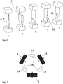
- A la
figure 7 , les trois jonctions intermédiaires 8 avec les trois éléments de couplage 14 du mécanisme pivot 100 de lafigure 1 sont représentées schématiquement, selon une forme d'exécution. En particulier, chacun des éléments de couplage 14 forme une glissière représentée par l'élément glissant 80, solidaire de la jonction intermédiaire 8 et pouvant se déplacer (glisser) latéralement le long de l'élément de couplage 14 lorsque le mécanisme pivot 100 est défléchi. Les éléments de couplages 14 formant glissière permettent aux jonctions intermédiaires 8 d'avoir un mouvement relatif d'expansion les unes par rapport aux autres, lors de la déflection du mécanisme pivot 100, tout en permettant un mouvement commun des jonctions intermédiaires 8 en rotation autour de l'axe du pivot 100. - Les éléments de couplage 14 formant glissière peuvent être réalisés par des éléments flexibles (tels que des lames flexibles). Par exemple, deux lames flexibles parallèles peuvent être arrangées de manière à réaliser une glissière, telle qu'un rail ou une table linéaire, se déplaçant seulement en translation. Une seule lame peut également être utilisée afin de réaliser un guidage en translation. Tout autre ensemble d'éléments flexibles permettant un guidage total ou partiel des jonctions intermédiaires 8 les unes par rapport aux autres peut également être utilisé.
- La
figure 8 montre une vue isométrique (figure 8a ) et une vue de dessous (figure 8b ) du pivot 100 selon un autre mode de réalisation. Dans cette variante, l'un des trois éléments de couplage 14 ne comporte qu'une seule lame de couplage 16. Cet arrangement permet de faire disparaitre l'unique sur-contrainte planaire présente dans la configuration du pivot 100 de lafigure 1 . - Un autre avantage de cette implémentation est de rendre le pivot 100 isostatique. En effet, selon le mode de réalisation des
figures 1 et2 , la boucle cinématique centrale est constituée d'une série de trois éléments de couplage 14 comprenant chacun deux lames de couplage 12, 13 parallèles, chacune des lames 12, 13 imposant l'orientation dans le plan P d'une jonction intermédiaire 8 par rapport à une autre. Ainsi, si l'on parcourt la chaine cinématique formée par les éléments de couplage 14 et les jonctions intermédiaires 8 (voir lafigure 4a ), depuis une jonction intermédiaire 8, on constate que l'orientation angulaire des segments est imposée tout au long de la chaine. Lorsque l'on a fait le tour de la boucle cinématique (voir lafigure 4b ) on s'aperçoit que l'orientation de la portion de départ est imposée deux fois. C'est ici qu'apparait la sur-contrainte. Toutefois, dans le cas d'un usinage monolithique du pivot 100, ainsi qu'en l'absence de gradient thermique au sein du pivot 100, cette sur-contrainte n'a pas d'effet néfaste. - Il va de soi que la présente invention n'est pas limitée au mode de réalisation qui vient d'être décrit et que diverses modifications et variantes simples peuvent être envisagées par l'homme de métier sans sortir du cadre de la présente invention.
- Par exemple, il est possible d'assembler plusieurs pivots 100 et de les empiler afin d'obtenir un ensemble pivot ayant une course angulaire encore plus grande.
- La
figure 9 montre une vue isométrique (figure 9a ) et une vue de dessus (figure 9b ) d'un ensemble pivot 200 selon un mode de réalisation. L'ensemble pivot 200 comporte deux mécanismes pivot 100a et 100b montés superposés de manière concentrique sur le même axe de pivotement 101. Dans cette configuration, la pièce mobile (ici, l'anneau mobile) 2a du pivot supérieur 100a (étage supérieur) et la pièce fixe (ici, l'anneau fixe) 1 b du pivot inférieur 100b (étage inférieur) représentent respectivement la sortie et l'entrée de l'ensemble pivot 200. L'anneau mobile du pivot inférieur 100b, qui correspond à l'anneau mobile 2 du pivot 100 de lafigure 1 , est remplacé dans l'ensemble pivot 200 par une pièce de couplage inter-étage 15, cinématiquement liée à l'anneau fixe 1 b par l'intermédiaire des lames principales 6, 7 du pivot inférieur 100b et liée rigidement à l'anneau mobile 2a du pivot supérieur 100a. Dans l'exemple illustré à lafigure 9 , la première lame principale 6 du pivot inférieur 100b est reliée à l'anneau fixe 1 b par une première liaison inférieure 4b. La seconde lame principale 7 du pivot inférieur 100b est reliée à la pièce de couplage inter-étage 15 par une seconde liaison inférieure 4b. La première lame principale 6 du pivot supérieur 100a est reliée à la pièce de couplage inter-étage 15 par une première liaison supérieure 4b et la seconde lame principale 7 du pivot supérieur 100a est reliée à l'anneau mobile 2a du pivot supérieur 100a par une première liaison supérieure 4a. - En fonctionnement, l'anneau fixe 1b peut être fixé à une base fixe. La pièce de couplage inter-étage 15 pivote par fléchissement des lames principales 6, 7 (et des lames de couplage 12, 13) du pivot inférieur 100b et l'anneau mobile 2a du pivot supérieur 100a fléchissement des lames principales 6, 7 (et des lames de couplage 12, 13) du pivot supérieur 100a. La
figure 10 montre l'ensemble pivot 200 dans une position pivotée angulairement autour de l'axe 101. On y voit les lames principales 6, 7 ainsi que les lames de couplage 12, 13 défléchies. Dans le cas où la course angulaire de la pièce de couplage inter-étage 15 et de l'anneau mobile du pivot supérieur 100a est sensiblement la même, la course angulaire de l'ensemble pivot 200 est sensiblement le double de celle du pivot simple 100. Sur la figure, on voit également la fente d'expansion 25 permettant une plus grande expansion radiale des jonctions intermédiaires 8 et augmentant la course angulaire de chacun des pivots 100a, 100b, 100c. L'ensemble pivot 200 comprenant deux pivots 100 permet d'obtenir une course angulaire élevée, par exemple autour de 90°. - La
figure 11 représente un schéma fonctionnel de l'ensemble pivot 200 selon la variante de lafigure 9 . On y retrouve, pour chacun des pivots 100a, 100b, les lames principales 6, 7, les lames de couplage 12, 13, les jonctions intermédiaires 8, ainsi que l'entrée (l'anneau fixe) 1 b et la sortie (l'anneau mobile) 2a. L'ensemble pivot 200 comprend un degré de liberté interne correspondant à la pièce de couplage inter-étage 15 qui est libre de pivoter sans contrainte autour de l'axe 101. Cependant, les pièces mobiles de l'ensemble pivot 200 (c'est-à-dire l'anneau mobile 2a du pivot supérieur 100a et la pièce de couplage inter-étage 15) étant axisymétriques (le centre de masse de ces deux pièces sont centrés sur l'axe 101), la rotation de ces pièces mobiles ne sera pas affectée par des chocs ou vibration en translation de l'ensemble pivot 200. Autrement dit, le mode de vibration en rotation de la pièce de couplage inter-étage 15 ne peut pas être excité par une perturbation en translation exercée sur l'ensemble pivot 200, le centre de masse sur 101 de l'ensemble pivot 200 ne pivotant que sur l'axe 101. - On comprendra que l'ensemble pivot 200 peut comporter plus de deux pivots 100, par exemple trois, ou même M pivots 100. Les pivots 100 de l'ensemble pivot 200 peuvent être empilés soit par décalage axial d'un des pivots par rapport aux autres pivots 100. Les pivots 100 de l'ensemble pivot 200 peuvent également être empilés par chiralité, c'est-à-dire que deux pivots adjacents dans un empilement de pivots 100 sont arrangés de sorte à être l'image miroir l'un de l'autre dans le plan P.
- Des pivots tels que décrit (l'ensemble pivot 200) peuvent être empilés afin d'obtenir un pivot avec une course augmentée d'un facteur équivalent au nombre d'étages. L'ensemble pivot 200 est compact et n'est constitué uniquement que par des éléments quasi bidimensionnels. Autrement dit, chacun des pivots 100, 100a, 100b peut être fabriqué par des techniques d'usinage bidimensionnelles.
- Selon une forme d'exécution représentée à la
figure 12 , l'ensemble pivot 200 comporte trois mécanismes pivot superposés de manière concentrique sur le même axe de pivotement 101. Par exemple, l'ensemble pivot 200 comporte un pivot intermédiaire 100c disposé entre un pivot supérieur 100a et un pivot inférieur 100b. Le pivot intermédiaire 100c peut avoir une épaisseur plus grande que celle des pivots supérieur 100a et inférieur 100b. Par exemple, l'épaisseur de chacun des pivots supérieur 100a et inférieur 100 b peut deux être la moitié de celle du pivot intermédiaire 100c. Un tel arrangement permet à l'ensemble pivot 200 d'être plus symétrique par rapport au plan P. De la sorte, il est possible de minimiser la torsion du pivot intermédiaire 100c. Un tel ensemble pivot peut comprendre une pièce de couplage inter-étage 15 entre le pivot inférieur 100b et le pivot intermédiaire 100c et entre le pivot intermédiaire 100c et le pivot supérieur 100a. Les deux pièces de couplage inter-étage 15 peuvent être solidarisées. Dans ce cas, l'ensemble pivot 200 fonctionne comme s'il comprenait deux pivots 100. - Dans le cas d'un ensemble pivot 200 comprenant plusieurs pivots 100 (étages) empilés, la sortie 2 (ou les sorties) intermédiaire(s) entre chaque pivot 100 constitue un degré de liberté interne. Aussi, il est possible d'ajouter un mécanisme auxiliaire permettant d'asservir le (ou les) degrés de liberté interne au mouvement externe de la sortie du pivot 100. Autrement dit, il est possible de relier l'anneau mobile 2a de la sortie à la pièce de couplage inter-étage 15 de sorte que cette dernière fasse la moitié de la course angulaire par rapport à l'anneau mobile 2a supérieur.
- Dans le cas d'un ensemble pivot 200 comprenant plusieurs pivots 100 (étages) empilés, il est possible de décaler angulairement la sortie du pivot inférieur 100b par rapport à l'entrée du pivot supérieur 100a. C'est-à-dire, de créer une précharge statique et déplacer le point d'équilibre de la pièce de couplage inter-étage. Ainsi la position angulaire de la première lame principale 6 du pivot inférieur 100b n'est pas coplanaire de la première lame principale 6 du pivot supérieur 100a.
- Encore selon une autre forme d'exécution, il est possible de pré-défléchir les lames de couplage 12, 13 afin de réduire la course angulaire de l'élément de couplage 14 (par exemple de moitié). Pour ce faire, on peut soit usiner les lames de couplage 12, 13 préalablement défléchies selon leur mode exact de déformation, ou selon un mode approximé. On peut également usiner les lames de couplage 12, 13 essentiellement droites et les défléchir par précharge et fixation lors d'une étape ultérieure à l'usinage.
- La
figure 13 illustre l'élément de couplage 14 comportant deux lames de couplage parallèles 12, 13, selon trois variantes. Dans la variante de lafigure 13a , les lames de couplage 12, 13 sont usinées essentiellement droites et non-préchargées. Dans la variante desfigures 13b et 13c , les lames de couplage 12, 13 sont usinées déformée et non-préchargées, ou encore, usinées droites puis préchargées. Dans ces deux dernières variantes, les performances de raideur sont améliorées pour des angles de déflexion élevés des lames 12, 13 et les effets des mouvements parasites des éléments de couplage 14 (effet quadratique) sont diminués. Dans la variante de lafigure 13c , les effets sont les mêmes que dans la variante de lafigure 13b mais, de plus, la contrainte mécanique dans les lames de couplage 12, 13 est diminuée. - La
figure 13c illustre un exemple de réalisation particulier dans lequel le cadre rigide long 11 de l'élément de couplage 14 comporte une fente 20 et une goupille 22 dans un logement 21. Cet arrangement permet d'usiner les lames de couplage 12, 13 droites dans le cadre rigide long 11 lorsque la fente 20 est élargie, c'est-à-dire lorsqu'une première portion 23 du cadre rigide long 11, sur laquelle une extrémité des lames 12, 13 est fixée, est éloignée d'une seconde portion 24 du cadre rigide long 11. Par la suite, la fente 20 est fermée en rapprochant la première portion 23 de la seconde portion 24, par flexion des lames de couplage 12, 13. Après la fermeture de la fente 20, la première portion 23 peut être solidarisée à la seconde portion 24 par clipsage, collage ou tout autre moyen adéquat. - La
figure 14 compare les performances de raideurs transverses du pivot 100 de l'invention avec celle d'un pivot typique des mécanismes flexibles, plus particulièrement d'un pivot flexible dit "papillon" tel que décrit dans le document "S. Henein, P. Spanoudakis, S. Droz, L. I. Myklebust, and E. Onillon, "Flexure pivot for aerospace mechanisms," in 10th European Space Mechanisms and Tribology Symposium, San Sebastian, Spain, 2003, pp. 285-288". On voit que l'on gagne un demi ordre de grandeur sur les trois grandeurs comparées en fin de course. Notons que la comparaison se fait sur une base dimensionnelle semblable. - On comprendra qu'au moins l'une de la pièce fixe 1 et la pièce mobile 2 peut prendre une forme autre que celle d'un anneau. Par exemple, la pièce fixe 1 et/ou la pièce mobile 2 peut prendre une forme triangulaire, quadrilatérale, polygonale, elliptique, ou toute autre forme. Préférablement la pièce fixe 1 et la pièce mobile 2 sont arrangées de sorte que le centre d'inertie de la pièce fixe 1 et mobile 2 coïncide avec l'axe 101 de pivotement du pivot.
- Ce pivot peut être utilisé pour des applications dans le domaine de l'instrumentation de précision, spatiale en particulier, mais aussi dans les domaines de la robotique, des mécanismes industriels de haute précision, en technologie du vide ou encore dans l'horlogerie.
-
- 1
- pièce fixe, anneau fixe
- 1b
- anneau fixe inférieur
- 2
- pièce mobile, anneau mobile
- 2a
- anneau mobile du pivot supérieur
- 3
- jonction rigide
- 4
- première liaison
- 4a
- première liaison supérieure
- 4b
- première liaison inférieure
- 5
- seconde liaison fixe
- 6
- première lame principale
- 7
- seconde lame principale
- 8
- jonctions intermédiaires
- 9
- élément flexible
- 10
- cadre rigide court
- 11
- cadre rigide long
- 12, 13, 16
- lame de couplage
- 14
- élément de couplage, lames parallèles
- 141
- table de translation
- 15
- pièce de couplage inter-étage
- 17
- portion de rigidification
- 18
- point d'inflexion
- 19
- ouverture
- 20
- fente
- 21
- logement
- 22
- goupille
- 23
- première portion
- 24
- seconde portion
- 25
- fente d'expansion
- 80
- élément glissant
- 100
- pivot
- 100a
- pivot supérieur
- 100b
- pivot inférieur
- 100c
- pivot intermédiaire
- 101
- axe de pivotement du pivot
- 200
- ensemble pivot
- P
- plan
- p
- pivots fictifs
- θ1
- première amplitude angulaire
- θ2
- seconde amplitude angulaire
Claims (18)
- Mécanisme pivot (100) pour le guidage en rotation, comprenant:une pièce mobile (2) relié à une pièce fixe (1) par l'intermédiaire de liaisons flexibles (9);les éléments flexibles (9) étant configurés de manière à guider la pièce mobile (2) selon un mouvement en rotation dans un plan (P), autour d'un axe de pivotement (101) perpendiculaire au un plan (P);chacune des liaisons flexibles (9) comprenant une jonction intermédiaire (8), chaque jonction intermédiaire (8) étant séparée des jonctions intermédiaires (8) adjacentes par une fente d'expansion (25), la fente d'expansion (25) étant configurée pour s'élargir lors de la rotation de la pièce mobile (2), de manière à ce que la pièce mobile (2) puisse pivoter selon une seconde amplitude angulaire (θ2) plus grande qu'une première amplitude angulaire (θ1) obtenue en absence de ladite fente d'expansion;caractérisé en ce queles jonctions intermédiaires (8) sont reliées entre elles par un élément de couplage (14);et en ce que chacun des éléments de couplage (14) est configuré de manière à empêcher un mouvement hors du plan (P) et un mouvement latéral dans le plan (P), de la pièce mobile (2).
- Le mécanisme pivot selon la revendication 1,
dans lequel chacune des liaisons flexibles (9) comprend une première lame principale (6) et une seconde lame principale (7), chacune des lames principales (6, 7) s'étendant radialement à partir de l'axe de pivotement (101);
une extrémité de la première et seconde lame principale (6, 7) étant reliée à la pièce mobile (2) et à l'anneau fixe (1), respectivement; la première et seconde lame principale (6, 7) étant reliée entre elles par le biais d'une jonction intermédiaire (8). - Le mécanisme pivot selon la revendication 1 ou 2,
dans lequel au moins l'un des éléments de couplage (14) comprend un élément flexible, un élément glissant, ou un élément roulant. - Le mécanisme pivot selon la revendication 3,
dans lequel au moins l'un des éléments de couplage (14) comprend une seule lame de couplage (16) ou au moins deux lames de couplage (12, 13) arrangées de manière parallèle. - Le mécanisme pivot selon la revendication 4,
dans lequel les extrémités de la lame de couplage (12, 13, 16) sont fixées à un cadre rigide (11, 10) solidaire de la jonction intermédiaire (8). - Le mécanisme pivot selon l'une des revendications 1 à 5,
dans lequel une extrémité de chacune des liaisons flexibles (9) est reliée à la pièce fixe (1) par une seconde liaison fixe (5) et l'autre extrémité est reliée à la pièce mobile (2) par une première liaison (4). - Le mécanisme pivot selon l'une des revendications 1 à 6,
dans lequel les lames principales (6, 7) comportent une ou plusieurs portions de rigidification (17). - Le mécanisme pivot selon l'une des revendications1 à 7,
dans lequel les lames principales (6, 7) comportent un profil non-droit (18). - Le mécanisme pivot selon l'une des revendications 1 à 8,
dans lequel chacune des lames principales (6, 7) comportent une variation de section le long de l'axe longitudinal de la lame (6, 7). - Le mécanisme pivot selon la revendication 9,
dans lequel variation de section est obtenue par une épaisseur non-constante de la lame principale (6, 7) ou par une largeur non-constante de la lame principale (6, 7). - Le mécanisme pivot selon la revendication 10,
dans lequel les lames principales (6, 7) comportent au moins une ouverture (19). - Le mécanisme pivot selon l'une des revendications 1 à 11, dans lequel les première et seconde lames principales (6, 7) sont arrangées de manière non radiale autour de l'axe de pivotement (101).
- Le mécanisme pivot selon la revendication 12,
dans lequel les première et seconde lames principales (6, 7) sont décalées latéralement, par rapport à la direction radiale. - Le mécanisme pivot selon la revendication 13,
dans lequel les première et seconde lames principales (6, 7) sont décalées latéralement par paires, de sorte que chacune des deux lames (6, 7) se croisent en un point qui est décalé par rapport au centre géométrique du pivot (100). - Le mécanisme pivot selon l'une des revendications 1 à 14,
dans lequel les lames principales (6, 7) sont inclinées par rapport à leur orientation radiale dans le plan (P). - Ensemble pivot (200) comprenant au moins deux mécanismes pivots (100a, 100b) selon l'une des revendications 1 à 14, les mécanismes pivots (100a, 100b) étant montés superposés de manière concentrique sur le même axe de pivotement (101).
- Ensemble pivot (200) selon la revendication 16,
dans lequel le pivot supérieur 100a et le pivot inférieur 100b sont assemblés avec ou sans retournement selon un axe latéral d'un des deux mécanismes pivots (100a, 100b). - Ensemble pivot (200) selon la revendication 17,
dans lequel un des deux mécanismes pivots (100a, 100b) est, ou les deux mécanismes pivots sont, soumis à une précharge lors de l'assemblage.
Priority Applications (2)
| Application Number | Priority Date | Filing Date | Title |
|---|---|---|---|
| EP17198118.6A EP3476748B1 (fr) | 2017-10-24 | 2017-10-24 | Mécanisme pivot à éléments flexibles |
| US16/166,864 US11572918B2 (en) | 2017-10-24 | 2018-10-22 | Pivot mechanism with flexible elements for large-amplitude rotation guiding and pivot assembly comprising a plurality of said pivot mechanism |
Applications Claiming Priority (1)
| Application Number | Priority Date | Filing Date | Title |
|---|---|---|---|
| EP17198118.6A EP3476748B1 (fr) | 2017-10-24 | 2017-10-24 | Mécanisme pivot à éléments flexibles |
Publications (2)
| Publication Number | Publication Date |
|---|---|
| EP3476748A1 true EP3476748A1 (fr) | 2019-05-01 |
| EP3476748B1 EP3476748B1 (fr) | 2020-07-15 |
Family
ID=60186058
Family Applications (1)
| Application Number | Title | Priority Date | Filing Date |
|---|---|---|---|
| EP17198118.6A Active EP3476748B1 (fr) | 2017-10-24 | 2017-10-24 | Mécanisme pivot à éléments flexibles |
Country Status (2)
| Country | Link |
|---|---|
| US (1) | US11572918B2 (fr) |
| EP (1) | EP3476748B1 (fr) |
Cited By (6)
| Publication number | Priority date | Publication date | Assignee | Title |
|---|---|---|---|---|
| EP3792700A1 (fr) * | 2019-09-16 | 2021-03-17 | Patek Philippe SA Genève | Oscillateur horloger a pivot flexible |
| EP3992728A1 (fr) * | 2020-10-29 | 2022-05-04 | The Swatch Group Research and Development Ltd | Guidage flexible avec table de translation pour mecanisme resonateur rotatif, notamment d'un mouvement d'horlogerie |
| EP4012506A1 (fr) * | 2020-12-14 | 2022-06-15 | The Swatch Group Research and Development Ltd | Mécanisme resonateur d'horlogerie muni d'une table de translation |
| EP4047424A1 (fr) * | 2021-02-18 | 2022-08-24 | Patek Philippe SA Genève | Composant à pivot flexible, notamment pour l' horlogerie |
| NL2029137B1 (en) * | 2021-09-06 | 2023-03-21 | Flexous Mech Ip B V | An oscillator for a mechanical watch |
| EP4276543A1 (fr) * | 2022-05-10 | 2023-11-15 | The Swatch Group Research and Development Ltd | Ensemble de guidages flexibles pour mécanisme résonateur rotatif d'horlogerie |
Families Citing this family (14)
| Publication number | Priority date | Publication date | Assignee | Title |
|---|---|---|---|---|
| US12265359B2 (en) * | 2016-07-06 | 2025-04-01 | Ecole Polytechnique Federale De Lausanne (Epfl) | General 2 degree of freedom isotropic harmonic oscillator and associated time base without escapement or with simplified escapement |
| US10914339B2 (en) * | 2018-09-25 | 2021-02-09 | Ball Aerospace & Technologies Corp. | Flexural pivot assembly with shaped blade sections |
| FR3094803B1 (fr) * | 2019-04-05 | 2021-04-23 | Lvmh Swiss Mft Sa | Oscillateur sphérique pour mécanisme horloger |
| EP3771840B1 (fr) * | 2019-08-02 | 2022-03-09 | Sener Aeroespacial, S.A. | Pivot flexible pour applications spatiales |
| EP3812842B1 (fr) * | 2019-10-24 | 2023-11-29 | The Swatch Group Research and Development Ltd | Dispositif de guidage en pivotement pour une masse pivotante et mécanisme résonateur d'horlogerie |
| CN111503131B (zh) * | 2020-06-04 | 2024-11-22 | 华东交通大学 | 一种抗轴向拉压大转角柔性铰链 |
| US12130423B1 (en) | 2020-08-12 | 2024-10-29 | Bae Systems Space & Mission Systems Inc. | Two degree-of freedom reactionless pointing and scanning system |
| CN112460447A (zh) * | 2020-11-05 | 2021-03-09 | 天津航天机电设备研究所 | 一种大角度柔性支撑装置 |
| EP4009113A1 (fr) | 2020-12-02 | 2022-06-08 | The Swatch Group Research and Development Ltd | Ensemble de guidages flexibles pour mécanisme résonateur rotatif, notamment d'un mouvement d horlogerie |
| US12320466B2 (en) | 2021-03-10 | 2025-06-03 | Bae Systems Space & Mission Systems Inc. | Systems and methods for limiting rotation of a supported object |
| CZ202222A3 (cs) * | 2022-01-18 | 2023-04-05 | ÄŚeskĂ© vysokĂ© uÄŤenĂ technickĂ© v Praze | Pružný kloub pro spojení dvou předmětů |
| US12313905B1 (en) | 2022-03-15 | 2025-05-27 | Bae Systems Space & Mission Systems Inc. | Monolithic two-axis flexure with center hole feature |
| WO2024100597A1 (fr) | 2022-11-09 | 2024-05-16 | Ecole Polytechnique Federale De Lausanne (Epfl) | Pivot, processus de fabrication d'un tel pivot, oscillateur comprenant un tel pivot, mouvement de montre et montre comprenant un tel oscillateur |
| EP4432019B1 (fr) * | 2023-03-17 | 2025-12-17 | The Swatch Group Research and Development Ltd | Procédé de mise au point d'un mécanisme résonateur à guidage flexible rotatif pour diminuer les oscillations hors plan |
Citations (4)
| Publication number | Priority date | Publication date | Assignee | Title |
|---|---|---|---|---|
| EP0974761A1 (fr) | 1998-07-20 | 2000-01-26 | C.S.E.M. Centre Suisse D'electronique Et De Microtechnique Sa | Pivot flexible a axe interieur de pivotement |
| US20060252297A1 (en) * | 2001-11-08 | 2006-11-09 | Culpepper Martin L | Multiple degree of freedom compliant mechanism |
| EP2256039A1 (fr) | 2009-05-19 | 2010-12-01 | Thales | Pivot traversant à éléments flexibles et engin spatial comportant un tel pivot |
| WO2017077469A1 (fr) | 2015-11-06 | 2017-05-11 | Almatech Sàrl | Pivot flexible à grand angle |
Family Cites Families (28)
| Publication number | Priority date | Publication date | Assignee | Title |
|---|---|---|---|---|
| US2920498A (en) * | 1954-03-17 | 1960-01-12 | Schenck Gmbh Carl | Linking device for movable parts |
| US2793028A (en) * | 1954-09-10 | 1957-05-21 | Hughes Aircraft Co | Cross-spring flexure pivot |
| US2907563A (en) * | 1957-05-23 | 1959-10-06 | Charles D Verde | Pivot |
| US2966049A (en) * | 1959-09-29 | 1960-12-27 | Alfred N Ormond | Universal flexure joint |
| US3312458A (en) * | 1963-02-21 | 1967-04-04 | Skf Svenska Kullagerfab Ab | Bearing between two relatively oscillable members for oscillating movement |
| US3203739A (en) * | 1963-04-01 | 1965-08-31 | Glenair | Frictionless bearing |
| NL164370C (nl) * | 1974-07-01 | Litton Industries Inc | Cardanuskoppeling voor het ophangen van een gyroscoop, alsmede een werkwijze voor het vervaardigen van een dergelijke koppeling. | |
| DE2653427C3 (de) * | 1976-11-24 | 1979-05-03 | Anschuetz & Co Gmbh, 2300 Kiel | Federgelenk zur schwenkbaren Verbindung zweier Körper miteinander u. Verfahren zur Herstellung des Gelenks |
| WO1979001161A1 (fr) * | 1978-05-31 | 1979-12-27 | British Aerospace | Suspensions a la cardan |
| US4269072A (en) * | 1979-02-14 | 1981-05-26 | Sperry Corporation | Flexure assembly for a dynamically tuned gyroscope |
| US4499778A (en) * | 1981-02-03 | 1985-02-19 | Northrop Corporation | Flexure mount assembly for a dynamically tuned gyroscope and method of manufacturing same |
| DE3241373A1 (de) * | 1982-11-09 | 1984-05-10 | Anschütz & Co GmbH, 2300 Kiel | Federgelenk |
| US4655096A (en) * | 1984-08-31 | 1987-04-07 | Northrop Corporation | Flexure mount assembly for a dynamically tuned gyroscope |
| FR2678989B1 (fr) * | 1991-07-09 | 1993-11-19 | Aerospatiale Ste Nationale Indle | Dispositif de fixation mecanique temporaire souple en flexion et a rupture calibree en traction, et un procede pour sa fabrication. |
| US5492313A (en) * | 1994-06-20 | 1996-02-20 | The Aerospace Corporation | Tangential linear flexure bearing |
| US5529277A (en) * | 1994-09-20 | 1996-06-25 | Ball Corporation | Suspension system having two degrees of rotational freedom |
| FR2754577B1 (fr) * | 1996-10-11 | 1998-12-11 | Suisse Electronique Microtech | Pivot flexible planaire a modules unitaires monolithiques |
| US6146044A (en) * | 1997-09-02 | 2000-11-14 | California Institute Of Technology | Rotary flexure |
| US20030235460A1 (en) * | 2002-05-09 | 2003-12-25 | Yong-Mo Moon | Displacement compliant joints |
| US20040037626A1 (en) * | 2002-08-26 | 2004-02-26 | Shorya Awtar | Mechanisms having motion with constrained degrees of freedom |
| DE10330947B4 (de) * | 2003-07-08 | 2015-10-29 | Schenck Process Gmbh | Kreuzfederelement |
| FR2913078B1 (fr) * | 2007-02-27 | 2009-11-20 | Alcatel Lucent | Pivot traversant a lames. |
| US8899869B2 (en) * | 2010-08-09 | 2014-12-02 | Michael Valois | Rotary flexure bearing |
| FR2966534B1 (fr) * | 2010-10-22 | 2012-12-21 | Thales Sa | Cardan flexible compact et engin spatial comportant un tel cardan. |
| US9400378B2 (en) * | 2014-08-08 | 2016-07-26 | University Of Macau | Rotary flexure micropositioning stage with large rotational range |
| US9759263B1 (en) * | 2014-11-13 | 2017-09-12 | National Technology & Engineering Solutions Of Sandia, Llc | Rotation flexure with temperature controlled modal frequency |
| SG11201801765XA (en) * | 2015-09-29 | 2018-04-27 | Patek Philippe Sa Geneve | Flexible-pivot mechanical component and timekeeping device including same |
| US10914339B2 (en) * | 2018-09-25 | 2021-02-09 | Ball Aerospace & Technologies Corp. | Flexural pivot assembly with shaped blade sections |
-
2017
- 2017-10-24 EP EP17198118.6A patent/EP3476748B1/fr active Active
-
2018
- 2018-10-22 US US16/166,864 patent/US11572918B2/en active Active
Patent Citations (4)
| Publication number | Priority date | Publication date | Assignee | Title |
|---|---|---|---|---|
| EP0974761A1 (fr) | 1998-07-20 | 2000-01-26 | C.S.E.M. Centre Suisse D'electronique Et De Microtechnique Sa | Pivot flexible a axe interieur de pivotement |
| US20060252297A1 (en) * | 2001-11-08 | 2006-11-09 | Culpepper Martin L | Multiple degree of freedom compliant mechanism |
| EP2256039A1 (fr) | 2009-05-19 | 2010-12-01 | Thales | Pivot traversant à éléments flexibles et engin spatial comportant un tel pivot |
| WO2017077469A1 (fr) | 2015-11-06 | 2017-05-11 | Almatech Sàrl | Pivot flexible à grand angle |
Non-Patent Citations (1)
| Title |
|---|
| S. HENEIN; P. SPANOUDAKIS; S. DROZ; L. I. MYKLEBUST; E. ONILLON: "Flexure pivot for aerospace mechanisms", 10TH EUROPEAN SPACE MECHANISMS AND TRIBOLOGY SYMPOSIUM, 2003, pages 285 - 288 |
Cited By (9)
| Publication number | Priority date | Publication date | Assignee | Title |
|---|---|---|---|---|
| EP3792700A1 (fr) * | 2019-09-16 | 2021-03-17 | Patek Philippe SA Genève | Oscillateur horloger a pivot flexible |
| EP3992728A1 (fr) * | 2020-10-29 | 2022-05-04 | The Swatch Group Research and Development Ltd | Guidage flexible avec table de translation pour mecanisme resonateur rotatif, notamment d'un mouvement d'horlogerie |
| US12181838B2 (en) | 2020-10-29 | 2024-12-31 | The Swatch Group Research And Development Ltd | Flexible guide with translation table for a rotating resonator mechanism, in particular for a horological movement |
| EP4012506A1 (fr) * | 2020-12-14 | 2022-06-15 | The Swatch Group Research and Development Ltd | Mécanisme resonateur d'horlogerie muni d'une table de translation |
| US12117773B2 (en) | 2020-12-14 | 2024-10-15 | The Swatch Group Research And Development Ltd | Timepiece resonator mechanism provided with a translation table |
| EP4047424A1 (fr) * | 2021-02-18 | 2022-08-24 | Patek Philippe SA Genève | Composant à pivot flexible, notamment pour l' horlogerie |
| NL2029137B1 (en) * | 2021-09-06 | 2023-03-21 | Flexous Mech Ip B V | An oscillator for a mechanical watch |
| EP4276543A1 (fr) * | 2022-05-10 | 2023-11-15 | The Swatch Group Research and Development Ltd | Ensemble de guidages flexibles pour mécanisme résonateur rotatif d'horlogerie |
| US12498671B2 (en) | 2022-05-10 | 2025-12-16 | The Swatch Group Research And Development Ltd | Flexible guide assembly for a rotary horological resonator mechanism |
Also Published As
| Publication number | Publication date |
|---|---|
| US11572918B2 (en) | 2023-02-07 |
| US20190120287A1 (en) | 2019-04-25 |
| EP3476748B1 (fr) | 2020-07-15 |
Similar Documents
| Publication | Publication Date | Title |
|---|---|---|
| EP3476748B1 (fr) | Mécanisme pivot à éléments flexibles | |
| EP3054358A1 (fr) | Mecanisme oscillateur d'horlogerie | |
| EP2256039B1 (fr) | Pivot traversant à éléments flexibles et engin spatial comportant un tel pivot | |
| EP2032438A1 (fr) | Articulation auto-motorisee pour ensemble articule tel qu'un panneau solaire de satellite | |
| EP1049950A1 (fr) | Ensemble de montage et de correction de position d'un organe, tel qu'un miroir, d'un telescope spatial | |
| EP0840023A1 (fr) | Pivot flexible planaire à modules unitaires monolithiques | |
| FR2884221A1 (fr) | Aile avec des volets aerodynamiques escamotables, en particulier des volets de sustentation | |
| FR2554231A1 (fr) | Mecanisme de detection de charge | |
| EP2144105A2 (fr) | Dispositif de correction des défauts optiques d'un miroir de télescope | |
| EP3200029A1 (fr) | Mecanisme resonateur d'horlogerie | |
| FR3001267A1 (fr) | Element de suspension pour la liaison mecanique d'une charge suspendue dans un support | |
| EP3324246B1 (fr) | Protection d'un mecanisme resonateur a lames contre les chocs axiaux | |
| EP3382470A1 (fr) | Oscillateur d'horlogerie a pivot flexible | |
| EP3555708B1 (fr) | Composant horloger à pivot flexible | |
| EP1902453B1 (fr) | Dispositif capacitif a volume capacitif optimise | |
| EP3435173A1 (fr) | Mouvement mécanique avec résonateur rotatif, isochrone, insensible aux positions | |
| EP3771947B1 (fr) | Dispositif de guidage en pivotement et mécanisme résonateur d`horlogerie pour une masse pivotante | |
| EP1013949A1 (fr) | Pivot flexible à grande course angulaire et à rigidité élevée | |
| EP1760336B1 (fr) | Bielle à longeur évolutive en fonctionnement | |
| EP4047424B1 (fr) | Composant à pivot flexible, notamment pour l' horlogerie | |
| FR3015131A1 (fr) | Structure segmentee, en particulier pour reflecteur d'antenne de satellite, pourvue d'au moins un dispositif de deploiement a ruban | |
| FR3004420A1 (fr) | Berceau de suspension d'un turbopropulseur | |
| EP3150882B1 (fr) | Élément modulaire de chaîne présentant des tourillons à pivotement libre et couples de frottement équilibrés, et chaînes dotées de tels éléments | |
| FR3067708B1 (fr) | Dispositif microelectromecanique a au moins un element mobile guide en translation | |
| CH714319A2 (fr) | Dispositif pour guidage en translation d'un composant mobile. |
Legal Events
| Date | Code | Title | Description |
|---|---|---|---|
| PUAI | Public reference made under article 153(3) epc to a published international application that has entered the european phase |
Free format text: ORIGINAL CODE: 0009012 |
|
| STAA | Information on the status of an ep patent application or granted ep patent |
Free format text: STATUS: THE APPLICATION HAS BEEN PUBLISHED |
|
| AK | Designated contracting states |
Kind code of ref document: A1 Designated state(s): AL AT BE BG CH CY CZ DE DK EE ES FI FR GB GR HR HU IE IS IT LI LT LU LV MC MK MT NL NO PL PT RO RS SE SI SK SM TR |
|
| AX | Request for extension of the european patent |
Extension state: BA ME |
|
| STAA | Information on the status of an ep patent application or granted ep patent |
Free format text: STATUS: REQUEST FOR EXAMINATION WAS MADE |
|
| 17P | Request for examination filed |
Effective date: 20191008 |
|
| RBV | Designated contracting states (corrected) |
Designated state(s): AL AT BE BG CH CY CZ DE DK EE ES FI FR GB GR HR HU IE IS IT LI LT LU LV MC MK MT NL NO PL PT RO RS SE SI SK SM TR |
|
| RIC1 | Information provided on ipc code assigned before grant |
Ipc: F16C 11/04 20060101ALI20191217BHEP Ipc: F16C 11/12 20060101ALI20191217BHEP Ipc: F16D 3/00 20060101ALI20191217BHEP Ipc: B64G 1/66 20060101ALI20191217BHEP Ipc: G12B 5/00 20060101ALI20191217BHEP Ipc: B64G 1/22 20060101AFI20191217BHEP |
|
| GRAP | Despatch of communication of intention to grant a patent |
Free format text: ORIGINAL CODE: EPIDOSNIGR1 |
|
| STAA | Information on the status of an ep patent application or granted ep patent |
Free format text: STATUS: GRANT OF PATENT IS INTENDED |
|
| INTG | Intention to grant announced |
Effective date: 20200204 |
|
| GRAS | Grant fee paid |
Free format text: ORIGINAL CODE: EPIDOSNIGR3 |
|
| GRAA | (expected) grant |
Free format text: ORIGINAL CODE: 0009210 |
|
| STAA | Information on the status of an ep patent application or granted ep patent |
Free format text: STATUS: THE PATENT HAS BEEN GRANTED |
|
| AK | Designated contracting states |
Kind code of ref document: B1 Designated state(s): AL AT BE BG CH CY CZ DE DK EE ES FI FR GB GR HR HU IE IS IT LI LT LU LV MC MK MT NL NO PL PT RO RS SE SI SK SM TR |
|
| REG | Reference to a national code |
Ref country code: CH Ref legal event code: EP Ref country code: GB Ref legal event code: FG4D Free format text: NOT ENGLISH |
|
| REG | Reference to a national code |
Ref country code: IE Ref legal event code: FG4D Free format text: LANGUAGE OF EP DOCUMENT: FRENCH |
|
| REG | Reference to a national code |
Ref country code: DE Ref legal event code: R096 Ref document number: 602017019717 Country of ref document: DE |
|
| REG | Reference to a national code |
Ref country code: AT Ref legal event code: REF Ref document number: 1290792 Country of ref document: AT Kind code of ref document: T Effective date: 20200815 |
|
| REG | Reference to a national code |
Ref country code: CH Ref legal event code: NV Representative=s name: NOVAGRAAF INTERNATIONAL SA, CH |
|
| REG | Reference to a national code |
Ref country code: LT Ref legal event code: MG4D |
|
| REG | Reference to a national code |
Ref country code: AT Ref legal event code: MK05 Ref document number: 1290792 Country of ref document: AT Kind code of ref document: T Effective date: 20200715 |
|
| REG | Reference to a national code |
Ref country code: NL Ref legal event code: MP Effective date: 20200715 |
|
| PG25 | Lapsed in a contracting state [announced via postgrant information from national office to epo] |
Ref country code: FI Free format text: LAPSE BECAUSE OF FAILURE TO SUBMIT A TRANSLATION OF THE DESCRIPTION OR TO PAY THE FEE WITHIN THE PRESCRIBED TIME-LIMIT Effective date: 20200715 Ref country code: LT Free format text: LAPSE BECAUSE OF FAILURE TO SUBMIT A TRANSLATION OF THE DESCRIPTION OR TO PAY THE FEE WITHIN THE PRESCRIBED TIME-LIMIT Effective date: 20200715 Ref country code: HR Free format text: LAPSE BECAUSE OF FAILURE TO SUBMIT A TRANSLATION OF THE DESCRIPTION OR TO PAY THE FEE WITHIN THE PRESCRIBED TIME-LIMIT Effective date: 20200715 Ref country code: SE Free format text: LAPSE BECAUSE OF FAILURE TO SUBMIT A TRANSLATION OF THE DESCRIPTION OR TO PAY THE FEE WITHIN THE PRESCRIBED TIME-LIMIT Effective date: 20200715 Ref country code: ES Free format text: LAPSE BECAUSE OF FAILURE TO SUBMIT A TRANSLATION OF THE DESCRIPTION OR TO PAY THE FEE WITHIN THE PRESCRIBED TIME-LIMIT Effective date: 20200715 Ref country code: NO Free format text: LAPSE BECAUSE OF FAILURE TO SUBMIT A TRANSLATION OF THE DESCRIPTION OR TO PAY THE FEE WITHIN THE PRESCRIBED TIME-LIMIT Effective date: 20201015 Ref country code: GR Free format text: LAPSE BECAUSE OF FAILURE TO SUBMIT A TRANSLATION OF THE DESCRIPTION OR TO PAY THE FEE WITHIN THE PRESCRIBED TIME-LIMIT Effective date: 20201016 Ref country code: AT Free format text: LAPSE BECAUSE OF FAILURE TO SUBMIT A TRANSLATION OF THE DESCRIPTION OR TO PAY THE FEE WITHIN THE PRESCRIBED TIME-LIMIT Effective date: 20200715 Ref country code: BG Free format text: LAPSE BECAUSE OF FAILURE TO SUBMIT A TRANSLATION OF THE DESCRIPTION OR TO PAY THE FEE WITHIN THE PRESCRIBED TIME-LIMIT Effective date: 20201015 Ref country code: PT Free format text: LAPSE BECAUSE OF FAILURE TO SUBMIT A TRANSLATION OF THE DESCRIPTION OR TO PAY THE FEE WITHIN THE PRESCRIBED TIME-LIMIT Effective date: 20201116 |
|
| PG25 | Lapsed in a contracting state [announced via postgrant information from national office to epo] |
Ref country code: PL Free format text: LAPSE BECAUSE OF FAILURE TO SUBMIT A TRANSLATION OF THE DESCRIPTION OR TO PAY THE FEE WITHIN THE PRESCRIBED TIME-LIMIT Effective date: 20200715 Ref country code: RS Free format text: LAPSE BECAUSE OF FAILURE TO SUBMIT A TRANSLATION OF THE DESCRIPTION OR TO PAY THE FEE WITHIN THE PRESCRIBED TIME-LIMIT Effective date: 20200715 Ref country code: LV Free format text: LAPSE BECAUSE OF FAILURE TO SUBMIT A TRANSLATION OF THE DESCRIPTION OR TO PAY THE FEE WITHIN THE PRESCRIBED TIME-LIMIT Effective date: 20200715 Ref country code: IS Free format text: LAPSE BECAUSE OF FAILURE TO SUBMIT A TRANSLATION OF THE DESCRIPTION OR TO PAY THE FEE WITHIN THE PRESCRIBED TIME-LIMIT Effective date: 20201115 |
|
| PG25 | Lapsed in a contracting state [announced via postgrant information from national office to epo] |
Ref country code: NL Free format text: LAPSE BECAUSE OF FAILURE TO SUBMIT A TRANSLATION OF THE DESCRIPTION OR TO PAY THE FEE WITHIN THE PRESCRIBED TIME-LIMIT Effective date: 20200715 |
|
| REG | Reference to a national code |
Ref country code: DE Ref legal event code: R097 Ref document number: 602017019717 Country of ref document: DE |
|
| PG25 | Lapsed in a contracting state [announced via postgrant information from national office to epo] |
Ref country code: RO Free format text: LAPSE BECAUSE OF FAILURE TO SUBMIT A TRANSLATION OF THE DESCRIPTION OR TO PAY THE FEE WITHIN THE PRESCRIBED TIME-LIMIT Effective date: 20200715 Ref country code: CZ Free format text: LAPSE BECAUSE OF FAILURE TO SUBMIT A TRANSLATION OF THE DESCRIPTION OR TO PAY THE FEE WITHIN THE PRESCRIBED TIME-LIMIT Effective date: 20200715 Ref country code: DK Free format text: LAPSE BECAUSE OF FAILURE TO SUBMIT A TRANSLATION OF THE DESCRIPTION OR TO PAY THE FEE WITHIN THE PRESCRIBED TIME-LIMIT Effective date: 20200715 Ref country code: SM Free format text: LAPSE BECAUSE OF FAILURE TO SUBMIT A TRANSLATION OF THE DESCRIPTION OR TO PAY THE FEE WITHIN THE PRESCRIBED TIME-LIMIT Effective date: 20200715 Ref country code: EE Free format text: LAPSE BECAUSE OF FAILURE TO SUBMIT A TRANSLATION OF THE DESCRIPTION OR TO PAY THE FEE WITHIN THE PRESCRIBED TIME-LIMIT Effective date: 20200715 Ref country code: IT Free format text: LAPSE BECAUSE OF FAILURE TO SUBMIT A TRANSLATION OF THE DESCRIPTION OR TO PAY THE FEE WITHIN THE PRESCRIBED TIME-LIMIT Effective date: 20200715 |
|
| PLBE | No opposition filed within time limit |
Free format text: ORIGINAL CODE: 0009261 |
|
| STAA | Information on the status of an ep patent application or granted ep patent |
Free format text: STATUS: NO OPPOSITION FILED WITHIN TIME LIMIT |
|
| PG25 | Lapsed in a contracting state [announced via postgrant information from national office to epo] |
Ref country code: AL Free format text: LAPSE BECAUSE OF FAILURE TO SUBMIT A TRANSLATION OF THE DESCRIPTION OR TO PAY THE FEE WITHIN THE PRESCRIBED TIME-LIMIT Effective date: 20200715 |
|
| 26N | No opposition filed |
Effective date: 20210416 |
|
| PG25 | Lapsed in a contracting state [announced via postgrant information from national office to epo] |
Ref country code: LU Free format text: LAPSE BECAUSE OF NON-PAYMENT OF DUE FEES Effective date: 20201024 Ref country code: MC Free format text: LAPSE BECAUSE OF FAILURE TO SUBMIT A TRANSLATION OF THE DESCRIPTION OR TO PAY THE FEE WITHIN THE PRESCRIBED TIME-LIMIT Effective date: 20200715 Ref country code: SK Free format text: LAPSE BECAUSE OF FAILURE TO SUBMIT A TRANSLATION OF THE DESCRIPTION OR TO PAY THE FEE WITHIN THE PRESCRIBED TIME-LIMIT Effective date: 20200715 |
|
| REG | Reference to a national code |
Ref country code: BE Ref legal event code: MM Effective date: 20201031 |
|
| PG25 | Lapsed in a contracting state [announced via postgrant information from national office to epo] |
Ref country code: SI Free format text: LAPSE BECAUSE OF FAILURE TO SUBMIT A TRANSLATION OF THE DESCRIPTION OR TO PAY THE FEE WITHIN THE PRESCRIBED TIME-LIMIT Effective date: 20200715 Ref country code: BE Free format text: LAPSE BECAUSE OF NON-PAYMENT OF DUE FEES Effective date: 20201031 |
|
| PG25 | Lapsed in a contracting state [announced via postgrant information from national office to epo] |
Ref country code: IE Free format text: LAPSE BECAUSE OF NON-PAYMENT OF DUE FEES Effective date: 20201024 |
|
| PG25 | Lapsed in a contracting state [announced via postgrant information from national office to epo] |
Ref country code: TR Free format text: LAPSE BECAUSE OF FAILURE TO SUBMIT A TRANSLATION OF THE DESCRIPTION OR TO PAY THE FEE WITHIN THE PRESCRIBED TIME-LIMIT Effective date: 20200715 Ref country code: MT Free format text: LAPSE BECAUSE OF FAILURE TO SUBMIT A TRANSLATION OF THE DESCRIPTION OR TO PAY THE FEE WITHIN THE PRESCRIBED TIME-LIMIT Effective date: 20200715 Ref country code: CY Free format text: LAPSE BECAUSE OF FAILURE TO SUBMIT A TRANSLATION OF THE DESCRIPTION OR TO PAY THE FEE WITHIN THE PRESCRIBED TIME-LIMIT Effective date: 20200715 |
|
| PG25 | Lapsed in a contracting state [announced via postgrant information from national office to epo] |
Ref country code: MK Free format text: LAPSE BECAUSE OF FAILURE TO SUBMIT A TRANSLATION OF THE DESCRIPTION OR TO PAY THE FEE WITHIN THE PRESCRIBED TIME-LIMIT Effective date: 20200715 |
|
| REG | Reference to a national code |
Ref country code: CH Ref legal event code: U11 Free format text: ST27 STATUS EVENT CODE: U-0-0-U10-U11 (AS PROVIDED BY THE NATIONAL OFFICE) Effective date: 20251120 |
|
| PGFP | Annual fee paid to national office [announced via postgrant information from national office to epo] |
Ref country code: DE Payment date: 20251023 Year of fee payment: 9 |
|
| PGFP | Annual fee paid to national office [announced via postgrant information from national office to epo] |
Ref country code: GB Payment date: 20251120 Year of fee payment: 9 |
|
| PGFP | Annual fee paid to national office [announced via postgrant information from national office to epo] |
Ref country code: FR Payment date: 20251024 Year of fee payment: 9 |
|
| PGFP | Annual fee paid to national office [announced via postgrant information from national office to epo] |
Ref country code: CH Payment date: 20251120 Year of fee payment: 9 |