EP3476702A1 - Portable power system and related method - Google Patents
Portable power system and related method Download PDFInfo
- Publication number
- EP3476702A1 EP3476702A1 EP17461627.6A EP17461627A EP3476702A1 EP 3476702 A1 EP3476702 A1 EP 3476702A1 EP 17461627 A EP17461627 A EP 17461627A EP 3476702 A1 EP3476702 A1 EP 3476702A1
- Authority
- EP
- European Patent Office
- Prior art keywords
- pair
- roadway
- compliant
- power system
- dynamoelectric machines
- Prior art date
- Legal status (The legal status is an assumption and is not a legal conclusion. Google has not performed a legal analysis and makes no representation as to the accuracy of the status listed.)
- Pending
Links
- 238000000034 method Methods 0.000 title claims abstract description 39
- 230000008878 coupling Effects 0.000 claims description 11
- 238000010168 coupling process Methods 0.000 claims description 11
- 238000005859 coupling reaction Methods 0.000 claims description 11
- 230000009286 beneficial effect Effects 0.000 description 3
- 238000010586 diagram Methods 0.000 description 3
- 241001236644 Lavinia Species 0.000 description 1
- 230000001419 dependent effect Effects 0.000 description 1
- 230000009977 dual effect Effects 0.000 description 1
- 239000000446 fuel Substances 0.000 description 1
- 238000005476 soldering Methods 0.000 description 1
- 230000000153 supplemental effect Effects 0.000 description 1
- 230000001360 synchronised effect Effects 0.000 description 1
- 238000003466 welding Methods 0.000 description 1
Images


Classifications
-
- B—PERFORMING OPERATIONS; TRANSPORTING
- B62—LAND VEHICLES FOR TRAVELLING OTHERWISE THAN ON RAILS
- B62D—MOTOR VEHICLES; TRAILERS
- B62D59/00—Trailers with driven ground wheels or the like
- B62D59/04—Trailers with driven ground wheels or the like driven from propulsion unit on trailer
-
- F—MECHANICAL ENGINEERING; LIGHTING; HEATING; WEAPONS; BLASTING
- F02—COMBUSTION ENGINES; HOT-GAS OR COMBUSTION-PRODUCT ENGINE PLANTS
- F02D—CONTROLLING COMBUSTION ENGINES
- F02D25/00—Controlling two or more co-operating engines
-
- H—ELECTRICITY
- H02—GENERATION; CONVERSION OR DISTRIBUTION OF ELECTRIC POWER
- H02P—CONTROL OR REGULATION OF ELECTRIC MOTORS, ELECTRIC GENERATORS OR DYNAMO-ELECTRIC CONVERTERS; CONTROLLING TRANSFORMERS, REACTORS OR CHOKE COILS
- H02P2101/00—Special adaptation of control arrangements for generators
-
- H—ELECTRICITY
- H02—GENERATION; CONVERSION OR DISTRIBUTION OF ELECTRIC POWER
- H02P—CONTROL OR REGULATION OF ELECTRIC MOTORS, ELECTRIC GENERATORS OR DYNAMO-ELECTRIC CONVERTERS; CONTROLLING TRANSFORMERS, REACTORS OR CHOKE COILS
- H02P9/00—Arrangements for controlling electric generators for the purpose of obtaining a desired output
Definitions
- the subject matter disclosed herein relates to power systems. More particularly, the subject matter disclosed herein relates to portable power systems and methods for configuring such systems.
- Portable power systems can be beneficial in a variety of applications. For example, during temporary operations, it may be useful to have a large power supply available for powering one or more systems. Additionally, in remote locations where a conventional large-scale power system is not practical, a portable system may be beneficial. However, conventional portable power systems are restricted by their means of transportation. These conventional systems may fail to meet the needs of the end user.
- a first aspect includes a portable power system having: a dual-drive gas turbomachine (GT) sized to fit on a roadway-compliant trailer; and a pair of dynamoelectric machines, each having an equally rated power output, sized to fit on the roadway-compliant trailer with the dual-drive GT, wherein each of the pair of dynamoelectric machines is configured to couple with the dual-drive GT to provide a power output at a location.
- GT gas turbomachine
- a second aspect includes a method including: loading a power system on a set of three distinct roadway-compliant trailers for transport to a remote location, the power system having: a dual-drive gas turbomachine (GT); and a pair of dynamoelectric machines, each having an equally rated power output; and assembling the power system at the remote location, the assembling including coupling each of the pair of dynamoelectric machines with the dual-drive GT to provide a power output at the remote location.
- GT dual-drive gas turbomachine
- the subject matter disclosed relates to power systems. More particularly, the subject matter disclosed herein relates to a portable power system that is configured to meet roadway travel constraints and adapt to dynamic power demands.
- conventional portable power systems are restricted by their means of transportation. These conventional systems may fail to meet the needs of the end user.
- conventional power systems include a turbine (e.g., gas turbine) coupled with a dynamoelectric machine (e.g., a generator) for outputting power at a location.
- the power output of this system is limited by the size of the dynamoelectric machine. Because portable power systems are transported using roadways, the power output (and adaptability) of these systems is inherently limited by the transportation restrictions of those roadways.
- the portable power system includes a gas turbomachine and a pair of equally sized dynamoelectric machines sized to travel on corresponding roadway-compliant trailers.
- the gas turbomachine (GT) can be a dual-drive GT configured to provide output at two dynamoelectric machines simultaneously.
- the equally sized dynamoelectric machines allow for shipment of the entire power system on a set of roadway-compliant trailers, and further enhance the efficiency with which such a system can be delivered and assembled.
- each dynamoelectric machine has a rated mega-watt (MW) power output of less than approximately 40 MW.
- a combined power output rating for the pair of dynamoelectric machines is greater than approximately 50 MW.
- a method includes: loading a gas turbomachine on a roadway-compliant trailer, loading a first dynamoelectric machine on the roadway-compliant trailer, loading a second dynamoelectric machine on the roadway-compliant trailer, and delivering the loaded roadway-compliant trailer to a usage location.
- the method further includes unloading and/or assembling the roadway-compliant trailer at the usage location.
- the process of unloading/assembling can include coupling the gas turbomachine with the first dynamoelectric machine and the second dynamoelectric machine, where each of the dynamoelectric machines is coupled at a distinct end of the gas turbomachine.
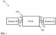
- FIG. 1 shows a schematic depiction of a portable power system 10 according to particular embodiments.
- the portable power system 10 can include a dual-drive gas turbomachine (GT) 20, such as a dual-drive gas turbine.
- the dual-drive GT 20 can include conventional GT components such as a compressor section, combustor section and turbine section, for converting the thermal energy of gas flow into rotational energy by way of two output shafts 30.
- these output shafts 30 can be configured to couple with one or more dynamoelectric machines to provide a power output, as described herein.
- the dual-drive GT 20 can be sized to fit on a roadway-compliant trailer 40 for transport to a remote location ( FIG. 2 ).
- a roadway-compliant trailer 40 can include a transportation vehicle capable of being pushed, pulled or otherwise moved over a roadway.
- transportation of physically large systems using roadways can be particularly challenging.
- Various nations, states, municipalities, etc. have restrictions on the size and weight of a load that can be carried over a roadway, e.g., due to wear-and-tear on the roadway, clearances with nearby structures (e.g., overpasses or bridges), etc. While these restrictions can vary by location, systems of significant size can be difficult to transport using existing roadways.
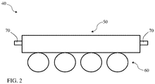
- FIG. 2 illustrates an example roadway-compliant trailer (or simply, trailer) 40 having a platform 50 for supporting a component (e.g., a dual-drive GT 20 or a dynamoelectric machine, as described herein).
- Platform 50 can be coupled with a set of wheels 60 for transporting the platform 50 along a roadway.
- trailer 40 can additionally include conventional trailer components such as couplers 70 (e.g., one or more hitches) for connecting with a truck, as well as steering controls, driving axel(s), etc.
- the roadway-compliant trailers has a dimension of approximately four (4) meters or less in height, approximately three (3) meters or less in width, and a weight of approximately 10,000 kilograms (kg) or less per axle. These dimensions may comply with roadway travel restrictions in one or more jurisdictions, such as the European Union (EU).
- EU European Union
- power system 10 can further include a pair of dynamoelectric machines (“dynamo") 80, e.g., electric generators or pumps.
- dynamo e.g., electric generators or pumps.
- the dynamoelectric machines 80 include electric generators.
- These dynamoelectric machines 80 can have an equally rated power output, such that they are rated to output an approximately equal amount of power when operated at a load (or range of loads).
- the dynamoelectric machines 80 when loaded equally, can have a higher rated output capacity than the dual-drive GT 20, such that the rated output of the power system 10 is based upon the performance of the dual-drive GT 20 (which can dependent upon inlet air temperature, altitude, fuel type, etc.).
- each dynamoelectric machine 80 can have a rated output capability of approximately 40 mega-watts (MW) at 60 degrees Fahrenheit (F) (approximately 15 degrees Celsius (C)), such that the combined capacity of the dynamoelectric machines 80 is approximately 80 MW when paired; however, the dual-drive GT 20 may only be capable of 50 MW of power at that ambient temperature (in this example). In these cases, the performance of the dual-drive GT 20 controls the maximum output of the power system 10.
- MW mega-watts
- F degrees Fahrenheit
- C degrees Celsius
- Each dynamoelectric machine 80 in the pair can include conventional dynamoelectric machine components, such as a rotor and a stator, along with sets of coils.
- Each dynamoelectric machine 80 includes an input shaft 90 that is configured (e.g., sized) to couple with one of the output shafts 30 of GT 20 and convert the rotational movement of the output shaft 30 into electrical energy.
- the shaft couplings shown in FIG. 1 are merely schematic, and not intended to depict actual coupling configurations. It is understood that any conventional shaft coupling can be used to join GT 20 and each dynamoelectric machine 80. In particular cases, each dynamoelectric machine 80 has a power output rating of less than or equal to approximately 40 MW.
- each dynamoelectric machine 80 has a power output rating of less than or equal to approximately 35 MW, and in some cases, can have a power output rating of less than or equal to approximately 30 MW. In various embodiments, the combined power output rating for the pair of dynamoelectric machines 80 is greater than approximately 50 MW. In particular cases, each dynamoelectric machine 80 has a weight less than approximately 80,000 kg in an eight (8)-axle trailer (or, approximately 10,000 kg per axle).
- Each dynamoelectric machine 80 is sized to fit on a pair of distinct roadway-compliant trailers 40 ( FIG. 2 ), which can be distinct from the roadway-compliant trailer 40 used to transport the dual-drive GT 20.
- each of the roadway-compliant trailers 40 is sized to accommodate one of the pair of dynamoelectric machines 80, or the dual-drive GT 20.
- power system 10 is configured to accommodate dynamoelectric machines 80 of different sizes/outputs.
- FIG. 3 shows a flow diagram illustrating processes in a method of configuring a power system (e.g., power system 10) at a remote location according to various embodiments, which is further described with reference to FIG. 4 .
- processes can include:
- the assembled power system 10 is configured to provide a flexible power output at the remote location. That is, the assembled power system 10 can provide a power output at a first rated level (e.g., X MW output) up to a second rated level (e.g., 2X MW output).
- the assembled power system 10 can provide a greater power output than conventional portable systems utilizing a single dynamoelectric machine, as the power output of those single-dynamoelectric machine configurations is limited by their size (and consequently, their ability to traverse roadways). Additionally, the assembled power system 10 can be easily transported via roadway and assembled in a short period due to the smaller size of the dynamoelectric machines (relative to the conventional larger-scale dynamoelectric machines).
- the power system 10 is capable of utilizing both dynamoelectric machines 80 in some cases, in other cases, one of the dynamoelectric machines 80 can be held in a standby mode and operated as a backup or supplemental dynamoelectric machine.
- the dual dynamoelectric machine 80 configuration can be beneficial in providing flexibility in power supply applications.
- one of the dynamoelectric machines 80 can be loaded to produce power while the other dynamoelectric machine 80 is used to stabilize the power grid (e.g., as a synchronous condenser).
- using one dynamoelectric machine 80 in standby mode can provide more efficient power output in dynamic demand scenarios.
- processes described herein can be iterated (repeated) periodically (e.g., according to schedule of x times per y period, and/or continuously) in order to aid in providing portable power to remote locations, e.g., in providing power system 10 to one or more remote locations.
- components described as being “coupled” to one another can be joined along one or more interfaces.
- these interfaces can include junctions between distinct components, and in other cases, these interfaces can include a solidly and/or integrally formed interconnection. That is, in some cases, components that are “coupled” to one another can be simultaneously formed to define a single continuous member.
- these coupled components can be formed as separate members and be subsequently joined through known processes (e.g., soldering, fastening, ultrasonic welding, bonding).
- electronic components described as being “coupled” can be linked via conventional hard-wired and/or wireless means such that these electronic components can communicate data with one another.
Abstract
Description
- The subject matter disclosed herein relates to power systems. More particularly, the subject matter disclosed herein relates to portable power systems and methods for configuring such systems.
- Portable power systems can be beneficial in a variety of applications. For example, during temporary operations, it may be useful to have a large power supply available for powering one or more systems. Additionally, in remote locations where a conventional large-scale power system is not practical, a portable system may be beneficial. However, conventional portable power systems are restricted by their means of transportation. These conventional systems may fail to meet the needs of the end user.
- Various embodiments include portable power systems, along with related transportation methods. A first aspect includes a portable power system having: a dual-drive gas turbomachine (GT) sized to fit on a roadway-compliant trailer; and a pair of dynamoelectric machines, each having an equally rated power output, sized to fit on the roadway-compliant trailer with the dual-drive GT, wherein each of the pair of dynamoelectric machines is configured to couple with the dual-drive GT to provide a power output at a location.
- A second aspect includes a method including: loading a power system on a set of three distinct roadway-compliant trailers for transport to a remote location, the power system having: a dual-drive gas turbomachine (GT); and a pair of dynamoelectric machines, each having an equally rated power output; and assembling the power system at the remote location, the assembling including coupling each of the pair of dynamoelectric machines with the dual-drive GT to provide a power output at the remote location.
- These and other features of this disclosure will be more readily understood from the following detailed description of the various aspects of the disclosure taken in conjunction with the accompanying drawings that depict various embodiments of the disclosure, in which:
-
FIG. 1 shows a schematic depiction of a portable power system according to various embodiments of the disclosure. -
FIG. 2 shows a perspective view of a trailer for transporting the portable power system ofFIG. 1 , according to various particular embodiments of the disclosure. -
FIG. 3 shows a flow diagram illustrating a process according to various embodiments of the disclosure. -
FIG. 4 shows a schematic depiction of a process in the flow diagram ofFIG. 3 , according to various particular embodiments of the disclosure. - It is noted that the drawings of the various aspects of the disclosure are not necessarily to scale. The drawings are intended to depict only typical aspects of the disclosure, and therefore should not be considered as limiting the scope of the disclosure. In the drawings, like numbering represents like elements between the drawings.
- As indicated herein, the subject matter disclosed relates to power systems. More particularly, the subject matter disclosed herein relates to a portable power system that is configured to meet roadway travel constraints and adapt to dynamic power demands.
- In the following description, reference is made to the accompanying drawings that form a part thereof, and in which is shown by way of illustration specific example embodiments in which the present teachings may be practiced. These embodiments are described in sufficient detail to enable those skilled in the art to practice the present teachings and it is to be understood that other embodiments may be utilized and that changes may be made without departing from the scope of the present teachings. The following description is, therefore, merely illustrative.
- As noted herein, conventional portable power systems are restricted by their means of transportation. These conventional systems may fail to meet the needs of the end user. For example, conventional power systems include a turbine (e.g., gas turbine) coupled with a dynamoelectric machine (e.g., a generator) for outputting power at a location. The power output of this system is limited by the size of the dynamoelectric machine. Because portable power systems are transported using roadways, the power output (and adaptability) of these systems is inherently limited by the transportation restrictions of those roadways.
- In contrast to conventional power systems, a portable power system capable of being transported by roadway and providing dynamic power output is disclosed according to various embodiments. In some particular cases, the portable power system includes a gas turbomachine and a pair of equally sized dynamoelectric machines sized to travel on corresponding roadway-compliant trailers. The gas turbomachine (GT) can be a dual-drive GT configured to provide output at two dynamoelectric machines simultaneously. In these cases, the equally sized dynamoelectric machines allow for shipment of the entire power system on a set of roadway-compliant trailers, and further enhance the efficiency with which such a system can be delivered and assembled. In some cases, each dynamoelectric machine has a rated mega-watt (MW) power output of less than approximately 40 MW. In particular cases, a combined power output rating for the pair of dynamoelectric machines is greater than approximately 50 MW.
- In some particular embodiments, a method includes: loading a gas turbomachine on a roadway-compliant trailer, loading a first dynamoelectric machine on the roadway-compliant trailer, loading a second dynamoelectric machine on the roadway-compliant trailer, and delivering the loaded roadway-compliant trailer to a usage location. In some cases, the method further includes unloading and/or assembling the roadway-compliant trailer at the usage location. The process of unloading/assembling can include coupling the gas turbomachine with the first dynamoelectric machine and the second dynamoelectric machine, where each of the dynamoelectric machines is coupled at a distinct end of the gas turbomachine.
-
FIG. 1 shows a schematic depiction of aportable power system 10 according to particular embodiments. In various embodiments, theportable power system 10 can include a dual-drive gas turbomachine (GT) 20, such as a dual-drive gas turbine. The dual-drive GT 20 can include conventional GT components such as a compressor section, combustor section and turbine section, for converting the thermal energy of gas flow into rotational energy by way of twooutput shafts 30. In various embodiments, theseoutput shafts 30 can be configured to couple with one or more dynamoelectric machines to provide a power output, as described herein. The dual-drive GT 20 can be sized to fit on a roadway-compliant trailer 40 for transport to a remote location (FIG. 2 ). As used herein, the term "remote location" refers to any location that can be reached by roadway, and is distinct from the present location ofportable power system 10. A roadway-compliant trailer 40 can include a transportation vehicle capable of being pushed, pulled or otherwise moved over a roadway. As described herein, transportation of physically large systems using roadways can be particularly challenging. Various nations, states, municipalities, etc. have restrictions on the size and weight of a load that can be carried over a roadway, e.g., due to wear-and-tear on the roadway, clearances with nearby structures (e.g., overpasses or bridges), etc. While these restrictions can vary by location, systems of significant size can be difficult to transport using existing roadways. -
FIG. 2 illustrates an example roadway-compliant trailer (or simply, trailer) 40 having aplatform 50 for supporting a component (e.g., a dual-drive GT 20 or a dynamoelectric machine, as described herein).Platform 50 can be coupled with a set ofwheels 60 for transporting theplatform 50 along a roadway. It is understood thattrailer 40 can additionally include conventional trailer components such as couplers 70 (e.g., one or more hitches) for connecting with a truck, as well as steering controls, driving axel(s), etc. In some cases, the roadway-compliant trailers has a dimension of approximately four (4) meters or less in height, approximately three (3) meters or less in width, and a weight of approximately 10,000 kilograms (kg) or less per axle. These dimensions may comply with roadway travel restrictions in one or more jurisdictions, such as the European Union (EU). - Returning to
FIG. 1 , in various embodiments,power system 10 can further include a pair of dynamoelectric machines ("dynamo") 80, e.g., electric generators or pumps. In particular cases, thedynamoelectric machines 80 include electric generators. Thesedynamoelectric machines 80 can have an equally rated power output, such that they are rated to output an approximately equal amount of power when operated at a load (or range of loads). Thedynamoelectric machines 80, when loaded equally, can have a higher rated output capacity than the dual-drive GT 20, such that the rated output of thepower system 10 is based upon the performance of the dual-drive GT 20 (which can dependent upon inlet air temperature, altitude, fuel type, etc.). In one example, eachdynamoelectric machine 80 can have a rated output capability of approximately 40 mega-watts (MW) at 60 degrees Fahrenheit (F) (approximately 15 degrees Celsius (C)), such that the combined capacity of thedynamoelectric machines 80 is approximately 80 MW when paired; however, the dual-drive GT 20 may only be capable of 50 MW of power at that ambient temperature (in this example). In these cases, the performance of the dual-drive GT 20 controls the maximum output of thepower system 10. - Each
dynamoelectric machine 80 in the pair can include conventional dynamoelectric machine components, such as a rotor and a stator, along with sets of coils. Eachdynamoelectric machine 80 includes aninput shaft 90 that is configured (e.g., sized) to couple with one of theoutput shafts 30 ofGT 20 and convert the rotational movement of theoutput shaft 30 into electrical energy. The shaft couplings shown inFIG. 1 are merely schematic, and not intended to depict actual coupling configurations. It is understood that any conventional shaft coupling can be used to joinGT 20 and eachdynamoelectric machine 80. In particular cases, eachdynamoelectric machine 80 has a power output rating of less than or equal to approximately 40 MW. In some more particular cases, eachdynamoelectric machine 80 has a power output rating of less than or equal to approximately 35 MW, and in some cases, can have a power output rating of less than or equal to approximately 30 MW. In various embodiments, the combined power output rating for the pair ofdynamoelectric machines 80 is greater than approximately 50 MW. In particular cases, eachdynamoelectric machine 80 has a weight less than approximately 80,000 kg in an eight (8)-axle trailer (or, approximately 10,000 kg per axle). - Each
dynamoelectric machine 80 is sized to fit on a pair of distinct roadway-compliant trailers 40 (FIG. 2 ), which can be distinct from the roadway-compliant trailer 40 used to transport the dual-drive GT 20. In other terms, each of the roadway-compliant trailers 40 is sized to accommodate one of the pair ofdynamoelectric machines 80, or the dual-drive GT 20. As the size of eachdynamoelectric machine 80 is related to its maximum rated power output,power system 10 is configured to accommodatedynamoelectric machines 80 of different sizes/outputs. -
FIG. 3 shows a flow diagram illustrating processes in a method of configuring a power system (e.g., power system 10) at a remote location according to various embodiments, which is further described with reference toFIG. 4 . As shown, processes can include: - Process P1:
loading power system 10 on a set of three distinct roadway-compliant trailers 40 for transport to a remote location (FIG. 4 ). In various implementations, this process can include loading each one of the pair ofdynamoelectric machines compliant trailer drive GT 20 on a distinct roadway-compliant trailer 40C (FIG. 4 ). This loading process can be performed in any order, e.g.,GT 20 first anddynamoelectric machines dynamoelectric machine 80A first, followed byGT 20 and then seconddynamoelectric machine 80B. According to some implementations, the loading process includes lifting the power system 10 (including distinct components such asdynamoelectric machines 80 and dual-drive GT 20) using a crane 100 (depicted in background). In some cases, the loading process can further include securing the pair ofdynamoelectric machines 80 to distinct ones of the roadway-compliant trailers adjacent ground surface 110. That is,dynamoelectric machines 80 can be clamped, tied, bolted, or otherwise coupled toplatform 50 of eachtrailer 40, and after being coupled toplatform 50, can have a height that is also roadway compliant. - Process P1A (optional): transporting the distinct loaded roadway-
compliant trailers compliant trailers compliant trailers - Process P2: assembling the
power system 10 at the remote location.FIG. 1 illustrates the assembledpower system 10 as described herein. In various embodiments, the process of assemblingpower system 10 includes coupling each of thedynamoelectric machines 80 with dual-drive GT 20. In some cases,dynamoelectric machines 80 are coupled with distinct ends 120 (FIG. 1 ) of dual-drive GT 20 (e.g., via conventional shaft coupling atoutput shafts 30 ofGT 20 andinput shaft 90 of each dynamoelectric machine 80). - The assembled
power system 10 is configured to provide a flexible power output at the remote location. That is, the assembledpower system 10 can provide a power output at a first rated level (e.g., X MW output) up to a second rated level (e.g., 2X MW output). The assembledpower system 10 can provide a greater power output than conventional portable systems utilizing a single dynamoelectric machine, as the power output of those single-dynamoelectric machine configurations is limited by their size (and consequently, their ability to traverse roadways). Additionally, the assembledpower system 10 can be easily transported via roadway and assembled in a short period due to the smaller size of the dynamoelectric machines (relative to the conventional larger-scale dynamoelectric machines). Even further, although thepower system 10 is capable of utilizing bothdynamoelectric machines 80 in some cases, in other cases, one of thedynamoelectric machines 80 can be held in a standby mode and operated as a backup or supplemental dynamoelectric machine. In some cases the dualdynamoelectric machine 80 configuration can be beneficial in providing flexibility in power supply applications. For example, in particular embodiments, one of thedynamoelectric machines 80 can be loaded to produce power while the otherdynamoelectric machine 80 is used to stabilize the power grid (e.g., as a synchronous condenser). In still other particular cases, using onedynamoelectric machine 80 in standby mode can provide more efficient power output in dynamic demand scenarios. - In various embodiments, processes described herein can be iterated (repeated) periodically (e.g., according to schedule of x times per y period, and/or continuously) in order to aid in providing portable power to remote locations, e.g., in providing
power system 10 to one or more remote locations. - It is understood that in the processes described herein, other processes may be performed while not being explicitly described, and the order of processes can be rearranged according to various embodiments. Additionally, intermediate processes may be performed between one or more described processes. The flow of processes described herein is not to be construed as limiting of the various embodiments.
- In various embodiments, components described as being "coupled" to one another can be joined along one or more interfaces. In some embodiments, these interfaces can include junctions between distinct components, and in other cases, these interfaces can include a solidly and/or integrally formed interconnection. That is, in some cases, components that are "coupled" to one another can be simultaneously formed to define a single continuous member. However, in other embodiments, these coupled components can be formed as separate members and be subsequently joined through known processes (e.g., soldering, fastening, ultrasonic welding, bonding). In various embodiments, electronic components described as being "coupled" can be linked via conventional hard-wired and/or wireless means such that these electronic components can communicate data with one another.
- This written description uses examples to disclose the invention, including the best mode, and also to enable any person skilled in the art to practice the invention, including making and using any devices or systems and performing any incorporated methods. The patentable scope of the invention is defined by the claims, and may include other examples that occur to those skilled in the art. Such other examples are intended to be within the scope of the claims if they have structural elements that do not differ from the literal language of the claims, or if they include equivalent structural elements with insubstantial differences from the literal languages of the claims.
Parts list: power system 10 dual-drive gas turbomachine (GT) 20 output shaft 30 trailer 40 platform 50 wheels 60 couplers 70 dynamoelectric machine 80 input shaft 90 crane 100 ground surface 110 distinct ends 120 dynamoelectric machine 80A second dynamoelectric machine 80B
Claims (15)
- A portable power system comprising:a dual-drive gas turbomachine (GT) sized to fit on a roadway-compliant trailer; anda pair of dynamoelectric machines, each having an equally rated power output, sized to fit on a pair of roadway-compliant trailers distinct from the roadway-compliant trailer for the GT, wherein each of the pair of dynamoelectric machines is configured to couple with the dual-drive GT to provide a power output at a location.
- The portable power system of claim 1, wherein the pair of roadway-compliant trailers includes two distinct trailers each sized to accommodate one of the pair of dynamoelectric machines.
- The portable power system of claim 1, wherein the power output rating for each of the pair of dynamoelectric machines is less than or equal to approximately 40 mega-watts (MW).
- The portable power system of claim 3, wherein a combined power output rating for the pair of dynamoelectric machines is greater than approximately 50 MW.
- The portable power system of claim 1, wherein each of the pair of dynamoelectric machines is configured to connect with a distinct end of the dual-drive GT to provide the power output at the location.
- The portable power system of claim 1, wherein each of the pair of dynamoelectric machines has a weight less than or equal to approximately 80,000 kilograms.
- The portable power system of claim 1, wherein, when loaded on the pair of roadway-compliant trailers, each of the pair of dynamoelectric machines does not exceed a maximum height of approximately four meters from an adjacent ground surface.
- The portable power system of claim 1, wherein each of the pair of roadway-compliant trailers has a dimension of approximately equal to or less than three meters wide.
- A method comprising:loading a power system on a set of three distinct roadway-compliant trailers for transport to a remote location, the power system having:a dual-drive gas turbomachine (GT); anda pair of dynamoelectric machines, each having an equally rated power output; andassembling the power system at the remote location, the assembling including coupling each of the pair of dynamoelectric machines with the dual-drive GT to provide a power output at the remote location.
- The method of claim 9, wherein the coupling includes coupling each of the pair of dynamoelectric machines to a distinct end of the dual-drive GT.
- The method of claim 9, wherein the power output rating for each of the pair of dynamoelectric machines is less than or equal to approximately 40 mega-watts (MW).
- The method of claim 11, wherein a combined power output rating for the pair of dynamoelectric machines is greater than approximately 50 MW.
- The method of claim 9, wherein each of the pair of dynamoelectric machines has a weight less than or equal to approximately 80,000 kg, and wherein the loading includes lifting the power system using a crane.
- The method of claim 9, wherein the loading of the power system on the three distinct roadway-compliant trailers includes securing each of the pair of dynamoelectric machines to a distinct one of the roadway-compliant trailers at a maximum height of less than approximately four meters from an adjacent ground surface.
- The method of claim 9, wherein the loading of the power system includes:loading the dual-drive GT on a first roadway-compliant trailer;loading a first one of the pair of dynamoelectric machines on a second roadway-compliant trailer; andloading a second one of the pair of dynamoelectric machines on a third roadway-compliant trailer.
Priority Applications (2)
| Application Number | Priority Date | Filing Date | Title |
|---|---|---|---|
| EP17461627.6A EP3476702A1 (en) | 2017-10-26 | 2017-10-26 | Portable power system and related method |
| JP2018201397A JP7286297B2 (en) | 2017-10-26 | 2018-10-26 | Portable power system and related methods |
Applications Claiming Priority (1)
| Application Number | Priority Date | Filing Date | Title |
|---|---|---|---|
| EP17461627.6A EP3476702A1 (en) | 2017-10-26 | 2017-10-26 | Portable power system and related method |
Publications (1)
| Publication Number | Publication Date |
|---|---|
| EP3476702A1 true EP3476702A1 (en) | 2019-05-01 |
Family
ID=60269791
Family Applications (1)
| Application Number | Title | Priority Date | Filing Date |
|---|---|---|---|
| EP17461627.6A Pending EP3476702A1 (en) | 2017-10-26 | 2017-10-26 | Portable power system and related method |
Country Status (2)
| Country | Link |
|---|---|
| EP (1) | EP3476702A1 (en) |
| JP (1) | JP7286297B2 (en) |
Citations (3)
| Publication number | Priority date | Publication date | Assignee | Title |
|---|---|---|---|---|
| US5575145A (en) * | 1994-11-01 | 1996-11-19 | Chevron U.S.A. Inc. | Gas turbine repair |
| CA2874948A1 (en) * | 2012-06-08 | 2013-12-12 | Nuovo Pignone Srl | Modular gas turbine plant with a heavy duty gas turbine |
| US20160356243A1 (en) * | 2012-03-23 | 2016-12-08 | Concentric Power, Inc. | Cogeneration networks |
Family Cites Families (3)
| Publication number | Priority date | Publication date | Assignee | Title |
|---|---|---|---|---|
| US9950758B2 (en) * | 2014-09-17 | 2018-04-24 | General Electric Company | Systems and methods for a turbine trailer mechanical docking and alignment system |
| CA2970542C (en) * | 2014-12-19 | 2018-09-04 | Evolution Well Services, Llc | Mobile electric power generation for hydraulic fracturing of subsurface geological formations |
| US20160308419A1 (en) * | 2015-04-20 | 2016-10-20 | General Electric Company | System and method for providing structural stability to mobile power plants |
-
2017
- 2017-10-26 EP EP17461627.6A patent/EP3476702A1/en active Pending
-
2018
- 2018-10-26 JP JP2018201397A patent/JP7286297B2/en active Active
Patent Citations (3)
| Publication number | Priority date | Publication date | Assignee | Title |
|---|---|---|---|---|
| US5575145A (en) * | 1994-11-01 | 1996-11-19 | Chevron U.S.A. Inc. | Gas turbine repair |
| US20160356243A1 (en) * | 2012-03-23 | 2016-12-08 | Concentric Power, Inc. | Cogeneration networks |
| CA2874948A1 (en) * | 2012-06-08 | 2013-12-12 | Nuovo Pignone Srl | Modular gas turbine plant with a heavy duty gas turbine |
Non-Patent Citations (2)
| Title |
|---|
| BRIAN WANG: "Siemens and Emrax claim best power to weight ratio for electric motors in the 5 to 10 kilowatt per kg range", 20 April 2015 (2015-04-20), XP055484950, Retrieved from the Internet <URL:https://www.nextbigfuture.com/2015/04/siemens-and-emrax-claim-best-power-to.html> [retrieved on 20180615] * |
| G.N. PETROV: "Elektricke stroje 2", 1982, pages 658 - 658, XP055484977, Retrieved from the Internet <URL:https://katalog.kfbz.cz/authorities/1116205> [retrieved on 20180615] * |
Also Published As
| Publication number | Publication date |
|---|---|
| JP2019085101A (en) | 2019-06-06 |
| JP7286297B2 (en) | 2023-06-05 |
Similar Documents
| Publication | Publication Date | Title |
|---|---|---|
| US7963542B2 (en) | Modular cart for a gas turbine engine | |
| KR101674932B1 (en) | Charge station of unmanned aerial vehicle, charge station including the same, method of charging unmanned aerial vehicle, and method of transporting goods using unmanned aerial vehicle | |
| US20160248230A1 (en) | Modular power plant assembly | |
| US7805893B2 (en) | Preassembled tower section of a wind power plant | |
| CN101331059A (en) | Modular aircraft ground support cart | |
| US20140208730A1 (en) | High Output Modular CAES (HOMC) | |
| US3453443A (en) | Gas turbine mobile powerplant | |
| US11746692B2 (en) | Automatic couplings for modular generator set system | |
| CN102686479B (en) | There is the aircraft of turbojet and undercarriage | |
| CN110735713A (en) | Medium-high power split vehicle-mounted gas turbine generator set | |
| CN105556066A (en) | Baseplate for mounting and supporting rotating machinery and system comprising said baseplate | |
| CN103253119A (en) | Module mounting and structure with adaptor plate | |
| EP1543242A2 (en) | Mobile power system | |
| EP2843810B1 (en) | Generator for a wind turbine | |
| US11912144B2 (en) | Self-contained renewable inductive battery charger | |
| US20190222054A1 (en) | Energy supply arrangement | |
| US20120102911A1 (en) | Engine-load connection strategy | |
| EP3476702A1 (en) | Portable power system and related method | |
| CN103016273A (en) | Nacelle for a wind turbine | |
| JP2016531243A (en) | Eccentric coupling device and method for coupling mating casing in turbomachine | |
| JP6112953B2 (en) | Wind power plant assembly method | |
| US9843238B2 (en) | Close coupled adapter for a generator set | |
| US20120227357A1 (en) | Transportation method for a wind turbine blade | |
| EP3088731B1 (en) | Transport system for transportation of a generator of a wind turbine and method for transportation of the generator | |
| CN104823355B (en) | The external structure of generator |
Legal Events
| Date | Code | Title | Description |
|---|---|---|---|
| PUAI | Public reference made under article 153(3) epc to a published international application that has entered the european phase |
Free format text: ORIGINAL CODE: 0009012 |
|
| STAA | Information on the status of an ep patent application or granted ep patent |
Free format text: STATUS: THE APPLICATION HAS BEEN PUBLISHED |
|
| AK | Designated contracting states |
Kind code of ref document: A1 Designated state(s): AL AT BE BG CH CY CZ DE DK EE ES FI FR GB GR HR HU IE IS IT LI LT LU LV MC MK MT NL NO PL PT RO RS SE SI SK SM TR |
|
| AX | Request for extension of the european patent |
Extension state: BA ME |
|
| STAA | Information on the status of an ep patent application or granted ep patent |
Free format text: STATUS: REQUEST FOR EXAMINATION WAS MADE |
|
| 17P | Request for examination filed |
Effective date: 20191031 |
|
| RBV | Designated contracting states (corrected) |
Designated state(s): AL AT BE BG CH CY CZ DE DK EE ES FI FR GB GR HR HU IE IS IT LI LT LU LV MC MK MT NL NO PL PT RO RS SE SI SK SM TR |
|
| STAA | Information on the status of an ep patent application or granted ep patent |
Free format text: STATUS: EXAMINATION IS IN PROGRESS |
|
| 17Q | First examination report despatched |
Effective date: 20210129 |
|
| STAA | Information on the status of an ep patent application or granted ep patent |
Free format text: STATUS: EXAMINATION IS IN PROGRESS |
|
| RAP1 | Party data changed (applicant data changed or rights of an application transferred) |
Owner name: GENERAL ELECTRIC TECHNOLOGY GMBH |