EP3476680A1 - Method for heating an exhaust aftertreatment system and a hybrid vehicle adapted to heat an exhaust aftertreatment system - Google Patents
Method for heating an exhaust aftertreatment system and a hybrid vehicle adapted to heat an exhaust aftertreatment system Download PDFInfo
- Publication number
- EP3476680A1 EP3476680A1 EP17197979.2A EP17197979A EP3476680A1 EP 3476680 A1 EP3476680 A1 EP 3476680A1 EP 17197979 A EP17197979 A EP 17197979A EP 3476680 A1 EP3476680 A1 EP 3476680A1
- Authority
- EP
- European Patent Office
- Prior art keywords
- exhaust
- aftertreatment system
- electric machine
- exhaust aftertreatment
- predefined limit
- Prior art date
- Legal status (The legal status is an assumption and is not a legal conclusion. Google has not performed a legal analysis and makes no representation as to the accuracy of the status listed.)
- Granted
Links
Images

Classifications
-
- F—MECHANICAL ENGINEERING; LIGHTING; HEATING; WEAPONS; BLASTING
- F02—COMBUSTION ENGINES; HOT-GAS OR COMBUSTION-PRODUCT ENGINE PLANTS
- F02N—STARTING OF COMBUSTION ENGINES; STARTING AIDS FOR SUCH ENGINES, NOT OTHERWISE PROVIDED FOR
- F02N11/00—Starting of engines by means of electric motors
- F02N11/08—Circuits specially adapted for starting of engines
- F02N11/0814—Circuits specially adapted for starting of engines comprising means for controlling automatic idle-start-stop
- F02N11/0818—Conditions for starting or stopping the engine or for deactivating the idle-start-stop mode
- F02N11/0829—Conditions for starting or stopping the engine or for deactivating the idle-start-stop mode related to special engine control, e.g. giving priority to engine warming-up or learning
-
- B—PERFORMING OPERATIONS; TRANSPORTING
- B60—VEHICLES IN GENERAL
- B60W—CONJOINT CONTROL OF VEHICLE SUB-UNITS OF DIFFERENT TYPE OR DIFFERENT FUNCTION; CONTROL SYSTEMS SPECIALLY ADAPTED FOR HYBRID VEHICLES; ROAD VEHICLE DRIVE CONTROL SYSTEMS FOR PURPOSES NOT RELATED TO THE CONTROL OF A PARTICULAR SUB-UNIT
- B60W20/00—Control systems specially adapted for hybrid vehicles
- B60W20/10—Controlling the power contribution of each of the prime movers to meet required power demand
- B60W20/15—Control strategies specially adapted for achieving a particular effect
- B60W20/16—Control strategies specially adapted for achieving a particular effect for reducing engine exhaust emissions
-
- B—PERFORMING OPERATIONS; TRANSPORTING
- B60—VEHICLES IN GENERAL
- B60K—ARRANGEMENT OR MOUNTING OF PROPULSION UNITS OR OF TRANSMISSIONS IN VEHICLES; ARRANGEMENT OR MOUNTING OF PLURAL DIVERSE PRIME-MOVERS IN VEHICLES; AUXILIARY DRIVES FOR VEHICLES; INSTRUMENTATION OR DASHBOARDS FOR VEHICLES; ARRANGEMENTS IN CONNECTION WITH COOLING, AIR INTAKE, GAS EXHAUST OR FUEL SUPPLY OF PROPULSION UNITS IN VEHICLES
- B60K6/00—Arrangement or mounting of plural diverse prime-movers for mutual or common propulsion, e.g. hybrid propulsion systems comprising electric motors and internal combustion engines
- B60K6/20—Arrangement or mounting of plural diverse prime-movers for mutual or common propulsion, e.g. hybrid propulsion systems comprising electric motors and internal combustion engines the prime-movers consisting of electric motors and internal combustion engines, e.g. HEVs
- B60K6/22—Arrangement or mounting of plural diverse prime-movers for mutual or common propulsion, e.g. hybrid propulsion systems comprising electric motors and internal combustion engines the prime-movers consisting of electric motors and internal combustion engines, e.g. HEVs characterised by apparatus, components or means specially adapted for HEVs
-
- B—PERFORMING OPERATIONS; TRANSPORTING
- B60—VEHICLES IN GENERAL
- B60W—CONJOINT CONTROL OF VEHICLE SUB-UNITS OF DIFFERENT TYPE OR DIFFERENT FUNCTION; CONTROL SYSTEMS SPECIALLY ADAPTED FOR HYBRID VEHICLES; ROAD VEHICLE DRIVE CONTROL SYSTEMS FOR PURPOSES NOT RELATED TO THE CONTROL OF A PARTICULAR SUB-UNIT
- B60W10/00—Conjoint control of vehicle sub-units of different type or different function
- B60W10/04—Conjoint control of vehicle sub-units of different type or different function including control of propulsion units
- B60W10/06—Conjoint control of vehicle sub-units of different type or different function including control of propulsion units including control of combustion engines
-
- B—PERFORMING OPERATIONS; TRANSPORTING
- B60—VEHICLES IN GENERAL
- B60W—CONJOINT CONTROL OF VEHICLE SUB-UNITS OF DIFFERENT TYPE OR DIFFERENT FUNCTION; CONTROL SYSTEMS SPECIALLY ADAPTED FOR HYBRID VEHICLES; ROAD VEHICLE DRIVE CONTROL SYSTEMS FOR PURPOSES NOT RELATED TO THE CONTROL OF A PARTICULAR SUB-UNIT
- B60W10/00—Conjoint control of vehicle sub-units of different type or different function
- B60W10/04—Conjoint control of vehicle sub-units of different type or different function including control of propulsion units
- B60W10/08—Conjoint control of vehicle sub-units of different type or different function including control of propulsion units including control of electric propulsion units, e.g. motors or generators
-
- B—PERFORMING OPERATIONS; TRANSPORTING
- B60—VEHICLES IN GENERAL
- B60W—CONJOINT CONTROL OF VEHICLE SUB-UNITS OF DIFFERENT TYPE OR DIFFERENT FUNCTION; CONTROL SYSTEMS SPECIALLY ADAPTED FOR HYBRID VEHICLES; ROAD VEHICLE DRIVE CONTROL SYSTEMS FOR PURPOSES NOT RELATED TO THE CONTROL OF A PARTICULAR SUB-UNIT
- B60W10/00—Conjoint control of vehicle sub-units of different type or different function
- B60W10/24—Conjoint control of vehicle sub-units of different type or different function including control of energy storage means
- B60W10/26—Conjoint control of vehicle sub-units of different type or different function including control of energy storage means for electrical energy, e.g. batteries or capacitors
-
- B—PERFORMING OPERATIONS; TRANSPORTING
- B60—VEHICLES IN GENERAL
- B60W—CONJOINT CONTROL OF VEHICLE SUB-UNITS OF DIFFERENT TYPE OR DIFFERENT FUNCTION; CONTROL SYSTEMS SPECIALLY ADAPTED FOR HYBRID VEHICLES; ROAD VEHICLE DRIVE CONTROL SYSTEMS FOR PURPOSES NOT RELATED TO THE CONTROL OF A PARTICULAR SUB-UNIT
- B60W10/00—Conjoint control of vehicle sub-units of different type or different function
- B60W10/30—Conjoint control of vehicle sub-units of different type or different function including control of auxiliary equipment, e.g. air-conditioning compressors or oil pumps
-
- F—MECHANICAL ENGINEERING; LIGHTING; HEATING; WEAPONS; BLASTING
- F01—MACHINES OR ENGINES IN GENERAL; ENGINE PLANTS IN GENERAL; STEAM ENGINES
- F01N—GAS-FLOW SILENCERS OR EXHAUST APPARATUS FOR MACHINES OR ENGINES IN GENERAL; GAS-FLOW SILENCERS OR EXHAUST APPARATUS FOR INTERNAL-COMBUSTION ENGINES
- F01N11/00—Monitoring or diagnostic devices for exhaust-gas treatment apparatus
- F01N11/002—Monitoring or diagnostic devices for exhaust-gas treatment apparatus the diagnostic devices measuring or estimating temperature or pressure in, or downstream of the exhaust apparatus
-
- F—MECHANICAL ENGINEERING; LIGHTING; HEATING; WEAPONS; BLASTING
- F01—MACHINES OR ENGINES IN GENERAL; ENGINE PLANTS IN GENERAL; STEAM ENGINES
- F01N—GAS-FLOW SILENCERS OR EXHAUST APPARATUS FOR MACHINES OR ENGINES IN GENERAL; GAS-FLOW SILENCERS OR EXHAUST APPARATUS FOR INTERNAL-COMBUSTION ENGINES
- F01N11/00—Monitoring or diagnostic devices for exhaust-gas treatment apparatus
- F01N11/007—Monitoring or diagnostic devices for exhaust-gas treatment apparatus the diagnostic devices measuring oxygen or air concentration downstream of the exhaust apparatus
-
- F—MECHANICAL ENGINEERING; LIGHTING; HEATING; WEAPONS; BLASTING
- F01—MACHINES OR ENGINES IN GENERAL; ENGINE PLANTS IN GENERAL; STEAM ENGINES
- F01N—GAS-FLOW SILENCERS OR EXHAUST APPARATUS FOR MACHINES OR ENGINES IN GENERAL; GAS-FLOW SILENCERS OR EXHAUST APPARATUS FOR INTERNAL-COMBUSTION ENGINES
- F01N13/00—Exhaust or silencing apparatus characterised by constructional features
- F01N13/009—Exhaust or silencing apparatus characterised by constructional features having two or more separate purifying devices arranged in series
-
- F—MECHANICAL ENGINEERING; LIGHTING; HEATING; WEAPONS; BLASTING
- F01—MACHINES OR ENGINES IN GENERAL; ENGINE PLANTS IN GENERAL; STEAM ENGINES
- F01N—GAS-FLOW SILENCERS OR EXHAUST APPARATUS FOR MACHINES OR ENGINES IN GENERAL; GAS-FLOW SILENCERS OR EXHAUST APPARATUS FOR INTERNAL-COMBUSTION ENGINES
- F01N3/00—Exhaust or silencing apparatus having means for purifying, rendering innocuous, or otherwise treating exhaust
- F01N3/02—Exhaust or silencing apparatus having means for purifying, rendering innocuous, or otherwise treating exhaust for cooling, or for removing solid constituents of, exhaust
- F01N3/021—Exhaust or silencing apparatus having means for purifying, rendering innocuous, or otherwise treating exhaust for cooling, or for removing solid constituents of, exhaust by means of filters
-
- F—MECHANICAL ENGINEERING; LIGHTING; HEATING; WEAPONS; BLASTING
- F01—MACHINES OR ENGINES IN GENERAL; ENGINE PLANTS IN GENERAL; STEAM ENGINES
- F01N—GAS-FLOW SILENCERS OR EXHAUST APPARATUS FOR MACHINES OR ENGINES IN GENERAL; GAS-FLOW SILENCERS OR EXHAUST APPARATUS FOR INTERNAL-COMBUSTION ENGINES
- F01N3/00—Exhaust or silencing apparatus having means for purifying, rendering innocuous, or otherwise treating exhaust
- F01N3/02—Exhaust or silencing apparatus having means for purifying, rendering innocuous, or otherwise treating exhaust for cooling, or for removing solid constituents of, exhaust
- F01N3/021—Exhaust or silencing apparatus having means for purifying, rendering innocuous, or otherwise treating exhaust for cooling, or for removing solid constituents of, exhaust by means of filters
- F01N3/023—Exhaust or silencing apparatus having means for purifying, rendering innocuous, or otherwise treating exhaust for cooling, or for removing solid constituents of, exhaust by means of filters using means for regenerating the filters, e.g. by burning trapped particles
- F01N3/027—Exhaust or silencing apparatus having means for purifying, rendering innocuous, or otherwise treating exhaust for cooling, or for removing solid constituents of, exhaust by means of filters using means for regenerating the filters, e.g. by burning trapped particles using electric or magnetic heating means
-
- F—MECHANICAL ENGINEERING; LIGHTING; HEATING; WEAPONS; BLASTING
- F01—MACHINES OR ENGINES IN GENERAL; ENGINE PLANTS IN GENERAL; STEAM ENGINES
- F01N—GAS-FLOW SILENCERS OR EXHAUST APPARATUS FOR MACHINES OR ENGINES IN GENERAL; GAS-FLOW SILENCERS OR EXHAUST APPARATUS FOR INTERNAL-COMBUSTION ENGINES
- F01N3/00—Exhaust or silencing apparatus having means for purifying, rendering innocuous, or otherwise treating exhaust
- F01N3/08—Exhaust or silencing apparatus having means for purifying, rendering innocuous, or otherwise treating exhaust for rendering innocuous
- F01N3/10—Exhaust or silencing apparatus having means for purifying, rendering innocuous, or otherwise treating exhaust for rendering innocuous by thermal or catalytic conversion of noxious components of exhaust
- F01N3/18—Exhaust or silencing apparatus having means for purifying, rendering innocuous, or otherwise treating exhaust for rendering innocuous by thermal or catalytic conversion of noxious components of exhaust characterised by methods of operation; Control
- F01N3/20—Exhaust or silencing apparatus having means for purifying, rendering innocuous, or otherwise treating exhaust for rendering innocuous by thermal or catalytic conversion of noxious components of exhaust characterised by methods of operation; Control specially adapted for catalytic conversion
- F01N3/2006—Periodically heating or cooling catalytic reactors, e.g. at cold starting or overheating
-
- F—MECHANICAL ENGINEERING; LIGHTING; HEATING; WEAPONS; BLASTING
- F01—MACHINES OR ENGINES IN GENERAL; ENGINE PLANTS IN GENERAL; STEAM ENGINES
- F01N—GAS-FLOW SILENCERS OR EXHAUST APPARATUS FOR MACHINES OR ENGINES IN GENERAL; GAS-FLOW SILENCERS OR EXHAUST APPARATUS FOR INTERNAL-COMBUSTION ENGINES
- F01N3/00—Exhaust or silencing apparatus having means for purifying, rendering innocuous, or otherwise treating exhaust
- F01N3/08—Exhaust or silencing apparatus having means for purifying, rendering innocuous, or otherwise treating exhaust for rendering innocuous
- F01N3/10—Exhaust or silencing apparatus having means for purifying, rendering innocuous, or otherwise treating exhaust for rendering innocuous by thermal or catalytic conversion of noxious components of exhaust
- F01N3/18—Exhaust or silencing apparatus having means for purifying, rendering innocuous, or otherwise treating exhaust for rendering innocuous by thermal or catalytic conversion of noxious components of exhaust characterised by methods of operation; Control
- F01N3/20—Exhaust or silencing apparatus having means for purifying, rendering innocuous, or otherwise treating exhaust for rendering innocuous by thermal or catalytic conversion of noxious components of exhaust characterised by methods of operation; Control specially adapted for catalytic conversion
- F01N3/2006—Periodically heating or cooling catalytic reactors, e.g. at cold starting or overheating
- F01N3/2013—Periodically heating or cooling catalytic reactors, e.g. at cold starting or overheating using electric or magnetic heating means
-
- F—MECHANICAL ENGINEERING; LIGHTING; HEATING; WEAPONS; BLASTING
- F02—COMBUSTION ENGINES; HOT-GAS OR COMBUSTION-PRODUCT ENGINE PLANTS
- F02N—STARTING OF COMBUSTION ENGINES; STARTING AIDS FOR SUCH ENGINES, NOT OTHERWISE PROVIDED FOR
- F02N11/00—Starting of engines by means of electric motors
- F02N11/04—Starting of engines by means of electric motors the motors being associated with current generators
-
- F—MECHANICAL ENGINEERING; LIGHTING; HEATING; WEAPONS; BLASTING
- F02—COMBUSTION ENGINES; HOT-GAS OR COMBUSTION-PRODUCT ENGINE PLANTS
- F02N—STARTING OF COMBUSTION ENGINES; STARTING AIDS FOR SUCH ENGINES, NOT OTHERWISE PROVIDED FOR
- F02N11/00—Starting of engines by means of electric motors
- F02N11/08—Circuits specially adapted for starting of engines
- F02N11/0862—Circuits specially adapted for starting of engines characterised by the electrical power supply means, e.g. battery
-
- B—PERFORMING OPERATIONS; TRANSPORTING
- B60—VEHICLES IN GENERAL
- B60W—CONJOINT CONTROL OF VEHICLE SUB-UNITS OF DIFFERENT TYPE OR DIFFERENT FUNCTION; CONTROL SYSTEMS SPECIALLY ADAPTED FOR HYBRID VEHICLES; ROAD VEHICLE DRIVE CONTROL SYSTEMS FOR PURPOSES NOT RELATED TO THE CONTROL OF A PARTICULAR SUB-UNIT
- B60W2510/00—Input parameters relating to a particular sub-units
- B60W2510/06—Combustion engines, Gas turbines
- B60W2510/068—Engine exhaust temperature
-
- B—PERFORMING OPERATIONS; TRANSPORTING
- B60—VEHICLES IN GENERAL
- B60W—CONJOINT CONTROL OF VEHICLE SUB-UNITS OF DIFFERENT TYPE OR DIFFERENT FUNCTION; CONTROL SYSTEMS SPECIALLY ADAPTED FOR HYBRID VEHICLES; ROAD VEHICLE DRIVE CONTROL SYSTEMS FOR PURPOSES NOT RELATED TO THE CONTROL OF A PARTICULAR SUB-UNIT
- B60W2510/00—Input parameters relating to a particular sub-units
- B60W2510/24—Energy storage means
- B60W2510/242—Energy storage means for electrical energy
- B60W2510/244—Charge state
-
- B—PERFORMING OPERATIONS; TRANSPORTING
- B60—VEHICLES IN GENERAL
- B60W—CONJOINT CONTROL OF VEHICLE SUB-UNITS OF DIFFERENT TYPE OR DIFFERENT FUNCTION; CONTROL SYSTEMS SPECIALLY ADAPTED FOR HYBRID VEHICLES; ROAD VEHICLE DRIVE CONTROL SYSTEMS FOR PURPOSES NOT RELATED TO THE CONTROL OF A PARTICULAR SUB-UNIT
- B60W2530/00—Input parameters relating to vehicle conditions or values, not covered by groups B60W2510/00 or B60W2520/00
- B60W2530/12—Catalyst or filter state
-
- B—PERFORMING OPERATIONS; TRANSPORTING
- B60—VEHICLES IN GENERAL
- B60W—CONJOINT CONTROL OF VEHICLE SUB-UNITS OF DIFFERENT TYPE OR DIFFERENT FUNCTION; CONTROL SYSTEMS SPECIALLY ADAPTED FOR HYBRID VEHICLES; ROAD VEHICLE DRIVE CONTROL SYSTEMS FOR PURPOSES NOT RELATED TO THE CONTROL OF A PARTICULAR SUB-UNIT
- B60W2710/00—Output or target parameters relating to a particular sub-units
- B60W2710/06—Combustion engines, Gas turbines
- B60W2710/0666—Engine torque
-
- B—PERFORMING OPERATIONS; TRANSPORTING
- B60—VEHICLES IN GENERAL
- B60W—CONJOINT CONTROL OF VEHICLE SUB-UNITS OF DIFFERENT TYPE OR DIFFERENT FUNCTION; CONTROL SYSTEMS SPECIALLY ADAPTED FOR HYBRID VEHICLES; ROAD VEHICLE DRIVE CONTROL SYSTEMS FOR PURPOSES NOT RELATED TO THE CONTROL OF A PARTICULAR SUB-UNIT
- B60W2710/00—Output or target parameters relating to a particular sub-units
- B60W2710/08—Electric propulsion units
-
- B—PERFORMING OPERATIONS; TRANSPORTING
- B60—VEHICLES IN GENERAL
- B60W—CONJOINT CONTROL OF VEHICLE SUB-UNITS OF DIFFERENT TYPE OR DIFFERENT FUNCTION; CONTROL SYSTEMS SPECIALLY ADAPTED FOR HYBRID VEHICLES; ROAD VEHICLE DRIVE CONTROL SYSTEMS FOR PURPOSES NOT RELATED TO THE CONTROL OF A PARTICULAR SUB-UNIT
- B60W2710/00—Output or target parameters relating to a particular sub-units
- B60W2710/24—Energy storage means
- B60W2710/242—Energy storage means for electrical energy
- B60W2710/244—Charge state
-
- F—MECHANICAL ENGINEERING; LIGHTING; HEATING; WEAPONS; BLASTING
- F01—MACHINES OR ENGINES IN GENERAL; ENGINE PLANTS IN GENERAL; STEAM ENGINES
- F01N—GAS-FLOW SILENCERS OR EXHAUST APPARATUS FOR MACHINES OR ENGINES IN GENERAL; GAS-FLOW SILENCERS OR EXHAUST APPARATUS FOR INTERNAL-COMBUSTION ENGINES
- F01N2590/00—Exhaust or silencing apparatus adapted to particular use, e.g. for military applications, airplanes, submarines
- F01N2590/11—Exhaust or silencing apparatus adapted to particular use, e.g. for military applications, airplanes, submarines for hybrid vehicles
-
- Y—GENERAL TAGGING OF NEW TECHNOLOGICAL DEVELOPMENTS; GENERAL TAGGING OF CROSS-SECTIONAL TECHNOLOGIES SPANNING OVER SEVERAL SECTIONS OF THE IPC; TECHNICAL SUBJECTS COVERED BY FORMER USPC CROSS-REFERENCE ART COLLECTIONS [XRACs] AND DIGESTS
- Y02—TECHNOLOGIES OR APPLICATIONS FOR MITIGATION OR ADAPTATION AGAINST CLIMATE CHANGE
- Y02A—TECHNOLOGIES FOR ADAPTATION TO CLIMATE CHANGE
- Y02A50/00—TECHNOLOGIES FOR ADAPTATION TO CLIMATE CHANGE in human health protection, e.g. against extreme weather
- Y02A50/20—Air quality improvement or preservation, e.g. vehicle emission control or emission reduction by using catalytic converters
-
- Y—GENERAL TAGGING OF NEW TECHNOLOGICAL DEVELOPMENTS; GENERAL TAGGING OF CROSS-SECTIONAL TECHNOLOGIES SPANNING OVER SEVERAL SECTIONS OF THE IPC; TECHNICAL SUBJECTS COVERED BY FORMER USPC CROSS-REFERENCE ART COLLECTIONS [XRACs] AND DIGESTS
- Y02—TECHNOLOGIES OR APPLICATIONS FOR MITIGATION OR ADAPTATION AGAINST CLIMATE CHANGE
- Y02T—CLIMATE CHANGE MITIGATION TECHNOLOGIES RELATED TO TRANSPORTATION
- Y02T10/00—Road transport of goods or passengers
- Y02T10/10—Internal combustion engine [ICE] based vehicles
- Y02T10/12—Improving ICE efficiencies
-
- Y—GENERAL TAGGING OF NEW TECHNOLOGICAL DEVELOPMENTS; GENERAL TAGGING OF CROSS-SECTIONAL TECHNOLOGIES SPANNING OVER SEVERAL SECTIONS OF THE IPC; TECHNICAL SUBJECTS COVERED BY FORMER USPC CROSS-REFERENCE ART COLLECTIONS [XRACs] AND DIGESTS
- Y02—TECHNOLOGIES OR APPLICATIONS FOR MITIGATION OR ADAPTATION AGAINST CLIMATE CHANGE
- Y02T—CLIMATE CHANGE MITIGATION TECHNOLOGIES RELATED TO TRANSPORTATION
- Y02T10/00—Road transport of goods or passengers
- Y02T10/10—Internal combustion engine [ICE] based vehicles
- Y02T10/40—Engine management systems
-
- Y—GENERAL TAGGING OF NEW TECHNOLOGICAL DEVELOPMENTS; GENERAL TAGGING OF CROSS-SECTIONAL TECHNOLOGIES SPANNING OVER SEVERAL SECTIONS OF THE IPC; TECHNICAL SUBJECTS COVERED BY FORMER USPC CROSS-REFERENCE ART COLLECTIONS [XRACs] AND DIGESTS
- Y02—TECHNOLOGIES OR APPLICATIONS FOR MITIGATION OR ADAPTATION AGAINST CLIMATE CHANGE
- Y02T—CLIMATE CHANGE MITIGATION TECHNOLOGIES RELATED TO TRANSPORTATION
- Y02T10/00—Road transport of goods or passengers
- Y02T10/60—Other road transportation technologies with climate change mitigation effect
- Y02T10/62—Hybrid vehicles
Definitions
- the present invention relates to a method for heating an exhaust aftertreatment system of a hybrid vehicle comprising an internal combustion engine.
- a method for heating an exhaust aftertreatment system in a hybrid vehicle comprising an internal combustion engine and an electric machine, the steps of determining the exhaust condition for the function of the exhaust aftertreatment system, determining if the exhaust condition is below a predefined limit, applying a load from the electric machine on the internal combustion engine when the exhaust condition is below the predefined limit, in order to increase the combustion engine torque, charging the battery system of the vehicle with power from the electric machine, disconnecting the electric machine from the internal combustion engine when the exhaust condition for the function of the exhaust aftertreatment system is above the predefined limit are comprised.
- an electric machine is used to apply an additional load on the internal combustion engine, which will allow the internal combustion engine to deliver increased torque. At the same time, more heat will be produced which will heat the exhaust aftertreatment system.
- the electric machine will at the same time produce electric energy, which is used to charge the battery system of the vehicle. In this way, most of the energy used to heat the exhaust aftertreatment system can be preserved and less energy is thus lost.
- the additional electric energy from the electric motor is used to heat the exhaust aftertreatment system by using an electric heater arranged in the exhaust aftertreatment system. This will allow the exhaust aftertreatment system to heat up even faster, which will preserve some fuel. It is also possible to heat the air intake with an electric heater in order to heat the intake air.
- a vehicle where the energy losses during heating of the exhaust aftertreatment system can be reduced.
- the electric machine will apply a load to the internal combustion engine such that the torque of the internal combustion engine is increased.
- the exhaust gases will thus heat up faster which will bring the exhaust aftertreatment system to its working temperature quicker.
- the energy produced by the electric machine is used to charge the battery system of the hybrid vehicle.
- the exhaust system of the hybrid vehicle comprises a catalytic converter 5 and may also comprise a particulate filter 6 which are mounted at the exhaust pipe of the vehicle.
- the hybrid vehicle comprises a battery system 7 which is adapted to power the electric machine when the electric machine is used as an electric motor.
- the battery system is further adapted to be charged by the electric machine when the electric machine is used as a generator, or from the grid by a charge station.
- the nominal voltage of the battery system is at least 48 volts and is preferably in the region between 200 - 300 Volts.
- a passenger car is used as an example of a hybrid vehicle.
- the catalytic converter 5 is provided with an electrical heater 12 which can be powered by the electric machine or by the battery system through a converter unit 8 controlled by a control unit 9.
- the converter unit is connected to the electric machine and to the battery system and converts the voltage from the electric machine to the battery system and from the battery system to the electric machine.
- the electric machine may e.g. be a three-phase electric machine and the battery system is a direct current battery.
- the converter unit will function as an AC/DC converter and may also convert the voltage level.
- the converter unit is controlled by a control unit 9 which may be a stand-alone unit or which may be integrated in another control unit of the vehicle, or may be integrated in the converter unit.
- the electrical heater 12 is preferably mounted inside the catalytic converter, preferably at the section closest to the inlet of the catalytic converter in order to optimize the performance of the catalytic converter.
- the hybrid vehicle 1 comprises a particulate filter 6 which is provided with an electric heater 13 adapted to heat the particulate filter from the electric machine.
- the particulate filter is adapted to the fuel used by the vehicle.
- a diesel particulate regeneration filter is used to reduce the amount of soot in the exhaust gas.
- a particulate filter may also be used to reduce the amount of particles in the exhaust gas, if required by legislative regulations.
- the control unit 9 can measure an exhaust condition for the function of the exhaust aftertreatment system with a first exhaust sensor 14.
- a second exhaust sensor 15 can be used to measure the result of the exhaust aftertreatment system, i.e. the function of the exhaust aftertreatment system.
- the first exhaust sensor 14 is positioned before the exhaust aftertreatment system 10 and the second exhaust sensor 15 is positioned after the exhaust aftertreatment system 10.
- the exhaust aftertreatment system When the vehicle is cold started, i.e. started when the engine is cold and when the vehicle has not been driven for a longer time, the exhaust aftertreatment system will be cold and the catalyst converter will not be able to reduce the NOx level of the exhaust emissions.
- the control unit will detect that the exhaust condition for the function of the exhaust aftertreatment system is below a predefined limit, and will apply a load from the electric machine to the internal combustion engine, such that the torque of the internal combustion engine is raised. This will produce more hot exhaust gases which will heat the exhaust aftertreatment system, which in the shown example is the catalyst converter.
- the catalyst converter When the exhaust condition for the function of the exhaust aftertreatment system has reached the predefined limit, the catalyst converter will function properly and will reduce NOx emissions.
- the exhaust condition for the function of the exhaust aftertreatment system may be based on at least one of the following parameters; exhaust gas temperature, exhaust gas soot, exhaust gas NOx, exhaust gas flow.
- the exhaust sensor 14 may comprise several different sensor elements adapted to measure different parameters. One or more values from the exhaust sensor are read by the control unit 9, and an exhaust condition is determined by the control unit.
- the battery system will in a first example be charged by the electric machine when the electric machine applies an excessive load on the internal combustion engine.
- the battery system has been charged during the still-stand by an external charger station and is fully charged.
- a fully charged battery may have a certain headroom such that the theoretical SOC value is not utilized completely when charging the battery system by a charger station. By avoiding to charge the battery to a SOC level of 100 %, the life of the battery system is prolonged.
- the SOC level of a battery system fully charged by a charger station may be in the range between 80-90 % of the theoretical SOC value.
- the additional headroom can be used for regenerative charging when the vehicle is driven, which reduces the risk of overcharging the battery.
- the battery system is charged by the electric machine.
- the additional charge of the battery can later be used e.g. to power the vehicle when driven in a hybrid mode, where the electric machine acts as an electric motor.
- the battery system has been charged during the still-stand by an external charger station and is fully charged.
- the battery system is charged to a higher level, e.g. to a SOC level above 90 % of the theoretical SOC value.
- a SOC level above 90 % of the theoretical SOC value.
- the battery system will thus not be charged by the electric machine.
- the additional energy from the electric machine will be used to heat the catalytic converter by the electric heater mounted in the catalytic converter. This will allow the exhaust aftertreatment system to heat up even faster, which will preserve some fuel.
- a particulate filter may be heated by the additional electric energy from the electric machine, or the air intake is heated with an electric heater.
- the control unit measures the exhaust condition for the function of the exhaust aftertreatment system. If the exhaust condition is above a predefined limit, there is no need to apply an additional torque to the internal combustion engine by the electric machine, since the exhaust aftertreatment system will be able to reduce NOx right from the start. In this case, the battery system is not charged by the electric machine.
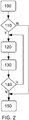
- Fig. 2 shows a schematic flow chart of the method for heating an exhaust aftertreatment system in a hybrid vehicle.
- the method is performed when the vehicle has been started, either when it is cold started or restarted with a warm engine.
- the method steps are preferably performed by a computer program and a computer program product contained and run in the electronic control unit of the vehicle.
- the exhaust condition for the function of the exhaust aftertreatment system is determined by a control unit, based on measurements from an exhaust sensor mounted at the exhaust aftertreatment system.
- the exhaust sensor measures one or more of the exhaust gas temperature, the exhaust gas soot, the exhaust gas NOx and/or the exhaust gas flow.
- the exhaust aftertreatment system is often a catalytic converter, which is provided with an exhaust sensor at the inlet of the catalytic converter.
- step 110 it is determined if the exhaust condition for the function of the exhaust aftertreatment system is below a predefined limit.
- the predefined limit may e.g. be based on the lowest working temperature of the exhaust aftertreatment system or on the NOx level in the exhaust gas. If the exhaust condition is below the predefined limit, the method continues with step 120, otherwise the method continues with step 150, i.e. no additional heating of the exhaust aftertreatment system is required.
- step 120 a load from the electric machine is applied on the internal combustion engine, in order to increase the internal combustion engine torque. This additional load will increase the exhaust gas temperature, such that the exhaust aftertreatment system will heat up faster.
- step 130 the battery system of the vehicle is charged with power from the electric machine. This continues until the exhaust condition for the function of the exhaust aftertreatment system has reached the predefined limit, e.g. where the working temperature of the exhaust aftertreatment system is reached.
- step 140 the exhaust condition for the function of the exhaust aftertreatment system is compared to the predefined limit. If the exhaust condition for the function of the exhaust aftertreatment system is lower than the predefined limit, the charging of the battery continues. When the exhaust condition for the function of the exhaust aftertreatment system is equal to the predefined limit, the working condition of the exhaust aftertreatment system is reached, e.g. the working temperature of the catalytic converter is reached. The method is then terminated at step 150.
Landscapes
- Engineering & Computer Science (AREA)
- Chemical & Material Sciences (AREA)
- Combustion & Propulsion (AREA)
- Mechanical Engineering (AREA)
- General Engineering & Computer Science (AREA)
- Chemical Kinetics & Catalysis (AREA)
- Transportation (AREA)
- Toxicology (AREA)
- Health & Medical Sciences (AREA)
- Automation & Control Theory (AREA)
- Hybrid Electric Vehicles (AREA)
- Exhaust Gas After Treatment (AREA)
- Processes For Solid Components From Exhaust (AREA)
- Control Of Vehicle Engines Or Engines For Specific Uses (AREA)
Abstract
Description
- The present invention relates to a method for heating an exhaust aftertreatment system of a hybrid vehicle comprising an internal combustion engine.
- Vehicles comprising an internal combustion engine are subjected to a plurality of different legislative requirements and regulations. Some of these requirements and regulations are directed to fuel consumption and exhaust emission. Different countries or markets may have different requirements, but most include a specific test cycle that is supposed to give an indication of the fuel consumption and exhaust emission of the vehicle. However, there is normally a discrepancy between the fuel consumption and exhaust emission measured in a test cycle and the same measured in real world driving conditions.
- A real world cold start is normally performed in a large temperature interval, which may start at -40 degrees Celsius and may end at 40 degrees Celsius. During a cold start, the fuel consumption will be higher, mainly due to higher friction in the engine and in the transmission. The exhaust emission will also be higher, mainly due to that the exhaust aftertreatment system has not reached the optimal working temperature.
- In order to minimize the exhaust emissions when the vehicle is started, it is known to run the engine with suboptimal combustion parameters, i.e. the combustion is run with more fuel than necessary and the ignition is adjusted to ignite the fuel mixture with a non-optimal timing. In this way, more heat is produced by the internal combustion engine which will heat the exhaust aftertreatment system in a faster way, such that the exhaust aftertreatment system can start to reduce exhaust emissions as quick as possible. Such a method works well most of the time, but there are energy losses.
- There is thus room for a method that improves the heating of the exhaust aftertreatment system of a hybrid vehicle.
- An object of the invention is therefore to provide an improved method for heating the exhaust aftertreatment system of a hybrid vehicle. A further object of the invention is to provide a hybrid vehicle that is adapted to heat the exhaust aftertreatment system in an improved way.
- The solution to the problem according to the invention is described in the characterizing part of claim 1 regarding the method and in claim 8 regarding the vehicle. The other claims contain advantageous further developments of the inventive method and vehicle. The claims also contain a computer program and a computer program product for performing such a method.
- In a method for heating an exhaust aftertreatment system in a hybrid vehicle comprising an internal combustion engine and an electric machine, the steps of determining the exhaust condition for the function of the exhaust aftertreatment system, determining if the exhaust condition is below a predefined limit, applying a load from the electric machine on the internal combustion engine when the exhaust condition is below the predefined limit, in order to increase the combustion engine torque, charging the battery system of the vehicle with power from the electric machine, disconnecting the electric machine from the internal combustion engine when the exhaust condition for the function of the exhaust aftertreatment system is above the predefined limit are comprised.
- By this first embodiment of the method, the method will allow the exhaust aftertreatment system of an internal combustion engine to be heated in a quick way, while at the same time preserving energy by charging a battery. Normally, the ignition and the fuel injection of an internal combustion engine is adjusted such that the internal combustion engine does not run in an optimal way, which will produce excessive heat that will heat the exhaust aftertreatment system, which may be a catalytic converter. In this way, the catalytic converter heats up faster than it would if the internal combustion engine was run with optimal ignition and injection parameters. This will however use additional energy, which is lost.
- In the inventive solution, an electric machine is used to apply an additional load on the internal combustion engine, which will allow the internal combustion engine to deliver increased torque. At the same time, more heat will be produced which will heat the exhaust aftertreatment system. The electric machine will at the same time produce electric energy, which is used to charge the battery system of the vehicle. In this way, most of the energy used to heat the exhaust aftertreatment system can be preserved and less energy is thus lost.
- In one example, the battery system is charged by the electric machine. In many cases, the additional heating of the exhaust aftertreatment system is performed right after the internal combustion engine has been started, during the warm up phase of the internal combustion engine. In some cases, the vehicle has been parked for a longer time connected to a charge station, and the battery system may be fully charged. Depending on the State Of Charge (SOC) of the battery, there may be headroom for additional charge of the battery system when the vehicle is started, depending on the allowed SOC limit for the battery during long term charging. In some cases, the allowed SOC for a battery system may be 80-90 % of the theoretical SOC value during charging, in order to preserve the battery when the battery is charged at a charge station. The additional headroom can then be used for regenerative charging when the vehicle is driven.
- In another example, when the SOC of the battery is above a predefined limit, the additional electric energy from the electric motor is used to heat the exhaust aftertreatment system by using an electric heater arranged in the exhaust aftertreatment system. This will allow the exhaust aftertreatment system to heat up even faster, which will preserve some fuel. It is also possible to heat the air intake with an electric heater in order to heat the intake air.
- In one example, the exhaust aftertreatment system comprises a catalytic converter. The catalytic converter is provided with an electric heater mounted inside the catalytic converter, preferably at the section closest to the inlet of the catalytic converter. In this way, the exhaust gases will transfer heat from the electric heater to the substrate of the catalytic converter. The exhaust aftertreatment system may also comprise a particulate filter provided with an electrical heater, which may be heated with excessive electric energy in order for the particulate filter to reach its regeneration temperature.
- In a hybrid vehicle, comprising an internal combustion engine, an electric machine, a battery system, a converter unit and an exhaust aftertreatment system, the object of the invention is achieved in that the electric machine is adapted to apply a load to the internal combustion engine when the exhaust condition for the function of the exhaust aftertreatment system is below a predefined limit, and where the converter unit is adapted to charge the battery system with energy from the electric machine until the exhaust condition for the function of the exhaust aftertreatment system reaches the predefined limit.
- By this first embodiment of a hybrid vehicle according to the invention, a vehicle is provided where the energy losses during heating of the exhaust aftertreatment system can be reduced. The electric machine will apply a load to the internal combustion engine such that the torque of the internal combustion engine is increased. The exhaust gases will thus heat up faster which will bring the exhaust aftertreatment system to its working temperature quicker. The energy produced by the electric machine is used to charge the battery system of the hybrid vehicle.
- The invention will be described in greater detail in the following, with reference to the attached drawings, in which
- Fig. 1
- shows a schematic vehicle according to the invention,
- Fig. 2
- shows a schematic flow chart of an inventive method for heating an exhaust aftertreatment system of a hybrid vehicle.
- The embodiments of the invention with further developments described in the following are to be regarded only as examples and are in no way to limit the scope of the protection provided by the patent claims.
-
Figure 1 shows a schematic hybrid vehicle 1 which is powered by aninternal combustion engine 2 and anelectric machine 4. Theinternal combustion engine 2 is provided with atransmission 3 arranged between the internal combustion engine and the drive wheels of the vehicle. Thetransmission 3 may be a manual gearbox, an automatic gearbox or an automated shifting manual gearbox. The electric machine is rotationally connected to the internal combustion engine and is preferably arranged to act on the crank shaft of the engine, and is in the shown example arranged before the transmission. The electric machine may e.g. be an integrated starter generator arrangement, and may be connected to the internal combustion engine with a belt in an offset configuration. The electric machine could also be arranged at other positions of the vehicle if the method is to be performed during driving of the vehicle, such as at a rear axle or at separate wheels. Theinternal combustion engine 2 may be a diesel engine, a gasoline engine or an engine using liquefied natural gas or compressed natural gas. - The exhaust system of the hybrid vehicle comprises a
catalytic converter 5 and may also comprise aparticulate filter 6 which are mounted at the exhaust pipe of the vehicle. The hybrid vehicle comprises abattery system 7 which is adapted to power the electric machine when the electric machine is used as an electric motor. The battery system is further adapted to be charged by the electric machine when the electric machine is used as a generator, or from the grid by a charge station. The nominal voltage of the battery system is at least 48 volts and is preferably in the region between 200 - 300 Volts. In the shown example, a passenger car is used as an example of a hybrid vehicle. - The
catalytic converter 5 is provided with anelectrical heater 12 which can be powered by the electric machine or by the battery system through a converter unit 8 controlled by acontrol unit 9. The converter unit is connected to the electric machine and to the battery system and converts the voltage from the electric machine to the battery system and from the battery system to the electric machine. The electric machine may e.g. be a three-phase electric machine and the battery system is a direct current battery. The converter unit will function as an AC/DC converter and may also convert the voltage level. The converter unit is controlled by acontrol unit 9 which may be a stand-alone unit or which may be integrated in another control unit of the vehicle, or may be integrated in the converter unit. Theelectrical heater 12 is preferably mounted inside the catalytic converter, preferably at the section closest to the inlet of the catalytic converter in order to optimize the performance of the catalytic converter. - In the shown example, the hybrid vehicle 1 comprises a
particulate filter 6 which is provided with anelectric heater 13 adapted to heat the particulate filter from the electric machine. The particulate filter is adapted to the fuel used by the vehicle. In a vehicle comprising a diesel engine, a diesel particulate regeneration filter is used to reduce the amount of soot in the exhaust gas. In a vehicle comprising a gasoline engine, a particulate filter may also be used to reduce the amount of particles in the exhaust gas, if required by legislative regulations. Thecontrol unit 9 can measure an exhaust condition for the function of the exhaust aftertreatment system with afirst exhaust sensor 14. Asecond exhaust sensor 15 can be used to measure the result of the exhaust aftertreatment system, i.e. the function of the exhaust aftertreatment system. Thefirst exhaust sensor 14 is positioned before theexhaust aftertreatment system 10 and thesecond exhaust sensor 15 is positioned after theexhaust aftertreatment system 10. - When the vehicle is cold started, i.e. started when the engine is cold and when the vehicle has not been driven for a longer time, the exhaust aftertreatment system will be cold and the catalyst converter will not be able to reduce the NOx level of the exhaust emissions. The control unit will detect that the exhaust condition for the function of the exhaust aftertreatment system is below a predefined limit, and will apply a load from the electric machine to the internal combustion engine, such that the torque of the internal combustion engine is raised. This will produce more hot exhaust gases which will heat the exhaust aftertreatment system, which in the shown example is the catalyst converter. When the exhaust condition for the function of the exhaust aftertreatment system has reached the predefined limit, the catalyst converter will function properly and will reduce NOx emissions. The exhaust condition for the function of the exhaust aftertreatment system may be based on at least one of the following parameters; exhaust gas temperature, exhaust gas soot, exhaust gas NOx, exhaust gas flow. The
exhaust sensor 14 may comprise several different sensor elements adapted to measure different parameters. One or more values from the exhaust sensor are read by thecontrol unit 9, and an exhaust condition is determined by the control unit. - The battery system will in a first example be charged by the electric machine when the electric machine applies an excessive load on the internal combustion engine. In this example, the battery system has been charged during the still-stand by an external charger station and is fully charged. In some cases, a fully charged battery may have a certain headroom such that the theoretical SOC value is not utilized completely when charging the battery system by a charger station. By avoiding to charge the battery to a SOC level of 100 %, the life of the battery system is prolonged. The SOC level of a battery system fully charged by a charger station may be in the range between 80-90 % of the theoretical SOC value. The additional headroom can be used for regenerative charging when the vehicle is driven, which reduces the risk of overcharging the battery. In the first example, the battery system is charged by the electric machine. The additional charge of the battery can later be used e.g. to power the vehicle when driven in a hybrid mode, where the electric machine acts as an electric motor.
- In another example, the battery system has been charged during the still-stand by an external charger station and is fully charged. In this case, the battery system is charged to a higher level, e.g. to a SOC level above 90 % of the theoretical SOC value. There is in this example limited amount of charge headroom, and the battery system will thus not be charged by the electric machine. Instead, the additional energy from the electric machine will be used to heat the catalytic converter by the electric heater mounted in the catalytic converter. This will allow the exhaust aftertreatment system to heat up even faster, which will preserve some fuel.
- In another example, a particulate filter may be heated by the additional electric energy from the electric machine, or the air intake is heated with an electric heater.
- When the vehicle is restarted and the engine is warm, the control unit measures the exhaust condition for the function of the exhaust aftertreatment system. If the exhaust condition is above a predefined limit, there is no need to apply an additional torque to the internal combustion engine by the electric machine, since the exhaust aftertreatment system will be able to reduce NOx right from the start. In this case, the battery system is not charged by the electric machine.
-
Fig. 2 shows a schematic flow chart of the method for heating an exhaust aftertreatment system in a hybrid vehicle. The method is performed when the vehicle has been started, either when it is cold started or restarted with a warm engine. The method steps are preferably performed by a computer program and a computer program product contained and run in the electronic control unit of the vehicle. - In
step 100, the exhaust condition for the function of the exhaust aftertreatment system is determined by a control unit, based on measurements from an exhaust sensor mounted at the exhaust aftertreatment system. The exhaust sensor measures one or more of the exhaust gas temperature, the exhaust gas soot, the exhaust gas NOx and/or the exhaust gas flow. The exhaust aftertreatment system is often a catalytic converter, which is provided with an exhaust sensor at the inlet of the catalytic converter. - In
step 110, it is determined if the exhaust condition for the function of the exhaust aftertreatment system is below a predefined limit. The predefined limit may e.g. be based on the lowest working temperature of the exhaust aftertreatment system or on the NOx level in the exhaust gas. If the exhaust condition is below the predefined limit, the method continues withstep 120, otherwise the method continues withstep 150, i.e. no additional heating of the exhaust aftertreatment system is required. - In
step 120, a load from the electric machine is applied on the internal combustion engine, in order to increase the internal combustion engine torque. This additional load will increase the exhaust gas temperature, such that the exhaust aftertreatment system will heat up faster. - In
step 130, the battery system of the vehicle is charged with power from the electric machine. This continues until the exhaust condition for the function of the exhaust aftertreatment system has reached the predefined limit, e.g. where the working temperature of the exhaust aftertreatment system is reached. - In
step 140, the exhaust condition for the function of the exhaust aftertreatment system is compared to the predefined limit. If the exhaust condition for the function of the exhaust aftertreatment system is lower than the predefined limit, the charging of the battery continues. When the exhaust condition for the function of the exhaust aftertreatment system is equal to the predefined limit, the working condition of the exhaust aftertreatment system is reached, e.g. the working temperature of the catalytic converter is reached. The method is then terminated atstep 150. - The invention is not to be regarded as being limited to the embodiments described above, a number of additional variants and modifications being possible within the scope of the subsequent patent claims.
-
- 1:
- Hybrid vehicle
- 2:
- Internal combustion engine
- 3:
- Transmission
- 4:
- Electric machine
- 5:
- Catalytic converter
- 6:
- Particulate filter
- 7:
- Battery system
- 8:
- Converter unit
- 9:
- Control unit
- 10:
- Exhaust aftertreatment system
- 11:
- Air intake heater
- 12:
- Catalytic converter heater
- 13:
- Particulate filter heater
- 14:
- First exhaust sensor
- 15:
- Second exhaust sensor
Claims (13)
- A method for heating an exhaust aftertreatment system in a hybrid vehicle comprising an internal combustion engine and an electric machine, comprising the following steps:- measuring an exhaust condition for the function of the exhaust aftertreatment system,- determining if the exhaust condition is below a predefined limit,- applying a load from the electric machine on the internal combustion engine when the exhaust condition is below the predefined limit, in order to increase the combustion engine torque,- charging the battery system of the vehicle with power from the electric machine,- disconnecting the electric machine from the internal combustion engine when the exhaust condition for the function of the exhaust aftertreatment system is above the predefined limit.
- Method according to claim 1, characterized in that the exhaust condition includes one or more of exhaust gas temperature, exhaust gas soot, exhaust gas NOx, exhaust gas flow.
- Method according to claim 1 or 2, characterized in that the method further comprises the step of heating the exhaust aftertreatment system with power from the electric machine when the state of charge of the battery system is above a predefined limit.
- Method according to any of claims 1 to 3, characterized in that the method further comprises the step of heating an air intake with power from the electric machine when the state of charge of the battery system is above a predefined limit.
- Method according to any of claims 1 to 4, characterized in that the method further comprises the step of heating a particulate filter with power from the electric machine when the state of charge of the battery system is above a predefined limit.
- Method according to any of claims 1 to 5, characterized in that the method further comprises the step of heating the exhaust aftertreatment system with power from the electric machine when the state of charge of the battery system is above a predefined limit and the exhaust condition for the function of the exhaust aftertreatment system is above the predefined limit.
- Method according to any of claims 1 to 6, characterized in that the exhaust condition is measured with an exhaust sensor positioned before the exhaust aftertreatment system
- Method according to any of claims 1 to 6, characterized in that the exhaust condition is measured with an exhaust sensor positioned after the exhaust aftertreatment system.
- Hybrid vehicle, comprising an internal combustion engine (2), an electric machine (4), a battery system (7), a converter unit (8) and an exhaust aftertreatment system (10), characterized in that the electric machine (4) is adapted to apply a load to the internal combustion engine (2) when an exhaust condition for the function of the exhaust aftertreatment system (10) is below a predefined limit, and where the converter unit (8) is adapted to charge the battery system (7) with energy from the electric machine (4) until the exhaust condition for the function of the exhaust aftertreatment system reaches the predefined limit.
- Vehicle according to claim 8, characterized in that the exhaust aftertreatment system (10) comprises a catalytic converter (8) having an integrated electrical heater (12).
- Vehicle according to claim 9, characterized in that the catalytic converter (8) is adapted to be heated by the electrical heater (12) with the energy from the electric machine when the exhaust condition for the function of the exhaust aftertreatment system is below the predefined limit and when the State Of Charge of the battery system (7) is above a predefined limit.
- A computer program comprising program code means for performing all the steps of anyone of the claims 1 - 8 when said program is run on a computer.
- A computer program product comprising program code means stored on a computer readable medium for performing all the steps of any one of the claims 1 - 8 when said program product is run on a computer.
Priority Applications (3)
| Application Number | Priority Date | Filing Date | Title |
|---|---|---|---|
| EP17197979.2A EP3476680B1 (en) | 2017-10-24 | 2017-10-24 | Method for heating an exhaust aftertreatment system and a hybrid vehicle adapted to heat an exhaust aftertreatment system |
| US16/142,121 US11148657B2 (en) | 2017-10-24 | 2018-09-26 | Method for heating an exhaust aftertreatment system and a hybrid vehicle adapted to heat an exhaust aftertreatment system |
| CN201811242794.7A CN109695529B (en) | 2017-10-24 | 2018-10-24 | Method suitable for heating exhaust aftertreatment system and hybrid vehicle |
Applications Claiming Priority (1)
| Application Number | Priority Date | Filing Date | Title |
|---|---|---|---|
| EP17197979.2A EP3476680B1 (en) | 2017-10-24 | 2017-10-24 | Method for heating an exhaust aftertreatment system and a hybrid vehicle adapted to heat an exhaust aftertreatment system |
Publications (2)
| Publication Number | Publication Date |
|---|---|
| EP3476680A1 true EP3476680A1 (en) | 2019-05-01 |
| EP3476680B1 EP3476680B1 (en) | 2025-04-16 |
Family
ID=60182401
Family Applications (1)
| Application Number | Title | Priority Date | Filing Date |
|---|---|---|---|
| EP17197979.2A Active EP3476680B1 (en) | 2017-10-24 | 2017-10-24 | Method for heating an exhaust aftertreatment system and a hybrid vehicle adapted to heat an exhaust aftertreatment system |
Country Status (3)
| Country | Link |
|---|---|
| US (1) | US11148657B2 (en) |
| EP (1) | EP3476680B1 (en) |
| CN (1) | CN109695529B (en) |
Cited By (3)
| Publication number | Priority date | Publication date | Assignee | Title |
|---|---|---|---|---|
| GB2579647A (en) * | 2018-12-10 | 2020-07-01 | Bamford Excavators Ltd | Engine system |
| DE102020003875A1 (en) | 2020-06-29 | 2021-12-30 | Daimler Ag | Method for operating a gasoline engine within a hybrid electric motor vehicle to reduce consumption and emissions |
| US11473467B2 (en) | 2019-07-26 | 2022-10-18 | J.C. Bamford Excavators Limited | System for working machine |
Families Citing this family (12)
| Publication number | Priority date | Publication date | Assignee | Title |
|---|---|---|---|---|
| WO2020254366A1 (en) * | 2019-06-19 | 2020-12-24 | Vitesco Technologies GmbH | Exhaust gas aftertreatment system and method for controlling an exhaust gas aftertreatment system of an internal combustion engine |
| FR3104638B1 (en) * | 2019-12-13 | 2022-08-05 | Psa Automobiles Sa | METHOD FOR MANAGING THE IGNITION OF A HYBRID VEHICLE CATALYST |
| DE102019135090B4 (en) * | 2019-12-19 | 2025-11-06 | Audi Ag | Method and system for operating an exhaust system |
| JP7276121B2 (en) * | 2019-12-25 | 2023-05-18 | トヨタ自動車株式会社 | vehicle controller |
| US11339698B2 (en) * | 2020-05-27 | 2022-05-24 | Cummins Inc. | Multiple heater exhaust aftertreatment system architecture and methods of control thereof |
| JP7375722B2 (en) * | 2020-10-12 | 2023-11-08 | トヨタ自動車株式会社 | hybrid vehicle |
| CN112590756A (en) * | 2020-12-15 | 2021-04-02 | 潍柴动力股份有限公司 | Hybrid power system operation state control method and device |
| CN116583662A (en) | 2020-12-18 | 2023-08-11 | 康明斯公司 | Integration of electric heaters with thermal management of aftertreatment catalysts |
| EP4056407B1 (en) * | 2021-03-12 | 2025-05-07 | Schaeffler Technologies AG & Co. KG | A control device, a method and drivetrain system for controlling components of the drivetrain system of a vehicle |
| CN113147725B (en) * | 2021-03-29 | 2022-12-20 | 广西玉柴机器股份有限公司 | Method for controlling temperature maintenance of hybrid power engine and vehicle-mounted terminal |
| DE102021109520B4 (en) * | 2021-04-15 | 2024-12-12 | Dr. Ing. H.C. F. Porsche Aktiengesellschaft | Method for operating an internal combustion engine of a drive train of a vehicle during start-up and vehicle |
| US11808195B1 (en) | 2022-06-10 | 2023-11-07 | Ford Global Technologies, Llc | System and method for dosing a selective catalytic reduction catalyst |
Citations (3)
| Publication number | Priority date | Publication date | Assignee | Title |
|---|---|---|---|---|
| US20120173062A1 (en) * | 2010-12-31 | 2012-07-05 | Mahesh Madurai Kumar | Apparatuses, methods, and systems for thermal management of hybrid vehicle scr aftertreatment |
| US20140047817A1 (en) * | 2012-08-15 | 2014-02-20 | Ford Global Technologies, Llc | Ducting system for feeding air and exhaust gases to an internal combustion engine and for discharging the exhaust gases produced by the internal combustion engine from the internal combustion engine |
| DE102016219038A1 (en) * | 2015-11-04 | 2017-05-04 | Ford Global Technologies, Llc | Controlling an emission control system |
Family Cites Families (23)
| Publication number | Priority date | Publication date | Assignee | Title |
|---|---|---|---|---|
| US5345761A (en) * | 1993-12-02 | 1994-09-13 | Ford Motor Company | Energy management system for hybrid vehicle |
| GB9714132D0 (en) * | 1997-07-05 | 1997-09-10 | Rover Group | Catalyst temperature control in hybrid vehicles |
| US6657315B1 (en) * | 2000-08-25 | 2003-12-02 | Ford Global Technologies, Llc | Method of operating a hybrid electric vehicle to reduce emissions |
| EP1186463A1 (en) * | 2000-08-28 | 2002-03-13 | Siemens Aktiengesellschaft | Method for operating a drive using an internal combustion engine and an electric machine |
| US7007460B2 (en) * | 2003-08-11 | 2006-03-07 | General Motors Corporation | Apparatus and method for accelerated exhaust system component heating |
| JP3700715B2 (en) | 2003-08-12 | 2005-09-28 | トヨタ自動車株式会社 | Control device for internal combustion engine |
| US8042326B2 (en) | 2007-08-17 | 2011-10-25 | GM Global Technology Operations LLC | Intake air heater for assisting DPF regeneration |
| GB2453561B (en) * | 2007-10-11 | 2012-07-25 | Ford Global Tech Llc | A method of regenerating an exhaust aftertreatment device |
| JP5309624B2 (en) * | 2008-03-11 | 2013-10-09 | 日産自動車株式会社 | Control device for hybrid vehicle |
| JP2009275631A (en) * | 2008-05-15 | 2009-11-26 | Toyota Motor Corp | Apparatus and method for controlling vehicle |
| US20100188040A1 (en) * | 2009-01-28 | 2010-07-29 | Ford Global Technologies, Llc | Plug-in non-hybrid-electric vehicle for increased fuel efficiency |
| JP5093293B2 (en) * | 2010-04-27 | 2012-12-12 | トヨタ自動車株式会社 | Vehicle control device |
| JP4960476B2 (en) * | 2010-05-14 | 2012-06-27 | 三菱電機株式会社 | In-vehicle engine controller |
| JP5711943B2 (en) * | 2010-11-25 | 2015-05-07 | ダイムラー・アクチェンゲゼルシャフトDaimler AG | Control device for hybrid electric vehicle |
| US8919100B2 (en) * | 2011-06-06 | 2014-12-30 | GM Global Technology Operations LLC | Method of using a regenerative brake system for heating a motor vehicle catalytic converter and powering other electrical accessories |
| DE102011081644A1 (en) * | 2011-08-26 | 2013-02-28 | Ford Global Technologies, Llc | Emission-reduced exhaust aftertreatment |
| US8875505B2 (en) * | 2012-04-05 | 2014-11-04 | GM Global Technology Operations LLC | Internal combustion engine and method for controlling internal combustion engine speed |
| US8977449B2 (en) * | 2012-05-04 | 2015-03-10 | Ford Global Technologies, Llc | Methods and systems for holding a vehicle stopped on a hill |
| US9174637B2 (en) * | 2013-08-13 | 2015-11-03 | Ford Global Technologies, Llc | Methods and systems for torque control |
| GB2541200A (en) * | 2015-08-11 | 2017-02-15 | Ford Global Tech Llc | A method of reducing engine NOx emissions |
| US9856829B2 (en) * | 2016-04-26 | 2018-01-02 | Ford Global Technologies, Llc | System and methods for improving fuel economy |
| CN106194513B (en) * | 2016-09-12 | 2018-08-14 | 奇瑞汽车股份有限公司 | A kind of petrol engine of non-air throttle control, purposes and its control method |
| EP3375994A1 (en) * | 2017-03-17 | 2018-09-19 | Volvo Car Corporation | Method for preconditioning a vehicle before engine start and a vehicle adapted to be preconditioned before engine start |
-
2017
- 2017-10-24 EP EP17197979.2A patent/EP3476680B1/en active Active
-
2018
- 2018-09-26 US US16/142,121 patent/US11148657B2/en active Active
- 2018-10-24 CN CN201811242794.7A patent/CN109695529B/en active Active
Patent Citations (3)
| Publication number | Priority date | Publication date | Assignee | Title |
|---|---|---|---|---|
| US20120173062A1 (en) * | 2010-12-31 | 2012-07-05 | Mahesh Madurai Kumar | Apparatuses, methods, and systems for thermal management of hybrid vehicle scr aftertreatment |
| US20140047817A1 (en) * | 2012-08-15 | 2014-02-20 | Ford Global Technologies, Llc | Ducting system for feeding air and exhaust gases to an internal combustion engine and for discharging the exhaust gases produced by the internal combustion engine from the internal combustion engine |
| DE102016219038A1 (en) * | 2015-11-04 | 2017-05-04 | Ford Global Technologies, Llc | Controlling an emission control system |
Cited By (6)
| Publication number | Priority date | Publication date | Assignee | Title |
|---|---|---|---|---|
| GB2579647A (en) * | 2018-12-10 | 2020-07-01 | Bamford Excavators Ltd | Engine system |
| US11293362B2 (en) | 2018-12-10 | 2022-04-05 | J. C. Bamford Excavators Limited | Engine system |
| GB2579647B (en) * | 2018-12-10 | 2022-12-07 | Bamford Excavators Ltd | Engine system |
| US11698039B2 (en) | 2018-12-10 | 2023-07-11 | J. C. Bamford Excavators Limited | Engine system |
| US11473467B2 (en) | 2019-07-26 | 2022-10-18 | J.C. Bamford Excavators Limited | System for working machine |
| DE102020003875A1 (en) | 2020-06-29 | 2021-12-30 | Daimler Ag | Method for operating a gasoline engine within a hybrid electric motor vehicle to reduce consumption and emissions |
Also Published As
| Publication number | Publication date |
|---|---|
| US20190118794A1 (en) | 2019-04-25 |
| US11148657B2 (en) | 2021-10-19 |
| CN109695529B (en) | 2022-03-15 |
| EP3476680B1 (en) | 2025-04-16 |
| CN109695529A (en) | 2019-04-30 |
Similar Documents
| Publication | Publication Date | Title |
|---|---|---|
| US11148657B2 (en) | Method for heating an exhaust aftertreatment system and a hybrid vehicle adapted to heat an exhaust aftertreatment system | |
| RU2657106C2 (en) | Hybrid vehicle and method of the hybrid vehicle control | |
| US9677527B2 (en) | Method for powertrain operation | |
| CN106907222A (en) | Control emission control system | |
| CN111196266B (en) | Torque distribution method, system and device for catalyst ignition stage | |
| CN101636303A (en) | Hybrid automobile and its control method | |
| WO2013188892A1 (en) | Hybrid vehicle control with catalyst warm-up | |
| KR20190072930A (en) | Method for controlling mild hybrid electric vehicle | |
| JP3956953B2 (en) | Power output apparatus, automobile equipped with the same, and control method of power output apparatus | |
| KR102193543B1 (en) | Powertrain provided with an electric compressor and method for controlling said powertrain | |
| CN112776791B (en) | Method and device for reducing emissions of a hybrid motor vehicle | |
| WO2013188513A2 (en) | Hybrid vehicle control | |
| JP6695626B2 (en) | Control device | |
| Schaub et al. | Diesel hybrid powertrains–enabling lowest emissions, minimum CO2 and fun-to-drive | |
| JP2014172531A (en) | Internal combustion engine control device | |
| CN115605383A (en) | Control method for hybrid vehicle and control device for hybrid vehicle | |
| US12194983B2 (en) | Hybrid electric vehicle propulsion start control | |
| JP7200922B2 (en) | vehicle | |
| JP7215404B2 (en) | Control device for internal combustion engine | |
| Walsh et al. | Impact of supervisory control on criteria tailpipe emissions for an extended-range electric vehicle | |
| US12275387B2 (en) | Hybrid system emissions management | |
| JP2006063899A (en) | Control device for internal combustion engine, automobile equipped with the same, and method for estimating temperature of fuel injection valve in internal combustion engine | |
| JP6762654B2 (en) | Control device | |
| US20190143954A1 (en) | Controller for internal combustion engine | |
| JP2022092211A (en) | Engine device |
Legal Events
| Date | Code | Title | Description |
|---|---|---|---|
| PUAI | Public reference made under article 153(3) epc to a published international application that has entered the european phase |
Free format text: ORIGINAL CODE: 0009012 |
|
| STAA | Information on the status of an ep patent application or granted ep patent |
Free format text: STATUS: THE APPLICATION HAS BEEN PUBLISHED |
|
| AK | Designated contracting states |
Kind code of ref document: A1 Designated state(s): AL AT BE BG CH CY CZ DE DK EE ES FI FR GB GR HR HU IE IS IT LI LT LU LV MC MK MT NL NO PL PT RO RS SE SI SK SM TR |
|
| AX | Request for extension of the european patent |
Extension state: BA ME |
|
| STAA | Information on the status of an ep patent application or granted ep patent |
Free format text: STATUS: REQUEST FOR EXAMINATION WAS MADE |
|
| 17P | Request for examination filed |
Effective date: 20191104 |
|
| RBV | Designated contracting states (corrected) |
Designated state(s): AL AT BE BG CH CY CZ DE DK EE ES FI FR GB GR HR HU IE IS IT LI LT LU LV MC MK MT NL NO PL PT RO RS SE SI SK SM TR |
|
| STAA | Information on the status of an ep patent application or granted ep patent |
Free format text: STATUS: EXAMINATION IS IN PROGRESS |
|
| 17Q | First examination report despatched |
Effective date: 20220211 |
|
| P01 | Opt-out of the competence of the unified patent court (upc) registered |
Effective date: 20230828 |
|
| GRAP | Despatch of communication of intention to grant a patent |
Free format text: ORIGINAL CODE: EPIDOSNIGR1 |
|
| STAA | Information on the status of an ep patent application or granted ep patent |
Free format text: STATUS: GRANT OF PATENT IS INTENDED |
|
| INTG | Intention to grant announced |
Effective date: 20241204 |
|
| GRAS | Grant fee paid |
Free format text: ORIGINAL CODE: EPIDOSNIGR3 |
|
| GRAA | (expected) grant |
Free format text: ORIGINAL CODE: 0009210 |
|
| STAA | Information on the status of an ep patent application or granted ep patent |
Free format text: STATUS: THE PATENT HAS BEEN GRANTED |
|
| AK | Designated contracting states |
Kind code of ref document: B1 Designated state(s): AL AT BE BG CH CY CZ DE DK EE ES FI FR GB GR HR HU IE IS IT LI LT LU LV MC MK MT NL NO PL PT RO RS SE SI SK SM TR |
|
| REG | Reference to a national code |
Ref country code: GB Ref legal event code: FG4D |
|
| REG | Reference to a national code |
Ref country code: CH Ref legal event code: EP Ref country code: DE Ref legal event code: R096 Ref document number: 602017088918 Country of ref document: DE |
|
| REG | Reference to a national code |
Ref country code: IE Ref legal event code: FG4D |
|
| REG | Reference to a national code |
Ref country code: NL Ref legal event code: MP Effective date: 20250416 |
|
| PG25 | Lapsed in a contracting state [announced via postgrant information from national office to epo] |
Ref country code: NL Free format text: LAPSE BECAUSE OF FAILURE TO SUBMIT A TRANSLATION OF THE DESCRIPTION OR TO PAY THE FEE WITHIN THE PRESCRIBED TIME-LIMIT Effective date: 20250416 |
|
| REG | Reference to a national code |
Ref country code: AT Ref legal event code: MK05 Ref document number: 1785419 Country of ref document: AT Kind code of ref document: T Effective date: 20250416 |
|
| PG25 | Lapsed in a contracting state [announced via postgrant information from national office to epo] |
Ref country code: PT Free format text: LAPSE BECAUSE OF FAILURE TO SUBMIT A TRANSLATION OF THE DESCRIPTION OR TO PAY THE FEE WITHIN THE PRESCRIBED TIME-LIMIT Effective date: 20250818 Ref country code: FI Free format text: LAPSE BECAUSE OF FAILURE TO SUBMIT A TRANSLATION OF THE DESCRIPTION OR TO PAY THE FEE WITHIN THE PRESCRIBED TIME-LIMIT Effective date: 20250416 Ref country code: ES Free format text: LAPSE BECAUSE OF FAILURE TO SUBMIT A TRANSLATION OF THE DESCRIPTION OR TO PAY THE FEE WITHIN THE PRESCRIBED TIME-LIMIT Effective date: 20250416 |
|
| REG | Reference to a national code |
Ref country code: LT Ref legal event code: MG9D |
|
| PG25 | Lapsed in a contracting state [announced via postgrant information from national office to epo] |
Ref country code: NO Free format text: LAPSE BECAUSE OF FAILURE TO SUBMIT A TRANSLATION OF THE DESCRIPTION OR TO PAY THE FEE WITHIN THE PRESCRIBED TIME-LIMIT Effective date: 20250716 Ref country code: GR Free format text: LAPSE BECAUSE OF FAILURE TO SUBMIT A TRANSLATION OF THE DESCRIPTION OR TO PAY THE FEE WITHIN THE PRESCRIBED TIME-LIMIT Effective date: 20250717 |
|
| PG25 | Lapsed in a contracting state [announced via postgrant information from national office to epo] |
Ref country code: PL Free format text: LAPSE BECAUSE OF FAILURE TO SUBMIT A TRANSLATION OF THE DESCRIPTION OR TO PAY THE FEE WITHIN THE PRESCRIBED TIME-LIMIT Effective date: 20250416 |
|
| PG25 | Lapsed in a contracting state [announced via postgrant information from national office to epo] |
Ref country code: BG Free format text: LAPSE BECAUSE OF FAILURE TO SUBMIT A TRANSLATION OF THE DESCRIPTION OR TO PAY THE FEE WITHIN THE PRESCRIBED TIME-LIMIT Effective date: 20250416 |
|
| PGFP | Annual fee paid to national office [announced via postgrant information from national office to epo] |
Ref country code: GB Payment date: 20250923 Year of fee payment: 9 |
|
| PG25 | Lapsed in a contracting state [announced via postgrant information from national office to epo] |
Ref country code: HR Free format text: LAPSE BECAUSE OF FAILURE TO SUBMIT A TRANSLATION OF THE DESCRIPTION OR TO PAY THE FEE WITHIN THE PRESCRIBED TIME-LIMIT Effective date: 20250416 |
|
| PG25 | Lapsed in a contracting state [announced via postgrant information from national office to epo] |
Ref country code: AT Free format text: LAPSE BECAUSE OF FAILURE TO SUBMIT A TRANSLATION OF THE DESCRIPTION OR TO PAY THE FEE WITHIN THE PRESCRIBED TIME-LIMIT Effective date: 20250416 |
|
| PGFP | Annual fee paid to national office [announced via postgrant information from national office to epo] |
Ref country code: FR Payment date: 20250924 Year of fee payment: 9 |
|
| PG25 | Lapsed in a contracting state [announced via postgrant information from national office to epo] |
Ref country code: RS Free format text: LAPSE BECAUSE OF FAILURE TO SUBMIT A TRANSLATION OF THE DESCRIPTION OR TO PAY THE FEE WITHIN THE PRESCRIBED TIME-LIMIT Effective date: 20250716 |
|
| PG25 | Lapsed in a contracting state [announced via postgrant information from national office to epo] |
Ref country code: IS Free format text: LAPSE BECAUSE OF FAILURE TO SUBMIT A TRANSLATION OF THE DESCRIPTION OR TO PAY THE FEE WITHIN THE PRESCRIBED TIME-LIMIT Effective date: 20250816 |
|
| PG25 | Lapsed in a contracting state [announced via postgrant information from national office to epo] |
Ref country code: LV Free format text: LAPSE BECAUSE OF FAILURE TO SUBMIT A TRANSLATION OF THE DESCRIPTION OR TO PAY THE FEE WITHIN THE PRESCRIBED TIME-LIMIT Effective date: 20250416 |
|
| PGFP | Annual fee paid to national office [announced via postgrant information from national office to epo] |
Ref country code: DE Payment date: 20250923 Year of fee payment: 9 |
|
| PG25 | Lapsed in a contracting state [announced via postgrant information from national office to epo] |
Ref country code: DK Free format text: LAPSE BECAUSE OF FAILURE TO SUBMIT A TRANSLATION OF THE DESCRIPTION OR TO PAY THE FEE WITHIN THE PRESCRIBED TIME-LIMIT Effective date: 20250416 Ref country code: SM Free format text: LAPSE BECAUSE OF FAILURE TO SUBMIT A TRANSLATION OF THE DESCRIPTION OR TO PAY THE FEE WITHIN THE PRESCRIBED TIME-LIMIT Effective date: 20250416 |
|
| REG | Reference to a national code |
Ref country code: DE Ref legal event code: R097 Ref document number: 602017088918 Country of ref document: DE |
|
| PG25 | Lapsed in a contracting state [announced via postgrant information from national office to epo] |
Ref country code: CZ Free format text: LAPSE BECAUSE OF FAILURE TO SUBMIT A TRANSLATION OF THE DESCRIPTION OR TO PAY THE FEE WITHIN THE PRESCRIBED TIME-LIMIT Effective date: 20250416 |
|
| PG25 | Lapsed in a contracting state [announced via postgrant information from national office to epo] |
Ref country code: EE Free format text: LAPSE BECAUSE OF FAILURE TO SUBMIT A TRANSLATION OF THE DESCRIPTION OR TO PAY THE FEE WITHIN THE PRESCRIBED TIME-LIMIT Effective date: 20250416 |
|
| PG25 | Lapsed in a contracting state [announced via postgrant information from national office to epo] |
Ref country code: RO Free format text: LAPSE BECAUSE OF FAILURE TO SUBMIT A TRANSLATION OF THE DESCRIPTION OR TO PAY THE FEE WITHIN THE PRESCRIBED TIME-LIMIT Effective date: 20250416 Ref country code: SK Free format text: LAPSE BECAUSE OF FAILURE TO SUBMIT A TRANSLATION OF THE DESCRIPTION OR TO PAY THE FEE WITHIN THE PRESCRIBED TIME-LIMIT Effective date: 20250416 |
|
| PG25 | Lapsed in a contracting state [announced via postgrant information from national office to epo] |
Ref country code: IT Free format text: LAPSE BECAUSE OF FAILURE TO SUBMIT A TRANSLATION OF THE DESCRIPTION OR TO PAY THE FEE WITHIN THE PRESCRIBED TIME-LIMIT Effective date: 20250416 |
|
| PLBE | No opposition filed within time limit |
Free format text: ORIGINAL CODE: 0009261 |
|
| STAA | Information on the status of an ep patent application or granted ep patent |
Free format text: STATUS: NO OPPOSITION FILED WITHIN TIME LIMIT |
|
| REG | Reference to a national code |
Ref country code: CH Ref legal event code: L10 Free format text: ST27 STATUS EVENT CODE: U-0-0-L10-L00 (AS PROVIDED BY THE NATIONAL OFFICE) Effective date: 20260225 |
|
| 26N | No opposition filed |
Effective date: 20260119 |