EP3476637A1 - Power drive system and vehicle - Google Patents
Power drive system and vehicle Download PDFInfo
- Publication number
- EP3476637A1 EP3476637A1 EP17818962.7A EP17818962A EP3476637A1 EP 3476637 A1 EP3476637 A1 EP 3476637A1 EP 17818962 A EP17818962 A EP 17818962A EP 3476637 A1 EP3476637 A1 EP 3476637A1
- Authority
- EP
- European Patent Office
- Prior art keywords
- gear
- output
- shaft
- reverse
- drive system
- Prior art date
- Legal status (The legal status is an assumption and is not a legal conclusion. Google has not performed a legal analysis and makes no representation as to the accuracy of the status listed.)
- Withdrawn
Links
Images


Classifications
-
- B—PERFORMING OPERATIONS; TRANSPORTING
- B60—VEHICLES IN GENERAL
- B60K—ARRANGEMENT OR MOUNTING OF PROPULSION UNITS OR OF TRANSMISSIONS IN VEHICLES; ARRANGEMENT OR MOUNTING OF PLURAL DIVERSE PRIME-MOVERS IN VEHICLES; AUXILIARY DRIVES FOR VEHICLES; INSTRUMENTATION OR DASHBOARDS FOR VEHICLES; ARRANGEMENTS IN CONNECTION WITH COOLING, AIR INTAKE, GAS EXHAUST OR FUEL SUPPLY OF PROPULSION UNITS IN VEHICLES
- B60K6/00—Arrangement or mounting of plural diverse prime-movers for mutual or common propulsion, e.g. hybrid propulsion systems comprising electric motors and internal combustion engines
- B60K6/20—Arrangement or mounting of plural diverse prime-movers for mutual or common propulsion, e.g. hybrid propulsion systems comprising electric motors and internal combustion engines the prime-movers consisting of electric motors and internal combustion engines, e.g. HEVs
- B60K6/22—Arrangement or mounting of plural diverse prime-movers for mutual or common propulsion, e.g. hybrid propulsion systems comprising electric motors and internal combustion engines the prime-movers consisting of electric motors and internal combustion engines, e.g. HEVs characterised by apparatus, components or means specially adapted for HEVs
- B60K6/36—Arrangement or mounting of plural diverse prime-movers for mutual or common propulsion, e.g. hybrid propulsion systems comprising electric motors and internal combustion engines the prime-movers consisting of electric motors and internal combustion engines, e.g. HEVs characterised by apparatus, components or means specially adapted for HEVs characterised by the transmission gearings
-
- B—PERFORMING OPERATIONS; TRANSPORTING
- B60—VEHICLES IN GENERAL
- B60K—ARRANGEMENT OR MOUNTING OF PROPULSION UNITS OR OF TRANSMISSIONS IN VEHICLES; ARRANGEMENT OR MOUNTING OF PLURAL DIVERSE PRIME-MOVERS IN VEHICLES; AUXILIARY DRIVES FOR VEHICLES; INSTRUMENTATION OR DASHBOARDS FOR VEHICLES; ARRANGEMENTS IN CONNECTION WITH COOLING, AIR INTAKE, GAS EXHAUST OR FUEL SUPPLY OF PROPULSION UNITS IN VEHICLES
- B60K17/00—Arrangement or mounting of transmissions in vehicles
- B60K17/04—Arrangement or mounting of transmissions in vehicles characterised by arrangement, location or kind of gearing
- B60K17/16—Arrangement or mounting of transmissions in vehicles characterised by arrangement, location or kind of gearing of differential gearing
- B60K17/20—Arrangement or mounting of transmissions in vehicles characterised by arrangement, location or kind of gearing of differential gearing in which the differential movement is limited
-
- B—PERFORMING OPERATIONS; TRANSPORTING
- B60—VEHICLES IN GENERAL
- B60K—ARRANGEMENT OR MOUNTING OF PROPULSION UNITS OR OF TRANSMISSIONS IN VEHICLES; ARRANGEMENT OR MOUNTING OF PLURAL DIVERSE PRIME-MOVERS IN VEHICLES; AUXILIARY DRIVES FOR VEHICLES; INSTRUMENTATION OR DASHBOARDS FOR VEHICLES; ARRANGEMENTS IN CONNECTION WITH COOLING, AIR INTAKE, GAS EXHAUST OR FUEL SUPPLY OF PROPULSION UNITS IN VEHICLES
- B60K6/00—Arrangement or mounting of plural diverse prime-movers for mutual or common propulsion, e.g. hybrid propulsion systems comprising electric motors and internal combustion engines
- B60K6/20—Arrangement or mounting of plural diverse prime-movers for mutual or common propulsion, e.g. hybrid propulsion systems comprising electric motors and internal combustion engines the prime-movers consisting of electric motors and internal combustion engines, e.g. HEVs
- B60K6/42—Arrangement or mounting of plural diverse prime-movers for mutual or common propulsion, e.g. hybrid propulsion systems comprising electric motors and internal combustion engines the prime-movers consisting of electric motors and internal combustion engines, e.g. HEVs characterised by the architecture of the hybrid electric vehicle
- B60K6/48—Parallel type
-
- F—MECHANICAL ENGINEERING; LIGHTING; HEATING; WEAPONS; BLASTING
- F16—ENGINEERING ELEMENTS AND UNITS; GENERAL MEASURES FOR PRODUCING AND MAINTAINING EFFECTIVE FUNCTIONING OF MACHINES OR INSTALLATIONS; THERMAL INSULATION IN GENERAL
- F16H—GEARING
- F16H3/00—Toothed gearings for conveying rotary motion with variable gear ratio or for reversing rotary motion
- F16H3/006—Toothed gearings for conveying rotary motion with variable gear ratio or for reversing rotary motion power being selectively transmitted by parallel flow paths, e.g. dual clutch transmissions
-
- B—PERFORMING OPERATIONS; TRANSPORTING
- B60—VEHICLES IN GENERAL
- B60K—ARRANGEMENT OR MOUNTING OF PROPULSION UNITS OR OF TRANSMISSIONS IN VEHICLES; ARRANGEMENT OR MOUNTING OF PLURAL DIVERSE PRIME-MOVERS IN VEHICLES; AUXILIARY DRIVES FOR VEHICLES; INSTRUMENTATION OR DASHBOARDS FOR VEHICLES; ARRANGEMENTS IN CONNECTION WITH COOLING, AIR INTAKE, GAS EXHAUST OR FUEL SUPPLY OF PROPULSION UNITS IN VEHICLES
- B60K6/00—Arrangement or mounting of plural diverse prime-movers for mutual or common propulsion, e.g. hybrid propulsion systems comprising electric motors and internal combustion engines
- B60K6/20—Arrangement or mounting of plural diverse prime-movers for mutual or common propulsion, e.g. hybrid propulsion systems comprising electric motors and internal combustion engines the prime-movers consisting of electric motors and internal combustion engines, e.g. HEVs
- B60K6/42—Arrangement or mounting of plural diverse prime-movers for mutual or common propulsion, e.g. hybrid propulsion systems comprising electric motors and internal combustion engines the prime-movers consisting of electric motors and internal combustion engines, e.g. HEVs characterised by the architecture of the hybrid electric vehicle
- B60K6/48—Parallel type
- B60K2006/4808—Electric machine connected or connectable to gearbox output shaft
-
- B—PERFORMING OPERATIONS; TRANSPORTING
- B60—VEHICLES IN GENERAL
- B60K—ARRANGEMENT OR MOUNTING OF PROPULSION UNITS OR OF TRANSMISSIONS IN VEHICLES; ARRANGEMENT OR MOUNTING OF PLURAL DIVERSE PRIME-MOVERS IN VEHICLES; AUXILIARY DRIVES FOR VEHICLES; INSTRUMENTATION OR DASHBOARDS FOR VEHICLES; ARRANGEMENTS IN CONNECTION WITH COOLING, AIR INTAKE, GAS EXHAUST OR FUEL SUPPLY OF PROPULSION UNITS IN VEHICLES
- B60K6/00—Arrangement or mounting of plural diverse prime-movers for mutual or common propulsion, e.g. hybrid propulsion systems comprising electric motors and internal combustion engines
- B60K6/20—Arrangement or mounting of plural diverse prime-movers for mutual or common propulsion, e.g. hybrid propulsion systems comprising electric motors and internal combustion engines the prime-movers consisting of electric motors and internal combustion engines, e.g. HEVs
- B60K6/42—Arrangement or mounting of plural diverse prime-movers for mutual or common propulsion, e.g. hybrid propulsion systems comprising electric motors and internal combustion engines the prime-movers consisting of electric motors and internal combustion engines, e.g. HEVs characterised by the architecture of the hybrid electric vehicle
- B60K6/48—Parallel type
- B60K2006/4833—Step up or reduction gearing driving generator, e.g. to operate generator in most efficient speed range
-
- B—PERFORMING OPERATIONS; TRANSPORTING
- B60—VEHICLES IN GENERAL
- B60K—ARRANGEMENT OR MOUNTING OF PROPULSION UNITS OR OF TRANSMISSIONS IN VEHICLES; ARRANGEMENT OR MOUNTING OF PLURAL DIVERSE PRIME-MOVERS IN VEHICLES; AUXILIARY DRIVES FOR VEHICLES; INSTRUMENTATION OR DASHBOARDS FOR VEHICLES; ARRANGEMENTS IN CONNECTION WITH COOLING, AIR INTAKE, GAS EXHAUST OR FUEL SUPPLY OF PROPULSION UNITS IN VEHICLES
- B60K6/00—Arrangement or mounting of plural diverse prime-movers for mutual or common propulsion, e.g. hybrid propulsion systems comprising electric motors and internal combustion engines
- B60K6/20—Arrangement or mounting of plural diverse prime-movers for mutual or common propulsion, e.g. hybrid propulsion systems comprising electric motors and internal combustion engines the prime-movers consisting of electric motors and internal combustion engines, e.g. HEVs
- B60K6/42—Arrangement or mounting of plural diverse prime-movers for mutual or common propulsion, e.g. hybrid propulsion systems comprising electric motors and internal combustion engines the prime-movers consisting of electric motors and internal combustion engines, e.g. HEVs characterised by the architecture of the hybrid electric vehicle
- B60K6/44—Series-parallel type
- B60K6/442—Series-parallel switching type
-
- B—PERFORMING OPERATIONS; TRANSPORTING
- B60—VEHICLES IN GENERAL
- B60K—ARRANGEMENT OR MOUNTING OF PROPULSION UNITS OR OF TRANSMISSIONS IN VEHICLES; ARRANGEMENT OR MOUNTING OF PLURAL DIVERSE PRIME-MOVERS IN VEHICLES; AUXILIARY DRIVES FOR VEHICLES; INSTRUMENTATION OR DASHBOARDS FOR VEHICLES; ARRANGEMENTS IN CONNECTION WITH COOLING, AIR INTAKE, GAS EXHAUST OR FUEL SUPPLY OF PROPULSION UNITS IN VEHICLES
- B60K6/00—Arrangement or mounting of plural diverse prime-movers for mutual or common propulsion, e.g. hybrid propulsion systems comprising electric motors and internal combustion engines
- B60K6/20—Arrangement or mounting of plural diverse prime-movers for mutual or common propulsion, e.g. hybrid propulsion systems comprising electric motors and internal combustion engines the prime-movers consisting of electric motors and internal combustion engines, e.g. HEVs
- B60K6/50—Architecture of the driveline characterised by arrangement or kind of transmission units
- B60K6/54—Transmission for changing ratio
- B60K6/547—Transmission for changing ratio the transmission being a stepped gearing
-
- B—PERFORMING OPERATIONS; TRANSPORTING
- B60—VEHICLES IN GENERAL
- B60L—PROPULSION OF ELECTRICALLY-PROPELLED VEHICLES; SUPPLYING ELECTRIC POWER FOR AUXILIARY EQUIPMENT OF ELECTRICALLY-PROPELLED VEHICLES; ELECTRODYNAMIC BRAKE SYSTEMS FOR VEHICLES IN GENERAL; MAGNETIC SUSPENSION OR LEVITATION FOR VEHICLES; MONITORING OPERATING VARIABLES OF ELECTRICALLY-PROPELLED VEHICLES; ELECTRIC SAFETY DEVICES FOR ELECTRICALLY-PROPELLED VEHICLES
- B60L53/00—Methods of charging batteries, specially adapted for electric vehicles; Charging stations or on-board charging equipment therefor; Exchange of energy storage elements in electric vehicles
- B60L53/10—Methods of charging batteries, specially adapted for electric vehicles; Charging stations or on-board charging equipment therefor; Exchange of energy storage elements in electric vehicles characterised by the energy transfer between the charging station and the vehicle
- B60L53/14—Conductive energy transfer
-
- F—MECHANICAL ENGINEERING; LIGHTING; HEATING; WEAPONS; BLASTING
- F16—ENGINEERING ELEMENTS AND UNITS; GENERAL MEASURES FOR PRODUCING AND MAINTAINING EFFECTIVE FUNCTIONING OF MACHINES OR INSTALLATIONS; THERMAL INSULATION IN GENERAL
- F16H—GEARING
- F16H3/00—Toothed gearings for conveying rotary motion with variable gear ratio or for reversing rotary motion
- F16H3/02—Toothed gearings for conveying rotary motion with variable gear ratio or for reversing rotary motion without gears having orbital motion
- F16H3/08—Toothed gearings for conveying rotary motion with variable gear ratio or for reversing rotary motion without gears having orbital motion exclusively or essentially with continuously meshing gears, that can be disengaged from their shafts
- F16H2003/0822—Toothed gearings for conveying rotary motion with variable gear ratio or for reversing rotary motion without gears having orbital motion exclusively or essentially with continuously meshing gears, that can be disengaged from their shafts characterised by the arrangement of at least one reverse gear
-
- F—MECHANICAL ENGINEERING; LIGHTING; HEATING; WEAPONS; BLASTING
- F16—ENGINEERING ELEMENTS AND UNITS; GENERAL MEASURES FOR PRODUCING AND MAINTAINING EFFECTIVE FUNCTIONING OF MACHINES OR INSTALLATIONS; THERMAL INSULATION IN GENERAL
- F16H—GEARING
- F16H3/00—Toothed gearings for conveying rotary motion with variable gear ratio or for reversing rotary motion
- F16H3/02—Toothed gearings for conveying rotary motion with variable gear ratio or for reversing rotary motion without gears having orbital motion
- F16H3/08—Toothed gearings for conveying rotary motion with variable gear ratio or for reversing rotary motion without gears having orbital motion exclusively or essentially with continuously meshing gears, that can be disengaged from their shafts
- F16H3/087—Toothed gearings for conveying rotary motion with variable gear ratio or for reversing rotary motion without gears having orbital motion exclusively or essentially with continuously meshing gears, that can be disengaged from their shafts characterised by the disposition of the gears
- F16H3/093—Toothed gearings for conveying rotary motion with variable gear ratio or for reversing rotary motion without gears having orbital motion exclusively or essentially with continuously meshing gears, that can be disengaged from their shafts characterised by the disposition of the gears with two or more countershafts
- F16H2003/0931—Toothed gearings for conveying rotary motion with variable gear ratio or for reversing rotary motion without gears having orbital motion exclusively or essentially with continuously meshing gears, that can be disengaged from their shafts characterised by the disposition of the gears with two or more countershafts each countershaft having an output gear meshing with a single common gear on the output shaft
-
- F—MECHANICAL ENGINEERING; LIGHTING; HEATING; WEAPONS; BLASTING
- F16—ENGINEERING ELEMENTS AND UNITS; GENERAL MEASURES FOR PRODUCING AND MAINTAINING EFFECTIVE FUNCTIONING OF MACHINES OR INSTALLATIONS; THERMAL INSULATION IN GENERAL
- F16H—GEARING
- F16H2200/00—Transmissions for multiple ratios
- F16H2200/003—Transmissions for multiple ratios characterised by the number of forward speeds
- F16H2200/0056—Transmissions for multiple ratios characterised by the number of forward speeds the gear ratios comprising seven forward speeds
-
- Y—GENERAL TAGGING OF NEW TECHNOLOGICAL DEVELOPMENTS; GENERAL TAGGING OF CROSS-SECTIONAL TECHNOLOGIES SPANNING OVER SEVERAL SECTIONS OF THE IPC; TECHNICAL SUBJECTS COVERED BY FORMER USPC CROSS-REFERENCE ART COLLECTIONS [XRACs] AND DIGESTS
- Y02—TECHNOLOGIES OR APPLICATIONS FOR MITIGATION OR ADAPTATION AGAINST CLIMATE CHANGE
- Y02T—CLIMATE CHANGE MITIGATION TECHNOLOGIES RELATED TO TRANSPORTATION
- Y02T10/00—Road transport of goods or passengers
- Y02T10/60—Other road transportation technologies with climate change mitigation effect
- Y02T10/62—Hybrid vehicles
-
- Y—GENERAL TAGGING OF NEW TECHNOLOGICAL DEVELOPMENTS; GENERAL TAGGING OF CROSS-SECTIONAL TECHNOLOGIES SPANNING OVER SEVERAL SECTIONS OF THE IPC; TECHNICAL SUBJECTS COVERED BY FORMER USPC CROSS-REFERENCE ART COLLECTIONS [XRACs] AND DIGESTS
- Y02—TECHNOLOGIES OR APPLICATIONS FOR MITIGATION OR ADAPTATION AGAINST CLIMATE CHANGE
- Y02T—CLIMATE CHANGE MITIGATION TECHNOLOGIES RELATED TO TRANSPORTATION
- Y02T10/00—Road transport of goods or passengers
- Y02T10/60—Other road transportation technologies with climate change mitigation effect
- Y02T10/70—Energy storage systems for electromobility, e.g. batteries
-
- Y—GENERAL TAGGING OF NEW TECHNOLOGICAL DEVELOPMENTS; GENERAL TAGGING OF CROSS-SECTIONAL TECHNOLOGIES SPANNING OVER SEVERAL SECTIONS OF THE IPC; TECHNICAL SUBJECTS COVERED BY FORMER USPC CROSS-REFERENCE ART COLLECTIONS [XRACs] AND DIGESTS
- Y02—TECHNOLOGIES OR APPLICATIONS FOR MITIGATION OR ADAPTATION AGAINST CLIMATE CHANGE
- Y02T—CLIMATE CHANGE MITIGATION TECHNOLOGIES RELATED TO TRANSPORTATION
- Y02T10/00—Road transport of goods or passengers
- Y02T10/60—Other road transportation technologies with climate change mitigation effect
- Y02T10/7072—Electromobility specific charging systems or methods for batteries, ultracapacitors, supercapacitors or double-layer capacitors
-
- Y—GENERAL TAGGING OF NEW TECHNOLOGICAL DEVELOPMENTS; GENERAL TAGGING OF CROSS-SECTIONAL TECHNOLOGIES SPANNING OVER SEVERAL SECTIONS OF THE IPC; TECHNICAL SUBJECTS COVERED BY FORMER USPC CROSS-REFERENCE ART COLLECTIONS [XRACs] AND DIGESTS
- Y02—TECHNOLOGIES OR APPLICATIONS FOR MITIGATION OR ADAPTATION AGAINST CLIMATE CHANGE
- Y02T—CLIMATE CHANGE MITIGATION TECHNOLOGIES RELATED TO TRANSPORTATION
- Y02T90/00—Enabling technologies or technologies with a potential or indirect contribution to GHG emissions mitigation
- Y02T90/10—Technologies relating to charging of electric vehicles
- Y02T90/14—Plug-in electric vehicles
Definitions
- the present disclosure relates to the technical field of automobiles, and in particular to a power drive system and a vehicle.
- a hybrid electric vehicle is driven by an engine and/or a motor, has a plurality of driving modes, and thus may improve transmission efficiency and fuel economy.
- a transmission in the hybrid electric vehicle has a complex structure, less transmission modes, and lower transmission efficiency in an electric-only mode.
- the present disclosure aims at resolving one of technical problems in related technologies to some extent.
- the present disclosure provides a power drive system, which has high transmission efficiency in an electric-only mode.
- the present disclosure further provides a vehicle.
- the power drive system includes: an engine; a plurality of input shafts, the engine being configured to be selectively engaged with at least one of the plurality of input shafts each provided with a gear driving gear; a plurality of output shafts each provided with a gear driven gear, a plurality of gear driven gears being meshed with a plurality of gear driving gears correspondingly; a reverse shaft provided with a first gear for the reverse shaft, the first gear for the reverse shaft being meshed with one of the gear driving gears; a reverse output gear linked with the reverse shaft; and a first electric generator together with the plurality of output shafts linked with a differential power input gear of the vehicle respectively.
- the first electric generator since the first electric generator is linked with the differential power input gear, the first electric generator has very high transmission efficiency, and this may avoid the problem that an electric-only mode may be achieved only by complex gear shift and transmission chains in a transmission in a traditional power drive system, so that the electric-only mode has less components required for transmission, with reliable transmission processes and high transmission efficiency. Additionally, for control logics, a control logic of the engine and a control logic of the first electric generator are independent of each other, which may save the time and cost of development for manufacturers and avoid higher malfunction rates of the power drive system.
- the power drive system according to the present disclosure may also have the following distinguishing technical features.
- the first gear for the reverse shaft is sheathed on the reverse shaft.
- the power drive system further includes: a first synchronizer for the reverse shaft to be engaged with the reverse shaft and the first gear for the reverse shaft.
- the reverse output gear is fixed on one of the output shafts.
- the first gear for the reverse shaft is fixed on the reverse shaft.
- the reverse output gear is sheathed on one of the output shafts and the reverse output gear is configured to be engageable with the one of the output shafts.
- the power drive system further includes: a reverse-gear synchronizer to be engaged with the reverse output gear and the one of the output shafts.
- the reverse output gear shares the reverse-gear synchronizer with an adjacent gear driven gear.
- the reverse shaft is fixedly provided with a first motor gear, which is linked with the first electric generator.
- the first electric generator is configured to be linked with the differential power input gear by being linked with the reverse output gear.
- the reverse shaft is fixedly provided with a second gear for the reverse shaft, which is meshed with the reverse output gear.
- the power drive system further includes: a second electric generator configured to be linked with the engine.
- the power drive system further includes: a dual clutch having an input end, a first output end, and a second output end, the input end being selectively engaged with at least one of the first output end and the second output end, and the engine being connected with the input end.
- the input end is provided with external teeth for the input end, with which the second electric generator is linked.
- the plurality of input shafts includes: a first input shaft and a second input shaft sheathed on the first input shaft, the first input shaft being connected with the first output end, and the second input shaft being connected with the second output end; and the plurality of output shafts includes: a first output shaft and a second output shaft.
- the first input shaft is fixedly provided with a first-gear driving gear, a third and fifth-gear driving gear, and a seventh-gear driving gear
- the second input shaft is fixedly provided with a second-gear driving gear and a fourth and sixth-gear driving gear
- the first output shaft is sheathed with a first-gear driven gear, a second-gear driven gear, a third-gear driven gear, and a fourth-gear driven gear
- the second output shaft is sheathed with a fifth-gear driven gear, a sixth-gear driven gear, and a seventh-gear driven gear
- the first output shaft is provided with a first and third-gear synchronizer located between the first-gear driven gear and the third-gear driven gear
- the first output shaft is also provided with a second and fourth-gear synchronizer located between the second-gear driven gear and the fourth-gear driven gear
- the second output shaft is provided with a fifth and seventh-gear synchronizer located
- the first gear for the reverse shaft is meshed with the first-gear driving gear.
- the reverse output gear is fixedly arranged on the second output shaft; and the first gear for the reverse shaft is sheathed on the reverse shaft, and the reverse shaft is provided with the first synchronizer for the reverse shaft that is used to be engaged with the first gear for the reverse shaft, wherein the first synchronizer for the reverse shaft shares the same shifting yoke mechanism with the sixth-gear synchronizer, the sixth-gear synchronizer is separated from the sixth-gear driven gear when the shifting yoke mechanism drives the first synchronizer for the reverse shaft to be engaged with the first gear for the reverse shaft, and the first synchronizer for the reverse shaft is separated from the first gear for the reverse shaft when the shifting yoke mechanism drives the sixth-gear synchronizer to be engaged with the sixth-gear driven gear.
- the first gear for the reverse shaft is fixed on the reverse shaft; and the reverse output gear is sheathed on the second output shaft and adjacent to the sixth-gear driven gear, and the reverse output gear shares the sixth-gear synchronizer with the sixth-gear driven gear.
- the first output shaft is fixedly provided with a first-output-shaft output gear
- the second output shaft is fixedly provided with a second-output-shaft output gear
- the first-output-shaft output gear and the second-output-shaft output gear are meshed with the differential power input gear of the vehicle respectively.
- the vehicle according to the present disclosure includes the described power drive system.
- the vehicle and the power drive system have the same beneficial effects, which will not be described here in detail.
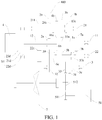
- a power drive system 100 according to embodiments of the present disclosure is described below in detail in combination with Fig. 1 to Fig. 7 , and the power drive system 100 is applicable to vehicles such as hybrid electric vehicles and provides sufficient power and electric energy for normal driving of the vehicle as a power system of the vehicle.
- the power drive system 100 mainly includes two major parts, one may be a power source, which may be an engine 4, an electric generator or the like, and the other may be a transmission (including a plurality of input shafts, a plurality of output shafts, gear pairs, etc.), which is used to implement a function of performing speed shifting on power output by the power source so as to satisfy a travelling requirement or a charging requirement or the like for the vehicle.
- a power source which may be an engine 4, an electric generator or the like
- a transmission including a plurality of input shafts, a plurality of output shafts, gear pairs, etc.
- the power drive system 100 may include an engine 4, a first electric generator 51, and a transmission, but is not limited thereto.
- the transmission mainly includes a plurality of input shafts (for example, a first input shaft 11, a second input shaft 12), a plurality of output shafts (for example, a first output shaft 21, a second output shaft 22), a reverse shaft 3, and related gears as well as gear shift elements (such as synchronizers) on various shafts.
- a plurality of input shafts for example, a first input shaft 11, a second input shaft 12
- a plurality of output shafts for example, a first output shaft 21, a second output shaft 22
- a reverse shaft 3 for example, a first output shaft 21, a second output shaft 22
- gear shift elements such as synchronizers
- the engine 4 When power transfer is performed between the engine 4 and the input shafts, the engine 4 is configured to be selectively engaged with at least one of the plurality of input shafts. In other words, when the engine 4 transmits power to the input shafts, the engine 4 can be selectively engaged with one of the plurality of input shafts so as to transmit power, or the engine 4 can also be selectively engaged with two or more of the plurality of input shafts simultaneously so as to transmit power.
- the plurality of shafts may include two input shafts, that is, a first input shaft 11 and a second input shaft 12, and the engine 4 can be selectively engaged with one of the first input shaft 11 and the second input shaft 12 so as to transmit power. Or, in particular, the engine 4 can also be engaged with the first input shaft 11 and the second input shaft 12 simultaneously so as to transmit power. Of course, it should be understood that the engine 4 may also be disengaged from the first input shaft 11 and the second input shaft 12 simultaneously.
- an engagement state of the engine 4 with the input shafts is related to specific working conditions of the power drive system 100, which will be described below in detail in combination with specific embodiments and will not be described here in detail.
- Transmission may be performed between the input shafts and the output shafts through gear pairs.
- each of the input shafts is provided with a gear driving gear
- each of the output shafts is provided with a gear driven gear
- a plurality of gear driven gears are meshed with a plurality of gear driving gears correspondingly, so as to constitute a plurality of gear pairs of different speed ratios.
- the power drive system 100 may have seven forward gear pairs, that is, a first gear pair, a second gear pair, a third gear pair, a fourth gear pair, a fifth gear pair, a sixth gear pair, and a seventh gear pair, and the power drive system 100 also has a reverse gear pair.
- the reverse shaft 3 and a reverse output gear 39 mainly have the following two arrangement forms.
- the reverse shaft 3 is sheathed with a first gear for the reverse shaft 31 which can be engaged with the reverse shaft 3, in other words, transmission may be performed between the reverse shaft 3 and the first gear for the reverse shaft 31.
- the reverse shaft 3 may also be provided with a first synchronizer for the reverse shaft 3c, which is used to be engaged with the reverse shaft 3 and the first gear for the reverse shaft 31.
- the first synchronizer for the reverse shaft 3c is used to be engaged with the reverse shaft 3 and the first gear for the reverse shaft 31, transmission is performed between the reverse shaft 3 and the first gear for the reverse shaft 31.
- the reverse output gear 39 is linked with the reverse shaft 3.
- the reverse shaft 3 may be fixedly provided with a second gear for the reverse shaft 32, which is meshed with the reverse output gear 39.
- the reverse output gear 39 may be fixed on one of the output shafts.
- the reverse output gear 39 is fixed on the second output shaft 22, so that the reverse output gear 39 may be arranged in a reasonable position, thus further reducing the volume of the power drive system 100.
- the above "linked” may be construed as a plurality of components (for example, two) moving in an associated manner, and taking two components linked as an example, one component moves while the other component also moves therewith.
- the feature that a gear is linked with a shaft may be construed as follows: when the gear rotates, the shaft linked therewith will also rotate, or when the shaft rotates, the gear linked therewith will also rotate.
- one shaft is linked with another shaft may be construed as follows: when one of the shafts rotates, the other shaft linked therewith will also rotate.
- the feature that a gear is linked with a gear may be construed as follows: when one of the gears rotates, the other gear linked therewith will also rotate.
- the first gear for the reverse shaft 31 may also be fixedly arranged on the reverse shaft 3, at this point, the reverse output gear 39 may be sheathed on one of the output shafts (for example, the second output shaft 22), and the reverse output gear 39 is configured to be engageable with the output shaft.
- the output shaft is also provided with a reverse-gear synchronizer (for example, a sixth-gear synchronizer 6c) that is used to be engaged with the reverse output gear 39, in other words, the reverse-gear synchronizer may be used to be engaged with the reverse output gear 39 and the output shaft, so that the output shaft and the reverse output gear 39 can rotate synchronously, and thus reverse-gear power can be output from the output shaft.
- a reverse-gear synchronizer for example, a sixth-gear synchronizer 6c
- the reverse output gear 39 shares the reverse-gear synchronizer with an adjacent gear driven gear (for example, a sixth-gear driven gear 6b). Therefore, this may decrease parts and components of the power drive system 100, enable the axial length of the power drive system 100 to be smaller and reduce the volume of the power drive system 100.
- the first gear for the reverse shaft 31 is meshed with one of the gear driving gears, for example, as shown in Fig. 1 , the first gear for the reverse shaft 31 is meshed with a first-gear driving gear 1a, so that the first gear for the reverse shaft 31 together with the first-gear driving gear 1a constitutes a reverse gear pair, and power may be transferred between the reverse shaft 3 and the input shafts.
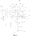
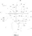
- the power drive system 100 only has the first electric generator 51 therein, and as shown in Fig. 3 to Fig. 7 , the power drive system 100 has the first electric generator 51 and a second electric generator 52 therein.
- first electric generator 51 There are a plurality of arrangement forms of the first electric generator 51, and specific arrangement forms of the first electric generator 51 are described below in detail in combination with Fig. 1 to Fig. 7 .
- the first electric generator 51 is linked with a differential power input gear 7 of the vehicle.
- power transfer may be performed between the first electric generator 51 and the differential power input gear 7 of the vehicle, when the first electric generator 51 is used as a motor, power of the first electric generator 51 may be transferred to a wheel through the differential power input gear 7 so as to drive the vehicle to move, and when the first electric generator 51 is used as a generator, energy transferred from the wheel may be transferred to the first electric generator 51 through the differential power input gear 7 so as to enable the first electric generator 51 to generate electricity.
- a plurality of output shafts are linked with the differential power input gear 7 of the vehicle, wherein each of the output shafts is provided with an output gear, and the output gear is meshed with the differential power input gear 7, for example, as shown in Fig. 1 to Fig. 7 , the plurality of output shafts includes a first output shaft 21 and a second output shaft 22, the first output shaft 21 is fixedly provided with a first-output-shaft output gear 211, the second output shaft 22 is fixedly provided with a second-output-shaft output gear 221, and the first-output-shaft output gear 211 and the second-output-shaft output gear 221 are meshed with the differential power input gear 7 of the vehicle respectively.
- power transferred from the engine 4 may be transferred to the differential power input gear 7 through the first-output-shaft output gear 211 on the first output shaft 21, the power transferred from the engine 4 may also be transferred to the differential power input gear 7 through the second-output-shaft output gear 221, or the power transferred from the engine 4 may also be transferred to the differential power input gear 7 through the output gears of the two output shafts mentioned above.
- the first electric generator 51 is linked with the reverse shaft 3, which is linked with the second output shaft 22 through the reverse output gear 39, so that the first electric generator 51 may be linked with the differential power input gear 7.
- the reverse shaft 3 is also fixedly provided with a first motor gear 33, and transmission is performed between the first electric generator 51 and the first motor gear 33 through a first transmission gear 511 and a second transmission gear 512, wherein the first transmission gear 511 is fixed on a generator shaft of the first electric generator 51, and the second transmission gear 512 is meshed between the first transmission gear 511 and the first motor gear 33.
- the first electric generator 51 is connected with the transmission directly through the first motor gear 33 by means of power coupling, and the power of the first electric generator 51 is output to the differential power input gear 7 through the transmission, that is, the first electric generator 51 is linked with the transmission directly through the first motor gear 33, and the first electric generator 51 is linked with the differential power input gear 7 indirectly through the transmission.
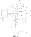
- the first electric generator 51 is configured to be linked with the differential power input gear 7 by being linked with the reverse output gear 39. Transmission is performed between the first electric generator 51 and the reverse output gear 39 through the first transmission gear 511 and the second transmission gear 512, wherein the first transmission gear 511 is fixed on the generator shaft of the first electric generator 51, and the second transmission gear 512 is meshed between the first transmission gear 511 and the reverse output gear 39.
- the first electric generator 51 is configured to be linked with the differential power input gear 7 directly through a plurality of gears, the first transmission gear 511, the second transmission gear 512, a third transmission gear 513, and a fourth transmission gear 514 are provided between the first electric generator 51 and the differential power input gear 7, the first transmission gear 511 is fixed on the generator shaft of the first electric generator 51, and the second transmission gear 512 is meshed between the first transmission gear 511 and the third transmission gear 513, wherein the third transmission gear 513 and the fourth transmission gear 514 are axially and fixedly arranged, and the fourth transmission gear 514 is meshed with the differential power input gear 7.
- the first electric generator 51 may also be linked with one of the plurality of output shafts, as shown in Fig. 6 , the first electric generator 51 is connected with the second output shaft 22, and as shown in Fig. 7 , the first electric generator 51 is connected with the first output shaft 21.
- the differential power input gear 7 may be linked with the first electric generator 51 through one of the plurality of output shafts.
- the second electric generator 52 is configured to be linked with the engine 4.
- the second electric generator 52 may be used to initiate the engine 4, or the second electric generator 52 may be used to drive the wheel to rotate.
- the engine 4 may drive the second electric generator 52 to generate electricity, and the energy transferred from the vehicle may drive, through the output shafts, the second electric generator 52 to generate electricity.
- the power drive system 100 may further include a dual clutch 2d, which has an input end 23d, a first output end 21d, and a second output end 22d, the input end 23d is selectively engaged with at least one of the first output end 21d and the second output end 22d, and the engine 4 is connected with the input end 23d, wherein the first output end 21d is connected with the first output shaft 21, and the second output end 22d is connected with the second output shaft 22, and wherein the input end 23d is provided with external teeth for the input end, with which the second electric generator 52 is linked. Since the input end 23d is connected with the engine 4, the second electric generator 52 may be linked with the engine 4 through the input end 23d. A generator shaft of the second electric generator 52 may be fixedly provided with a transmission gear connected with the external teeth for the input end.
- control strategy may be set adaptively according to a transmission mode required actually, so that switching may be performed between a plurality of modes as follows: the input end 23d is disengaged from the two output ends, and the input end 23d is engaged with at least one of the two output ends.
- the second input shaft 12 is sheathed on the first input shaft 11, which may enable the power drive system 100 to be compact in structure, effectively reduce the axial length of the power drive system 100, make the volume of the power drive system 100 be smaller, and facilitate the power drive system 100 being arranged on the vehicle.
- the first input shaft 11 may be provided with a first-gear driving gear 1a, a third and fifth-gear driving gear 35a, and a seventh-gear driving gear 7a
- the second input shaft 12 may be provided with a second-gear driving gear 2a and a fourth and sixth-gear driving gear 46a, and each gear driving gear rotates synchronously with a respective input shaft.
- the first output shaft 21 is provided with a first-gear driven gear 1b, a second-gear driven gear 2b, a third-gear driven gear 3b, and a fourth-gear driven gear 4b
- the second output shaft 22 is provided with a fifth-gear driven gear 5b, a sixth-gear driven gear 6b, and a seventh-gear driven gear 7b
- each gear driven gear is sheathed on a respective output shaft, that is, each gear driven gear can rotate differentially relative to the corresponding output shaft.
- the first-gear driven gear 1b is meshed with the first-gear driving gear 1a so as to constitute a first gear pair
- the second-gear driven gear 2b is meshed with the second-gear driving gear 2a so as to constitute a second gear pair
- the third-gear driven gear 3b is meshed with the third and fifth-gear driving gear 35a so as to constitute a third gear pair
- the fourth-gear driven gear 4b is meshed with the fourth and sixth-gear driving gear 46a so as to constitute a fourth gear pair
- the fifth-gear driven gear 5b is meshed with the third and fifth-gear driving gear 35a so as to constitute a fifth gear pair
- the sixth-gear driven gear 6b is meshed with the fourth and sixth-gear driving gear 46a so as to constitute a sixth gear pair
- the seventh-gear driven gear 7b is meshed with the seventh-gear driving gear 7a so as to constitute a seventh gear pair
- the first-gear driving gear 1a is meshed with the first
- the fourth gear pair and the sixth gear pair share the fourth and sixth-gear driving gear 46a, and the third gear pair and the fifth gear pair share the third and fifth-gear driving gear 35a, which may decrease two gear driving gears, so that the power drive system 100 may be more compact in structure and smaller in axial dimension.
- the power drive system 100 includes a first and third-gear synchronizer 13c, a second and fourth-gear synchronizer 24c, a fifth and seventh-gear synchronizer 57c, and a sixth-gear synchronizer 6c.
- the first and third-gear synchronizer 13c is arranged on the first output shaft 21 and located between the first-gear driven gear 1b and the third-gear driven gear 3b, and the first and third-gear synchronizer 13c may engage the first-gear driven gear 1b or the third-gear driven gear 3b with the first output shaft 21, so that the driven gear and the output shaft can rotate synchronously.
- the third-gear driven gear 3b may be engaged with the first output shaft 21, so that the third-gear driven gear 3b and the first output shaft 21 can rotate synchronously.
- the engagement sheath of the first and third-gear synchronizer 13c moves right, the first-gear driven gear 1b may be engaged with the first output shaft 21, so that the first-gear driven gear 1b and the first output shaft 21 can rotate synchronously.
- the second and fourth-gear synchronizer 24c is arranged on the first output shaft 21 and located between the second-gear driven gear 2b and the fourth-gear driven gear 4b, and the second and fourth-gear synchronizer 24c may engage the second-gear driven gear 2b or the fourth-gear driven gear 4b with the first output shaft 21, so that the driven gear and the output shaft can rotate synchronously.
- the second-gear driven gear 2b may be engaged with the first output shaft 21, so that the second-gear driven gear 2b and the first output shaft 21 rotate synchronously.
- the fourth-gear driven gear 4b may be engaged with the first output shaft 21, so that the fourth-gear driven gear 4b and the first output shaft 21 rotate synchronously.
- the fifth and seventh-gear synchronizer 57c is arranged on the second output shaft 22, the fifth and seventh-gear synchronizer 57c is located between the fifth-gear driven gear 5b and the seventh-gear driven gear 7b, and the fifth and seventh-gear synchronizer 57c is used to engage the fifth-gear driven gear 5b or the seventh-gear driven gear 7b with the second output shaft 22, for example, when an engagement sheath of the fifth and seventh-gear synchronizer 57c moves right, the seventh-gear driven gear 7b may be engaged with the second output shaft 22, so that the seventh-gear driven gear 7b and the second output shaft 22 rotate synchronously.
- the fifth-gear driven gear 5b may be engaged with the second output shaft 22, so that the fifth-gear driven gear 5b and the second output shaft 22 rotate synchronously.
- the sixth-gear synchronizer 6c is arranged on the second output shaft 22, the sixth-gear synchronizer 6c is located on one side of the sixth-gear driven gear 6b, for example, on the left side, and the sixth-gear synchronizer 6c is used to engage the sixth-gear driven gear 6b with the second output shaft 22, for example, when an engagement sheath of the sixth-gear synchronizer 6c moves right, the sixth-gear driven gear 6b may be engaged with the second output shaft 22, so that the sixth-gear driven gear 6b and the second output shaft 22 rotate synchronously.
- the reverse output gear 39 and the sixth-gear driven gear 6b are arranged adjacent to each other so as to share the sixth-gear synchronizer 6c, so that the sixth-gear synchronizer 6c constitutes the reverse-gear synchronizer.
- the reverse output gear 39 may be engaged, and when it moves right, the sixth-gear driven gear 6b may be engaged.
- distances of the second-gear driving gear 2a, the fourth and sixth-gear driving gear 46a, the third and fifth-gear driving gear 35a, the first-gear driving gear 1a, and the seventh-gear driving gear 7a from the engine 4 increase gradually. Therefore, gears are arranged more reasonably, the power drive system 100 is more compact, and radial and axial dimensions are relatively smaller.
- the first gear for the reverse shaft 31 is sheathed on the reverse shaft 3, and the reverse shaft 3 is provided with a first synchronizer for the reverse shaft 3c that is used to be engaged with the first gear for the reverse shaft 31, wherein the sixth-gear synchronizer 6c is located on the left side of the sixth-gear driven gear 6b, and the first synchronizer for the reverse shaft 3c is located on the right side of the first gear for the reverse shaft 31, so that the first synchronizer for the reverse shaft 3c and the sixth-gear synchronizer 6c may share the same shifting yoke mechanism, the sixth-gear synchronizer 6c is separated from the sixth-gear driven gear 6b when the shifting yoke mechanism drives the first synchronizer for the reverse shaft 3c to be engaged with the first gear for the reverse shaft 31, and the first synchronizer for the reverse shaft 3c is separated from the first gear for the reverse shaft 31 when the shifting yoke mechanism drives the sixth
- the shifting yoke mechanism drives an engagement sheath to move left
- the first synchronizer for the reverse shaft 3c is engaged with the first gear for the reverse shaft 31 and the sixth-gear synchronizer 6c is separated from the sixth-gear driven gear 6b
- the shifting yoke mechanism drives the engagement sheath to move right
- the sixth-gear synchronizer 6c is engaged with the sixth-gear driven gear 6b and the first synchronizer for the reverse shaft 3c is separated from the first gear for the reverse shaft 31. Therefore, one shifting yoke mechanism may be omitted for the power drive system 100, so that the power drive system 100 may be simple in structure and light in weight.
- An engine-only mode the transmission has seven forward gears, detailed description is made below by taking a first gear as an example, the input end 23d of the dual clutch 2d is connected with the first output end 21d, the first and third-gear synchronizer 13c is engaged with the first-gear driven gear 1b and the first output shaft 21, and power of the engine 4 is transferred to the wheel through the first-gear driving gear 1a, the first-gear driven gear 1b, the first and third-gear synchronizer 13c, the first output shaft 21, the first-output-shaft output gear 211, and the differential power input gear 7 in sequence so as to drive the vehicle to move.
- Other gear transfer processes are similar to that of the first gear, and will not be described here in detail. It should be explained that since the first electric generator 51 is linked with the reverse shaft 3, when the vehicle is in a reverse gear, the first electric generator 51 may be used as a generator so as to generate electricity.
- An electric-only mode the first electric generator 51 is used as a motor, and power of the first electric generator 51 is transferred to the wheel through the first transmission gear 511, the second transmission gear 512, the first motor gear 33, the reverse shaft 3, second gear for the reverse shaft 32, the reverse output gear 39, the second output shaft 22, the second-output-shaft output gear 221, and the differential power input gear 7 in sequence so as to drive the vehicle to move.
- a hybrid drive mode is a combination of the engine-only mode and the electric-only mode mentioned above, the power of the engine 4 is coupled with the power of the first electric generator 51 at the differential power input gear 7, and then the coupled power is transferred to the wheel to drive the vehicle to move.
- An energy recovery mode energy transferred from the wheel is transferred to the first electric generator 51 through the differential power input gear 7, the second-output-shaft output gear 221, the second output shaft 22, the reverse output gear 39, the second gear for the reverse shaft 32, the reverse shaft 3, the first motor gear 33, the second transmission gear 512, and the first transmission gear 511 in sequence, and at this point, the first electric generator 51 is used as a generator.
- An engine-only mode the transmission has seven forward gears, detailed description is made below by taking the first gear as an example, the input end 23d of the dual clutch 2d is connected with the first output end 21d, the first and third-gear synchronizer 13c is engaged with the first-gear driven gear 1b and the first output shaft 21, and the power of the engine 4 is transferred to the wheel through the first-gear driving gear 1a, the first-gear driven gear 1b, the first and third-gear synchronizer 13c, the first output shaft 21, the first-output-shaft output gear 211, and the differential power input gear 7 in sequence so as to drive the vehicle to move.
- Other gear transfer processes are similar to that of the first gear, and will not be described here in detail.
- the reverse output gear 39 is fixedly arranged on the second output shaft 22, so that when the transmission is in a fifth gear, a sixth gear and a seventh gear, part of the power of the engine 4 can be transferred to the first electric generator 51 through the second output shaft 22, the reverse output gear 39, the second transmission gear 512, and the first transmission gear 511, and at this point, the first electric generator 51 is used as a generator.
- An electric-only mode the first electric generator 51 is used as a motor, and the power of the first electric generator 51 is transferred to the wheel through the first transmission gear 511, the second transmission gear 512, the reverse output gear 39, the second output shaft 22, the second-output-shaft output gear 221, and the differential power input gear 7 in sequence so as to drive the vehicle to move.
- An energy recovery mode energy transferred from the wheel is transferred to the first electric generator 51 through the differential power input gear 7, the second-output-shaft output gear 221, the second output shaft 22, the reverse output gear 39, the second transmission gear 512, and the first transmission gear 511 in sequence, and at this point, the first electric generator 51 is used as a generator.
- a parking electricity generation mode the input end 23d of the dual clutch 2d is disengaged from the first output end 21d and the second output end 22d respectively, the power of the engine 4 is transferred to the second electric generator 52 through the input end 23d, and the second electric generator 52 is used as a generator.
- An engine-only mode the transmission has seven forward gears, detailed description is made below by taking the first gear as an example, the input end 23d of the dual clutch 2d is connected with the first output end 21d, the first and third-gear synchronizer 13c is engaged with the first-gear driven gear 1b and the first output shaft 21, and the power of the engine 4 is transferred to the wheel through the first-gear driving gear 1a, the first-gear driven gear 1b, the first and third-gear synchronizer 13c, the first output shaft 21, the first-output-shaft output gear 211, and the differential power input gear 7 in sequence so as to drive the vehicle to move.
- Other gear transfer processes are similar to that of the first gear, and will not be described here in detail.
- the reverse output gear 39 is fixedly arranged on the second output shaft 22, so that when the transmission is in the fifth gear, the sixth gear and the seventh gear, part of the power of the engine 4 can be transferred to the first electric generator 51 through the second output shaft 22, the reverse output gear 39, the second transmission gear 512, and the first transmission gear 511, and at this point, the first electric generator 51 is used as a generator. Additionally, another part of the power of the engine 4 may also drive the second electric generator 52 to generate electricity.
- Electric-only mode one the first electric generator 51 is used as a motor, and the power of the first electric generator 51 is transferred to the wheel through the first transmission gear 511, the second transmission gear 512, the reverse output gear 39, the second output shaft 22, the second-output-shaft output gear 221, and the differential power input gear 7 in sequence so as to drive the vehicle to move.
- Electric-only mode two the second electric generator 52 is used as a motor, detailed description is made below by taking the first gear as an example, the input end 23d of the dual clutch 2d is connected with the first output end 21d, the first and third-gear synchronizer 13c is engaged with the first-gear driven gear 1b and the first output shaft 21, and power of the second electric generator 52 is transferred to the wheel through the first-gear driving gear 1a, the first-gear driven gear 1b, the first and third-gear synchronizer 13c, the first output shaft 21, the first-output-shaft output gear 211, and the differential power input gear 7 in sequence so as to drive the vehicle to move.
- Other gear transfer processes are similar to that of the first gear, and will not be described here in detail. In this process, the engine 4 may be idle.
- Electric-only mode three the first electric generator 51 and the second electric generator 52 are used as motors simultaneously, and the power of the first electric generator 51 and the power of the second electric generator 52 are coupled at the differential power input gear 7 and then transferred to the wheel to drive the vehicle to move.
- An energy recovery mode energy transferred from the wheel is transferred to the first electric generator 51 through the differential power input gear 7, the second-output-shaft output gear 221, the second output shaft 22, the reverse output gear 39, the second transmission gear 512, and the first transmission gear 511 in sequence, and at this point, the first electric generator 51 is used as a generator.
- a parking electricity generation mode the input end 23d of the dual clutch 2d is disengaged from the first output end 21d and the second output end 22d respectively, the power of the engine 4 is transferred to the second electric generator 52 through the input end 23d, and the second electric generator 52 is used as a generator.
- An engine-only mode the transmission has seven forward gears, detailed description is made below by taking the first gear as an example, the input end 23d of the dual clutch 2d is connected with the first output end 21d, the first and third-gear synchronizer 13c is engaged with the first-gear driven gear 1b and the first output shaft 21, and the power of the engine 4 is transferred to the wheel through the first-gear driving gear 1a, the first-gear driven gear 1b, the first and third-gear synchronizer 13c, the first output shaft 21, the first-output-shaft output gear 211, and the differential power input gear 7 in sequence so as to drive the vehicle to move.
- Other gear transfer processes are similar to that of the first gear, and will not be described here in detail.
- the first electric generator 51 is linked with the reverse shaft 3, when the vehicle is in the reverse gear, the first electric generator 51 may be used as a generator so as to generate electricity. Additionally, part of the power of the engine 4 is used to drive the second electric generator 52 to generate electricity.
- Electric-only mode one the first electric generator 51 is used as a motor, and the power of the first electric generator 51 is transferred to the wheel through the first transmission gear 511, the second transmission gear 512, the first motor gear 33, the reverse shaft 3, second gear for the reverse shaft 32, the reverse output gear 39, the second output shaft 22, the second-output-shaft output gear 221, and the differential power input gear 7 in sequence so as to drive the vehicle to move.
- Electric-only mode two the second electric generator 52 is used as a motor, detailed description is made below by taking the first gear as an example, the input end 23d of the dual clutch 2d is connected with the first output end 21d, the first and third-gear synchronizer 13c is engaged with the first-gear driven gear 1b and the first output shaft 21, and the power of the second electric generator 52 is transferred to the wheel through the first-gear driving gear 1a, the first-gear driven gear 1b, the first and third-gear synchronizer 13c, the first output shaft 21, the first-output-shaft output gear 211, and the differential power input gear 7 in sequence so as to drive the vehicle to move.
- Other gear transfer processes are similar to that of the first gear, and will not be described here in detail.
- Electric-only mode three the first electric generator 51 and the second electric generator 52 are used as motors simultaneously, and the power of the first electric generator 51 and the power of the second electric generator 52 are coupled at the differential power input gear 7 and then transferred to the wheel to drive the vehicle to move.
- An energy recovery mode energy transferred from the wheel is transferred to the first electric generator 51 through the differential power input gear 7, the second-output-shaft output gear 221, the second output shaft 22, the reverse output gear 39, the second transmission gear 512, and the first transmission gear 511 in sequence, and at this point, the first electric generator 51 is used as a generator.
- a parking electricity generation mode the input end 23d of the dual clutch 2d is disengaged from the first output end 21d and the second output end 22d respectively, the power of the engine 4 is transferred to the second electric generator 52 through the input end 23d, and the second electric generator 52 is used as a generator.
- An engine-only mode the transmission has seven forward gears, detailed description is made below by taking the first gear as an example, the input end 23d of the dual clutch 2d is connected with the first output end 21d, the first and third-gear synchronizer 13c is engaged with the first-gear driven gear 1b and the first output shaft 21, and the power of the engine 4 is transferred to the wheel through the first-gear driving gear 1a, the first-gear driven gear 1b, the first and third-gear synchronizer 13c, the first output shaft 21, the first-output-shaft output gear 211, and the differential power input gear 7 in sequence so as to drive the vehicle to move.
- Other gear transfer processes are similar to that of the first gear, and will not be described here in detail. Additionally, part of the power of the engine 4 is used to drive the second electric generator 52 to generate electricity.
- Electric-only mode one the first electric generator 51 is used as a motor, and the power of the first electric generator 51 is transferred to the wheel through the first transmission gear 511, the second transmission gear 512, the third transmission gear 513, the fourth transmission gear 514, and the differential power input gear 7 in sequence so as to drive the vehicle to move.
- Electric-only mode two the second electric generator 52 is used as a motor, detailed description is made below by taking the first gear as an example, the input end 23d of the dual clutch 2d is connected with the first output end 21d, the first and third-gear synchronizer 13c is engaged with the first-gear driven gear 1b and the first output shaft 21, and the power of the second electric generator 52 is transferred to the wheel through the first-gear driving gear 1a, the first-gear driven gear 1b, the first and third-gear synchronizer 13c, the first output shaft 21, the first-output-shaft output gear 211, and the differential power input gear 7 in sequence so as to drive the vehicle to move.
- Other gear transfer processes are similar to that of the first gear, and will not be described here in detail.
- Electric-only mode three the first electric generator 51 and the second electric generator 52 are used as motors simultaneously, and the power of the first electric generator 51 and the power of the second electric generator 52 are coupled at the differential power input gear 7 and then transferred to the wheel to drive the vehicle to move.
- An energy recovery mode the power transferred from the wheel is transferred to the first electric generator 51 through the differential power input gear 7, the fourth transmission gear 514, the third transmission gear 513, the second transmission gear 512, and the first transmission gear 511 in sequence, and at this point, the first electric generator 51 is used as a generator.
- a parking electricity generation mode the input end 23d of the dual clutch 2d is disengaged from the first output end 21d and the second output end 22d respectively, the power of the engine 4 is transferred to the second electric generator 52 through the input end 23d, and the second electric generator 52 is used as a generator.
- An engine-only mode the transmission has seven forward gears, detailed description is made below by taking the first gear as an example, the input end 23d of the dual clutch 2d is connected with the first output end 21d, the first and third-gear synchronizer 13c is engaged with the first-gear driven gear 1b and the first output shaft 21, and the power of the engine 4 is transferred to the wheel through the first-gear driving gear 1a, the first-gear driven gear 1b, the first and third-gear synchronizer 13c, the first output shaft 21, the first-output-shaft output gear 211, and the differential power input gear 7 in sequence so as to drive the vehicle to move.
- Other gear transfer processes are similar to that of the first gear, and will not be described here in detail.
- part of the power of the engine 4 is used to drive the second electric generator 52 to generate electricity. It should be explained that since the first electric generator 51 is connected with the second output shaft 22, when gears of the transmission are the fifth gear, the sixth gear, and the seventh gear, the first electric generator 51 is used as a generator.
- Electric-only mode one the first electric generator 51 is used as a motor, and the power of the first electric generator 51 is transferred to the wheel through the second output shaft 22, the second-output-shaft output gear 221, and the differential power input gear 7 in sequence so as to drive the vehicle to move.
- Electric-only mode two the second electric generator 52 is used as a motor, detailed description is made below by taking the first gear as an example, the input end 23d of the dual clutch 2d is connected with the first output end 21d, the first and third-gear synchronizer 13c is engaged with the first-gear driven gear 1b and the first output shaft 21, and the power of the second electric generator 52 is transferred to the wheel through the first-gear driving gear 1a, the first-gear driven gear 1b, the first and third-gear synchronizer 13c, the first output shaft 21, the first-output-shaft output gear 211, and the differential power input gear 7 in sequence so as to drive the vehicle to move.
- Other gear transfer processes are similar to that of the first gear, and will not be described here in detail.
- Electric-only mode three the first electric generator 51 and the second electric generator 52 are used as motors simultaneously, and the power of the first electric generator 51 and the power of the second electric generator 52 are coupled at the differential power input gear 7 and then transferred to the wheel to drive the vehicle to move.
- An energy recovery mode the power transferred from the wheel is transferred to the first electric generator 51 through the differential power input gear 7, the second-output-shaft output gear 221, and the second output shaft 22 in sequence, and the first electric generator 51 is used as a generator.
- a parking electricity generation mode the input end 23d of the dual clutch 2d is disengaged from the first output end 21d and the second output end 22d respectively, the power of the engine 4 is transferred to the second electric generator 52 through the input end 23d, and the second electric generator 52 is used as a generator.
- An engine-only mode the transmission has seven forward gears, detailed description is made below by taking the first gear as an example, the input end 23d of the dual clutch 2d is connected with the first output end 21d, the first and third-gear synchronizer 13c is engaged with the first-gear driven gear 1b and the first output shaft 21, and the power of the engine 4 is transferred to the wheel through the first-gear driving gear 1a, the first-gear driven gear 1b, the first and third-gear synchronizer 13c, the first output shaft 21, the first-output-shaft output gear 211, and the differential power input gear 7 in sequence so as to drive the vehicle to move.
- Other gear transfer processes are similar to that of the first gear, and will not be described here in detail.
- part of the power of the engine 4 is used to drive the second electric generator 52 to generate electricity. It should be explained that since the first electric generator 51 is connected with the first output shaft 21, when the gears of the transmission are a first gear, a second gear, a third gear, and a fourth gear, the first electric generator 51 is used as a generator.
- Electric-only mode one the first electric generator 51 is used as a motor, and the power of the first electric generator 51 is transferred to the wheel through the first output shaft 21, the first-output-shaft output gear 211, and the differential power input gear 7 in sequence so as to drive the vehicle to move.
- Electric-only mode two the second electric generator 52 is used as a motor, detailed description is made below by taking the first gear as an example, the input end 23d of the dual clutch 2d is connected with the first output end 21d, the first and third-gear synchronizer 13c is engaged with the first-gear driven gear 1b and the first output shaft 21, and the power of the second electric generator 52 is transferred to the wheel through the first-gear driving gear 1a, the first-gear driven gear 1b, the first and third-gear synchronizer 13c, the first output shaft 21, the first-output-shaft output gear 211, and the differential power input gear 7 in sequence so as to drive the vehicle to move.
- Other gear transfer processes are similar to that of the first gear, and will not be described here in detail.
- Electric-only mode three the first electric generator 51 and the second electric generator 52 are used as motors simultaneously, and the power of the first electric generator 51 and the power of the second electric generator 52 are coupled at the differential power input gear 7 and then transferred to the wheel to drive the vehicle to move.
- An energy recovery mode the power transferred from the wheel is transferred to the first electric generator 51 through the differential power input gear 7, the first-output-shaft output gear 211, and the first output shaft 21 in sequence, and the first electric generator 51 is used as a generator.
- the first electric generator 51 since the first electric generator 51 is linked with the differential power input gear 7, the first electric generator 51 has very high transmission efficiency, and this may avoid the problem that an electric-only mode may be achieved only by complex gear shift and transmission chains in a transmission in a traditional power drive system 100, so that the electric-only mode has less components required for transmission, with reliable transmission processes and high transmission efficiency.
- a control logic of the engine 4 and a control logic of the first electric generator 51 are independent of each other, which may save the time and cost of development for manufacturers and avoid higher malfunction rates of the power drive system 100.
- a vehicle including the power drive system 100 as described above is further provided according to the embodiments of the present disclosure.
- other components of the vehicle according this embodiment of the present disclosure such as a driving system, a steering system, and a braking system are all existing technologies well known to a person of ordinary skill in the art, and therefore detailed descriptions of such known structures are omitted herein.
Landscapes
- Engineering & Computer Science (AREA)
- Mechanical Engineering (AREA)
- Chemical & Material Sciences (AREA)
- Combustion & Propulsion (AREA)
- Transportation (AREA)
- General Engineering & Computer Science (AREA)
- Structure Of Transmissions (AREA)
- Hybrid Electric Vehicles (AREA)
Abstract
Description
- The present disclosure relates to the technical field of automobiles, and in particular to a power drive system and a vehicle.
- With the increasing consumption of resources, the development and utilization of new energy vehicles has become an increasing tendency. As one of the new energy vehicles, a hybrid electric vehicle is driven by an engine and/or a motor, has a plurality of driving modes, and thus may improve transmission efficiency and fuel economy.
- However, in related technologies learned by the inventor, a transmission in the hybrid electric vehicle has a complex structure, less transmission modes, and lower transmission efficiency in an electric-only mode.
- The present disclosure aims at resolving one of technical problems in related technologies to some extent. To this end, the present disclosure provides a power drive system, which has high transmission efficiency in an electric-only mode.
- The present disclosure further provides a vehicle.
- The power drive system according to the present disclosure includes: an engine; a plurality of input shafts, the engine being configured to be selectively engaged with at least one of the plurality of input shafts each provided with a gear driving gear; a plurality of output shafts each provided with a gear driven gear, a plurality of gear driven gears being meshed with a plurality of gear driving gears correspondingly; a reverse shaft provided with a first gear for the reverse shaft, the first gear for the reverse shaft being meshed with one of the gear driving gears; a reverse output gear linked with the reverse shaft; and a first electric generator together with the plurality of output shafts linked with a differential power input gear of the vehicle respectively.
- In the power drive system according to the present disclosure, since the first electric generator is linked with the differential power input gear, the first electric generator has very high transmission efficiency, and this may avoid the problem that an electric-only mode may be achieved only by complex gear shift and transmission chains in a transmission in a traditional power drive system, so that the electric-only mode has less components required for transmission, with reliable transmission processes and high transmission efficiency. Additionally, for control logics, a control logic of the engine and a control logic of the first electric generator are independent of each other, which may save the time and cost of development for manufacturers and avoid higher malfunction rates of the power drive system.
- Additionally, the power drive system according to the present disclosure may also have the following distinguishing technical features.
- In some examples of the present disclosure, the first gear for the reverse shaft is sheathed on the reverse shaft.
- In some examples of the present disclosure, the power drive system further includes: a first synchronizer for the reverse shaft to be engaged with the reverse shaft and the first gear for the reverse shaft.
- In some examples of the present disclosure, the reverse output gear is fixed on one of the output shafts.
- In some examples of the present disclosure, the first gear for the reverse shaft is fixed on the reverse shaft.
- In some examples of the present disclosure, the reverse output gear is sheathed on one of the output shafts and the reverse output gear is configured to be engageable with the one of the output shafts.
- In some examples of the present disclosure, the power drive system further includes: a reverse-gear synchronizer to be engaged with the reverse output gear and the one of the output shafts.
- In some examples of the present disclosure, the reverse output gear shares the reverse-gear synchronizer with an adjacent gear driven gear.
- In some examples of the present disclosure, the reverse shaft is fixedly provided with a first motor gear, which is linked with the first electric generator.
- In some examples of the present disclosure, the first electric generator is configured to be linked with the differential power input gear by being linked with the reverse output gear.
- In some examples of the present disclosure, the reverse shaft is fixedly provided with a second gear for the reverse shaft, which is meshed with the reverse output gear.
- In some examples of the present disclosure, the power drive system further includes: a second electric generator configured to be linked with the engine.
- In some examples of the present disclosure, the power drive system further includes: a dual clutch having an input end, a first output end, and a second output end, the input end being selectively engaged with at least one of the first output end and the second output end, and the engine being connected with the input end.
- In some examples of the present disclosure, the input end is provided with external teeth for the input end, with which the second electric generator is linked.
- In some examples of the present disclosure, the plurality of input shafts includes: a first input shaft and a second input shaft sheathed on the first input shaft, the first input shaft being connected with the first output end, and the second input shaft being connected with the second output end; and the plurality of output shafts includes: a first output shaft and a second output shaft.
- In some examples of the present disclosure, the first input shaft is fixedly provided with a first-gear driving gear, a third and fifth-gear driving gear, and a seventh-gear driving gear, and the second input shaft is fixedly provided with a second-gear driving gear and a fourth and sixth-gear driving gear; the first output shaft is sheathed with a first-gear driven gear, a second-gear driven gear, a third-gear driven gear, and a fourth-gear driven gear; the second output shaft is sheathed with a fifth-gear driven gear, a sixth-gear driven gear, and a seventh-gear driven gear; and the first output shaft is provided with a first and third-gear synchronizer located between the first-gear driven gear and the third-gear driven gear, the first output shaft is also provided with a second and fourth-gear synchronizer located between the second-gear driven gear and the fourth-gear driven gear, the second output shaft is provided with a fifth and seventh-gear synchronizer located between the fifth-gear driven gear and the seventh-gear driven gear, and the second output shaft is also provided with a sixth-gear synchronizer located on one side of the sixth-gear driven gear.
- In some examples of the present disclosure, the first gear for the reverse shaft is meshed with the first-gear driving gear.
- In some examples of the present disclosure, the reverse output gear is fixedly arranged on the second output shaft; and the first gear for the reverse shaft is sheathed on the reverse shaft, and the reverse shaft is provided with the first synchronizer for the reverse shaft that is used to be engaged with the first gear for the reverse shaft, wherein the first synchronizer for the reverse shaft shares the same shifting yoke mechanism with the sixth-gear synchronizer, the sixth-gear synchronizer is separated from the sixth-gear driven gear when the shifting yoke mechanism drives the first synchronizer for the reverse shaft to be engaged with the first gear for the reverse shaft, and the first synchronizer for the reverse shaft is separated from the first gear for the reverse shaft when the shifting yoke mechanism drives the sixth-gear synchronizer to be engaged with the sixth-gear driven gear.
- In some examples of the present disclosure, the first gear for the reverse shaft is fixed on the reverse shaft; and the reverse output gear is sheathed on the second output shaft and adjacent to the sixth-gear driven gear, and the reverse output gear shares the sixth-gear synchronizer with the sixth-gear driven gear.
- In some examples of the present disclosure, the first output shaft is fixedly provided with a first-output-shaft output gear, the second output shaft is fixedly provided with a second-output-shaft output gear, and the first-output-shaft output gear and the second-output-shaft output gear are meshed with the differential power input gear of the vehicle respectively.
- The vehicle according to the present disclosure includes the described power drive system.
- The vehicle and the power drive system have the same beneficial effects, which will not be described here in detail.
-
-
Fig. 1 is a schematic diagram of a power drive system according to an embodiment of the present disclosure; -
Fig. 2 is a schematic diagram of a power drive system according to another embodiment of the present disclosure; -
Fig. 3 is a schematic diagram of a power drive system according to a further embodiment of the present disclosure; -
Fig. 4 is a schematic diagram of a power drive system according to still another embodiment of the present disclosure; -
Fig. 5 is a schematic diagram of a power drive system according to still another embodiment of the present disclosure; -
Fig. 6 is a schematic diagram of a power drive system according to still another embodiment of the present disclosure; and -
Fig. 7 is a schematic diagram of a power drive system according to still another embodiment of the present disclosure. - Embodiments of the present disclosure are described in detail below. Examples of the embodiments are illustrated in the accompanying drawings. The embodiments described below with reference to the accompanying drawings are exemplary, and are used for explaining rather than limiting the present disclosure.
- A
power drive system 100 according to embodiments of the present disclosure is described below in detail in combination withFig. 1 to Fig. 7 , and thepower drive system 100 is applicable to vehicles such as hybrid electric vehicles and provides sufficient power and electric energy for normal driving of the vehicle as a power system of the vehicle. - The
power drive system 100 according to the embodiments of the present disclosure mainly includes two major parts, one may be a power source, which may be anengine 4, an electric generator or the like, and the other may be a transmission (including a plurality of input shafts, a plurality of output shafts, gear pairs, etc.), which is used to implement a function of performing speed shifting on power output by the power source so as to satisfy a travelling requirement or a charging requirement or the like for the vehicle. - For example, in some embodiments, as shown in
Fig. 1 to Fig. 7 , thepower drive system 100 may include anengine 4, a firstelectric generator 51, and a transmission, but is not limited thereto. - As shown in combination with
Fig. 1 , in some embodiments, the transmission mainly includes a plurality of input shafts (for example, afirst input shaft 11, a second input shaft 12), a plurality of output shafts (for example, afirst output shaft 21, a second output shaft 22), areverse shaft 3, and related gears as well as gear shift elements (such as synchronizers) on various shafts. - When power transfer is performed between the
engine 4 and the input shafts, theengine 4 is configured to be selectively engaged with at least one of the plurality of input shafts. In other words, when theengine 4 transmits power to the input shafts, theengine 4 can be selectively engaged with one of the plurality of input shafts so as to transmit power, or theengine 4 can also be selectively engaged with two or more of the plurality of input shafts simultaneously so as to transmit power. - For example, in examples of
Fig. 1 to Fig. 7 , the plurality of shafts may include two input shafts, that is, afirst input shaft 11 and asecond input shaft 12, and theengine 4 can be selectively engaged with one of thefirst input shaft 11 and thesecond input shaft 12 so as to transmit power. Or, in particular, theengine 4 can also be engaged with thefirst input shaft 11 and thesecond input shaft 12 simultaneously so as to transmit power. Of course, it should be understood that theengine 4 may also be disengaged from thefirst input shaft 11 and thesecond input shaft 12 simultaneously. - For a person of ordinary skill in the art, an engagement state of the
engine 4 with the input shafts is related to specific working conditions of thepower drive system 100, which will be described below in detail in combination with specific embodiments and will not be described here in detail. - Transmission may be performed between the input shafts and the output shafts through gear pairs. For example, each of the input shafts is provided with a gear driving gear, each of the output shafts is provided with a gear driven gear, and a plurality of gear driven gears are meshed with a plurality of gear driving gears correspondingly, so as to constitute a plurality of gear pairs of different speed ratios.
- In some embodiments of the present disclosure, the
power drive system 100 may have seven forward gear pairs, that is, a first gear pair, a second gear pair, a third gear pair, a fourth gear pair, a fifth gear pair, a sixth gear pair, and a seventh gear pair, and thepower drive system 100 also has a reverse gear pair. - The
reverse shaft 3 and areverse output gear 39 mainly have the following two arrangement forms. As shown inFig. 1 to Fig. 4 , thereverse shaft 3 is sheathed with a first gear for thereverse shaft 31 which can be engaged with thereverse shaft 3, in other words, transmission may be performed between thereverse shaft 3 and the first gear for thereverse shaft 31. As shown inFig. 1 to Fig. 4 , thereverse shaft 3 may also be provided with a first synchronizer for thereverse shaft 3c, which is used to be engaged with thereverse shaft 3 and the first gear for thereverse shaft 31. When the first synchronizer for thereverse shaft 3c is used to be engaged with thereverse shaft 3 and the first gear for thereverse shaft 31, transmission is performed between thereverse shaft 3 and the first gear for thereverse shaft 31. Thereverse output gear 39 is linked with thereverse shaft 3. As shown inFig. 1 to Fig. 4 , thereverse shaft 3 may be fixedly provided with a second gear for thereverse shaft 32, which is meshed with thereverse output gear 39. Thereverse output gear 39 may be fixed on one of the output shafts. As shown inFig. 1 to Fig. 4 , thereverse output gear 39 is fixed on thesecond output shaft 22, so that thereverse output gear 39 may be arranged in a reasonable position, thus further reducing the volume of thepower drive system 100. - It should be explained that the above "linked" may be construed as a plurality of components (for example, two) moving in an associated manner, and taking two components linked as an example, one component moves while the other component also moves therewith. For example, in some embodiments of the present disclosure, the feature that a gear is linked with a shaft may be construed as follows: when the gear rotates, the shaft linked therewith will also rotate, or when the shaft rotates, the gear linked therewith will also rotate.
- In another example, the feature that one shaft is linked with another shaft may be construed as follows: when one of the shafts rotates, the other shaft linked therewith will also rotate.
- In still another example, the feature that a gear is linked with a gear may be construed as follows: when one of the gears rotates, the other gear linked therewith will also rotate.
- In the following description of the present disclosure related to "linked", it is construed as such, unless specially explained.
- As shown in
Fig. 5 to Fig. 7 , the first gear for thereverse shaft 31 may also be fixedly arranged on thereverse shaft 3, at this point, thereverse output gear 39 may be sheathed on one of the output shafts (for example, the second output shaft 22), and thereverse output gear 39 is configured to be engageable with the output shaft. Specifically, the output shaft is also provided with a reverse-gear synchronizer (for example, a sixth-gear synchronizer 6c) that is used to be engaged with thereverse output gear 39, in other words, the reverse-gear synchronizer may be used to be engaged with thereverse output gear 39 and the output shaft, so that the output shaft and thereverse output gear 39 can rotate synchronously, and thus reverse-gear power can be output from the output shaft. Preferably, as shown inFig. 5 to Fig. 7 , thereverse output gear 39 shares the reverse-gear synchronizer with an adjacent gear driven gear (for example, a sixth-gear drivengear 6b). Therefore, this may decrease parts and components of thepower drive system 100, enable the axial length of thepower drive system 100 to be smaller and reduce the volume of thepower drive system 100. - The first gear for the
reverse shaft 31 is meshed with one of the gear driving gears, for example, as shown inFig. 1 , the first gear for thereverse shaft 31 is meshed with a first-gear driving gear 1a, so that the first gear for thereverse shaft 31 together with the first-gear driving gear 1a constitutes a reverse gear pair, and power may be transferred between thereverse shaft 3 and the input shafts. - There are a plurality of electric generators and arrangement forms thereof, for example, as shown in
Fig. 1 andFig. 2 , thepower drive system 100 only has the firstelectric generator 51 therein, and as shown inFig. 3 to Fig. 7 , thepower drive system 100 has the firstelectric generator 51 and a secondelectric generator 52 therein. - There are a plurality of arrangement forms of the first
electric generator 51, and specific arrangement forms of the firstelectric generator 51 are described below in detail in combination withFig. 1 to Fig. 7 . - The first
electric generator 51 is linked with a differentialpower input gear 7 of the vehicle. In other words, power transfer may be performed between the firstelectric generator 51 and the differentialpower input gear 7 of the vehicle, when the firstelectric generator 51 is used as a motor, power of the firstelectric generator 51 may be transferred to a wheel through the differentialpower input gear 7 so as to drive the vehicle to move, and when the firstelectric generator 51 is used as a generator, energy transferred from the wheel may be transferred to the firstelectric generator 51 through the differentialpower input gear 7 so as to enable the firstelectric generator 51 to generate electricity. - A plurality of output shafts are linked with the differential
power input gear 7 of the vehicle, wherein each of the output shafts is provided with an output gear, and the output gear is meshed with the differentialpower input gear 7, for example, as shown inFig. 1 to Fig. 7 , the plurality of output shafts includes afirst output shaft 21 and asecond output shaft 22, thefirst output shaft 21 is fixedly provided with a first-output-shaft output gear 211, thesecond output shaft 22 is fixedly provided with a second-output-shaft output gear 221, and the first-output-shaft output gear 211 and the second-output-shaft output gear 221 are meshed with the differentialpower input gear 7 of the vehicle respectively. Therefore, power transferred from theengine 4 may be transferred to the differentialpower input gear 7 through the first-output-shaft output gear 211 on thefirst output shaft 21, the power transferred from theengine 4 may also be transferred to the differentialpower input gear 7 through the second-output-shaft output gear 221, or the power transferred from theengine 4 may also be transferred to the differentialpower input gear 7 through the output gears of the two output shafts mentioned above. - As shown in
Fig. 1 andFig. 4 , the firstelectric generator 51 is linked with thereverse shaft 3, which is linked with thesecond output shaft 22 through thereverse output gear 39, so that the firstelectric generator 51 may be linked with the differentialpower input gear 7. Specifically, thereverse shaft 3 is also fixedly provided with afirst motor gear 33, and transmission is performed between the firstelectric generator 51 and thefirst motor gear 33 through afirst transmission gear 511 and asecond transmission gear 512, wherein thefirst transmission gear 511 is fixed on a generator shaft of the firstelectric generator 51, and thesecond transmission gear 512 is meshed between thefirst transmission gear 511 and thefirst motor gear 33. - As such, the first
electric generator 51 is connected with the transmission directly through thefirst motor gear 33 by means of power coupling, and the power of the firstelectric generator 51 is output to the differentialpower input gear 7 through the transmission, that is, the firstelectric generator 51 is linked with the transmission directly through thefirst motor gear 33, and the firstelectric generator 51 is linked with the differentialpower input gear 7 indirectly through the transmission. - As shown in
Fig. 2 andFig. 3 , the firstelectric generator 51 is configured to be linked with the differentialpower input gear 7 by being linked with thereverse output gear 39. Transmission is performed between the firstelectric generator 51 and thereverse output gear 39 through thefirst transmission gear 511 and thesecond transmission gear 512, wherein thefirst transmission gear 511 is fixed on the generator shaft of the firstelectric generator 51, and thesecond transmission gear 512 is meshed between thefirst transmission gear 511 and thereverse output gear 39. - As shown in
Fig. 5 , the firstelectric generator 51 is configured to be linked with the differentialpower input gear 7 directly through a plurality of gears, thefirst transmission gear 511, thesecond transmission gear 512, athird transmission gear 513, and afourth transmission gear 514 are provided between the firstelectric generator 51 and the differentialpower input gear 7, thefirst transmission gear 511 is fixed on the generator shaft of the firstelectric generator 51, and thesecond transmission gear 512 is meshed between thefirst transmission gear 511 and thethird transmission gear 513, wherein thethird transmission gear 513 and thefourth transmission gear 514 are axially and fixedly arranged, and thefourth transmission gear 514 is meshed with the differentialpower input gear 7. - As shown in
Fig. 6 andFig. 7 , the firstelectric generator 51 may also be linked with one of the plurality of output shafts, as shown inFig. 6 , the firstelectric generator 51 is connected with thesecond output shaft 22, and as shown inFig. 7 , the firstelectric generator 51 is connected with thefirst output shaft 21. As such, the differentialpower input gear 7 may be linked with the firstelectric generator 51 through one of the plurality of output shafts. - Arrangement forms of the second
electric generator 52 are described below in detail in combination withFig. 3 to Fig. 7 , and as shown inFig. 3 to Fig. 7 , the secondelectric generator 52 is configured to be linked with theengine 4. When the secondelectric generator 52 is used as a motor, the secondelectric generator 52 may be used to initiate theengine 4, or the secondelectric generator 52 may be used to drive the wheel to rotate. When the secondelectric generator 52 is used as a generator, theengine 4 may drive the secondelectric generator 52 to generate electricity, and the energy transferred from the vehicle may drive, through the output shafts, the secondelectric generator 52 to generate electricity. - The
power drive system 100 may further include a dual clutch 2d, which has aninput end 23d, afirst output end 21d, and asecond output end 22d, theinput end 23d is selectively engaged with at least one of thefirst output end 21d and thesecond output end 22d, and theengine 4 is connected with theinput end 23d, wherein thefirst output end 21d is connected with thefirst output shaft 21, and thesecond output end 22d is connected with thesecond output shaft 22, and wherein theinput end 23d is provided with external teeth for the input end, with which the secondelectric generator 52 is linked. Since theinput end 23d is connected with theengine 4, the secondelectric generator 52 may be linked with theengine 4 through theinput end 23d. A generator shaft of the secondelectric generator 52 may be fixedly provided with a transmission gear connected with the external teeth for the input end. - It should be understood that specific engagement states of the dual clutch 2d are affected by a control strategy, and for a person skilled in the art, the control strategy may be set adaptively according to a transmission mode required actually, so that switching may be performed between a plurality of modes as follows: the
input end 23d is disengaged from the two output ends, and theinput end 23d is engaged with at least one of the two output ends. - As shown in
Fig. 1 to Fig. 7 , thesecond input shaft 12 is sheathed on thefirst input shaft 11, which may enable thepower drive system 100 to be compact in structure, effectively reduce the axial length of thepower drive system 100, make the volume of thepower drive system 100 be smaller, and facilitate thepower drive system 100 being arranged on the vehicle. - As shown in
Fig. 1 to Fig. 7 , thefirst input shaft 11 may be provided with a first-gear driving gear 1a, a third and fifth-gear driving gear 35a, and a seventh-gear driving gear 7a, thesecond input shaft 12 may be provided with a second-gear driving gear 2a and a fourth and sixth-gear driving gear 46a, and each gear driving gear rotates synchronously with a respective input shaft. - Correspondingly, as shown in
Fig. 1 to Fig. 7 , thefirst output shaft 21 is provided with a first-gear drivengear 1b, a second-gear drivengear 2b, a third-gear drivengear 3b, and a fourth-gear drivengear 4b, thesecond output shaft 22 is provided with a fifth-gear drivengear 5b, a sixth-gear drivengear 6b, and a seventh-gear drivengear 7b, and each gear driven gear is sheathed on a respective output shaft, that is, each gear driven gear can rotate differentially relative to the corresponding output shaft. - The first-gear driven
gear 1b is meshed with the first-gear driving gear 1a so as to constitute a first gear pair, the second-gear drivengear 2b is meshed with the second-gear driving gear 2a so as to constitute a second gear pair, the third-gear drivengear 3b is meshed with the third and fifth-gear driving gear 35a so as to constitute a third gear pair, the fourth-gear drivengear 4b is meshed with the fourth and sixth-gear driving gear 46a so as to constitute a fourth gear pair, the fifth-gear drivengear 5b is meshed with the third and fifth-gear driving gear 35a so as to constitute a fifth gear pair, the sixth-gear drivengear 6b is meshed with the fourth and sixth-gear driving gear 46a so as to constitute a sixth gear pair, the seventh-gear drivengear 7b is meshed with the seventh-gear driving gear 7a so as to constitute a seventh gear pair, and the first-gear driving gear 1a is meshed with the first gear for thereverse shaft 31 so as to constitute a reverse gear pair. - The fourth gear pair and the sixth gear pair share the fourth and sixth-
gear driving gear 46a, and the third gear pair and the fifth gear pair share the third and fifth-gear driving gear 35a, which may decrease two gear driving gears, so that thepower drive system 100 may be more compact in structure and smaller in axial dimension. - Since there is a sheathed structure between the driven gears and the output shafts, a synchronizer needs to be provided to synchronize corresponding driven gears and output shafts, so as to achieve the output of power.
- In some embodiments, as shown in combination with
Fig. 1 to Fig. 7 , thepower drive system 100 includes a first and third-gear synchronizer 13c, a second and fourth-gear synchronizer 24c, a fifth and seventh-gear synchronizer 57c, and a sixth-gear synchronizer 6c. - As shown in
Fig. 1 , the first and third-gear synchronizer 13c is arranged on thefirst output shaft 21 and located between the first-gear drivengear 1b and the third-gear drivengear 3b, and the first and third-gear synchronizer 13c may engage the first-gear drivengear 1b or the third-gear drivengear 3b with thefirst output shaft 21, so that the driven gear and the output shaft can rotate synchronously. - For example, as shown in combination with
Fig. 1 , when an engagement sheath of the first and third-gear synchronizer 13c moves left, the third-gear drivengear 3b may be engaged with thefirst output shaft 21, so that the third-gear drivengear 3b and thefirst output shaft 21 can rotate synchronously. When the engagement sheath of the first and third-gear synchronizer 13c moves right, the first-gear drivengear 1b may be engaged with thefirst output shaft 21, so that the first-gear drivengear 1b and thefirst output shaft 21 can rotate synchronously. - As shown in
Fig. 1 , similarly, the second and fourth-gear synchronizer 24c is arranged on thefirst output shaft 21 and located between the second-gear drivengear 2b and the fourth-gear drivengear 4b, and the second and fourth-gear synchronizer 24c may engage the second-gear drivengear 2b or the fourth-gear drivengear 4b with thefirst output shaft 21, so that the driven gear and the output shaft can rotate synchronously. - For example, as shown in combination with
Fig. 1 , when an engagement sheath of the second and fourth-gear synchronizer 24c moves left, the second-gear drivengear 2b may be engaged with thefirst output shaft 21, so that the second-gear drivengear 2b and thefirst output shaft 21 rotate synchronously. When the engagement sheath of the second and fourth-gear synchronizer 24c moves right, the fourth-gear drivengear 4b may be engaged with thefirst output shaft 21, so that the fourth-gear drivengear 4b and thefirst output shaft 21 rotate synchronously. - As shown in
Fig. 1 , similarly, the fifth and seventh-gear synchronizer 57c is arranged on thesecond output shaft 22, the fifth and seventh-gear synchronizer 57c is located between the fifth-gear drivengear 5b and the seventh-gear drivengear 7b, and the fifth and seventh-gear synchronizer 57c is used to engage the fifth-gear drivengear 5b or the seventh-gear drivengear 7b with thesecond output shaft 22, for example, when an engagement sheath of the fifth and seventh-gear synchronizer 57c moves right, the seventh-gear drivengear 7b may be engaged with thesecond output shaft 22, so that the seventh-gear drivengear 7b and thesecond output shaft 22 rotate synchronously. In another example, when the engagement sheath of the fifth and seventh-gear synchronizer 57c moves left, the fifth-gear drivengear 5b may be engaged with thesecond output shaft 22, so that the fifth-gear drivengear 5b and thesecond output shaft 22 rotate synchronously. - As shown in
Fig. 1 , similarly, the sixth-gear synchronizer 6c is arranged on thesecond output shaft 22, the sixth-gear synchronizer 6c is located on one side of the sixth-gear drivengear 6b, for example, on the left side, and the sixth-gear synchronizer 6c is used to engage the sixth-gear drivengear 6b with thesecond output shaft 22, for example, when an engagement sheath of the sixth-gear synchronizer 6c moves right, the sixth-gear drivengear 6b may be engaged with thesecond output shaft 22, so that the sixth-gear drivengear 6b and thesecond output shaft 22 rotate synchronously. - As shown in
Fig. 5 to Fig. 7 , thereverse output gear 39 and the sixth-gear drivengear 6b are arranged adjacent to each other so as to share the sixth-gear synchronizer 6c, so that the sixth-gear synchronizer 6c constitutes the reverse-gear synchronizer. As shown in combination withFig. 5 to Fig. 7 , when the engagement sheath of the sixth-gear synchronizer 6c moves left, thereverse output gear 39 may be engaged, and when it moves right, the sixth-gear drivengear 6b may be engaged. - In some embodiments, as shown in
Fig. 1 , distances of the second-gear driving gear 2a, the fourth and sixth-gear driving gear 46a, the third and fifth-gear driving gear 35a, the first-gear driving gear 1a, and the seventh-gear driving gear 7a from theengine 4 increase gradually. Therefore, gears are arranged more reasonably, thepower drive system 100 is more compact, and radial and axial dimensions are relatively smaller. - For a
power drive system 100 with thereverse output gear 39 fixedly arranged on thesecond output shaft 22, the first gear for thereverse shaft 31 is sheathed on thereverse shaft 3, and thereverse shaft 3 is provided with a first synchronizer for thereverse shaft 3c that is used to be engaged with the first gear for thereverse shaft 31, wherein the sixth-gear synchronizer 6c is located on the left side of the sixth-gear drivengear 6b, and the first synchronizer for thereverse shaft 3c is located on the right side of the first gear for thereverse shaft 31, so that the first synchronizer for thereverse shaft 3c and the sixth-gear synchronizer 6c may share the same shifting yoke mechanism, the sixth-gear synchronizer 6c is separated from the sixth-gear drivengear 6b when the shifting yoke mechanism drives the first synchronizer for thereverse shaft 3c to be engaged with the first gear for thereverse shaft 31, and the first synchronizer for thereverse shaft 3c is separated from the first gear for thereverse shaft 31 when the shifting yoke mechanism drives the sixth-gear synchronizer 6c to be engaged with the sixth-gear drivengear 6b. Specifically, when the shifting yoke mechanism drives an engagement sheath to move left, the first synchronizer for thereverse shaft 3c is engaged with the first gear for thereverse shaft 31 and the sixth-gear synchronizer 6c is separated from the sixth-gear drivengear 6b, and when the shifting yoke mechanism drives the engagement sheath to move right, the sixth-gear synchronizer 6c is engaged with the sixth-gear drivengear 6b and the first synchronizer for thereverse shaft 3c is separated from the first gear for thereverse shaft 31. Therefore, one shifting yoke mechanism may be omitted for thepower drive system 100, so that thepower drive system 100 may be simple in structure and light in weight. - Working modes of the
power drive system 100 according to the embodiments of the present disclosure are described below in detail by taking thepower drive system 100 shown inFig. 1 as an example. - An engine-only mode: the transmission has seven forward gears, detailed description is made below by taking a first gear as an example, the
input end 23d of the dual clutch 2d is connected with thefirst output end 21d, the first and third-gear synchronizer 13c is engaged with the first-gear drivengear 1b and thefirst output shaft 21, and power of theengine 4 is transferred to the wheel through the first-gear driving gear 1a, the first-gear drivengear 1b, the first and third-gear synchronizer 13c, thefirst output shaft 21, the first-output-shaft output gear 211, and the differentialpower input gear 7 in sequence so as to drive the vehicle to move. Other gear transfer processes are similar to that of the first gear, and will not be described here in detail. It should be explained that since the firstelectric generator 51 is linked with thereverse shaft 3, when the vehicle is in a reverse gear, the firstelectric generator 51 may be used as a generator so as to generate electricity. - An electric-only mode: the first
electric generator 51 is used as a motor, and power of the firstelectric generator 51 is transferred to the wheel through thefirst transmission gear 511, thesecond transmission gear 512, thefirst motor gear 33, thereverse shaft 3, second gear for thereverse shaft 32, thereverse output gear 39, thesecond output shaft 22, the second-output-shaft output gear 221, and the differentialpower input gear 7 in sequence so as to drive the vehicle to move. - A hybrid drive mode is a combination of the engine-only mode and the electric-only mode mentioned above, the power of the
engine 4 is coupled with the power of the firstelectric generator 51 at the differentialpower input gear 7, and then the coupled power is transferred to the wheel to drive the vehicle to move. - An energy recovery mode: energy transferred from the wheel is transferred to the first
electric generator 51 through the differentialpower input gear 7, the second-output-shaft output gear 221, thesecond output shaft 22, thereverse output gear 39, the second gear for thereverse shaft 32, thereverse shaft 3, thefirst motor gear 33, thesecond transmission gear 512, and thefirst transmission gear 511 in sequence, and at this point, the firstelectric generator 51 is used as a generator. - Working modes of the
power drive system 100 according to the embodiments of the present disclosure are described below in detail by taking thepower drive system 100 shown inFig. 2 as an example. - An engine-only mode: the transmission has seven forward gears, detailed description is made below by taking the first gear as an example, the
input end 23d of the dual clutch 2d is connected with thefirst output end 21d, the first and third-gear synchronizer 13c is engaged with the first-gear drivengear 1b and thefirst output shaft 21, and the power of theengine 4 is transferred to the wheel through the first-gear driving gear 1a, the first-gear drivengear 1b, the first and third-gear synchronizer 13c, thefirst output shaft 21, the first-output-shaft output gear 211, and the differentialpower input gear 7 in sequence so as to drive the vehicle to move. Other gear transfer processes are similar to that of the first gear, and will not be described here in detail. - The
reverse output gear 39 is fixedly arranged on thesecond output shaft 22, so that when the transmission is in a fifth gear, a sixth gear and a seventh gear, part of the power of theengine 4 can be transferred to the firstelectric generator 51 through thesecond output shaft 22, thereverse output gear 39, thesecond transmission gear 512, and thefirst transmission gear 511, and at this point, the firstelectric generator 51 is used as a generator. - An electric-only mode: the first
electric generator 51 is used as a motor, and the power of the firstelectric generator 51 is transferred to the wheel through thefirst transmission gear 511, thesecond transmission gear 512, thereverse output gear 39, thesecond output shaft 22, the second-output-shaft output gear 221, and the differentialpower input gear 7 in sequence so as to drive the vehicle to move. - An energy recovery mode: energy transferred from the wheel is transferred to the first
electric generator 51 through the differentialpower input gear 7, the second-output-shaft output gear 221, thesecond output shaft 22, thereverse output gear 39, thesecond transmission gear 512, and thefirst transmission gear 511 in sequence, and at this point, the firstelectric generator 51 is used as a generator. - Working modes of the
power drive system 100 according to the embodiments of the present disclosure are described below in detail by taking thepower drive system 100 shown inFig. 3 as an example. - A parking electricity generation mode: the
input end 23d of the dual clutch 2d is disengaged from thefirst output end 21d and thesecond output end 22d respectively, the power of theengine 4 is transferred to the secondelectric generator 52 through theinput end 23d, and the secondelectric generator 52 is used as a generator. - An engine-only mode: the transmission has seven forward gears, detailed description is made below by taking the first gear as an example, the
input end 23d of the dual clutch 2d is connected with thefirst output end 21d, the first and third-gear synchronizer 13c is engaged with the first-gear drivengear 1b and thefirst output shaft 21, and the power of theengine 4 is transferred to the wheel through the first-gear driving gear 1a, the first-gear drivengear 1b, the first and third-gear synchronizer 13c, thefirst output shaft 21, the first-output-shaft output gear 211, and the differentialpower input gear 7 in sequence so as to drive the vehicle to move. Other gear transfer processes are similar to that of the first gear, and will not be described here in detail. - The
reverse output gear 39 is fixedly arranged on thesecond output shaft 22, so that when the transmission is in the fifth gear, the sixth gear and the seventh gear, part of the power of theengine 4 can be transferred to the firstelectric generator 51 through thesecond output shaft 22, thereverse output gear 39, thesecond transmission gear 512, and thefirst transmission gear 511, and at this point, the firstelectric generator 51 is used as a generator. Additionally, another part of the power of theengine 4 may also drive the secondelectric generator 52 to generate electricity. - Electric-only mode one: the first
electric generator 51 is used as a motor, and the power of the firstelectric generator 51 is transferred to the wheel through thefirst transmission gear 511, thesecond transmission gear 512, thereverse output gear 39, thesecond output shaft 22, the second-output-shaft output gear 221, and the differentialpower input gear 7 in sequence so as to drive the vehicle to move. - Electric-only mode two: the second
electric generator 52 is used as a motor, detailed description is made below by taking the first gear as an example, theinput end 23d of the dual clutch 2d is connected with thefirst output end 21d, the first and third-gear synchronizer 13c is engaged with the first-gear drivengear 1b and thefirst output shaft 21, and power of the secondelectric generator 52 is transferred to the wheel through the first-gear driving gear 1a, the first-gear drivengear 1b, the first and third-gear synchronizer 13c, thefirst output shaft 21, the first-output-shaft output gear 211, and the differentialpower input gear 7 in sequence so as to drive the vehicle to move. Other gear transfer processes are similar to that of the first gear, and will not be described here in detail. In this process, theengine 4 may be idle. - Electric-only mode three: the first
electric generator 51 and the secondelectric generator 52 are used as motors simultaneously, and the power of the firstelectric generator 51 and the power of the secondelectric generator 52 are coupled at the differentialpower input gear 7 and then transferred to the wheel to drive the vehicle to move. - An energy recovery mode: energy transferred from the wheel is transferred to the first
electric generator 51 through the differentialpower input gear 7, the second-output-shaft output gear 221, thesecond output shaft 22, thereverse output gear 39, thesecond transmission gear 512, and thefirst transmission gear 511 in sequence, and at this point, the firstelectric generator 51 is used as a generator. - Working modes of the
power drive system 100 according to the embodiments of the present disclosure are described below in detail by taking thepower drive system 100 shown inFig. 4 as an example. - A parking electricity generation mode: the
input end 23d of the dual clutch 2d is disengaged from thefirst output end 21d and thesecond output end 22d respectively, the power of theengine 4 is transferred to the secondelectric generator 52 through theinput end 23d, and the secondelectric generator 52 is used as a generator. - An engine-only mode: the transmission has seven forward gears, detailed description is made below by taking the first gear as an example, the
input end 23d of the dual clutch 2d is connected with thefirst output end 21d, the first and third-gear synchronizer 13c is engaged with the first-gear drivengear 1b and thefirst output shaft 21, and the power of theengine 4 is transferred to the wheel through the first-gear driving gear 1a, the first-gear drivengear 1b, the first and third-gear synchronizer 13c, thefirst output shaft 21, the first-output-shaft output gear 211, and the differentialpower input gear 7 in sequence so as to drive the vehicle to move. Other gear transfer processes are similar to that of the first gear, and will not be described here in detail. It should be explained that since the firstelectric generator 51 is linked with thereverse shaft 3, when the vehicle is in the reverse gear, the firstelectric generator 51 may be used as a generator so as to generate electricity. Additionally, part of the power of theengine 4 is used to drive the secondelectric generator 52 to generate electricity. - Electric-only mode one: the first
electric generator 51 is used as a motor, and the power of the firstelectric generator 51 is transferred to the wheel through thefirst transmission gear 511, thesecond transmission gear 512, thefirst motor gear 33, thereverse shaft 3, second gear for thereverse shaft 32, thereverse output gear 39, thesecond output shaft 22, the second-output-shaft output gear 221, and the differentialpower input gear 7 in sequence so as to drive the vehicle to move. - Electric-only mode two: the second
electric generator 52 is used as a motor, detailed description is made below by taking the first gear as an example, theinput end 23d of the dual clutch 2d is connected with thefirst output end 21d, the first and third-gear synchronizer 13c is engaged with the first-gear drivengear 1b and thefirst output shaft 21, and the power of the secondelectric generator 52 is transferred to the wheel through the first-gear driving gear 1a, the first-gear drivengear 1b, the first and third-gear synchronizer 13c, thefirst output shaft 21, the first-output-shaft output gear 211, and the differentialpower input gear 7 in sequence so as to drive the vehicle to move. Other gear transfer processes are similar to that of the first gear, and will not be described here in detail. - Electric-only mode three: the first
electric generator 51 and the secondelectric generator 52 are used as motors simultaneously, and the power of the firstelectric generator 51 and the power of the secondelectric generator 52 are coupled at the differentialpower input gear 7 and then transferred to the wheel to drive the vehicle to move. - An energy recovery mode: energy transferred from the wheel is transferred to the first
electric generator 51 through the differentialpower input gear 7, the second-output-shaft output gear 221, thesecond output shaft 22, thereverse output gear 39, thesecond transmission gear 512, and thefirst transmission gear 511 in sequence, and at this point, the firstelectric generator 51 is used as a generator. - Working modes of the
power drive system 100 according to the embodiments of the present disclosure are described below in detail by taking thepower drive system 100 shown inFig. 5 as an example. - A parking electricity generation mode: the
input end 23d of the dual clutch 2d is disengaged from thefirst output end 21d and thesecond output end 22d respectively, the power of theengine 4 is transferred to the secondelectric generator 52 through theinput end 23d, and the secondelectric generator 52 is used as a generator. - An engine-only mode: the transmission has seven forward gears, detailed description is made below by taking the first gear as an example, the
input end 23d of the dual clutch 2d is connected with thefirst output end 21d, the first and third-gear synchronizer 13c is engaged with the first-gear drivengear 1b and thefirst output shaft 21, and the power of theengine 4 is transferred to the wheel through the first-gear driving gear 1a, the first-gear drivengear 1b, the first and third-gear synchronizer 13c, thefirst output shaft 21, the first-output-shaft output gear 211, and the differentialpower input gear 7 in sequence so as to drive the vehicle to move. Other gear transfer processes are similar to that of the first gear, and will not be described here in detail. Additionally, part of the power of theengine 4 is used to drive the secondelectric generator 52 to generate electricity. - Electric-only mode one: the first
electric generator 51 is used as a motor, and the power of the firstelectric generator 51 is transferred to the wheel through thefirst transmission gear 511, thesecond transmission gear 512, thethird transmission gear 513, thefourth transmission gear 514, and the differentialpower input gear 7 in sequence so as to drive the vehicle to move. - Electric-only mode two: the second
electric generator 52 is used as a motor, detailed description is made below by taking the first gear as an example, theinput end 23d of the dual clutch 2d is connected with thefirst output end 21d, the first and third-gear synchronizer 13c is engaged with the first-gear drivengear 1b and thefirst output shaft 21, and the power of the secondelectric generator 52 is transferred to the wheel through the first-gear driving gear 1a, the first-gear drivengear 1b, the first and third-gear synchronizer 13c, thefirst output shaft 21, the first-output-shaft output gear 211, and the differentialpower input gear 7 in sequence so as to drive the vehicle to move. Other gear transfer processes are similar to that of the first gear, and will not be described here in detail. - Electric-only mode three: the first
electric generator 51 and the secondelectric generator 52 are used as motors simultaneously, and the power of the firstelectric generator 51 and the power of the secondelectric generator 52 are coupled at the differentialpower input gear 7 and then transferred to the wheel to drive the vehicle to move. - An energy recovery mode: the power transferred from the wheel is transferred to the first
electric generator 51 through the differentialpower input gear 7, thefourth transmission gear 514, thethird transmission gear 513, thesecond transmission gear 512, and thefirst transmission gear 511 in sequence, and at this point, the firstelectric generator 51 is used as a generator. - Working modes of the
power drive system 100 according to the embodiments of the present disclosure are described below in detail by taking thepower drive system 100 shown inFig. 6 as an example. - A parking electricity generation mode: the
input end 23d of the dual clutch 2d is disengaged from thefirst output end 21d and thesecond output end 22d respectively, the power of theengine 4 is transferred to the secondelectric generator 52 through theinput end 23d, and the secondelectric generator 52 is used as a generator. - An engine-only mode: the transmission has seven forward gears, detailed description is made below by taking the first gear as an example, the
input end 23d of the dual clutch 2d is connected with thefirst output end 21d, the first and third-gear synchronizer 13c is engaged with the first-gear drivengear 1b and thefirst output shaft 21, and the power of theengine 4 is transferred to the wheel through the first-gear driving gear 1a, the first-gear drivengear 1b, the first and third-gear synchronizer 13c, thefirst output shaft 21, the first-output-shaft output gear 211, and the differentialpower input gear 7 in sequence so as to drive the vehicle to move. Other gear transfer processes are similar to that of the first gear, and will not be described here in detail. Additionally, part of the power of theengine 4 is used to drive the secondelectric generator 52 to generate electricity. It should be explained that since the firstelectric generator 51 is connected with thesecond output shaft 22, when gears of the transmission are the fifth gear, the sixth gear, and the seventh gear, the firstelectric generator 51 is used as a generator. - Electric-only mode one: the first
electric generator 51 is used as a motor, and the power of the firstelectric generator 51 is transferred to the wheel through thesecond output shaft 22, the second-output-shaft output gear 221, and the differentialpower input gear 7 in sequence so as to drive the vehicle to move. - Electric-only mode two: the second
electric generator 52 is used as a motor, detailed description is made below by taking the first gear as an example, theinput end 23d of the dual clutch 2d is connected with thefirst output end 21d, the first and third-gear synchronizer 13c is engaged with the first-gear drivengear 1b and thefirst output shaft 21, and the power of the secondelectric generator 52 is transferred to the wheel through the first-gear driving gear 1a, the first-gear drivengear 1b, the first and third-gear synchronizer 13c, thefirst output shaft 21, the first-output-shaft output gear 211, and the differentialpower input gear 7 in sequence so as to drive the vehicle to move. Other gear transfer processes are similar to that of the first gear, and will not be described here in detail. - Electric-only mode three: the first
electric generator 51 and the secondelectric generator 52 are used as motors simultaneously, and the power of the firstelectric generator 51 and the power of the secondelectric generator 52 are coupled at the differentialpower input gear 7 and then transferred to the wheel to drive the vehicle to move. - An energy recovery mode: the power transferred from the wheel is transferred to the first
electric generator 51 through the differentialpower input gear 7, the second-output-shaft output gear 221, and thesecond output shaft 22 in sequence, and the firstelectric generator 51 is used as a generator. - Working modes of the
power drive system 100 according to the embodiments of the present disclosure are described below in detail by taking thepower drive system 100 shown inFig. 7 as an example. - A parking electricity generation mode: the
input end 23d of the dual clutch 2d is disengaged from thefirst output end 21d and thesecond output end 22d respectively, the power of theengine 4 is transferred to the secondelectric generator 52 through theinput end 23d, and the secondelectric generator 52 is used as a generator. - An engine-only mode: the transmission has seven forward gears, detailed description is made below by taking the first gear as an example, the
input end 23d of the dual clutch 2d is connected with thefirst output end 21d, the first and third-gear synchronizer 13c is engaged with the first-gear drivengear 1b and thefirst output shaft 21, and the power of theengine 4 is transferred to the wheel through the first-gear driving gear 1a, the first-gear drivengear 1b, the first and third-gear synchronizer 13c, thefirst output shaft 21, the first-output-shaft output gear 211, and the differentialpower input gear 7 in sequence so as to drive the vehicle to move. Other gear transfer processes are similar to that of the first gear, and will not be described here in detail. Additionally, part of the power of theengine 4 is used to drive the secondelectric generator 52 to generate electricity. It should be explained that since the firstelectric generator 51 is connected with thefirst output shaft 21, when the gears of the transmission are a first gear, a second gear, a third gear, and a fourth gear, the firstelectric generator 51 is used as a generator. - Electric-only mode one: the first
electric generator 51 is used as a motor, and the power of the firstelectric generator 51 is transferred to the wheel through thefirst output shaft 21, the first-output-shaft output gear 211, and the differentialpower input gear 7 in sequence so as to drive the vehicle to move. - Electric-only mode two: the second
electric generator 52 is used as a motor, detailed description is made below by taking the first gear as an example, theinput end 23d of the dual clutch 2d is connected with thefirst output end 21d, the first and third-gear synchronizer 13c is engaged with the first-gear drivengear 1b and thefirst output shaft 21, and the power of the secondelectric generator 52 is transferred to the wheel through the first-gear driving gear 1a, the first-gear drivengear 1b, the first and third-gear synchronizer 13c, thefirst output shaft 21, the first-output-shaft output gear 211, and the differentialpower input gear 7 in sequence so as to drive the vehicle to move. Other gear transfer processes are similar to that of the first gear, and will not be described here in detail. - Electric-only mode three: the first
electric generator 51 and the secondelectric generator 52 are used as motors simultaneously, and the power of the firstelectric generator 51 and the power of the secondelectric generator 52 are coupled at the differentialpower input gear 7 and then transferred to the wheel to drive the vehicle to move. - An energy recovery mode: the power transferred from the wheel is transferred to the first
electric generator 51 through the differentialpower input gear 7, the first-output-shaft output gear 211, and thefirst output shaft 21 in sequence, and the firstelectric generator 51 is used as a generator. - In the
power drive system 100 according to the present disclosure, since the firstelectric generator 51 is linked with the differentialpower input gear 7, the firstelectric generator 51 has very high transmission efficiency, and this may avoid the problem that an electric-only mode may be achieved only by complex gear shift and transmission chains in a transmission in a traditionalpower drive system 100, so that the electric-only mode has less components required for transmission, with reliable transmission processes and high transmission efficiency. - Additionally, for control logics, a control logic of the
engine 4 and a control logic of the firstelectric generator 51 are independent of each other, which may save the time and cost of development for manufacturers and avoid higher malfunction rates of thepower drive system 100. - Furthermore, a vehicle including the
power drive system 100 as described above is further provided according to the embodiments of the present disclosure. It should be noted that other components of the vehicle according this embodiment of the present disclosure such as a driving system, a steering system, and a braking system are all existing technologies well known to a person of ordinary skill in the art, and therefore detailed descriptions of such known structures are omitted herein. - In the descriptions of this specification, descriptions of reference terms "one embodiment", "some embodiments", "an example", "a specific example", or "some examples" are intended to indicate that particular features, structures, materials, or characteristics described with reference to the embodiment or example are included in at least one embodiment or example of the present disclosure. In this specification, schematic descriptions of the foregoing terms do not need to aim at a same embodiment or example. Besides, the specific features, the structures, the materials or the characteristics that are described may be combined in a proper manner in any one or more embodiments or examples. In addition, in a case that is not mutually contradictory, persons skilled in the art can combine or group different embodiments or examples that are described in this specification and features of the different embodiments or examples.
- Although the embodiments of the present disclosure are shown and described above, it may be understood that the foregoing embodiments are examples, and cannot be understood as limitations to the present disclosure. A person of ordinary skill in the art may make changes, modifications, replacements, and variations to the foregoing embodiments without departing from the scope of the present disclosure.
Claims (21)
- A power drive system for a vehicle, comprising:an engine;a plurality of input shafts, the engine being configured to be selectively engaged with at least one of the plurality of input shafts each provided with a gear driving gear;a plurality of output shafts each provided with a gear driven gear, a plurality of gear driven gears being meshed with a plurality of gear driving gears correspondingly;a reverse shaft provided with a first gear for the reverse shaft, the first gear for the reverse shaft being meshed with one of the gear driving gears;a reverse output gear linked with the reverse shaft; anda first electric generator together with the plurality of output shafts linked with a differential power input gear of the vehicle respectively.
- The power drive system for a vehicle according to claim 1, wherein the first gear for the reverse shaft is sheathed on the reverse shaft.
- The power drive system for a vehicle according to claim 2, wherein the power drive system further comprises: a first synchronizer for the reverse shaft to be engaged with the reverse shaft and the first gear for the reverse shaft.
- The power drive system for a vehicle according to claim 2 or 3, wherein the reverse output gear is fixed on one of the output shafts.
- The power drive system for a vehicle according to claim 1, wherein the first gear for the reverse shaft is fixed on the reverse shaft.
- The power drive system for a vehicle according to claim 5, wherein the reverse output gear is sheathed on one of the output shafts and the reverse output gear is configured to be engageable with the one of the output shafts.
- The power drive system for a vehicle according to claim 6, further comprising: a reverse-gear synchronizer to be engaged with the reverse output gear and the one of the output shafts.
- The power drive system for a vehicle according to claim 7, wherein the reverse output gear shares the reverse-gear synchronizer with an adjacent gear driven gear.
- The power drive system for a vehicle according to any of claims 2 to 4, wherein the reverse shaft is fixedly provided with a first motor gear, which is linked with the first electric generator.
- The power drive system for a vehicle according to claim 4, wherein the first electric generator is configured to be linked with the differential power input gear by being linked with the reverse output gear.
- The power drive system for a vehicle according to claim 1, wherein the reverse shaft is fixedly provided with a second gear for the reverse shaft, which is meshed with the reverse output gear.
- The power drive system for a vehicle according to claim 1, further comprising: a second electric generator configured to be linked with the engine.
- The power drive system for a vehicle according to claim 12, further comprising:
a dual clutch having an input end, a first output end, and a second output end, the input end being selectively engaged with at least one of the first output end and the second output end, and the engine being connected with the input end. - The power drive system for a vehicle according to claim 13, wherein the input end is provided with external teeth for the input end, with which the second electric generator is linked.
- The power drive system for a vehicle according to claim 13, wherein
the plurality of input shafts comprises: a first input shaft and a second input shaft sheathed on the first input shaft, the first input shaft being connected with the first output end, and the second input shaft being connected with the second output end; and
the plurality of output shafts comprises: a first output shaft and a second output shaft. - The power drive system for a vehicle according to claim 15, wherein the first input shaft is fixedly provided with a first-gear driving gear, a third and fifth-gear driving gear, and a seventh-gear driving gear, and the second input shaft is fixedly provided with a second-gear driving gear and a fourth and sixth-gear driving gear;
the first output shaft is sheathed with a first-gear driven gear, a second-gear driven gear, a third-gear driven gear, and a fourth-gear driven gear; the second output shaft is sheathed with a fifth-gear driven gear, a sixth-gear driven gear, and a seventh-gear driven gear; and
the first output shaft is provided with a first and third-gear synchronizer located between the first-gear driven gear and the third-gear driven gear, the first output shaft is also provided with a second and fourth-gear synchronizer located between the second-gear driven gear and the fourth-gear driven gear, the second output shaft is provided with a fifth and seventh-gear synchronizer located between the fifth-gear driven gear and the seventh-gear driven gear, and the second output shaft is also provided with a sixth-gear synchronizer located on one side of the sixth-gear driven gear. - The power drive system for a vehicle according to claim 16, wherein the first gear for the reverse shaft is meshed with the first-gear driving gear.
- The power drive system for a vehicle according to claim 16, wherein
the reverse output gear is fixedly arranged on the second output shaft; and
the first gear for the reverse shaft is sheathed on the reverse shaft, and the reverse shaft is provided with the first synchronizer for the reverse shaft that is used to be engaged with the first gear for the reverse shaft, wherein
the first synchronizer for the reverse shaft shares the same shifting yoke mechanism with the sixth-gear synchronizer, the sixth-gear synchronizer is separated from the sixth-gear driven gear when the shifting yoke mechanism drives the first synchronizer for the reverse shaft to be engaged with the first gear for the reverse shaft, and the first synchronizer for the reverse shaft is separated from the first gear for the reverse shaft when the shifting yoke mechanism drives the sixth-gear synchronizer to be engaged with the sixth-gear driven gear. - The power drive system for a vehicle according to claim 16, wherein
the first gear for the reverse shaft is fixed on the reverse shaft; and
the reverse output gear is sheathed on the second output shaft and adjacent to the sixth-gear driven gear, and the reverse output gear shares the sixth-gear synchronizer with the sixth-gear driven gear. - The power drive system for a vehicle according to claim 15, wherein the first output shaft is fixedly provided with a first-output-shaft output gear, the second output shaft is fixedly provided with a second-output-shaft output gear, and the first-output-shaft output gear and the second-output-shaft output gear are meshed with the differential power input gear of the vehicle respectively.
- A vehicle, comprising the power drive system according to any of claims 1 to 20.
Applications Claiming Priority (2)
| Application Number | Priority Date | Filing Date | Title |
|---|---|---|---|
| CN201620679161.2U CN206086345U (en) | 2016-06-29 | 2016-06-29 | Power drive system and vehicle |
| PCT/CN2017/084030 WO2018000965A1 (en) | 2016-06-29 | 2017-05-11 | Power drive system and vehicle |
Publications (2)
| Publication Number | Publication Date |
|---|---|
| EP3476637A1 true EP3476637A1 (en) | 2019-05-01 |
| EP3476637A4 EP3476637A4 (en) | 2019-07-10 |
Family
ID=58464848
Family Applications (1)
| Application Number | Title | Priority Date | Filing Date |
|---|---|---|---|
| EP17818962.7A Withdrawn EP3476637A4 (en) | 2016-06-29 | 2017-05-11 | Power drive system and vehicle |
Country Status (4)
| Country | Link |
|---|---|
| US (1) | US10899219B2 (en) |
| EP (1) | EP3476637A4 (en) |
| CN (1) | CN206086345U (en) |
| WO (1) | WO2018000965A1 (en) |
Cited By (4)
| Publication number | Priority date | Publication date | Assignee | Title |
|---|---|---|---|---|
| EP3521085A4 (en) * | 2016-09-28 | 2019-10-16 | BYD Company Limited | Power drive system for vehicle and vehicle |
| WO2021028219A1 (en) * | 2019-08-13 | 2021-02-18 | Zf Friedrichshafen Ag | Hybrid drive train for a motor vehicle |
| WO2021223807A1 (en) * | 2020-05-08 | 2021-11-11 | Schaeffler Technologies AG & Co. KG | Hybrid transmission comprising spur gear stages and two electric machines |
| FR3115239A1 (en) * | 2020-10-20 | 2022-04-22 | Psa Automobiles Sa | GEARBOX INTEGRATING AN ELECTRIC DRIVE MACHINE |
Families Citing this family (6)
| Publication number | Priority date | Publication date | Assignee | Title |
|---|---|---|---|---|
| CN206086345U (en) | 2016-06-29 | 2017-04-12 | 比亚迪股份有限公司 | Power drive system and vehicle |
| CN111114285A (en) * | 2018-10-31 | 2020-05-08 | 比亚迪股份有限公司 | Power driving system and vehicle |
| US20220009339A1 (en) * | 2018-11-13 | 2022-01-13 | Tremec | Hybridized double clutch transmission arrangement |
| CN111746262A (en) * | 2019-03-27 | 2020-10-09 | 舍弗勒技术股份两合公司 | hybrid transmission |
| DE102019214039A1 (en) * | 2019-09-16 | 2021-03-18 | Magna Pt B.V. & Co. Kg | Drive arrangement for a motor vehicle |
| FR3123283B1 (en) * | 2021-05-27 | 2025-12-26 | Valeo Embrayages | HYBRID VEHICLE DRIVE SUBASSEMBLY, HYBRID ENGINE ASSEMBLY AND HYBRID DRIVE METHOD |
Family Cites Families (13)
| Publication number | Priority date | Publication date | Assignee | Title |
|---|---|---|---|---|
| DE102004050757A1 (en) | 2004-10-16 | 2006-04-27 | Daimlerchrysler Ag | Set of gears and hybrid dual-clutch transmission |
| ATE553317T1 (en) | 2007-12-05 | 2012-04-15 | Gm Global Tech Operations Inc | TRANSMISSION FOR A MOTOR VEHICLE |
| WO2009121543A1 (en) * | 2008-03-31 | 2009-10-08 | Gm Global Technology Operations, Inc. | Double-clutch transmission for vehicles |
| JP4607222B2 (en) * | 2009-01-27 | 2011-01-05 | 本田技研工業株式会社 | Hybrid vehicle |
| JP2010285062A (en) * | 2009-06-11 | 2010-12-24 | Honda Motor Co Ltd | Power transmission device for vehicle |
| JP2011112130A (en) | 2009-11-26 | 2011-06-09 | Aisin Ai Co Ltd | Power transmission device |
| CN102259583B (en) | 2010-05-31 | 2014-03-19 | 比亚迪股份有限公司 | Hybrid power-driven system and vehicle provided with same |
| CN202180738U (en) | 2011-06-30 | 2012-04-04 | 长城汽车股份有限公司 | Automobile hybrid power system |
| US9168918B2 (en) | 2012-06-05 | 2015-10-27 | Hyundai Motor Company | Power transmitting apparatus for vehicle |
| KR101362059B1 (en) | 2012-12-10 | 2014-02-12 | 현대자동차 주식회사 | Double clutch transmission |
| KR101588775B1 (en) * | 2013-12-31 | 2016-01-26 | 현대자동차 주식회사 | Power transmission apparatus for vehicle |
| CN104773063B (en) * | 2015-01-16 | 2015-12-02 | 比亚迪股份有限公司 | Change-speed box, Power Train are unified vehicle |
| CN206086345U (en) | 2016-06-29 | 2017-04-12 | 比亚迪股份有限公司 | Power drive system and vehicle |
-
2016
- 2016-06-29 CN CN201620679161.2U patent/CN206086345U/en active Active
-
2017
- 2017-05-11 EP EP17818962.7A patent/EP3476637A4/en not_active Withdrawn
- 2017-05-11 US US16/314,008 patent/US10899219B2/en active Active
- 2017-05-11 WO PCT/CN2017/084030 patent/WO2018000965A1/en not_active Ceased
Cited By (5)
| Publication number | Priority date | Publication date | Assignee | Title |
|---|---|---|---|---|
| EP3521085A4 (en) * | 2016-09-28 | 2019-10-16 | BYD Company Limited | Power drive system for vehicle and vehicle |
| WO2021028219A1 (en) * | 2019-08-13 | 2021-02-18 | Zf Friedrichshafen Ag | Hybrid drive train for a motor vehicle |
| WO2021223807A1 (en) * | 2020-05-08 | 2021-11-11 | Schaeffler Technologies AG & Co. KG | Hybrid transmission comprising spur gear stages and two electric machines |
| FR3115239A1 (en) * | 2020-10-20 | 2022-04-22 | Psa Automobiles Sa | GEARBOX INTEGRATING AN ELECTRIC DRIVE MACHINE |
| WO2022084594A1 (en) * | 2020-10-20 | 2022-04-28 | Psa Automobiles Sa | Gearbox integrating a driving electric machine |
Also Published As
| Publication number | Publication date |
|---|---|
| WO2018000965A1 (en) | 2018-01-04 |
| US20190322165A1 (en) | 2019-10-24 |
| EP3476637A4 (en) | 2019-07-10 |
| US10899219B2 (en) | 2021-01-26 |
| CN206086345U (en) | 2017-04-12 |
Similar Documents
| Publication | Publication Date | Title |
|---|---|---|
| EP3476637A1 (en) | Power drive system and vehicle | |
| RU2625689C2 (en) | Hybrid transmission for the motor vehicle | |
| KR101588775B1 (en) | Power transmission apparatus for vehicle | |
| CN107539108B (en) | Powertrain and Vehicles | |
| KR101744837B1 (en) | Power transmission system of hybrid electric vehicle | |
| KR101294089B1 (en) | Power transmission apparatus for vehicle | |
| CN107539102B (en) | Power driving system and vehicle | |
| JP2016070481A (en) | Vehicular transmission | |
| CN107539103B (en) | Power driving system and vehicle | |
| US20150211607A1 (en) | Transmission for hybrid vehicle | |
| KR101338458B1 (en) | Power transmission apparatus for vehicle | |
| EP3476636A1 (en) | Power drive system and vehicle | |
| EP3476635A1 (en) | Power drive system and vehicle | |
| KR101294090B1 (en) | Power transmission apparatus for vehicle | |
| CN108688458B (en) | Hybrid automatic transmission, hybrid drive assembly and hybrid vehicle | |
| CN209240861U (en) | Powertrain and Vehicles | |
| CN103863085B (en) | Hybrid electric drive system based on the double-clutch type DCT of lock unit coupling | |
| CN209381782U (en) | Hybrid drive systems and vehicles | |
| KR101339248B1 (en) | Power transmission apparatus for vehicle | |
| CN107539107A (en) | Power-driven system and vehicle | |
| CN107539095B (en) | Power driving system and vehicle | |
| CN107867171A (en) | Power-driven system and vehicle for vehicle | |
| CN106696675B (en) | Hybrid vehicle speed change assembly | |
| CN105082975B (en) | Power drive system and the vehicle with the power drive system | |
| CN108482101B (en) | Double-clutch transmission hybrid electric vehicle power system and control method thereof |
Legal Events
| Date | Code | Title | Description |
|---|---|---|---|
| STAA | Information on the status of an ep patent application or granted ep patent |
Free format text: STATUS: THE INTERNATIONAL PUBLICATION HAS BEEN MADE |
|
| PUAI | Public reference made under article 153(3) epc to a published international application that has entered the european phase |
Free format text: ORIGINAL CODE: 0009012 |
|
| STAA | Information on the status of an ep patent application or granted ep patent |
Free format text: STATUS: REQUEST FOR EXAMINATION WAS MADE |
|
| 17P | Request for examination filed |
Effective date: 20190125 |
|
| AK | Designated contracting states |
Kind code of ref document: A1 Designated state(s): AL AT BE BG CH CY CZ DE DK EE ES FI FR GB GR HR HU IE IS IT LI LT LU LV MC MK MT NL NO PL PT RO RS SE SI SK SM TR |
|
| AX | Request for extension of the european patent |
Extension state: BA ME |
|
| A4 | Supplementary search report drawn up and despatched |
Effective date: 20190607 |
|
| RIC1 | Information provided on ipc code assigned before grant |
Ipc: B60K 6/442 20071001ALI20190603BHEP Ipc: F16H 3/08 20060101ALN20190603BHEP Ipc: B60K 6/36 20071001AFI20190603BHEP Ipc: F16H 3/00 20060101ALI20190603BHEP Ipc: F16H 3/093 20060101ALI20190603BHEP Ipc: B60K 6/48 20071001ALI20190603BHEP Ipc: B60K 6/547 20071001ALI20190603BHEP Ipc: B60K 17/08 20060101ALI20190603BHEP |
|
| STAA | Information on the status of an ep patent application or granted ep patent |
Free format text: STATUS: EXAMINATION IS IN PROGRESS |
|
| 17Q | First examination report despatched |
Effective date: 20190808 |
|
| STAA | Information on the status of an ep patent application or granted ep patent |
Free format text: STATUS: THE APPLICATION HAS BEEN WITHDRAWN |
|
| DAV | Request for validation of the european patent (deleted) | ||
| DAX | Request for extension of the european patent (deleted) | ||
| 18W | Application withdrawn |
Effective date: 20190911 |