EP3476541A1 - Reach tool for use in low voltage applications - Google Patents
Reach tool for use in low voltage applications Download PDFInfo
- Publication number
- EP3476541A1 EP3476541A1 EP18201243.5A EP18201243A EP3476541A1 EP 3476541 A1 EP3476541 A1 EP 3476541A1 EP 18201243 A EP18201243 A EP 18201243A EP 3476541 A1 EP3476541 A1 EP 3476541A1
- Authority
- EP
- European Patent Office
- Prior art keywords
- hot stick
- arm
- feature
- connector
- connector body
- Prior art date
- Legal status (The legal status is an assumption and is not a legal conclusion. Google has not performed a legal analysis and makes no representation as to the accuracy of the status listed.)
- Granted
Links
Images





Classifications
-
- H—ELECTRICITY
- H01—ELECTRIC ELEMENTS
- H01H—ELECTRIC SWITCHES; RELAYS; SELECTORS; EMERGENCY PROTECTIVE DEVICES
- H01H31/00—Air-break switches for high tension without arc-extinguishing or arc-preventing means
- H01H31/006—Air-break switches for high tension without arc-extinguishing or arc-preventing means adapted to be operated by a hot stick; Hot sticks therefor
-
- G—PHYSICS
- G01—MEASURING; TESTING
- G01R—MEASURING ELECTRIC VARIABLES; MEASURING MAGNETIC VARIABLES
- G01R1/00—Details of instruments or arrangements of the types included in groups G01R5/00 - G01R13/00 and G01R31/00
- G01R1/02—General constructional details
- G01R1/04—Housings; Supporting members; Arrangements of terminals
-
- B—PERFORMING OPERATIONS; TRANSPORTING
- B25—HAND TOOLS; PORTABLE POWER-DRIVEN TOOLS; MANIPULATORS
- B25B—TOOLS OR BENCH DEVICES NOT OTHERWISE PROVIDED FOR, FOR FASTENING, CONNECTING, DISENGAGING, OR HOLDING
- B25B9/00—Hand-held gripping tools other than those covered by group B25B7/00
-
- B—PERFORMING OPERATIONS; TRANSPORTING
- B25—HAND TOOLS; PORTABLE POWER-DRIVEN TOOLS; MANIPULATORS
- B25G—HANDLES FOR HAND IMPLEMENTS
- B25G1/00—Handle constructions
- B25G1/04—Handle constructions telescopic; extensible; sectional
-
- B—PERFORMING OPERATIONS; TRANSPORTING
- B25—HAND TOOLS; PORTABLE POWER-DRIVEN TOOLS; MANIPULATORS
- B25G—HANDLES FOR HAND IMPLEMENTS
- B25G1/00—Handle constructions
- B25G1/10—Handle constructions characterised by material or shape
- B25G1/12—Handle constructions characterised by material or shape electrically insulating material
-
- B—PERFORMING OPERATIONS; TRANSPORTING
- B25—HAND TOOLS; PORTABLE POWER-DRIVEN TOOLS; MANIPULATORS
- B25G—HANDLES FOR HAND IMPLEMENTS
- B25G3/00—Attaching handles to the implements
- B25G3/02—Socket, tang, or like fixings
- B25G3/12—Locking and securing devices
- B25G3/20—Locking and securing devices comprising clamping or contracting means acting concentrically on the handle or socket
-
- H—ELECTRICITY
- H01—ELECTRIC ELEMENTS
- H01R—ELECTRICALLY-CONDUCTIVE CONNECTIONS; STRUCTURAL ASSOCIATIONS OF A PLURALITY OF MUTUALLY-INSULATED ELECTRICAL CONNECTING ELEMENTS; COUPLING DEVICES; CURRENT COLLECTORS
- H01R11/00—Individual connecting elements providing two or more spaced connecting locations for conductive members which are, or may be, thereby interconnected, e.g. end pieces for wires or cables supported by the wire or cable and having means for facilitating electrical connection to some other wire, terminal, or conductive member, blocks of binding posts
- H01R11/11—End pieces or tapping pieces for wires, supported by the wire and for facilitating electrical connection to some other wire, terminal or conductive member
- H01R11/12—End pieces terminating in an eye, hook, or fork
- H01R11/14—End pieces terminating in an eye, hook, or fork the hook being adapted for hanging on overhead or other suspended lines, e.g. hot line clamp
Definitions
- the subject matter disclosed herein relates to person safety equipment, and more specifically, the disclosure relates to a hand held reach tool for use in electrical applications.
- Hand-held electrical probes are known in the art for detecting the presence of AC signal potential on a conductor.
- One type of probe requires direct electrical contact with an uninsulated portion of the conductor.
- a hot stick for manipulating a probe from a position a selected distance away from a workpiece, the tool including an arm, a connector coupled to the arm, the connector including a connector body having a contoured first surface, and a mechanism movable relative to the connector body and configured to cooperate with the first surface of the body to retain a probe.
- the hot stick is suitable for use in applications where the workpiece has 1000 volts or less.
- the hot stick is suitable for use in applications where the workpiece has 600 volts or less.
- the arm is a telescoping arm comprising a plurality of sections movable between a retracted position and an extended position.
- a resilient locking mechanism retains the arm in one of the extended position and the retracted position.
- a gripping material is positioned adjacent a first end of the arm.
- the arm, connector, and mechanism are formed from a non-conductive material.
- the mechanism is slidable within a channel formed in the connector body, the mechanism being selectively retained at a plurality of locations relative to the connector body.
- the mechanism includes an engagement portion located generally adjacent the first surface of the connector body, at least one of the engagement portion and the first surface having an insert for gripping the probe coupled thereto.
- the mechanism is a strap having at least one end removably coupled to the connector body.
- the strap is formed from a Velcro material.
- the connector body includes an elongated member operable to translate a button along an axis.
- the connector body includes at least one feature operable to rotate a button about an axis.
- the at least one feature includes a substantially identical first feature and second feature, the first feature and the second feature being generally symmetrical about a corresponding surface of the connector body.
- the second feature is rotated 180 degrees relative to the first feature.
- a clearance is defined between the first feature and the second feature, the clearance being complementary to a channel of the button.
- the button is an inspection button of an elevator.
- the connector is fixedly attached to an end of the arm.
- the connector is integrally formed with an end of the arm.
- the tool 20 is configured to allow a user to manipulate a piece of equipment from a selected distance away from a workpiece.
- the tool 20 may be suitable for electrical use up to 600 volts per ASTM and CSA standards.
- the tool may be suitable for electrical use up to 750 or 1000 volts.
- the tool 20 includes a telescoping arm 22 having a plurality of tubular sections 24 slidable along a longitudinal axis X of the tool 20 to vary the length thereof.
- the arm 22 includes a first tubular section 24a and a second tubular section 24b movable between a retracted position ( FIG. 2 ) and an extended position ( FIG. 3 ).
- an arm 22 having only two tubular sections 24a, 24b is illustrated and described herein, it should be understood that an arm 22 having any number of sections 24 is within the scope of the disclosure.
- An outer diameter of the second tubular section 24b is smaller than an inner diameter of the first tubular section 24a such that all or a portion of the second tubular section 24b is receivable within a hollow interior of the first tubular section 24a. Accordingly, in the retracted position, all or a substantial portion of the first tubular section 24a and the second tubular section 24b are arranged in an overlapping configuration.
- a locking mechanism 26 is operable to lock the arm 22 in one or more of the extended and retracted positions.
- the first tubular section 24a has a first hole 28 formed adjacent a first end 30 and a second hole 32 formed adjacent the second, opposite end 34.
- the second tubular section 24b has a hole 36 formed adjacent a first end 38 thereof.
- the locking mechanism 26 engages the aligned first hole 36 of the second tubular section 24b and the second hole 32 of the first tubular section 24a to restrict relative movement between the first and second tubular sections 24a, 24b.
- the length of the arm 22 in combination with a user's arm is equal to or greater than a shock protection boundary set by industry electrical standards, such as NFPA 70E, for example.
- the arm 22 has a length greater than or generally equal to about 21 inches in the extended position, and may be retracted to a length of between about 12 and 13 inches.
- the locking mechanism 26 is a resilient member, such as a clip mounted to the second tubular section 24b for example, having at least one protrusion or detent 40 receivable within the holes 28, 32, 36.
- a biasing force of the locking mechanism 26 biases the detent 40 outwardly and into engagement with one or more holes 36, and 28 or 32.
- the locking mechanism 26 may be able to withstand at least three pounds of shear force applied to the tubular sections 24a, 24b of the arm 22.
- the arm 22 is movable between the extended and retracted position.
- the arm 22 is described as telescoping, embodiments where the arm 22 is formed having a stationary length are also within the scope of the disclosure.
- the arm 22 is formed from a suitable non-conductive material, such as plastic for example.
- the arm may additionally include a coating to prevent great and dirt from accumulating thereon.
- a material 42 intended to provide a surface for easily gripping the arm 22 is wrapped about at least a portion of the arm 22.
- the gripping material 42 is illustrated as being located at a first end 44 of the arm, adjacent the first end 30 of the first tubular section 24a, and has a length equal to about 6 inches, embodiments where the gripping material 42 spans an entire length of the first tubular section 24a or of the entire arm 22 are also within the scope of the disclosure.
- the material 42 is a rubberized or foam material.
- any suitable non-conductive material is contemplated herein.
- a connector 50 Located at the distal end 46 of the arm 22, opposite the gripping material 42, is a connector 50.
- the connector 50 may be removably coupled to or fixedly attached to the arm 22.
- the body 52 of the connector 50 is generally rectangular in shape. However, any suitable shape is within the scope of the disclosure.
- a first surface 54 of the connector 50 includes a generally non-planar surface. In an embodiment, the contour of the first surface 54 is generally complementary to a probe or other device 56 (see FIG. 5 ) to be used with the tool 20. Examples of probes or other devices 56 suitable with the tool 20 include, but are not limited to, a proximity tester and a meter probe for example.
- the connector 50 additionally includes a mechanism 58 configured to cooperate with the body 52 to retain or hold the probe or other device 56.
- the mechanism 58 includes an engagement portion 60 disposed adjacent the first surface 54.
- the engagement portion 60 may also, but need not, have a contour generally complementary to a portion of the probe or other device 56.
- one or both of the first surface 54 and the engagement portion 60 includes an insert 62 having an enhanced gripping surface for preventing movement of a device in contact therewith.
- the mechanism 58 is movable to compress the device 56 between the first surface 54 and the engagement portion 60 thereof, best shown in FIG. 5 .
- the mechanism 58 in combination with the connector 50 is suitable to retain a variety of devices 56 even when a force of up to three pounds is applied thereto in all directions.
- the mechanism 58 is movable about an axis Y oriented substantially perpendicular to the longitudinal axis X of the arm 22.
- embodiments where the arm 22 is movable about an axis parallel to the longitudinal axis X or is rotatable about an axis for example, are also within the scope of the disclosure.
- the mechanism 58 is slidable within a channel 64 formed at a side of the connector 50 to position the engagement portion 60 relative to the first surface 54.
- the mechanism 58 may function in a manner similar to a ratchet such that the mechanism 58 is held or selectively retained at one of a plurality of positions relative to the connector body 52.
- the mechanism 58 may include a tab or other feature 66 to allow a user to easily manipulate the position of the mechanism 58 relative to the connector body 54.
- the movable mechanism 58 includes a strap coupled to the body 52 of the connector 50.
- a first end 59 of the strap may extend through a slot 61 formed in the body 52, such as in a flange 63 extending from a side thereof.
- the strap 58 is configured to wrap around the probe or other device 56 to compress the device 56 between the first surface 54 and the mechanism 58.
- the movable or free end 65 of the strap 58 may be configured to removably couple to a portion of the connector 50, or alternatively, may couple to another portion of the strap 58, as shown in the FIG.
- the strap 58 is formed from a Velcro material; however any suitable strap-like mechanism is contemplated herein.
- the tool 20 may additionally be adapted to manipulate one or more buttons.
- an elongated member 68 may extend from a surface of the connector body 52. Although the elongated memb er 68 is illustrated as being positioned at a surface 70 of the connector body 52 opposite the portion of the connector 50 mounted to the arm 22, the elongated member 68 may be disposed at any location about the connector 50. As best shown in FIG. 6 , the thickness of the elongated member 68 is sized such that the elongated member 68 may be inserted between a mounting surface 72 and a button 74 movable axially towards and away from the plane of the mounting surface 72. Accordingly, the elongated member 68b may be used to push or pull the button 74 in a desired direction.
- the tool 20 is adapted for use in elevator applications.
- the connector 50 includes at least one feature 78 configured to engage and facilitate rotation of a corresponding button or knob 76, such as a button for controlling operation of the elevator car in an inspection mode for example.
- the connector body 52 includes a first feature 78a and a substantially identical second feature 78b.
- any number of features is contemplated herein. The features are rotated 180 degrees relative to one another such that the features are generally symmetrical about the corresponding surface 70 of the connector body 52. In embodiments where a shroud surrounds the button, as shown in FIG.
- the diameter defined by the plurality of features 78 is less than the diameter of the shroud for receipt therein.
- the features 78 may act to stabilize the tool 20 when being used in other applications.
- the diameter defined by the features 78 may exceed a shroud associated with another button, such as a run button of an elevator control, thereby preventing accidental engagement with the button.
- the first and second features 78a, 78b are horizontally oriented, generally T-shaped members that define a channel or clearance 80 there between.
- the channel 80 is complementary to a channel 82 formed in and protruding from the button 76 (see FIG. 8 ).
- a user can position the tool 20 such that the channel 82 of the button 76 is received within the channel 80 formed between the features 78a, 78b. Once aligned, the user may rotate the tool 20 in a desired direction to turn the button 76.
- the features 78 illustrated and described herein are specific to one type of button and that features having another configuration adapted for use with a different type of button are also within the scope of the disclosure.
Landscapes
- Engineering & Computer Science (AREA)
- Mechanical Engineering (AREA)
- Physics & Mathematics (AREA)
- General Physics & Mathematics (AREA)
- Surgical Instruments (AREA)
- Robotics (AREA)
- Measurement Of The Respiration, Hearing Ability, Form, And Blood Characteristics Of Living Organisms (AREA)
- Push-Button Switches (AREA)
Abstract
Description
- The subject matter disclosed herein relates to person safety equipment, and more specifically, the disclosure relates to a hand held reach tool for use in electrical applications.
- Hand-held electrical probes are known in the art for detecting the presence of AC signal potential on a conductor. One type of probe requires direct electrical contact with an uninsulated portion of the conductor. There is a safety risk associated with the contacting type probes due to the possibility that the user may receive a harmful electrical shock.
- According to one embodiment, a hot stick for manipulating a probe from a position a selected distance away from a workpiece, the tool including an arm, a connector coupled to the arm, the connector including a connector body having a contoured first surface, and a mechanism movable relative to the connector body and configured to cooperate with the first surface of the body to retain a probe.
- In addition to one or more of the features described above, or as an alternative, in further embodiments the hot stick is suitable for use in applications where the workpiece has 1000 volts or less.
- In addition to one or more of the features described above, or as an alternative, in further embodiments the hot stick is suitable for use in applications where the workpiece has 600 volts or less.
- In addition to one or more of the features described above, or as an alternative, in further embodiments the arm is a telescoping arm comprising a plurality of sections movable between a retracted position and an extended position.
- In addition to one or more of the features described above, or as an alternative, in further embodiments a resilient locking mechanism retains the arm in one of the extended position and the retracted position.
- In addition to one or more of the features described above, or as an alternative, in further embodiments a gripping material is positioned adjacent a first end of the arm.
- In addition to one or more of the features described above, or as an alternative, in further embodiments the arm, connector, and mechanism are formed from a non-conductive material.
- In addition to one or more of the features described above, or as an alternative, in further embodiments the mechanism is slidable within a channel formed in the connector body, the mechanism being selectively retained at a plurality of locations relative to the connector body.
- In addition to one or more of the features described above, or as an alternative, in further embodiments the mechanism includes an engagement portion located generally adjacent the first surface of the connector body, at least one of the engagement portion and the first surface having an insert for gripping the probe coupled thereto.
- In addition to one or more of the features described above, or as an alternative, in further embodiments the mechanism is a strap having at least one end removably coupled to the connector body.
- In addition to one or more of the features described above, or as an alternative, in further embodiments the strap is formed from a Velcro material.
- In addition to one or more of the features described above, or as an alternative, in further embodiments the connector body includes an elongated member operable to translate a button along an axis.
- In addition to one or more of the features described above, or as an alternative, in further embodiments the connector body includes at least one feature operable to rotate a button about an axis.
- In addition to one or more of the features described above, or as an alternative, in further embodiments the at least one feature includes a substantially identical first feature and second feature, the first feature and the second feature being generally symmetrical about a corresponding surface of the connector body.
- In addition to one or more of the features described above, or as an alternative, in further embodiments the second feature is rotated 180 degrees relative to the first feature.
- In addition to one or more of the features described above, or as an alternative, in further embodiments a clearance is defined between the first feature and the second feature, the clearance being complementary to a channel of the button.
- In addition to one or more of the features described above, or as an alternative, in further embodiments the button is an inspection button of an elevator.
- In addition to one or more of the features described above, or as an alternative, in further embodiments the connector is fixedly attached to an end of the arm.
- In addition to one or more of the features described above, or as an alternative, in further embodiments the connector is integrally formed with an end of the arm.
- The subject matter, which is regarded as the disclosure, is particularly pointed out and distinctly claimed in the claims at the conclusion of the specification. The foregoing and other features, and advantages of the disclosure are apparent from the following detailed description taken in conjunction with the accompanying drawings in which:
-
FIG. 1 is a perspective view of a hot stick according to an embodiment; -
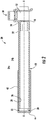
FIG. 2 is a cross-sectional view of the hot stick ofFIG. 1 in a retracted configuration according to an embodiment; -
FIG. 3 is a cross-sectional view of the hot stick ofFIG. 1 in an extended configuration according to an embodiment; -
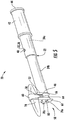
FIG. 4 is another perspective view of a hot stick according to an embodiment; -
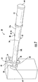
FIG. 5 is a perspective view of a hot stick having a probe mounted thereto according to an embodiment; -
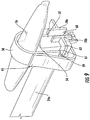
FIG. 6 is a perspective cross-sectional view of a hot stick according to an embodiment; -
FIG. 7 is a perspective view of a hot stick according to another embodiment; and -
FIG. 8 is a front view of a button having a channel feature according to an embodiment; and -
FIG. 9 is a perspective view of portion of a hot stick having a probe mounted thereto according to an embodiment; - The detailed description explains embodiments of the disclosure, together with advantages and features, by way of example with reference to the drawings.
- Referring now to the FIGS., an example of
tool 20 commonly referred to as a "hot stick" is illustrated. Thetool 20 is configured to allow a user to manipulate a piece of equipment from a selected distance away from a workpiece. For example, in an embodiment, thetool 20 may be suitable for electrical use up to 600 volts per ASTM and CSA standards. Alternatively, the tool may be suitable for electrical use up to 750 or 1000 volts. - As shown, the
tool 20 includes atelescoping arm 22 having a plurality of tubular sections 24 slidable along a longitudinal axis X of thetool 20 to vary the length thereof. In the illustrated, non-limiting embodiment, thearm 22 includes a firsttubular section 24a and a secondtubular section 24b movable between a retracted position (FIG. 2 ) and an extended position (FIG. 3 ). Although anarm 22 having only twotubular sections arm 22 having any number of sections 24 is within the scope of the disclosure. An outer diameter of the secondtubular section 24b is smaller than an inner diameter of the firsttubular section 24a such that all or a portion of the secondtubular section 24b is receivable within a hollow interior of the firsttubular section 24a. Accordingly, in the retracted position, all or a substantial portion of the firsttubular section 24a and the secondtubular section 24b are arranged in an overlapping configuration. - A
locking mechanism 26 is operable to lock thearm 22 in one or more of the extended and retracted positions. The firsttubular section 24a has afirst hole 28 formed adjacent afirst end 30 and asecond hole 32 formed adjacent the second,opposite end 34. Similarly, the secondtubular section 24b has ahole 36 formed adjacent afirst end 38 thereof. When thearm 22 is in the retracted position, thefirst holes tubular sections locking mechanism 26 engages thefirst holes tubular section 24b is restricted from moving relative to the firsttubular section 24a. In the extended position, thelocking mechanism 26 engages the alignedfirst hole 36 of the secondtubular section 24b and thesecond hole 32 of the firsttubular section 24a to restrict relative movement between the first and secondtubular sections arm 22 in combination with a user's arm is equal to or greater than a shock protection boundary set by industry electrical standards, such as NFPA 70E, for example. In an embodiment, thearm 22 has a length greater than or generally equal to about 21 inches in the extended position, and may be retracted to a length of between about 12 and 13 inches. - The
locking mechanism 26 is a resilient member, such as a clip mounted to the secondtubular section 24b for example, having at least one protrusion or detent 40 receivable within theholes locking mechanism 26 biases the detent 40 outwardly and into engagement with one ormore holes detent 40 is engaged with a pair of aligned holes, thelocking mechanism 26 may be able to withstand at least three pounds of shear force applied to thetubular sections arm 22. - To disengage the
locking mechanism 26 from ahole first arm section 24a, an inward force is applied thereto. When the detent 40 is disengaged from ahole tubular section 24a, thearm 22 is movable between the extended and retracted position. Although thearm 22 is described as telescoping, embodiments where thearm 22 is formed having a stationary length are also within the scope of the disclosure. Further, regardless of the configuration, thearm 22 is formed from a suitable non-conductive material, such as plastic for example. The arm may additionally include a coating to prevent great and dirt from accumulating thereon. - A
material 42 intended to provide a surface for easily gripping thearm 22 is wrapped about at least a portion of thearm 22. Although the grippingmaterial 42 is illustrated as being located at afirst end 44 of the arm, adjacent thefirst end 30 of the firsttubular section 24a, and has a length equal to about 6 inches, embodiments where the grippingmaterial 42 spans an entire length of the firsttubular section 24a or of theentire arm 22 are also within the scope of the disclosure. In an embodiment, thematerial 42 is a rubberized or foam material. However, any suitable non-conductive material is contemplated herein. - Located at the
distal end 46 of thearm 22, opposite the grippingmaterial 42, is aconnector 50. Theconnector 50 may be removably coupled to or fixedly attached to thearm 22. As shown, thebody 52 of theconnector 50 is generally rectangular in shape. However, any suitable shape is within the scope of the disclosure. Afirst surface 54 of theconnector 50 includes a generally non-planar surface. In an embodiment, the contour of thefirst surface 54 is generally complementary to a probe or other device 56 (seeFIG. 5 ) to be used with thetool 20. Examples of probes orother devices 56 suitable with thetool 20 include, but are not limited to, a proximity tester and a meter probe for example. - The
connector 50 additionally includes amechanism 58 configured to cooperate with thebody 52 to retain or hold the probe orother device 56. In the non-limiting embodiment ofFIGS. 1-7 , themechanism 58 includes anengagement portion 60 disposed adjacent thefirst surface 54. Theengagement portion 60 may also, but need not, have a contour generally complementary to a portion of the probe orother device 56. In an embodiment, one or both of thefirst surface 54 and theengagement portion 60 includes aninsert 62 having an enhanced gripping surface for preventing movement of a device in contact therewith. - The
mechanism 58 is movable to compress thedevice 56 between thefirst surface 54 and theengagement portion 60 thereof, best shown inFIG. 5 . Themechanism 58 in combination with theconnector 50 is suitable to retain a variety ofdevices 56 even when a force of up to three pounds is applied thereto in all directions. In the illustrated, non-limiting embodiment, themechanism 58 is movable about an axis Y oriented substantially perpendicular to the longitudinal axis X of thearm 22. However, embodiments where thearm 22 is movable about an axis parallel to the longitudinal axis X or is rotatable about an axis for example, are also within the scope of the disclosure. - In the illustrated, non-limiting embodiment, the
mechanism 58 is slidable within achannel 64 formed at a side of theconnector 50 to position theengagement portion 60 relative to thefirst surface 54. Themechanism 58 may function in a manner similar to a ratchet such that themechanism 58 is held or selectively retained at one of a plurality of positions relative to theconnector body 52. Themechanism 58 may include a tab orother feature 66 to allow a user to easily manipulate the position of themechanism 58 relative to theconnector body 54. - In another embodiment, best shown in
FIG. 9 , themovable mechanism 58 includes a strap coupled to thebody 52 of theconnector 50. For example, afirst end 59 of the strap may extend through aslot 61 formed in thebody 52, such as in aflange 63 extending from a side thereof. Thestrap 58 is configured to wrap around the probe orother device 56 to compress thedevice 56 between thefirst surface 54 and themechanism 58. The movable orfree end 65 of thestrap 58 may be configured to removably couple to a portion of theconnector 50, or alternatively, may couple to another portion of thestrap 58, as shown in the FIG. In an embodiment, thestrap 58 is formed from a Velcro material; however any suitable strap-like mechanism is contemplated herein. - The
tool 20 may additionally be adapted to manipulate one or more buttons. In such embodiments, anelongated member 68 may extend from a surface of theconnector body 52. Although the elongated memb er 68 is illustrated as being positioned at asurface 70 of theconnector body 52 opposite the portion of theconnector 50 mounted to thearm 22, theelongated member 68 may be disposed at any location about theconnector 50. As best shown inFIG. 6 , the thickness of theelongated member 68 is sized such that theelongated member 68 may be inserted between a mountingsurface 72 and abutton 74 movable axially towards and away from the plane of the mountingsurface 72. Accordingly, the elongated member 68b may be used to push or pull thebutton 74 in a desired direction. - In an embodiment, the
tool 20 is adapted for use in elevator applications. In such embodiments, theconnector 50 includes at least one feature 78 configured to engage and facilitate rotation of a corresponding button orknob 76, such as a button for controlling operation of the elevator car in an inspection mode for example. With reference toFIGS. 4 and7 , in the illustrated, non-limiting embodiment, theconnector body 52 includes afirst feature 78a and a substantially identicalsecond feature 78b. However, any number of features is contemplated herein. The features are rotated 180 degrees relative to one another such that the features are generally symmetrical about the correspondingsurface 70 of theconnector body 52. In embodiments where a shroud surrounds the button, as shown inFIG. 7 , the diameter defined by the plurality of features 78 is less than the diameter of the shroud for receipt therein. However, the features 78 may act to stabilize thetool 20 when being used in other applications. For example, the diameter defined by the features 78 may exceed a shroud associated with another button, such as a run button of an elevator control, thereby preventing accidental engagement with the button. - In the illustrated, non-limiting embodiment, the first and
second features clearance 80 there between. Thechannel 80 is complementary to achannel 82 formed in and protruding from the button 76 (seeFIG. 8 ). In use, a user can position thetool 20 such that thechannel 82 of thebutton 76 is received within thechannel 80 formed between thefeatures tool 20 in a desired direction to turn thebutton 76. It should be understood that the features 78 illustrated and described herein are specific to one type of button and that features having another configuration adapted for use with a different type of button are also within the scope of the disclosure. - While the disclosure has been described in detail in connection with only a limited number of embodiments, it should be readily understood that the disclosure is not limited to such disclosed embodiments. Rather, the disclosure can be modified to incorporate any number of variations, alterations, substitutions or equivalent arrangements not heretofore described, but which are commensurate with the spirit and scope of the disclosure. Additionally, while various embodiments of the disclosure have been described, it is to be understood that aspects of the disclosure may include only some of the described embodiments. Accordingly, the disclosure is not to be seen as limited by the foregoing description, but is only limited by the scope of the appended claims.
Claims (15)
- A hot stick for manipulating a probe from a position a selected distance away from a workpiece, the tool comprising:an arm;a connector coupled to the arm, the connector including a connector body having a contoured first surface; anda mechanism movable relative to the connector body and configured to cooperate with the first surface of the body to retain a probe.
- The hot stick of claim 1, wherein the hot stick is suitable for use in applications where the workpiece has 1000 volts or less; preferably 600 volts or less.
- The hot stick of claim 1 or 2, wherein the arm is a telescoping arm comprising a plurality of sections movable between a retracted position and an extended position.
- The hot stick of claim 3, wherein a resilient locking mechanism retains the arm in one of the extended position and the retracted position.
- The hot stick of any preceding claim, wherein a gripping material is positioned adjacent a first end of the arm.
- The hot stick of any preceding claim, wherein the arm, connector, and mechanism are formed from a non-conductive material.
- The hot stick of any preceding claim, wherein the mechanism is slidable within a channel formed in the connector body, the mechanism being selectively retained at a plurality of locations relative to the connector body.
- The hot stick of any preceding claim, wherein the mechanism includes an engagement portion located generally adjacent the first surface of the connector body, at least one of the engagement portion and the first surface having an insert for gripping the probe coupled thereto.
- The hot stick of any preceding claim, wherein the mechanism is a strap having at least one end removably coupled to the connector body; preferably wherein the strap is formed from a Velcro material.
- The hot stick of any preceding claim, wherein the connector body includes an elongated member operable to translate a button along an axis; and preferably wherein the button is an inspection button of an elevator.
- The hot stick of any preceding claim, wherein the connector body includes at least one feature operable to rotate a button about an axis.
- The hot stick of claim 11, wherein the at least one feature includes a substantially identical first feature and second feature, the first feature and the second feature being generally symmetrical about a corresponding surface of the connector body.
- The hot stick of claim 12, wherein the second feature is rotated 180 degrees relative to the first feature.
- The hot stick of claim 12 or 13, wherein a clearance is defined between the first feature and the second feature, the clearance being complementary to a channel of the button.
- The hot stick of any preceding claim, wherein the connector is fixedly attached to an end of the arm; or wherein the connector is integrally formed with an end of the arm.
Applications Claiming Priority (1)
| Application Number | Priority Date | Filing Date | Title |
|---|---|---|---|
| US201762575109P | 2017-10-20 | 2017-10-20 |
Publications (2)
| Publication Number | Publication Date |
|---|---|
| EP3476541A1 true EP3476541A1 (en) | 2019-05-01 |
| EP3476541B1 EP3476541B1 (en) | 2022-11-30 |
Family
ID=63914880
Family Applications (1)
| Application Number | Title | Priority Date | Filing Date |
|---|---|---|---|
| EP18201243.5A Active EP3476541B1 (en) | 2017-10-20 | 2018-10-18 | Reach tool for use in low voltage applications |
Country Status (3)
| Country | Link |
|---|---|
| US (1) | US10978262B2 (en) |
| EP (1) | EP3476541B1 (en) |
| CN (1) | CN109696567B (en) |
Families Citing this family (5)
| Publication number | Priority date | Publication date | Assignee | Title |
|---|---|---|---|---|
| US11904463B2 (en) | 2019-07-30 | 2024-02-20 | Abb Schweiz Ag | Plastic robot arm link, associated robot and manufacturing method |
| CN112466724B (en) * | 2019-09-06 | 2022-10-28 | 河南森源电气股份有限公司 | Energy storage handle and circuit breaker |
| US20210315769A1 (en) * | 2020-04-08 | 2021-10-14 | Bardia Shemiranipour | Universal Ischemic Compression Device |
| DE112022000660T5 (en) * | 2021-03-31 | 2023-11-02 | Fanuc Corporation | ARM-SHAPED STRUCTURE AND ROBOTS |
| US11961689B2 (en) * | 2021-07-07 | 2024-04-16 | Utility Solutions, Inc. | Load break tool having rotational flexibility |
Citations (5)
| Publication number | Priority date | Publication date | Assignee | Title |
|---|---|---|---|---|
| US2291593A (en) * | 1941-08-13 | 1942-07-28 | Chance Co Ab | Operating tool for high tension electric lines |
| DE20005517U1 (en) * | 2000-03-28 | 2001-02-22 | Franz, Edgar, 72537 Mehrstetten | Screwing, turning and holding tools based on spirally wound bands |
| US6283519B1 (en) * | 1998-07-17 | 2001-09-04 | Calvin E. Dutton | Lighting rod and method |
| US20050034884A1 (en) * | 2003-08-15 | 2005-02-17 | Lee Lon G. | Wildlife guard placement tool |
| GB2412346A (en) * | 2004-03-24 | 2005-09-28 | Ian Bannister | Apparatus for opening and closing a window |
Family Cites Families (73)
| Publication number | Priority date | Publication date | Assignee | Title |
|---|---|---|---|---|
| US854578A (en) * | 1906-08-23 | 1907-05-21 | Edward J Heath | Pick-up for non-insulated electric wires. |
| US942490A (en) | 1908-12-04 | 1909-12-07 | William John Dunn | Telescopic article. |
| US1741970A (en) | 1925-11-27 | 1929-12-31 | Tip S Tool Company Inc | Insulating safety tool for handling live wires, etc. |
| US1777395A (en) * | 1927-06-08 | 1930-10-07 | Chester C Coon | Wire clamp |
| US1744356A (en) | 1927-06-23 | 1930-01-21 | Tips Tool Company Inc | Operating device for hot-line clamps |
| US1724435A (en) | 1928-01-14 | 1929-08-13 | Earl W Studwell | Tool |
| US1920168A (en) | 1930-12-23 | 1933-08-01 | Henry W Bodendieck | Operating member or stick for hot line equipment |
| US2316204A (en) | 1941-01-27 | 1943-04-13 | Allison R Williams | Hot stick |
| US2538006A (en) | 1945-10-31 | 1951-01-16 | Arthur T Keppler | Wrench head having distal torque lever |
| US2868051A (en) | 1956-01-24 | 1959-01-13 | Burndy Corp | Hot stick tool with extension handles |
| US3182960A (en) | 1962-06-01 | 1965-05-11 | Alton A French | Electrician's wire fish pole |
| US3474833A (en) | 1966-08-26 | 1969-10-28 | Armed Forces Equipment Dev Cor | Telescoping tube assembly |
| US3473837A (en) | 1967-08-17 | 1969-10-21 | Daniel J Goodman | Hot stick |
| US3863145A (en) | 1973-08-29 | 1975-01-28 | Mc Graw Edison Co | Electrical fault detecting tool with fuse assembly and power line clamp device |
| US4047821A (en) | 1975-03-14 | 1977-09-13 | A. B. Chance Company | Break-resistant telescoping tool |
| US4004834A (en) | 1976-01-02 | 1977-01-25 | Alex Podpaly | Tappet follower retrieval tool |
| USD248209S (en) | 1976-08-16 | 1978-06-20 | Hydro Tube Corporation | Fireplace poker |
| US4079978A (en) | 1976-12-03 | 1978-03-21 | Hastings Fiber Glass Products, Inc. | Hot stick with air cushion |
| US4132441A (en) | 1977-10-17 | 1979-01-02 | Watkins Murrell W | Head for removing fuse holder |
| US4246436A (en) | 1978-09-20 | 1981-01-20 | Federal Cartridge Corporation | Junction enclosure assembly |
| US4470328A (en) | 1983-02-24 | 1984-09-11 | Kearney-National Inc. | Special tool |
| US4525006A (en) * | 1983-05-02 | 1985-06-25 | R.J. Levesque Manufacturing Co. | Electrical disconnect tool |
| US4582352A (en) * | 1984-11-29 | 1986-04-15 | Reinhard Filter | Live-line separable insulated connector tool |
| US4911039A (en) | 1988-10-20 | 1990-03-27 | Sol-Plex | Electric extension pole |
| US5171052A (en) | 1991-04-30 | 1992-12-15 | R&M Industries, Inc. | Manually operated load shifter |
| US5241870A (en) * | 1991-07-22 | 1993-09-07 | Intest Corporation | Test head manipulator |
| US5299464A (en) | 1991-11-22 | 1994-04-05 | Bennett James A | Hot stick transformer sampler |
| USD368748S (en) | 1994-07-25 | 1996-04-09 | Kellersohn Rudolph F | Golf tee placement setter |
| US5531494A (en) * | 1994-09-26 | 1996-07-02 | Singleton Technology, Inc. | Handle for control of mobile riding toys |
| US5593196A (en) | 1994-11-29 | 1997-01-14 | Hastings Fiber Glass Products, Inc. | Telescopic hot stick |
| US5730033A (en) | 1996-08-08 | 1998-03-24 | Mitrowski; Anthony D. | Florescent light bulb changing device |
| USD396392S (en) | 1997-09-12 | 1998-07-28 | Tda Buddy, Inc. | Manual manipulator |
| US6450557B1 (en) | 2001-03-16 | 2002-09-17 | Benjamin R. Martinez | Object retrieving device |
| US6473953B1 (en) | 2001-07-30 | 2002-11-05 | Raymond N. Portnoff | Wire gripper and method of installing decorative wire strings |
| US6474197B1 (en) * | 2001-08-31 | 2002-11-05 | Hastings Fiber Glass Products, Inc. | Cutout fuse tube installation tool |
| US6725745B1 (en) | 2002-05-28 | 2004-04-27 | Brian A Palmieri | Safety fuse tool |
| USD497086S1 (en) | 2004-01-12 | 2004-10-12 | Beulah Lopes | Accessory positioning device |
| USD505052S1 (en) | 2004-02-27 | 2005-05-17 | Thomas & Betts International, Inc. | Wire terminal installation tool |
| USD500433S1 (en) | 2004-03-08 | 2005-01-04 | Jeremiah Klaas | Wedge bolt removal tool |
| US7174260B2 (en) * | 2004-04-01 | 2007-02-06 | Blue Line Innovations Inc. | System and method for reading power meters |
| USD522326S1 (en) | 2005-03-25 | 2006-06-06 | Chance Donna R | Candle maintenance tool |
| USD605912S1 (en) | 2005-05-09 | 2009-12-15 | Teodoro Gonzalez | Fuse barrel removal tool |
| US7478851B2 (en) | 2006-07-05 | 2009-01-20 | Kenneth Geller | Vehicle hand tool |
| US20080265593A1 (en) | 2007-04-19 | 2008-10-30 | Gregory Woodworth | Hot stick devices, systems and method |
| US7721459B2 (en) | 2008-02-28 | 2010-05-25 | Cantega Technologies Inc. | Hot stick with measuring calipers |
| US7909376B1 (en) | 2008-09-23 | 2011-03-22 | Mckinley Larry W | Lineman's pole and hook assembly |
| US8056445B2 (en) | 2008-12-09 | 2011-11-15 | Jackson Iii Denton L | Multi-task-tool |
| US8459712B2 (en) | 2009-03-05 | 2013-06-11 | Home Depot Usa, Inc. | Apparatus for coupling and decoupling clips |
| US7984665B1 (en) | 2009-03-25 | 2011-07-26 | Robertson Kenny D | Hot stick switch head |
| US8061751B2 (en) | 2009-03-27 | 2011-11-22 | Ames True Temper, Inc. | Extendable reaching tool |
| US20110101716A1 (en) | 2009-10-30 | 2011-05-05 | Matthew Nolte | Utility pole with removable supporting push button |
| CN201678863U (en) | 2010-03-10 | 2010-12-22 | 王宏波 | Extensible clothes hanger |
| US9339917B2 (en) * | 2010-05-13 | 2016-05-17 | Kilvert, Llc | Meter puller with safety shield |
| USD656373S1 (en) | 2010-10-18 | 2012-03-27 | David Martin | Extendable pole |
| CN201876505U (en) | 2010-10-22 | 2011-06-22 | 山东省分析测试中心 | Remote ionizing radiation detecting device |
| CA2776761C (en) | 2011-05-12 | 2019-07-16 | Cantega Technologies Inc. | Tool and method for handling a part |
| US8752877B2 (en) | 2011-08-17 | 2014-06-17 | Daniel Spindler | Method and apparatus for installing decorative lights |
| USD711706S1 (en) | 2012-08-03 | 2014-08-26 | Earl Votolato | Telescoping reset/testing tool with interchangeable heads |
| EP2725363B9 (en) * | 2012-10-24 | 2015-03-25 | Multitest elektronische Systeme GmbH | Contact spring for a test socket for the high power testing of an electronic component |
| US9198500B2 (en) | 2012-12-21 | 2015-12-01 | Murray W. Davis | Portable self powered line mountable electric power line and environment parameter monitoring transmitting and receiving system |
| USD719423S1 (en) | 2013-02-26 | 2014-12-16 | Napier Limited | Hanging system |
| USD740722S1 (en) * | 2013-07-02 | 2015-10-13 | Helen Of Troy Limited | Stroller hook |
| US9656381B2 (en) | 2013-11-12 | 2017-05-23 | Cantega Technologies Inc. | Hot stick adapter, combination, and method |
| TWI678184B (en) * | 2014-04-25 | 2019-12-01 | 德派信迪思產品公司 | Aiming device system |
| US9853426B2 (en) * | 2014-09-11 | 2017-12-26 | Shining Sea Trading Company | Object manipulation device, system, and method |
| US9702503B2 (en) | 2015-04-22 | 2017-07-11 | Dyno Seasonal Solutions Llc | Multifunctional clip |
| USD772027S1 (en) | 2015-04-22 | 2016-11-22 | Dyno Seasonal Solutions Llc | Telescoping pole for hanging lights |
| CN204882795U (en) | 2015-06-10 | 2015-12-16 | 华电龙口发电股份有限公司 | Insulating measuring device of multi -functional integration |
| CN104989932B (en) | 2015-07-17 | 2017-03-08 | 苏州富士电梯有限公司 | The mounting tool of the Anti-reversal detection device on escalator or moving sidewalk |
| GB2544747A (en) * | 2015-11-24 | 2017-05-31 | Caterpillar Work Tools Bv | Apparatus and method for coupling work tool to a machine |
| CN106054033A (en) | 2016-05-19 | 2016-10-26 | 天津送变电工程公司 | Withstand voltage test wire telescopic insulating support and safe test method |
| CN106324295A (en) | 2016-08-10 | 2017-01-11 | 内蒙古电力(集团)有限责任公司内蒙古超高压供电局 | Device for fixing partial discharge live-line detector sensor |
| CN206038873U (en) | 2016-09-20 | 2017-03-22 | 广东电网有限责任公司惠州供电局 | Battery assistant measuring instrument |
-
2018
- 2018-10-15 US US16/160,681 patent/US10978262B2/en active Active
- 2018-10-18 EP EP18201243.5A patent/EP3476541B1/en active Active
- 2018-10-19 CN CN201811223799.5A patent/CN109696567B/en active Active
Patent Citations (5)
| Publication number | Priority date | Publication date | Assignee | Title |
|---|---|---|---|---|
| US2291593A (en) * | 1941-08-13 | 1942-07-28 | Chance Co Ab | Operating tool for high tension electric lines |
| US6283519B1 (en) * | 1998-07-17 | 2001-09-04 | Calvin E. Dutton | Lighting rod and method |
| DE20005517U1 (en) * | 2000-03-28 | 2001-02-22 | Franz, Edgar, 72537 Mehrstetten | Screwing, turning and holding tools based on spirally wound bands |
| US20050034884A1 (en) * | 2003-08-15 | 2005-02-17 | Lee Lon G. | Wildlife guard placement tool |
| GB2412346A (en) * | 2004-03-24 | 2005-09-28 | Ian Bannister | Apparatus for opening and closing a window |
Also Published As
| Publication number | Publication date |
|---|---|
| CN109696567B (en) | 2022-07-08 |
| US10978262B2 (en) | 2021-04-13 |
| US20190118393A1 (en) | 2019-04-25 |
| CN109696567A (en) | 2019-04-30 |
| EP3476541B1 (en) | 2022-11-30 |
Similar Documents
| Publication | Publication Date | Title |
|---|---|---|
| US10978262B2 (en) | Reach tool for use in low voltage applications | |
| US8922231B2 (en) | Method and apparatus for indexing an adjustable test probe tip | |
| JP3917332B2 (en) | Endoscope operation wire connecting part | |
| US10156591B2 (en) | Current meter | |
| JP6243407B2 (en) | Locking electrical connector | |
| JPWO2017195868A1 (en) | Gripping tool for indirect hot wire construction | |
| US5457392A (en) | Testing clip and circuit board contacting method | |
| KR102433911B1 (en) | Portable multi-tester probe | |
| US12338090B2 (en) | Support for adhesive tape | |
| US9006577B2 (en) | Apparatus for detachable attachment of an electrical conductor to a current transformer housing | |
| US5161301A (en) | Double-barrelled contact tool and method of using same | |
| EP2067650A1 (en) | Short circuit device | |
| US2857572A (en) | Electrical probe | |
| JP2015165739A (en) | Indirect live-line gripping tool | |
| JP5405645B1 (en) | Auxiliary grip and common operation bar with the same | |
| JP7228880B2 (en) | DC voltage detector | |
| US8591269B2 (en) | Shielding terminal clamp | |
| JP2016082810A (en) | Indirect hot-line tip tool, and indirect hot-line work instrument | |
| WO2020110158A1 (en) | Electric resistance welding apparatus | |
| KR20220106443A (en) | Probe device of instrument | |
| US6260455B1 (en) | Motor vehicle access device | |
| US12042923B2 (en) | Anti-pinch device for insulating implementations | |
| US20170225308A1 (en) | Clip installation tool | |
| JP5968937B2 (en) | Tip tool | |
| JP5944215B2 (en) | Flexible sensor |
Legal Events
| Date | Code | Title | Description |
|---|---|---|---|
| PUAI | Public reference made under article 153(3) epc to a published international application that has entered the european phase |
Free format text: ORIGINAL CODE: 0009012 |
|
| STAA | Information on the status of an ep patent application or granted ep patent |
Free format text: STATUS: THE APPLICATION HAS BEEN PUBLISHED |
|
| AK | Designated contracting states |
Kind code of ref document: A1 Designated state(s): AL AT BE BG CH CY CZ DE DK EE ES FI FR GB GR HR HU IE IS IT LI LT LU LV MC MK MT NL NO PL PT RO RS SE SI SK SM TR |
|
| AX | Request for extension of the european patent |
Extension state: BA ME |
|
| STAA | Information on the status of an ep patent application or granted ep patent |
Free format text: STATUS: REQUEST FOR EXAMINATION WAS MADE |
|
| 17P | Request for examination filed |
Effective date: 20191101 |
|
| RBV | Designated contracting states (corrected) |
Designated state(s): AL AT BE BG CH CY CZ DE DK EE ES FI FR GB GR HR HU IE IS IT LI LT LU LV MC MK MT NL NO PL PT RO RS SE SI SK SM TR |
|
| STAA | Information on the status of an ep patent application or granted ep patent |
Free format text: STATUS: EXAMINATION IS IN PROGRESS |
|
| 17Q | First examination report despatched |
Effective date: 20201106 |
|
| GRAP | Despatch of communication of intention to grant a patent |
Free format text: ORIGINAL CODE: EPIDOSNIGR1 |
|
| STAA | Information on the status of an ep patent application or granted ep patent |
Free format text: STATUS: GRANT OF PATENT IS INTENDED |
|
| RIC1 | Information provided on ipc code assigned before grant |
Ipc: B25G 3/20 20060101ALI20220517BHEP Ipc: H01R 11/14 20060101ALI20220517BHEP Ipc: H02G 1/02 20060101ALI20220517BHEP Ipc: B25G 1/12 20060101ALI20220517BHEP Ipc: B25G 1/04 20060101ALI20220517BHEP Ipc: B25B 9/00 20060101AFI20220517BHEP |
|
| RAP3 | Party data changed (applicant data changed or rights of an application transferred) |
Owner name: OTIS ELEVATOR COMPANY |
|
| INTG | Intention to grant announced |
Effective date: 20220607 |
|
| GRAS | Grant fee paid |
Free format text: ORIGINAL CODE: EPIDOSNIGR3 |
|
| GRAA | (expected) grant |
Free format text: ORIGINAL CODE: 0009210 |
|
| STAA | Information on the status of an ep patent application or granted ep patent |
Free format text: STATUS: THE PATENT HAS BEEN GRANTED |
|
| AK | Designated contracting states |
Kind code of ref document: B1 Designated state(s): AL AT BE BG CH CY CZ DE DK EE ES FI FR GB GR HR HU IE IS IT LI LT LU LV MC MK MT NL NO PL PT RO RS SE SI SK SM TR |
|
| REG | Reference to a national code |
Ref country code: CH Ref legal event code: EP Ref country code: GB Ref legal event code: FG4D |
|
| REG | Reference to a national code |
Ref country code: AT Ref legal event code: REF Ref document number: 1534323 Country of ref document: AT Kind code of ref document: T Effective date: 20221215 Ref country code: DE Ref legal event code: R096 Ref document number: 602018043582 Country of ref document: DE |
|
| REG | Reference to a national code |
Ref country code: IE Ref legal event code: FG4D |
|
| REG | Reference to a national code |
Ref country code: LT Ref legal event code: MG9D |
|
| REG | Reference to a national code |
Ref country code: NL Ref legal event code: MP Effective date: 20221130 |
|
| PG25 | Lapsed in a contracting state [announced via postgrant information from national office to epo] |
Ref country code: SE Free format text: LAPSE BECAUSE OF FAILURE TO SUBMIT A TRANSLATION OF THE DESCRIPTION OR TO PAY THE FEE WITHIN THE PRESCRIBED TIME-LIMIT Effective date: 20221130 Ref country code: PT Free format text: LAPSE BECAUSE OF FAILURE TO SUBMIT A TRANSLATION OF THE DESCRIPTION OR TO PAY THE FEE WITHIN THE PRESCRIBED TIME-LIMIT Effective date: 20230331 Ref country code: NO Free format text: LAPSE BECAUSE OF FAILURE TO SUBMIT A TRANSLATION OF THE DESCRIPTION OR TO PAY THE FEE WITHIN THE PRESCRIBED TIME-LIMIT Effective date: 20230228 Ref country code: LT Free format text: LAPSE BECAUSE OF FAILURE TO SUBMIT A TRANSLATION OF THE DESCRIPTION OR TO PAY THE FEE WITHIN THE PRESCRIBED TIME-LIMIT Effective date: 20221130 Ref country code: FI Free format text: LAPSE BECAUSE OF FAILURE TO SUBMIT A TRANSLATION OF THE DESCRIPTION OR TO PAY THE FEE WITHIN THE PRESCRIBED TIME-LIMIT Effective date: 20221130 Ref country code: ES Free format text: LAPSE BECAUSE OF FAILURE TO SUBMIT A TRANSLATION OF THE DESCRIPTION OR TO PAY THE FEE WITHIN THE PRESCRIBED TIME-LIMIT Effective date: 20221130 |
|
| REG | Reference to a national code |
Ref country code: AT Ref legal event code: MK05 Ref document number: 1534323 Country of ref document: AT Kind code of ref document: T Effective date: 20221130 |
|
| PG25 | Lapsed in a contracting state [announced via postgrant information from national office to epo] |
Ref country code: RS Free format text: LAPSE BECAUSE OF FAILURE TO SUBMIT A TRANSLATION OF THE DESCRIPTION OR TO PAY THE FEE WITHIN THE PRESCRIBED TIME-LIMIT Effective date: 20221130 Ref country code: PL Free format text: LAPSE BECAUSE OF FAILURE TO SUBMIT A TRANSLATION OF THE DESCRIPTION OR TO PAY THE FEE WITHIN THE PRESCRIBED TIME-LIMIT Effective date: 20221130 Ref country code: LV Free format text: LAPSE BECAUSE OF FAILURE TO SUBMIT A TRANSLATION OF THE DESCRIPTION OR TO PAY THE FEE WITHIN THE PRESCRIBED TIME-LIMIT Effective date: 20221130 Ref country code: IS Free format text: LAPSE BECAUSE OF FAILURE TO SUBMIT A TRANSLATION OF THE DESCRIPTION OR TO PAY THE FEE WITHIN THE PRESCRIBED TIME-LIMIT Effective date: 20230330 Ref country code: HR Free format text: LAPSE BECAUSE OF FAILURE TO SUBMIT A TRANSLATION OF THE DESCRIPTION OR TO PAY THE FEE WITHIN THE PRESCRIBED TIME-LIMIT Effective date: 20221130 Ref country code: GR Free format text: LAPSE BECAUSE OF FAILURE TO SUBMIT A TRANSLATION OF THE DESCRIPTION OR TO PAY THE FEE WITHIN THE PRESCRIBED TIME-LIMIT Effective date: 20230301 |
|
| PG25 | Lapsed in a contracting state [announced via postgrant information from national office to epo] |
Ref country code: NL Free format text: LAPSE BECAUSE OF FAILURE TO SUBMIT A TRANSLATION OF THE DESCRIPTION OR TO PAY THE FEE WITHIN THE PRESCRIBED TIME-LIMIT Effective date: 20221130 |
|
| PG25 | Lapsed in a contracting state [announced via postgrant information from national office to epo] |
Ref country code: SM Free format text: LAPSE BECAUSE OF FAILURE TO SUBMIT A TRANSLATION OF THE DESCRIPTION OR TO PAY THE FEE WITHIN THE PRESCRIBED TIME-LIMIT Effective date: 20221130 Ref country code: RO Free format text: LAPSE BECAUSE OF FAILURE TO SUBMIT A TRANSLATION OF THE DESCRIPTION OR TO PAY THE FEE WITHIN THE PRESCRIBED TIME-LIMIT Effective date: 20221130 Ref country code: EE Free format text: LAPSE BECAUSE OF FAILURE TO SUBMIT A TRANSLATION OF THE DESCRIPTION OR TO PAY THE FEE WITHIN THE PRESCRIBED TIME-LIMIT Effective date: 20221130 Ref country code: DK Free format text: LAPSE BECAUSE OF FAILURE TO SUBMIT A TRANSLATION OF THE DESCRIPTION OR TO PAY THE FEE WITHIN THE PRESCRIBED TIME-LIMIT Effective date: 20221130 Ref country code: CZ Free format text: LAPSE BECAUSE OF FAILURE TO SUBMIT A TRANSLATION OF THE DESCRIPTION OR TO PAY THE FEE WITHIN THE PRESCRIBED TIME-LIMIT Effective date: 20221130 Ref country code: AT Free format text: LAPSE BECAUSE OF FAILURE TO SUBMIT A TRANSLATION OF THE DESCRIPTION OR TO PAY THE FEE WITHIN THE PRESCRIBED TIME-LIMIT Effective date: 20221130 |
|
| PG25 | Lapsed in a contracting state [announced via postgrant information from national office to epo] |
Ref country code: SK Free format text: LAPSE BECAUSE OF FAILURE TO SUBMIT A TRANSLATION OF THE DESCRIPTION OR TO PAY THE FEE WITHIN THE PRESCRIBED TIME-LIMIT Effective date: 20221130 Ref country code: AL Free format text: LAPSE BECAUSE OF FAILURE TO SUBMIT A TRANSLATION OF THE DESCRIPTION OR TO PAY THE FEE WITHIN THE PRESCRIBED TIME-LIMIT Effective date: 20221130 |
|
| REG | Reference to a national code |
Ref country code: DE Ref legal event code: R097 Ref document number: 602018043582 Country of ref document: DE |
|
| PLBE | No opposition filed within time limit |
Free format text: ORIGINAL CODE: 0009261 |
|
| STAA | Information on the status of an ep patent application or granted ep patent |
Free format text: STATUS: NO OPPOSITION FILED WITHIN TIME LIMIT |
|
| 26N | No opposition filed |
Effective date: 20230831 |
|
| PG25 | Lapsed in a contracting state [announced via postgrant information from national office to epo] |
Ref country code: SI Free format text: LAPSE BECAUSE OF FAILURE TO SUBMIT A TRANSLATION OF THE DESCRIPTION OR TO PAY THE FEE WITHIN THE PRESCRIBED TIME-LIMIT Effective date: 20221130 |
|
| PG25 | Lapsed in a contracting state [announced via postgrant information from national office to epo] |
Ref country code: IT Free format text: LAPSE BECAUSE OF FAILURE TO SUBMIT A TRANSLATION OF THE DESCRIPTION OR TO PAY THE FEE WITHIN THE PRESCRIBED TIME-LIMIT Effective date: 20221130 Ref country code: MC Free format text: LAPSE BECAUSE OF FAILURE TO SUBMIT A TRANSLATION OF THE DESCRIPTION OR TO PAY THE FEE WITHIN THE PRESCRIBED TIME-LIMIT Effective date: 20221130 |
|
| REG | Reference to a national code |
Ref country code: CH Ref legal event code: PL |
|
| REG | Reference to a national code |
Ref country code: BE Ref legal event code: MM Effective date: 20231031 |
|
| PG25 | Lapsed in a contracting state [announced via postgrant information from national office to epo] |
Ref country code: LU Free format text: LAPSE BECAUSE OF NON-PAYMENT OF DUE FEES Effective date: 20231018 |
|
| GBPC | Gb: european patent ceased through non-payment of renewal fee |
Effective date: 20231018 |
|
| PG25 | Lapsed in a contracting state [announced via postgrant information from national office to epo] |
Ref country code: LU Free format text: LAPSE BECAUSE OF NON-PAYMENT OF DUE FEES Effective date: 20231018 |
|
| PG25 | Lapsed in a contracting state [announced via postgrant information from national office to epo] |
Ref country code: GB Free format text: LAPSE BECAUSE OF NON-PAYMENT OF DUE FEES Effective date: 20231018 |
|
| PG25 | Lapsed in a contracting state [announced via postgrant information from national office to epo] |
Ref country code: CH Free format text: LAPSE BECAUSE OF NON-PAYMENT OF DUE FEES Effective date: 20231031 |
|
| PG25 | Lapsed in a contracting state [announced via postgrant information from national office to epo] |
Ref country code: GB Free format text: LAPSE BECAUSE OF NON-PAYMENT OF DUE FEES Effective date: 20231018 Ref country code: CH Free format text: LAPSE BECAUSE OF NON-PAYMENT OF DUE FEES Effective date: 20231031 |
|
| PG25 | Lapsed in a contracting state [announced via postgrant information from national office to epo] |
Ref country code: BE Free format text: LAPSE BECAUSE OF NON-PAYMENT OF DUE FEES Effective date: 20231031 |
|
| PG25 | Lapsed in a contracting state [announced via postgrant information from national office to epo] |
Ref country code: IE Free format text: LAPSE BECAUSE OF NON-PAYMENT OF DUE FEES Effective date: 20231018 |
|
| PG25 | Lapsed in a contracting state [announced via postgrant information from national office to epo] |
Ref country code: IE Free format text: LAPSE BECAUSE OF NON-PAYMENT OF DUE FEES Effective date: 20231018 |
|
| PG25 | Lapsed in a contracting state [announced via postgrant information from national office to epo] |
Ref country code: BG Free format text: LAPSE BECAUSE OF FAILURE TO SUBMIT A TRANSLATION OF THE DESCRIPTION OR TO PAY THE FEE WITHIN THE PRESCRIBED TIME-LIMIT Effective date: 20221130 |
|
| PG25 | Lapsed in a contracting state [announced via postgrant information from national office to epo] |
Ref country code: BG Free format text: LAPSE BECAUSE OF FAILURE TO SUBMIT A TRANSLATION OF THE DESCRIPTION OR TO PAY THE FEE WITHIN THE PRESCRIBED TIME-LIMIT Effective date: 20221130 |
|
| PG25 | Lapsed in a contracting state [announced via postgrant information from national office to epo] |
Ref country code: CY Free format text: LAPSE BECAUSE OF FAILURE TO SUBMIT A TRANSLATION OF THE DESCRIPTION OR TO PAY THE FEE WITHIN THE PRESCRIBED TIME-LIMIT; INVALID AB INITIO Effective date: 20181018 |
|
| PG25 | Lapsed in a contracting state [announced via postgrant information from national office to epo] |
Ref country code: HU Free format text: LAPSE BECAUSE OF FAILURE TO SUBMIT A TRANSLATION OF THE DESCRIPTION OR TO PAY THE FEE WITHIN THE PRESCRIBED TIME-LIMIT; INVALID AB INITIO Effective date: 20181018 |
|
| PGFP | Annual fee paid to national office [announced via postgrant information from national office to epo] |
Ref country code: FR Payment date: 20250924 Year of fee payment: 8 |
|
| PG25 | Lapsed in a contracting state [announced via postgrant information from national office to epo] |
Ref country code: TR Free format text: LAPSE BECAUSE OF FAILURE TO SUBMIT A TRANSLATION OF THE DESCRIPTION OR TO PAY THE FEE WITHIN THE PRESCRIBED TIME-LIMIT Effective date: 20221130 |
|
| PGFP | Annual fee paid to national office [announced via postgrant information from national office to epo] |
Ref country code: DE Payment date: 20250923 Year of fee payment: 8 |