EP3476002B1 - Wässrige tintenzusammensetzungen - Google Patents
Wässrige tintenzusammensetzungen Download PDFInfo
- Publication number
- EP3476002B1 EP3476002B1 EP17734419.9A EP17734419A EP3476002B1 EP 3476002 B1 EP3476002 B1 EP 3476002B1 EP 17734419 A EP17734419 A EP 17734419A EP 3476002 B1 EP3476002 B1 EP 3476002B1
- Authority
- EP
- European Patent Office
- Prior art keywords
- ink composition
- optionally
- aqueous ink
- particles
- aqueous
- Prior art date
- Legal status (The legal status is an assumption and is not a legal conclusion. Google has not performed a legal analysis and makes no representation as to the accuracy of the status listed.)
- Active
Links
Images



Classifications
-
- H—ELECTRICITY
- H01—ELECTRIC ELEMENTS
- H01M—PROCESSES OR MEANS, e.g. BATTERIES, FOR THE DIRECT CONVERSION OF CHEMICAL ENERGY INTO ELECTRICAL ENERGY
- H01M4/00—Electrodes
- H01M4/86—Inert electrodes with catalytic activity, e.g. for fuel cells
- H01M4/88—Processes of manufacture
- H01M4/8825—Methods for deposition of the catalytic active composition
- H01M4/8828—Coating with slurry or ink
- H01M4/8832—Ink jet printing
-
- C—CHEMISTRY; METALLURGY
- C09—DYES; PAINTS; POLISHES; NATURAL RESINS; ADHESIVES; COMPOSITIONS NOT OTHERWISE PROVIDED FOR; APPLICATIONS OF MATERIALS NOT OTHERWISE PROVIDED FOR
- C09D—COATING COMPOSITIONS, e.g. PAINTS, VARNISHES OR LACQUERS; FILLING PASTES; CHEMICAL PAINT OR INK REMOVERS; INKS; CORRECTING FLUIDS; WOODSTAINS; PASTES OR SOLIDS FOR COLOURING OR PRINTING; USE OF MATERIALS THEREFOR
- C09D11/00—Inks
- C09D11/30—Inkjet printing inks
- C09D11/32—Inkjet printing inks characterised by colouring agents
- C09D11/322—Pigment inks
-
- H—ELECTRICITY
- H01—ELECTRIC ELEMENTS
- H01M—PROCESSES OR MEANS, e.g. BATTERIES, FOR THE DIRECT CONVERSION OF CHEMICAL ENERGY INTO ELECTRICAL ENERGY
- H01M4/00—Electrodes
- H01M4/86—Inert electrodes with catalytic activity, e.g. for fuel cells
- H01M4/88—Processes of manufacture
- H01M4/8878—Treatment steps after deposition of the catalytic active composition or after shaping of the electrode being free-standing body
- H01M4/8882—Heat treatment, e.g. drying, baking
-
- H—ELECTRICITY
- H01—ELECTRIC ELEMENTS
- H01M—PROCESSES OR MEANS, e.g. BATTERIES, FOR THE DIRECT CONVERSION OF CHEMICAL ENERGY INTO ELECTRICAL ENERGY
- H01M4/00—Electrodes
- H01M4/86—Inert electrodes with catalytic activity, e.g. for fuel cells
- H01M4/90—Selection of catalytic material
- H01M4/9016—Oxides, hydroxides or oxygenated metallic salts
- H01M4/9025—Oxides specially used in fuel cell operating at high temperature, e.g. SOFC
-
- H—ELECTRICITY
- H01—ELECTRIC ELEMENTS
- H01M—PROCESSES OR MEANS, e.g. BATTERIES, FOR THE DIRECT CONVERSION OF CHEMICAL ENERGY INTO ELECTRICAL ENERGY
- H01M4/00—Electrodes
- H01M4/86—Inert electrodes with catalytic activity, e.g. for fuel cells
- H01M4/90—Selection of catalytic material
- H01M4/9016—Oxides, hydroxides or oxygenated metallic salts
- H01M4/9025—Oxides specially used in fuel cell operating at high temperature, e.g. SOFC
- H01M4/9033—Complex oxides, optionally doped, of the type M1MeO3, M1 being an alkaline earth metal or a rare earth, Me being a metal, e.g. perovskites
-
- H—ELECTRICITY
- H01—ELECTRIC ELEMENTS
- H01M—PROCESSES OR MEANS, e.g. BATTERIES, FOR THE DIRECT CONVERSION OF CHEMICAL ENERGY INTO ELECTRICAL ENERGY
- H01M8/00—Fuel cells; Manufacture thereof
- H01M8/10—Fuel cells with solid electrolytes
- H01M8/12—Fuel cells with solid electrolytes operating at high temperature, e.g. with stabilised ZrO2 electrolyte
- H01M8/124—Fuel cells with solid electrolytes operating at high temperature, e.g. with stabilised ZrO2 electrolyte characterised by the process of manufacturing or by the material of the electrolyte
- H01M8/1246—Fuel cells with solid electrolytes operating at high temperature, e.g. with stabilised ZrO2 electrolyte characterised by the process of manufacturing or by the material of the electrolyte the electrolyte consisting of oxides
- H01M8/1253—Fuel cells with solid electrolytes operating at high temperature, e.g. with stabilised ZrO2 electrolyte characterised by the process of manufacturing or by the material of the electrolyte the electrolyte consisting of oxides the electrolyte containing zirconium oxide
-
- H—ELECTRICITY
- H01—ELECTRIC ELEMENTS
- H01M—PROCESSES OR MEANS, e.g. BATTERIES, FOR THE DIRECT CONVERSION OF CHEMICAL ENERGY INTO ELECTRICAL ENERGY
- H01M8/00—Fuel cells; Manufacture thereof
- H01M8/10—Fuel cells with solid electrolytes
- H01M8/12—Fuel cells with solid electrolytes operating at high temperature, e.g. with stabilised ZrO2 electrolyte
- H01M8/124—Fuel cells with solid electrolytes operating at high temperature, e.g. with stabilised ZrO2 electrolyte characterised by the process of manufacturing or by the material of the electrolyte
- H01M8/1246—Fuel cells with solid electrolytes operating at high temperature, e.g. with stabilised ZrO2 electrolyte characterised by the process of manufacturing or by the material of the electrolyte the electrolyte consisting of oxides
- H01M8/126—Fuel cells with solid electrolytes operating at high temperature, e.g. with stabilised ZrO2 electrolyte characterised by the process of manufacturing or by the material of the electrolyte the electrolyte consisting of oxides the electrolyte containing cerium oxide
-
- H—ELECTRICITY
- H01—ELECTRIC ELEMENTS
- H01M—PROCESSES OR MEANS, e.g. BATTERIES, FOR THE DIRECT CONVERSION OF CHEMICAL ENERGY INTO ELECTRICAL ENERGY
- H01M8/00—Fuel cells; Manufacture thereof
- H01M8/10—Fuel cells with solid electrolytes
- H01M8/12—Fuel cells with solid electrolytes operating at high temperature, e.g. with stabilised ZrO2 electrolyte
- H01M2008/1293—Fuel cells with solid oxide electrolytes
-
- Y—GENERAL TAGGING OF NEW TECHNOLOGICAL DEVELOPMENTS; GENERAL TAGGING OF CROSS-SECTIONAL TECHNOLOGIES SPANNING OVER SEVERAL SECTIONS OF THE IPC; TECHNICAL SUBJECTS COVERED BY FORMER USPC CROSS-REFERENCE ART COLLECTIONS [XRACs] AND DIGESTS
- Y02—TECHNOLOGIES OR APPLICATIONS FOR MITIGATION OR ADAPTATION AGAINST CLIMATE CHANGE
- Y02E—REDUCTION OF GREENHOUSE GAS [GHG] EMISSIONS, RELATED TO ENERGY GENERATION, TRANSMISSION OR DISTRIBUTION
- Y02E60/00—Enabling technologies; Technologies with a potential or indirect contribution to GHG emissions mitigation
- Y02E60/30—Hydrogen technology
- Y02E60/50—Fuel cells
-
- Y—GENERAL TAGGING OF NEW TECHNOLOGICAL DEVELOPMENTS; GENERAL TAGGING OF CROSS-SECTIONAL TECHNOLOGIES SPANNING OVER SEVERAL SECTIONS OF THE IPC; TECHNICAL SUBJECTS COVERED BY FORMER USPC CROSS-REFERENCE ART COLLECTIONS [XRACs] AND DIGESTS
- Y02—TECHNOLOGIES OR APPLICATIONS FOR MITIGATION OR ADAPTATION AGAINST CLIMATE CHANGE
- Y02P—CLIMATE CHANGE MITIGATION TECHNOLOGIES IN THE PRODUCTION OR PROCESSING OF GOODS
- Y02P70/00—Climate change mitigation technologies in the production process for final industrial or consumer products
- Y02P70/50—Manufacturing or production processes characterised by the final manufactured product
Definitions
- This invention relates to metal-oxide based aqueous ink compositions for 3D inkjet printing components, primarily for high-temperature electrochemical devices.
- YSZ yttria-stabilized zirconia
- SOFCs solid oxide fuel cells
- SOEs electrolysers
- the gas-tight electrolyte is an oxide ion conductor, e.g. YSZ, that is mixed with an electronic conducting phase in both the positive and negative electrodes, e.g. respectively, nickel and lanthanum strontium manganite (LSM) for an SOFC.
- the electronic connections are usually made with silver or platinum wires, fixed to the electrodes by a conductive paste.
- Additive manufacturing techniques offer the potential to fabricate the functional layers of SOFCs with high reproducibility and level of customization.
- Inkjet printing is particularly suited to fabrication of thin films from precursor colloidal particle dispersions ('inks') ( C. Li et al., J. Power Sources 2015, 273, 465 ), and has been deployed to produce layers of YSZ ( V. Esposito et al., J. Power Sources 2015, 273, 89 ), YSZ pillars and cavities, using an entirely organic-based ink ( M.
- Inks typically employ an organic solvent in which to disperse particles due to their relatively high viscosity and low surface tension, compared to water, ensuring printability, defined as the reproducible ejection of droplets with consistent geometry.
- organic solvents have detrimental environmental and industrial impacts.
- Aqueous solvents are preferable commercially and environmentally, but have been avoided largely due to difficulty in formulating stable (to aggregation) dispersions and resultant cracking in printed structures during drying, due to capillary effects arising from the comparatively high surface tension of water.
- KR 2013 0047175 describes a preparation method of solid oxide fuel cell having ceramic granule, and a fabrication thereof.
- US 2014/352573 describes an inkjet ink including a pigment incorporated in an aqueous ink vehicle.
- US 2013/059223 describes a process for producing tubular ceramic structures of non-circular cross section.
- US 2010/242789 describes a method for producing water-repellent treated aluminum pigment dispersion, water-repellent treated aluminum pigment and aqueous ink composition containing the same.
- US 2009/181309 describes an electrode, lithium battery, method of manufacturing electrode and a composition for coating the electrode.
- the invention provides an aqueous ink composition comprising:
- the metal compound may be a metal oxide.
- the particles may comprise a metal or a metal oxide or a mixture thereof, preferably a metal oxide.
- the particles may comprise zirconium, yttrium, lanthanum, strontium, manganese, nickel, cobalt, cerium, gallium, silver or gadolinium or mixtures thereof, preferably an oxide of zirconium, yttrium, lanthanum, strontium, manganese, nickel, cobalt, cerium, silver or gadolinium or mixtures thereof.
- the particles may comprise yttria-stabilised zirconia (YSZ), lanthanum nickelates, lanthanum strontium manganite (LSM), lanthanum cobaltites (e.g.
- the particles comprise yttria-stabilised zirconia (YSZ), preferably wherein the particles consist essentially of YSZ. More preferably the particles comprise (preferably consist essentially of) 8 mol% yttria-stabilised zirconia.
- the particles may consist essentially of the metals, metal compounds or a mixture thereof, as described above.
- the particles comprising a metal or a metal compound or a mixture thereof may have an average particle diameter about 1000 nm or less, about 100 to about 800 nm, preferably about 100 to about 750 nm, preferably about 100 to about 700 nm.
- the particles comprising a metal or a metal compound or a mixture thereof may have an average particle diameter about 300 to about 800 nm or about 400 to about 800 nm.
- the dispersant may be an electrostatic dispersant, preferably wherein the electrostatic dispersant is a salt of a carboxylic acid, preferably an acrylic polymer (for example a sodium salt or an ammonium salt, preferably an ammonium salt), or a steric dispersant, preferably wherein the steric dispersant is polyvinylpyrrolidone.
- the dispersant may be an ionic dispersant, or a non-ionic dispersant or a combination of any of the above dispersants.
- the dispersant is an electrostatic dispersant, preferably wherein the electrostatic dispersant is an ammonium salt of a carboxylic acid, preferably an ammonium salt of an acrylic polymer.
- the polymeric binder may be a polyether.
- the polymeric binder may have a number average molecular weight of about 20000 to about 60000 Da.
- Preferably the polymeric binder is polyethylene glycol, preferably polyethylene glycol having a number average molecular weight of about 25000 to about 50000 Da.
- the non-ionic surfactant may be an alcohol alkoxylate surfactant, preferably an alcohol ethoxylate surfactant.
- the aqueous solvent may comprise at least 95% water (w/w).
- the aqueous solvent is preferably deionised water.
- the aqueous ink composition may have a solids loading from about 1 to about 50 wt%, preferably from about 3 to about 30 wt%, calculated as wt% of the total aqueous ink composition (w/w). Therefore, the aqueous ink composition may comprise from about 1 to about 50 wt%, preferably from about 3 to about 30 wt%, of the metal or a metal compound.
- the dispersant may be present in the aqueous ink composition at an amount of about 0.1 to about 1 mg m -2 of the surface area of the particles comprising a metal or a metal compound or a mixture thereof, preferably about 0.2 to about 0.8 mg m -2 .
- the polymeric binder may be present in the aqueous ink composition at a concentration of about 10 to about 50 mg cm -3 , preferably about 20 to about 40 mg cm -3 .
- the non-ionic surfactant may be present in the aqueous ink composition at a concentration of about 0.1 to about 0.5 mg cm -3 , preferably about 0.2 mg cm -3 .
- the aqueous ink composition may have a dynamic viscosity of about 2 to about 20 mPa s, preferably about 4 to about 15 mPa s, calculated at 20 °C using a viscometer, for example a DV-E viscometer (Brookfield, UK).
- the aqueous ink composition may have a printability (Oh -1 ) of about 1 to about 14, preferably about 4.5 to about 10.
- the aqueous ink composition may have a critical cracking thickness of at least 10 ⁇ m, preferably at least 15 ⁇ m.
- the invention provides a method of preparing an aqueous ink composition as described herein comprising the steps of:
- the dispersant is preferably selected from an electrostatic dispersant, a steric dispersant, an ionic dispersant, a non-ionic dispersant or a combination thereof.
- step (b) is carried out after step (a).
- the method preferably further comprising the step of concentrating the aqueous dispersion by removal of the aqueous solvent before adding the polymeric binder and the non-ionic surfactant.
- the method may also comprise the step of centrifugation and/or filtration of the aqueous dispersion of step (b) to remove larger particles comprising a metal or a metal compound or a mixture thereof before adding the polymeric binder and the non-ionic surfactant.
- the particles comprising a metal or a metal compound or a mixture thereof may be dispersed in the aqueous solvent by sonication.
- the invention provides the use of the aqueous ink composition described herein as an ink for 3D printing, preferably 3D inkjet printing.
- the invention provides the use of the aqueous ink composition described herein as an ink for printing a component of an electrical device, preferably the electrolyte phase or an electrode of a solid oxide electrochemical device, preferably an electrochemical reactor, preferably a solid oxide fuel cell or a solid oxide electrolyser or a membrane.
- the aqueous ink composition described herein may be used to print an individual component of an electrical device (for example an electrolyte phase or an electrode) which may then be used to form the electrochemical device or aqueous ink composition described herein may be used to print a component of an electrical device by printing the component in situ (for example, by printing an electrolyte phase directly onto an electrode).
- the invention provides a method of producing a printed article comprising the steps of:
- the method may further comprise the step of preparing an aqueous ink composition according to the second aspect of the invention, prior to step (b).
- the step of printing the aqueous ink composition may comprise printing one or more layers of the aqueous ink composition on the substrate to a thickness of about 1 to about 500 ⁇ m.
- the step of printing the aqueous ink composition may comprise printing a 3D microstructure (for example, a micropillar) of the aqueous ink composition.
- the critical cracking thickness of the printed aqueous ink composition may be at least 10 ⁇ m, preferably at least 15 ⁇ m.
- the structures may be dried and then optionally heat treated.
- the drying may be according to methods known in the art. Drying may be in air or in a convective oven with or without humidity control.
- the step of heat treating the printed article may comprise heating the ink to at least about 400 °C, to remove the organic phase, preferably between about 400 and about 700 °C.
- the heat treatment comprises heating the ink at about 600 °C; the actual temperature and rate of heating can be determined by thermo-gravimetric analysis.
- the heat treatment may further comprise a sintering step.
- the sintering step may comprise heating the ink to about 1000 to about 1800 °C, preferably about 1000 to about 1500 °C.
- the sintering step may be carried out sequentially or separately to the initial heat treatment step. For example, two or more layers of an aqueous ink composition are printed, wherein each layer may be heat treated and then the printed layers may be co-sintered.
- the substrate may be an electrode in a solid oxide fuel cell or a solid oxide electrolyser, and the aqueous ink composition may be used to print the electrolyte phase of the solid oxide fuel cell or solid oxide electrolyser.
- the aqueous ink composition may also be used to print the electrode, which may then be used as a substrate to print the electrolyte phase or the aqueous ink composition may be used to print the electrode on the electrolyte phase.
- the invention provides an article obtainable by printing an aqueous ink composition as described herein or as produced by a method according to the fifth aspect of the invention.
- the article may be a component in a solid oxide electrochemical device, preferably a reactor, preferably a solid oxide fuel cell, a solid oxide electrolyser or a membrane.
- the invention provides a solid oxide electrochemical device comprising an article obtainable by printing an aqueous ink composition as described herein or as produced by a method according to the fifth aspect of the invention, preferably wherein the solid oxide electrochemical device is a solid oxide fuel cell or a solid oxide electrolyser.
- the invention provides a method of producing a solid oxide electrochemical device comprising the step of printing an aqueous ink composition as described herein or as produced by a method described herein, preferably wherein the solid oxide electrochemical device is a solid oxide fuel cell or a solid oxide electrolyser.
- Embodiments described herein in relation to the first aspect of the invention apply mutatis mutandis to the second to eighth aspects of the invention.
- the invention provides an aqueous ink composition comprising:
- the aqueous ink composition of the invention comprises a colloidal dispersion of particles comprising a metal or a metal compound or a mixture thereof in an aqueous solvent.
- This aqueous ink composition may be essentially colloidally stable to aggregation. Any aggregates that may form may be dispersed by ultrasonication.
- the stability of aqueous ink composition of the invention may be quantified by measuring the zeta potential, the surface charge, or the particle size distribution over time of the ink composition, in accordance with standard protocols in the art.
- an aqueous solvent is a solvent that comprises at least 95% water (w/w).
- the aqueous solvent is deionised water.
- the pH of the aqueous solvent is in the region of thermodynamic stability of the dispersed particles comprising a metal or a metal compound or a mixture thereof.
- an aqueous solvent at about pH 9-10, or higher would be preferable, subject to the pH constraint imposed by the printhead material, and for an ink comprising particles comprising yttria-stabilised zirconia, an aqueous solvent at about pH 7 would be preferable.
- the particles comprising a metal or a metal compound or a mixture thereof preferably comprise zirconium, yttrium, lanthanum, strontium, manganese, nickel, cobalt, cerium, silver or gadolinium or mixtures thereof.
- These particles may be particles of a ceramic material, for example a metal oxide.
- the particles comprise oxides of zirconium, yttrium, lanthanum, strontium, manganese, nickel, cobalt, cerium, silver or gadolinium or mixtures thereof.
- Exemplary materials for the particles include yttria-stabilised zirconia (YSZ), lanthanum nickelates, lanthanum strontium manganite (LSM), lanthanum cobaltites (e.g.
- the particles are particles of yttria-stabilised zirconia, preferably 8 mol% yttria-stabilised zirconia (a material comprising a compound of formula (Y 2 O 3 ) 0.08 (ZrO 2 ) 0.92 ).
- the particles may have an average particle diameter of about 1000 nm or less, preferably about 100 to about 800 nm.
- the particles comprising a metal or a metal compound or a mixture thereof may, preferably, have an upper particle size limit of about 2 % of the diameter of the printhead nozzles used to print the aqueous ink composition, for example if the nozzle is 50 micrometres in diameter, the maximum particle size that may be ejected is about 1 ⁇ m.
- average particle size refers to the modal value of a particle size distribution, for example the modal intensity count value of a distribution of particle sizes measured by dynamic light scattering (DLS) using a light scattering detector, for example that of a Zetasizer ⁇ V instrument (Malvern, UK). Intensity counts are the first order output for samples measured by dynamic light scattering (DLS) using a light scattering detector. For example, in Figure 1 , the distribution of particle sizes in inks 1 to 5 is shown, where the average particles size for the particles in each ink is the modal intensity count value of the distribution.
- DLS dynamic light scattering
- particle sizes may be determined by diluting a dispersed particle sample in an aqueous solvent sufficiently to allow DLS to be applied, using a Zetasizer ⁇ V instrument (Malvern, UK).
- Ultrasonication may be carried out on the particles comprising a metal or a metal compound to break up aggregates and narrow the particle size distribution, improving the dispersion properties.
- the aqueous ink composition of the invention may have a solids loading from about 1 to about 50 wt%, preferably from about 3 to about 30 wt%.
- the solids loading is calculated as a weight % of the particles comprising a metal or a metal compound or a mixture thereof of the total weight of the ink composition (including the solvent), so represents the proportion of the ink composition made up of the metal or a metal compound.
- a dispersant is included in the aqueous ink composition to electrostatically and/or sterically stabilise the dispersion of the particles comprising a metal or a metal compound or a mixture thereof, for example by inducing a surface charge on the particles.
- This dispersant may form a functional layer on the surface of the particles comprising a metal or a metal compound or a mixture thereof.
- the dispersant may be an electrostatic dispersant, preferably wherein the electrostatic dispersant is a salt of a carboxylic acid (e.g. an acrylic polymer), or a steric dispersant, preferably wherein the steric dispersant is polyvinylpyrrolidone. Moreover, the dispersant may be an ionic dispersant or a non-ionic dispersant. The dispersant may be a combination of any of the above dispersants. Preferably the dispersant is an electrostatic dispersant or a steric dispersant or a combination thereof. Preferably an electrostatic dispersant, wherein the electrostatic dispersant is an ammonium salt of a carboxylic acid (for example, an acrylic polymer).
- the electrostatic dispersant is an ammonium salt of a carboxylic acid (for example, an acrylic polymer).
- An electrostatic dispersant is a compound that may adsorb to the surface of a substrate and induce an electrical charge of the surface of the substrate.
- an electrostatic dispersant itself has an electrical charge (i.e. is an ionic dispersant) and may transfer the charge to the substrate.
- An exemplary charged group that may be present in an electrostatic dispersant to give the dispersant an electrical charge is a carboxylate group (i.e., a -COO - group). It will be appreciated that a compound comprising a carboxylate group may be provided as a salt (preferably an ammonium salt).
- An electrostatic dispersant is preferably a compound having a number average molecular weight of less than about 10000 Daltons (Da), preferably less than about 8000 Da, preferably less than about 6000 Da. Accordingly, an electrostatic dispersant is preferably a compound having a number average molecular weight of less than about 8000 Da (preferably less than about 6000 Da or less than about 4000 Da) and comprising one or more carboxylate groups, preferably two or more carboxylate groups, preferably three or more carboxylate groups.
- an electrostatic dispersant is a polymer having charged groups in side chains (a polyelectrolyte), for example a poly carboxylic acid.
- An electrostatic dispersant having at least one carboxylic acid functionality may be used in the ink composition.
- the electrostatic dispersant is the salt of the corresponding carboxylic acid.
- the nature of the counter ion of the carboxylic acid salt electrostatic dispersant should be removed during heat treatment.
- the electrostatic dispersant is preferably an ammonium salt of an acrylic polymer, so the counter ion is ammonium.
- an acrylic polymer (used interchangeably herein with polyacrylic acid) refers to a polymer comprising a plurality of repeat units: or a salt thereof, wherein each of R' and R" is independently H or C 1-6 alkyl.
- each R' is H and each R" is H or C 1-6 alkyl (preferably methyl), preferably H.
- the polymer preferably comprises at least 10, at least 20, at least 50, at least 100 repeat units or at least 200 repeat units.
- a polymer may be terminated by any group, for example hydrogen.
- the polymer may be a homopolymer or a copolymer comprising two or more different repeat unit structures.
- the polymer may have a number average molecular weight of about 1000 to about 10000 Daltons (Da), preferably about 1000 to about 4000 Da, preferably about 2000 to about 6000 Da, preferably about 2000 to about 4000 Da, preferably about 4000 Da.
- the dispersant is Dispex ® A40 (Ciba-BASF), an ammonium salt of a polyacrylic acid.
- a polyacrylic acid, or a salt thereof may be a polymer formed from monomers of structure or a salt thereof (for example, an ammonium salt), wherein R' and R" are as described above.
- An electrostatic dispersant may be a salt (for example, an ammonium salt) of a compound comprising one or more optionally substituted benzoic acid moieties, preferably two or more, preferably wherein the one or more or two or more optionally substituted benzoic acid moieties are linked by conjugation.
- an electrostatic dispersant may be an ammonium salt of aurintricarboxylic acid (aluminon).
- Aluminon has the structure:
- Electrostatic dispersants as described herein are particularly advantageous in the ink composition of the invention as they are easily removed from the printed ink composition during the heat treatment step.
- a steric dispersant may be used in the ink composition.
- the steric dispersant may be polyvinyl pyrrolidone (PVP), preferably having a number average molecular weight of about 8000 to about 50000 Daltons (Da), preferably about 40000 Da.
- a steric dispersant is a compound of high molecular weight (for example, a polymer) that may adsorb to the surface of a substrate to create steric interaction between neighbouring substrates.
- a compound of high molecular weight as used herein may refer to a compound having a molecular weight of at least about 8000 Da.
- a steric dispersant is a non-ionic dispersant.
- the dispersant may, alternatively, be a combination of ionic and non-ionic dispersants.
- An exemplary combination of ionic and non-ionic that may be used in the aqueous ink composition of the invention may be an aqueous mixture of ionic and non-ionic surfactants, which may be free of alkylphenol ethoxylates (APEO).
- APEO alkylphenol ethoxylates
- Dispex ® FA Ultra 4416 may be used, which may comprise N,N-bis(2-hydroxyethyl)oleamide, N,N-bis(hydroxyethyl) C12-18 amides, poly(oxy-1,2-ethanediyl),alpha-hydro-omega-hydroxy-, mono-C12-14-alkylethers (and phosphates thereof), 2-amino-2-methylpropanol and 2,2'-iminodiethanol.
- BASF Dispex ® FA Ultra 4416
- the dispersant may preferably be an electrostatic dispersant, preferably an ammonium salt of an acrylic polymer, preferably Dispex ® A40 (Ciba-BASF).
- the dispersant may preferably be a combination of ionic and non-ionic dispersants, preferably Dispex ® FA Ultra 4416 (BASF).
- the dispersant may preferably be a steric dispersant, preferably PVP preferably having a molecular weight of about 40000 Da.
- An electrostatic dispersant may be included in the ink composition at an amount of about 0.1 to about 1 mg m -2 of the surface area of the particles comprising a metal or a metal compound or a mixture thereof, preferably about 0.2 mg m -2 for aqueous ink compositions of the invention where the particles comprising a metal or a metal compound or a mixture thereof comprise (preferably consist essentially of) yttria-stabilised zirconia and about 0.8 mg m -2 for aqueous ink compositions of the invention where the particles comprising a metal or a metal compound or a mixture thereof comprise (preferably consist essentially of) gadolinium doped ceria.
- a steric dispersant for example PVP, may be included in the ink composition at a higher concentrations.
- a steric dispersant may be included in the ink composition at an amount of about 10 to about 300 mg m -2 , preferably about 100 to about 150 mg m -2 .
- the specific surface area of the particles comprising a metal or a metal compound or a mixture thereof is determined. This may be done by Brunauer-Emmett-Teller (BET) surface area analysis, using adsorption and desorption techniques. For example, a Micrometrics 3Flex nitrogen adsorption apparatus (Canada) may be used to determine specific surface areas, first degassing the sample by applying a vacuum and heating to 200 °C.
- the specific surface area of the particles comprising a metal or a metal compound or a mixture thereof may be about 5 to about 20 m 2 g -1 , preferably about 9 to about 12 m 2 g -1 .
- a polymeric binder is used in the ink to adjust the viscosity to within a printable range. Desirable qualities in a polymeric binder are that it: 1) is non-adsorbing to the metal or metal compound, so it does not affect the packing of the particles during drying; 2) alters the viscosity significantly for a small amount added, to minimise the organics content of the ink; 3) maintains a Newtonian viscosity at concentrations sufficient to raise the viscosity into the printable range; and 4) does not reduce the dispersion stability.
- the polymeric binder is polyethylene glycol (PEG), preferably polyethylene glycol having a number average molecular weight of about 25000 to about 50000 Da.
- the polymeric binder may be present in the aqueous ink composition at a concentration of about 10 to about 50 mg cm -3 , preferably about 20 to about 40 mg cm -3 .
- the aqueous ink composition preferably comprises about 20 to about 40 mg cm -3 of polyethylene glycol having a number average molecular weight of about 35000 Da (i.e. PEG 35000 ).
- the aqueous ink composition comprises a non-ionic surfactant to decrease the surface tension of the ink to within a printable range.
- the non-ionic surfactant should: 1) be non-adsorbing to the metal or metal compound, so it does not affect the packing of the particles during drying; 2) alter the surface tension significantly for a small amount added, to minimise the organics content of the ink; and 3) not reduce the dispersion stability.
- the non-ionic surfactant is preferably an alcohol alkoxylate surfactant.
- an alcohol alkoxylate is a compound of formula R a (OR b ) n OH, wherein R a and R b are each independently an alkyl group.
- R a constitutes the alcohol portion of the alcohol alkoxylate and R b constitutes the alkoxylate.
- R b is preferably C 1-6 alkyl, preferably C 2 alkly, i.e. an alcohol ethoxylate, R a (OC 2 H 4 ) n OH.
- the non-ionic surfactant is an alcohol ethoxylate surfactant, for example, Natsurf TM 265 (Croda, UK), an environmental surfactant derived from natural primary alcohols.
- An alcohol ethoxylate surfactant may have a hydrophilic-lipophilic balance of about 13 to about 14.
- the hydrophilic-lipophilic balance of Natsurf TM 265 is 13.6.
- the hydrophilic-lipophilic balance of a surfactant is a measure of the degree to which it is hydrophilic or lipophilic, determined by calculating values for the different regions of the molecule, as described in W.C. Griffin, J. Soc. Cosmetic Chemists, 1949, 1(5), 311-26 .
- Alcohol ethoxylates may be produced by the reaction of ethylene oxide with fatty alcohols.
- the alcohol reacts with ethylene oxide at the hydroxyl group to provide an ether linkage and a new hydroxyl group.
- the starting alcohol will have a distribution of alkyl chain lengths and the resulting ethoxylate will, therefore, have a distribution of ethylene oxide chain lengths.
- the aqueous ink composition of the invention may be a Newtonian fluid having Newtonian rheological behaviour, i.e. viscosity independent of shear rate, shear history or time. This is preferable as shear rates in inkjet printer nozzles may be high. In addition, thixotropy would make the process very hard to reproduce and so is preferably avoided.
- the aqueous ink composition of the invention may have a dynamic viscosity of about 2 to about 10 mPa s, preferably about 4 to about 5 mPa s, measured at 20 °C. Dynamic viscosity may be measured using a viscometer, for example a DV-E viscometer (Brookfield, UK), at 20 °C and 1 atmosphere (0.1 MPa).
- the aqueous ink composition of the invention may have a printability metric, the dimensionless inverse Ohnesorge number (Oh -1 ) of about 1 to about 14, preferably about 4.5 to about 10, preferably about 8.5 to about 9.5.
- the Ohnesorge number (Oh) is a dimensionless number that represents the ratio of viscous forces to inertia and surface tension.
- Printability is defined as the reliable ejection of droplets, with reproducible geometry, minimising satellite formation (non-spherical and fragmented droplets), and splashing on the substrate (the material onto which the ink is deposited) that would cause deposition of un-reproducible and unpredictable structures.
- the density can be measured, for example, by weighing a set volume of the ink.
- the diameter of the printer nozzle can be measured by optical inspection, i.e. a microscope.
- Viscosity can be measured using a viscometer as described above, and Newtonian behaviour can be confirmed by altering the shear rate and monitoring any changes that occur over time.
- Surface tension can be measured using a capillary tensionometer using a 250 mm long borosilicate glass capillary tube of 0.5 mm nominal internal diameter at 1 atm (0.1 MPa) and 20 °C.
- the aqueous ink composition of the invention may be prepared by providing particles comprising a metal or a metal compound or a mixture thereof and dispersant at an amount required to give the aqueous ink composition with the desired solids loading and dispersant concentration.
- the dispersant may be dissolved in the aqueous solvent to form a solution.
- the particles comprising a metal or a metal compound or a mixture thereof may then be added to the solution and ultrasonicated, for example directly with an ultrasonic probe to form a dispersion. Ultrasconication may disperse the particles and break up aggregates.
- the particles comprising a metal or a metal compound or a mixture thereof may be dispersed in the aqueous solvent and then the dispersant may be added to the resulting dispersion.
- particles comprising a metal or a metal compound or a mixture thereof may be removed, for example by centrifugation and/or filtration (using for example a membrane or filter).
- particles larger than 800 nm are removed. These particles are preferably removed by centrifugation. Centrifugation may also narrow the particle size distribution so that the particles pack closer together in the printed structures. This results in an increased final density of the structures and hence reduced resistance, as porosity is lower (Bruggeman adjusted). Therefore, electrochemical performance is maximised.
- the aqueous dispersion may then be concentrated to the desired solids loading, for example by removal of solvent by evaporation. Ideally, the temperature of the dispersion should not exceed about 80 °C, to avoid loss of the dispersant. After concentrating to the desired solids loading, as determined by measuring the density of the dispersion, the total volume was measured and the polymeric binder may be added at the desired concentration and dissolved.
- the surfactant Prior to printing, the surfactant may be added at the desired concentration and dissolved to tailor the surface tension of the aqueous ink composition. Preferably, the surfactant may be added immediately prior to printing.
- the aqueous ink composition of the invention enable its use for production of three dimensional printed articles.
- the ink composition is preferably for use in 3D printing and is of particular use in 3D inkjet printing.
- the aqueous ink composition may be printed onto a substrate.
- the substrate is an electrode and the aqueous ink composition is used to print the electrolyte phase (or layer) onto the surface of the electrode or for printing an electrode.
- the aqueous ink composition may be printed as a layer (for example, a film) on the surface of a substrate of a thickness of about 1 to about 2000 ⁇ m. This layer may be built up by printing multiple (for example, up to 200, i.e.
- the aqueous ink composition of the invention may be used to print a three dimensional microstructures on a substrate. Again, this 3D microstructure may be built up by printing successive layers.
- the aspect ratio of a printed structure may be up to about 8.
- microstructures include, for example micropillars in an array and lattices.
- microstructures having minimum feature resolution in the x-y (horizontal) plane of 35 ⁇ m and in the z-direction of 1.2 ⁇ m may be achieved.
- the electrochemical device produced by printing the aqueous ink composition of the invention to form the electrolyte phase may be operated with H 2 O, CO 2 , H 2 , CO or a hydrocarbon, such as methane, or a mixture thereof.
- the aqueous ink composition of the invention may be printed onto a substrate to give a structure which preferably has a critical cracking thickness of at least about 10 ⁇ m (for example, by a method of printing as described herein), preferably at least about 15 ⁇ m.
- the critical cracking thickness resulting from printing of an aqueous ink composition of the invention may be referred to as the critical cracking thickness of the aqueous ink composition of the invention.
- Measurement of the shear modulus may be carried out by any method known to a skilled person in the art.
- Packing density can be measured by calculating the porosity of the ink once it has dried. This can be done for example, by density methods by measuring thickness by optical profilometry, using a Veeco Wyko NT911 machine (Brucker, USA) at 5x objective zoom with 2x field of vision (FOV) view. The threshold modulation was 0.1 %, backscan was 100 ⁇ m, and scan length was 100 ⁇ m. The VSI primary filter was used. 8 thickness samples were taken from printed square layers. To convert the resulting thickness data into packing fraction, the thickness of 10 printed (non-heat treated) layers and 5 printed layers can be calculated, and then the thickness of 5 subtracted from the thickness of 10, to eliminate any effects from the first printed layer. Knowing the thickness of 5 printed layers, and also the mass of deposited solids, from the ink, and therefore the volume of deposited solids (from the particle density), the volume fraction of solids, and hence the packing density, can be calculated.
- the coordination number may be measured by transmission electron microscopy (TEM) as it is essentially the number of particles with which each particle is in contact.
- Poisson ratio may be measured by any method known to a skilled person in the art.
- Surface tension can be measured using a capillary tensionometer as described above.
- Particle radius may be measured by dynamic light scattering, as outlined for particle size measurement above.
- the thickness of a single dried printed layer (H) should be lower than H crit , as when printing isolated droplets ( i.e. narrow structures in the x-y plane) the rate of evaporation (E) is high, and therefore the ability to mitigate cracking is determined by the condition: H ⁇ H crit . At low E, cracking may be avoided at H > H crit . Therefore, assisted drying is not preferable at H ⁇ H crit .
- the aqueous ink composition of the invention may be used for printing in a piezoelectric inkjet printer.
- the voltage, frequency and duration of pulses to the piezoelectric printhead nozzles may be optimised with respect to active nozzles, droplet geometry, and droplet volume.
- the printhead nozzle has a diameter of for example, about 10 to about 500 ⁇ m, preferably about 20 to about 100 ⁇ m, preferably about 20 to about 50 ⁇ m.
- a drying time may be provided, for example ranging between about 5 seconds and 10 minutes depending on the structure. This helps to mitigate cracking.
- a nozzle purge may be carried out to flush the nozzles with fresh ink. This may reduce the extent of nozzle clogging resulting from dried ink in the nozzles or aggregate formation in the nozzles, blocking them, maximizing the number of active nozzles which reduces the probability of defects in the printed structure resulting from inactive (i.e. non-ejecting) nozzles.
- the printer may be set up to print more than one phase (for example, two to three) simultaneously, for example, two or more aqueous ink compositions or the aqueous ink composition and also a UV-curable monomer and carbon particle ink (which may be cured in-situ by a UV lamp).
- a phase for example, two or more aqueous ink compositions or the aqueous ink composition and also a UV-curable monomer and carbon particle ink (which may be cured in-situ by a UV lamp).
- Printing two or three phases simultaneously allows more complex 3D structures to be fabricated, as the UV cured polymer ink can provide a support on which to print the aqueous ink composition.
- the curable polymer can be cured after each layer or at the end of printing, or not at all, by a UV lamp with adjustable power intensity and scan velocity. Examples of possible structures derived from simultaneous printing of two phases are arch structures/scaffolds/over-hangs and cavities.
- the structures may be dried and then optionally heat treated.
- the drying may be according to methods known in the art. Drying may be in air or in a convective oven with or without humidity control.
- the heat treatment may comprise heating the printed ink to at least about 400 °C, to remove the organic phase, preferably between about 400 and about 700 °C.
- the heat treatment comprises heating the printed ink at about 600 °C optionally for between about 1 and about 5 hours, as determined by Thermo gravimetric analysis (TGA).
- Heat treatment may be carried out by exposing the ink to infra-red light.
- the heat treatment may further comprise a sintering step.
- the sintering step may comprise heating the ink to about 1000 to about 1800 °C, preferably about 1000 to about 1500 °C, preferably about 1200 to about 1500 °C.
- the sintering step may be carried out sequentially or separately to the initial heat treatment step. For example, if two separate layers of an aqueous ink composition are printed, each layer may be heat treated and then both layers may be co-sintered as described above.
- a first layer of an aqueous ink composition may be printed according to the methods described herein and then a second layer of an aqueous ink composition may be printed to form a barrier layer, electrolyte phase or electrode. These two layers may then be co-sintered according to the methods described herein. This allows the production of a component of an electrochemical device, for example an electrolyte phase, an electrode or a combination thereof.
- aqueous ink composition of the invention may also be used to produce an electrode.
- a composite electrode may be fabricated either by concurrent or sequential deposition of one or more aqueous ink compositions (for example two or more) and optionally also a UV-curable monomer and/or carbon particle ink.
- An electronic conducting phase may be printed as described herein using an aqueous ink composition of the invention as described herein comprising, for example particles comprising a metal or a metal compound or a mixture thereof comprising (preferably consisting essentially ofj lanthanum strontium manganite and/or nickel and an ionic conducting phase may be printed as described herein using an aqueous ink composition of the invention as described herein comprising, for example particles comprising a metal or a metal compound or a mixture thereof comprising (preferably consisting essentially ofj yttria-stabilised zirconia and/or gadolinium-doped ceria, leaving spaces for the 'void' or 'pore' phase.
- a mixed conducting phase i.e.
- both ionic and electronic conducting phase may be printed as described herein using an aqueous ink composition of the invention as described herein comprising, for example particles comprising a metal or a metal compound or a mixture thereof comprising (preferably consisting essentially of) lanthanum strontium cobalt ferrite.
- the electronic conducting phase and the ionic conducting phase and/or the mixed conducting phase may be printed concurrently or sequentially, for example, printing one phase, drying (and optionally heat treating) and printing a second phase and drying and optionally heat treating.
- a sacrificial 'void' or 'pore' phase template for example a UV-curable monomer and carbon particle ink
- a sacrificial 'void' or 'pore' phase template may also be printed concurrently or sequentially with the electronic and ionic conducting phases and/or the mixed conducting phase, which may be cured in-situ by a UV lamp and/or burned out during the heat treatment step, to leave the pore or void.
- Any UV-curable monomer and carbon particle ink that is standard in the art may be used.
- a solid oxide electrochemical fuel cells or electrolyser may be fabricated using the aqueous ink composition of the invention.
- the invention provides a method of producing an electrochemical reactor (preferably a solid oxide electrochemical fuel cells or electrolyser) comprising the steps of:
- the electrode substrate is preferably the negative electrode of the electrochemical reactor. In a solid oxide fuel cell, this may be the fuel side electrode. It may be prepared by, for example, forming a slurry comprising nickel (preferably nickel oxide) and yttria-stabilised zirconia and/or gadolinium-doped ceria and then cast to form a NiO-YSZ/CGO substrate. Alternatively, the electrode may be printed using aqueous ink compositions of the invention as described herein.
- the electrolyte phase may then be printed on the substrate using an aqueous ink composition as described herein.
- 3D structures may be printed using the aqueous ink compositions.
- the printed structure may then be dried and optionally heat treated (for example sintered).
- a further electrode material (preferably the positive electrode) may then be applied to the dried printed structure.
- this may be the air/oxygen side electrode.
- a LSM-YSZ paste may be coated on the surface of the printed electrolyte and then allowed to dry.
- a further coating of LSM paste may then also be applied and dried.
- the electrode may be printed using aqueous ink compositions of the invention as described herein.
- a final heat treatment may then be carried out as described herein.
- Dispex ® A40 (Ciba-BASF, UK) was dissolved in de-ionized water at a concentration of 0.2 mg m -2 of 8 mol% yttria-stabilized zirconia (YSZ) particles. Two sizes of YSZ particles were investigated, the larger from Sigma Aldrich, USA, and the smaller from Fuel Cell Materials, USA. The particles were then added and dispersed by direct exposure to an ultrasonic probe (Q55, 20 kHz, 6 mm Ti alloy tip, QSonica, USA) with three 3 minute bursts at 60 % amplitude, and 3 minute cooling intervals between each.
- an ultrasonic probe Q55, 20 kHz, 6 mm Ti alloy tip, QSonica, USA
- the resulting dispersions were stirred for 24 h, centrifuged at a relative centrifugal force (RCF) of 1350 for 2 minutes and then filtered to remove particles with a diameter exceeding 800 nm.
- RCF relative centrifugal force
- Polyethylene glycol 35,000 (PEG 35000) Sigma Aldrich, USA) was added to the filtrate and allowed to dissolve for 24 hours.
- the alcohol ethoxylate Natsurf TM 265 (Croda Chemicals, UK) was added at a concentration of 0.2 mg cm -3 of the total volume of the ink and stirred until dissolved.
- NiO-YSZ slurry was prepared by mixing the constituent NiO and YSZ powders (Inframat Advanced Materials, USA) with polyethersulfone (PESf) (Radel A-300, Ameco Performance, USA) and polyethylene glycol 30-dipolyhydroxystearate (Arlacel P135, Uniqema, USA) in dimethyl sulfoxide (DMSO) (VWR, UK), in the mass ratios 120:80:25:2:100, respectively.
- Planar substrate sheets were tape casted, and a microstructure formed via a phase inversion process by soaking in a water bath for 24 hours. The resultant structures subsequently flattened and dried.
- a CeraDrop X-Series piezoelectric drop-on-demand inkjet printer (Ceradrop, France) using a DIMATIX Sapphire QS-256/30 AAA printhead (Fujifilm, Japan) was used to deposit the dispersions onto the NiO-YSZ substrate.
- the diameter of the printhead nozzles was 52 ⁇ m ( R. Noguera et al., J. Eur. Ceram. Soc., 2005, 25(12),2055-9 ).
- the drying time between each printed layer for planar structures was 4 minutes at an ambient temperature of 26-28 °C.
- the droplet deposition pattern was a square lattice ( i.e. a coordination number of 4 for each droplet) for all printed structures, however droplet overlap varied between 20-40 % (diameter overlap between coordinated pairs).
- pillar geometries corresponded to a mixture of single isolated droplets ('splats') and double splats overlapped at 67 %.
- the square scaffold was printed directly onto the NiO-YSZ substrate with a droplet overlap of 50 %.
- the voltage pulse applied to the piezoelectric nozzles to fabricate all printed structures shown had a magnitude of 80 V, total pulse duration of 13 ⁇ s including an increase and decrease time of 2 and 5 ⁇ s, respectively, at a frequency of 2800-5000 Hz.
- the printed structures were rested at room temperature for 24 h. They were then heated at a rate of 4 °C min -1 to 600 °C, at which they were held for 6 hours under an air atmosphere (Elite Thermal Systems furnace, UK), then heated at a rate of 15 °C min -1 to 1500 °C, at which they were held for 10 hours, before being cooled at 4 °C min -1 to room temperature.
- the printer settings were an 80 V pulse applied to the piezoelectric nozzles with a total pulse duration of 13 ⁇ s, including an increase and decrease time of 2 and 5 ⁇ s, respectively, at a frequency of 2.8-5 kHz.
- the printed layer and substrate were co-sintered, as above.
- a LSM-YSZ paste (Fuel Cell Materials, USA) was brush-coated on the electrolyte and allowed to dry at room temperature, followed by a coating of LSM paste (Fuel Cell Materials, USA). After drying, the cells were sintered at 1100 °C for 3 hours with a ramp rate of 4 °C min -1
- metal or metal oxide powders e.g. yttria-stabilized zirconia powders
- BET Brunauer-Emmett-Teller
- Average particle sizes were determined after formulating inks by diluting the dispersions in water sufficiently to allow dynamic light scattering to be applied, using a Zetasizer ⁇ V instrument (Malvern, UK). A suitable dilution may be to about 1 % solids (w/w). Transparent, disposable cuvettes were used, and measurements were taken in runs of 13 separate measurements per run.
- Viscosities were measured with a DV-E viscometer (Brookfield, UK) after being stirred for 24 hours, and surface tensions were measured using a capillary tensiometer (Cole Parmer, USA). 16 ml samples were added to the concentric cylinder setup (stationary outer cylinder, rotating inner cylinder), where the spindle used was the Brookfield ULA spindle (code 00 on the viscometer). A number of measurements were taken in the torque range 10-100 % for the viscometer to probe rheology.
- particle size An important parameter when formulating inks for inkjet printing of colloidally dispersed solids is particle size, as this should be sufficiently small to avoid blocking the nozzles during printing.
- the particle size distributions of the inks are shown in Figure 1 .
- the viscosity of the inks had to be determined. However, at high solids loadings colloidal dispersions may be shear thinning, and therefore their viscosity variable; this was the case for Ink 2. The viscosity was determined over a range of shear rates, which are reported in Table 2. Shear rates in the nozzles are very large, and therefore the infinite-shear rate viscosity was calculated graphically as 4.1 mPa s, and used to approximate the viscosity in the nozzles Table 2. The rheological behaviour of Ink 2.
- H crit The critical cracking thickness (H crit ), the film depth below which cracking does not occur, depends on the shear modulus of the YSZ particles (G), the particle packing density ( ⁇ ), coordination number (N), particle radius (R), Poisson ratio (v), and the surface tension of the ink ( ⁇ ), according to the equation below.
- H crit R 0.050 GN ⁇ R 2 ⁇ 1 ⁇ ⁇ ⁇ 2 / 3
- H ⁇ H crit the thickness of a single dried printed layer (H) is lower than H crit , as when printing isolated droplets ( i.e. narrow structures in the x-y plane) the rate of evaporation (E) is high, and therefore the ability to mitigate cracking is determined by the condition: H ⁇ H crit .
- E evaporation
- H > H crit the critical cracking thickness for Inks 1-5 is 18, 7, 17, 7, and 16 ⁇ m, respectively, using models to predict G and v and assuming a RCP arrangement ( A. Selçuk et al., J. Eur. Ceram. Soc. 1997, 17, 1523 ).
- H crit would be expected to differ from these values for some formulations for three reasons:
- Ink 5 formed a crack-free layer and was suited to printing ultra-thin films
- Ink 1 was preferable, as solid deposition rates were 65 times faster for building microstructures.
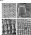
- the minimum feature resolution achieved in sintered structures in the x-y (horizontal) plane was 35 ⁇ m, and in the z-direction 1.2 ⁇ m, the smallest reported feature resolution to-date, as shown in Figure 3 .
- the maximum height of structures was approx. 300 ⁇ m and the tops of the pillars were concave due to a mild 'coffee staining' effect.
- the NiO was reduced to Ni at 670 °C in a 25-75 H 2 -He gas atmosphere for 2 hours after being heated at 4 °C min -1 in a pure He atmosphere (Elite Thermal Systems Ltd., UK). After reduction, the cell was progressively heated to the operating temperatures (718, 764 and 809 °C) monitored by a K-type thermocouple.
- the operational gas feed molar compositions were 9:1 CO 2 :CO with 40 ml min -1 total flow rate, controlled by an automated mass-flow controller (Bronkhorst, UK), as were all gas flow rates.
- the oxygen electrode electroser anode was operated in static air.
- Ni-YSZ cathode gaseous product composition was measured using on-line mass-spectrometry (Genesys 200D, ESS Ltd, UK) to determine the charge yield of the cell.
- Figure 6 shows the shrinkage behaviour of the individual constituent powders and mixtures.
- NiO and YSZ are inherently mismatched in their sintering behaviour.
- the final shrinkage of the NiO-YSZ substrate could be tailored to match that of a printed YSZ layer. This prevented stresses during sintering and enabled a flat, crack-free NiO-YSZ
- the printed YSZ electrolyte phase was dense, crack-free and adhered well to the Ni-YSZ substrate ( Figure 7 ), whereas low density is a commonly reported limitation of inkjet printing. After sintering, the total thickness of the printed electrolyte phase was about 23 ⁇ m, corresponding to about 2 ⁇ m for each of the 12 printed layers; hence, there is scope for decreasing the electrolyte phase thickness, without compromising gas-tightness.
- the open circuit potential differences were measured as 0.88 to 0.84 V at 718 °C and 809 °C, respectively, which were close to the theoretically calculated values.
- Current densities achieved at the thermo-neutral potential difference (ca. 1.5 V) were between -0.35 and - 0.78 A cm -2 in the investigated temperature range ( Figure 8 ). Faradaic efficiencies / charge yields of 100 % were confirmed by mass spectrometric concentration measurements of CO 2 reduced and CO produced. The maximum CO 2 conversion achieved was about 20 % resulting in a CO to CO 2 ratio of 3:7. Hence, coking was not expected to occur, as the CO equilibrium fraction for the Boudouard reaction is 0.7-0.91.
- planar and 3D microstructures may be fabricated by drop-on-demand, piezoelectric inkjet printing.
- Five aqueous YSZ-based inks with differing solids loading, binding polymer concentration, and particle size were formulated, and planar structures of each were printed. Cracking was mitigated by maximizing particle size and minimizing polymeric binder concentration, which created depletion potentials that aggregated the metal oxide particles, decreasing their packing density, and hence increasing their ability to avoid cracking, in printed structures.
- Micro-pillar arrays and square lattices were printed subsequently with the optimal ink formulation, resulting in crack-free microstructures with a minimum feature resolution of 35 ⁇ m in the horizontal plane.
- the mass-specific surface area of the particles was determined by BET analysis (N 2 adsorption) as 10.24 m 2 g -1 using a Micrometrics 3Flex BET instrument (Canada), and this was used to calculate the aluminon concentration with respect to LSM particle surface area.
- Each solution was ultrasonicated directly with a probe for 1-2 minutes.
- To measure zeta potential a droplet of each solution was added to a plastic, disposable cuvette filled with deionised water at pH 9.5 and KCI concentration 10 mM, and shaken to homogenise the contents. Seven measurements were then taken, and the average of each was taken as the zeta potential.
- the zeta potentials for the compositions comprising LSM particles and varying concentrations of aluminon as electrostatic dispersant are shown in Figure 10 .
- the error bars of the points in the graph are the standard deviation of the 7 measurements.
- CGO zeta potential data 6 solutions were made by dispersing CGO at different concentrations in deionised water with a KCI concentration of 10 mM. Dispex A40 (Ciba-BASF) was added at different area-specific concentration. CGO was dispersed by ultrasonicating each dispersion for 1-2 minutes. The compositions of the 6 solutions are shown in Table 3, and zeta potentials were measured using the same procedure as set out in Example 5. The mass-specific surface area of CGO (Ce 0.9 Gd 0.1 O 1.95 , Fuel Cell Materials, USA) was measured as 13.77 m 2 g -1 by BET measurements with N 2 adsorption.
- Figure 11 shows (a) the Zeta potential of CGO (solid circular markers corresponding to top horizontal axis) and LSCF (solid triangular markers) particles dispersed in water, with different dispersant concentrations: Dispex A40 (solid circular markers), Dispex Ultra FA 4416 (no-fill markers) and Duramax D3005 (solid triangular and diamond markers); and (b) particle size distribution of the filtered CGO (dotted), LSCF (solid), and CGO-LSCF aqueous inks in intensity (-•-) and volume (---) counts.
- CGO solid circular markers corresponding to top horizontal axis
- LSCF solid triangular markers
- Particle size distributions were measured by a dynamic light scattering technique. Using the most stable CGO and LSCF dispersions, defined as by having the zeta potential with the greatest magnitude, were diluted with deionised water to a sufficiently low concentration that light could pass through them. Measurements were taken at 25 °C.
- Figure 11c shows viscosity - shear relationship for CGO (circles), LSCF (crosses) and CGO-LSCF (diamonds) ink compositions.
- the particles were dispersed at the optimum concentration with the most effective dispersant, which were:
- the CGO dispersion was centrifuged at a relative centrifugal force (RCF) of 1,300 for 1 minute, and subsequently filtered with a syringe filter (DISMIC-25CS, Toya Roshi, Japan) to remove particles > 800 nm in diameter.
- Viscosity ( ⁇ ) and surface tension ( ⁇ ) were adjusted, respectively, by addition of 25 mg cm -3 polyethylene glycol) (Sigma Aldrich, USA) and 0.2 mg cm -3 Natsurf 265 (Croda, UK).
- the final solids loading, density ( ⁇ ), ⁇ , and ⁇ were 13 wt%, 1.148 g cm -3 , 4.95 mPa s ( Figure 11c using a Brookfield DV-E Viscometer (Brookhaven, USA)) and 28 mN m, respectively.
- the resulting Oh -1 number was 8.3.
- the LSCF dispersion was centrifuged at 1300 RCF for 1 minute, and filtered to remove particles > 800 nm in diameter. 10 mg cm -3 PEG 35000 and 0.2 mg cm -3 Natsurf 265 were added, to adjust viscosity and surface tension, respectively. The resulting solid loading, ⁇ , ⁇ , and ⁇ were 13 wt%, 1.15 g cm -3 , 8.0 mPa s ( Figure 11c ), and 28 mN m, respectively. The resulting Oh -1 number was 5.1.
- CGO-LSCF in Figure 11c To create the composite ink (CGO-LSCF in Figure 11c ), volumes of the individual CGO and LSCF inks were mixed together in the appropriate amounts resulting in an ink that was 1:1 mass ratio CGO:LSCF.
Landscapes
- Chemical & Material Sciences (AREA)
- Engineering & Computer Science (AREA)
- Chemical Kinetics & Catalysis (AREA)
- Electrochemistry (AREA)
- General Chemical & Material Sciences (AREA)
- Manufacturing & Machinery (AREA)
- Materials Engineering (AREA)
- Life Sciences & Earth Sciences (AREA)
- Sustainable Development (AREA)
- Sustainable Energy (AREA)
- Physics & Mathematics (AREA)
- Thermal Sciences (AREA)
- Wood Science & Technology (AREA)
- Organic Chemistry (AREA)
- Inks, Pencil-Leads, Or Crayons (AREA)
Claims (13)
- Wässrige Tintenzusammensetzung umfassend:ein wässriges Lösungsmittel;Partikel umfassend Yttriumoxid-stabilisiertes Zirkoniumdioxid (YSZ), Gadolinium-dotiertes Cerdioxid (GDC) oder Gemische davon;ein Dispergiermittel, wobei das Dispergiermittel ein elektrostatisches Dispergiermittel ist und in einer Menge von 0,1 bis 1 mg m-2 der Oberfläche der Partikel vorhanden ist;ein polymeres Bindemittel; undein nichtionisches Tensid.
- Wässrige Tintenzusammensetzung gemäß einem der vorstehenden Ansprüche, wobei die Partikel Yttriumoxid-stabilisiertes Zirkoniumdioxid (YSZ) umfassen, wobei die Partikel gegebenenfalls im Wesentlichen aus YSZ bestehen; wobei die Partikel gegebenenfalls Partikel von 8-mol-%-Yttriumoxid-stabilisiertem Zirkoniumdioxid umfassen.
- Wässrige Tintenzusammensetzung gemäß einem der vorstehenden Ansprüche, wobei die Partikel einen mittleren Partikeldurchmesser von 1000 nm oder weniger, gegebenenfalls 100 bis 800 nm, gegebenenfalls 100 bis 700 nm, aufweisen.
- Wässrige Tintenzusammensetzung gemäß einem der vorstehenden Ansprüche, wobei das Dispergiermittel ist:i) ein Salz einer Carbonsäure, gegebenenfalls ein Ammoniumsalz einer Carbonsäure, und/oderii) ein Salz eines Acrylpolymers.
- Wässrige Tintenzusammensetzung gemäß einem der vorstehenden Ansprüche, wobei das elektrostatische Dispergiermittel in einer Menge von 0,2 bis 0,8 mg m-2 der Oberfläche der Partikel vorhanden ist, gegebenenfalls wobei das elektrostatische Dispergiermittel ein Salz eines Acrylpolymers ist.
- Wässrige Tintenzusammensetzung gemäß einem der vorstehenden Ansprüche, wobei:a) das polymere Bindemittel ein Polyether ist; und/oderb) das polymere Bindemittel Polyethylenglycol ist, gegebenenfalls Polyethylenglycol mit einem anzahlgemittelten Molekulargewicht von 25000 bis 50000 Da; und/oderc) das nichtionische Tensid ein Alkoholalkoxylat-Tensid ist, gegebenenfalls ein Alkoholethoxylat-Tensid; und/oderd) das wässrige Lösungsmittel wenigstens 95 % Wasser umfasst; und/odere) die wässrige Tintenzusammensetzung einen Feststoffgehalt von 1 bis 50 Gew.-%, gegebenenfalls von 3 bis 30 Gew.-%, aufweist; und/oderf) das polymere Bindemittel in der wässrigen Tintenzusammensetzung in einer Konzentration von 10 bis 50 mg cm-3, gegebenenfalls 20 bis 40 mg cm-3 vorhanden ist; und/oderg) das nichtionische Tensid in der wässrigen Tintenzusammensetzung in einer Konzentration von 0,1 bis 0,5 mg cm-3, gegebenenfalls 0,2 mg cm-3, vorhanden ist.
- Wässrige Tintenzusammensetzung gemäß einem der vorstehenden Ansprüche mit:a) einer dynamischen Viskosität von 2 bis 20 mPa s, gemessen bei etwa 20 °C und etwa 1 Atmosphäre, gegebenenfalls 4 bis 15 mPa s; und/oderb) einer Druckbarkeitskennzahl, der dimensionslosen inversen Ohnesorge-Zahl (Oh-1), gemessen gemäß der Beschreibung, von 1 bis 14, gegebenenfalls 4,5 bis 10, gegebenenfalls 8,5 bis 9,5; und/oderc) einer kritischen Rissbildungsdicke, gemessen gemäß der Beschreibung, von wenigstens 10 µm, gegebenenfalls wenigstens 15 µm.
- Verfahren zur Herstellung einer wässrigen Tintenzusammensetzung gemäß einem der vorstehenden Ansprüche, umfassend die Schritte:(a) Bereitstellen eines wässrigen Lösungsmittels und Zugeben eines Dispergiermittels zu dem wässrigen Lösungsmittel;(b) Dispergieren von Partikeln, die Yttriumoxid-stabilisiertes Zirkoniumdioxid (YSZ) oder Gadolinium-dotiertes Cerdioxid (GDC) oder Gemische davon umfassen, in dem wässrigen Lösungsmittel; und(c) Zugeben eines polymeren Bindemittels und eines nichtionischen Tensids zu der wässrigen Dispersion.
- Verfahren gemäß Anspruch 8, wobei:a) Schritt (b) nach Schritt (a) durchgeführt wird; und/oderb) das Verfahren ferner den Schritt des Konzentrierens der wässrigen Dispersion durch Entfernen des wässrigen Lösungsmittels vor Zugeben des polymeren Bindemittels und des nichtionischen Tensids umfasst; und/oderc) die Partikel durch Ultraschallbehandlung in dem wässrigen Lösungsmittel dispergiert werden; und/oderd) das Verfahren ferner den Schritt des Schmälermachens der Partikelgrößenverteilung nach Dispergieren der Partikel in dem wässrigen Lösungsmittel umfasst.
- Verwendung der wässrigen Tintenzusammensetzung gemäß einem der Ansprüche 1 bis 7 als eine Tinte zum:a) 3D-Drucken, gegebenenfalls 3D-Tintenstrahldrucken; und/oderb) Bedrucken der Elektrolytphase oder einer Elektrode einer elektrochemischen Festoxidvorrichtung, gegebenenfalls eines Reaktors, gegebenenfalls einer Festoxid-Brennstoffzelle oder eines Festoxid-Elektrolyseurs.
- Verfahren zur Herstellung eines bedruckten Gegenstands, umfassend die Schritte:(a) Bereitstellen eines Substrats;(b) Drucken der wässrigen Tintenzusammensetzung gemäß einem der Ansprüche 1 bis 7 auf das Substrat, um einen bedruckten Gegenstand zu bilden; gegebenenfalls(c) Trocknen des bedruckten Gegenstands; und gegebenenfalls(d) Wärmebehandeln des bedruckten Gegenstands.
- Verfahren gemäß Anspruch 11, wobei:a) das Verfahren ferner den Schritt des Herstellens einer wässrigen Tintenzusammensetzung gemäß einem der Ansprüche 1 bis 7 vor Schritt (b) umfasst; und/oderb) die Partikel einen mittleren Partikeldurchmesser von 1000 nm oder weniger aufweisen und/oder eine obere Partikelgrößengrenze von 2 % des Durchmessers der zum Drucken der wässrigen Tintenzusammensetzung verwendeten Druckkopfdüsen aufweisen; gegebenenfalls einen mittleren Partikeldurchmesser von 100 bis 800 nm aufweisen; und/oderc) der Schritt des Druckens der wässrigen Tintenzusammensetzung Drucken einer Schicht auf das Substrat mit einer Dicke von 1 bis 500 µm umfasst; und/oderd) der Schritt des Druckens der wässrigen Tintenzusammensetzung Drucken einer 3D-Mikrostruktur umfasst; und/odere) das Substrat eine Elektrode in einer Festoxid-Brennstoffzelle oder einem Festoxid-Elektrolyseur ist.
- Verfahren zur Herstellung einer elektrochemischen Festoxidvorrichtung umfassend den Schritt des Druckens einer wässrigen Tintenzusammensetzung gemäß einem der Ansprüche 1 bis 7 oder wie hergestellt durch ein Verfahren gemäß einem der Ansprüche 11 bis 12, gegebenenfalls wobei die elektrochemische Festoxidvorrichtung eine Festoxid-Brennstoffzelle oder ein Festoxid-Elektrolyseur ist.
Applications Claiming Priority (2)
| Application Number | Priority Date | Filing Date | Title |
|---|---|---|---|
| GBGB1610925.8A GB201610925D0 (en) | 2016-06-22 | 2016-06-22 | Aqueous ink compositions |
| PCT/GB2017/051819 WO2017221010A1 (en) | 2016-06-22 | 2017-06-21 | Aqueous ink compositions |
Publications (3)
| Publication Number | Publication Date |
|---|---|
| EP3476002A1 EP3476002A1 (de) | 2019-05-01 |
| EP3476002C0 EP3476002C0 (de) | 2024-02-14 |
| EP3476002B1 true EP3476002B1 (de) | 2024-02-14 |
Family
ID=56895182
Family Applications (1)
| Application Number | Title | Priority Date | Filing Date |
|---|---|---|---|
| EP17734419.9A Active EP3476002B1 (de) | 2016-06-22 | 2017-06-21 | Wässrige tintenzusammensetzungen |
Country Status (4)
| Country | Link |
|---|---|
| US (1) | US10978717B2 (de) |
| EP (1) | EP3476002B1 (de) |
| GB (1) | GB201610925D0 (de) |
| WO (1) | WO2017221010A1 (de) |
Families Citing this family (16)
| Publication number | Priority date | Publication date | Assignee | Title |
|---|---|---|---|---|
| KR102092163B1 (ko) * | 2018-04-18 | 2020-03-23 | 가천대학교 산학협력단 | 금속산화물 나노입자 잉크 조성물, 금속산화물 나노입자 잉크 조성물의 제조방법 및 금속산화물 나노입자 잉크 조성물을 이용한 도전층 패턴 형성 방법 |
| CZ308412B6 (cs) * | 2018-05-14 | 2020-08-05 | Peter Knobloch | Pojivový materiál pro polygrafickou tiskovou hlavu pro 3D tisk |
| CN109192995A (zh) * | 2018-09-06 | 2019-01-11 | 深圳大学 | 一种喷墨3d打印制造固体氧化物燃料电池电极的方法 |
| US11611097B2 (en) | 2018-11-06 | 2023-03-21 | Utility Global, Inc. | Method of making an electrochemical reactor via sintering inorganic dry particles |
| US11603324B2 (en) | 2018-11-06 | 2023-03-14 | Utility Global, Inc. | Channeled electrodes and method of making |
| EP3877180A4 (de) | 2018-11-06 | 2022-12-14 | Utility Global, Inc. | Verfahren und system zur herstellung einer brennstoffzelle |
| US11539053B2 (en) | 2018-11-12 | 2022-12-27 | Utility Global, Inc. | Method of making copper electrode |
| US11761100B2 (en) | 2018-11-06 | 2023-09-19 | Utility Global, Inc. | Electrochemical device and method of making |
| WO2020102140A1 (en) * | 2018-11-12 | 2020-05-22 | Utility Global, Inc. | Manufacturing method with particle size control |
| ES2852058B2 (es) * | 2020-03-04 | 2022-02-25 | Kerionics S L | Procedimiento para la fabricacion de una membrana de separacion de gases |
| DE212022000192U1 (de) | 2021-05-04 | 2024-02-20 | Federal-Mogul Ignition Gmbh | Zündkerzenelektrode |
| EP4143266B1 (de) * | 2021-07-13 | 2023-11-01 | Sun Chemical Corporation | Stabile tintenstrahldispersionen und tinten |
| DE102023107904A1 (de) | 2022-03-29 | 2023-10-05 | Federal-Mogul Ignition Gmbh | Zündkerze, zündkerzenelektrode und verfahren zur herstellung derselben |
| US11837852B1 (en) | 2022-07-27 | 2023-12-05 | Federal-Mogul Ignition Gmbh | Spark plug electrode with electrode tip directly thermally coupled to heat dissipating core and method of manufacturing the same |
| FR3160818A1 (fr) * | 2024-03-26 | 2025-10-03 | Genvia | Procédé de fabrication d’un contact électrique en Lanthane Strontium Manganite sur un substrat |
| US12191637B1 (en) | 2024-06-14 | 2025-01-07 | Federal-Mogul Ignition Gmbh | Spark plug with cooling features and method of manufacturing the same |
Family Cites Families (16)
| Publication number | Priority date | Publication date | Assignee | Title |
|---|---|---|---|---|
| US6646024B2 (en) * | 1999-12-14 | 2003-11-11 | Lexmark International, Inc. | Ink compositions |
| US6803138B2 (en) | 2001-07-02 | 2004-10-12 | Nextech Materials, Ltd. | Ceramic electrolyte coating methods |
| US20050282928A1 (en) * | 2004-06-21 | 2005-12-22 | Tyau-Jeen Lin | Ink jet ink |
| EP1820828B1 (de) * | 2006-02-15 | 2012-01-04 | Canon Kabushiki Kaisha | Wässrige Tinte, Tintenstrahlaufzeichnungsverfahren, Tintenpatrone, Aufzeichnungseinheit und Tintenstrahlaufzeichnungsvorrichtung |
| US8659158B2 (en) * | 2006-08-16 | 2014-02-25 | Funai Electric Co., Ltd. | Thermally inkjettable acrylic dielectric ink formulation and process |
| US8404160B2 (en) * | 2007-05-18 | 2013-03-26 | Applied Nanotech Holdings, Inc. | Metallic ink |
| US8940821B2 (en) * | 2007-12-27 | 2015-01-27 | Eastman Kodak Company | Inks for high speed durable inkjet printing |
| KR101475520B1 (ko) * | 2008-01-14 | 2014-12-23 | 삼성전자주식회사 | 잉크젯 프린트용 양자점 잉크 조성물 및 그를 이용한전자소자 |
| KR101494435B1 (ko) | 2008-01-15 | 2015-02-23 | 삼성전자주식회사 | 전극, 리튬 전지, 전극 제조 방법 및 전극 코팅용 조성물 |
| JP2010229197A (ja) | 2009-03-26 | 2010-10-14 | Seiko Epson Corp | 耐水化アルミニウム顔料分散液の製造方法、耐水化アルミニウム顔料およびそれを含有する水性インク組成物 |
| US8348411B2 (en) * | 2009-09-30 | 2013-01-08 | Eastman Kodak Company | Pigment based inks for reliable high speed inkjet printing |
| US8430494B2 (en) * | 2010-10-29 | 2013-04-30 | Hewlett-Packard Development Company, L.P. | Ink forming method |
| GB2490869A (en) * | 2011-05-09 | 2012-11-21 | Univ Birmingham | Cathode ink |
| US8652707B2 (en) | 2011-09-01 | 2014-02-18 | Watt Fuel Cell Corp. | Process for producing tubular ceramic structures of non-circular cross section |
| KR101272036B1 (ko) | 2011-10-31 | 2013-06-07 | 한양대학교 산학협력단 | 세라믹 과립을 포함하는 고체산화물 연료전지 및 이의 제조방법 |
| KR101698941B1 (ko) * | 2012-04-24 | 2017-01-23 | 휴렛-팩커드 디벨롭먼트 컴퍼니, 엘.피. | 잉크젯 잉크 |
-
2016
- 2016-06-22 GB GBGB1610925.8A patent/GB201610925D0/en not_active Ceased
-
2017
- 2017-06-21 US US16/312,240 patent/US10978717B2/en active Active
- 2017-06-21 EP EP17734419.9A patent/EP3476002B1/de active Active
- 2017-06-21 WO PCT/GB2017/051819 patent/WO2017221010A1/en not_active Ceased
Also Published As
| Publication number | Publication date |
|---|---|
| GB201610925D0 (en) | 2016-08-03 |
| EP3476002A1 (de) | 2019-05-01 |
| EP3476002C0 (de) | 2024-02-14 |
| US10978717B2 (en) | 2021-04-13 |
| US20190207227A1 (en) | 2019-07-04 |
| WO2017221010A1 (en) | 2017-12-28 |
Similar Documents
| Publication | Publication Date | Title |
|---|---|---|
| US10978717B2 (en) | Aqueous ink compositions | |
| Farandos et al. | Three-dimensional inkjet printed solid oxide electrochemical reactors. I. Yttria-stabilized zirconia electrolyte | |
| Tomov et al. | Direct ceramic inkjet printing of yttria-stabilized zirconia electrolyte layers for anode-supported solid oxide fuel cells | |
| Shah et al. | Solid oxide fuel cell cathodes by infiltration of La0. 6Sr0. 4Co0. 2Fe0. 8O3− δ into Gd-Doped Ceria | |
| Çelikbilek et al. | Influence of sintering temperature on morphology and electrochemical performance of LSCF/GDC composite films as efficient cathode for SOFC | |
| EP2012381A1 (de) | Elektrodenelektrolyt-Verbundstoffpartikel für eine Brennstoffzelle und Herstellungsverfahren dafür | |
| Morales et al. | Processing of graded anode-supported micro-tubular SOFCs based on samaria-doped ceria via gel-casting and spray-coating | |
| US9005488B2 (en) | Aqueous ink for producing high-temperature electrochemical cell electrodes | |
| Farandos et al. | 3-D inkjet-printed solid oxide electrochemical reactors. II. LSM-YSZ electrodes | |
| Oh et al. | Thin film yttria-stabilized zirconia electrolyte for intermediate-temperature solid oxide fuel cells (IT-SOFCs) by chemical solution deposition | |
| Rahumi et al. | Nanostructured engineering of nickel cermet anode for solid oxide fuel cell using inkjet printing | |
| CN101659555A (zh) | 聚合无机-有机前体溶液和烧结膜 | |
| Kawale et al. | Inkjet 3D-printing of functional layers of solid oxide electrochemical reactors: a review | |
| Choi et al. | Low temperature preparation and characterization of solid oxide fuel cells on FeCr-based alloy support by aerosol deposition | |
| Sacanell et al. | Nanotubes of rare earth cobalt oxides for cathodes of intermediate-temperature solid oxide fuel cells | |
| Wang et al. | Inkjet printing infiltration of Ni-Gd: CeO2 anodes for low temperature solid oxide fuel cells | |
| CN104737342A (zh) | 由渗透产生的电极及方法 | |
| Fu et al. | Fabrication and Characterization of Anode‐Supported Low‐Temperature SOFC Based on Gd‐Doped Ceria Electrolyte | |
| Navarro et al. | Manufacturing of anode-supported tubular solid oxide fuel cells by a new shaping technique using aqueous gel-casting | |
| EP2166602B1 (de) | Herstellung einer Feststoffoxid-Brennstoffzellen-Membranelektrodenanordnung | |
| Zou et al. | Electrophoretic deposition of YSZ thin-film electrolyte for SOFCs utilizing electrostatic-steric stabilized suspensions obtained via high energy ball milling | |
| KR101394273B1 (ko) | 스펀지 구조를 갖는 다공성 박막, 이의 제조방법 및 이를 양극으로 포함하는 고체산화물 연료전지 | |
| CN108283023B (zh) | 燃料电池 | |
| KR102763799B1 (ko) | 페로브스카이트형 복합 산화물 분말 | |
| Zahir et al. | Wet Atomisation of Gd‐doped CeO2 Electrolyte Slurries for Intermediate Temperatures' Microtubular SOFC Applications |
Legal Events
| Date | Code | Title | Description |
|---|---|---|---|
| STAA | Information on the status of an ep patent application or granted ep patent |
Free format text: STATUS: UNKNOWN |
|
| STAA | Information on the status of an ep patent application or granted ep patent |
Free format text: STATUS: THE INTERNATIONAL PUBLICATION HAS BEEN MADE |
|
| PUAI | Public reference made under article 153(3) epc to a published international application that has entered the european phase |
Free format text: ORIGINAL CODE: 0009012 |
|
| STAA | Information on the status of an ep patent application or granted ep patent |
Free format text: STATUS: REQUEST FOR EXAMINATION WAS MADE |
|
| 17P | Request for examination filed |
Effective date: 20190116 |
|
| AK | Designated contracting states |
Kind code of ref document: A1 Designated state(s): AL AT BE BG CH CY CZ DE DK EE ES FI FR GB GR HR HU IE IS IT LI LT LU LV MC MK MT NL NO PL PT RO RS SE SI SK SM TR |
|
| AX | Request for extension of the european patent |
Extension state: BA ME |
|
| DAV | Request for validation of the european patent (deleted) | ||
| DAX | Request for extension of the european patent (deleted) | ||
| RAP1 | Party data changed (applicant data changed or rights of an application transferred) |
Owner name: IMPERIAL COLLEGE INNOVATIONS LIMITED |
|
| STAA | Information on the status of an ep patent application or granted ep patent |
Free format text: STATUS: EXAMINATION IS IN PROGRESS |
|
| 17Q | First examination report despatched |
Effective date: 20191126 |
|
| REG | Reference to a national code |
Ref country code: DE Ref legal event code: R079 Free format text: PREVIOUS MAIN CLASS: H01M0008125300 Ipc: H01M0008120000 Ref country code: DE Ref legal event code: R079 Ref document number: 602017079133 Country of ref document: DE Free format text: PREVIOUS MAIN CLASS: H01M0008125300 Ipc: H01M0008120000 |
|
| RIC1 | Information provided on ipc code assigned before grant |
Ipc: H01M 4/90 20060101ALI20230710BHEP Ipc: H01M 8/126 20160101ALI20230710BHEP Ipc: H01M 8/1253 20160101ALI20230710BHEP Ipc: H01M 4/88 20060101ALI20230710BHEP Ipc: H01M 8/12 20160101AFI20230710BHEP |
|
| GRAP | Despatch of communication of intention to grant a patent |
Free format text: ORIGINAL CODE: EPIDOSNIGR1 |
|
| STAA | Information on the status of an ep patent application or granted ep patent |
Free format text: STATUS: GRANT OF PATENT IS INTENDED |
|
| INTG | Intention to grant announced |
Effective date: 20230904 |
|
| GRAS | Grant fee paid |
Free format text: ORIGINAL CODE: EPIDOSNIGR3 |
|
| RAP1 | Party data changed (applicant data changed or rights of an application transferred) |
Owner name: FARANDOS, NICHOLAS |
|
| GRAA | (expected) grant |
Free format text: ORIGINAL CODE: 0009210 |
|
| STAA | Information on the status of an ep patent application or granted ep patent |
Free format text: STATUS: THE PATENT HAS BEEN GRANTED |
|
| AK | Designated contracting states |
Kind code of ref document: B1 Designated state(s): AL AT BE BG CH CY CZ DE DK EE ES FI FR GB GR HR HU IE IS IT LI LT LU LV MC MK MT NL NO PL PT RO RS SE SI SK SM TR |
|
| REG | Reference to a national code |
Ref country code: GB Ref legal event code: FG4D |
|
| REG | Reference to a national code |
Ref country code: CH Ref legal event code: EP |
|
| REG | Reference to a national code |
Ref country code: DE Ref legal event code: R096 Ref document number: 602017079133 Country of ref document: DE |
|
| REG | Reference to a national code |
Ref country code: IE Ref legal event code: FG4D |
|
| U01 | Request for unitary effect filed |
Effective date: 20240311 |
|
| U07 | Unitary effect registered |
Designated state(s): AT BE BG DE DK EE FI FR IT LT LU LV MT NL PT SE SI Effective date: 20240320 |
|
| U20 | Renewal fee for the european patent with unitary effect paid |
Year of fee payment: 8 Effective date: 20240515 |
|
| PG25 | Lapsed in a contracting state [announced via postgrant information from national office to epo] |
Ref country code: IS Free format text: LAPSE BECAUSE OF FAILURE TO SUBMIT A TRANSLATION OF THE DESCRIPTION OR TO PAY THE FEE WITHIN THE PRESCRIBED TIME-LIMIT Effective date: 20240614 |
|
| PG25 | Lapsed in a contracting state [announced via postgrant information from national office to epo] |
Ref country code: GR Free format text: LAPSE BECAUSE OF FAILURE TO SUBMIT A TRANSLATION OF THE DESCRIPTION OR TO PAY THE FEE WITHIN THE PRESCRIBED TIME-LIMIT Effective date: 20240515 |
|
| PG25 | Lapsed in a contracting state [announced via postgrant information from national office to epo] |
Ref country code: HR Free format text: LAPSE BECAUSE OF FAILURE TO SUBMIT A TRANSLATION OF THE DESCRIPTION OR TO PAY THE FEE WITHIN THE PRESCRIBED TIME-LIMIT Effective date: 20240214 Ref country code: RS Free format text: LAPSE BECAUSE OF FAILURE TO SUBMIT A TRANSLATION OF THE DESCRIPTION OR TO PAY THE FEE WITHIN THE PRESCRIBED TIME-LIMIT Effective date: 20240514 |
|
| PG25 | Lapsed in a contracting state [announced via postgrant information from national office to epo] |
Ref country code: ES Free format text: LAPSE BECAUSE OF FAILURE TO SUBMIT A TRANSLATION OF THE DESCRIPTION OR TO PAY THE FEE WITHIN THE PRESCRIBED TIME-LIMIT Effective date: 20240214 |
|
| PG25 | Lapsed in a contracting state [announced via postgrant information from national office to epo] |
Ref country code: RS Free format text: LAPSE BECAUSE OF FAILURE TO SUBMIT A TRANSLATION OF THE DESCRIPTION OR TO PAY THE FEE WITHIN THE PRESCRIBED TIME-LIMIT Effective date: 20240514 Ref country code: NO Free format text: LAPSE BECAUSE OF FAILURE TO SUBMIT A TRANSLATION OF THE DESCRIPTION OR TO PAY THE FEE WITHIN THE PRESCRIBED TIME-LIMIT Effective date: 20240514 Ref country code: IS Free format text: LAPSE BECAUSE OF FAILURE TO SUBMIT A TRANSLATION OF THE DESCRIPTION OR TO PAY THE FEE WITHIN THE PRESCRIBED TIME-LIMIT Effective date: 20240614 Ref country code: HR Free format text: LAPSE BECAUSE OF FAILURE TO SUBMIT A TRANSLATION OF THE DESCRIPTION OR TO PAY THE FEE WITHIN THE PRESCRIBED TIME-LIMIT Effective date: 20240214 Ref country code: GR Free format text: LAPSE BECAUSE OF FAILURE TO SUBMIT A TRANSLATION OF THE DESCRIPTION OR TO PAY THE FEE WITHIN THE PRESCRIBED TIME-LIMIT Effective date: 20240515 Ref country code: ES Free format text: LAPSE BECAUSE OF FAILURE TO SUBMIT A TRANSLATION OF THE DESCRIPTION OR TO PAY THE FEE WITHIN THE PRESCRIBED TIME-LIMIT Effective date: 20240214 |
|
| PG25 | Lapsed in a contracting state [announced via postgrant information from national office to epo] |
Ref country code: PL Free format text: LAPSE BECAUSE OF FAILURE TO SUBMIT A TRANSLATION OF THE DESCRIPTION OR TO PAY THE FEE WITHIN THE PRESCRIBED TIME-LIMIT Effective date: 20240214 |
|
| PG25 | Lapsed in a contracting state [announced via postgrant information from national office to epo] |
Ref country code: PL Free format text: LAPSE BECAUSE OF FAILURE TO SUBMIT A TRANSLATION OF THE DESCRIPTION OR TO PAY THE FEE WITHIN THE PRESCRIBED TIME-LIMIT Effective date: 20240214 |
|
| PG25 | Lapsed in a contracting state [announced via postgrant information from national office to epo] |
Ref country code: SM Free format text: LAPSE BECAUSE OF FAILURE TO SUBMIT A TRANSLATION OF THE DESCRIPTION OR TO PAY THE FEE WITHIN THE PRESCRIBED TIME-LIMIT Effective date: 20240214 |
|
| PG25 | Lapsed in a contracting state [announced via postgrant information from national office to epo] |
Ref country code: CZ Free format text: LAPSE BECAUSE OF FAILURE TO SUBMIT A TRANSLATION OF THE DESCRIPTION OR TO PAY THE FEE WITHIN THE PRESCRIBED TIME-LIMIT Effective date: 20240214 |
|
| PG25 | Lapsed in a contracting state [announced via postgrant information from national office to epo] |
Ref country code: SK Free format text: LAPSE BECAUSE OF FAILURE TO SUBMIT A TRANSLATION OF THE DESCRIPTION OR TO PAY THE FEE WITHIN THE PRESCRIBED TIME-LIMIT Effective date: 20240214 |
|
| PG25 | Lapsed in a contracting state [announced via postgrant information from national office to epo] |
Ref country code: SM Free format text: LAPSE BECAUSE OF FAILURE TO SUBMIT A TRANSLATION OF THE DESCRIPTION OR TO PAY THE FEE WITHIN THE PRESCRIBED TIME-LIMIT Effective date: 20240214 Ref country code: SK Free format text: LAPSE BECAUSE OF FAILURE TO SUBMIT A TRANSLATION OF THE DESCRIPTION OR TO PAY THE FEE WITHIN THE PRESCRIBED TIME-LIMIT Effective date: 20240214 Ref country code: RO Free format text: LAPSE BECAUSE OF FAILURE TO SUBMIT A TRANSLATION OF THE DESCRIPTION OR TO PAY THE FEE WITHIN THE PRESCRIBED TIME-LIMIT Effective date: 20240214 Ref country code: CZ Free format text: LAPSE BECAUSE OF FAILURE TO SUBMIT A TRANSLATION OF THE DESCRIPTION OR TO PAY THE FEE WITHIN THE PRESCRIBED TIME-LIMIT Effective date: 20240214 |
|
| REG | Reference to a national code |
Ref country code: DE Ref legal event code: R097 Ref document number: 602017079133 Country of ref document: DE |
|
| PLBE | No opposition filed within time limit |
Free format text: ORIGINAL CODE: 0009261 |
|
| STAA | Information on the status of an ep patent application or granted ep patent |
Free format text: STATUS: NO OPPOSITION FILED WITHIN TIME LIMIT |
|
| 26N | No opposition filed |
Effective date: 20241115 |
|
| PG25 | Lapsed in a contracting state [announced via postgrant information from national office to epo] |
Ref country code: MC Free format text: LAPSE BECAUSE OF FAILURE TO SUBMIT A TRANSLATION OF THE DESCRIPTION OR TO PAY THE FEE WITHIN THE PRESCRIBED TIME-LIMIT Effective date: 20240214 |
|
| PGFP | Annual fee paid to national office [announced via postgrant information from national office to epo] |
Ref country code: GB Payment date: 20250613 Year of fee payment: 9 |
|
| U20 | Renewal fee for the european patent with unitary effect paid |
Year of fee payment: 9 Effective date: 20250613 |
|
| PGFP | Annual fee paid to national office [announced via postgrant information from national office to epo] |
Ref country code: IE Payment date: 20250623 Year of fee payment: 9 |
|
| PGFP | Annual fee paid to national office [announced via postgrant information from national office to epo] |
Ref country code: CH Payment date: 20250701 Year of fee payment: 9 |
|
| PG25 | Lapsed in a contracting state [announced via postgrant information from national office to epo] |
Ref country code: CY Free format text: LAPSE BECAUSE OF FAILURE TO SUBMIT A TRANSLATION OF THE DESCRIPTION OR TO PAY THE FEE WITHIN THE PRESCRIBED TIME-LIMIT; INVALID AB INITIO Effective date: 20170621 |
|
| PG25 | Lapsed in a contracting state [announced via postgrant information from national office to epo] |
Ref country code: HU Free format text: LAPSE BECAUSE OF FAILURE TO SUBMIT A TRANSLATION OF THE DESCRIPTION OR TO PAY THE FEE WITHIN THE PRESCRIBED TIME-LIMIT; INVALID AB INITIO Effective date: 20170621 |