EP3475157B1 - A mooring connector - Google Patents
A mooring connector Download PDFInfo
- Publication number
- EP3475157B1 EP3475157B1 EP17748851.7A EP17748851A EP3475157B1 EP 3475157 B1 EP3475157 B1 EP 3475157B1 EP 17748851 A EP17748851 A EP 17748851A EP 3475157 B1 EP3475157 B1 EP 3475157B1
- Authority
- EP
- European Patent Office
- Prior art keywords
- connector
- optionally
- locking
- locking member
- locking element
- Prior art date
- Legal status (The legal status is an assumption and is not a legal conclusion. Google has not performed a legal analysis and makes no representation as to the accuracy of the status listed.)
- Active
Links
Images


Classifications
-
- B—PERFORMING OPERATIONS; TRANSPORTING
- B63—SHIPS OR OTHER WATERBORNE VESSELS; RELATED EQUIPMENT
- B63B—SHIPS OR OTHER WATERBORNE VESSELS; EQUIPMENT FOR SHIPPING
- B63B21/00—Tying-up; Shifting, towing, or pushing equipment; Anchoring
- B63B21/50—Anchoring arrangements or methods for special vessels, e.g. for floating drilling platforms or dredgers
-
- B—PERFORMING OPERATIONS; TRANSPORTING
- B63—SHIPS OR OTHER WATERBORNE VESSELS; RELATED EQUIPMENT
- B63B—SHIPS OR OTHER WATERBORNE VESSELS; EQUIPMENT FOR SHIPPING
- B63B21/00—Tying-up; Shifting, towing, or pushing equipment; Anchoring
-
- B—PERFORMING OPERATIONS; TRANSPORTING
- B63—SHIPS OR OTHER WATERBORNE VESSELS; RELATED EQUIPMENT
- B63B—SHIPS OR OTHER WATERBORNE VESSELS; EQUIPMENT FOR SHIPPING
- B63B21/00—Tying-up; Shifting, towing, or pushing equipment; Anchoring
- B63B21/04—Fastening or guiding equipment for chains, ropes, hawsers, or the like
-
- B—PERFORMING OPERATIONS; TRANSPORTING
- B63—SHIPS OR OTHER WATERBORNE VESSELS; RELATED EQUIPMENT
- B63B—SHIPS OR OTHER WATERBORNE VESSELS; EQUIPMENT FOR SHIPPING
- B63B21/00—Tying-up; Shifting, towing, or pushing equipment; Anchoring
- B63B21/50—Anchoring arrangements or methods for special vessels, e.g. for floating drilling platforms or dredgers
- B63B21/502—Anchoring arrangements or methods for special vessels, e.g. for floating drilling platforms or dredgers by means of tension legs
-
- E—FIXED CONSTRUCTIONS
- E21—EARTH OR ROCK DRILLING; MINING
- E21B—EARTH OR ROCK DRILLING; OBTAINING OIL, GAS, WATER, SOLUBLE OR MELTABLE MATERIALS OR A SLURRY OF MINERALS FROM WELLS
- E21B41/00—Equipment or details not covered by groups E21B15/00 - E21B40/00
- E21B41/10—Guide posts, e.g. releasable; Attaching guide lines to underwater guide bases
-
- F—MECHANICAL ENGINEERING; LIGHTING; HEATING; WEAPONS; BLASTING
- F16—ENGINEERING ELEMENTS AND UNITS; GENERAL MEASURES FOR PRODUCING AND MAINTAINING EFFECTIVE FUNCTIONING OF MACHINES OR INSTALLATIONS; THERMAL INSULATION IN GENERAL
- F16G—BELTS, CABLES, OR ROPES, PREDOMINANTLY USED FOR DRIVING PURPOSES; CHAINS; FITTINGS PREDOMINANTLY USED THEREFOR
- F16G11/00—Means for fastening cables or ropes to one another or to other objects; Caps or sleeves for fixing on cables or ropes
-
- F—MECHANICAL ENGINEERING; LIGHTING; HEATING; WEAPONS; BLASTING
- F16—ENGINEERING ELEMENTS AND UNITS; GENERAL MEASURES FOR PRODUCING AND MAINTAINING EFFECTIVE FUNCTIONING OF MACHINES OR INSTALLATIONS; THERMAL INSULATION IN GENERAL
- F16G—BELTS, CABLES, OR ROPES, PREDOMINANTLY USED FOR DRIVING PURPOSES; CHAINS; FITTINGS PREDOMINANTLY USED THEREFOR
- F16G11/00—Means for fastening cables or ropes to one another or to other objects; Caps or sleeves for fixing on cables or ropes
- F16G11/10—Quick-acting fastenings; Clamps holding in one direction only
- F16G11/105—Clamps holding in one direction only
- F16G11/108—Clamps holding in one direction only using a ball or a cylinder
-
- F—MECHANICAL ENGINEERING; LIGHTING; HEATING; WEAPONS; BLASTING
- F16—ENGINEERING ELEMENTS AND UNITS; GENERAL MEASURES FOR PRODUCING AND MAINTAINING EFFECTIVE FUNCTIONING OF MACHINES OR INSTALLATIONS; THERMAL INSULATION IN GENERAL
- F16G—BELTS, CABLES, OR ROPES, PREDOMINANTLY USED FOR DRIVING PURPOSES; CHAINS; FITTINGS PREDOMINANTLY USED THEREFOR
- F16G15/00—Chain couplings, Shackles; Chain joints; Chain links; Chain bushes
- F16G15/04—Quickly-detachable chain couplings; Shackles chain links with rapid junction means are classified according to the corresponding kind of chain
-
- B—PERFORMING OPERATIONS; TRANSPORTING
- B63—SHIPS OR OTHER WATERBORNE VESSELS; RELATED EQUIPMENT
- B63B—SHIPS OR OTHER WATERBORNE VESSELS; EQUIPMENT FOR SHIPPING
- B63B21/00—Tying-up; Shifting, towing, or pushing equipment; Anchoring
- B63B2021/003—Mooring or anchoring equipment, not otherwise provided for
-
- B—PERFORMING OPERATIONS; TRANSPORTING
- B63—SHIPS OR OTHER WATERBORNE VESSELS; RELATED EQUIPMENT
- B63B—SHIPS OR OTHER WATERBORNE VESSELS; EQUIPMENT FOR SHIPPING
- B63B21/00—Tying-up; Shifting, towing, or pushing equipment; Anchoring
- B63B2021/003—Mooring or anchoring equipment, not otherwise provided for
- B63B2021/004—Quick release elements in mooring connections
Definitions
- the present invention relates to a connector for use in mooring or lifting, and in particular to a mooring connector configured to release under load from its locking with a complementary connector.
- mooring connectors are used to connect drilling rig mooring lines together to secure a drilling rig to the seabed.
- a secured drilling rig may need to be released and moved to avoid inclement weather such as a storm.
- Release under load mooring connectors are designed for this purpose and are therefore configured to function when the connected mooring lines are under tension and a load is applied to the mooring connector.
- a problem with existing mooring connectors is that they can be irreparably damaged if released from one another under too great a load.
- release under load mooring connectors have a specified safe limit at which they should be released when under a load.
- this limit is about 30% of the minimum break load (MBL), which is the minimum load at which damage will be caused to the mooring connector.
- US4799816 discloses a disconnectable connection device for a guide line connecting a floating support such as a barge, to an undersea installation having a guide post sleeve.
- US/2014110129 discloses a disconnect apparatus including a lower housing and a retainer sleeve disposed within the lower housing and configured to move longitudinally within the lower housing.
- EP1710450 discloses a gripping device which serves as a pipeline recovery tool or mooring connector.
- GB2424684 discloses connectors for use with underwater elongate members such as umbilicals, pipes, risers and the like.
- Embodiments of the present invention seek to provide a connector, particularly a mooring connector, that may be safely released from a complementary connector when under a greater load than connectors of the prior art. This delays or eliminates the need for mooring lines to be released and thus enables increased utilisation of the moored equipment.
- a connector for use in mooring or lifting the connector being adapted for release under load from a complementary connector, the connector comprising:
- the present invention is configured to use a load applied to a connector that could otherwise damage the connector to assist in its unlocking from a complementary connector, when the connector and complementary connector are released from one another whilst under the load. Specifically, this reduces the likelihood of a connector being damaged when released under load. It is in a state of partial release that a connector is likely to be damaged when released under load, when the load carried by the connector may be supported by partially engaged components and so the load is supported by a reduced surface area or mass of material.
- load applied to the connector when in a partially unlocked state causes the connector to rapidly move into an unlocked state. This allows the complementary connector to separate without the potentially damaging load being taken up by the connector in a partially unlocked state.
- the present invention therefore provides a connector that can be safely released from its locking with a complementary connector whilst the connector and the complementary connector are under a high load pulling them apart.
- embodiments of the present invention can be released from their complementary connectors when the load is a high percentage of their minimum break load (MBL), such as up to 75%, compared to conventional connectors that must be released at 30% of their MBL to avoid damage.
- MBL minimum break load
- the present invention can allow an operator to delay release of the drilling rig under inclement weather conditions, allowing the weather to get worse and increasing the tension across the mooring line, in order to more accurately determine if release is necessary.
- the connector may be a male connector.
- the complementary connector may be a female connector.
- the body may be elongate, defining a longitudinal axis between its ends.
- the body may be cylindrical and/or hollow.
- the body may comprise a front end for steering towards a complementary connector.
- the front end may be frustoconical.
- the front end may have a chamfered rim for assisting in insertion into the complementary connector.
- the body may comprise an aperture, one or more apertures or a plurality of apertures.
- the or each aperture may be formed in an outer surface, for example and outer cylindrical surface, of the body which may form part of a ball cage.
- Each aperture may be a substantially cylindrical bore.
- Each aperture may be obliquely angled towards the front end of the body, from its radially inward region to its radially outward region. That is to say, the angle between the axis of the or each aperture and the longitudinal axis of the connector body may be acute. In embodiments the angle is in the range 60 to 70 degrees.
- each aperture may be angled perpendicular to the longitudinal axis of the body.
- Each aperture may extend from an inside surface of the body to an outside surface of the body.
- Each aperture may be for receiving and at least partially housing a locking element.
- Each aperture may comprise a portion having a slight reduction in diameter of the aperture at a radially outer region, thereby preventing a locking element passing radially out through the aperture.
- the apertures may be circumferentially substantially equidistantly spaced apart.
- the apertures may be arranged in at least one or multiple rows spaced circumferentially around the connector. Each row of apertures may be circumferentially in line with the next row. Each row of apertures may be circumferentially offset from the next row.
- the locking member may be housed within the connector.
- the connector may comprise a biasing means for biasing the locking member from its fully unlocked position or partially unlocked position towards its fully locked position.
- the biasing means may be resilient and may be a spring.
- the locking member may be formed from a metal.
- the locking member may comprise a pocket, one or more pockets or a plurality of pockets, formed in an outer surface of the locking member.
- Each pocket in the locking member may correspond to an aperture in the connector body.
- Each pocket may be sized and/or shaped for partially housing or receiving a locking element, which may be rounded.
- each pocket may be partially hemispherical.
- the pockets may be circumferentially equidistantly spaced apart.
- the pockets may be arranged in at least one or multiple rows spaced circumferentially around the locking member. Each row of pockets may be circumferentially in line with the next row. Each row of pockets may be circumferentially offset from the next row.
- Each pocket may comprise a front edge and or a pocket ramp portion. The front edge and or pocket ramp portion may be formed at an angle relative to its corresponding aperture and/or relative to the locking member so that a locking member received into the pocket urges the locking member from its partially unlocked position towards its fully unlocked position.
- the movement means may be operable to move the locking member axially relative to the longitudinal axis of the connector.
- the movement means may comprise an actuator such as a hydraulic actuator.
- the hydraulic actuator may comprise a pump or accumulator that is fluidly connected to a cylinder and piston arrangement.
- the cylinder and piston arrangement may be configured so that axial movement of the piston moves the locking member axially relative to the longitudinal axis of the connector.
- the cylinder may thus be fixed in position whilst the piston may be free to move axially, or vice versa.
- the movement means may be configured to be remotely operated and controlled, for example using an acoustic or radio signal.
- the connector may comprise one locking element or one or more locking elements. For example, there may be at least 3, 6, 9 or 12 locking elements.
- the locking elements may be spherical or rolling elements such as balls, cylinders, or the like.
- the locking elements are preferably locking balls.
- the locking elements may be formed from a metal.
- the connector may comprise a connection means or connector for connection to a cable, line, or the like.
- each locking element When the locking member is in its fully locked position, the locking member may be spaced away from the front end of the body of the connector, each locking element may be positively urged radially outwards of the connector by the locking member and housed partially in its aperture such that an edge of each locking element protrudes from its aperture for locking the connector with a complementary connector.
- each locking element When the locking member is in its fully unlocked position, the locking member may be near to or adjacent the front end of the body of the connector, each locking element may float freely of the locking member and may be received in its corresponding pocket and housed partially in its aperture such that no edge of the locking element is pushed to protrude from the aperture for unlocking the connector from a complementary connector.
- each locking element When the locking member is in its partially unlocked position, each locking element may be positively urged radially outwards of the connector by the locking element and housed partially in its aperture such that an edge of each locking element protrudes from the aperture for locking the connector with a complementary connector, and a front edge of each pocket may have passed beyond a centre line of each locking element.
- a connector assembly comprising a connector according to the first aspect of the invention; and a complementary connector.
- the connector of the connector assembly according to the second aspect of the invention may thus comprise any or all features of the connector according to the first aspect of the invention.
- the complementary connector may comprise a body.
- the body may be elongate, defining a longitudinal axis between its ends.
- the body may be cylindrical and/or hollow.
- the body may have an opening in one of its ends that defines an axially extending bore.
- the body may comprise end portions at its opening that are angled for guiding a connector into the opening so that the connector can engage with and lock to the complementary connector.
- the complementary connector may comprise a groove, one or more grooves or a plurality of grooves, formed in an inner surface of the complementary connector body.
- the grooves may be arranged circumferentially on the complementary connector.
- Each groove in the complementary connector body may correspond to one or more apertures in the connector body.
- Each groove may be sized and/or shaped for partially housing or receiving at least one locking element, which may be rounded.
- each groove may be substantially partially hemispherical.
- the width of each groove may be greater than the diameter of its corresponding locking element.
- Each groove may comprise a ramp portion formed at an angle relative to the apertures and/or the locking member for guiding a locking element in and out of the groove.
- the grooves may be circumferentially equidistantly spaced apart.
- the grooves may be arranged in at least one or multiple rows spaced circumferentially around the complementary connector. Each row of grooves may be circumferentially in line with the next row. Each row of grooves may be circumfer
- each groove may be arranged so that a load urging a locked connector and complimentary connector apart causes a radial force to be applied to a locking element received in the groove, urging it towards the connector.
- the complimentary connector may have a longitudinal axis and the ramp portion may extends at an angle to the longitudinal axis in the range 30 to 40 degrees.
- the complementary connector may comprise a connection means or connector for connection to a cable, line, or the like.
- FIG. 1 there is shown a connector assembly comprising a male connector 1 engaged with a complementary female connector 2.
- the complementary connector 2 comprises a substantially cylindrical body 27 having an opening 28 that defines an axially extending bore 20.
- An end portion 9 of the body 27 is angled so as to act as a guide to steer a frustoconical front end 22 of the connector 1 into the bore 20 so that the connector 1 can engage with and lock to the complementary connector 2. In this position, the front end 22 of the connector 1 abuts with the base of the bore 20 to prevent over-insertion.
- the connector 1 comprises a substantially cylindrical body 10 having a frustoconical front end 22 and defining an axially extending internal bore 6.
- the front end 22 has a chamfered rim 30 to assist in insertion of the connector 1 into the complementary connector 2.
- the bore 6 of the connector 1 and the bore 20 of the complementary connector 2 each (and together) have a defined longitudinal axis X due to their substantially cylindrical shape.
- the bore 6 houses a substantially cylindrical locking member 8 that has an end face 21 and contains an internal bore 19.
- the locking member 8 sits concentrically within the bore 6 of the body 10 so that the outer surface of its wall is adj acent the inner surface of the wall of the body 10.
- the locking member 8 is axially slidable within the bore 6, towards and away from the front end 22 of the body 10.
- the bore 6 of the locking member 8 houses a biasing means, in this case a helical spring 18, which biases the locking member 8 away from the front end 22 of the body 10, towards its fully locked position.
- Each aperture 5 is a substantially cylindrical bore that is obliquely angled towards the front edge 22 of the body 10, from its radially inward region to its radially outward region at an angle of between 60 and 70 degrees to the longitudinal axis of the connector.
- a locking element in this case a spherical locking ball 4, sits within each of the apertures 5 in the body 10.
- Each aperture 5 is sized and shaped so as to capture a locking ball 4 in such a way that a portion of the locking ball 4 can extend radially outward and inward from the aperture 5, but cannot fully escape radially outwardly from the aperture 5. This is achieved by a slight reduction in the diameter of the aperture 5 at its radially outer region.
- the apertures 5 allow the body 10 to act as a ball cage to restrict movement of the locking balls 4.
- the locking member 8 comprises a series of circumferentially equidistantly spaced pockets 17 in the outside surface of its wall.
- Each pocket 17 is part hemispherical or part semi-hemispherical so as to partially receive a locking ball 4, thus the diameter of each of the pockets 17 is greater than the diameter of its corresponding locking ball 4.
- Each pocket 17 is formed with a curved ramp portion 32 that leads to a flattened base portion 29.
- Each pocket 17 also has a front edge 31 adjacent the front (free) end of the connector.
- each locking ball 4 sits within a respective aperture 5 and the locking member 8 comprises an individual pocket 17 in respect of each locking ball 4.
- the locking balls 4 When the locking member 8 is in its fully locked position, the locking balls 4 are held radially outward by the locking member 8, by contact with the outer cylindrical surface of the locking member between the pockets 17, so that each locking ball 4 protrudes radially out of its aperture 5 (as shown in Figure 1 ). When the locking member 8 is in its fully unlocked position, the locking balls 4 may be partially received into their respective pocket 17 so that each locking ball 4 does not protrude radially out of its aperture 5 (as shown in Figures 2 and 3 ).
- the pocket ramp and edge portions 31, 32 are each formed at an effective angle with respect to the apertures 5 such that when the locking member 8 is in a partially unlocked position, a locking ball 4 being forced into its pocket 17 urges the locking member 8 towards its fully unlocked position.
- the connector 1 further comprises a hydraulic actuator 23 for pushing the locking member 8 towards the front end 22 of the body 10, against the biasing force provided by the spring 18.
- the hydraulic actuator 23 comprises an accumulator 11 held within the connector 1 by a bracket 24.
- the accumulator 11 is fluidly connected to a cylinder 15 and piston 16 arrangement.
- the cylinder 15 is fixed in position so that the piston 16 may move axially relative to the cylinder 15.
- the piston 16 abuts the locking member 8 such that axial movement of the piston 16 effects axial movement of the locking member 8 relative to the connector 1.
- the piston 16 is stepped so as to form a protrusion 25 that retains the piston 16 within the cylinder 15 by abutting against a similar stepped protrusion 26 on the cylinder 15.
- the accumulator 11 and the cylinder 15 are each fluidly connected to a reservoir.
- the accumulator 11 is also fluidly connected to an inlet connection to allow for supply of hydraulic fluid and the reservoir is fluidly connected to an outlet connection to allow for discharge of hydraulic fluid.
- the complementary connector 2 further comprises a series of circumferentially equidistantly spaced grooves 7 in the inside surface of its wall.
- Each groove 7 is substantially part hemispherical so as to partially receive the protruding edge of a locking ball 4.
- the diameter of each of the grooves 7 is greater than the diameter of its corresponding locking ball 4.
- Each groove 7 is formed with a ramp portion 12 that acts to guide a locking ball 4 out of the groove 7, as a result of separation of the connector and complimentary connector, when the locking ball 4 is permitted to recede back into its aperture 5 by the locking member 8 extending to its fully unlocked position.
- the ramp portions 12 are each formed at an effective angle with respect to the apertures 5 such that when an axial load is applied to separate the locked connector 1 from the complementary connector 2, friction between the surfaces of the groove 7 and the aperture 5 that a locking ball 4 is in contact with reduces but does not eliminate the radial inward load applied to the locking ball 4.
- the ramp portions lie at an angle to the longitudinal axis of the complimentary connector (which is substantially parallel to that of the connector when the two are engaged) in the range 30 to 40 degrees.
- the connector 1 and the complementary connector 2 each comprise a connection means 3, 13 for connection to a cable, line, or the like.
- a mooring line attached to a drilling rig or other vessel is connected to the connection means 3 on the complementary connector 2 and a mooring line attached to the seabed or another structure such as a buoy or turret (for example, not shown) is connected to the connection means 13 on the connector 1.
- the connector 1 and the complementary connector 2 when engaged with one another act as a mooring connector that connects the two mooring lines together, which secures the drilling rig to the seabed.
- the connector 1 is inserted into the opening 28 of the complementary connector 2. This unlocked but inserted position is shown in Figure 6 .
- the connector 1 is then pushed into the complementary connector 2 until the front edge 22 of the connector 1 abuts with the base of the opening 28 of the complementary connector 2 to prevent over-insertion.
- the hydraulic actuator 23 is activated to empty the cylinder 15 of hydraulic fluid so as to allow the piston 16 to retract into the cylinder 15 and to free the locking member 8 to move axially towards the hydraulic actuator 23.
- the spring 18 thus pushes the locking member 8 axially towards the hydraulic actuator 23, away from the complementary connector 2. This position of the locking member 8 is shown in Figure 2 .
- the connector 1 In normal use, the connector 1 remains locked to the complementary connector 2, securing the drilling rig to the seabed. However, during inclement weather, for example a storm, the mooring lines attached to the connection means 3, 13 may be placed under significant tension, which applies a load to the connector 1 and the complementary connector 2 that urges them to be pulled apart, out of their engagement with one another. Although the slopes and relative alignment of the grooves 7 in the complementary connector 2 and apertures 5 in the connector 1 are such that a component of radial force is applied to the locking balls 4, as the locking balls 4 are supported on the cylindrical outer surface of the locking member 8 they do not impart any axial force to the locking member 8.
- this load is supported by the locking balls 4 that are locking the connector 1 to the complementary connector 2.
- the connector 1 and complementary connector 2 are unlocked from one another by a user (as will be described) in order to avoid irreparable damage.
- the connector 1 and the complementary connector 2 may be disengaged from one another in order to move the drilling rig to a safe area if the inclement weather is predicted to get worse.
- the accumulator 11 of the hydraulic actuator 23 is activated, which draws hydraulic fluid from the input connection or reservoir and drives it into the cylinder 15.
- the hydraulic fluid forces the piston 16 to move axially relative to the cylinder 15, towards the front end 22 of the connector 1. Consequently, this movement pushes the locking member 8 to slide axially within the bore 6, relative to connector 1, against the biasing force provided by the spring 18 and towards the front end 22. Movement of the locking member 8 in this way is not affected by the load urging the connector 1 and complementary connector 2 apart.
- each pocket 17 begins to pass over its respective aperture 5 and locking ball 4.
- the locking balls 4 securing the connector 1 and the complementary connector 2 together are under load and being pushed out of the grooves 7 and towards the locking member 8 (and towards the longitudinal axis of the connector 1), but are retained in their apertures 5 by their contact with the front edges 31 of the pockets 17.
- each pocket 17 is only partially open and the locking balls 4 are still retained in their grooves 7.
- a component of the load applied to the locking balls 4 pushes them into the their corresponding pockets 17 in the locking member 8.
- the oblique angle of each aperture 5 assists in causing each locking ball 4 to roll on its groove ramp portion 12, out of its groove 7 and through its aperture 5.
- Each locking ball 4 is then forced into its corresponding pocket 17, where it initially contacts the front edge of the pocket before contacting the pocket ramp portion 32 and eventually coming to a rest on the flattened base portion 29 of the pocket 17.
- the locking member 8 When the locking member 8 is in its fully unlocked position, the locking balls 4 are retained in their pocket 17 and no longer protrude beyond the edge of their aperture 5. Thus, when the locking member 8 is in its fully unlocked position, the locking member 8 prevents the locking balls 4 from engaging with the complementary connector 2 (although it is possible that the locking balls 4 may still contact the complementary connector 2).
- the fully unlocked position of the locking member 8 is shown in Figures 5 and 6 .
- the connector 1 may be unlocked and removed from the complementary connector 2 by moving it axially away from the complementary connector 2, as is shown in Figures 5 and 6 .
- Figure 5 shows that when the connector 1 unlocked from the complementary connector 2 the locking member 8 is still ahead of, and free from, the piston 16.
- Figure 6 the piston has caught up to the locking member 8 and abuts against it.
- the connector 1 is removed from the complementary connector 2, which disconnects the attached mooring lines from one another and thus releases the drilling rig from the seabed. This allows the drilling rig to be moved away from the inclement weather and avoids irreparable damage to the connector 1 and the complementary connector 2 during disconnection.
- the configuration of the described embodiment allows the connector 1 and the complementary connector 3 to be readily unlocked under a high load without causing any damage. Indeed, as described above, the load pulling the connector 1 and the complementary connector 2 apart assists their disengagement by urging the partially unlocked locking member 8 to its fully unlocked position.
- the mooring line attached to the drilling rig is connected to the connection means 13 on the connector 1 and the mooring line attached to the seabed is connected to the connection means 3 on the complementary connector 2.
Landscapes
- Engineering & Computer Science (AREA)
- Mechanical Engineering (AREA)
- General Engineering & Computer Science (AREA)
- Chemical & Material Sciences (AREA)
- Combustion & Propulsion (AREA)
- Ocean & Marine Engineering (AREA)
- Geology (AREA)
- Mining & Mineral Resources (AREA)
- Life Sciences & Earth Sciences (AREA)
- Environmental & Geological Engineering (AREA)
- Fluid Mechanics (AREA)
- Physics & Mathematics (AREA)
- General Life Sciences & Earth Sciences (AREA)
- Geochemistry & Mineralogy (AREA)
- Quick-Acting Or Multi-Walled Pipe Joints (AREA)
- Details Of Connecting Devices For Male And Female Coupling (AREA)
Description
- The present invention relates to a connector for use in mooring or lifting, and in particular to a mooring connector configured to release under load from its locking with a complementary connector.
- In one application, mooring connectors are used to connect drilling rig mooring lines together to secure a drilling rig to the seabed. A secured drilling rig may need to be released and moved to avoid inclement weather such as a storm. Economically, it is desirable to release the mooring connectors and begin to move the drilling rig only if absolutely necessary, so as to minimise down time. In practice, this means that one would typically wait for a storm to build up to a certain degree before releasing the drilling rig.
- "Release under load" mooring connectors are designed for this purpose and are therefore configured to function when the connected mooring lines are under tension and a load is applied to the mooring connector. A problem with existing mooring connectors is that they can be irreparably damaged if released from one another under too great a load.
- To avoid this, release under load mooring connectors have a specified safe limit at which they should be released when under a load. For existing release under load mooring connectors this limit is about 30% of the minimum break load (MBL), which is the minimum load at which damage will be caused to the mooring connector.
- The need to release connectors whilst the applied load is under a safe threshold results in mooring lines being released at an early stage when there is a potential problem, and on occasions where the potential problem is never realised. Any release causes equipment downtime, which is economically undesirable.
-
US4799816 discloses a disconnectable connection device for a guide line connecting a floating support such as a barge, to an undersea installation having a guide post sleeve. -
US/2014110129 discloses a disconnect apparatus including a lower housing and a retainer sleeve disposed within the lower housing and configured to move longitudinally within the lower housing. -
EP1710450 discloses a gripping device which serves as a pipeline recovery tool or mooring connector. -
GB2424684 - Embodiments of the present invention seek to provide a connector, particularly a mooring connector, that may be safely released from a complementary connector when under a greater load than connectors of the prior art. This delays or eliminates the need for mooring lines to be released and thus enables increased utilisation of the moored equipment.
- According to a first aspect of the present invention, there is provided a connector for use in mooring or lifting, the connector being adapted for release under load from a complementary connector, the connector comprising:
- at least one locking element for engagement with the complementary connector to lock the complementary connector to the connector;
- a locking member moveable from a fully locked position to a fully unlocked position, the locking member being operative to permit the or each locking element to lock the complementary connector to the connector when in the fully locked position and being operative to allow the or each locking element to release the complementary connector from the connector when in the fully unlocked position;
- movement means operable to move the locking member from its fully locked position to its partially locked position and/or its fully unlocked position, wherein the locking member and locking element are arranged such that when the connector is locked to the complementary connector and the locking member is in a partially unlocked position, a load applied to the or each locking element caused by a load urging the connector and the complementary connector apart causes the or each locking element to urge the locking member towards its fully unlocked position, thereby unlocking the complementary connector from the connector, wherein the connector comprises a body and on moving from the locked position to the unlocked position the locking member moves towards a free end of the connector body.
- In this way, the present invention is configured to use a load applied to a connector that could otherwise damage the connector to assist in its unlocking from a complementary connector, when the connector and complementary connector are released from one another whilst under the load. Specifically, this reduces the likelihood of a connector being damaged when released under load. It is in a state of partial release that a connector is likely to be damaged when released under load, when the load carried by the connector may be supported by partially engaged components and so the load is supported by a reduced surface area or mass of material. However, with the present invention, load applied to the connector when in a partially unlocked state causes the connector to rapidly move into an unlocked state. This allows the complementary connector to separate without the potentially damaging load being taken up by the connector in a partially unlocked state.
- The present invention therefore provides a connector that can be safely released from its locking with a complementary connector whilst the connector and the complementary connector are under a high load pulling them apart. In particular, embodiments of the present invention can be released from their complementary connectors when the load is a high percentage of their minimum break load (MBL), such as up to 75%, compared to conventional connectors that must be released at 30% of their MBL to avoid damage. Accordingly, when used as a release under load connector that, for example, secures a drilling rig to the seabed, as described above, the present invention can allow an operator to delay release of the drilling rig under inclement weather conditions, allowing the weather to get worse and increasing the tension across the mooring line, in order to more accurately determine if release is necessary. This may lead to reduced down time and thus increased revenue and profits. In addition, since existing release under load connectors must be released at around 30% of their MBL, they are typically massively over specified to accommodate for this, which increases their cost, weight and complexity. As embodiments of the present invention can be released at up to 75% of their MBL, they are cheaper, lighter and less complicated than conventional release under load connectors with an equivalent maximum release load.
- The connector may be a male connector. The complementary connector may be a female connector.
- The body may be elongate, defining a longitudinal axis between its ends. The body may be cylindrical and/or hollow. The body may comprise a front end for steering towards a complementary connector. The front end may be frustoconical. The front end may have a chamfered rim for assisting in insertion into the complementary connector.
- The body may comprise an aperture, one or more apertures or a plurality of apertures. The or each aperture may be formed in an outer surface, for example and outer cylindrical surface, of the body which may form part of a ball cage. Each aperture may be a substantially cylindrical bore. Each aperture may be obliquely angled towards the front end of the body, from its radially inward region to its radially outward region. That is to say, the angle between the axis of the or each aperture and the longitudinal axis of the connector body may be acute. In embodiments the angle is in the range 60 to 70 degrees. Alternatively, each aperture may be angled perpendicular to the longitudinal axis of the body. Each aperture may extend from an inside surface of the body to an outside surface of the body. Each aperture may be for receiving and at least partially housing a locking element. Each aperture may comprise a portion having a slight reduction in diameter of the aperture at a radially outer region, thereby preventing a locking element passing radially out through the aperture. The apertures may be circumferentially substantially equidistantly spaced apart. The apertures may be arranged in at least one or multiple rows spaced circumferentially around the connector. Each row of apertures may be circumferentially in line with the next row. Each row of apertures may be circumferentially offset from the next row.
- The locking member may be housed within the connector. The connector may comprise a biasing means for biasing the locking member from its fully unlocked position or partially unlocked position towards its fully locked position. The biasing means may be resilient and may be a spring. The locking member may be formed from a metal.
- The locking member may comprise a pocket, one or more pockets or a plurality of pockets, formed in an outer surface of the locking member. Each pocket in the locking member may correspond to an aperture in the connector body. Each pocket may be sized and/or shaped for partially housing or receiving a locking element, which may be rounded. For example, each pocket may be partially hemispherical. The pockets may be circumferentially equidistantly spaced apart. The pockets may be arranged in at least one or multiple rows spaced circumferentially around the locking member. Each row of pockets may be circumferentially in line with the next row. Each row of pockets may be circumferentially offset from the next row. Each pocket may comprise a front edge and or a pocket ramp portion. The front edge and or pocket ramp portion may be formed at an angle relative to its corresponding aperture and/or relative to the locking member so that a locking member received into the pocket urges the locking member from its partially unlocked position towards its fully unlocked position.
- The movement means may be operable to move the locking member axially relative to the longitudinal axis of the connector. The movement means may comprise an actuator such as a hydraulic actuator. The hydraulic actuator may comprise a pump or accumulator that is fluidly connected to a cylinder and piston arrangement. The cylinder and piston arrangement may be configured so that axial movement of the piston moves the locking member axially relative to the longitudinal axis of the connector. The cylinder may thus be fixed in position whilst the piston may be free to move axially, or vice versa.
- The movement means may be configured to be remotely operated and controlled, for example using an acoustic or radio signal.
- The connector may comprise one locking element or one or more locking elements. For example, there may be at least 3, 6, 9 or 12 locking elements. The locking elements may be spherical or rolling elements such as balls, cylinders, or the like. The locking elements are preferably locking balls. The locking elements may be formed from a metal.
- The connector may comprise a connection means or connector for connection to a cable, line, or the like.
- When the locking member is in its fully locked position, the locking member may be spaced away from the front end of the body of the connector, each locking element may be positively urged radially outwards of the connector by the locking member and housed partially in its aperture such that an edge of each locking element protrudes from its aperture for locking the connector with a complementary connector.
- When the locking member is in its fully unlocked position, the locking member may be near to or adjacent the front end of the body of the connector, each locking element may float freely of the locking member and may be received in its corresponding pocket and housed partially in its aperture such that no edge of the locking element is pushed to protrude from the aperture for unlocking the connector from a complementary connector.
- When the locking member is in its partially unlocked position, each locking element may be positively urged radially outwards of the connector by the locking element and housed partially in its aperture such that an edge of each locking element protrudes from the aperture for locking the connector with a complementary connector, and a front edge of each pocket may have passed beyond a centre line of each locking element.
- According to a second aspect of the invention, there is provided a connector assembly comprising a connector according to the first aspect of the invention; and a complementary connector.
- The connector of the connector assembly according to the second aspect of the invention may thus comprise any or all features of the connector according to the first aspect of the invention.
- The complementary connector may comprise a body. The body may be elongate, defining a longitudinal axis between its ends. The body may be cylindrical and/or hollow. The body may have an opening in one of its ends that defines an axially extending bore. The body may comprise end portions at its opening that are angled for guiding a connector into the opening so that the connector can engage with and lock to the complementary connector.
- The complementary connector may comprise a groove, one or more grooves or a plurality of grooves, formed in an inner surface of the complementary connector body. The grooves may be arranged circumferentially on the complementary connector. Each groove in the complementary connector body may correspond to one or more apertures in the connector body. Each groove may be sized and/or shaped for partially housing or receiving at least one locking element, which may be rounded. For example, each groove may be substantially partially hemispherical. The width of each groove may be greater than the diameter of its corresponding locking element. Each groove may comprise a ramp portion formed at an angle relative to the apertures and/or the locking member for guiding a locking element in and out of the groove. The grooves may be circumferentially equidistantly spaced apart. The grooves may be arranged in at least one or multiple rows spaced circumferentially around the complementary connector. Each row of grooves may be circumferentially in line with the next row. Each row of grooves may be circumferentially offset from the next row.
- The ramp portion of each groove may be arranged so that a load urging a locked connector and complimentary connector apart causes a radial force to be applied to a locking element received in the groove, urging it towards the connector. The complimentary connector may have a longitudinal axis and the ramp portion may extends at an angle to the longitudinal axis in the
range 30 to 40 degrees. - The complementary connector may comprise a connection means or connector for connection to a cable, line, or the like.
- In order that the invention may be more clearly understood an embodiment thereof will now be described, by way of example only, with reference to the accompanying drawings, of which:
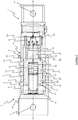
- Figure 1
- is a side cross-sectional view of a connector received in a complementary connector, with the locking member in a fully locked position and the connector locked to the complementary connector;
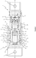
- Figure 2
- is a side cross-sectional view of the connector and complementary connector of
Figure 1 , with the locking member in a partially unlocked position and the connector locked to the complementary connector; - Figure 3
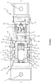
- is a side cross-sectional view of the connector and complementary connector of
Figure 1 , with the locking member in a partially unlocked position; - Figure 4
- is a side cross-sectional view of the connector and complementary connector of
Figure 1 , with the locking member in a partially unlocked position and spaced from the piston; - Figure 5
- is a side cross-sectional view of the connector and complementary connector of
Figure 1 , with the locking member in fully unlocked position and spaced from the piston and the connector unlocked and partially withdrawn from the complementary connector; and - Figure 6
- is a side cross-sectional view of the connector and complementary connector of
Figure 1 , with the locking member in a fully unlocked position and the connector unlocked and partially withdrawn from the complementary connector. - Referring to
Figures 1 to 6 , there is shown a connector assembly comprising amale connector 1 engaged with a complementaryfemale connector 2. - The
complementary connector 2 comprises a substantiallycylindrical body 27 having anopening 28 that defines anaxially extending bore 20. Anend portion 9 of thebody 27 is angled so as to act as a guide to steer a frustoconicalfront end 22 of theconnector 1 into thebore 20 so that theconnector 1 can engage with and lock to thecomplementary connector 2. In this position, thefront end 22 of theconnector 1 abuts with the base of thebore 20 to prevent over-insertion. - The
connector 1 comprises a substantiallycylindrical body 10 having a frustoconicalfront end 22 and defining an axially extendinginternal bore 6. Thefront end 22 has a chamferedrim 30 to assist in insertion of theconnector 1 into thecomplementary connector 2. - The
bore 6 of theconnector 1 and thebore 20 of thecomplementary connector 2 each (and together) have a defined longitudinal axis X due to their substantially cylindrical shape. - The
bore 6 houses a substantiallycylindrical locking member 8 that has anend face 21 and contains aninternal bore 19. The lockingmember 8 sits concentrically within thebore 6 of thebody 10 so that the outer surface of its wall is adj acent the inner surface of the wall of thebody 10. The lockingmember 8 is axially slidable within thebore 6, towards and away from thefront end 22 of thebody 10. Thebore 6 of the lockingmember 8 houses a biasing means, in this case ahelical spring 18, which biases the lockingmember 8 away from thefront end 22 of thebody 10, towards its fully locked position. - Extending through the wall of the
body 10 of theconnector 1 is a plurality of circumferentially substantially equidistantly spacedapertures 5. Eachaperture 5 is a substantially cylindrical bore that is obliquely angled towards thefront edge 22 of thebody 10, from its radially inward region to its radially outward region at an angle of between 60 and 70 degrees to the longitudinal axis of the connector. - A locking element, in this case a
spherical locking ball 4, sits within each of theapertures 5 in thebody 10. Eachaperture 5 is sized and shaped so as to capture alocking ball 4 in such a way that a portion of the lockingball 4 can extend radially outward and inward from theaperture 5, but cannot fully escape radially outwardly from theaperture 5. This is achieved by a slight reduction in the diameter of theaperture 5 at its radially outer region. Thus, theapertures 5 allow thebody 10 to act as a ball cage to restrict movement of the lockingballs 4. - The locking
member 8 comprises a series of circumferentially equidistantly spacedpockets 17 in the outside surface of its wall. Eachpocket 17 is part hemispherical or part semi-hemispherical so as to partially receive alocking ball 4, thus the diameter of each of thepockets 17 is greater than the diameter of itscorresponding locking ball 4. Eachpocket 17 is formed with acurved ramp portion 32 that leads to a flattenedbase portion 29. Eachpocket 17 also has afront edge 31 adjacent the front (free) end of the connector. - In the embodiment shown in
Figures 1 to 6 , three equidistantly circumferentially spaced rows of lockingballs 4 are provided. The rows are each equidistantly axially spaced. Each lockingball 4 sits within arespective aperture 5 and the lockingmember 8 comprises anindividual pocket 17 in respect of each lockingball 4. - When the locking
member 8 is in its fully locked position, the lockingballs 4 are held radially outward by the lockingmember 8, by contact with the outer cylindrical surface of the locking member between thepockets 17, so that each lockingball 4 protrudes radially out of its aperture 5 (as shown inFigure 1 ). When the lockingmember 8 is in its fully unlocked position, the lockingballs 4 may be partially received into theirrespective pocket 17 so that each lockingball 4 does not protrude radially out of its aperture 5 (as shown inFigures 2 and3 ). - The pocket ramp and
edge portions apertures 5 such that when the lockingmember 8 is in a partially unlocked position, a lockingball 4 being forced into itspocket 17 urges the lockingmember 8 towards its fully unlocked position. - The
connector 1 further comprises ahydraulic actuator 23 for pushing the lockingmember 8 towards thefront end 22 of thebody 10, against the biasing force provided by thespring 18. - The
hydraulic actuator 23 comprises anaccumulator 11 held within theconnector 1 by abracket 24. Theaccumulator 11 is fluidly connected to acylinder 15 andpiston 16 arrangement. Thecylinder 15 is fixed in position so that thepiston 16 may move axially relative to thecylinder 15. In the locked position, thepiston 16 abuts the lockingmember 8 such that axial movement of thepiston 16 effects axial movement of the lockingmember 8 relative to theconnector 1. Thepiston 16 is stepped so as to form aprotrusion 25 that retains thepiston 16 within thecylinder 15 by abutting against a similar steppedprotrusion 26 on thecylinder 15. Theaccumulator 11 and thecylinder 15 are each fluidly connected to a reservoir. Theaccumulator 11 is also fluidly connected to an inlet connection to allow for supply of hydraulic fluid and the reservoir is fluidly connected to an outlet connection to allow for discharge of hydraulic fluid. - The
complementary connector 2 further comprises a series of circumferentially equidistantly spacedgrooves 7 in the inside surface of its wall. Eachgroove 7 is substantially part hemispherical so as to partially receive the protruding edge of alocking ball 4. Thus, the diameter of each of thegrooves 7 is greater than the diameter of itscorresponding locking ball 4. Eachgroove 7 is formed with aramp portion 12 that acts to guide alocking ball 4 out of thegroove 7, as a result of separation of the connector and complimentary connector, when the lockingball 4 is permitted to recede back into itsaperture 5 by the lockingmember 8 extending to its fully unlocked position. - The
ramp portions 12 are each formed at an effective angle with respect to theapertures 5 such that when an axial load is applied to separate the lockedconnector 1 from thecomplementary connector 2, friction between the surfaces of thegroove 7 and theaperture 5 that alocking ball 4 is in contact with reduces but does not eliminate the radial inward load applied to thelocking ball 4. In embodiments the ramp portions lie at an angle to the longitudinal axis of the complimentary connector (which is substantially parallel to that of the connector when the two are engaged) in therange 30 to 40 degrees. - The
connector 1 and thecomplementary connector 2 each comprise a connection means 3, 13 for connection to a cable, line, or the like. - In use, a mooring line attached to a drilling rig or other vessel (for example, not shown) is connected to the connection means 3 on the
complementary connector 2 and a mooring line attached to the seabed or another structure such as a buoy or turret (for example, not shown) is connected to the connection means 13 on theconnector 1. Accordingly, theconnector 1 and thecomplementary connector 2 when engaged with one another act as a mooring connector that connects the two mooring lines together, which secures the drilling rig to the seabed. - To connect the mooring lines to one another, the
connector 1 is inserted into theopening 28 of thecomplementary connector 2. This unlocked but inserted position is shown inFigure 6 . Theconnector 1 is then pushed into thecomplementary connector 2 until thefront edge 22 of theconnector 1 abuts with the base of theopening 28 of thecomplementary connector 2 to prevent over-insertion. Thehydraulic actuator 23 is activated to empty thecylinder 15 of hydraulic fluid so as to allow thepiston 16 to retract into thecylinder 15 and to free the lockingmember 8 to move axially towards thehydraulic actuator 23. Thespring 18 thus pushes the lockingmember 8 axially towards thehydraulic actuator 23, away from thecomplementary connector 2. This position of the lockingmember 8 is shown inFigure 2 . As the lockingmember 8 is pushed further away from thecomplementary connector 2 theramp portions 32 of thepockets 17 push thelocking balls 4 radially outwards through theapertures 5 and into engagement with thegrooves 7. Since the lockingballs 4 have been partially displaced out of thebore 6, the lockingmember 8 can retract into its fully locked position where the lockingballs 4 are positively urged radially outwards by the lockingmember 8. This action locks thecomplementary connector 2 to theconnector 1. The fully locked position of the lockingmember 8 is shown inFigure 1 , where the lockingmember 8 is retained in the fully locked position by the biasing force provided by thespring 18. - In normal use, the
connector 1 remains locked to thecomplementary connector 2, securing the drilling rig to the seabed. However, during inclement weather, for example a storm, the mooring lines attached to the connection means 3, 13 may be placed under significant tension, which applies a load to theconnector 1 and thecomplementary connector 2 that urges them to be pulled apart, out of their engagement with one another. Although the slopes and relative alignment of thegrooves 7 in thecomplementary connector 2 andapertures 5 in theconnector 1 are such that a component of radial force is applied to the lockingballs 4, as the lockingballs 4 are supported on the cylindrical outer surface of the lockingmember 8 they do not impart any axial force to the lockingmember 8. - In particular, this load is supported by the locking
balls 4 that are locking theconnector 1 to thecomplementary connector 2. When the load reaches an upper threshold, theconnector 1 andcomplementary connector 2 are unlocked from one another by a user (as will be described) in order to avoid irreparable damage. Alternatively, theconnector 1 and thecomplementary connector 2 may be disengaged from one another in order to move the drilling rig to a safe area if the inclement weather is predicted to get worse. - To unlock the
connector 1 from thecomplementary connector 2 whilst under a load, theaccumulator 11 of thehydraulic actuator 23 is activated, which draws hydraulic fluid from the input connection or reservoir and drives it into thecylinder 15. The hydraulic fluid forces thepiston 16 to move axially relative to thecylinder 15, towards thefront end 22 of theconnector 1. Consequently, this movement pushes the lockingmember 8 to slide axially within thebore 6, relative toconnector 1, against the biasing force provided by thespring 18 and towards thefront end 22. Movement of the lockingmember 8 in this way is not affected by the load urging theconnector 1 andcomplementary connector 2 apart. - As the locking
member 8 moves towards thefront end 22 of theconnector 1, thefront edge 31 of eachpocket 17 begins to pass over itsrespective aperture 5 and lockingball 4. At the same time, as theconnector 1 and thecomplementary connector 2 are being pulled apart by the tension in their respective mooring lines, the lockingballs 4 securing theconnector 1 and thecomplementary connector 2 together are under load and being pushed out of thegrooves 7 and towards the locking member 8 (and towards the longitudinal axis of the connector 1), but are retained in theirapertures 5 by their contact with thefront edges 31 of thepockets 17. - As the
hydraulic actuator 23 drives the locking member towards thefront end 22 of theconnector 1, the lockingmember 8 moves into a partially unlocked position where eachpocket 17 is only partially open and the lockingballs 4 are still retained in theirgrooves 7. When thefront edge 31 of eachpocket 17 is driven just beyond a centre point of each lockingball 4, a component of the load applied to the lockingballs 4 pushes them into the theircorresponding pockets 17 in the lockingmember 8. In particular, the oblique angle of eachaperture 5 assists in causing each lockingball 4 to roll on itsgroove ramp portion 12, out of itsgroove 7 and through itsaperture 5. Each lockingball 4 is then forced into itscorresponding pocket 17, where it initially contacts the front edge of the pocket before contacting thepocket ramp portion 32 and eventually coming to a rest on the flattenedbase portion 29 of thepocket 17. The relative alignment of theramp portion 12 of the grooves and side of theapertures 5, and to a lesser extent thefront edge 31 of thepockets 7, when the locking member is in a range of partially unlocked positions is such that load urging the connector and complimentary connector apart causes the lockingballs 4 to apply an axial force on the locking member urging it towards the unlocked positon. This continues as the lockingballs 4 are forced in to theirpockets 17 and contact thepocket ramp portions 32 and results in the lockingmember 8 being rapidly urged towards thefront end 22 of theconnector 1. This movement causes the lockingmember 8 to break free from thepiston 16 and slide into its fully unlocked position near thefront end 22 of theconnector 1, ahead of thepiston 16, as is shown inFigure 4 . The precise alignment required will vary depending on the geometry of a particular connector assembly and is within the capability of the person of ordinary skill to determine. - When the locking
member 8 is in its fully unlocked position, the lockingballs 4 are retained in theirpocket 17 and no longer protrude beyond the edge of theiraperture 5. Thus, when the lockingmember 8 is in its fully unlocked position, the lockingmember 8 prevents the lockingballs 4 from engaging with the complementary connector 2 (although it is possible that the lockingballs 4 may still contact the complementary connector 2). The fully unlocked position of the lockingmember 8 is shown inFigures 5 and6 . - As this point, since the locking
balls 4 are no longer engaged with thecomplementary connector 2, theconnector 1 may be unlocked and removed from thecomplementary connector 2 by moving it axially away from thecomplementary connector 2, as is shown inFigures 5 and6 . -
Figure 5 shows that when theconnector 1 unlocked from thecomplementary connector 2 the lockingmember 8 is still ahead of, and free from, thepiston 16. InFigure 6 the piston has caught up to the lockingmember 8 and abuts against it. - Indeed, in the described embodiment, as there is a load pulling the
connector 1 andcomplementary connector 2 apart, as soon as the load acting on the lockingballs 4 urges the lockingmember 8 into its fully unlocked position, theconnector 1 is removed from thecomplementary connector 2, which disconnects the attached mooring lines from one another and thus releases the drilling rig from the seabed. This allows the drilling rig to be moved away from the inclement weather and avoids irreparable damage to theconnector 1 and thecomplementary connector 2 during disconnection. - In contrast to connectors of the prior art where a load pulling a connector and its complementary connector locked thereto apart may cause damage when the connector and complementary connector are unlocked, the configuration of the described embodiment allows the
connector 1 and thecomplementary connector 3 to be readily unlocked under a high load without causing any damage. Indeed, as described above, the load pulling theconnector 1 and thecomplementary connector 2 apart assists their disengagement by urging the partially unlocked lockingmember 8 to its fully unlocked position. - The above embodiment is described by way of example only. Many variations are possible without departing from the scope of the invention as defined in the appended claims.
- For example, in an alternative embodiment, the mooring line attached to the drilling rig is connected to the connection means 13 on the
connector 1 and the mooring line attached to the seabed is connected to the connection means 3 on thecomplementary connector 2.
Claims (15)
- A connector (1) for use in mooring or lifting, the connector (1) being adapted for release under load from a complementary connector (2), the connector (1) comprising:at least one locking element (4) for engagement with the complementary connector (2) to lock the complementary connector (2) to the connector (1);a locking member (8) moveable from a fully locked position to a fully unlocked position, the locking member (8) being operative to permit the or each locking element (4) to lock the complementary connector (2) to the connector (1) when in the fully locked position and being operative to allow the or each locking element (4) to release the complementary connector (2) from the connector (1) when in the fully unlocked position;movement means (23) operable to move the locking member (8) from its fully locked position to its partially locked position and/or its fully unlocked position, wherein the locking member (8) and locking element (4) are arranged such that when the connector (1) is locked to the complementary connector (2) and the locking member (8) is in a partially unlocked position, a load applied to the or each locking element (4) caused by a load urging the connector (1) and the complementary connector (2) apart causes the or each locking element (4) to urge the locking member (8) towards its fully unlocked position, thereby unlocking the complementary connector (2) from the connector (1),wherein the connector (1) further comprises a body (10), and on moving from the locked position to the unlocked position the locking member (8) moves towards a free end (22) of the connector body (10).
- A connector (1) according to claim 1, wherein one or more apertures (5) are formed in the connector body (10), optionally wherein each aperture (5) is a substantially cylindrical bore.
- A connector (1) according to claim 2, wherein the connector body (10) is elongate, defining a longitudinal axis between its ends and has a front end (22) for steering towards a complimentary connector (2) and each aperture (5) is obliquely angled towards the front end (22) of the body (10), from its radially inward region to its radially outward region, optionally wherein the angle between the axis of the or each aperture (5) and the longitudinal axis of the connector body (10) is in the range 60 to 70 degrees.
- A connector (1) according to claim 2 or 3, wherein each aperture (5) is for receiving a locking element (4), optionally wherein each aperture (5) comprises a portion having a slight reduction in diameter of the aperture (5) at a radially outer region, thereby to prevent a locking element (4) passing radially out through the aperture (5).
- A connector (1) according to any one of claims 2 to 4, wherein the apertures (5) are circumferentially substantially equidistantly spaced apart, optionally wherein the apertures (5) are arranged in one or more rows spaced circumferentially around the connector (1).
- A connector (1) according to claim 5, wherein the or each row of apertures (5) is circumferentially in line with the next row, or wherein each row of apertures (5) is circumferentially offset from the next row.
- A connector (1) according to any preceding claim, further comprising a biasing means (18) for biasing the locking member (8) towards its fully locked position, optionally wherein the biasing means (18) is resilient.
- A connector (1) according to any preceding claim, further comprising one or more pockets (17) formed in the locking member (8), optionally wherein each pocket (17) is sized and/or shaped for partially housing or receiving a locking element (4), optionally wherein each pocket (17) is partially hemispherical, optionally wherein each pocket (17) comprises a front edge (31) and a pocket ramp portion (32), optionally wherein the front edge (31) and/or pocket ramp portion (32) of each pocket (17) is formed at an angle so a locking element (4) received into the pocket (17) urges the locking member (8) from its partially unlocked position towards its fully unlocked position, optionally wherein each pocket (17) is circumferentially equidistantly spaced apart, optionally wherein the pockets (17) are arranged in at least one or multiple rows spaced circumferentially around the locking member (8).
- A connector (1) according to claim 8, wherein each row of pockets (17) is circumferentially in line with the next row, optionally wherein each row of pockets (17) is circumferentially offset from the next row.
- A connector (1) according to any preceding claim, wherein the movement means (23) is operable to move the locking member (8) axially relative to the longitudinal axis of the connector (1).
- A connector (1) according to claim 10, wherein the movement means (23) comprises a hydraulic actuator (23).
- A connector (1) according to claim 11, wherein the hydraulic actuator (23) comprises an accumulator (11) that is fluidly connected to a cylinder (15) and piston (16) arrangement, optionally wherein the movement means (23) is configured to be remotely operated and controlled.
- A connector (1) according to any preceding claim, further comprising a plurality of locking elements (4), optionally wherein the locking element (4) or locking elements (4) are spherical or rolling elements, optionally wherein the locking element (4) or locking elements (4) are locking balls (4).
- A connector (1) according to any preceding claim, further comprising a connection means (3) for connection to a cable, line, or the like.
- A connector assembly comprising a connector (1) according to any preceding claim; and
a complementary connector (2), optionally further comprising one or more grooves (7) formed in an inner surface of the complementary connector (2), optionally wherein each groove (7) is associated with one or more apertures (5) in the connector (1), optionally wherein each groove (7) is sized and/or shaped for partially housing or receiving at least one locking element (4), optionally wherein each groove (7) is substantially partially hemispherical, optionally wherein the diameter of each groove (7) is greater than the diameter of its corresponding locking element (4), optionally wherein each groove (7) comprises a ramp portion (12) formed at an angle for guiding a locking element (4) in and out of the groove, optionally wherein the ramp portion (12) of each groove (7) is arranged so that a load urging a locked connector (1) and complimentary connector (2) apart causes a radial force to be applied to a locking element (4) received in the groove (7), urging it towards the connector (1), optionally wherein the complimentary connector (2) has a longitudinal axis and the ramp portion (12) extends at an angle to the longitudinal axis in the range 30 to 40 degrees, optionally wherein the complementary connector (2) further comprises a connection means (13) for connection to a cable, line, or the like.
Applications Claiming Priority (2)
| Application Number | Priority Date | Filing Date | Title |
|---|---|---|---|
| GB1611126.2A GB2551716B (en) | 2016-06-27 | 2016-06-27 | A connector with locking elements releasable under load |
| PCT/GB2017/051874 WO2018002605A1 (en) | 2016-06-27 | 2017-06-27 | A mooring connector |
Publications (2)
| Publication Number | Publication Date |
|---|---|
| EP3475157A1 EP3475157A1 (en) | 2019-05-01 |
| EP3475157B1 true EP3475157B1 (en) | 2020-10-21 |
Family
ID=56891483
Family Applications (1)
| Application Number | Title | Priority Date | Filing Date |
|---|---|---|---|
| EP17748851.7A Active EP3475157B1 (en) | 2016-06-27 | 2017-06-27 | A mooring connector |
Country Status (6)
| Country | Link |
|---|---|
| US (1) | US10883571B2 (en) |
| EP (1) | EP3475157B1 (en) |
| AU (1) | AU2017291444B2 (en) |
| CA (1) | CA3027304C (en) |
| GB (1) | GB2551716B (en) |
| WO (1) | WO2018002605A1 (en) |
Cited By (1)
| Publication number | Priority date | Publication date | Assignee | Title |
|---|---|---|---|---|
| FR3131769A1 (en) * | 2022-01-12 | 2023-07-14 | Nov-Blm | Mechanical connection device, designed for the removable mechanical connection of the free ends of two offshore lines |
Families Citing this family (14)
| Publication number | Priority date | Publication date | Assignee | Title |
|---|---|---|---|---|
| GB2553820B (en) * | 2016-09-15 | 2020-07-15 | Balltec Ltd | A lifting assembly and method |
| CN110588893B (en) * | 2019-09-25 | 2020-12-01 | 中国船舶重工集团公司第七一九研究所 | Soft rigid arm single-point mooring connecting device and ship |
| GB2588395B (en) * | 2019-10-21 | 2023-06-21 | First Subsea Ltd | Mounting device for an elongate member |
| US11655808B2 (en) * | 2020-05-22 | 2023-05-23 | Scott Wu | Variable-pressure air pump |
| US11480167B2 (en) * | 2020-05-22 | 2022-10-25 | Scott Wu | Variable pressure air pump having a first cylinder defining a first chamber and a second cylinder defining a second chamber and a discharge device including a switch with at least one flow guide portion fluidly connected to the outside |
| CA3201578A1 (en) * | 2020-12-09 | 2022-06-16 | Richard Taylor | Improved mooring connector |
| US11486377B1 (en) * | 2021-07-09 | 2022-11-01 | Scott Wu | Quickly assembled air pump comprising a cylinder with a retaining hold adjacent to an opening for a position rod wherein a retaining portion of an upper cover is engaged with the retaining hole and a conical lateral face of a piston is selectively abutted against an extension portion of the upper cover |
| CN113550716B (en) * | 2021-07-14 | 2022-06-17 | 哈尔滨工程大学 | A guide column suitable for installation of underwater equipment |
| CN118201846A (en) * | 2021-10-14 | 2024-06-14 | 索菲克股份有限公司 | Connector assembly |
| US12215759B2 (en) | 2021-10-27 | 2025-02-04 | DEIS Products LLC | Shackle with positive locking pin mechanism |
| US12228161B2 (en) * | 2022-05-03 | 2025-02-18 | Ample, Inc. | Self-aligning mechanical fastener |
| US20230382498A1 (en) * | 2022-05-27 | 2023-11-30 | Compx International Inc. | Quick release pin marine mount system for rod holders and accessories |
| CN114701601B (en) * | 2022-06-01 | 2022-08-23 | 中海油能源发展股份有限公司采油服务分公司 | Mooring underwater installation locking type quick connecting device |
| IT202300004395A1 (en) * | 2023-05-11 | 2024-11-11 | I Carbon Srl | RETRACTABLE TYPE BOLTS |
Family Cites Families (16)
| Publication number | Priority date | Publication date | Assignee | Title |
|---|---|---|---|---|
| DE1273157B (en) * | 1965-07-20 | 1968-07-18 | August Laepple G M B H & Co | Carrying device for hanging and handling heavy loads |
| US3430305A (en) * | 1967-05-19 | 1969-03-04 | Ted Geffner | Releasable connectors |
| US3680906A (en) | 1970-10-12 | 1972-08-01 | Programmed & Remote Syst Corp | Removable eye bolt for lifting heavy objects |
| US3905190A (en) * | 1974-10-30 | 1975-09-16 | Michael D Pearlman | Release mechanism for large chain |
| US4573725A (en) | 1984-04-02 | 1986-03-04 | Griffiths Edward E | Remote controlled crane hook coupler |
| FR2599105B1 (en) * | 1986-05-23 | 1988-08-19 | Elf Aquitaine | CONNECTION DEVICE FOR A GUIDE LINE OF AN UNDERWATER INSTALLATION |
| US4863205A (en) | 1987-09-04 | 1989-09-05 | Jergens, Incorporated | Load ring assembly |
| NO313003B1 (en) | 2000-05-19 | 2002-07-29 | Knut Ove Steinhovden | Buoy-triggerable mechanical coupling |
| US7104505B2 (en) * | 2001-11-01 | 2006-09-12 | Michigan Aerospace Corporation | Autonomous satellite docking system |
| GB0506406D0 (en) * | 2005-03-30 | 2005-05-04 | Crp Group Ltd | Connector |
| GB2424932A (en) * | 2005-04-06 | 2006-10-11 | Bsw Ltd | Gripping device with helically or randomly arranged members to avoid excessive grooving |
| GB0507518D0 (en) | 2005-04-14 | 2005-05-18 | Balltec Ltd | A connector |
| US20140110129A1 (en) * | 2012-10-19 | 2014-04-24 | Smith International, Inc. | Hydraulic disconnect |
| GB201303199D0 (en) * | 2013-02-22 | 2013-04-10 | Ecolok Ltd | Marine connector |
| US9683416B2 (en) * | 2013-05-31 | 2017-06-20 | Halliburton Energy Services, Inc. | System and methods for recovering hydrocarbons |
| US9771762B2 (en) * | 2014-02-07 | 2017-09-26 | Klx Energy Services Llc | Downhole separation apparatus and method |
-
2016
- 2016-06-27 GB GB1611126.2A patent/GB2551716B/en active Active
-
2017
- 2017-06-27 CA CA3027304A patent/CA3027304C/en active Active
- 2017-06-27 WO PCT/GB2017/051874 patent/WO2018002605A1/en not_active Ceased
- 2017-06-27 US US16/309,869 patent/US10883571B2/en active Active
- 2017-06-27 EP EP17748851.7A patent/EP3475157B1/en active Active
- 2017-06-27 AU AU2017291444A patent/AU2017291444B2/en active Active
Non-Patent Citations (1)
| Title |
|---|
| None * |
Cited By (2)
| Publication number | Priority date | Publication date | Assignee | Title |
|---|---|---|---|---|
| FR3131769A1 (en) * | 2022-01-12 | 2023-07-14 | Nov-Blm | Mechanical connection device, designed for the removable mechanical connection of the free ends of two offshore lines |
| EP4212424A1 (en) * | 2022-01-12 | 2023-07-19 | Nov - Blm | Mechanical connection device designed for the detachable mechanical connection of the free ends of two offshore lines |
Also Published As
| Publication number | Publication date |
|---|---|
| WO2018002605A1 (en) | 2018-01-04 |
| GB2551716A (en) | 2018-01-03 |
| GB201611126D0 (en) | 2016-08-10 |
| US10883571B2 (en) | 2021-01-05 |
| CA3027304C (en) | 2022-06-21 |
| GB2551716B (en) | 2019-02-06 |
| CA3027304A1 (en) | 2018-01-04 |
| AU2017291444A1 (en) | 2019-01-03 |
| EP3475157A1 (en) | 2019-05-01 |
| US20190309824A1 (en) | 2019-10-10 |
| AU2017291444B2 (en) | 2020-04-09 |
Similar Documents
| Publication | Publication Date | Title |
|---|---|---|
| CA3027304C (en) | A mooring connector | |
| EP3400638B1 (en) | Foundation interface device | |
| EP2329100B1 (en) | A riser connector | |
| EP4001672B1 (en) | Connector | |
| EP2932013B1 (en) | Subsea connector assembly | |
| EP2100000B1 (en) | A connector | |
| EP2001734B1 (en) | Connector assemblies for connecting members under tension | |
| AU2006201299B2 (en) | Connector | |
| EP2800685B1 (en) | Preloaded mooring connector | |
| JP2018512033A (en) | Attachment device for long flexible members | |
| US20160052752A1 (en) | Marine connector | |
| NO20161518A1 (en) | Slip release assembly with cone undermining feature | |
| US10287859B2 (en) | Apparatus and method for disconnecting male and female connectors | |
| US10767441B2 (en) | Storm plug packer system and method |
Legal Events
| Date | Code | Title | Description |
|---|---|---|---|
| STAA | Information on the status of an ep patent application or granted ep patent |
Free format text: STATUS: UNKNOWN |
|
| STAA | Information on the status of an ep patent application or granted ep patent |
Free format text: STATUS: THE INTERNATIONAL PUBLICATION HAS BEEN MADE |
|
| PUAI | Public reference made under article 153(3) epc to a published international application that has entered the european phase |
Free format text: ORIGINAL CODE: 0009012 |
|
| STAA | Information on the status of an ep patent application or granted ep patent |
Free format text: STATUS: REQUEST FOR EXAMINATION WAS MADE |
|
| 17P | Request for examination filed |
Effective date: 20190125 |
|
| AK | Designated contracting states |
Kind code of ref document: A1 Designated state(s): AL AT BE BG CH CY CZ DE DK EE ES FI FR GB GR HR HU IE IS IT LI LT LU LV MC MK MT NL NO PL PT RO RS SE SI SK SM TR |
|
| AX | Request for extension of the european patent |
Extension state: BA ME |
|
| DAV | Request for validation of the european patent (deleted) | ||
| DAX | Request for extension of the european patent (deleted) | ||
| GRAP | Despatch of communication of intention to grant a patent |
Free format text: ORIGINAL CODE: EPIDOSNIGR1 |
|
| STAA | Information on the status of an ep patent application or granted ep patent |
Free format text: STATUS: GRANT OF PATENT IS INTENDED |
|
| INTG | Intention to grant announced |
Effective date: 20200507 |
|
| GRAS | Grant fee paid |
Free format text: ORIGINAL CODE: EPIDOSNIGR3 |
|
| GRAA | (expected) grant |
Free format text: ORIGINAL CODE: 0009210 |
|
| STAA | Information on the status of an ep patent application or granted ep patent |
Free format text: STATUS: THE PATENT HAS BEEN GRANTED |
|
| AK | Designated contracting states |
Kind code of ref document: B1 Designated state(s): AL AT BE BG CH CY CZ DE DK EE ES FI FR GB GR HR HU IE IS IT LI LT LU LV MC MK MT NL NO PL PT RO RS SE SI SK SM TR |
|
| REG | Reference to a national code |
Ref country code: GB Ref legal event code: FG4D |
|
| REG | Reference to a national code |
Ref country code: CH Ref legal event code: EP |
|
| REG | Reference to a national code |
Ref country code: IE Ref legal event code: FG4D |
|
| REG | Reference to a national code |
Ref country code: DE Ref legal event code: R096 Ref document number: 602017025902 Country of ref document: DE |
|
| REG | Reference to a national code |
Ref country code: AT Ref legal event code: REF Ref document number: 1325592 Country of ref document: AT Kind code of ref document: T Effective date: 20201115 |
|
| REG | Reference to a national code |
Ref country code: NL Ref legal event code: FP |
|
| REG | Reference to a national code |
Ref country code: NO Ref legal event code: T2 Effective date: 20201021 |
|
| REG | Reference to a national code |
Ref country code: AT Ref legal event code: MK05 Ref document number: 1325592 Country of ref document: AT Kind code of ref document: T Effective date: 20201021 |
|
| PG25 | Lapsed in a contracting state [announced via postgrant information from national office to epo] |
Ref country code: GR Free format text: LAPSE BECAUSE OF FAILURE TO SUBMIT A TRANSLATION OF THE DESCRIPTION OR TO PAY THE FEE WITHIN THE PRESCRIBED TIME-LIMIT Effective date: 20210122 Ref country code: FI Free format text: LAPSE BECAUSE OF FAILURE TO SUBMIT A TRANSLATION OF THE DESCRIPTION OR TO PAY THE FEE WITHIN THE PRESCRIBED TIME-LIMIT Effective date: 20201021 Ref country code: PT Free format text: LAPSE BECAUSE OF FAILURE TO SUBMIT A TRANSLATION OF THE DESCRIPTION OR TO PAY THE FEE WITHIN THE PRESCRIBED TIME-LIMIT Effective date: 20210222 Ref country code: RS Free format text: LAPSE BECAUSE OF FAILURE TO SUBMIT A TRANSLATION OF THE DESCRIPTION OR TO PAY THE FEE WITHIN THE PRESCRIBED TIME-LIMIT Effective date: 20201021 |
|
| REG | Reference to a national code |
Ref country code: LT Ref legal event code: MG4D |
|
| PG25 | Lapsed in a contracting state [announced via postgrant information from national office to epo] |
Ref country code: ES Free format text: LAPSE BECAUSE OF FAILURE TO SUBMIT A TRANSLATION OF THE DESCRIPTION OR TO PAY THE FEE WITHIN THE PRESCRIBED TIME-LIMIT Effective date: 20201021 Ref country code: AT Free format text: LAPSE BECAUSE OF FAILURE TO SUBMIT A TRANSLATION OF THE DESCRIPTION OR TO PAY THE FEE WITHIN THE PRESCRIBED TIME-LIMIT Effective date: 20201021 Ref country code: BG Free format text: LAPSE BECAUSE OF FAILURE TO SUBMIT A TRANSLATION OF THE DESCRIPTION OR TO PAY THE FEE WITHIN THE PRESCRIBED TIME-LIMIT Effective date: 20210121 Ref country code: LV Free format text: LAPSE BECAUSE OF FAILURE TO SUBMIT A TRANSLATION OF THE DESCRIPTION OR TO PAY THE FEE WITHIN THE PRESCRIBED TIME-LIMIT Effective date: 20201021 Ref country code: IS Free format text: LAPSE BECAUSE OF FAILURE TO SUBMIT A TRANSLATION OF THE DESCRIPTION OR TO PAY THE FEE WITHIN THE PRESCRIBED TIME-LIMIT Effective date: 20210221 Ref country code: PL Free format text: LAPSE BECAUSE OF FAILURE TO SUBMIT A TRANSLATION OF THE DESCRIPTION OR TO PAY THE FEE WITHIN THE PRESCRIBED TIME-LIMIT Effective date: 20201021 Ref country code: SE Free format text: LAPSE BECAUSE OF FAILURE TO SUBMIT A TRANSLATION OF THE DESCRIPTION OR TO PAY THE FEE WITHIN THE PRESCRIBED TIME-LIMIT Effective date: 20201021 |
|
| PG25 | Lapsed in a contracting state [announced via postgrant information from national office to epo] |
Ref country code: HR Free format text: LAPSE BECAUSE OF FAILURE TO SUBMIT A TRANSLATION OF THE DESCRIPTION OR TO PAY THE FEE WITHIN THE PRESCRIBED TIME-LIMIT Effective date: 20201021 |
|
| REG | Reference to a national code |
Ref country code: DE Ref legal event code: R097 Ref document number: 602017025902 Country of ref document: DE |
|
| PG25 | Lapsed in a contracting state [announced via postgrant information from national office to epo] |
Ref country code: SK Free format text: LAPSE BECAUSE OF FAILURE TO SUBMIT A TRANSLATION OF THE DESCRIPTION OR TO PAY THE FEE WITHIN THE PRESCRIBED TIME-LIMIT Effective date: 20201021 Ref country code: RO Free format text: LAPSE BECAUSE OF FAILURE TO SUBMIT A TRANSLATION OF THE DESCRIPTION OR TO PAY THE FEE WITHIN THE PRESCRIBED TIME-LIMIT Effective date: 20201021 Ref country code: LT Free format text: LAPSE BECAUSE OF FAILURE TO SUBMIT A TRANSLATION OF THE DESCRIPTION OR TO PAY THE FEE WITHIN THE PRESCRIBED TIME-LIMIT Effective date: 20201021 Ref country code: CZ Free format text: LAPSE BECAUSE OF FAILURE TO SUBMIT A TRANSLATION OF THE DESCRIPTION OR TO PAY THE FEE WITHIN THE PRESCRIBED TIME-LIMIT Effective date: 20201021 Ref country code: EE Free format text: LAPSE BECAUSE OF FAILURE TO SUBMIT A TRANSLATION OF THE DESCRIPTION OR TO PAY THE FEE WITHIN THE PRESCRIBED TIME-LIMIT Effective date: 20201021 Ref country code: SM Free format text: LAPSE BECAUSE OF FAILURE TO SUBMIT A TRANSLATION OF THE DESCRIPTION OR TO PAY THE FEE WITHIN THE PRESCRIBED TIME-LIMIT Effective date: 20201021 |
|
| PLBE | No opposition filed within time limit |
Free format text: ORIGINAL CODE: 0009261 |
|
| STAA | Information on the status of an ep patent application or granted ep patent |
Free format text: STATUS: NO OPPOSITION FILED WITHIN TIME LIMIT |
|
| PG25 | Lapsed in a contracting state [announced via postgrant information from national office to epo] |
Ref country code: DK Free format text: LAPSE BECAUSE OF FAILURE TO SUBMIT A TRANSLATION OF THE DESCRIPTION OR TO PAY THE FEE WITHIN THE PRESCRIBED TIME-LIMIT Effective date: 20201021 |
|
| 26N | No opposition filed |
Effective date: 20210722 |
|
| PG25 | Lapsed in a contracting state [announced via postgrant information from national office to epo] |
Ref country code: AL Free format text: LAPSE BECAUSE OF FAILURE TO SUBMIT A TRANSLATION OF THE DESCRIPTION OR TO PAY THE FEE WITHIN THE PRESCRIBED TIME-LIMIT Effective date: 20201021 Ref country code: IT Free format text: LAPSE BECAUSE OF FAILURE TO SUBMIT A TRANSLATION OF THE DESCRIPTION OR TO PAY THE FEE WITHIN THE PRESCRIBED TIME-LIMIT Effective date: 20201021 |
|
| PG25 | Lapsed in a contracting state [announced via postgrant information from national office to epo] |
Ref country code: SI Free format text: LAPSE BECAUSE OF FAILURE TO SUBMIT A TRANSLATION OF THE DESCRIPTION OR TO PAY THE FEE WITHIN THE PRESCRIBED TIME-LIMIT Effective date: 20201021 |
|
| REG | Reference to a national code |
Ref country code: DE Ref legal event code: R119 Ref document number: 602017025902 Country of ref document: DE |
|
| PG25 | Lapsed in a contracting state [announced via postgrant information from national office to epo] |
Ref country code: MC Free format text: LAPSE BECAUSE OF FAILURE TO SUBMIT A TRANSLATION OF THE DESCRIPTION OR TO PAY THE FEE WITHIN THE PRESCRIBED TIME-LIMIT Effective date: 20201021 |
|
| REG | Reference to a national code |
Ref country code: CH Ref legal event code: PL |
|
| REG | Reference to a national code |
Ref country code: BE Ref legal event code: MM Effective date: 20210630 |
|
| PG25 | Lapsed in a contracting state [announced via postgrant information from national office to epo] |
Ref country code: LU Free format text: LAPSE BECAUSE OF NON-PAYMENT OF DUE FEES Effective date: 20210627 |
|
| PG25 | Lapsed in a contracting state [announced via postgrant information from national office to epo] |
Ref country code: LI Free format text: LAPSE BECAUSE OF NON-PAYMENT OF DUE FEES Effective date: 20210630 Ref country code: IE Free format text: LAPSE BECAUSE OF NON-PAYMENT OF DUE FEES Effective date: 20210627 Ref country code: DE Free format text: LAPSE BECAUSE OF NON-PAYMENT OF DUE FEES Effective date: 20220101 Ref country code: CH Free format text: LAPSE BECAUSE OF NON-PAYMENT OF DUE FEES Effective date: 20210630 |
|
| PG25 | Lapsed in a contracting state [announced via postgrant information from national office to epo] |
Ref country code: IS Free format text: LAPSE BECAUSE OF FAILURE TO SUBMIT A TRANSLATION OF THE DESCRIPTION OR TO PAY THE FEE WITHIN THE PRESCRIBED TIME-LIMIT Effective date: 20210221 |
|
| PG25 | Lapsed in a contracting state [announced via postgrant information from national office to epo] |
Ref country code: BE Free format text: LAPSE BECAUSE OF NON-PAYMENT OF DUE FEES Effective date: 20210630 |
|
| P01 | Opt-out of the competence of the unified patent court (upc) registered |
Effective date: 20230518 |
|
| PG25 | Lapsed in a contracting state [announced via postgrant information from national office to epo] |
Ref country code: CY Free format text: LAPSE BECAUSE OF FAILURE TO SUBMIT A TRANSLATION OF THE DESCRIPTION OR TO PAY THE FEE WITHIN THE PRESCRIBED TIME-LIMIT Effective date: 20201021 |
|
| PG25 | Lapsed in a contracting state [announced via postgrant information from national office to epo] |
Ref country code: HU Free format text: LAPSE BECAUSE OF FAILURE TO SUBMIT A TRANSLATION OF THE DESCRIPTION OR TO PAY THE FEE WITHIN THE PRESCRIBED TIME-LIMIT; INVALID AB INITIO Effective date: 20170627 |
|
| PG25 | Lapsed in a contracting state [announced via postgrant information from national office to epo] |
Ref country code: MK Free format text: LAPSE BECAUSE OF FAILURE TO SUBMIT A TRANSLATION OF THE DESCRIPTION OR TO PAY THE FEE WITHIN THE PRESCRIBED TIME-LIMIT Effective date: 20201021 |
|
| PG25 | Lapsed in a contracting state [announced via postgrant information from national office to epo] |
Ref country code: TR Free format text: LAPSE BECAUSE OF FAILURE TO SUBMIT A TRANSLATION OF THE DESCRIPTION OR TO PAY THE FEE WITHIN THE PRESCRIBED TIME-LIMIT Effective date: 20201021 |
|
| PG25 | Lapsed in a contracting state [announced via postgrant information from national office to epo] |
Ref country code: MT Free format text: LAPSE BECAUSE OF FAILURE TO SUBMIT A TRANSLATION OF THE DESCRIPTION OR TO PAY THE FEE WITHIN THE PRESCRIBED TIME-LIMIT Effective date: 20201021 |
|
| PGFP | Annual fee paid to national office [announced via postgrant information from national office to epo] |
Ref country code: GB Payment date: 20250626 Year of fee payment: 9 |
|
| PGFP | Annual fee paid to national office [announced via postgrant information from national office to epo] |
Ref country code: NO Payment date: 20250627 Year of fee payment: 9 |
|
| PGFP | Annual fee paid to national office [announced via postgrant information from national office to epo] |
Ref country code: NL Payment date: 20250627 Year of fee payment: 9 |
|
| PGFP | Annual fee paid to national office [announced via postgrant information from national office to epo] |
Ref country code: FR Payment date: 20250626 Year of fee payment: 9 |