EP1710450A1 - A gripping device - Google Patents
A gripping device Download PDFInfo
- Publication number
- EP1710450A1 EP1710450A1 EP06251800A EP06251800A EP1710450A1 EP 1710450 A1 EP1710450 A1 EP 1710450A1 EP 06251800 A EP06251800 A EP 06251800A EP 06251800 A EP06251800 A EP 06251800A EP 1710450 A1 EP1710450 A1 EP 1710450A1
- Authority
- EP
- European Patent Office
- Prior art keywords
- elongate member
- gripping device
- balls
- ramped surfaces
- mandrel
- Prior art date
- Legal status (The legal status is an assumption and is not a legal conclusion. Google has not performed a legal analysis and makes no representation as to the accuracy of the status listed.)
- Granted
Links
- 238000003491 array Methods 0.000 claims abstract description 3
- 238000005096 rolling process Methods 0.000 claims description 10
- 230000000717 retained effect Effects 0.000 claims description 3
- SGPGESCZOCHFCL-UHFFFAOYSA-N Tilisolol hydrochloride Chemical compound [Cl-].C1=CC=C2C(=O)N(C)C=C(OCC(O)C[NH2+]C(C)(C)C)C2=C1 SGPGESCZOCHFCL-UHFFFAOYSA-N 0.000 claims 1
- 238000011084 recovery Methods 0.000 abstract description 5
- 230000000694 effects Effects 0.000 description 2
- 230000000712 assembly Effects 0.000 description 1
- 238000000429 assembly Methods 0.000 description 1
Images
Classifications
-
- F—MECHANICAL ENGINEERING; LIGHTING; HEATING; WEAPONS; BLASTING
- F16—ENGINEERING ELEMENTS AND UNITS; GENERAL MEASURES FOR PRODUCING AND MAINTAINING EFFECTIVE FUNCTIONING OF MACHINES OR INSTALLATIONS; THERMAL INSULATION IN GENERAL
- F16B—DEVICES FOR FASTENING OR SECURING CONSTRUCTIONAL ELEMENTS OR MACHINE PARTS TOGETHER, e.g. NAILS, BOLTS, CIRCLIPS, CLAMPS, CLIPS OR WEDGES; JOINTS OR JOINTING
- F16B7/00—Connections of rods or tubes, e.g. of non-circular section, mutually, including resilient connections
- F16B7/02—Connections of rods or tubes, e.g. of non-circular section, mutually, including resilient connections with conical parts
- F16B7/025—Connections of rods or tubes, e.g. of non-circular section, mutually, including resilient connections with conical parts with the expansion of an element inside the tubes due to axial movement towards a wedge or conical element
-
- F—MECHANICAL ENGINEERING; LIGHTING; HEATING; WEAPONS; BLASTING
- F16—ENGINEERING ELEMENTS AND UNITS; GENERAL MEASURES FOR PRODUCING AND MAINTAINING EFFECTIVE FUNCTIONING OF MACHINES OR INSTALLATIONS; THERMAL INSULATION IN GENERAL
- F16B—DEVICES FOR FASTENING OR SECURING CONSTRUCTIONAL ELEMENTS OR MACHINE PARTS TOGETHER, e.g. NAILS, BOLTS, CIRCLIPS, CLAMPS, CLIPS OR WEDGES; JOINTS OR JOINTING
- F16B2/00—Friction-grip releasable fastenings
- F16B2/02—Clamps, i.e. with gripping action effected by positive means other than the inherent resistance to deformation of the material of the fastening
- F16B2/16—Clamps, i.e. with gripping action effected by positive means other than the inherent resistance to deformation of the material of the fastening using rollers or balls
-
- B—PERFORMING OPERATIONS; TRANSPORTING
- B63—SHIPS OR OTHER WATERBORNE VESSELS; RELATED EQUIPMENT
- B63B—SHIPS OR OTHER WATERBORNE VESSELS; EQUIPMENT FOR SHIPPING
- B63B21/00—Tying-up; Shifting, towing, or pushing equipment; Anchoring
- B63B2021/003—Mooring or anchoring equipment, not otherwise provided for
Definitions
- This invention concerns a gripping device and particularly, though not exclusively, a device to serve as a pipeline recovery tool or mooring connector.
- a mooring connector being a device which is inserted into an anchored receptor, for example on the sea bed, and responds to a pull from a mooring line attached to the connector, by locking together the connector and the receptor.
- a pipeline recovery tool may be in the form of a mandrel which is placed inside a pipe and when pulled locks the tool and the pipe together.
- a tool may be of tubular form to be located around an object to be recovered, again operating such that the tool and the object become interlocked when the tool is pulled.
- the device involves so-called ball and taper assemblies, and comprises a pair of elongate members, one of which has an array of ramped surfaces while the other comprises a ball cage with an array of balls interacting with the ramped surfaces such that relative movement of the two elongate members causes the balls to protrude through apertures in the ball cage thus to engage, internally or externally, the pipe or other object to be gripped.
- a mooring connector a mooring line is thus connected to a fixed anchor, some means being provided to release the connector from the anchor when required.
- the ramped surfaces of the mandrel, the apertures of the ball cage, and the balls residing therein, are disposed in longitudinally spaced annular rows around the gripping device. Since the gripping relationship between the device and the object to be gripped involves considerable force, the effect is that the balls tend to become partially embedded within the surface of the object to be gripped with the result that after repeated use of the device, the receptive object displays regular annular grooves created by the rows of balls. It is an object of the present invention to provide a gripping device of this general kind but where such a disadvantage is at least substantially overcome.
- a gripping device comprising a first elongate member, a plurality of ramped surfaces spaced apart thereon, a second elongate member superimposed with respect to the ramped surfaces of the first elongate member, a plurality of rolling members captively retained within apertures of the second elongate member so as to reside respectively on the ramped surfaces of the first elongate member, and means permitting relative movement of first and second elongate members to cause the rolling members to ascend the ramped surfaces so as to protrude partially through their respective apertures; characterised in that the rolling members and their respective ramped surfaces and apertures are disposed randomly about the device or in longitudinally spaced rows where the rolling members of each row are offset laterally with respect to those of the next succeeding row.
- the rolling members may be disposed in helical arrays.
- the first elongate member may be a mandrel of circular cross-section having the second elongate member concentrically disposed around it.
- the first elongate member may be tubular and of circular cross-section having the second elongate member concentrically disposed within it.
- the first and second elongate members may be arranged for longitudinal movement, one with respect to the other.
- the second elongate member may be a ball cage having an array of apertures through which the respective balls may protrude.
- a mooring connector comprises a mandrel (10) having a ball cage (11) with rows (12) of balls protruding therethrough. At one end of the mandrel (10) is an eye (13) to which may be connected to a mooring line.
- a hydraulic or other ram mechanism (14) provides limited relative longitudinal movement between the mandrel (10) and the ball cage (11).
- Fig. 2 it will be seen that the balls (12) are captively retained by the cage (11) each on a ramped surface (15) of the mandrel (10) with the result that relative longitudinal movement of the mandrel and the ball cage causes the balls (12) to ascend their respective ramped surfaces (15) thus to protrude outwardly through the respective apertures in the ball cage (11).
- Such a connector is typically inserted into a cylindrical receptor (not shown) whereupon a pull on the mooring line serves to advance the balls (12) through the ball cage (11) to engage an adjacent inner surface of the receptor.
- the interlocking strength of the two parts is proportional to the force of the pull on the connector. In effect, the balls (12) become partially embedded within the adjacent wall of the receptor to assist in maintaining the interlock.
- the balls (12), their respective apertures in the ball cage, and ramped surfaces (15) in the mandrel are arranged in a helical pattern such that the balls of each circumferential row are offset laterally with respect to those of the next succeeding row.
- the balls may be arranged in a completely random fashion provided they achieve the result of avoiding excessive regularity of rows and columns as in the case of the conventional arrangement of Figs. 1 to 3.
Landscapes
- Engineering & Computer Science (AREA)
- General Engineering & Computer Science (AREA)
- Mechanical Engineering (AREA)
- Earth Drilling (AREA)
- Manipulator (AREA)
- Advancing Webs (AREA)
- Gripping Jigs, Holding Jigs, And Positioning Jigs (AREA)
- Wire Bonding (AREA)
- Clamps And Clips (AREA)
- Shaping Of Tube Ends By Bending Or Straightening (AREA)
Abstract
Description
- This invention concerns a gripping device and particularly, though not exclusively, a device to serve as a pipeline recovery tool or mooring connector.
- Devices of this kind are known and described, for example, in patent specification
WO 2004/055394 which refers to a mooring connector being a device which is inserted into an anchored receptor, for example on the sea bed, and responds to a pull from a mooring line attached to the connector, by locking together the connector and the receptor. - Alternatively, a pipeline recovery tool may be in the form of a mandrel which is placed inside a pipe and when pulled locks the tool and the pipe together. In some cases, such a tool may be of tubular form to be located around an object to be recovered, again operating such that the tool and the object become interlocked when the tool is pulled.
- The device involves so-called ball and taper assemblies, and comprises a pair of elongate members, one of which has an array of ramped surfaces while the other comprises a ball cage with an array of balls interacting with the ramped surfaces such that relative movement of the two elongate members causes the balls to protrude through apertures in the ball cage thus to engage, internally or externally, the pipe or other object to be gripped. In the case of a mooring connector a mooring line is thus connected to a fixed anchor, some means being provided to release the connector from the anchor when required.
- In all such devices the ramped surfaces of the mandrel, the apertures of the ball cage, and the balls residing therein, are disposed in longitudinally spaced annular rows around the gripping device. Since the gripping relationship between the device and the object to be gripped involves considerable force, the effect is that the balls tend to become partially embedded within the surface of the object to be gripped with the result that after repeated use of the device, the receptive object displays regular annular grooves created by the rows of balls. It is an object of the present invention to provide a gripping device of this general kind but where such a disadvantage is at least substantially overcome.
- According to the present invention there is provided a gripping device comprising a first elongate member, a plurality of ramped surfaces spaced apart thereon, a second elongate member superimposed with respect to the ramped surfaces of the first elongate member, a plurality of rolling members captively retained within apertures of the second elongate member so as to reside respectively on the ramped surfaces of the first elongate member, and means permitting relative movement of first and second elongate members to cause the rolling members to ascend the ramped surfaces so as to protrude partially through their respective apertures; characterised in that the rolling members and their respective ramped surfaces and apertures are disposed randomly about the device or in longitudinally spaced rows where the rolling members of each row are offset laterally with respect to those of the next succeeding row.
- The rolling members may be disposed in helical arrays.
- The first elongate member may be a mandrel of circular cross-section having the second elongate member concentrically disposed around it.
- The first elongate member may be tubular and of circular cross-section having the second elongate member concentrically disposed within it.
- The first and second elongate members may be arranged for longitudinal movement, one with respect to the other.
- The second elongate member may be a ball cage having an array of apertures through which the respective balls may protrude.
- An embodiment of the invention will now be described, by way of example only, with reference to the accompanying drawings in which:
- Fig. 1
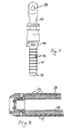
- shows a mooring connector or pipeline recovery tool of a conventional design;
- Fig. 2
- is a cross-sectional view through one end of the connector of Fig. 1;
- Fig. 3
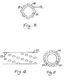
- is a schematic representation of an end view of a tool of the kind shown in Fig. 1;
- Fig. 4
- is a schematic view of a part of such a tool modified in accordance with the invention; and
- Fig. 5
- is a schematic end view of the modified tool represented in Fig. 4
- Referring now to the drawings, a mooring connector comprises a mandrel (10) having a ball cage (11) with rows (12) of balls protruding therethrough. At one end of the mandrel (10) is an eye (13) to which may be connected to a mooring line. A hydraulic or other ram mechanism (14) provides limited relative longitudinal movement between the mandrel (10) and the ball cage (11).
- Referring now to Fig. 2, it will be seen that the balls (12) are captively retained by the cage (11) each on a ramped surface (15) of the mandrel (10) with the result that relative longitudinal movement of the mandrel and the ball cage causes the balls (12) to ascend their respective ramped surfaces (15) thus to protrude outwardly through the respective apertures in the ball cage (11).
- Such a connector is typically inserted into a cylindrical receptor (not shown) whereupon a pull on the mooring line serves to advance the balls (12) through the ball cage (11) to engage an adjacent inner surface of the receptor. The interlocking strength of the two parts is proportional to the force of the pull on the connector. In effect, the balls (12) become partially embedded within the adjacent wall of the receptor to assist in maintaining the interlock.
- Referring now to Fig. 3, it will be seen that the longitudinal alignment of the balls of adjacent rows results in longitudinally directed surface areas (16) of the mandrel having no contact with the inner surface of the receptor and so any relative movement of the connector with the receptor will tend to create longitudinal columns and annular rows of grooves in the receptor wall which can lead to distortion of the receptor.
- Referring now to Fig. 4, and in accordance with the present invention, the balls (12), their respective apertures in the ball cage, and ramped surfaces (15) in the mandrel are arranged in a helical pattern such that the balls of each circumferential row are offset laterally with respect to those of the next succeeding row.
- Referring now to Fig. 5, it will be seen that this arrangement leaves no continuous longitudinal spaces between columns of balls as is the case in the conventional arrangement. The effective non-uniform arrangement of the balls therefore results in a more uniform grip upon the adjacent surface of the receptor with the result that excessive grooving or deformation of the latter is substantially avoided.
- Within the scope of the invention, the balls may be arranged in a completely random fashion provided they achieve the result of avoiding excessive regularity of rows and columns as in the case of the conventional arrangement of Figs. 1 to 3.
- It will be understood that while this invention has been described in relation to an embodiment of a mooring anchor or pipeline recovery tool. Nevertheless, it can be applied also to gripping members adapted to grip an outer surface of an object to be recovered thereby or connected thereto. In such a case, the ball cage will be located within a body having ramped surfaces.
Claims (6)
- A gripping device comprising a first elongate member, a plurality of ramped surfaces spaced apart thereon, a second elongate member superimposed with respect to the ramped surfaces of the first elongate member, a plurality of rolling members captively retained within apertures of the second elongate member so as to reside respectively on the ramped surfaces of the first elongate member and means permitting relative movement of the first and second elongate members to cause the rolling members to ascend the ramped surfaces so to protrude partially through their respective apertures; characterised in that the rolling members and their respective ramped surfaces and apertures are disposed randomly about the device or in longitudinally spaced rows where the rolling members of each row are offset Iaterafly with respect to those of the next succeeding row.
- A gripping device according to daim 1 wherein the rolling members are disposed in helical arrays.
- A gripping device according to claim 1 or claim 2 wherein the first elongate member is a mandrel of circular cross-section having the second elongate member concentrically disposed around it.
- A gripping device according to claim 1 or claim 2 wherein the first elongate member is tubular and of circular cross-section having the second elongate member concentrically disposed within it.
- A gripping device according to any preceding claim wherein the first and second elongate members are arranged for longitudinal movement, one with respect to the other.
- A gripping device substantially as hereinbefore described with reference to and as illustrated in Figs. 4 and 5 of the accompanying drawings.
Applications Claiming Priority (1)
| Application Number | Priority Date | Filing Date | Title |
|---|---|---|---|
| GB0506929A GB2424932A (en) | 2005-04-06 | 2005-04-06 | Gripping device with helically or randomly arranged members to avoid excessive grooving |
Publications (2)
| Publication Number | Publication Date |
|---|---|
| EP1710450A1 true EP1710450A1 (en) | 2006-10-11 |
| EP1710450B1 EP1710450B1 (en) | 2008-03-05 |
Family
ID=34586761
Family Applications (1)
| Application Number | Title | Priority Date | Filing Date |
|---|---|---|---|
| EP06251800A Expired - Lifetime EP1710450B1 (en) | 2005-04-06 | 2006-03-31 | A gripping device |
Country Status (6)
| Country | Link |
|---|---|
| US (1) | US7744140B2 (en) |
| EP (1) | EP1710450B1 (en) |
| AT (1) | ATE388334T1 (en) |
| DE (1) | DE602006000605T2 (en) |
| DK (1) | DK1710450T3 (en) |
| GB (1) | GB2424932A (en) |
Cited By (2)
| Publication number | Priority date | Publication date | Assignee | Title |
|---|---|---|---|---|
| GB2536075A (en) * | 2015-02-13 | 2016-09-07 | First Subsea Ltd | Mounting device for an elongate flexible member |
| WO2018002605A1 (en) * | 2016-06-27 | 2018-01-04 | Balltec Limited | A mooring connector |
Families Citing this family (15)
| Publication number | Priority date | Publication date | Assignee | Title |
|---|---|---|---|---|
| US7854266B2 (en) * | 2008-09-26 | 2010-12-21 | Halliburton Energy Services, Inc. | Smooth bore latch for tie back receptacle extension |
| WO2012100019A1 (en) * | 2011-01-21 | 2012-07-26 | 2M-Tek, Inc. | Tubular running device and method |
| US9797207B2 (en) * | 2011-01-21 | 2017-10-24 | 2M-Tek, Inc. | Actuator assembly for tubular running device |
| GB2497953A (en) * | 2011-12-22 | 2013-07-03 | Subsea Riser Products Ltd | Preloaded Mooring Connector |
| US9163651B2 (en) * | 2013-03-14 | 2015-10-20 | Meyer Ostrobrod | Concrete anchor |
| EP2992169B1 (en) * | 2013-05-02 | 2019-01-02 | Weatherford Technology Holdings, LLC | Tubular handling tool |
| GB201321416D0 (en) | 2013-12-04 | 2014-01-15 | Balltec Ltd | Apparatus and method for disconnecting male and female connectors |
| US9546524B2 (en) | 2013-12-31 | 2017-01-17 | Longyear Tm, Inc. | Handling and recovery devices for tubular members and associated methods |
| US10053973B2 (en) | 2015-09-30 | 2018-08-21 | Longyear Tm, Inc. | Braking devices for drilling operations, and systems and methods of using same |
| AU2016372033B2 (en) | 2015-12-14 | 2021-07-22 | Boart Longyear Manufacturing And Distribution Inc. | Systems and methods for releasing a portion of a drill string from a drilling cable |
| GB2549480B (en) * | 2016-04-18 | 2019-06-12 | Balltec Ltd | Pipe handling apparatus |
| GB2553820B (en) * | 2016-09-15 | 2020-07-15 | Balltec Ltd | A lifting assembly and method |
| US11131151B2 (en) * | 2017-03-02 | 2021-09-28 | Weatherford Technology Holdings, Llc | Tool coupler with sliding coupling members for top drive |
| CA3115951C (en) * | 2017-05-01 | 2022-06-28 | U-Target Energy Ltd. | Downhole telemetry sub for communication with surface |
| US10767441B2 (en) | 2018-08-31 | 2020-09-08 | Harvey Sharp, III | Storm plug packer system and method |
Citations (2)
| Publication number | Priority date | Publication date | Assignee | Title |
|---|---|---|---|---|
| EP0156575A2 (en) * | 1984-03-13 | 1985-10-02 | Owen Walmsley | Clamps |
| WO2004055394A1 (en) * | 2002-12-18 | 2004-07-01 | Bsw Limited | A connector |
Family Cites Families (12)
| Publication number | Priority date | Publication date | Assignee | Title |
|---|---|---|---|---|
| GB8406580D0 (en) * | 1984-03-13 | 1984-04-18 | Walmsley O | Pipe connector |
| GB2155577B (en) * | 1984-03-13 | 1987-11-25 | Owen Walmsley | Pipe clamps/connectors |
| GB8814699D0 (en) * | 1988-06-21 | 1988-07-27 | Cooper Ind Inc | Emergency suspension system for drill casings |
| GB2341620B (en) * | 1995-11-23 | 2000-05-03 | Red Baron | Downhole anchor |
| GB2335008A (en) | 1998-03-06 | 1999-09-08 | Phillip Fields Hayward | Fitting a gaiter without dismantling the joint |
| GB2338008B (en) * | 1998-06-05 | 2002-08-28 | Bsw Ltd | A retaining device |
| GB9815016D0 (en) * | 1998-07-13 | 1998-09-09 | Self Timothy | Method and apparatus for rewinding |
| US6513751B2 (en) * | 2000-10-19 | 2003-02-04 | Convertech, Inc. | Air differential core winding apparatus |
| DE20213388U1 (en) * | 2002-08-30 | 2004-01-15 | Cameron Gmbh | connecting device |
| GB0506406D0 (en) * | 2005-03-30 | 2005-05-04 | Crp Group Ltd | Connector |
| US7445050B2 (en) * | 2006-04-25 | 2008-11-04 | Canrig Drilling Technology Ltd. | Tubular running tool |
| US7552764B2 (en) * | 2007-01-04 | 2009-06-30 | Nabors Global Holdings, Ltd. | Tubular handling device |
-
2005
- 2005-04-06 GB GB0506929A patent/GB2424932A/en not_active Withdrawn
-
2006
- 2006-03-31 DK DK06251800T patent/DK1710450T3/en active
- 2006-03-31 AT AT06251800T patent/ATE388334T1/en not_active IP Right Cessation
- 2006-03-31 DE DE602006000605T patent/DE602006000605T2/en not_active Expired - Lifetime
- 2006-03-31 EP EP06251800A patent/EP1710450B1/en not_active Expired - Lifetime
- 2006-04-04 US US11/397,128 patent/US7744140B2/en not_active Expired - Fee Related
Patent Citations (2)
| Publication number | Priority date | Publication date | Assignee | Title |
|---|---|---|---|---|
| EP0156575A2 (en) * | 1984-03-13 | 1985-10-02 | Owen Walmsley | Clamps |
| WO2004055394A1 (en) * | 2002-12-18 | 2004-07-01 | Bsw Limited | A connector |
Cited By (5)
| Publication number | Priority date | Publication date | Assignee | Title |
|---|---|---|---|---|
| GB2536075A (en) * | 2015-02-13 | 2016-09-07 | First Subsea Ltd | Mounting device for an elongate flexible member |
| GB2536075B (en) * | 2015-02-13 | 2017-09-27 | First Subsea Ltd | Mounting device for an elongate flexible member |
| WO2018002605A1 (en) * | 2016-06-27 | 2018-01-04 | Balltec Limited | A mooring connector |
| AU2017291444B2 (en) * | 2016-06-27 | 2020-04-09 | Balltec Limited | A mooring connector |
| US10883571B2 (en) | 2016-06-27 | 2021-01-05 | Balltec Limited | Mooring connector |
Also Published As
| Publication number | Publication date |
|---|---|
| US7744140B2 (en) | 2010-06-29 |
| GB0506929D0 (en) | 2005-05-11 |
| US20060269360A1 (en) | 2006-11-30 |
| ATE388334T1 (en) | 2008-03-15 |
| EP1710450B1 (en) | 2008-03-05 |
| DK1710450T3 (en) | 2008-07-07 |
| DE602006000605D1 (en) | 2008-04-17 |
| GB2424932A (en) | 2006-10-11 |
| DE602006000605T2 (en) | 2009-04-02 |
Similar Documents
| Publication | Publication Date | Title |
|---|---|---|
| EP1710450B1 (en) | A gripping device | |
| US7607476B2 (en) | Expandable slip ring | |
| US9157482B2 (en) | Shaft assembly with anti-pull apart stake | |
| EP2511540B1 (en) | Blind rivet and fastening method thereof | |
| JP5133885B2 (en) | Zero clearance type bolt fastening joint | |
| AU2007323226A1 (en) | A connector | |
| AU2006201299B2 (en) | Connector | |
| DE2637038A1 (en) | ROLLER FREE-WHEEL CLUTCH AND ARRANGEMENT OF CAGE AND ROLLERS FOR IT | |
| EP1741945A1 (en) | Assembled camshaft | |
| CN104179812A (en) | Ball Cage Joints with Direct Pinion Mounting | |
| EP3026279B1 (en) | Method for producing a plain bearing bushing with an internal structure | |
| EP3088757B1 (en) | Claw coupling | |
| DE10084985B4 (en) | Clamping mechanism, coupling and device that incorporates both | |
| DE19647553A1 (en) | Fastening armoured flexible hose onto end of metal pipe | |
| WO2004074636A2 (en) | Radially deformed anchorage bolt | |
| JPH0818532B2 (en) | Force limiter for safety belt restraint | |
| DE1552989A1 (en) | Tube bending mandrel | |
| JP4790453B2 (en) | Foundation material for construction | |
| DE69509445T2 (en) | Clamping element for a pipe connection | |
| EP2882969B1 (en) | Expansion anchor | |
| KR102762327B1 (en) | Anchor Bolt System | |
| EP2885485B1 (en) | Slip | |
| JP6477335B2 (en) | Steel pipe pile joint rotation deterrent structure | |
| WO2016083176A1 (en) | Uncooled furnace roll and method for producing an uncooled furnace roll | |
| WO2019056025A1 (en) | Expansion assembly |
Legal Events
| Date | Code | Title | Description |
|---|---|---|---|
| PUAI | Public reference made under article 153(3) epc to a published international application that has entered the european phase |
Free format text: ORIGINAL CODE: 0009012 |
|
| AK | Designated contracting states |
Kind code of ref document: A1 Designated state(s): AT BE BG CH CY CZ DE DK EE ES FI FR GB GR HU IE IS IT LI LT LU LV MC NL PL PT RO SE SI SK TR |
|
| AX | Request for extension of the european patent |
Extension state: AL BA HR MK YU |
|
| 17P | Request for examination filed |
Effective date: 20060914 |
|
| AKX | Designation fees paid |
Designated state(s): AT BE BG CH CY CZ DE DK EE ES FI FR GB GR HU IE IS IT LI LT LU LV MC NL PL PT RO SE SI SK TR |
|
| GRAP | Despatch of communication of intention to grant a patent |
Free format text: ORIGINAL CODE: EPIDOSNIGR1 |
|
| GRAS | Grant fee paid |
Free format text: ORIGINAL CODE: EPIDOSNIGR3 |
|
| GRAA | (expected) grant |
Free format text: ORIGINAL CODE: 0009210 |
|
| AK | Designated contracting states |
Kind code of ref document: B1 Designated state(s): AT BE BG CH CY CZ DE DK EE ES FI FR GB GR HU IE IS IT LI LT LU LV MC NL PL PT RO SE SI SK TR |
|
| REG | Reference to a national code |
Ref country code: GB Ref legal event code: FG4D |
|
| REG | Reference to a national code |
Ref country code: CH Ref legal event code: EP |
|
| REG | Reference to a national code |
Ref country code: IE Ref legal event code: FG4D |
|
| REF | Corresponds to: |
Ref document number: 602006000605 Country of ref document: DE Date of ref document: 20080417 Kind code of ref document: P |
|
| REG | Reference to a national code |
Ref country code: DK Ref legal event code: T3 |
|
| PG25 | Lapsed in a contracting state [announced via postgrant information from national office to epo] |
Ref country code: ES Free format text: LAPSE BECAUSE OF FAILURE TO SUBMIT A TRANSLATION OF THE DESCRIPTION OR TO PAY THE FEE WITHIN THE PRESCRIBED TIME-LIMIT Effective date: 20080616 |
|
| PG25 | Lapsed in a contracting state [announced via postgrant information from national office to epo] |
Ref country code: AT Free format text: LAPSE BECAUSE OF FAILURE TO SUBMIT A TRANSLATION OF THE DESCRIPTION OR TO PAY THE FEE WITHIN THE PRESCRIBED TIME-LIMIT Effective date: 20080305 |
|
| NLV1 | Nl: lapsed or annulled due to failure to fulfill the requirements of art. 29p and 29m of the patents act | ||
| PG25 | Lapsed in a contracting state [announced via postgrant information from national office to epo] |
Ref country code: LV Free format text: LAPSE BECAUSE OF FAILURE TO SUBMIT A TRANSLATION OF THE DESCRIPTION OR TO PAY THE FEE WITHIN THE PRESCRIBED TIME-LIMIT Effective date: 20080305 Ref country code: SI Free format text: LAPSE BECAUSE OF FAILURE TO SUBMIT A TRANSLATION OF THE DESCRIPTION OR TO PAY THE FEE WITHIN THE PRESCRIBED TIME-LIMIT Effective date: 20080305 Ref country code: BE Free format text: LAPSE BECAUSE OF FAILURE TO SUBMIT A TRANSLATION OF THE DESCRIPTION OR TO PAY THE FEE WITHIN THE PRESCRIBED TIME-LIMIT Effective date: 20080305 Ref country code: PL Free format text: LAPSE BECAUSE OF FAILURE TO SUBMIT A TRANSLATION OF THE DESCRIPTION OR TO PAY THE FEE WITHIN THE PRESCRIBED TIME-LIMIT Effective date: 20080305 |
|
| PG25 | Lapsed in a contracting state [announced via postgrant information from national office to epo] |
Ref country code: SK Free format text: LAPSE BECAUSE OF FAILURE TO SUBMIT A TRANSLATION OF THE DESCRIPTION OR TO PAY THE FEE WITHIN THE PRESCRIBED TIME-LIMIT Effective date: 20080305 Ref country code: NL Free format text: LAPSE BECAUSE OF FAILURE TO SUBMIT A TRANSLATION OF THE DESCRIPTION OR TO PAY THE FEE WITHIN THE PRESCRIBED TIME-LIMIT Effective date: 20080305 Ref country code: PT Free format text: LAPSE BECAUSE OF FAILURE TO SUBMIT A TRANSLATION OF THE DESCRIPTION OR TO PAY THE FEE WITHIN THE PRESCRIBED TIME-LIMIT Effective date: 20080805 Ref country code: SE Free format text: LAPSE BECAUSE OF FAILURE TO SUBMIT A TRANSLATION OF THE DESCRIPTION OR TO PAY THE FEE WITHIN THE PRESCRIBED TIME-LIMIT Effective date: 20080605 Ref country code: CZ Free format text: LAPSE BECAUSE OF FAILURE TO SUBMIT A TRANSLATION OF THE DESCRIPTION OR TO PAY THE FEE WITHIN THE PRESCRIBED TIME-LIMIT Effective date: 20080305 |
|
| PG25 | Lapsed in a contracting state [announced via postgrant information from national office to epo] |
Ref country code: RO Free format text: LAPSE BECAUSE OF FAILURE TO SUBMIT A TRANSLATION OF THE DESCRIPTION OR TO PAY THE FEE WITHIN THE PRESCRIBED TIME-LIMIT Effective date: 20080305 |
|
| ET | Fr: translation filed | ||
| PG25 | Lapsed in a contracting state [announced via postgrant information from national office to epo] |
Ref country code: IS Free format text: LAPSE BECAUSE OF FAILURE TO SUBMIT A TRANSLATION OF THE DESCRIPTION OR TO PAY THE FEE WITHIN THE PRESCRIBED TIME-LIMIT Effective date: 20080705 |
|
| PLBE | No opposition filed within time limit |
Free format text: ORIGINAL CODE: 0009261 |
|
| STAA | Information on the status of an ep patent application or granted ep patent |
Free format text: STATUS: NO OPPOSITION FILED WITHIN TIME LIMIT |
|
| PG25 | Lapsed in a contracting state [announced via postgrant information from national office to epo] |
Ref country code: IE Free format text: LAPSE BECAUSE OF NON-PAYMENT OF DUE FEES Effective date: 20080331 Ref country code: LT Free format text: LAPSE BECAUSE OF FAILURE TO SUBMIT A TRANSLATION OF THE DESCRIPTION OR TO PAY THE FEE WITHIN THE PRESCRIBED TIME-LIMIT Effective date: 20080305 Ref country code: EE Free format text: LAPSE BECAUSE OF FAILURE TO SUBMIT A TRANSLATION OF THE DESCRIPTION OR TO PAY THE FEE WITHIN THE PRESCRIBED TIME-LIMIT Effective date: 20080305 |
|
| 26N | No opposition filed |
Effective date: 20081208 |
|
| PG25 | Lapsed in a contracting state [announced via postgrant information from national office to epo] |
Ref country code: BG Free format text: LAPSE BECAUSE OF FAILURE TO SUBMIT A TRANSLATION OF THE DESCRIPTION OR TO PAY THE FEE WITHIN THE PRESCRIBED TIME-LIMIT Effective date: 20080605 |
|
| PG25 | Lapsed in a contracting state [announced via postgrant information from national office to epo] |
Ref country code: CY Free format text: LAPSE BECAUSE OF FAILURE TO SUBMIT A TRANSLATION OF THE DESCRIPTION OR TO PAY THE FEE WITHIN THE PRESCRIBED TIME-LIMIT Effective date: 20080305 |
|
| PG25 | Lapsed in a contracting state [announced via postgrant information from national office to epo] |
Ref country code: LU Free format text: LAPSE BECAUSE OF NON-PAYMENT OF DUE FEES Effective date: 20080331 Ref country code: HU Free format text: LAPSE BECAUSE OF FAILURE TO SUBMIT A TRANSLATION OF THE DESCRIPTION OR TO PAY THE FEE WITHIN THE PRESCRIBED TIME-LIMIT Effective date: 20080906 |
|
| PG25 | Lapsed in a contracting state [announced via postgrant information from national office to epo] |
Ref country code: TR Free format text: LAPSE BECAUSE OF FAILURE TO SUBMIT A TRANSLATION OF THE DESCRIPTION OR TO PAY THE FEE WITHIN THE PRESCRIBED TIME-LIMIT Effective date: 20080305 |
|
| PG25 | Lapsed in a contracting state [announced via postgrant information from national office to epo] |
Ref country code: GR Free format text: LAPSE BECAUSE OF FAILURE TO SUBMIT A TRANSLATION OF THE DESCRIPTION OR TO PAY THE FEE WITHIN THE PRESCRIBED TIME-LIMIT Effective date: 20080606 |
|
| REG | Reference to a national code |
Ref country code: CH Ref legal event code: PL |
|
| PG25 | Lapsed in a contracting state [announced via postgrant information from national office to epo] |
Ref country code: CH Free format text: LAPSE BECAUSE OF NON-PAYMENT OF DUE FEES Effective date: 20100331 Ref country code: LI Free format text: LAPSE BECAUSE OF NON-PAYMENT OF DUE FEES Effective date: 20100331 |
|
| PGFP | Annual fee paid to national office [announced via postgrant information from national office to epo] |
Ref country code: FI Payment date: 20120330 Year of fee payment: 7 |
|
| PGFP | Annual fee paid to national office [announced via postgrant information from national office to epo] |
Ref country code: DE Payment date: 20120330 Year of fee payment: 7 Ref country code: MC Payment date: 20120425 Year of fee payment: 7 Ref country code: DK Payment date: 20120330 Year of fee payment: 7 |
|
| PGFP | Annual fee paid to national office [announced via postgrant information from national office to epo] |
Ref country code: FR Payment date: 20120419 Year of fee payment: 7 |
|
| PGFP | Annual fee paid to national office [announced via postgrant information from national office to epo] |
Ref country code: IT Payment date: 20120329 Year of fee payment: 7 |
|
| REG | Reference to a national code |
Ref country code: DE Ref legal event code: R082 Ref document number: 602006000605 Country of ref document: DE Representative=s name: SCHUMACHER & WILLSAU PATENTANWALTSGESELLSCHAFT, DE |
|
| REG | Reference to a national code |
Ref country code: DK Ref legal event code: EBP |
|
| PG25 | Lapsed in a contracting state [announced via postgrant information from national office to epo] |
Ref country code: FI Free format text: LAPSE BECAUSE OF NON-PAYMENT OF DUE FEES Effective date: 20130331 Ref country code: MC Free format text: LAPSE BECAUSE OF NON-PAYMENT OF DUE FEES Effective date: 20130331 |
|
| REG | Reference to a national code |
Ref country code: FR Ref legal event code: ST Effective date: 20131129 |
|
| REG | Reference to a national code |
Ref country code: DE Ref legal event code: R119 Ref document number: 602006000605 Country of ref document: DE Effective date: 20131001 |
|
| PG25 | Lapsed in a contracting state [announced via postgrant information from national office to epo] |
Ref country code: FR Free format text: LAPSE BECAUSE OF NON-PAYMENT OF DUE FEES Effective date: 20130402 Ref country code: DE Free format text: LAPSE BECAUSE OF NON-PAYMENT OF DUE FEES Effective date: 20131001 |
|
| PG25 | Lapsed in a contracting state [announced via postgrant information from national office to epo] |
Ref country code: IT Free format text: LAPSE BECAUSE OF NON-PAYMENT OF DUE FEES Effective date: 20130331 |
|
| PG25 | Lapsed in a contracting state [announced via postgrant information from national office to epo] |
Ref country code: DK Free format text: LAPSE BECAUSE OF NON-PAYMENT OF DUE FEES Effective date: 20130331 |
|
| PGFP | Annual fee paid to national office [announced via postgrant information from national office to epo] |
Ref country code: GB Payment date: 20190325 Year of fee payment: 14 |
|
| GBPC | Gb: european patent ceased through non-payment of renewal fee |
Effective date: 20200331 |
|
| PG25 | Lapsed in a contracting state [announced via postgrant information from national office to epo] |
Ref country code: GB Free format text: LAPSE BECAUSE OF NON-PAYMENT OF DUE FEES Effective date: 20200331 |