EP3475150B1 - Motorcycle comprising an auxiliary lighting device - Google Patents
Motorcycle comprising an auxiliary lighting device Download PDFInfo
- Publication number
- EP3475150B1 EP3475150B1 EP17737045.9A EP17737045A EP3475150B1 EP 3475150 B1 EP3475150 B1 EP 3475150B1 EP 17737045 A EP17737045 A EP 17737045A EP 3475150 B1 EP3475150 B1 EP 3475150B1
- Authority
- EP
- European Patent Office
- Prior art keywords
- motorcycle
- lighting device
- auxiliary lighting
- kickstand
- control unit
- Prior art date
- Legal status (The legal status is an assumption and is not a legal conclusion. Google has not performed a legal analysis and makes no representation as to the accuracy of the status listed.)
- Active
Links
Images


Classifications
-
- B—PERFORMING OPERATIONS; TRANSPORTING
- B62—LAND VEHICLES FOR TRAVELLING OTHERWISE THAN ON RAILS
- B62J—CYCLE SADDLES OR SEATS; AUXILIARY DEVICES OR ACCESSORIES SPECIALLY ADAPTED TO CYCLES AND NOT OTHERWISE PROVIDED FOR, e.g. ARTICLE CARRIERS OR CYCLE PROTECTORS
- B62J6/00—Arrangement of optical signalling or lighting devices on cycles; Mounting or supporting thereof; Circuits therefor
- B62J6/01—Electric circuits
-
- B—PERFORMING OPERATIONS; TRANSPORTING
- B62—LAND VEHICLES FOR TRAVELLING OTHERWISE THAN ON RAILS
- B62J—CYCLE SADDLES OR SEATS; AUXILIARY DEVICES OR ACCESSORIES SPECIALLY ADAPTED TO CYCLES AND NOT OTHERWISE PROVIDED FOR, e.g. ARTICLE CARRIERS OR CYCLE PROTECTORS
- B62J6/00—Arrangement of optical signalling or lighting devices on cycles; Mounting or supporting thereof; Circuits therefor
-
- B—PERFORMING OPERATIONS; TRANSPORTING
- B60—VEHICLES IN GENERAL
- B60Q—ARRANGEMENT OF SIGNALLING OR LIGHTING DEVICES, THE MOUNTING OR SUPPORTING THEREOF OR CIRCUITS THEREFOR, FOR VEHICLES IN GENERAL
- B60Q1/00—Arrangement of optical signalling or lighting devices, the mounting or supporting thereof or circuits therefor
- B60Q1/02—Arrangement of optical signalling or lighting devices, the mounting or supporting thereof or circuits therefor the devices being primarily intended to illuminate the way ahead or to illuminate other areas of way or environments
- B60Q1/04—Arrangement of optical signalling or lighting devices, the mounting or supporting thereof or circuits therefor the devices being primarily intended to illuminate the way ahead or to illuminate other areas of way or environments the devices being headlights
- B60Q1/18—Arrangement of optical signalling or lighting devices, the mounting or supporting thereof or circuits therefor the devices being primarily intended to illuminate the way ahead or to illuminate other areas of way or environments the devices being headlights being additional front lights
-
- B—PERFORMING OPERATIONS; TRANSPORTING
- B62—LAND VEHICLES FOR TRAVELLING OTHERWISE THAN ON RAILS
- B62J—CYCLE SADDLES OR SEATS; AUXILIARY DEVICES OR ACCESSORIES SPECIALLY ADAPTED TO CYCLES AND NOT OTHERWISE PROVIDED FOR, e.g. ARTICLE CARRIERS OR CYCLE PROTECTORS
- B62J6/00—Arrangement of optical signalling or lighting devices on cycles; Mounting or supporting thereof; Circuits therefor
- B62J6/02—Headlights
- B62J6/022—Headlights specially adapted for motorcycles or the like
-
- B—PERFORMING OPERATIONS; TRANSPORTING
- B62—LAND VEHICLES FOR TRAVELLING OTHERWISE THAN ON RAILS
- B62J—CYCLE SADDLES OR SEATS; AUXILIARY DEVICES OR ACCESSORIES SPECIALLY ADAPTED TO CYCLES AND NOT OTHERWISE PROVIDED FOR, e.g. ARTICLE CARRIERS OR CYCLE PROTECTORS
- B62J6/00—Arrangement of optical signalling or lighting devices on cycles; Mounting or supporting thereof; Circuits therefor
- B62J6/04—Rear lights
-
- F—MECHANICAL ENGINEERING; LIGHTING; HEATING; WEAPONS; BLASTING
- F21—LIGHTING
- F21W—INDEXING SCHEME ASSOCIATED WITH SUBCLASSES F21K, F21L, F21S and F21V, RELATING TO USES OR APPLICATIONS OF LIGHTING DEVICES OR SYSTEMS
- F21W2107/00—Use or application of lighting devices on or in particular types of vehicles
- F21W2107/10—Use or application of lighting devices on or in particular types of vehicles for land vehicles
- F21W2107/13—Use or application of lighting devices on or in particular types of vehicles for land vehicles for cycles
- F21W2107/17—Use or application of lighting devices on or in particular types of vehicles for land vehicles for cycles for motorcycles
Definitions
- the present description relates to the technical field of motorcycles and in particular it relates to a motorcycle including an auxiliary lighting device.
- Lighting systems on board motorcycles allowing to safely use the motorcycles thereof have been used for a long time.
- motorcycles are in fact provided with a headlight, a rear light, direction indicators, etc.
- the headlight allows to light a ground area arranged at the front of the motorcycle and to make the motorcycle visible to people placed in front of the motorcycle.
- the rear light allows to make the motorcycle visible to people placed behind it and to signal the lighting of the brakes.
- One general object of the present description is to provide a motorcycle having an auxiliary lighting device allowing to overcome or reduce, at least partially, the drawbacks of the prior art motorcycles.
- a motorcycle 1 is shown, that in the specific represented example, is embodied, without limitation, by a two-wheel motorcycle and in particular a two-wheel scooter, having a front wheel 5 and a rear wheel 6.
- the aforesaid motorcycle 1 is a two-wheel motorcycle, as for example a scooter or a motorbike, or a three-wheel motorcycle whereof at least two front wheels are steering and tilting, or a quadricycle provided with two pairs of tilting wheels and at least two steering wheels.
- the motorcycle body 2,3,4 extends along a longitudinal axis L-L, that is parallel to the running axis of the motorcycle 1, and has a front part 2, a tail part 4 and a central part 3 comprised between the front part 2 and the tail part 4.
- the central part 3 represents the part of the motorcycle 1 where the body of the driver is arranged mounting the motorcycle 1 or riding the motorcycle 1 in a normal condition of use of the motorcycle 1.
- the central part includes a platform 35, a support placed under the saddle 36, and a front portion 37 of the saddle.
- the front part 2 includes a front shield 21, a steering handlebar 22, the front wheel 5, a front mudguard 23.
- the rear part 4 includes a back portion 47 of the saddle, a storage container 45, one or two back suspensions 41, the back wheel 6 , the traction engine 7.
- the motorcycle 1 includes at least a front headlight 12 fixed to the front part 2 and at least one back light 14 fixed to the tail part 4 and directed towards an opposite direction with respect to the headlight 12.
- the headlight 12 is such to emit an optical beam mainly centred along the longitudinal axis L-L and headed towards a ground portion arranged at the front with respect to the motorcycle 1.
- the rear light 14 is such to emit an optical non-orientable radiation, usually concentrated at the same height of the rear light thereof in order to avoid to dazzle vehicles that follow the motorcycle 1.
- the motorcycle 1 also includes a first auxiliary lighting device 30 fixed to the motorcycle body 2,3,4 and adapted to be electrically controlled in order to be activated and deactivated, wherein the first auxiliary lighting device 30 is arranged and oriented so that, when activated, it lights a ground portion G1 being on the side and/or under the central part 3 of the motorcycle body 2,3,4.
- the first auxiliary lighting device 30 is arranged and oriented in such a way that, when activated, it selectively lights the aforesaid portion of ground G1.
- the first auxiliary lighting device 30 is arranged on the motorcycle body 1 in the middle, or substantially in the middle, between the front wheel 5 and the rear wheel 6.
- the first auxiliary lighting device 30 is arranged in the central part 3 of the body of the motorcycle 1 and it is oriented towards the ground.
- the motorcycle 1 is a scooter and the central part 3 of the motorcycle body 2,3,4 includes a platform 35 and the first auxiliary lighting device 30 is placed beneath the platform 35, in particular below a step up wall of the platform 35.
- the first auxiliary lighting device 30 has a main emission optical axis D1 being oriented in a direction transversal to the longitudinal axis L-L and facing the ground.
- a direct optical source as for example a LED
- an optical system for example including at least one lens and/or at least one spotlight able to spatially shape the optical radiation emitted by a non-direct optical source, as for example an incandescent light or a halogen light.
- the aforesaid optical source cannot be seen looking at the motorcycle 1 from an observation point behind the motorcycle 1 along the longitudinal axis L-L when the motorcycle is running.
- the motorcycle 1 includes an electronic control unit 100 operatively connected to the first auxiliary lighting device 30 in order to activate and deactivate it.
- the electronic control unit 100 in a not claimed embodiment, is such to automatically activate the first lighting device 30 when the speed of the motorcycle 1 is lower than a threshold speed.
- the threshold speed has an absolute value higher than zero.
- the threshold speed is equal to 10 km/h or equal to 5 km/h.
- the electronic control unit 100 is such to receive, for example from a speed sensor 102 mounted on board the motorcycle 1 or connected operatively thereof, an electric signal bearing information related to the motorcycle speed 1.
- the electronic control unit 100 is fed by one battery 101 of the motorcycle 1.
- the electronic control unit 100 is the ECU (Engine Control Unit) of the motorcycle 1 and is such that it controls the traction motor 7 too of the motorcycle 1.
- the first auxiliary lighting device 30 includes one pair of auxiliary lighting devices placed at opposite sides between them with respect to the longitudinal axis L-L.
- the motorcycle 1 also includes a twilight sensor 105 operatively connected to the electronic control unit 100.
- the electronic control unit 100 is programmed to keep the first auxiliary lighting device 30 off, regardless of the speed of the motorcycle 1, to the detection of a certain degree of ambient lighting. Thereby, it is possible to avoid to activate the first auxiliary lighting device 30 when not required by circumstances.
- the motorcycle 1 includes one radio interface 103 operatively connected to the electronic control unit 100.
- the electronic control unit 100 is programmed to activate the first auxiliary lighting device 30 when the speed of the motorcycle 1 is equal to zero and when it receives a radio control signal from the radio interface 103.
- the first auxiliary lighting device 30 also to enable the authorized user of the motorcycle 1 to detect the parking position of the motorcycle 1 when it is dark and from a certain distance.
- the aforesaid radio interface 103 is for example an interface of a wireless portable device authorizing the use of the motorcycle 1, as for example an alarm controller and/or a keyfob.
- the motorcycle 1 includes at least one kickstand 10 adapted to be moved in order to selectively assume a resting operating position and a working operating position, wherein, in the working operating position, the kickstand has at least one end portion leaning against a ground portion being placed laterally and/or under the motorcycle body.
- the motorcycle 1 includes also one second auxiliary lighting device 50 adapted to light the kickstand 10 or render it luminous. It must be noted that in the Figures 1 and 4 the kickstand 10 is shown in the operative working position while in Figure 3 it is shown in the resting operative position.
- the second auxiliary lighting device 50 is such as to light the kickstand 10 or render it luminous when the kickstand 10 is in the resting position.
- the second auxiliary lighting device is such that it lights a motorcycle 1 portion M and in particular of the tail part of the motorcycle 1 and more precisely one portion M1 of the traction motor 7.
- the second lighting device 50 lights the kickstand 10 or renders it luminous when it is in the resting position, it is however possible to provide that the second auxiliary lighting device 50 is such as to light the kickstand 10 or render it luminous when it is in the working position.
- the second auxiliary lighting device 50 is operatively connected to the electronic control unit 100 in order to be activated and deactivated by it, and the electronic control unit 100 is such to activate the second auxiliary lighting device 50 when the speed of the vehicle is equal to zero and/or when the traction engine 7 changes from an on-state to an off-state and/or when the driver getting off from the motorcycle 1 is detected.
- the second auxiliary lighting device 50 is integrated in the kickstand 10, thereby it is such as to render the kickstand luminous.
- the second auxiliary lighting device 50 is external to the kickstand, it is fastened to the body 2,3,4 of the motorcycle 1 and it is oriented towards the kickstand when said kickstand is in the resting position, thereby it is such as to render the kickstand luminous.
- the motorcycle of the above described type enables to reach the aforementioned objects referring to the prior art state.
- a driver can see a portion of ground underlying the motorcycle and/or placed laterally with respect to the motorcycle 1 and choose the most suitable area where to stop and park the motorcycle or simply where to place his feet, so that hazards due to the presence of holes, puddles, cutting objects as glass fragments, stones of uneven floor are avoided.
- the above described embodiment is particularly advantageous wherein the first auxiliary lighting device 30 is automatically activated when it detects that the motorcycle speed drops from any positive value below a certain threshold value, so that it activates automatically the aforesaid first auxiliary lighting device 30 when it is likely that the driver is executing a stopping and/or parking operation of the motorcycle 1.
- the first auxiliary lighting device 30 is automatically deactivated if an event occurs or if it is time-controlled, for example under the control of the electronic control unit 100.
- the motorcycle includes a device adapted to detect the presence of the driver on the motorcycle (called “driver presence sensor 106") operatively connected to the electronic control unit 100 and that it is such as to deactivate the first auxiliary lighting device 30 when it detects that the driver has got off the motorcycle 1 or after a time lapse from such detection.
- driver presence sensor 106 is described in Patent EP2130713 B1 , by the same Applicant.
- driver presence sensor 106 in case the aforesaid driver presence sensor 106 is present, such device may be for example used to establish the activation of the second auxiliary lighting device 50, if the latter is provided in the motorcycle 1, for example in order to deactivate the first auxiliary lighting device 30 and activate the second lighting device 50 when the driver gets off the motorcycle 1, thus passing from configuration of Figure 3 to configuration of Figure 4 .
- the motorcycle of Figure 6 is a motorcycle and includes the first auxiliary lighting device 30 which is fixed to platform 35, in particular below the step up wall of the platform 35. It is possible to provide two first auxiliary lighting devices 30, one of which is fixed to the platform 35 of the right side of the motorcycle 1 and the other which is fixed to the platform 35 of the left side.
- the second auxiliary lighting device 50 adapted to light the kickstand 10 or render it luminous.
Description
- The present description relates to the technical field of motorcycles and in particular it relates to a motorcycle including an auxiliary lighting device.
- Lighting systems on board motorcycles allowing to safely use the motorcycles thereof have been used for a long time. Motorcycles are in fact provided with a headlight, a rear light, direction indicators, etc. The headlight allows to light a ground area arranged at the front of the motorcycle and to make the motorcycle visible to people placed in front of the motorcycle. The rear light allows to make the motorcycle visible to people placed behind it and to signal the lighting of the brakes.
- However, the prior art lighting systems do not allow the motorcycle driver to carry out the stopping and/or parking operations safely enough, as, due to different levels of the ground and/or due to ground compliance conditions and/or to the presence of slippery materials during the stopping and parking operations, a loss of balance of the motorcycle or of the driver can occur thus determining injuries to the driver and/or damages to the motorcycle thereof. Document
JP2014118135A claim 1. - One general object of the present description is to provide a motorcycle having an auxiliary lighting device allowing to overcome or reduce, at least partially, the drawbacks of the prior art motorcycles.
- This and other objects are obtained through a motorcycle as defined in
claim 1 in its more general form, and in the claims dependent from it in some of its peculiar embodiments. - The invention shall be better understood from the following detailed description of embodiments, for exemplary purposes and not limited to the enclosed drawings, wherein:
-
Figure 1 shows a perspective view of one embodiment of a motorcycle; -
Figure 2 shows a plan view of the motorcycle ofFigure 1 ; -
Figure 3 shows a side view of the motorcycle ofFigure 1 , wherein the motorcycle is in one first operative configuration; -
Figure 4 shows a further side view of the motorcycle ofFigure 1 , wherein the motorcycle is in one second operative configuration; -
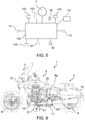
Figure 5 shows a functional block diagram of one exemplary embodiment of one electronic control unit of the motorcycle ofFigure 1 ; -
Figure 6 shows a side view of one possible embodiment of a motorcycle alternative to the one ofFigure 1 . - In the enclosed figures, same or similar elements will be indicated by the same reference numbers.
- In the enclosed
figures 1-4 one embodiment of amotorcycle 1 is shown, that in the specific represented example, is embodied, without limitation, by a two-wheel motorcycle and in particular a two-wheel scooter, having afront wheel 5 and arear wheel 6. - In the hereinafter description reference will be made to a
generic motorcycle 1, thereby meaning that the following description is applicable in general to any type ofmotorcycle 1 of Category L including: - a
motorcycle body - at least two
wheels motorcycle body - a
traction engine 7, e.g. thermal or electric or hybrid, constrained to themotorcycle body wheels - For example the
aforesaid motorcycle 1 is a two-wheel motorcycle, as for example a scooter or a motorbike, or a three-wheel motorcycle whereof at least two front wheels are steering and tilting, or a quadricycle provided with two pairs of tilting wheels and at least two steering wheels. - The
motorcycle body motorcycle 1, and has afront part 2, atail part 4 and acentral part 3 comprised between thefront part 2 and thetail part 4. Thecentral part 3 represents the part of themotorcycle 1 where the body of the driver is arranged mounting themotorcycle 1 or riding themotorcycle 1 in a normal condition of use of themotorcycle 1. In the example, the central part includes aplatform 35, a support placed under thesaddle 36, and afront portion 37 of the saddle. In the example, thefront part 2 includes afront shield 21, asteering handlebar 22, thefront wheel 5, afront mudguard 23. In the example, therear part 4, includes aback portion 47 of the saddle, astorage container 45, one or twoback suspensions 41, theback wheel 6 , thetraction engine 7. - The
motorcycle 1 includes at least afront headlight 12 fixed to thefront part 2 and at least oneback light 14 fixed to thetail part 4 and directed towards an opposite direction with respect to theheadlight 12. When thesteering handlebar 22 is not rotated, that is, when both thefront wheel 5 and theback wheel 6 are aligned along the longitudinal axis L-L, theheadlight 12 is such to emit an optical beam mainly centred along the longitudinal axis L-L and headed towards a ground portion arranged at the front with respect to themotorcycle 1. Therear light 14 is such to emit an optical non-orientable radiation, usually concentrated at the same height of the rear light thereof in order to avoid to dazzle vehicles that follow themotorcycle 1. - The
motorcycle 1 also includes a firstauxiliary lighting device 30 fixed to themotorcycle body auxiliary lighting device 30 is arranged and oriented so that, when activated, it lights a ground portion G1 being on the side and/or under thecentral part 3 of themotorcycle body auxiliary lighting device 30 is arranged and oriented in such a way that, when activated, it selectively lights the aforesaid portion of ground G1. For the purposes of the present invention by selectively it is meant mainly or exclusively. Preferably, the firstauxiliary lighting device 30 is arranged on themotorcycle body 1 in the middle, or substantially in the middle, between thefront wheel 5 and therear wheel 6. - According to one advantageous embodiment, the first
auxiliary lighting device 30 is arranged in thecentral part 3 of the body of themotorcycle 1 and it is oriented towards the ground. In one example consistent with the embodiment represented in the Figures, themotorcycle 1 is a scooter and thecentral part 3 of themotorcycle body platform 35 and the firstauxiliary lighting device 30 is placed beneath theplatform 35, in particular below a step up wall of theplatform 35. - Preferably the first
auxiliary lighting device 30 has a main emission optical axis D1 being oriented in a direction transversal to the longitudinal axis L-L and facing the ground. This can be obtained using a direct optical source, as for example a LED, and/or using an optical system for example including at least one lens and/or at least one spotlight able to spatially shape the optical radiation emitted by a non-direct optical source, as for example an incandescent light or a halogen light. Preferably, the aforesaid optical source cannot be seen looking at themotorcycle 1 from an observation point behind themotorcycle 1 along the longitudinal axis L-L when the motorcycle is running. - The
motorcycle 1 includes anelectronic control unit 100 operatively connected to the firstauxiliary lighting device 30 in order to activate and deactivate it. Theelectronic control unit 100, in a not claimed embodiment, is such to automatically activate thefirst lighting device 30 when the speed of themotorcycle 1 is lower than a threshold speed. Conveniently, in a not claimed embodiment, the threshold speed has an absolute value higher than zero. For example, the threshold speed is equal to 10 km/h or equal to 5 km/h. According to one embodiment, referring toFigure 5 , theelectronic control unit 100 is such to receive, for example from aspeed sensor 102 mounted on board themotorcycle 1 or connected operatively thereof, an electric signal bearing information related to themotorcycle speed 1. - For example, the
electronic control unit 100, as well as the firstauxiliary lighting device 30, is fed by onebattery 101 of themotorcycle 1. - Always referring to
Figure 5 , according to a non-limiting embodiment, theelectronic control unit 100 is the ECU (Engine Control Unit) of themotorcycle 1 and is such that it controls thetraction motor 7 too of themotorcycle 1. - According to one advantageous and non-limiting embodiment, the first
auxiliary lighting device 30 includes one pair of auxiliary lighting devices placed at opposite sides between them with respect to the longitudinal axis L-L. - According to an advantageous embodiment, the
motorcycle 1 also includes atwilight sensor 105 operatively connected to theelectronic control unit 100. Theelectronic control unit 100 is programmed to keep the firstauxiliary lighting device 30 off, regardless of the speed of themotorcycle 1, to the detection of a certain degree of ambient lighting. Thereby, it is possible to avoid to activate the firstauxiliary lighting device 30 when not required by circumstances. - According to the claimed embodiment, the
motorcycle 1 includes oneradio interface 103 operatively connected to theelectronic control unit 100. Theelectronic control unit 100 is programmed to activate the firstauxiliary lighting device 30 when the speed of themotorcycle 1 is equal to zero and when it receives a radio control signal from theradio interface 103. Thereby, it will be advantageously possible to use the firstauxiliary lighting device 30 also to enable the authorized user of themotorcycle 1 to detect the parking position of themotorcycle 1 when it is dark and from a certain distance. Theaforesaid radio interface 103 is for example an interface of a wireless portable device authorizing the use of themotorcycle 1, as for example an alarm controller and/or a keyfob. - According to one advantageous and non-limiting embodiment, the
motorcycle 1 includes at least onekickstand 10 adapted to be moved in order to selectively assume a resting operating position and a working operating position, wherein, in the working operating position, the kickstand has at least one end portion leaning against a ground portion being placed laterally and/or under the motorcycle body. Preferably, in such embodiment, themotorcycle 1 includes also one secondauxiliary lighting device 50 adapted to light thekickstand 10 or render it luminous. It must be noted that in theFigures 1 and4 thekickstand 10 is shown in the operative working position while inFigure 3 it is shown in the resting operative position. - According to one preferred embodiment, the second
auxiliary lighting device 50 is such as to light the kickstand 10 or render it luminous when thekickstand 10 is in the resting position. For example, it can be observed from the example ofFigures 3 and 4 that the second auxiliary lighting device is such that it lights amotorcycle 1 portion M and in particular of the tail part of themotorcycle 1 and more precisely one portion M1 of thetraction motor 7. Though it is convenient that thesecond lighting device 50 lights the kickstand 10 or renders it luminous when it is in the resting position, it is however possible to provide that the secondauxiliary lighting device 50 is such as to light the kickstand 10 or render it luminous when it is in the working position. - According to one advantageous embodiment, the second
auxiliary lighting device 50 is operatively connected to theelectronic control unit 100 in order to be activated and deactivated by it, and theelectronic control unit 100 is such to activate the secondauxiliary lighting device 50 when the speed of the vehicle is equal to zero and/or when thetraction engine 7 changes from an on-state to an off-state and/or when the driver getting off from themotorcycle 1 is detected. - According to one non-limiting embodiment, the second
auxiliary lighting device 50 is integrated in thekickstand 10, thereby it is such as to render the kickstand luminous. According to one embodiment alternative to the one above described, the secondauxiliary lighting device 50 is external to the kickstand, it is fastened to thebody motorcycle 1 and it is oriented towards the kickstand when said kickstand is in the resting position, thereby it is such as to render the kickstand luminous. - On the basis of what above described it is thus possible to understand that the motorcycle of the above described type enables to reach the aforementioned objects referring to the prior art state. In fact thanks to the first lighting device 30 a driver can see a portion of ground underlying the motorcycle and/or placed laterally with respect to the
motorcycle 1 and choose the most suitable area where to stop and park the motorcycle or simply where to place his feet, so that hazards due to the presence of holes, puddles, cutting objects as glass fragments, stones of uneven floor are avoided. - The above described embodiment is particularly advantageous wherein the first
auxiliary lighting device 30 is automatically activated when it detects that the motorcycle speed drops from any positive value below a certain threshold value, so that it activates automatically the aforesaid firstauxiliary lighting device 30 when it is likely that the driver is executing a stopping and/or parking operation of themotorcycle 1. - It is possible to provide that, after being activated, the first
auxiliary lighting device 30 is automatically deactivated if an event occurs or if it is time-controlled, for example under the control of theelectronic control unit 100. It is possible to provide that the motorcycle includes a device adapted to detect the presence of the driver on the motorcycle (called "driver presence sensor 106") operatively connected to theelectronic control unit 100 and that it is such as to deactivate the firstauxiliary lighting device 30 when it detects that the driver has got off themotorcycle 1 or after a time lapse from such detection. One non-limiting example ofdriver presence sensor 106 is described in PatentEP2130713 B1 , by the same Applicant. - Referring to
Figures 3 and 4 , in case the aforesaiddriver presence sensor 106 is present, such device may be for example used to establish the activation of the secondauxiliary lighting device 50, if the latter is provided in themotorcycle 1, for example in order to deactivate the firstauxiliary lighting device 30 and activate thesecond lighting device 50 when the driver gets off themotorcycle 1, thus passing from configuration ofFigure 3 to configuration ofFigure 4 . - One alternative embodiment of the motorcycle of
Figure 1 is shown inFigure 6 . The motorcycle ofFigure 6 is a motorcycle and includes the firstauxiliary lighting device 30 which is fixed toplatform 35, in particular below the step up wall of theplatform 35. It is possible to provide two firstauxiliary lighting devices 30, one of which is fixed to theplatform 35 of the right side of themotorcycle 1 and the other which is fixed to theplatform 35 of the left side. Optionally, as illustrated inFigure 6 , in thismotorcycle 1 too it is possible to provide the secondauxiliary lighting device 50 adapted to light thekickstand 10 or render it luminous. - Without prejudice to the principle of the invention, the embodiments and the implementation details shall be widely varied with respect to what has been described and illustrated for exemplary purposes, without departing from the scope of the invention as defined in the enclosed claims.
Claims (11)
- A motorcycle (1) including:- a motorcycle body (2, 3, 4) extending along a longitudinal axis (L-L) and having a front part (2), a tail part (4) and a central part (3) comprised between the front part (2) and the tail part (4);- at least two wheels (5, 6) constrained to the motorcycle body (2, 3, 4), including a front wheel (5) and a rear wheel (6);- a traction engine (7) constrained to the motorcycle body (2, 3, 4) and operatively connected to at least one of the wheels (5, 6);- at least one headlight (12) fixed to the front part (2) ;- at least one rear light (14) fixed to the tail part (4) ;- a first auxiliary lighting device (30) fixed to the motorcycle body (2, 3, 4) and adapted to be electrically controlled in order to be activated and deactivated, wherein the first auxiliary lighting device (30) is arranged and oriented so that, when activated, it lights a ground portion (G1) being on the side and/or under the central part (3) of the motorcycle body (2, 3, 4);- an electronic control unit (100) operatively connected to the first auxiliary lighting device (30) in order to activate and deactivate it; characterized by- a radio interface (103) operatively connected to the electronic control unit (100), wherein the electronic control unit (100) is programmed to activate the first auxiliary lighting device (30) when the speed of the motorcycle (1) is equal to zero and when receiving a radio control signal from said radio interface (103).
- The motorcycle (1) according to claim 1, wherein the first auxiliary lighting device (30) is arranged in the central part (3) and it is oriented towards the ground.
- The motorcycle (1) according to any one of the preceding claims, wherein the first auxiliary lighting device (30) has a main emission optical axis (D1) being oriented in a direction transversal to the longitudinal axis (L-L) and facing the ground.
- The motorcycle (1) according to any one of the preceding claims, wherein said central part (3) includes a platform (35) and wherein the first auxiliary lighting device (30) is placed under the platform (35).
- The motorcycle (1) according to claim 1, also including a twilight sensor (105) operatively connected to the electronic control unit (100) and wherein the electronic control unit (100) is programmed to keep the first auxiliary lighting device (30) off when detecting a certain degree of ambient lighting, regardless of the speed of the motorcycle (1).
- The motorcycle (1) according to any one of the preceding claims, wherein the first auxiliary lighting device (30) includes two auxiliary lighting devices being placed on opposite sides with respect to the longitudinal axis (L-L).
- The motorcycle (1) according to any one of the preceding claims, including at least one kickstand (10) adapted to be moved in order to selectively assume a resting operating position and a working operating position, wherein, in the working operating position, the kickstand has at least one end portion leaning against a ground portion being placed laterally and/or under the body of the motorcycle (1), also including a second auxiliary lighting device (50) adapted to light the kickstand (10) or to render it luminous.
- The motorcycle (1) according to claim 7, wherein the second auxiliary lighting device (50) is such to light the kickstand (10) when the kickstand is in the resting position.
- The motorcycle (1) according to claim 7, wherein the second auxiliary lighting device (50) is operatively connected to the electronic control unit (100) in order to be thereby activated and deactivated, and wherein the electronic control unit (100) is such to activate the second auxiliary lighting device (50) when the speed of the motorcycle (1) is equal to zero and/or the traction engine (7) changes from an on state to an off state and/or the driver getting off from the motorcycle (1) is detected.
- The motorcycle (1) according to claim 7, wherein the second auxiliary lighting device (50) is integrated in the kickstand (10).
- The motorcycle (1) according to claim 7, wherein the second auxiliary lighting device (50) is external to the kickstand, it is fixed to the body (2, 3, 4) of the motorcycle (1) and it is oriented towards the kickstand (10) when the kickstand is in the resting position.
Applications Claiming Priority (2)
| Application Number | Priority Date | Filing Date | Title |
|---|---|---|---|
| ITUA2016A004715A ITUA20164715A1 (en) | 2016-06-28 | 2016-06-28 | Motorcycle comprising an auxiliary lighting device |
| PCT/IB2017/053088 WO2018002741A1 (en) | 2016-06-28 | 2017-05-25 | Motorcycle comprising an auxiliary lighting device |
Publications (2)
| Publication Number | Publication Date |
|---|---|
| EP3475150A1 EP3475150A1 (en) | 2019-05-01 |
| EP3475150B1 true EP3475150B1 (en) | 2020-11-04 |
Family
ID=57750426
Family Applications (1)
| Application Number | Title | Priority Date | Filing Date |
|---|---|---|---|
| EP17737045.9A Active EP3475150B1 (en) | 2016-06-28 | 2017-05-25 | Motorcycle comprising an auxiliary lighting device |
Country Status (10)
| Country | Link |
|---|---|
| US (1) | US10654403B2 (en) |
| EP (1) | EP3475150B1 (en) |
| JP (1) | JP6993362B2 (en) |
| CN (1) | CN109311519A (en) |
| ES (1) | ES2848313T3 (en) |
| IL (1) | IL263951B2 (en) |
| IT (1) | ITUA20164715A1 (en) |
| MX (1) | MX2018016240A (en) |
| TW (1) | TWI715781B (en) |
| WO (1) | WO2018002741A1 (en) |
Families Citing this family (4)
| Publication number | Priority date | Publication date | Assignee | Title |
|---|---|---|---|---|
| US11312437B2 (en) * | 2019-05-28 | 2022-04-26 | John Joseph Rizzi | Adjustable system for stabilizing a bicycle |
| FR3103756A1 (en) * | 2019-12-01 | 2021-06-04 | jean luc bordel mathiolon | AUTOMATIC LIGHTING DEVICE FOR TWO WHEEL VEHICLE STAND |
| JP7050846B2 (en) * | 2020-03-31 | 2022-04-08 | 本田技研工業株式会社 | Rear fender structure of saddle-riding vehicle |
| WO2024003925A1 (en) * | 2022-06-27 | 2024-01-04 | Tvs Motor Company Limited | A system and method for illuminating surface of ground surrounding a periphery of a vehicle |
Citations (1)
| Publication number | Priority date | Publication date | Assignee | Title |
|---|---|---|---|---|
| US20080088423A1 (en) * | 2006-10-11 | 2008-04-17 | Yung-Lung Liu | Control and display for wireless signal light |
Family Cites Families (22)
| Publication number | Priority date | Publication date | Assignee | Title |
|---|---|---|---|---|
| JPS61150879A (en) * | 1984-12-24 | 1986-07-09 | ヤマハ発動機株式会社 | Saddling type seat for car |
| JPH01173095U (en) * | 1988-05-27 | 1989-12-07 | ||
| JPH0390443A (en) * | 1989-08-31 | 1991-04-16 | Honda Motor Co Ltd | Control device for vehicle |
| JP3360767B2 (en) * | 1994-05-24 | 2002-12-24 | スズキ株式会社 | Lighting structure of motorcycle |
| JPH10273081A (en) * | 1997-03-31 | 1998-10-13 | Sanyo Electric Co Ltd | Lighting system for bicycle |
| US20030197606A1 (en) * | 2002-04-22 | 2003-10-23 | Aaron Epstein | Vehicle rear light warning system |
| US20060077678A1 (en) * | 2004-10-12 | 2006-04-13 | Wen-Sung Chen | Automatic light and vibration sensing bicycle lamp |
| CN1718476A (en) * | 2005-07-23 | 2006-01-11 | 张成斌 | Automobile safety lighting device |
| US20070223240A1 (en) * | 2006-03-10 | 2007-09-27 | Clifton Brown | Auxiliary light assembly for a motorcycle |
| ITMI20081011A1 (en) | 2008-06-03 | 2009-12-04 | Piaggio & C Spa | DETECTION SYSTEM OF THE EMPLOYEE OF A VEHICLE SEAT |
| JP2010030470A (en) * | 2008-07-29 | 2010-02-12 | Honda Motor Co Ltd | Motorcycle |
| CN201264558Y (en) * | 2008-08-04 | 2009-07-01 | 王建中 | Floor irradiating lamp on automobile rearview mirror |
| CN201265784Y (en) * | 2008-08-04 | 2009-07-01 | 王建中 | Ground-lighting lamp of automobile door handle |
| US20140218521A1 (en) * | 2011-09-28 | 2014-08-07 | Toyota Jidosha Kabushiki Kaisha | Vehicle equipped with means for illuminating/watching a side area thereof |
| US8550673B1 (en) * | 2012-01-19 | 2013-10-08 | William C. Jones, Jr. | Secondary lighting system for motorcycles |
| JP2013248990A (en) | 2012-05-31 | 2013-12-12 | Yamaha Motor Co Ltd | Sub headlight unit for vehicle turning by lean attitude, vehicle component part and sub headlight system and vehicle turning by lean attitude |
| JP2014118135A (en) * | 2012-12-18 | 2014-06-30 | Nippon Lock:Kk | Motorcycle foot lighting device |
| JP2015071386A (en) * | 2013-10-04 | 2015-04-16 | 矢崎総業株式会社 | Vehicular lighting device |
| CN204056096U (en) | 2014-07-01 | 2014-12-31 | 昆山冠铼精密金属制品有限公司 | With the bicycle parking rack of lighting semaphore |
| TWM511966U (en) * | 2015-05-13 | 2015-11-11 | hui-sheng Wang | Removable multi-functional welcome, warning, security lighting projection lamp for motor vehicle |
| CN205186386U (en) * | 2015-07-31 | 2016-04-27 | 江苏跃进摩托车制造有限责任公司 | Tricycle of full angle illumination |
| JP2017074820A (en) * | 2015-10-13 | 2017-04-20 | スズキ株式会社 | Notification system for vehicle |
-
2016
- 2016-06-28 IT ITUA2016A004715A patent/ITUA20164715A1/en unknown
-
2017
- 2017-05-25 ES ES17737045T patent/ES2848313T3/en active Active
- 2017-05-25 US US16/312,944 patent/US10654403B2/en active Active
- 2017-05-25 MX MX2018016240A patent/MX2018016240A/en unknown
- 2017-05-25 JP JP2018568302A patent/JP6993362B2/en active Active
- 2017-05-25 EP EP17737045.9A patent/EP3475150B1/en active Active
- 2017-05-25 WO PCT/IB2017/053088 patent/WO2018002741A1/en unknown
- 2017-05-25 CN CN201780038782.XA patent/CN109311519A/en active Pending
- 2017-06-16 TW TW106120146A patent/TWI715781B/en active
-
2018
- 2018-12-24 IL IL263951A patent/IL263951B2/en unknown
Patent Citations (1)
| Publication number | Priority date | Publication date | Assignee | Title |
|---|---|---|---|---|
| US20080088423A1 (en) * | 2006-10-11 | 2008-04-17 | Yung-Lung Liu | Control and display for wireless signal light |
Also Published As
| Publication number | Publication date |
|---|---|
| TWI715781B (en) | 2021-01-11 |
| IL263951A (en) | 2019-01-31 |
| JP2019524531A (en) | 2019-09-05 |
| ITUA20164715A1 (en) | 2017-12-28 |
| JP6993362B2 (en) | 2022-01-13 |
| MX2018016240A (en) | 2019-04-22 |
| WO2018002741A1 (en) | 2018-01-04 |
| TW201811599A (en) | 2018-04-01 |
| CN109311519A (en) | 2019-02-05 |
| US10654403B2 (en) | 2020-05-19 |
| EP3475150A1 (en) | 2019-05-01 |
| IL263951B2 (en) | 2023-05-01 |
| IL263951B1 (en) | 2023-01-01 |
| ES2848313T3 (en) | 2021-08-06 |
| US20190337444A1 (en) | 2019-11-07 |
Similar Documents
| Publication | Publication Date | Title |
|---|---|---|
| EP3475150B1 (en) | Motorcycle comprising an auxiliary lighting device | |
| US9165460B2 (en) | Pedestrian warning light system for vehicles with illumination in different directions | |
| US8550673B1 (en) | Secondary lighting system for motorcycles | |
| EP3475151B1 (en) | Motorcycle including an auxiliary lighting device for parking operations | |
| IL267651B (en) | System and method for metal-air anode renovation | |
| JP2019524531A5 (en) | ||
| ES2808949T3 (en) | Motorcycle with electronic control of hazard lights | |
| JP6780465B2 (en) | Parking / stopping lighting device for saddle-type vehicles | |
| EP3494010B1 (en) | Vehicle with controllable brake light and electronic control method of the brake light | |
| KR101596322B1 (en) | A vehicle side lights device | |
| JPWO2018025109A5 (en) |
Legal Events
| Date | Code | Title | Description |
|---|---|---|---|
| STAA | Information on the status of an ep patent application or granted ep patent |
Free format text: STATUS: UNKNOWN |
|
| STAA | Information on the status of an ep patent application or granted ep patent |
Free format text: STATUS: THE INTERNATIONAL PUBLICATION HAS BEEN MADE |
|
| PUAI | Public reference made under article 153(3) epc to a published international application that has entered the european phase |
Free format text: ORIGINAL CODE: 0009012 |
|
| STAA | Information on the status of an ep patent application or granted ep patent |
Free format text: STATUS: REQUEST FOR EXAMINATION WAS MADE |
|
| 17P | Request for examination filed |
Effective date: 20181207 |
|
| AK | Designated contracting states |
Kind code of ref document: A1 Designated state(s): AL AT BE BG CH CY CZ DE DK EE ES FI FR GB GR HR HU IE IS IT LI LT LU LV MC MK MT NL NO PL PT RO RS SE SI SK SM TR |
|
| AX | Request for extension of the european patent |
Extension state: BA ME |
|
| DAV | Request for validation of the european patent (deleted) | ||
| DAX | Request for extension of the european patent (deleted) | ||
| STAA | Information on the status of an ep patent application or granted ep patent |
Free format text: STATUS: EXAMINATION IS IN PROGRESS |
|
| 17Q | First examination report despatched |
Effective date: 20191011 |
|
| GRAP | Despatch of communication of intention to grant a patent |
Free format text: ORIGINAL CODE: EPIDOSNIGR1 |
|
| STAA | Information on the status of an ep patent application or granted ep patent |
Free format text: STATUS: GRANT OF PATENT IS INTENDED |
|
| INTG | Intention to grant announced |
Effective date: 20200728 |
|
| GRAS | Grant fee paid |
Free format text: ORIGINAL CODE: EPIDOSNIGR3 |
|
| GRAA | (expected) grant |
Free format text: ORIGINAL CODE: 0009210 |
|
| STAA | Information on the status of an ep patent application or granted ep patent |
Free format text: STATUS: THE PATENT HAS BEEN GRANTED |
|
| AK | Designated contracting states |
Kind code of ref document: B1 Designated state(s): AL AT BE BG CH CY CZ DE DK EE ES FI FR GB GR HR HU IE IS IT LI LT LU LV MC MK MT NL NO PL PT RO RS SE SI SK SM TR |
|
| REG | Reference to a national code |
Ref country code: GB Ref legal event code: FG4D |
|
| REG | Reference to a national code |
Ref country code: CH Ref legal event code: EP |
|
| REG | Reference to a national code |
Ref country code: AT Ref legal event code: REF Ref document number: 1330482 Country of ref document: AT Kind code of ref document: T Effective date: 20201115 |
|
| REG | Reference to a national code |
Ref country code: IE Ref legal event code: FG4D |
|
| REG | Reference to a national code |
Ref country code: DE Ref legal event code: R096 Ref document number: 602017026857 Country of ref document: DE |
|
| REG | Reference to a national code |
Ref country code: NL Ref legal event code: FP |
|
| REG | Reference to a national code |
Ref country code: AT Ref legal event code: MK05 Ref document number: 1330482 Country of ref document: AT Kind code of ref document: T Effective date: 20201104 |
|
| PG25 | Lapsed in a contracting state [announced via postgrant information from national office to epo] |
Ref country code: NO Free format text: LAPSE BECAUSE OF FAILURE TO SUBMIT A TRANSLATION OF THE DESCRIPTION OR TO PAY THE FEE WITHIN THE PRESCRIBED TIME-LIMIT Effective date: 20210204 Ref country code: RS Free format text: LAPSE BECAUSE OF FAILURE TO SUBMIT A TRANSLATION OF THE DESCRIPTION OR TO PAY THE FEE WITHIN THE PRESCRIBED TIME-LIMIT Effective date: 20201104 Ref country code: PT Free format text: LAPSE BECAUSE OF FAILURE TO SUBMIT A TRANSLATION OF THE DESCRIPTION OR TO PAY THE FEE WITHIN THE PRESCRIBED TIME-LIMIT Effective date: 20210304 Ref country code: FI Free format text: LAPSE BECAUSE OF FAILURE TO SUBMIT A TRANSLATION OF THE DESCRIPTION OR TO PAY THE FEE WITHIN THE PRESCRIBED TIME-LIMIT Effective date: 20201104 Ref country code: GR Free format text: LAPSE BECAUSE OF FAILURE TO SUBMIT A TRANSLATION OF THE DESCRIPTION OR TO PAY THE FEE WITHIN THE PRESCRIBED TIME-LIMIT Effective date: 20210205 |
|
| PG25 | Lapsed in a contracting state [announced via postgrant information from national office to epo] |
Ref country code: AT Free format text: LAPSE BECAUSE OF FAILURE TO SUBMIT A TRANSLATION OF THE DESCRIPTION OR TO PAY THE FEE WITHIN THE PRESCRIBED TIME-LIMIT Effective date: 20201104 Ref country code: BG Free format text: LAPSE BECAUSE OF FAILURE TO SUBMIT A TRANSLATION OF THE DESCRIPTION OR TO PAY THE FEE WITHIN THE PRESCRIBED TIME-LIMIT Effective date: 20210204 Ref country code: PL Free format text: LAPSE BECAUSE OF FAILURE TO SUBMIT A TRANSLATION OF THE DESCRIPTION OR TO PAY THE FEE WITHIN THE PRESCRIBED TIME-LIMIT Effective date: 20201104 Ref country code: LV Free format text: LAPSE BECAUSE OF FAILURE TO SUBMIT A TRANSLATION OF THE DESCRIPTION OR TO PAY THE FEE WITHIN THE PRESCRIBED TIME-LIMIT Effective date: 20201104 Ref country code: IS Free format text: LAPSE BECAUSE OF FAILURE TO SUBMIT A TRANSLATION OF THE DESCRIPTION OR TO PAY THE FEE WITHIN THE PRESCRIBED TIME-LIMIT Effective date: 20210304 Ref country code: SE Free format text: LAPSE BECAUSE OF FAILURE TO SUBMIT A TRANSLATION OF THE DESCRIPTION OR TO PAY THE FEE WITHIN THE PRESCRIBED TIME-LIMIT Effective date: 20201104 |
|
| REG | Reference to a national code |
Ref country code: LT Ref legal event code: MG9D |
|
| PG25 | Lapsed in a contracting state [announced via postgrant information from national office to epo] |
Ref country code: HR Free format text: LAPSE BECAUSE OF FAILURE TO SUBMIT A TRANSLATION OF THE DESCRIPTION OR TO PAY THE FEE WITHIN THE PRESCRIBED TIME-LIMIT Effective date: 20201104 |
|
| PG25 | Lapsed in a contracting state [announced via postgrant information from national office to epo] |
Ref country code: RO Free format text: LAPSE BECAUSE OF FAILURE TO SUBMIT A TRANSLATION OF THE DESCRIPTION OR TO PAY THE FEE WITHIN THE PRESCRIBED TIME-LIMIT Effective date: 20201104 Ref country code: SK Free format text: LAPSE BECAUSE OF FAILURE TO SUBMIT A TRANSLATION OF THE DESCRIPTION OR TO PAY THE FEE WITHIN THE PRESCRIBED TIME-LIMIT Effective date: 20201104 Ref country code: CZ Free format text: LAPSE BECAUSE OF FAILURE TO SUBMIT A TRANSLATION OF THE DESCRIPTION OR TO PAY THE FEE WITHIN THE PRESCRIBED TIME-LIMIT Effective date: 20201104 Ref country code: EE Free format text: LAPSE BECAUSE OF FAILURE TO SUBMIT A TRANSLATION OF THE DESCRIPTION OR TO PAY THE FEE WITHIN THE PRESCRIBED TIME-LIMIT Effective date: 20201104 Ref country code: LT Free format text: LAPSE BECAUSE OF FAILURE TO SUBMIT A TRANSLATION OF THE DESCRIPTION OR TO PAY THE FEE WITHIN THE PRESCRIBED TIME-LIMIT Effective date: 20201104 Ref country code: SM Free format text: LAPSE BECAUSE OF FAILURE TO SUBMIT A TRANSLATION OF THE DESCRIPTION OR TO PAY THE FEE WITHIN THE PRESCRIBED TIME-LIMIT Effective date: 20201104 |
|
| REG | Reference to a national code |
Ref country code: DE Ref legal event code: R097 Ref document number: 602017026857 Country of ref document: DE |
|
| REG | Reference to a national code |
Ref country code: ES Ref legal event code: FG2A Ref document number: 2848313 Country of ref document: ES Kind code of ref document: T3 Effective date: 20210806 |
|
| PG25 | Lapsed in a contracting state [announced via postgrant information from national office to epo] |
Ref country code: DK Free format text: LAPSE BECAUSE OF FAILURE TO SUBMIT A TRANSLATION OF THE DESCRIPTION OR TO PAY THE FEE WITHIN THE PRESCRIBED TIME-LIMIT Effective date: 20201104 |
|
| PLBE | No opposition filed within time limit |
Free format text: ORIGINAL CODE: 0009261 |
|
| STAA | Information on the status of an ep patent application or granted ep patent |
Free format text: STATUS: NO OPPOSITION FILED WITHIN TIME LIMIT |
|
| 26N | No opposition filed |
Effective date: 20210805 |
|
| PG25 | Lapsed in a contracting state [announced via postgrant information from national office to epo] |
Ref country code: AL Free format text: LAPSE BECAUSE OF FAILURE TO SUBMIT A TRANSLATION OF THE DESCRIPTION OR TO PAY THE FEE WITHIN THE PRESCRIBED TIME-LIMIT Effective date: 20201104 |
|
| PG25 | Lapsed in a contracting state [announced via postgrant information from national office to epo] |
Ref country code: SI Free format text: LAPSE BECAUSE OF FAILURE TO SUBMIT A TRANSLATION OF THE DESCRIPTION OR TO PAY THE FEE WITHIN THE PRESCRIBED TIME-LIMIT Effective date: 20201104 |
|
| REG | Reference to a national code |
Ref country code: CH Ref legal event code: PL |
|
| GBPC | Gb: european patent ceased through non-payment of renewal fee |
Effective date: 20210525 |
|
| PG25 | Lapsed in a contracting state [announced via postgrant information from national office to epo] |
Ref country code: MC Free format text: LAPSE BECAUSE OF FAILURE TO SUBMIT A TRANSLATION OF THE DESCRIPTION OR TO PAY THE FEE WITHIN THE PRESCRIBED TIME-LIMIT Effective date: 20201104 Ref country code: LU Free format text: LAPSE BECAUSE OF NON-PAYMENT OF DUE FEES Effective date: 20210525 Ref country code: LI Free format text: LAPSE BECAUSE OF NON-PAYMENT OF DUE FEES Effective date: 20210531 Ref country code: CH Free format text: LAPSE BECAUSE OF NON-PAYMENT OF DUE FEES Effective date: 20210531 |
|
| REG | Reference to a national code |
Ref country code: BE Ref legal event code: MM Effective date: 20210531 |
|
| PG25 | Lapsed in a contracting state [announced via postgrant information from national office to epo] |
Ref country code: IE Free format text: LAPSE BECAUSE OF NON-PAYMENT OF DUE FEES Effective date: 20210525 Ref country code: GB Free format text: LAPSE BECAUSE OF NON-PAYMENT OF DUE FEES Effective date: 20210525 |
|
| PG25 | Lapsed in a contracting state [announced via postgrant information from national office to epo] |
Ref country code: IS Free format text: LAPSE BECAUSE OF FAILURE TO SUBMIT A TRANSLATION OF THE DESCRIPTION OR TO PAY THE FEE WITHIN THE PRESCRIBED TIME-LIMIT Effective date: 20210304 |
|
| PG25 | Lapsed in a contracting state [announced via postgrant information from national office to epo] |
Ref country code: BE Free format text: LAPSE BECAUSE OF NON-PAYMENT OF DUE FEES Effective date: 20210531 |
|
| PG25 | Lapsed in a contracting state [announced via postgrant information from national office to epo] |
Ref country code: CY Free format text: LAPSE BECAUSE OF FAILURE TO SUBMIT A TRANSLATION OF THE DESCRIPTION OR TO PAY THE FEE WITHIN THE PRESCRIBED TIME-LIMIT Effective date: 20201104 |
|
| P01 | Opt-out of the competence of the unified patent court (upc) registered |
Effective date: 20230529 |
|
| PG25 | Lapsed in a contracting state [announced via postgrant information from national office to epo] |
Ref country code: HU Free format text: LAPSE BECAUSE OF FAILURE TO SUBMIT A TRANSLATION OF THE DESCRIPTION OR TO PAY THE FEE WITHIN THE PRESCRIBED TIME-LIMIT; INVALID AB INITIO Effective date: 20170525 |
|
| PGFP | Annual fee paid to national office [announced via postgrant information from national office to epo] |
Ref country code: NL Payment date: 20230525 Year of fee payment: 7 Ref country code: IT Payment date: 20230405 Year of fee payment: 7 Ref country code: FR Payment date: 20230523 Year of fee payment: 7 Ref country code: ES Payment date: 20230601 Year of fee payment: 7 Ref country code: DE Payment date: 20230519 Year of fee payment: 7 |