EP3474580B1 - Information pushing method and device - Google Patents
Information pushing method and device Download PDFInfo
- Publication number
- EP3474580B1 EP3474580B1 EP17812586.0A EP17812586A EP3474580B1 EP 3474580 B1 EP3474580 B1 EP 3474580B1 EP 17812586 A EP17812586 A EP 17812586A EP 3474580 B1 EP3474580 B1 EP 3474580B1
- Authority
- EP
- European Patent Office
- Prior art keywords
- signal
- target object
- identification information
- user equipment
- information
- Prior art date
- Legal status (The legal status is an assumption and is not a legal conclusion. Google has not performed a legal analysis and makes no representation as to the accuracy of the status listed.)
- Active
Links
- 238000000034 method Methods 0.000 title claims description 88
- 238000013507 mapping Methods 0.000 claims description 70
- 230000002159 abnormal effect Effects 0.000 claims description 7
- 238000004364 calculation method Methods 0.000 claims description 4
- 238000012216 screening Methods 0.000 claims 1
- 238000010586 diagram Methods 0.000 description 12
- 238000004590 computer program Methods 0.000 description 9
- 238000005516 engineering process Methods 0.000 description 9
- 230000005540 biological transmission Effects 0.000 description 6
- 230000006870 function Effects 0.000 description 4
- 230000003287 optical effect Effects 0.000 description 3
- 230000001174 ascending effect Effects 0.000 description 2
- 238000001514 detection method Methods 0.000 description 2
- 230000003203 everyday effect Effects 0.000 description 2
- 230000009286 beneficial effect Effects 0.000 description 1
- 230000004069 differentiation Effects 0.000 description 1
- 230000003068 static effect Effects 0.000 description 1
Images


Classifications
-
- H—ELECTRICITY
- H04—ELECTRIC COMMUNICATION TECHNIQUE
- H04W—WIRELESS COMMUNICATION NETWORKS
- H04W4/00—Services specially adapted for wireless communication networks; Facilities therefor
- H04W4/02—Services making use of location information
-
- H—ELECTRICITY
- H04—ELECTRIC COMMUNICATION TECHNIQUE
- H04W—WIRELESS COMMUNICATION NETWORKS
- H04W4/00—Services specially adapted for wireless communication networks; Facilities therefor
- H04W4/02—Services making use of location information
- H04W4/023—Services making use of location information using mutual or relative location information between multiple location based services [LBS] targets or of distance thresholds
-
- H—ELECTRICITY
- H04—ELECTRIC COMMUNICATION TECHNIQUE
- H04W—WIRELESS COMMUNICATION NETWORKS
- H04W4/00—Services specially adapted for wireless communication networks; Facilities therefor
- H04W4/02—Services making use of location information
- H04W4/029—Location-based management or tracking services
-
- G—PHYSICS
- G01—MEASURING; TESTING
- G01S—RADIO DIRECTION-FINDING; RADIO NAVIGATION; DETERMINING DISTANCE OR VELOCITY BY USE OF RADIO WAVES; LOCATING OR PRESENCE-DETECTING BY USE OF THE REFLECTION OR RERADIATION OF RADIO WAVES; ANALOGOUS ARRANGEMENTS USING OTHER WAVES
- G01S5/00—Position-fixing by co-ordinating two or more direction or position line determinations; Position-fixing by co-ordinating two or more distance determinations
- G01S5/02—Position-fixing by co-ordinating two or more direction or position line determinations; Position-fixing by co-ordinating two or more distance determinations using radio waves
- G01S5/0252—Radio frequency fingerprinting
- G01S5/02521—Radio frequency fingerprinting using a radio-map
- G01S5/02524—Creating or updating the radio-map
- G01S5/02525—Gathering the radio frequency fingerprints
- G01S5/02526—Gathering the radio frequency fingerprints using non-dedicated equipment, e.g. user equipment or crowd-sourcing
-
- H—ELECTRICITY
- H04—ELECTRIC COMMUNICATION TECHNIQUE
- H04L—TRANSMISSION OF DIGITAL INFORMATION, e.g. TELEGRAPHIC COMMUNICATION
- H04L67/00—Network arrangements or protocols for supporting network services or applications
- H04L67/50—Network services
- H04L67/52—Network services specially adapted for the location of the user terminal
-
- H—ELECTRICITY
- H04—ELECTRIC COMMUNICATION TECHNIQUE
- H04L—TRANSMISSION OF DIGITAL INFORMATION, e.g. TELEGRAPHIC COMMUNICATION
- H04L67/00—Network arrangements or protocols for supporting network services or applications
- H04L67/50—Network services
- H04L67/55—Push-based network services
-
- H—ELECTRICITY
- H04—ELECTRIC COMMUNICATION TECHNIQUE
- H04W—WIRELESS COMMUNICATION NETWORKS
- H04W4/00—Services specially adapted for wireless communication networks; Facilities therefor
- H04W4/02—Services making use of location information
- H04W4/021—Services related to particular areas, e.g. point of interest [POI] services, venue services or geofences
-
- H—ELECTRICITY
- H04—ELECTRIC COMMUNICATION TECHNIQUE
- H04W—WIRELESS COMMUNICATION NETWORKS
- H04W48/00—Access restriction; Network selection; Access point selection
- H04W48/08—Access restriction or access information delivery, e.g. discovery data delivery
- H04W48/14—Access restriction or access information delivery, e.g. discovery data delivery using user query or user detection
-
- H—ELECTRICITY
- H04—ELECTRIC COMMUNICATION TECHNIQUE
- H04W—WIRELESS COMMUNICATION NETWORKS
- H04W48/00—Access restriction; Network selection; Access point selection
- H04W48/16—Discovering, processing access restriction or access information
-
- H—ELECTRICITY
- H04—ELECTRIC COMMUNICATION TECHNIQUE
- H04W—WIRELESS COMMUNICATION NETWORKS
- H04W48/00—Access restriction; Network selection; Access point selection
- H04W48/20—Selecting an access point
-
- H—ELECTRICITY
- H04—ELECTRIC COMMUNICATION TECHNIQUE
- H04W—WIRELESS COMMUNICATION NETWORKS
- H04W60/00—Affiliation to network, e.g. registration; Terminating affiliation with the network, e.g. de-registration
- H04W60/04—Affiliation to network, e.g. registration; Terminating affiliation with the network, e.g. de-registration using triggered events
-
- H—ELECTRICITY
- H04—ELECTRIC COMMUNICATION TECHNIQUE
- H04W—WIRELESS COMMUNICATION NETWORKS
- H04W64/00—Locating users or terminals or network equipment for network management purposes, e.g. mobility management
-
- H—ELECTRICITY
- H04—ELECTRIC COMMUNICATION TECHNIQUE
- H04W—WIRELESS COMMUNICATION NETWORKS
- H04W76/00—Connection management
- H04W76/10—Connection setup
- H04W76/11—Allocation or use of connection identifiers
Definitions
- the present application relates to the field of Internet information technologies, and in particular, to an information pushing method and a location positioning method and device.
- the user can enter a target object to be searched on an Internet platform, and the Internet platform can search based on the target object entered by the user, and display information about the identified target object to the user. Therefore, the user can conveniently obtain the information about the target object.
- the Internet platform can display, to the user based on current geographical location information of the user, information about a target object relatively close to the user.
- the user's current geographical location information can be determined through positioning; secondly, the target object relatively close to the user is determined based on the user's current geographical location information; and finally, the information about the determined target object relatively close to the user is displayed to the user. Therefore, the user can conveniently obtain the information about the target object relatively close to the user.
- the Internet platform can match user's geographical location information with address information of the target object, and determine the target object based on a matching result.
- the accuracy of the determined target object is relatively low as the matching accuracy is relatively low. Consequently, the information about the target object displayed to the user usually cannot satisfy an actual demand of the user, causing relatively poor user experience.
- US 8 233 913 B2 describes systems and methods for obtaining a signature for a place.
- a server receives information about a place, such as name of the place, from client devices when the devices are at the place, and data related to wireless transmission stations detected by the client devices.
- the data comprises wireless transmission station identifiers and signal strength information.
- the server associates the information about the place with the data.
- Also described are systems and methods for detecting a place for a client device.
- the server receives data related to one or more wireless transmission stations detected by the client device when the device is at the place.
- the data comprises wireless transmission station identifiers and signal strength information.
- the server compares the set of data with signatures of places, selects a signature based on the comparison, and transmits to the client device information about the place in the selected signature.
- US 8 385 943 B1 describes a method and apparatus for determining location information of a position in a multi-storey building.
- the method comprises: retrieving observation data comprising observed addresses and corresponding observed received signal strengths of wireless access points detected at the position from a memory; retrieving, for each storey of the building, a radio map comprising a plurality of location points in the respective storey of the building from a database, each location point comprising addresses and corresponding mean received signal strengths of wireless access points detected at the location point and coordinates of the location point; selecting one or more location points comprising the observed addresses from the radio map; determining a storey estimate of the position by calculating a sum probability for each storey of the building, the sum probability being calculated by summing all individual probabilities of each observed address contained in each selected location point in the radio map of the respective storey being detected on the respective storey; and setting the storey estimate as the storey of the building having highest value of the calculated sum probability, wherein each of said individual probabilities is calculated based on the corresponding observed received
- Implementations of the present application provide an information pushing method and a location positioning method and device, so as to alleviate an existing problem that user experience is relatively poor because information about a target object displayed to a user cannot satisfy an actual demand of the user.
- An implementation of the present application provides an information pushing method, including the following: obtaining feature information of a Wi-Fi signal detected by user equipment, where the feature information includes identification information of the Wi-Fi signal; searching a database for identification information of a target object corresponding to the identification information of the Wi-Fi signal, where the database includes a mapping relationship between identification information of a Wi-Fi signal and identification information of a target object covered by the Wi-Fi signal; and pushing the identified identification information of the target object to the user equipment.
- An implementation of the present application provides an information pushing device, including the following: an acquisition unit, configured to obtain feature information of a Wi-Fi signal detected by user equipment, where the feature information includes identification information of the Wi-Fi signal; a search unit, configured to search a database for identification information of a target object corresponding to the identification information of the Wi-Fi signal, where the database includes a mapping relationship between identification information of a Wi-Fi signal and identification information of a target object covered by the Wi-Fi signal; and a pushing unit, configured to push the identification information of the target object identified by the search unit to the user equipment.
- the identification information of the target object covered by the Wi-Fi signal is determined based on the feature information of the Wi-Fi signal that can be currently detected by the user equipment, and the determined identification information of the target object is pushed to the user equipment, so that the user of the user equipment can quickly obtain the identification information of the target object.
- coverage of the Wi-Fi signal is relatively small, the accuracy of the target object determined based on the Wi-Fi signal is relatively high, and information about the target object displayed to the user can satisfy an actual demand of the user, thereby effectively improving user experience.
- An implementation of the present application provides a location positioning method, including the following: obtaining feature information of a Wi-Fi signal detected by user equipment, where the feature information includes identification information of the Wi-Fi signal; searching a database for identification information of a target object corresponding to the identification information of the Wi-Fi signal, where the database includes a mapping relationship between identification information of a Wi-Fi signal and identification information of a target object covered by the Wi-Fi signal; determining an eigenvalue of the target object corresponding to the identification information, where the eigenvalue is used to represent a location relationship between the user equipment and the target object; and determining, based on the eigenvalue of the target object, whether a location of the user equipment is consistent with a location of the target object.
- An implementation of the present application provides a location positioning device, including the following: an acquisition unit, configured to obtain feature information of a Wi-Fi signal detected by user equipment, where the feature information includes identification information of the Wi-Fi signal; a search unit, configured to search a database for identification information of a target object corresponding to the identification information of the Wi-Fi signal, where the database includes a mapping relationship between identification information of a Wi-Fi signal and identification information of a target object covered by the Wi-Fi signal; a determining unit, configured to determine an eigenvalue of the target object corresponding to the identification information, where the eigenvalue is used to represent a location relationship between the user equipment and the target object; and a location determining unit, configured to determine, based on the eigenvalue of the target object, whether a location of the user equipment is consistent with a location of the target object.
- the identification information of the target object covered by the Wi-Fi signal is identified based on the feature information of the Wi-Fi signal detected by the user equipment, and the eigenvalue of the target object is determined, so as to determine the location of the user equipment based on the eigenvalue of the target object. Because coverage of the Wi-Fi signal is relatively small, the accuracy of the user equipment's location based on the Wi-Fi signal is relatively high.
- the Internet platform when an Internet platform is to display, to a user based on geographical location information of the user, information about a target object that is relatively close to the user, the Internet platform can match user's geographical location information and address information of the target object, and display the information about the target object to the user based on a matching result.
- the accuracy of the determined target object is relatively low as the matching accuracy is relatively low. For example, if a target object obtained through matching is actually relatively far away from the user, it is relatively difficult for the user to determine the actual location of the target object, causing relatively poor user experience.
- Wi-Fi Wireless Fidelity
- a personal computer and a handheld device for example, a Pad or a mobile phone
- Wi-Fi technologies are increasingly applied in various public places with the rapid development, for example, office places and shopping places.
- the user can search for a Wi-Fi signal provided by the public area to the outside with user equipment. After identifying the Wi-Fi signal, the user equipment can display a name of the Wi-Fi signal, and at this time, the user equipment can be connected to the Wi-Fi signal.
- a public area that the user is currently located in can be determined based on the connected Wi-Fi signal because the connected Wi-Fi signal is provided by the public place.
- the accuracy of the public area determined based on the Wi-Fi signal is relatively high because coverage of the Wi-Fi signal is relatively small.
- the Internet platform can determine, based on a Wi-Fi signal to which the user equipment is connected, a target object providing the Wi-Fi signal. Because the accuracy of a target object determined based on a Wi-Fi signal is relatively high, an actual demand of the user can be satisfied when the information about the target object is displayed to the user.
- whether the user arrives at the target object can be determined by using the Wi-Fi signal, to display the information about the target object to the user.
- Identification information of the Wi-Fi signal corresponding to the target object can be predetermined. Therefore, when detecting the Wi-Fi signal, the user equipment can determine the target object based on the Wi-Fi signal, and display the information about the target object to the user.
- the identification information of the Wi-Fi signal when determining the identification information of the Wi-Fi signal that corresponds to the target object, the identification information of the Wi-Fi signal is usually manually uploaded, or the Wi-Fi signal to which the user equipment is connected is usually obtained when the user makes a payment by scanning a QR code in the target object.
- efficiency of obtaining identification information of a Wi-Fi signal is relatively low, and the Wi-Fi signal of the target object cannot be updated in time when the target object changes the Wi-Fi signal.
- the method for obtaining a Wi-Fi signal during payment transaction is applicable only to a relatively large shop, and is applicable only to a target object provided with a Wi-Fi signal. Consequently, it is relatively difficult to determine the target object based on the Wi-Fi signal.
- the information about the target object covered by the Wi-Fi signal can be displayed to the user based on the Wi-Fi signal detected by the user equipment, so that the information about the target object that is provided for the user can satisfy the actual demand of the user, thereby improving user experience.
- the user does not need to manually upload the identification information of the Wi-Fi signal corresponding to the target object
- the Wi-Fi signal corresponding to the target object determined in the implementations of the present application can be a Wi-Fi signal provided by the target object to the outside, or can be another Wi-Fi signal that covers the target object. Therefore, provided that the target object can receive the Wi-Fi signal, the target object can be determined by using the Wi-Fi signal that covers the target object, thereby resolving the previous problem.
- the implementations of the present application provide an information pushing method and a location positioning method and device.
- Feature information of a Wi-Fi signal detected by user equipment is obtained, where the feature information includes identification information of the Wi-Fi signal; and identification information of a target object corresponding to the identification information of the Wi-Fi signal is identified from a database, where the database includes a mapping relationship between identification information of a Wi-Fi signal and identification information of a target object covered by the Wi-Fi signal; and the identified identification information of the target object is pushed to the user equipment.
- the identification information of the target object covered by the Wi-Fi signal is determined based on the feature information of the Wi-Fi signal that can be currently detected by the user equipment, and the determined identification information of the target object is pushed to the user equipment, so that a user of the user equipment can quickly obtain the identification information of the target object.
- coverage of the Wi-Fi signal is relatively small, the accuracy of the target object determined based on the Wi-Fi signal is relatively high, so that information about the target object displayed to the user can satisfy an actual demand of the user, thereby effectively improving user experience.
- the target object can be a shop.
- the technical solutions provided in the implementations of the present application can be used to determine a shop that the user is currently located in, and display information about the shop to the user; or can be used to determine a shop near a location of the user, and display information about the determined shop nearby to the user. No limitation is imposed here.
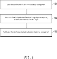
- FIG. 1 is a schematic flowchart illustrating an information pushing method, according to an implementation of the present application. The method includes the following steps.
- Step 101 Obtain feature information of a Wi-Fi signal detected by user equipment.
- the feature information includes identification information of the Wi-Fi signal.
- a user can detect, by using current user equipment, at least one Wi-Fi signal that covers the user equipment.
- the feature information of the Wi-Fi signal can be obtained based on the Wi-Fi signal detected by the user equipment.
- the user equipment is a device that can detect a Wi-Fi signal.
- the user equipment can be an intelligent terminal device such as a smartphone, a notebook computer, or an iPad, or can be another device that can detect a Wi-Fi signal, which is not limited.
- the user can enable a function control configured to detect a Wi-Fi signal in the user equipment.
- the user equipment can detect a Wi-Fi signal that covers the user equipment.
- a Wi-Fi name corresponding to the detected Wi-Fi signal can be displayed on the user equipment.
- the Wi-Fi name here is a name of a device (such as a wireless router) that transmits the Wi-Fi signal. In practice, the Wi-Fi name can be manually set.
- the user equipment can detect a Wi-Fi signal that covers the user equipment and that has a Wi-Fi name "XXXX", so that the Wi-Fi name "XXXX" corresponding to the Wi-Fi signal can be displayed on the user equipment when the user equipment detects the Wi-Fi signal corresponding to the Wi-Fi name.
- one or more Wi-Fi signals may cover the user equipment. If a plurality of Wi-Fi signals cover the user equipment, a Wi-Fi name corresponding to each detected Wi-Fi signal can be displayed on the user equipment after the user equipment detects the plurality of Wi-Fi signals.
- the feature information of the Wi-Fi signal can be obtained based on the Wi-Fi name displayed on the user equipment, where the feature information of the Wi-Fi signal can include the identification information of the Wi-Fi signal.
- the identification information of the Wi-Fi signal can be a Media Access Control (MAC) address corresponding to the Wi-Fi signal, or can be the Wi-Fi name corresponding to the Wi-Fi signal, which is not limited.
- the identification information of the Wi-Fi signal is the MAC address corresponding to the Wi-Fi signal.
- the feature information of the Wi-Fi signal can further include a signal strength of the Wi-Fi signal, and the signal strength of the Wi-Fi signal here is a signal strength of the Wi-Fi signal that can be received by the user equipment when the user equipment detects the Wi-Fi signal.
- a server After the user equipment detects the Wi-Fi signal, a server can obtain the feature information of the Wi-Fi signal.
- the server can obtain, at least by using the following methods, the feature information of the Wi-Fi signal detected by the user equipment.
- Method 1 When detecting the Wi-Fi signal and determining to establish a data connection to the server, the user equipment can send the feature information of the detected Wi-Fi signal to the server, so that the server can obtain the feature information of the Wi-Fi signal.
- the user equipment can establish the data connection to the server before or when detecting the Wi-Fi signal, which is not limited.
- Method 2 A data connection between a device (such as a wireless router) that transmits a Wi-Fi signal and the server can be established in advance.
- the device that transmits the Wi-Fi signal can determine the feature information of the Wi-Fi signal detected by the user equipment, and send the feature information of the Wi-Fi signal and a device identity of the user equipment to the server, so that the server can obtain the feature information of the Wi-Fi signal detected by the user equipment.
- the server can be a server corresponding to application software.
- the server can obtain, by using another method, the feature information of the Wi-Fi signal detected by the user equipment, which is not limited.
- the server can obtain the feature information of the Wi-Fi signal detected by the user equipment.
- Step 102 Search a database for identification information of a target object corresponding to identification information of the Wi-Fi signal.
- the database includes a mapping relationship between identification information of a Wi-Fi signal and identification information of a target object covered by the Wi-Fi signal.
- step 102 after the feature information of the Wi-Fi signal is obtained, the identification information of the target object corresponding to the identification information of the Wi-Fi signal can be identified from the database based on the identification information of the Wi-Fi signal included in the feature information, so as to push the identified identification information of the target object to the user equipment.
- the mapping relationship between identification information of a Wi-Fi signal and identification information of a target object covered by the Wi-Fi signal can be pre-stored in the database.
- the identification information of the Wi-Fi signal is obtained, the identification information of the target object corresponding to the identification information of the Wi-Fi signal can be identified from the database based on the identification information of the Wi-Fi signal.
- the database can be determined by using the following method, including the following steps.
- Step 1 Obtain feature information of the Wi-Fi signal that covers the target object, where the feature information of the Wi-Fi signal is included in a service request sent by a user, the feature information of the Wi-Fi signal includes the identification information of the Wi-Fi signal and the signal strength of the Wi-Fi signal, and the service request includes the identification information of the target object.
- the user can use the user equipment to detect the Wi-Fi signal in a location of the target object. Because the user is located in the target object, the Wi-Fi signal detected by the user equipment is the Wi-Fi signal that covers the target object. In this situation, the user can access the Internet by using the Wi-Fi signal, and send a service request related to the target object to the server.
- the service request can include the identification information of the target object and the feature information of the Wi-Fi signal that is connected to the user equipment and that covers the target object.
- the feature information can include the identification information of the Wi-Fi signal and the signal strength of the Wi-Fi signal.
- the signal strength of the Wi-Fi signal here is a signal strength of the Wi-Fi signal received by the user equipment when the user sends the service request.
- the Wi-Fi signal (namely, the Wi-Fi signal that covers the target object) detected by the user equipment can be a Wi-Fi signal provided by the target object to the outside, or can be another Wi-Fi signal (namely, another Wi-Fi signal that covers the target object) that can be received by the target object, which is not limited.
- the user equipment can be connected to one of the Wi-Fi signals, and add feature information of the connected Wi-Fi signal or feature information of the plurality of Wi-Fi signals that cover the target object to the service request when the user sends the service request, which is not limited.
- the obtained Wi-Fi signals can be screened to exclude abnormal Wi-Fi signals, such as Wi-Fi signals with an abnormal MAC address (for example, the MAC address is "00") or Wi-Fi signals with an abnormal Wi-Fi name (for example, the Wi-Fi name is "-").
- a strength range of Wi-Fi signals can be preset to exclude Wi-Fi signals with signal strengths exceeding the preset range, and the strength range of the Wi-Fi signals here can be manually set.
- the strength range can be from 0 dB to -120 dB.
- Step 2 Establish a mapping relationship between identification information of a target object, identification information of a Wi-Fi signal that covers the target object, and a signal strength of the Wi-Fi signal, and store the mapping relationship in the database.
- the mapping relationship between identification information of a target object, identification information of a Wi-Fi signal that covers the target object, and a signal strength of the Wi-Fi signal can be established after the feature information of the Wi-Fi signal that covers the target object is obtained.
- the mapping relationship between identification information of a target object, identification information of a Wi-Fi signal that covers the target object, and a signal strength of the Wi-Fi signal can be established based on the obtained feature information of the Wi-Fi signal.
- one or more Wi-Fi signals may be obtained based on the target object. Therefore, the following two situations can be separately analyzed when the mapping relationship is established.
- the identification information of the Wi-Fi signal, the identification information of the target object, and the signal strength of the Wi-Fi signal need to be determined when the mapping relationship is established.
- the identification information of the target object can be determined based on the service request sent by the user, and the identification information of the Wi-Fi signal can be determined based on the Wi-Fi signal.
- the signal strength of the Wi-Fi signal is determined, because signal strengths of Wi-Fi signals detected by user equipments can be different in practice, an average value of different signal strengths of the detected Wi-Fi signals can be calculated, and the calculated average value is used as the signal strength of the Wi-Fi signal.
- the signal strength of the Wi-Fi signal can be determined based on an actual situation, which is not limited here.
- the mapping relationship between identification information of a target object, identification information of a Wi-Fi signal that covers the target object, and a signal strength of the Wi-Fi signal can be established after the signal strength of the Wi-Fi signal is determined.
- identification information of the plurality of Wi-Fi signals and the identification information of the target object can be determined by using the method described in situation 1. Details are omitted here for simplicity.
- a signal strength of each of the plurality of Wi-Fi signals can be determined by using the method described in situation 1. Details are omitted here for simplicity.
- the mapping relationship between identification information of a target object, identification information of a Wi-Fi signal that covers the target object, and a signal strength of the Wi-Fi signal can be established after the signal strength of the Wi-Fi signal is determined.
- the plurality of obtained Wi-Fi signals can be screened to select at least one Wi-Fi signal, to establish a mapping relationship between identification information of a target object, identification information of a selected Wi-Fi signal, and a signal strength of the selected Wi-Fi signal.
- the plurality of obtained Wi-Fi signals are screened, a number of times that a plurality of Wi-Fi signals by different user equipments can be calculated based on the target object, and the plurality of obtained Wi-Fi signals can be screened based on the calculated quantity of times.
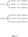
- Wi-Fi signals obtained based on the target object include Wi-Fi signal A, Wi-Fi signal B, Wi-Fi signal C, Wi-Fi signal D, and Wi-Fi signal E
- user equipment a can detect Wi-Fi signal A, Wi-Fi signal B, and Wi-Fi signal C
- user equipment b can detect Wi-Fi signal B, Wi-Fi signal C, and Wi-Fi signal D
- user equipment c can detect Wi-Fi signal B, Wi-Fi signal D, and Wi-Fi signal E
- user equipment d can detect Wi-Fi signal B and Wi-Fi signal C.
- Wi-Fi signal A is detected by different user equipments once
- Wi-Fi signal B is detected by different user equipments for four times
- Wi-Fi signal C is detected by different user equipments for three times
- Wi-Fi signal D is detected by different user equipments twice
- Wi-Fi signal E is detected by different user equipments once.
- the previous five Wi-Fi signals can be sorted in a sequence of a quantity of times of detection by different user equipments: Wi-Fi signal B, Wi-Fi signal C, Wi-Fi signal D, and Wi-Fi signal A/Wi-Fi signal E.
- Wi-Fi signal B detected by different user equipments for the largest quantity of times can be selected, or a preset quantity of Wi-Fi signals can be selected in a sequence of a quantity of times of detection by different user equipments.
- the preset quantity can be determined based on an actual situation. For example, when the preset quantity is 2, Wi-Fi signal B and Wi-Fi signal C can be selected; or when the preset quantity is 3, Wi-Fi signal B, Wi-Fi signal C, and Wi-Fi signal D can be selected.
- the plurality of Wi-Fi signals can be screened based on an actual situation, which is not limited here.
- a mapping relationship between identification information of a target object, identification information of the at least one selected Wi-Fi signal, and a signal strength of the at least one selected Wi-Fi signal can be established.
- Wi-Fi signal A, Wi-Fi signal B, Wi-Fi signal C, Wi-Fi signal D, and Wi-Fi signal E are still used as an example. If Wi-Fi signal B is selected, a mapping relationship between identification information of the target object, identification information of Wi-Fi signal B, and a signal strength of Wi-Fi signal B can be established. If Wi-Fi signal B and Wi-Fi signal C are selected, a mapping relationship between identification information of the target object, identification information of Wi-Fi signal B, identification information of Wi-Fi signal C, a signal strength of Wi-Fi signal B, and a signal strength of Wi-Fi signal C can be established.
- a mapping relationship between identification information of the target object, identification information of a Wi-Fi signal that covers the target object, and a signal strength of the Wi-Fi signal can be obtained.
- a mapping relationship between identification information of each target object, identification information of at least one Wi-Fi signal that covers the target object, and a signal strength of the at least one Wi-Fi signal can be obtained by using the previously described method.
- a mapping relationship between identification information of the Wi-Fi signal, identification information of at least one target object covered by the Wi-Fi signal, and a signal strength of the Wi-Fi signal received by the target object can be determined based on the mapping relationship obtained by using the previous method.
- the mapping relationship can be stored in the database after the mapping relationship is obtained.
- the identification information of the target object corresponding to the identification information of the Wi-Fi signal is identified from the database based on the identification information of the Wi-Fi signal detected by the user equipment, the identification information of the Wi-Fi signal can be matched with the identification information of the Wi-Fi signal included in the mapping relationship stored in the database, to obtain the mapping relationship including the identification information of the Wi-Fi signal, and the identification information of the target object that establishes the mapping relationship with the identification information of the Wi-Fi signal is determined based on the obtained mapping relationship.
- the mapping relationship can be the previously described mapping relationship between identification information of a Wi-Fi signal, identification information of at least one target object covered by the Wi-Fi signal, and a signal strength of the Wi-Fi signal received by the target object, or can be the previously described mapping relationship between identification information of each target object, identification information of at least one Wi-Fi signal that covers the target object, and a signal strength of the at least one Wi-Fi signal, which is not limited.
- the identification information of the target object corresponding to the identification information of the Wi-Fi signal detected by the user equipment can be identified.
- Step 103 Push the identified identification information of the target object to the user equipment.
- step 103 when the identification information of the target object corresponding to the identification information of the Wi-Fi signal is identified, the identification information of the target object can be pushed to the user equipment, so that the user of the user equipment can conveniently check the identification information of the target object.
- the identification information of the target object covered by the Wi-Fi signal can be identified based on the identification information of the Wi-Fi signal, and the identification information of the target object can be pushed to the user equipment when the identification information of the target object is identified.
- one or more Wi-Fi signals may be detected by the user equipment.
- one or more target objects corresponding to the identification information of the Wi-Fi signal may be identified. Therefore, when the identification information of the target object is pushed to the user equipment, if one target object is identified, the identification information of the target object can be recommended to the user equipment; or if a plurality of target objects are identified, identification information of the plurality of target objects can be pushed to the user equipment, or the plurality of target objects can be screened, and identification information of at least one selected target object is pushed to the user equipment.
- searching the database for the identification information of the target object based on the identification information of the detected Wi-Fi signal includes at least the following situations:
- the identification information of the target object can be pushed to the user equipment.
- At least one target object can be selected, and identification information of the selected target object is pushed to the user of the user equipment.
- the pushing the identified identification information of the target object to the user equipment includes the following: when it is determined that a quantity of identified target objects is greater than 1, determining a first signal strength of the Wi-Fi signal detected by the user equipment; searching the database for a second signal strength of the Wi-Fi signal that has the mapping relationship with the identification information of the target object, where the database includes a mapping relationship between identification information of a target object, identification information of a Wi-Fi signal that covers the target object, and a signal strength of the Wi-Fi signal; and selecting at least one target object based on the first signal strength of the Wi-Fi signal and the second signal strength of the Wi-Fi signal, and pushing identification information of the selected target object to the user equipment.
- the signal strength of the Wi-Fi signal detected by the user equipment can be determined.
- the signal strength of the Wi-Fi signal can be determined based on the feature information of the detected Wi-Fi signal.
- the signal strength of the Wi-Fi signal corresponding to identification information of each target object can be identified from the previously described database based on identification information of the plurality of identified target objects.
- the signal strength of the Wi-Fi signal detected by the user equipment can be referred to as the first signal strength of the Wi-Fi signal, and the signal strength of the Wi-Fi signal identified from the database is referred to as the second signal strength of the Wi-Fi signal.
- the at least one target object can be selected based on the first signal strength of the Wi-Fi signal and the second signal strength of the Wi-Fi signal.
- the selecting at least one target object based on the first signal strength of the Wi-Fi signal and the second signal strength of the Wi-Fi signal includes: calculating an eigenvalue of the target object based on the first signal strength of the Wi-Fi signal and the second signal strength of the Wi-Fi signal, where the eigenvalue is used to represent a location relationship between the user equipment and the target object; and selecting the at least one target object based on the eigenvalue of the target object.
- the eigenvalue of the target object can be calculated, and the eigenvalue here can be used to represent the location relationship between the target object and the user equipment.
- a and b can be used to limit a value range of the eigenvalue of the target object, and can be determined based on an actual situation.
- a can be 1
- b can be 1.
- the eigenvalue of each target object can be obtained by using the previously described equation.
- the eigenvalue of each target object can alternatively be obtained by using another method, which is not limited here.
- an absolute value of a difference between the first signal strength of the Wi-Fi signal and the second signal strength of the Wi-Fi signal received by the target object can be calculated, and the calculated absolute value of the difference is used as the eigenvalue of the target object.
- the at least one target object can be selected based on the eigenvalue.
- the at least one target object can be sorted in ascending order of eigenvalues or in descending order of eigenvalues, which is not limited here.
- At least one target object can be selected based on a sorting result.
- the smaller difference between the first signal strength of the Wi-Fi signal and the second signal strength of the Wi-Fi signal received by the target object indicates the larger eigenvalue of the target object.
- a smaller difference between the first signal strength of the Wi-Fi signal and the second signal strength of the Wi-Fi signal indicates a shorter distance between the user equipment and the target object. Therefore, when the at least one target object is selected based on the sorting result, at least one target object having an eigenvalue greater than a preset threshold can be selected in descending order of eigenvalues of the target objects, and the preset threshold here can be determined based on an actual situation.
- a smaller difference between the first signal strength of the Wi-Fi signal and the second signal strength of the Wi-Fi signal received by the target object indicates a smaller eigenvalue of the target object, and indicates a shorter distance between the user equipment and the target object in practice.
- at least one target object having an eigenvalue less than a preset threshold can be selected when the at least one target object is selected based on a sorting result, and the preset threshold here can be determined based on an actual situation.
- the at least one target object can alternatively be selected based on an actual situation, which is not limited here.
- the identification information of the target object can be pushed to the user equipment.
- At least one target object can be selected, and identification information of the selected target object is pushed to the user equipment.
- the first signal strength of each Wi-Fi signal detected by the user equipment can be determined by using the method described in situation 2, and the second signal strength of the Wi-Fi signal received by each target object is identified. Details are omitted here for simplicity.
- an eigenvalue of each target object can be calculated.
- the eigenvalue of each target object can be calculated by using at least the following several methods.
- a and b can be used to limit a value range of the eigenvalue of the target object, and can be determined based on an actual situation.
- a can be 1
- b can be 1.
- Wi-Fi signals here are Wi-Fi signals detected by the user equipment
- Wi-Fi signals received by the target object indicates a shorter distance between the target object and the user equipment.
- Wi-Fi signal received by the target object it can be seen from the equation that the smaller difference between the first signal strength of the Wi-Fi signal detected by the user equipment and the second signal strength of the Wi-Fi signal received by the target object, and the shorter distance between the user equipment and the target object indicate a larger eigenvalue of the target object.
- the eigenvalue of the target object is calculated, if a plurality of Wi-Fi signals can be received by the target object, eigenvalues of target objects corresponding to the Wi-Fi signals can be added. As such, a larger eigenvalue of the target object indicates a shorter distance between the target object and the user equipment.
- Wi-Fi signal A and Wi-Fi signal B two Wi-Fi signals are detected by the user equipment: Wi-Fi signal A and Wi-Fi signal B, a signal strength of detected Wi-Fi signal A is s A , and a signal strength of detected Wi-Fi signal B is s B .
- Target objects that are covered by Wi-Fi signal A and that can be identified from the database based on identification information of Wi-Fi signal A are target object 1, target object 2, and target object 3.
- a signal strength of Wi-Fi signal A received by target object 1 identified from the database is s A1
- a signal strength of Wi-Fi signal A received by target object 2 is s A2
- a signal strength of Wi-Fi signal A received by target object 3 is s A3 .
- Target objects that are covered by Wi-Fi signal B and that can be identified from the database based on identification information of Wi-Fi signal B are target object 2, target object 3, and target object 4.
- a signal strength of Wi-Fi signal B received by target object 2 identified from the database is s B2
- a signal strength of Wi-Fi signal B received by target object 3 is s B3
- a signal strength of Wi-Fi signal B received by target object 4 is s B4 .
- Eigenvalues of target object 1, target object 2, target object 3, and target object 4 can be separately calculated based on the previously described equation, where preset parameter a is 1, and preset parameter b is 1.
- Wi-Fi signals here are Wi-Fi signals detected by the user equipment
- the eigenvalue of the target object can be determined based on a quantity of Wi-Fi signals that can be received by the target object. It can be seen from the equation that a larger quantity of Wi-Fi signals received by the target object indicates a larger eigenvalue of the target object.
- Wi-Fi signals detected by the user equipment are Wi-Fi signal A and Wi-Fi signal B. It can be determined that target object 1 can receive one Wi-Fi signal, target object 2 can receive two Wi-Fi signals, target object 3 can receive two Wi-Fi signals, and target object 4 can receive one Wi-Fi signal. In this situation, it can be determined that an eigenvalue of target object 1 is 1, an eigenvalue of target object 2 is 2, an eigenvalue of target object 3 is 2, and an eigenvalue of target object 4 is 1.
- the eigenvalue of each target object can alternatively be calculated by using another method, which is not limited here.
- the at least one target object can be selected based on the eigenvalue.
- the at least one target object can be sorted in ascending order of eigenvalues or in descending order of eigenvalues, which is not limited here.
- At least one target object can be selected based on a sorting result.
- a smaller difference between the first signal strength of the Wi-Fi signal and the second signal strength of the Wi-Fi signal received by the target object indicates a larger quantity of Wi-Fi signals received by the target object and a larger eigenvalue of the target object.
- a smaller difference between the first signal strength of the Wi-Fi signal and the second signal strength of the Wi-Fi signal received by the target object and a larger quantity of Wi-Fi signals received by the target object indicates a shorter distance between the user equipment and the target object.
- At least one target object having an eigenvalue greater than a preset threshold can be selected in descending order of eigenvalues of the target objects, and the preset threshold here can be determined based on an actual situation.
- a larger quantity of Wi-Fi signals received by the target object indicates a larger eigenvalue of the target object.
- a larger quantity of Wi-Fi signals received by the target object indicates a shorter distance between the user equipment and the target object. Therefore, when the at least one target object is selected based on the sorting result, at least one target object having an eigenvalue greater than a preset threshold can be selected in descending order of eigenvalues of the target objects, and the preset threshold here can be determined based on an actual situation.
- the at least one target object can alternatively be selected based on an actual situation, which is not limited here.
- the method further includes: determining, based on the eigenvalue of the target object, whether a location of the user equipment is consistent with a location of the selected target object.
- a smaller difference between the first signal strength of the Wi-Fi signal and the second signal strength of the Wi-Fi signal indicates a larger quantity of Wi-Fi signals received by the target object and a larger eigenvalue of the target object.
- a smaller difference between the first signal strength and the second signal strength and a larger quantity of Wi-Fi signals received by the target object indicates a shorter distance between the user equipment and the target object. Therefore, after the eigenvalue of the target object is obtained, whether a location of the user equipment is consistent with a location of the selected target object can be determined based on the eigenvalue.
- the preset value here can be determined based on an actual situation, and is not limited.
- the identification information of the target object can be pushed to the user equipment after the identification information of the target object is determined, so that the user of the user equipment can obtain the identification information of the target object.
- the pushing the identification information of the target object to the user equipment includes: determining push information about the target object, and pushing the push information to the user equipment.
- the push information about the target object and the identification information of the target object can be jointly pushed to the user equipment.
- the push information about the target object can be information about the target object.
- the push information can be information about merchandise in the shop (for example, price or sales information of the merchandise), or can be other information about the shop, which is not limited here.
- the user of the user equipment can obtain more information about the target object.
- the user can send a service request related to the target object to the server based on the obtained push information.
- the server can receive the service request sent by the user.
- the method further includes: receiving a service request sent by a user, where the service request includes the identification information of the target object and the feature information of the Wi-Fi signal, and the feature information includes the identification information of the Wi-Fi signal and a signal strength of the Wi-Fi signal; and updating, based on the feature information of the Wi-Fi signal included in the service request, feature information of the Wi-Fi signal that is stored in the database and that covers the target object.
- the server can receive the service request.
- the service request can include the identification information of the target object and the feature information of the Wi-Fi signal.
- the feature information can include the identification information of the Wi-Fi signal and the signal strength of the Wi-Fi signal.
- the Wi-Fi signal can be a Wi-Fi signal to which the user equipment is connected or at least one Wi-Fi signal detected by the user equipment when the user sends the service request, which is not limited.
- the feature information of the Wi-Fi signal that is stored in the database and that corresponds to the identification information of the target object can be updated based on the obtained feature information of the Wi-Fi signal.
- the feature information of the Wi-Fi signal can be updated based on the obtained feature information of the Wi-Fi signal.
- the identification information of the target object covered by the Wi-Fi signal is determined based on the feature information of the Wi-Fi signal that can be currently detected by the user equipment, and the determined identification information of the target object is pushed to the user equipment, so that the user of the user equipment can quickly obtain the identification information of the target object.
- coverage of the Wi-Fi signal is relatively small, the accuracy of the target object determined based on the Wi-Fi signal is relatively high, so that information about the target object displayed to the user can satisfy an actual demand of the user, thereby effectively improving user experience.
- a shop is used as an example of a target object below to describe how to determine, by using the technical solution provided in this implementation of the present application, a shop relatively close to a user, and push identification information of the shop to the user.
- a mapping relationship between the identification information of the shop, identification information of a Wi-Fi signal that covers the shop, and a signal strength of the Wi-Fi signal that covers the shop is determined.
- the identification information of the shop here can be the name of the shop.
- a server can obtain feature information of the Wi-Fi signal to which the user equipment is connected when the user sends the service request, or can obtain feature information of a Wi-Fi signal detected by the user equipment within a preset period before and after the user sends the service request.
- the preset period here can be any period of time when the user is in the shop.
- the preset period can be one minute, and the feature information of the Wi-Fi signal detected by the user equipment within one minute before and after a user transaction moment is obtained.
- feature information of Wi-Fi signals to which the user equipment is connected (or feature information of Wi-Fi signals detected by the user equipment) when the user in the shop sends the service request related to the shop within one month (or two months; the period is not limited) can be accumulated. After a large amount of feature information of the Wi-Fi signals is obtained, the accumulated feature information of the Wi-Fi signals can be analyzed and processed.
- a Wi-Fi signal with abnormal identification information can be excluded, and a Wi-Fi signal with a signal strength that ranges from 0 dB to -120 dB is selected.
- a preset quantity of Wi-Fi signals detected by different user equipments for a relatively large quantity of times can be selected based on a quantity of times that the Wi-Fi signal is detected by different user equipments. For example, if there are 20 Wi-Fi signals, Wi-Fi signals detected by different user equipments for the first ten largest quantities of times can be selected.
- an average value of the signal strengths of the Wi-Fi signals can be calculated, and the average value is used as the signal strength of the Wi-Fi signal.
- mapping relationship between the identification information of the shop, identification information of a Wi-Fi signal that covers the shop, and a signal strength of the Wi-Fi signal that covers the shop can be established.
- a mapping relationship between identification information of each shop, identification information of a Wi-Fi signal that covers the shop, and a signal strength of the Wi-Fi signal that covers the shop can be obtained by using the described method.
- a mapping relationship between identification information of each shop, identification information of a Wi-Fi signal that covers the shop, and a signal strength of the Wi-Fi signal that covers the shop can be obtained. Further, for one Wi-Fi signal, a mapping relationship between identification information of the Wi-Fi signal, identification information of a shop covered by the Wi-Fi signal, and a signal strength of the Wi-Fi signal received by the shop can be obtained.
- the mapping relationship can be stored in the database after the mapping relationship is obtained.
- information about the shop is pushed to the user based on the feature information of the Wi-Fi signal currently detected by the user equipment.
- the identification information of the shop corresponding to the identification information of the Wi-Fi signal can be identified from the database based on the identification information of the Wi-Fi signal detected by the user equipment.
- push information about the shop can be pushed to the user equipment. If a plurality of shops are identified, eigenvalues of the shops can be calculated, at least one shop is selected based on the calculated eigenvalues, and push information about the selected shop is pushed to the user equipment, so that the user of the user equipment can obtain information about the shop based on the pushed information.
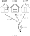
- Wi-Fi signals that can be detected by the user equipment are Wi-Fi 1 and Wi-Fi 3, a signal strength of Wi-Fi 1 detected by the user equipment is -70 dB, and a signal strength of Wi-Fi 3 is -60 dB.
- shops correspond to Wi-Fi 1 are shop 1, shop 2, and shop 3, a signal strength of Wi-Fi 1 received in shop 1 is -30 dB, a signal strength of Wi-Fi 1 received in shop 2 is -60 dB, and a signal strength of Wi-Fi 1 received in shop 3 is -100 dB.
- shops correspond to Wi-Fi 3 are shop 1, shop 2, and shop 3, a signal strength of Wi-Fi 3 received in shop 1 is -100 dB, a signal strength of Wi-Fi 3 received in shop 2 is -60 dB, and a signal strength of Wi-Fi 3 received in shop 3 is -20 dB.
- shop 1 and shop 3 are also covered by Wi-Fi 1 and Wi-Fi 3, push information about shop 1 and push information about shop 3 can also be pushed to the user equipment, and push information of three shops can be displayed to the user in this sequence: shop 2, shop 3, and shop 1.
- the eigenvalue of shop 2 is the largest, it can be determined that a current location of the user is consistent with a location of shop 2; in other words, the user is in shop 2.
- the user equipment can display information about shop 2, for example, price information and sales information of all commodities in shop 2. Therefore, the user of the user equipment can quickly obtain the information about shop 2.
- the user can consume merchandise in shop 2.
- the user can send a service request including identification information of shop 2, and the service request can include feature information of a Wi-Fi signal to which the user equipment is connected.
- the previously described mapping relationship between the identification information of the shop, identification information of a Wi-Fi signal that covers the shop, and a signal strength of the Wi-Fi signal that covers the shop can be updated based on the feature information of the Wi-Fi signal and the identification information of shop 2.
- feature information of a Wi-Fi signal detected by the user equipment each day can be obtained, and identification information and time information of a shop usually passed by the user are determined based on the obtained feature information of the Wi-Fi signal.
- information about the shop can be displayed to the user in a specific time period. For example, if the user passes shop 1 at 8:00 a.m. to 9:00 a.m. every day, information about shop 1 can be pushed to the user before 8: 00 every day, so that the user can consume merchandise based on the pushed information when passing shop 1 between 8:00 a.m. and 9:00 a.m.
- FIG. 4 is a schematic flowchart illustrating a location positioning method, according to an implementation of the present application. The method includes the following steps.
- Step 401 Obtain feature information of a Wi-Fi signal detected by user equipment.
- the feature information includes identification information of the Wi-Fi signal.
- a user can detect, by using current user equipment, at least one Wi-Fi signal that covers the user equipment.
- the feature information of the Wi-Fi signal can be obtained based on the Wi-Fi signal detected by the user equipment.
- the feature information of the Wi-Fi signal can include the identification information of the Wi-Fi signal and a signal strength of the Wi-Fi signal.
- a method for obtaining a Wi-Fi signal detected by the user equipment is the same as the method described in step 101. Details are omitted here for simplicity.
- Step 402 Search a database for identification information of a target object corresponding to identification information of the Wi-Fi signal.
- the database includes a mapping relationship between identification information of a Wi-Fi signal and identification information of a target object covered by the Wi-Fi signal.
- step 402 after the identification information of the Wi-Fi signal detected by the user equipment is obtained, the target object corresponding to the identification information of the Wi-Fi signal can be identified from the database based on the identification information of the Wi-Fi signal, so as to determine a location of the user equipment based on a location of the target object.
- the mapping relationship between identification information of a Wi-Fi signal and identification information of a target object covered by the Wi-Fi signal can be pre-stored in the database.
- the identification information of the Wi-Fi signal is obtained, the identification information of the target object corresponding to the identification information of the Wi-Fi signal can be identified from the database based on the identification information of the Wi-Fi signal.
- the database can be determined by using the following method, including the following steps.
- Step 1 Obtain feature information of the Wi-Fi signal that covers the target object, where the feature information of the Wi-Fi signal is included in a service request sent by a user, the feature information of the Wi-Fi signal includes the identification information of the Wi-Fi signal and the signal strength of the Wi-Fi signal, and the service request includes the identification information of the target object.
- the feature information of the Wi-Fi signal that covers the target object can be obtained by using the method described in step 102. Details are omitted here for simplicity.
- Step 2 Establish a mapping relationship between identification information of a target object, identification information of a Wi-Fi signal that covers the target object, and a signal strength of the Wi-Fi signal, and store the mapping relationship in the database.
- the mapping relationship between identification information of a target object, identification information of a Wi-Fi signal that covers the target object, and a signal strength of the Wi-Fi signal can be established by using the method described in step 102. Details are omitted here for simplicity.
- a mapping relationship between identification information of a Wi-Fi signal, identification information of at least one target object covered by the Wi-Fi signal, and a signal strength of the Wi-Fi signal received by the target object can be further established by using the method described in step 102.
- the mapping relationship can be stored in the database after the mapping relationship is obtained.
- the identification information of the target object corresponding to the identification information of the Wi-Fi signal can be identified from the database by using the method described in step 102. Details are omitted here for simplicity.
- Step 403 Determine an eigenvalue of the target object corresponding to the identification information.
- the eigenvalue is used to represent a location relationship between the user equipment and the target object.
- the eigenvalue of the target object corresponding to the identification information can be further determined, so as to determine, based on the eigenvalue of the target object, whether a location of the user equipment is consistent with a location of the target object.
- the eigenvalue of the target object can be used to represent the location relationship between the user equipment and the target object.
- the determining an eigenvalue of the target object corresponding to the identification information includes: determining a first signal strength of the Wi-Fi signal detected by the user equipment; searching the database for a second signal strength of the Wi-Fi signal that has the mapping relationship with the identification information of the target object, where the database includes a mapping relationship between identification information of a target object, identification information of a Wi-Fi signal that covers the target object, and a signal strength of the Wi-Fi signal; and determining the eigenvalue of the target object based on the first signal strength of the Wi-Fi signal and the second signal strength of the Wi-Fi signal.
- the first signal strength of the Wi-Fi signal detected by the user equipment can be determined by using the method described in step 103, and the second signal strength of the Wi-Fi signal that has the mapping relationship with the identification information of the target object is identified from the database by using the method described in step 103. Details are omitted here for simplicity.
- the eigenvalue of the target object can be calculated by using the method described in step 103. Details are omitted here for simplicity.
- Step 404 Determine, based on the eigenvalue of the target object, whether a location of the user equipment is consistent with a location of the target object.
- step 404 after the eigenvalue of the target object is calculated, whether the location of the user equipment is consistent with the location of the target object can be determined based on the eigenvalue of the target object.
- one or more Wi-Fi signals may be detected by the user equipment, and one or more target objects may be identified from the database. Therefore, when one target object is identified, it indicates that the user equipment and the target object can receive the Wi-Fi signal, and in this situation, it can be determined that the location of the user equipment is consistent with the location of the target object; or when a plurality of target objects are identified, the plurality of target objects can be screened, and the location of the user equipment is determined based on a location of the selected target object.
- searching the database for the identification information of the target object based on the identification information of the detected Wi-Fi signal includes at least the following situations:
- Wi-Fi signal There is one Wi-Fi signal, and one target object is identified. In practice, it indicates that the user equipment and the target object can receive the Wi-Fi signal. In this situation, it can be determined that the location of the user equipment is consistent with the location of the target object.
- the location of the user equipment is consistent with the location of the target object is determined based on an eigenvalue of each target object, it can be determined whether the eigenvalue of each target object is greater than a preset value. If yes, it indicates that the user equipment is relatively close to the target object. Therefore, it can be determined that the location of the user equipment is consistent with the location of the target object.
- the preset value can be determined based on an actual situation, and is not limited here.
- Wi-Fi signals There are a plurality of Wi-Fi signals, and one target object is identified. In practice, it indicates that the user equipment and the target object can receive the plurality of Wi-Fi signals. In this situation, it can be determined that the location of the user equipment is consistent with the location of the target object.
- whether the location of the user equipment is consistent with the location of the target object can be determined based on the described four situations and the eigenvalue of the target object.
- the identification information of the target object covered by the Wi-Fi signal is identified based on the feature information of the Wi-Fi signal detected by the user equipment, and the eigenvalue of the target object is determined, so as to determine the location of the user equipment based on the eigenvalue of the target object. Because coverage of the Wi-Fi signal is relatively small, the accuracy of the user equipment's location determined based on the Wi-Fi signal is relatively high.
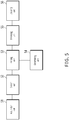
- FIG. 5 is a schematic structural diagram illustrating an information pushing device, according to an implementation of the present application.
- the information pushing device includes an acquisition unit 51, a search unit 52, and a pushing unit 53.
- the acquisition unit 51 obtains feature information of a Wi-Fi signal detected by user equipment, where the feature information includes identification information of the Wi-Fi signal.
- the search unit 52 searches a database for identification information of a target object corresponding to the identification information of the Wi-Fi signal, where the database includes a mapping relationship between identification information of a Wi-Fi signal and identification information of a target object covered by the Wi-Fi signal.
- the pushing unit 53 pushes the identification information of the target object identified by the search unit 52 to the user equipment.
- the pushing unit 53 pushes the identification information of the target object identified by the search unit 52 to the user equipment, including: when it is determined that a quantity of identified target objects is greater than 1, determining a first signal strength of the Wi-Fi signal detected by the user equipment; searching the database for a second signal strength of the Wi-Fi signal that has the mapping relationship with the identification information of the target object, where the database includes a mapping relationship between identification information of a target object, identification information of a Wi-Fi signal that covers the target object, and a signal strength of the Wi-Fi signal; and selecting at least one target object based on the first signal strength of the Wi-Fi signal and the second signal strength of the Wi-Fi signal, and pushing identification information of the selected target object to the user equipment.
- the pushing unit 53 selects at least one target object based on the first signal strength of the Wi-Fi signal and the second signal strength of the Wi-Fi signal, including: calculating an eigenvalue of the target object based on the first signal strength of the Wi-Fi signal and the second signal strength of the Wi-Fi signal, where the eigenvalue is used to represent a location relationship between the user equipment and the target object; and selecting the at least one target object based on the eigenvalue of the target object.
- the information pushing device further includes a determining unit 54.
- the determining unit 54 determines, based on the eigenvalue of the target object, whether a location of the user equipment is consistent with a location of the target object.
- the search unit 52 determines the database by using the following method, including: obtaining feature information of the Wi-Fi signal that covers the target object, where the feature information of the Wi-Fi signal is included in a service request sent by a user, the feature information of the Wi-Fi signal includes the identification information of the Wi-Fi signal and the signal strength of the Wi-Fi signal, and the service request includes the identification information of the target object; and establishing the mapping relationship between identification information of a target object, identification information of a Wi-Fi signal that covers the target object, and a signal strength of the Wi-Fi signal, and storing the mapping relationship in the database.
- the pushing unit 53 pushes the identification information of the target object identified by the search unit 52 to the user equipment, including: determining push information about the target object, and pushing the push information to the user equipment.
- the information pushing device further includes a receiving unit 55 and an updating unit 56.
- the receiving unit 55 receives a service request sent by a user, where the service request includes the identification information of the target object and the feature information of the Wi-Fi signal, and the feature information includes the identification information of the Wi-Fi signal and a signal strength of the Wi-Fi signal.
- the updating unit 56 updates, based on the feature information of the Wi-Fi signal included in the service request, feature information of the Wi-Fi signal that is stored in the database and that covers the target object.
- the acquisition unit obtains the feature information of the Wi-Fi signal that can be detected by the user equipment, the search unit searches for the identification information of the target object covered by the Wi-Fi signal, and the pushing unit pushes the identification information of the target object identified by the search unit to the user equipment, so that a user of the user equipment can quickly obtain the identification information of the target object.
- coverage of the Wi-Fi signal is relatively small, the accuracy of the target object determined based on the Wi-Fi signal is relatively high, so that information about the target object displayed to the user can satisfy an actual demand of the user, thereby effectively improving user experience.
- FIG. 6 is a schematic structural diagram illustrating a location positioning device, according to an implementation of the present application.
- the location positioning device includes an acquisition unit 61, a search unit 62, a determining unit 63, and a location determining unit 64.
- the acquisition unit 61 obtains feature information of a Wi-Fi signal detected by user equipment, where the feature information includes identification information of the Wi-Fi signal.
- the search unit 62 searches a database for identification information of a target object corresponding to the identification information of the Wi-Fi signal, where the database includes a mapping relationship between identification information of a Wi-Fi signal and identification information of a target object covered by the Wi-Fi signal.
- the determining unit 63 determines an eigenvalue of the target object corresponding to the identification information, where the eigenvalue is used to represent a location relationship between the user equipment and the target object.
- the location determining unit 64 determines, based on the eigenvalue of the target object, whether a location of the user equipment is consistent with a location of the target object.
- the determining unit 63 determines an eigenvalue of the target object corresponding to the identification information, including: determining a first signal strength of the Wi-Fi signal detected by the user equipment; searching the database for a second signal strength of the Wi-Fi signal that has the mapping relationship with the identification information of the target object, where the database includes a mapping relationship between identification information of a target object, identification information of a Wi-Fi signal that covers the target object, and a signal strength of the Wi-Fi signal; and determining the eigenvalue of the target object based on the first signal strength of the Wi-Fi signal and the second signal strength of the Wi-Fi signal.
- the search unit 62 determines the database by using the following method, including: obtaining feature information of the Wi-Fi signal that covers the target object, where the feature information of the Wi-Fi signal is included in a service request sent by a user, the feature information of the Wi-Fi signal includes the identification information of the Wi-Fi signal and the signal strength of the Wi-Fi signal, and the service request includes the identification information of the target object; and establishing the mapping relationship between identification information of a target object, identification information of a Wi-Fi signal that covers the target object, and a signal strength of the Wi-Fi signal, and storing the mapping relationship in the database.
- positioning device provided in this implementation of the present application can be implemented by using hardware or software, which is not limited here.
- the acquisition unit obtains the feature information of the Wi-Fi signal that can be detected by the user equipment, the search unit searches for the identification information of the target object covered by the Wi-Fi signal, and the determining unit determines the eigenvalue of the target object and determines the location of the user equipment based on the eigenvalue of the target object. Because coverage of the Wi-Fi signal is relatively small, the accuracy of the user equipment's location determined based on the Wi-Fi signal is relatively high.
- the implementations of the present application can be provided as a method, a system, or a computer program product. Therefore, the present application can use a form of hardware only implementations, software only implementations, or implementations with a combination of software and hardware. In addition, the present application can use a form of a computer program product that is implemented on one or more computer-usable storage media (including but not limited to a disk memory, a CD-ROM, an optical memory, etc.) that include computer-usable program code.
- computer-usable storage media including but not limited to a disk memory, a CD-ROM, an optical memory, etc.
- These computer program instructions can be provided for a general-purpose computer, a dedicated computer, an embedded processor, or a processor of any other programmable data processing device to generate a machine, so that the instructions executed by a computer or a processor of any other programmable data processing device generate an apparatus for implementing a specific function in one or more processes in the flowcharts and/or in one or more blocks in the block diagrams.
- These computer program instructions can be stored in a computer readable memory that can instruct the computer or any other programmable data processing device to work in a specific way, so that the instructions stored in the computer readable memory generate an artifact that includes an instruction apparatus.
- the instruction apparatus implements a specific function in one or more processes in the flowcharts and/or in one or more blocks in the block diagrams.
- the computing device includes one or more processors (CPUs), an input/output interface, a network interface, and a memory.
- the memory can include a form of a volatile memory, a random access memory (RAM) and/or a non-volatile memory, etc., in a computer readable medium, such as a read-only memory (ROM) or a flash memory (flash RAM).
- ROM read-only memory
- flash RAM flash memory
- the computer readable medium includes volatile and non-volatile, removable and non-removable media, and can store information by using any method or technology.
- the information can be a computer readable instruction, a data structure, a program module, or other data.
- the examples of computer storage medium include but are not limited to a phase-change random access memory (PRAM), a static random access memory (SRAM), a dynamic random access memory (DRAM), a random access memory (RAM) of another type, a read-only memory (ROM), an electrically erasable programmable read-only memory (EEPROM), a flash memory or another memory technology, a compact disc read-only memory (CD-ROM), a digital versatile disc (DVD) or another optical storage, a magnetic tape, a magnetic disk storage, another magnetic storage device, or any other non-transmission medium.
- the computer storage medium can be used to store information that can be accessed by the computing device. As described in this specification, the computer readable medium does not include transitory media (transitory media), for
- the implementations of the present application can be provided as a method, a system, or a computer program product. Therefore, the present application can use a form of hardware only implementations, software only implementations, or implementations with a combination of software and hardware. In addition, the present application can use a form of a computer program product that is implemented on one or more computer-usable storage media (including but not limited to a disk memory, a CD-ROM, an optical memory, etc.) that include computer-usable program code.
- computer-usable storage media including but not limited to a disk memory, a CD-ROM, an optical memory, etc.
Description
- The present application claims priority to
Chinese Patent Application No. 201610438833.5, filed on June 17, 2016 - The present application relates to the field of Internet information technologies, and in particular, to an information pushing method and a location positioning method and device.
- With the rapid development of information technologies and Internet technologies, a growing number of people obtain related information by using the Internet. Generally, when obtaining the related information by using the Internet, the user can enter a target object to be searched on an Internet platform, and the Internet platform can search based on the target object entered by the user, and display information about the identified target object to the user. Therefore, the user can conveniently obtain the information about the target object.
- To help the user to better obtain the information about the target object, when the Internet platform is to display the information about the target object to the user, the Internet platform can display, to the user based on current geographical location information of the user, information about a target object relatively close to the user. Firstly, the user's current geographical location information can be determined through positioning; secondly, the target object relatively close to the user is determined based on the user's current geographical location information; and finally, the information about the determined target object relatively close to the user is displayed to the user. Therefore, the user can conveniently obtain the information about the target object relatively close to the user.
- Generally, when determining the target object relatively close to the user, the Internet platform can match user's geographical location information with address information of the target object, and determine the target object based on a matching result. However, the accuracy of the determined target object is relatively low as the matching accuracy is relatively low. Consequently, the information about the target object displayed to the user usually cannot satisfy an actual demand of the user, causing relatively poor user experience.
-
US 8 233 913 B2 describes systems and methods for obtaining a signature for a place. A server receives information about a place, such as name of the place, from client devices when the devices are at the place, and data related to wireless transmission stations detected by the client devices. The data comprises wireless transmission station identifiers and signal strength information. The server associates the information about the place with the data. Also described are systems and methods for detecting a place for a client device. The server receives data related to one or more wireless transmission stations detected by the client device when the device is at the place. The data comprises wireless transmission station identifiers and signal strength information. The server compares the set of data with signatures of places, selects a signature based on the comparison, and transmits to the client device information about the place in the selected signature. -
US 8 385 943 B1 describes a method and apparatus for determining location information of a position in a multi-storey building. The method comprises: retrieving observation data comprising observed addresses and corresponding observed received signal strengths of wireless access points detected at the position from a memory; retrieving, for each storey of the building, a radio map comprising a plurality of location points in the respective storey of the building from a database, each location point comprising addresses and corresponding mean received signal strengths of wireless access points detected at the location point and coordinates of the location point; selecting one or more location points comprising the observed addresses from the radio map; determining a storey estimate of the position by calculating a sum probability for each storey of the building, the sum probability being calculated by summing all individual probabilities of each observed address contained in each selected location point in the radio map of the respective storey being detected on the respective storey; and setting the storey estimate as the storey of the building having highest value of the calculated sum probability, wherein each of said individual probabilities is calculated based on the corresponding observed received signal strength of said each observed address in said each selected location point and the corresponding mean received signal strength in said each selected location point containing said each observed address. - Implementations of the present application provide an information pushing method and a location positioning method and device, so as to alleviate an existing problem that user experience is relatively poor because information about a target object displayed to a user cannot satisfy an actual demand of the user.
- An implementation of the present application provides an information pushing method, including the following: obtaining feature information of a Wi-Fi signal detected by user equipment, where the feature information includes identification information of the Wi-Fi signal; searching a database for identification information of a target object corresponding to the identification information of the Wi-Fi signal, where the database includes a mapping relationship between identification information of a Wi-Fi signal and identification information of a target object covered by the Wi-Fi signal; and pushing the identified identification information of the target object to the user equipment.
- An implementation of the present application provides an information pushing device, including the following: an acquisition unit, configured to obtain feature information of a Wi-Fi signal detected by user equipment, where the feature information includes identification information of the Wi-Fi signal; a search unit, configured to search a database for identification information of a target object corresponding to the identification information of the Wi-Fi signal, where the database includes a mapping relationship between identification information of a Wi-Fi signal and identification information of a target object covered by the Wi-Fi signal; and a pushing unit, configured to push the identification information of the target object identified by the search unit to the user equipment.
- At least one of the previously described technical solutions adopted in the implementations of the present application can achieve the following beneficial effects:
- In the technical solutions provided in the implementations of the present application, the identification information of the target object covered by the Wi-Fi signal is determined based on the feature information of the Wi-Fi signal that can be currently detected by the user equipment, and the determined identification information of the target object is pushed to the user equipment, so that the user of the user equipment can quickly obtain the identification information of the target object. In addition, because coverage of the Wi-Fi signal is relatively small, the accuracy of the target object determined based on the Wi-Fi signal is relatively high, and information about the target object displayed to the user can satisfy an actual demand of the user, thereby effectively improving user experience.
- An implementation of the present application provides a location positioning method, including the following: obtaining feature information of a Wi-Fi signal detected by user equipment, where the feature information includes identification information of the Wi-Fi signal; searching a database for identification information of a target object corresponding to the identification information of the Wi-Fi signal, where the database includes a mapping relationship between identification information of a Wi-Fi signal and identification information of a target object covered by the Wi-Fi signal; determining an eigenvalue of the target object corresponding to the identification information, where the eigenvalue is used to represent a location relationship between the user equipment and the target object; and determining, based on the eigenvalue of the target object, whether a location of the user equipment is consistent with a location of the target object.
- An implementation of the present application provides a location positioning device, including the following: an acquisition unit, configured to obtain feature information of a Wi-Fi signal detected by user equipment, where the feature information includes identification information of the Wi-Fi signal; a search unit, configured to search a database for identification information of a target object corresponding to the identification information of the Wi-Fi signal, where the database includes a mapping relationship between identification information of a Wi-Fi signal and identification information of a target object covered by the Wi-Fi signal; a determining unit, configured to determine an eigenvalue of the target object corresponding to the identification information, where the eigenvalue is used to represent a location relationship between the user equipment and the target object; and a location determining unit, configured to determine, based on the eigenvalue of the target object, whether a location of the user equipment is consistent with a location of the target object.
- In the technical solutions provided in the implementations of the present application, the identification information of the target object covered by the Wi-Fi signal is identified based on the feature information of the Wi-Fi signal detected by the user equipment, and the eigenvalue of the target object is determined, so as to determine the location of the user equipment based on the eigenvalue of the target object. Because coverage of the Wi-Fi signal is relatively small, the accuracy of the user equipment's location based on the Wi-Fi signal is relatively high.
- The accompanying drawings described here are intended to provide a further understanding of the present application, and constitute a part of the present application. The illustrative implementations of the present application and descriptions thereof are intended to describe the present application, and do not constitute limitations on the present application. In the accompanying drawings:
-
FIG. 1 is a schematic flowchart illustrating an information pushing method, according to an implementation of the present application; -
FIG. 2 is a schematic diagram illustrating a mapping relationship between identification information of a Wi-Fi signal, a target object covered by the Wi-Fi signal, and a signal strength of the Wi-Fi signal, according to an implementation of the present application; -
FIG. 3 is a schematic diagram illustrating determining eigenvalue of a shop, according to an implementation of the present application; -
FIG. 4 is a schematic flowchart illustrating a location positioning method, according to an implementation of the present application; -
FIG. 5 is a schematic structural diagram illustrating an information pushing device, according to an implementation of the present application; and -
FIG. 6 is a schematic structural diagram illustrating a location positioning device, according to an implementation of the present application. - In the existing technology, when an Internet platform is to display, to a user based on geographical location information of the user, information about a target object that is relatively close to the user, the Internet platform can match user's geographical location information and address information of the target object, and display the information about the target object to the user based on a matching result. However, the accuracy of the determined target object is relatively low as the matching accuracy is relatively low. For example, if a target object obtained through matching is actually relatively far away from the user, it is relatively difficult for the user to determine the actual location of the target object, causing relatively poor user experience.
- Wireless Fidelity (Wi-Fi) is a wireless network transmission technology that enables terminals such as a personal computer and a handheld device (for example, a Pad or a mobile phone) to be wirelessly connected to each other in a short distance. In recent years, Wi-Fi technologies are increasingly applied in various public places with the rapid development, for example, office places and shopping places. Generally, when a user needs to access the Internet through Wi-Fi in a certain public area, the user can search for a Wi-Fi signal provided by the public area to the outside with user equipment. After identifying the Wi-Fi signal, the user equipment can display a name of the Wi-Fi signal, and at this time, the user equipment can be connected to the Wi-Fi signal.
- As such, after the user's user equipment in a public area is connected to a certain Wi-Fi signal, a public area that the user is currently located in can be determined based on the connected Wi-Fi signal because the connected Wi-Fi signal is provided by the public place. The accuracy of the public area determined based on the Wi-Fi signal is relatively high because coverage of the Wi-Fi signal is relatively small.
- It can be seen that, when displaying the information about the target object to the user, the Internet platform can determine, based on a Wi-Fi signal to which the user equipment is connected, a target object providing the Wi-Fi signal. Because the accuracy of a target object determined based on a Wi-Fi signal is relatively high, an actual demand of the user can be satisfied when the information about the target object is displayed to the user.
- In the existing technology, whether the user arrives at the target object can be determined by using the Wi-Fi signal, to display the information about the target object to the user. Identification information of the Wi-Fi signal corresponding to the target object can be predetermined. Therefore, when detecting the Wi-Fi signal, the user equipment can determine the target object based on the Wi-Fi signal, and display the information about the target object to the user.
- However, in the existing method, when determining the identification information of the Wi-Fi signal that corresponds to the target object, the identification information of the Wi-Fi signal is usually manually uploaded, or the Wi-Fi signal to which the user equipment is connected is usually obtained when the user makes a payment by scanning a QR code in the target object. For a manual Wi-Fi signal uploading method, efficiency of obtaining identification information of a Wi-Fi signal is relatively low, and the Wi-Fi signal of the target object cannot be updated in time when the target object changes the Wi-Fi signal. The method for obtaining a Wi-Fi signal during payment transaction is applicable only to a relatively large shop, and is applicable only to a target object provided with a Wi-Fi signal. Consequently, it is relatively difficult to determine the target object based on the Wi-Fi signal.
- In the technical solutions provided in the implementations of the present application, the information about the target object covered by the Wi-Fi signal can be displayed to the user based on the Wi-Fi signal detected by the user equipment, so that the information about the target object that is provided for the user can satisfy the actual demand of the user, thereby improving user experience.
- In addition, in the technical solutions provided in the implementations of the present application, the user does not need to manually upload the identification information of the Wi-Fi signal corresponding to the target object, and the Wi-Fi signal corresponding to the target object determined in the implementations of the present application can be a Wi-Fi signal provided by the target object to the outside, or can be another Wi-Fi signal that covers the target object. Therefore, provided that the target object can receive the Wi-Fi signal, the target object can be determined by using the Wi-Fi signal that covers the target object, thereby resolving the previous problem.
- To achieve an objective of the present application, the implementations of the present application provide an information pushing method and a location positioning method and device. Feature information of a Wi-Fi signal detected by user equipment is obtained, where the feature information includes identification information of the Wi-Fi signal; and identification information of a target object corresponding to the identification information of the Wi-Fi signal is identified from a database, where the database includes a mapping relationship between identification information of a Wi-Fi signal and identification information of a target object covered by the Wi-Fi signal; and the identified identification information of the target object is pushed to the user equipment.
- The identification information of the target object covered by the Wi-Fi signal is determined based on the feature information of the Wi-Fi signal that can be currently detected by the user equipment, and the determined identification information of the target object is pushed to the user equipment, so that a user of the user equipment can quickly obtain the identification information of the target object. In addition, because coverage of the Wi-Fi signal is relatively small, the accuracy of the target object determined based on the Wi-Fi signal is relatively high, so that information about the target object displayed to the user can satisfy an actual demand of the user, thereby effectively improving user experience.
- It is worthwhile to note that in the implementations of the present application, the target object can be a shop. The technical solutions provided in the implementations of the present application can be used to determine a shop that the user is currently located in, and display information about the shop to the user; or can be used to determine a shop near a location of the user, and display information about the determined shop nearby to the user. No limitation is imposed here.
- The following clearly and comprehensively describes the technical solutions in the present application with reference to the specific implementations of the present application and the corresponding accompanying drawings. Apparently, the described implementations are merely some but not all of the implementations of the present application. All other implementations obtained by a person of ordinary skill in the art based on the implementations of the present application without creative efforts shall fall within the protection scope of the present application.
- The technical solutions provided in the implementations of the present application are described in detail below with reference to the accompanying drawings.
-
FIG. 1 is a schematic flowchart illustrating an information pushing method, according to an implementation of the present application. The method includes the following steps. - Step 101: Obtain feature information of a Wi-Fi signal detected by user equipment.
- The feature information includes identification information of the Wi-Fi signal.
- In
step 101, a user can detect, by using current user equipment, at least one Wi-Fi signal that covers the user equipment. In this situation, the feature information of the Wi-Fi signal can be obtained based on the Wi-Fi signal detected by the user equipment. - The user equipment is a device that can detect a Wi-Fi signal. In this implementation of the present application, the user equipment can be an intelligent terminal device such as a smartphone, a notebook computer, or an iPad, or can be another device that can detect a Wi-Fi signal, which is not limited.
- When using the user equipment, the user can enable a function control configured to detect a Wi-Fi signal in the user equipment. In this situation, the user equipment can detect a Wi-Fi signal that covers the user equipment. After the Wi-Fi signal is detected, a Wi-Fi name corresponding to the detected Wi-Fi signal can be displayed on the user equipment. The Wi-Fi name here is a name of a device (such as a wireless router) that transmits the Wi-Fi signal. In practice, the Wi-Fi name can be manually set.
- For example, the user equipment can detect a Wi-Fi signal that covers the user equipment and that has a Wi-Fi name "XXXX", so that the Wi-Fi name "XXXX" corresponding to the Wi-Fi signal can be displayed on the user equipment when the user equipment detects the Wi-Fi signal corresponding to the Wi-Fi name.
- In practice, one or more Wi-Fi signals may cover the user equipment. If a plurality of Wi-Fi signals cover the user equipment, a Wi-Fi name corresponding to each detected Wi-Fi signal can be displayed on the user equipment after the user equipment detects the plurality of Wi-Fi signals.
- After the Wi-Fi name corresponding to the detected Wi-Fi signal is displayed on the user equipment, the feature information of the Wi-Fi signal can be obtained based on the Wi-Fi name displayed on the user equipment, where the feature information of the Wi-Fi signal can include the identification information of the Wi-Fi signal.
- In this implementation of the present application, the identification information of the Wi-Fi signal can be a Media Access Control (MAC) address corresponding to the Wi-Fi signal, or can be the Wi-Fi name corresponding to the Wi-Fi signal, which is not limited. Preferably, the identification information of the Wi-Fi signal is the MAC address corresponding to the Wi-Fi signal.
- The feature information of the Wi-Fi signal can further include a signal strength of the Wi-Fi signal, and the signal strength of the Wi-Fi signal here is a signal strength of the Wi-Fi signal that can be received by the user equipment when the user equipment detects the Wi-Fi signal.
- After the user equipment detects the Wi-Fi signal, a server can obtain the feature information of the Wi-Fi signal.
- The server can obtain, at least by using the following methods, the feature information of the Wi-Fi signal detected by the user equipment.
- Method 1: When detecting the Wi-Fi signal and determining to establish a data connection to the server, the user equipment can send the feature information of the detected Wi-Fi signal to the server, so that the server can obtain the feature information of the Wi-Fi signal.
- The user equipment can establish the data connection to the server before or when detecting the Wi-Fi signal, which is not limited.
- Method 2: A data connection between a device (such as a wireless router) that transmits a Wi-Fi signal and the server can be established in advance. As such, when determining the Wi-Fi signal detected by the user equipment, the device that transmits the Wi-Fi signal can determine the feature information of the Wi-Fi signal detected by the user equipment, and send the feature information of the Wi-Fi signal and a device identity of the user equipment to the server, so that the server can obtain the feature information of the Wi-Fi signal detected by the user equipment.
- In this implementation of the present application, the server can be a server corresponding to application software. Alternatively, the server can obtain, by using another method, the feature information of the Wi-Fi signal detected by the user equipment, which is not limited.
- As such, based on the previously described method, the server can obtain the feature information of the Wi-Fi signal detected by the user equipment.
- Step 102: Search a database for identification information of a target object corresponding to identification information of the Wi-Fi signal.
- The database includes a mapping relationship between identification information of a Wi-Fi signal and identification information of a target object covered by the Wi-Fi signal.
- In
step 102, after the feature information of the Wi-Fi signal is obtained, the identification information of the target object corresponding to the identification information of the Wi-Fi signal can be identified from the database based on the identification information of the Wi-Fi signal included in the feature information, so as to push the identified identification information of the target object to the user equipment. - In this implementation of the present application, the mapping relationship between identification information of a Wi-Fi signal and identification information of a target object covered by the Wi-Fi signal can be pre-stored in the database. As such, when the identification information of the Wi-Fi signal is obtained, the identification information of the target object corresponding to the identification information of the Wi-Fi signal can be identified from the database based on the identification information of the Wi-Fi signal.
- The database can be determined by using the following method, including the following steps.
- Step 1: Obtain feature information of the Wi-Fi signal that covers the target object, where the feature information of the Wi-Fi signal is included in a service request sent by a user, the feature information of the Wi-Fi signal includes the identification information of the Wi-Fi signal and the signal strength of the Wi-Fi signal, and the service request includes the identification information of the target object.
- In practice, the user can use the user equipment to detect the Wi-Fi signal in a location of the target object. Because the user is located in the target object, the Wi-Fi signal detected by the user equipment is the Wi-Fi signal that covers the target object. In this situation, the user can access the Internet by using the Wi-Fi signal, and send a service request related to the target object to the server. The service request can include the identification information of the target object and the feature information of the Wi-Fi signal that is connected to the user equipment and that covers the target object.
- The feature information can include the identification information of the Wi-Fi signal and the signal strength of the Wi-Fi signal. The signal strength of the Wi-Fi signal here is a signal strength of the Wi-Fi signal received by the user equipment when the user sends the service request.
- The Wi-Fi signal (namely, the Wi-Fi signal that covers the target object) detected by the user equipment here can be a Wi-Fi signal provided by the target object to the outside, or can be another Wi-Fi signal (namely, another Wi-Fi signal that covers the target object) that can be received by the target object, which is not limited. There can be one or more Wi-Fi signals covering the target object. In this implementation of the present application, the user equipment can be connected to one of the Wi-Fi signals, and add feature information of the connected Wi-Fi signal or feature information of the plurality of Wi-Fi signals that cover the target object to the service request when the user sends the service request, which is not limited.
- The after the feature information of the Wi-Fi signals is obtained, the obtained Wi-Fi signals can be screened to exclude abnormal Wi-Fi signals, such as Wi-Fi signals with an abnormal MAC address (for example, the MAC address is "00") or Wi-Fi signals with an abnormal Wi-Fi name (for example, the Wi-Fi name is "-"). In addition, a strength range of Wi-Fi signals can be preset to exclude Wi-Fi signals with signal strengths exceeding the preset range, and the strength range of the Wi-Fi signals here can be manually set. Preferably, the strength range can be from 0 dB to -120 dB.
- Step 2: Establish a mapping relationship between identification information of a target object, identification information of a Wi-Fi signal that covers the target object, and a signal strength of the Wi-Fi signal, and store the mapping relationship in the database.
- The mapping relationship between identification information of a target object, identification information of a Wi-Fi signal that covers the target object, and a signal strength of the Wi-Fi signal can be established after the feature information of the Wi-Fi signal that covers the target object is obtained.
- In practice, for one target object, when a plurality of different user equipments are connected to a Wi-Fi signal that covers the target object, service requests sent by the different user equipments are received, and feature information of a Wi-Fi signal used by the user equipment is obtained from the received service requests. As such, the mapping relationship between identification information of a target object, identification information of a Wi-Fi signal that covers the target object, and a signal strength of the Wi-Fi signal can be established based on the obtained feature information of the Wi-Fi signal.
- In practice, one or more Wi-Fi signals may be obtained based on the target object. Therefore, the following two situations can be separately analyzed when the mapping relationship is established.
- Situation 1: One Wi-Fi signal is obtained based on the target object.
- The identification information of the Wi-Fi signal, the identification information of the target object, and the signal strength of the Wi-Fi signal need to be determined when the mapping relationship is established. The identification information of the target object can be determined based on the service request sent by the user, and the identification information of the Wi-Fi signal can be determined based on the Wi-Fi signal.
- When the signal strength of the Wi-Fi signal is determined, because signal strengths of Wi-Fi signals detected by user equipments can be different in practice, an average value of different signal strengths of the detected Wi-Fi signals can be calculated, and the calculated average value is used as the signal strength of the Wi-Fi signal.
- The signal strength of the Wi-Fi signal can be determined based on an actual situation, which is not limited here.
- The mapping relationship between identification information of a target object, identification information of a Wi-Fi signal that covers the target object, and a signal strength of the Wi-Fi signal can be established after the signal strength of the Wi-Fi signal is determined.
- Situation 2: A plurality of Wi-Fi signals are obtained based on the target object.
- In this situation, identification information of the plurality of Wi-Fi signals and the identification information of the target object can be determined by using the method described in
situation 1. Details are omitted here for simplicity. - A signal strength of each of the plurality of Wi-Fi signals can be determined by using the method described in
situation 1. Details are omitted here for simplicity. - The mapping relationship between identification information of a target object, identification information of a Wi-Fi signal that covers the target object, and a signal strength of the Wi-Fi signal can be established after the signal strength of the Wi-Fi signal is determined.
- For
situation 2, if a plurality of Wi-Fi signals are obtained based on the target object, the plurality of obtained Wi-Fi signals can be screened to select at least one Wi-Fi signal, to establish a mapping relationship between identification information of a target object, identification information of a selected Wi-Fi signal, and a signal strength of the selected Wi-Fi signal. - When the plurality of obtained Wi-Fi signals are screened, a number of times that a plurality of Wi-Fi signals by different user equipments can be calculated based on the target object, and the plurality of obtained Wi-Fi signals can be screened based on the calculated quantity of times.
- For example, Wi-Fi signals obtained based on the target object include Wi-Fi signal A, Wi-Fi signal B, Wi-Fi signal C, Wi-Fi signal D, and Wi-Fi signal E, user equipment a can detect Wi-Fi signal A, Wi-Fi signal B, and Wi-Fi signal C, user equipment b can detect Wi-Fi signal B, Wi-Fi signal C, and Wi-Fi signal D, user equipment c can detect Wi-Fi signal B, Wi-Fi signal D, and Wi-Fi signal E, and user equipment d can detect Wi-Fi signal B and Wi-Fi signal C.
- It can be obtained, through calculation, that Wi-Fi signal A is detected by different user equipments once, Wi-Fi signal B is detected by different user equipments for four times, Wi-Fi signal C is detected by different user equipments for three times, Wi-Fi signal D is detected by different user equipments twice, and Wi-Fi signal E is detected by different user equipments once. In this situation, the previous five Wi-Fi signals can be sorted in a sequence of a quantity of times of detection by different user equipments: Wi-Fi signal B, Wi-Fi signal C, Wi-Fi signal D, and Wi-Fi signal A/Wi-Fi signal E.
- Therefore, when the previous five Wi-Fi signals are screened, Wi-Fi signal B detected by different user equipments for the largest quantity of times can be selected, or a preset quantity of Wi-Fi signals can be selected in a sequence of a quantity of times of detection by different user equipments. The preset quantity can be determined based on an actual situation. For example, when the preset quantity is 2, Wi-Fi signal B and Wi-Fi signal C can be selected; or when the preset quantity is 3, Wi-Fi signal B, Wi-Fi signal C, and Wi-Fi signal D can be selected.
- In addition, in this implementation of the present application, when a plurality of Wi-Fi signals are obtained, the plurality of Wi-Fi signals can be screened based on an actual situation, which is not limited here.
- After at least one Wi-Fi signal is selected, a mapping relationship between identification information of a target object, identification information of the at least one selected Wi-Fi signal, and a signal strength of the at least one selected Wi-Fi signal can be established.
- Wi-Fi signal A, Wi-Fi signal B, Wi-Fi signal C, Wi-Fi signal D, and Wi-Fi signal E are still used as an example. If Wi-Fi signal B is selected, a mapping relationship between identification information of the target object, identification information of Wi-Fi signal B, and a signal strength of Wi-Fi signal B can be established. If Wi-Fi signal B and Wi-Fi signal C are selected, a mapping relationship between identification information of the target object, identification information of Wi-Fi signal B, identification information of Wi-Fi signal C, a signal strength of Wi-Fi signal B, and a signal strength of Wi-Fi signal C can be established.
- As such, for one target object, a mapping relationship between identification information of the target object, identification information of a Wi-Fi signal that covers the target object, and a signal strength of the Wi-Fi signal can be obtained. For a plurality of target objects, a mapping relationship between identification information of each target object, identification information of at least one Wi-Fi signal that covers the target object, and a signal strength of the at least one Wi-Fi signal can be obtained by using the previously described method.
- As such, for one Wi-Fi signal, a mapping relationship between identification information of the Wi-Fi signal, identification information of at least one target object covered by the Wi-Fi signal, and a signal strength of the Wi-Fi signal received by the target object can be determined based on the mapping relationship obtained by using the previous method.
- The mapping relationship can be stored in the database after the mapping relationship is obtained.
- As such, when the identification information of the target object corresponding to the identification information of the Wi-Fi signal is identified from the database based on the identification information of the Wi-Fi signal detected by the user equipment, the identification information of the Wi-Fi signal can be matched with the identification information of the Wi-Fi signal included in the mapping relationship stored in the database, to obtain the mapping relationship including the identification information of the Wi-Fi signal, and the identification information of the target object that establishes the mapping relationship with the identification information of the Wi-Fi signal is determined based on the obtained mapping relationship.
- When the identification information of the Wi-Fi signal is matched with the identification information of the Wi-Fi signal included in the mapping relationship stored in the database, the mapping relationship can be the previously described mapping relationship between identification information of a Wi-Fi signal, identification information of at least one target object covered by the Wi-Fi signal, and a signal strength of the Wi-Fi signal received by the target object, or can be the previously described mapping relationship between identification information of each target object, identification information of at least one Wi-Fi signal that covers the target object, and a signal strength of the at least one Wi-Fi signal, which is not limited.
- As such, the identification information of the target object corresponding to the identification information of the Wi-Fi signal detected by the user equipment can be identified.
- Step 103: Push the identified identification information of the target object to the user equipment.
- In
step 103, when the identification information of the target object corresponding to the identification information of the Wi-Fi signal is identified, the identification information of the target object can be pushed to the user equipment, so that the user of the user equipment can conveniently check the identification information of the target object. - According to the method described in
step 102, the identification information of the target object covered by the Wi-Fi signal can be identified based on the identification information of the Wi-Fi signal, and the identification information of the target object can be pushed to the user equipment when the identification information of the target object is identified. - However, in practice, one or more Wi-Fi signals may be detected by the user equipment. In addition, for each Wi-Fi signal, one or more target objects corresponding to the identification information of the Wi-Fi signal may be identified. Therefore, when the identification information of the target object is pushed to the user equipment, if one target object is identified, the identification information of the target object can be recommended to the user equipment; or if a plurality of target objects are identified, identification information of the plurality of target objects can be pushed to the user equipment, or the plurality of target objects can be screened, and identification information of at least one selected target object is pushed to the user equipment.
- In this implementation of the present application, searching the database for the identification information of the target object based on the identification information of the detected Wi-Fi signal includes at least the following situations:
- Situation 1: There is one Wi-Fi signal, and one target object is identified.
- Situation 2: There is one Wi-Fi signal, and a plurality of target objects are identified.
- Situation 3: There are a plurality of Wi-Fi signals, and one target object is identified.
- Situation 4: There are a plurality of Wi-Fi signals, and a plurality of target objects are identified.
- The previous four situations are separately analyzed below to describe how to push the identification information of the identified target object to the user equipment.
- When one Wi-Fi signal and one target object are identified, the identification information of the target object can be pushed to the user equipment.
- When one Wi-Fi signal and a plurality of target objects are identified, at least one target object can be selected, and identification information of the selected target object is pushed to the user of the user equipment.
- The pushing the identified identification information of the target object to the user equipment includes the following: when it is determined that a quantity of identified target objects is greater than 1, determining a first signal strength of the Wi-Fi signal detected by the user equipment; searching the database for a second signal strength of the Wi-Fi signal that has the mapping relationship with the identification information of the target object, where the database includes a mapping relationship between identification information of a target object, identification information of a Wi-Fi signal that covers the target object, and a signal strength of the Wi-Fi signal; and selecting at least one target object based on the first signal strength of the Wi-Fi signal and the second signal strength of the Wi-Fi signal, and pushing identification information of the selected target object to the user equipment.
- When the quantity of target objects is greater than 1, the signal strength of the Wi-Fi signal detected by the user equipment can be determined. The signal strength of the Wi-Fi signal can be determined based on the feature information of the detected Wi-Fi signal.
- In this situation, the signal strength of the Wi-Fi signal corresponding to identification information of each target object can be identified from the previously described database based on identification information of the plurality of identified target objects.
- In this implementation of the present application, for ease of differentiation, the signal strength of the Wi-Fi signal detected by the user equipment can be referred to as the first signal strength of the Wi-Fi signal, and the signal strength of the Wi-Fi signal identified from the database is referred to as the second signal strength of the Wi-Fi signal.
- After the first signal strength of the Wi-Fi signal and the second signal strength of the Wi-Fi signal are determined, the at least one target object can be selected based on the first signal strength of the Wi-Fi signal and the second signal strength of the Wi-Fi signal.
- The selecting at least one target object based on the first signal strength of the Wi-Fi signal and the second signal strength of the Wi-Fi signal includes: calculating an eigenvalue of the target object based on the first signal strength of the Wi-Fi signal and the second signal strength of the Wi-Fi signal, where the eigenvalue is used to represent a location relationship between the user equipment and the target object; and selecting the at least one target object based on the eigenvalue of the target object.
- For one target object, when the first signal strength of the Wi-Fi signal and the second signal strength of the Wi-Fi signal received by the target object are determined, the eigenvalue of the target object can be calculated, and the eigenvalue here can be used to represent the location relationship between the target object and the user equipment.
- The eigenvalue of the target object can be calculated based on the first signal strength of the Wi-Fi signal and the second signal strength of the Wi-Fi signal by using the following equation:

λ is the eigenvalue of the target object, s1 is the first signal strength of the Wi-Fi signal, s2 is the second signal strength of the Wi-Fi signal received by the target object, and a and b are preset parameters. - In this implementation of the present application, a and b can be used to limit a value range of the eigenvalue of the target object, and can be determined based on an actual situation. Preferably, a can be 1, and b can be 1.
- The eigenvalue of each target object can be obtained by using the previously described equation.
- In this implementation of the present application, the eigenvalue of each target object can alternatively be obtained by using another method, which is not limited here.
- For example, for one target object, an absolute value of a difference between the first signal strength of the Wi-Fi signal and the second signal strength of the Wi-Fi signal received by the target object can be calculated, and the calculated absolute value of the difference is used as the eigenvalue of the target object.
- After the eigenvalue of each target object is obtained, the at least one target object can be selected based on the eigenvalue.
- The at least one target object can be sorted in ascending order of eigenvalues or in descending order of eigenvalues, which is not limited here.
- After the at least one target object is sorted, at least one target object can be selected based on a sorting result.
- It can be seen from the previously described equation that the smaller difference between the first signal strength of the Wi-Fi signal and the second signal strength of the Wi-Fi signal received by the target object indicates the larger eigenvalue of the target object. In practice, a smaller difference between the first signal strength of the Wi-Fi signal and the second signal strength of the Wi-Fi signal indicates a shorter distance between the user equipment and the target object. Therefore, when the at least one target object is selected based on the sorting result, at least one target object having an eigenvalue greater than a preset threshold can be selected in descending order of eigenvalues of the target objects, and the preset threshold here can be determined based on an actual situation.
- For the previously described situation of using the absolute value of the difference between the first signal strength of the Wi-Fi signal and the second signal strength of the Wi-Fi signal received by the target object as the eigenvalue of the target object, a smaller difference between the first signal strength of the Wi-Fi signal and the second signal strength of the Wi-Fi signal received by the target object indicates a smaller eigenvalue of the target object, and indicates a shorter distance between the user equipment and the target object in practice. In this situation, at least one target object having an eigenvalue less than a preset threshold can be selected when the at least one target object is selected based on a sorting result, and the preset threshold here can be determined based on an actual situation.
- In this implementation of the present application, the at least one target object can alternatively be selected based on an actual situation, which is not limited here.
- When there are a plurality of Wi-Fi signals, and one target object is identified, the identification information of the target object can be pushed to the user equipment.
- When there are a plurality of Wi-Fi signals, and a plurality of target objects are identified, at least one target object can be selected, and identification information of the selected target object is pushed to the user equipment.
- When the at least one target object is selected, the first signal strength of each Wi-Fi signal detected by the user equipment can be determined by using the method described in
situation 2, and the second signal strength of the Wi-Fi signal received by each target object is identified. Details are omitted here for simplicity. - After the first signal strength of each detected Wi-Fi signal and the second signal strength of the Wi-Fi signal received by each target object are determined, an eigenvalue of each target object can be calculated.
- The eigenvalue of each target object can be calculated by using at least the following several methods.
- The eigenvalue of each target object can be calculated by using the following equation:

λj is an eigenvalue of target object j, m is a quantity of Wi-Fi signals detected by the user equipment, a value range of i is [1, m], j is identification information of the target object, sij is a second signal strength of an ith Wi-Fi signal received by target object j, si is a first signal strength of the ith Wi-Fi signal, and a and b are preset parameters. - In this implementation of the present application, a and b can be used to limit a value range of the eigenvalue of the target object, and can be determined based on an actual situation. Preferably, a can be 1, and b can be 1.
- In practice, for one target object, a larger quantity of Wi-Fi signals (Wi-Fi signals here are Wi-Fi signals detected by the user equipment) received by the target object indicates a shorter distance between the target object and the user equipment. For one Wi-Fi signal received by the target object, it can be seen from the equation that the smaller difference between the first signal strength of the Wi-Fi signal detected by the user equipment and the second signal strength of the Wi-Fi signal received by the target object, and the shorter distance between the user equipment and the target object indicate a larger eigenvalue of the target object.
- Therefore, when the eigenvalue of the target object is calculated, if a plurality of Wi-Fi signals can be received by the target object, eigenvalues of target objects corresponding to the Wi-Fi signals can be added. As such, a larger eigenvalue of the target object indicates a shorter distance between the target object and the user equipment.
- As shown in
FIG. 2 , two Wi-Fi signals are detected by the user equipment: Wi-Fi signal A and Wi-Fi signal B, a signal strength of detected Wi-Fi signal A is sA, and a signal strength of detected Wi-Fi signal B is sB. - Target objects that are covered by Wi-Fi signal A and that can be identified from the database based on identification information of Wi-Fi signal A are
target object 1,target object 2, andtarget object 3. In addition, a signal strength of Wi-Fi signal A received bytarget object 1 identified from the database is sA1, a signal strength of Wi-Fi signal A received bytarget object 2 is sA2, and a signal strength of Wi-Fi signal A received bytarget object 3 is sA3. - Target objects that are covered by Wi-Fi signal B and that can be identified from the database based on identification information of Wi-Fi signal B are
target object 2,target object 3, and target object 4. In addition, a signal strength of Wi-Fi signal B received bytarget object 2 identified from the database is sB2, a signal strength of Wi-Fi signal B received bytarget object 3 is sB3, and a signal strength of Wi-Fi signal B received by target object 4 is sB4. - Eigenvalues of
target object 1,target object 2,target object 3, and target object 4 can be separately calculated based on the previously described equation, where preset parameter a is 1, and preset parameter b is 1. - An eigenvalue of
target object 1 is:
- an eigenvalue of
target object 2 is:
- an eigenvalue of
target object 3 is:
- an eigenvalue of target object 4 is:

- Method 2: The eigenvalue of the target object can be calculated by using the following equation: λj = mj , where
λj is an eigenvalue of target object j, j is identification information of the target object, mj is a quantity of Wi-Fi signals that can be received by target object j, and the Wi-Fi signal here is a Wi-Fi signal detected by the user equipment. - In practice, for one target object, a larger quantity of Wi-Fi signals (Wi-Fi signals here are Wi-Fi signals detected by the user equipment) received by the target object indicates a shorter distance between the target object and the user equipment. Therefore, the eigenvalue of the target object can be determined based on a quantity of Wi-Fi signals that can be received by the target object. It can be seen from the equation that a larger quantity of Wi-Fi signals received by the target object indicates a larger eigenvalue of the target object.
- For example, as shown in
FIG. 2 , Wi-Fi signals detected by the user equipment are Wi-Fi signal A and Wi-Fi signal B. It can be determined thattarget object 1 can receive one Wi-Fi signal,target object 2 can receive two Wi-Fi signals,target object 3 can receive two Wi-Fi signals, and target object 4 can receive one Wi-Fi signal. In this situation, it can be determined that an eigenvalue oftarget object 1 is 1, an eigenvalue oftarget object 2 is 2, an eigenvalue oftarget object 3 is 2, and an eigenvalue of target object 4 is 1. - In this implementation of the present application, the eigenvalue of each target object can alternatively be calculated by using another method, which is not limited here.
- After the eigenvalue of each target object is obtained, the at least one target object can be selected based on the eigenvalue.
- The at least one target object can be sorted in ascending order of eigenvalues or in descending order of eigenvalues, which is not limited here.
- After the at least one target object is sorted, at least one target object can be selected based on a sorting result.
- The following describes how to select at least one target object by using the previously described two methods.
- It can be seen from the equation that a smaller difference between the first signal strength of the Wi-Fi signal and the second signal strength of the Wi-Fi signal received by the target object indicates a larger quantity of Wi-Fi signals received by the target object and a larger eigenvalue of the target object. In practice, a smaller difference between the first signal strength of the Wi-Fi signal and the second signal strength of the Wi-Fi signal received by the target object and a larger quantity of Wi-Fi signals received by the target object indicates a shorter distance between the user equipment and the target object. Therefore, when the at least one target object is selected based on the sorting result, at least one target object having an eigenvalue greater than a preset threshold can be selected in descending order of eigenvalues of the target objects, and the preset threshold here can be determined based on an actual situation.
- It can be seen from the equation that a larger quantity of Wi-Fi signals received by the target object indicates a larger eigenvalue of the target object. In practice, a larger quantity of Wi-Fi signals received by the target object indicates a shorter distance between the user equipment and the target object. Therefore, when the at least one target object is selected based on the sorting result, at least one target object having an eigenvalue greater than a preset threshold can be selected in descending order of eigenvalues of the target objects, and the preset threshold here can be determined based on an actual situation.
- In this implementation of the present application, the at least one target object can alternatively be selected based on an actual situation, which is not limited here.
- The method further includes: determining, based on the eigenvalue of the target object, whether a location of the user equipment is consistent with a location of the selected target object.
- It can be seen from the previously described equation that a smaller difference between the first signal strength of the Wi-Fi signal and the second signal strength of the Wi-Fi signal indicates a larger quantity of Wi-Fi signals received by the target object and a larger eigenvalue of the target object. However, in practice, a smaller difference between the first signal strength and the second signal strength and a larger quantity of Wi-Fi signals received by the target object indicates a shorter distance between the user equipment and the target object. Therefore, after the eigenvalue of the target object is obtained, whether a location of the user equipment is consistent with a location of the selected target object can be determined based on the eigenvalue.
- It can be determined, based on the eigenvalue of the target object, whether the eigenvalue of the target object is greater than a preset value. If yes, it indicates that a distance between the user equipment and the target object is relatively short; in other words, the location of the user equipment is consistent with the location of the target object.
- The preset value here can be determined based on an actual situation, and is not limited.
- Based on the previously described four situations, the identification information of the target object can be pushed to the user equipment after the identification information of the target object is determined, so that the user of the user equipment can obtain the identification information of the target object.
- The pushing the identification information of the target object to the user equipment includes: determining push information about the target object, and pushing the push information to the user equipment.
- To enable the user of the user equipment to obtain more information about the target object, the push information about the target object and the identification information of the target object can be jointly pushed to the user equipment.
- In this implementation of the present application, the push information about the target object can be information about the target object. For example, when the target object is a shop, the push information can be information about merchandise in the shop (for example, price or sales information of the merchandise), or can be other information about the shop, which is not limited here.
- After the push information about the target object is pushed to the user equipment, the user of the user equipment can obtain more information about the target object.
- In practice, after obtaining the push information about the target object, the user can send a service request related to the target object to the server based on the obtained push information. In this situation, the server can receive the service request sent by the user.
- The method further includes: receiving a service request sent by a user, where the service request includes the identification information of the target object and the feature information of the Wi-Fi signal, and the feature information includes the identification information of the Wi-Fi signal and a signal strength of the Wi-Fi signal; and updating, based on the feature information of the Wi-Fi signal included in the service request, feature information of the Wi-Fi signal that is stored in the database and that covers the target object.
- After the user sends the service request, the server can receive the service request. The service request can include the identification information of the target object and the feature information of the Wi-Fi signal. The feature information can include the identification information of the Wi-Fi signal and the signal strength of the Wi-Fi signal.
- It is worthwhile to note that the Wi-Fi signal can be a Wi-Fi signal to which the user equipment is connected or at least one Wi-Fi signal detected by the user equipment when the user sends the service request, which is not limited.
- After the feature information of the target object and the feature information of the Wi-Fi signal are obtained, the feature information of the Wi-Fi signal that is stored in the database and that corresponds to the identification information of the target object can be updated based on the obtained feature information of the Wi-Fi signal.
- It can be determined whether the obtained feature information of the Wi-Fi signal is consistent with the feature information of the Wi-Fi signal that is stored in the database and that covers the target object. If not, the feature information of the Wi-Fi signal that is stored in the database and that covers the target object can be updated based on the obtained feature information of the Wi-Fi signal.
- In the technical solution provided in this implementation of the present application, the identification information of the target object covered by the Wi-Fi signal is determined based on the feature information of the Wi-Fi signal that can be currently detected by the user equipment, and the determined identification information of the target object is pushed to the user equipment, so that the user of the user equipment can quickly obtain the identification information of the target object. In addition, because coverage of the Wi-Fi signal is relatively small, the accuracy of the target object determined based on the Wi-Fi signal is relatively high, so that information about the target object displayed to the user can satisfy an actual demand of the user, thereby effectively improving user experience.
- A shop is used as an example of a target object below to describe how to determine, by using the technical solution provided in this implementation of the present application, a shop relatively close to a user, and push identification information of the shop to the user.
- First, a mapping relationship between the identification information of the shop, identification information of a Wi-Fi signal that covers the shop, and a signal strength of the Wi-Fi signal that covers the shop is determined.
- The identification information of the shop here can be the name of the shop.
- When the user is in the shop, user equipment can be used to connect to one of Wi-Fi signals that cover the shop. In this situation, if the user sends a service request related to the shop, a server can obtain feature information of the Wi-Fi signal to which the user equipment is connected when the user sends the service request, or can obtain feature information of a Wi-Fi signal detected by the user equipment within a preset period before and after the user sends the service request. The preset period here can be any period of time when the user is in the shop. Preferably, the preset period can be one minute, and the feature information of the Wi-Fi signal detected by the user equipment within one minute before and after a user transaction moment is obtained.
- As such, feature information of Wi-Fi signals to which the user equipment is connected (or feature information of Wi-Fi signals detected by the user equipment) when the user in the shop sends the service request related to the shop within one month (or two months; the period is not limited) can be accumulated. After a large amount of feature information of the Wi-Fi signals is obtained, the accumulated feature information of the Wi-Fi signals can be analyzed and processed.
- A Wi-Fi signal with abnormal identification information can be excluded, and a Wi-Fi signal with a signal strength that ranges from 0 dB to -120 dB is selected.
- When the identification information of the Wi-Fi signal that covers the shop is determined, if there are a plurality of Wi-Fi signals, a preset quantity of Wi-Fi signals detected by different user equipments for a relatively large quantity of times can be selected based on a quantity of times that the Wi-Fi signal is detected by different user equipments. For example, if there are 20 Wi-Fi signals, Wi-Fi signals detected by different user equipments for the first ten largest quantities of times can be selected.
- When signal strengths of the Wi-Fi signals are determined, an average value of the signal strengths of the Wi-Fi signals can be calculated, and the average value is used as the signal strength of the Wi-Fi signal.
- As such, the mapping relationship between the identification information of the shop, identification information of a Wi-Fi signal that covers the shop, and a signal strength of the Wi-Fi signal that covers the shop can be established.
- For other shops, a mapping relationship between identification information of each shop, identification information of a Wi-Fi signal that covers the shop, and a signal strength of the Wi-Fi signal that covers the shop can be obtained by using the described method.
- As such, for a plurality of shops, a mapping relationship between identification information of each shop, identification information of a Wi-Fi signal that covers the shop, and a signal strength of the Wi-Fi signal that covers the shop can be obtained. Further, for one Wi-Fi signal, a mapping relationship between identification information of the Wi-Fi signal, identification information of a shop covered by the Wi-Fi signal, and a signal strength of the Wi-Fi signal received by the shop can be obtained.
- The mapping relationship can be stored in the database after the mapping relationship is obtained.
- Next, information about the shop is pushed to the user based on the feature information of the Wi-Fi signal currently detected by the user equipment.
- The identification information of the shop corresponding to the identification information of the Wi-Fi signal can be identified from the database based on the identification information of the Wi-Fi signal detected by the user equipment.
- In this situation, if one shop is identified, push information about the shop can be pushed to the user equipment. If a plurality of shops are identified, eigenvalues of the shops can be calculated, at least one shop is selected based on the calculated eigenvalues, and push information about the selected shop is pushed to the user equipment, so that the user of the user equipment can obtain information about the shop based on the pushed information.
- As shown in
FIG. 3 , Wi-Fi signals that can be detected by the user equipment are Wi-Fi 1 and Wi-Fi 3, a signal strength of Wi-Fi 1 detected by the user equipment is -70 dB, and a signal strength of Wi-Fi 3 is -60 dB. - It can be identified from the database that shops correspond to Wi-
Fi 1 areshop 1,shop 2, andshop 3, a signal strength of Wi-Fi 1 received inshop 1 is -30 dB, a signal strength of Wi-Fi 1 received inshop 2 is -60 dB, and a signal strength of Wi-Fi 1 received inshop 3 is -100 dB. - It can be identified from the database that shops correspond to Wi-
Fi 3 areshop 1,shop 2, andshop 3, a signal strength of Wi-Fi 3 received inshop 1 is -100 dB, a signal strength of Wi-Fi 3 received inshop 2 is -60 dB, and a signal strength of Wi-Fi 3 received inshop 3 is -20 dB. - It can be obtained, through calculation, that an eigenvalue of
shop 1 is 2.05, an eigenvalue ofshop 2 is 3.09, and an eigenvalue ofshop 3 is 2.06. Therefore, push information aboutshop 2 can be pushed to the user equipment. - Because
shop 1 andshop 3 are also covered by Wi-Fi 1 and Wi-Fi 3, push information aboutshop 1 and push information aboutshop 3 can also be pushed to the user equipment, and push information of three shops can be displayed to the user in this sequence:shop 2,shop 3, andshop 1. - Because the eigenvalue of
shop 2 is the largest, it can be determined that a current location of the user is consistent with a location ofshop 2; in other words, the user is inshop 2. - When the push information about
shop 2 is pushed to the user equipment, the user equipment can display information aboutshop 2, for example, price information and sales information of all commodities inshop 2. Therefore, the user of the user equipment can quickly obtain the information aboutshop 2. - After obtaining the information about
shop 2, the user can consume merchandise inshop 2. The user can send a service request including identification information ofshop 2, and the service request can include feature information of a Wi-Fi signal to which the user equipment is connected. In this situation, the previously described mapping relationship between the identification information of the shop, identification information of a Wi-Fi signal that covers the shop, and a signal strength of the Wi-Fi signal that covers the shop can be updated based on the feature information of the Wi-Fi signal and the identification information ofshop 2. - In practice, it can be determined, based on the feature information of the Wi-Fi signal detected by the user equipment, whether the user arrives at a certain shop. If yes, information about the shop can be displayed to the user. For example, when it is determined that the user arrives at a certain catering restaurant, catering information of the restaurant can be displayed to the user. In this situation, the user can order, etc., based on the displayed catering information. If not, information about a shop near a current location of the user can be displayed to the user.
- In addition, feature information of a Wi-Fi signal detected by the user equipment each day can be obtained, and identification information and time information of a shop usually passed by the user are determined based on the obtained feature information of the Wi-Fi signal. As such, information about the shop can be displayed to the user in a specific time period. For example, if the user passes
shop 1 at 8:00 a.m. to 9:00 a.m. every day, information aboutshop 1 can be pushed to the user before 8: 00 every day, so that the user can consume merchandise based on the pushed information when passingshop 1 between 8:00 a.m. and 9:00 a.m. -
FIG. 4 is a schematic flowchart illustrating a location positioning method, according to an implementation of the present application. The method includes the following steps. - Step 401: Obtain feature information of a Wi-Fi signal detected by user equipment.
- The feature information includes identification information of the Wi-Fi signal.
- In
step 401, a user can detect, by using current user equipment, at least one Wi-Fi signal that covers the user equipment. In this situation, the feature information of the Wi-Fi signal can be obtained based on the Wi-Fi signal detected by the user equipment. - The feature information of the Wi-Fi signal can include the identification information of the Wi-Fi signal and a signal strength of the Wi-Fi signal.
- In this implementation of the present application, a method for obtaining a Wi-Fi signal detected by the user equipment is the same as the method described in
step 101. Details are omitted here for simplicity. - Step 402: Search a database for identification information of a target object corresponding to identification information of the Wi-Fi signal.
- The database includes a mapping relationship between identification information of a Wi-Fi signal and identification information of a target object covered by the Wi-Fi signal.
- In
step 402, after the identification information of the Wi-Fi signal detected by the user equipment is obtained, the target object corresponding to the identification information of the Wi-Fi signal can be identified from the database based on the identification information of the Wi-Fi signal, so as to determine a location of the user equipment based on a location of the target object. - In this implementation of the present application, the mapping relationship between identification information of a Wi-Fi signal and identification information of a target object covered by the Wi-Fi signal can be pre-stored in the database. As such, when the identification information of the Wi-Fi signal is obtained, the identification information of the target object corresponding to the identification information of the Wi-Fi signal can be identified from the database based on the identification information of the Wi-Fi signal.
- The database can be determined by using the following method, including the following steps.
- Step 1: Obtain feature information of the Wi-Fi signal that covers the target object, where the feature information of the Wi-Fi signal is included in a service request sent by a user, the feature information of the Wi-Fi signal includes the identification information of the Wi-Fi signal and the signal strength of the Wi-Fi signal, and the service request includes the identification information of the target object.
- In this implementation of the present application, the feature information of the Wi-Fi signal that covers the target object can be obtained by using the method described in
step 102. Details are omitted here for simplicity. - Step 2: Establish a mapping relationship between identification information of a target object, identification information of a Wi-Fi signal that covers the target object, and a signal strength of the Wi-Fi signal, and store the mapping relationship in the database.
- After the identification information of the Wi-Fi signal that covers the target object is obtained, the mapping relationship between identification information of a target object, identification information of a Wi-Fi signal that covers the target object, and a signal strength of the Wi-Fi signal can be established by using the method described in
step 102. Details are omitted here for simplicity. - In this implementation of the present application, a mapping relationship between identification information of a Wi-Fi signal, identification information of at least one target object covered by the Wi-Fi signal, and a signal strength of the Wi-Fi signal received by the target object can be further established by using the method described in
step 102. - The mapping relationship can be stored in the database after the mapping relationship is obtained.
- The identification information of the target object corresponding to the identification information of the Wi-Fi signal can be identified from the database by using the method described in
step 102. Details are omitted here for simplicity. - Step 403: Determine an eigenvalue of the target object corresponding to the identification information.
- The eigenvalue is used to represent a location relationship between the user equipment and the target object.
- In
step 403, after the identification information of the target object corresponding to the identification information of the Wi-Fi signal is identified, the eigenvalue of the target object corresponding to the identification information can be further determined, so as to determine, based on the eigenvalue of the target object, whether a location of the user equipment is consistent with a location of the target object. The eigenvalue of the target object can be used to represent the location relationship between the user equipment and the target object. - The determining an eigenvalue of the target object corresponding to the identification information includes: determining a first signal strength of the Wi-Fi signal detected by the user equipment; searching the database for a second signal strength of the Wi-Fi signal that has the mapping relationship with the identification information of the target object, where the database includes a mapping relationship between identification information of a target object, identification information of a Wi-Fi signal that covers the target object, and a signal strength of the Wi-Fi signal; and determining the eigenvalue of the target object based on the first signal strength of the Wi-Fi signal and the second signal strength of the Wi-Fi signal.
- In this implementation of the present application, the first signal strength of the Wi-Fi signal detected by the user equipment can be determined by using the method described in
step 103, and the second signal strength of the Wi-Fi signal that has the mapping relationship with the identification information of the target object is identified from the database by using the method described instep 103. Details are omitted here for simplicity. - After the first signal strength of the Wi-Fi signal and the second signal strength of the Wi-Fi signal are obtained, the eigenvalue of the target object can be calculated by using the method described in
step 103. Details are omitted here for simplicity. - Step 404: Determine, based on the eigenvalue of the target object, whether a location of the user equipment is consistent with a location of the target object.
- In
step 404, after the eigenvalue of the target object is calculated, whether the location of the user equipment is consistent with the location of the target object can be determined based on the eigenvalue of the target object. - It is worthwhile to note that in practice, one or more Wi-Fi signals may be detected by the user equipment, and one or more target objects may be identified from the database. Therefore, when one target object is identified, it indicates that the user equipment and the target object can receive the Wi-Fi signal, and in this situation, it can be determined that the location of the user equipment is consistent with the location of the target object; or when a plurality of target objects are identified, the plurality of target objects can be screened, and the location of the user equipment is determined based on a location of the selected target object.
- In this implementation of the present application, searching the database for the identification information of the target object based on the identification information of the detected Wi-Fi signal includes at least the following situations:
- Situation 1: There is one Wi-Fi signal, and one target object is identified.
- Situation 2: There is one Wi-Fi signal, and a plurality of target objects are identified.
- Situation 3: There are a plurality of Wi-Fi signals, and one target object is identified.
- Situation 4: There are a plurality of Wi-Fi signals, and a plurality of target objects are identified.
- The previous four situations are separately analyzed below to describe how to determine, based on the eigenvalue of the target object, whether the location of the user equipment is consistent with the location of the target object.
- There is one Wi-Fi signal, and one target object is identified. In practice, it indicates that the user equipment and the target object can receive the Wi-Fi signal. In this situation, it can be determined that the location of the user equipment is consistent with the location of the target object.
- There is one Wi-Fi signal, and a plurality of target objects are identified. In practice, it indicates that the user equipment and the plurality of target objects can receive the Wi-Fi signal. When whether the location of the user equipment is consistent with the location of the target object is determined based on an eigenvalue of each target object, it can be determined whether the eigenvalue of each target object is greater than a preset value. If yes, it indicates that the user equipment is relatively close to the target object. Therefore, it can be determined that the location of the user equipment is consistent with the location of the target object.
- The preset value can be determined based on an actual situation, and is not limited here.
- There are a plurality of Wi-Fi signals, and one target object is identified. In practice, it indicates that the user equipment and the target object can receive the plurality of Wi-Fi signals. In this situation, it can be determined that the location of the user equipment is consistent with the location of the target object.
- There are a plurality of Wi-Fi signals, and a plurality of target objects are identified. In this situation, whether the location of the user equipment is consistent with the location of the target object can be determined by using the method described in
situation 2 in this implementation of the present application. Details are omitted here for simplicity. - As such, whether the location of the user equipment is consistent with the location of the target object can be determined based on the described four situations and the eigenvalue of the target object.
- In the technical solution provided in this implementation of the present application, the identification information of the target object covered by the Wi-Fi signal is identified based on the feature information of the Wi-Fi signal detected by the user equipment, and the eigenvalue of the target object is determined, so as to determine the location of the user equipment based on the eigenvalue of the target object. Because coverage of the Wi-Fi signal is relatively small, the accuracy of the user equipment's location determined based on the Wi-Fi signal is relatively high.
-
FIG. 5 is a schematic structural diagram illustrating an information pushing device, according to an implementation of the present application. The information pushing device includes anacquisition unit 51, asearch unit 52, and a pushingunit 53. - The
acquisition unit 51 obtains feature information of a Wi-Fi signal detected by user equipment, where the feature information includes identification information of the Wi-Fi signal. - The
search unit 52 searches a database for identification information of a target object corresponding to the identification information of the Wi-Fi signal, where the database includes a mapping relationship between identification information of a Wi-Fi signal and identification information of a target object covered by the Wi-Fi signal. - The pushing
unit 53 pushes the identification information of the target object identified by thesearch unit 52 to the user equipment. - The pushing
unit 53 pushes the identification information of the target object identified by thesearch unit 52 to the user equipment, including: when it is determined that a quantity of identified target objects is greater than 1, determining a first signal strength of the Wi-Fi signal detected by the user equipment; searching the database for a second signal strength of the Wi-Fi signal that has the mapping relationship with the identification information of the target object, where the database includes a mapping relationship between identification information of a target object, identification information of a Wi-Fi signal that covers the target object, and a signal strength of the Wi-Fi signal; and selecting at least one target object based on the first signal strength of the Wi-Fi signal and the second signal strength of the Wi-Fi signal, and pushing identification information of the selected target object to the user equipment. - The pushing
unit 53 selects at least one target object based on the first signal strength of the Wi-Fi signal and the second signal strength of the Wi-Fi signal, including: calculating an eigenvalue of the target object based on the first signal strength of the Wi-Fi signal and the second signal strength of the Wi-Fi signal, where the eigenvalue is used to represent a location relationship between the user equipment and the target object; and selecting the at least one target object based on the eigenvalue of the target object. - The information pushing device further includes a determining
unit 54. - The determining
unit 54 determines, based on the eigenvalue of the target object, whether a location of the user equipment is consistent with a location of the target object. - The pushing
unit 53 calculates an eigenvalue of the target object based on the first signal strength of the Wi-Fi signal and the second signal strength of the Wi-Fi signal, including:
obtaining the eigenvalue of the target object through calculation by using the following equation:
λ is the eigenvalue of the target object, s1 is the first signal strength of the Wi-Fi signal, s2 is the second signal strength of the Wi-Fi signal, and a and b are preset parameters. - The
search unit 52 determines the database by using the following method, including: obtaining feature information of the Wi-Fi signal that covers the target object, where the feature information of the Wi-Fi signal is included in a service request sent by a user, the feature information of the Wi-Fi signal includes the identification information of the Wi-Fi signal and the signal strength of the Wi-Fi signal, and the service request includes the identification information of the target object; and establishing the mapping relationship between identification information of a target object, identification information of a Wi-Fi signal that covers the target object, and a signal strength of the Wi-Fi signal, and storing the mapping relationship in the database. - The pushing
unit 53 pushes the identification information of the target object identified by thesearch unit 52 to the user equipment, including: determining push information about the target object, and pushing the push information to the user equipment. - The information pushing device further includes a receiving
unit 55 and an updatingunit 56. - The receiving
unit 55 receives a service request sent by a user, where the service request includes the identification information of the target object and the feature information of the Wi-Fi signal, and the feature information includes the identification information of the Wi-Fi signal and a signal strength of the Wi-Fi signal. - The updating
unit 56 updates, based on the feature information of the Wi-Fi signal included in the service request, feature information of the Wi-Fi signal that is stored in the database and that covers the target object. - It is worthwhile to note that the information pushing device provided in this implementation of the present application can be implemented by using hardware or software, which is not limited here.
- The acquisition unit obtains the feature information of the Wi-Fi signal that can be detected by the user equipment, the search unit searches for the identification information of the target object covered by the Wi-Fi signal, and the pushing unit pushes the identification information of the target object identified by the search unit to the user equipment, so that a user of the user equipment can quickly obtain the identification information of the target object. In addition, because coverage of the Wi-Fi signal is relatively small, the accuracy of the target object determined based on the Wi-Fi signal is relatively high, so that information about the target object displayed to the user can satisfy an actual demand of the user, thereby effectively improving user experience.
-
FIG. 6 is a schematic structural diagram illustrating a location positioning device, according to an implementation of the present application. The location positioning device includes anacquisition unit 61, asearch unit 62, a determiningunit 63, and alocation determining unit 64. - The
acquisition unit 61 obtains feature information of a Wi-Fi signal detected by user equipment, where the feature information includes identification information of the Wi-Fi signal. - The
search unit 62 searches a database for identification information of a target object corresponding to the identification information of the Wi-Fi signal, where the database includes a mapping relationship between identification information of a Wi-Fi signal and identification information of a target object covered by the Wi-Fi signal. - The determining
unit 63 determines an eigenvalue of the target object corresponding to the identification information, where the eigenvalue is used to represent a location relationship between the user equipment and the target object. - The
location determining unit 64 determines, based on the eigenvalue of the target object, whether a location of the user equipment is consistent with a location of the target object. - The determining
unit 63 determines an eigenvalue of the target object corresponding to the identification information, including: determining a first signal strength of the Wi-Fi signal detected by the user equipment; searching the database for a second signal strength of the Wi-Fi signal that has the mapping relationship with the identification information of the target object, where the database includes a mapping relationship between identification information of a target object, identification information of a Wi-Fi signal that covers the target object, and a signal strength of the Wi-Fi signal; and determining the eigenvalue of the target object based on the first signal strength of the Wi-Fi signal and the second signal strength of the Wi-Fi signal. - The
search unit 62 determines the database by using the following method, including: obtaining feature information of the Wi-Fi signal that covers the target object, where the feature information of the Wi-Fi signal is included in a service request sent by a user, the feature information of the Wi-Fi signal includes the identification information of the Wi-Fi signal and the signal strength of the Wi-Fi signal, and the service request includes the identification information of the target object; and establishing the mapping relationship between identification information of a target object, identification information of a Wi-Fi signal that covers the target object, and a signal strength of the Wi-Fi signal, and storing the mapping relationship in the database. - It is worthwhile to note that the positioning device provided in this implementation of the present application can be implemented by using hardware or software, which is not limited here.
- The acquisition unit obtains the feature information of the Wi-Fi signal that can be detected by the user equipment, the search unit searches for the identification information of the target object covered by the Wi-Fi signal, and the determining unit determines the eigenvalue of the target object and determines the location of the user equipment based on the eigenvalue of the target object. Because coverage of the Wi-Fi signal is relatively small, the accuracy of the user equipment's location determined based on the Wi-Fi signal is relatively high.
- A person skilled in the art should understand that the implementations of the present application can be provided as a method, a system, or a computer program product. Therefore, the present application can use a form of hardware only implementations, software only implementations, or implementations with a combination of software and hardware. In addition, the present application can use a form of a computer program product that is implemented on one or more computer-usable storage media (including but not limited to a disk memory, a CD-ROM, an optical memory, etc.) that include computer-usable program code.
- The present application is described with reference to the flowcharts and/or block diagrams of the method, the device (system), and the computer program product according to the implementations of the present application. It should be understood that computer program instructions can be used to implement each process and/or each block in the flowcharts and/or the block diagrams and a combination of a process and/or a block in the flowcharts and/or the block diagrams. These computer program instructions can be provided for a general-purpose computer, a dedicated computer, an embedded processor, or a processor of any other programmable data processing device to generate a machine, so that the instructions executed by a computer or a processor of any other programmable data processing device generate an apparatus for implementing a specific function in one or more processes in the flowcharts and/or in one or more blocks in the block diagrams.
- These computer program instructions can be stored in a computer readable memory that can instruct the computer or any other programmable data processing device to work in a specific way, so that the instructions stored in the computer readable memory generate an artifact that includes an instruction apparatus. The instruction apparatus implements a specific function in one or more processes in the flowcharts and/or in one or more blocks in the block diagrams.
- These computer program instructions can be loaded onto a computer or another programmable data processing device, so that a series of operations and steps are performed on the computer or the another programmable device, thereby generating computer-implemented processing. Therefore, the instructions executed on the computer or the another programmable device provide steps for implementing a specific function in one or more processes in the flowcharts and/or in one or more blocks in the block diagrams.
- In typical configuration, the computing device includes one or more processors (CPUs), an input/output interface, a network interface, and a memory.
- The memory can include a form of a volatile memory, a random access memory (RAM) and/or a non-volatile memory, etc., in a computer readable medium, such as a read-only memory (ROM) or a flash memory (flash RAM). The memory is an example of the computer readable medium.
- The computer readable medium includes volatile and non-volatile, removable and non-removable media, and can store information by using any method or technology. The information can be a computer readable instruction, a data structure, a program module, or other data. The examples of computer storage medium include but are not limited to a phase-change random access memory (PRAM), a static random access memory (SRAM), a dynamic random access memory (DRAM), a random access memory (RAM) of another type, a read-only memory (ROM), an electrically erasable programmable read-only memory (EEPROM), a flash memory or another memory technology, a compact disc read-only memory (CD-ROM), a digital versatile disc (DVD) or another optical storage, a magnetic tape, a magnetic disk storage, another magnetic storage device, or any other non-transmission medium. The computer storage medium can be used to store information that can be accessed by the computing device. As described in this specification, the computer readable medium does not include transitory media (transitory media), for example, a modulated data signal and a carrier.
- It is worthwhile to note that terms "include", "contain", or their any other variant is intended to cover non-exclusive inclusion, so that a process, a method, an article, or a device that includes a series of elements not only includes these very elements, but also includes other elements which are not expressly listed, or further includes elements inherent to such process, method, article, or device. An element preceded by "includes a..." does not, without more constraints, preclude the existence of additional identical elements in the process, method, article, or device that includes the element.
- A person skilled in the art should understand that the implementations of the present application can be provided as a method, a system, or a computer program product. Therefore, the present application can use a form of hardware only implementations, software only implementations, or implementations with a combination of software and hardware. In addition, the present application can use a form of a computer program product that is implemented on one or more computer-usable storage media (including but not limited to a disk memory, a CD-ROM, an optical memory, etc.) that include computer-usable program code.
- The previous descriptions are merely implementations of the present application.
Claims (11)
- A method for pushing information, the method comprising:obtaining (101, 401) a feature information of a Wireless Fidelity, Wi-Fi, signal detected by a user equipment, wherein the feature information comprises an identification information of the Wi-Fi signal, wherein the identification information of the Wi-Fi signal comprises a Media Access Control, MAC, address corresponding to the Wi-Fi signal, or a Wi-Fi name corresponding to the Wi-Fi signal;screening the Wi-Fi signal to exclude abnormal Wi-Fi signals comprising:excluding the Wi-Fi signal if the identification information of the Wi-Fi signal includes an abnormal MAC address and/or an abnormal Wi-Fi name, and,excluding the Wi-Fi signal based on a signal strength of the Wi-Fi signal if it exhibits a signal strength exceeding a preset range;searching (102, 402) a database for identification information of a target object corresponding to the identification information of the screened Wi-Fi signal, wherein the database comprises a mapping relationship between the identification information of the Wi-Fi signal and the identification information of the target object, wherein the target object is covered by the Wi-Fi signal or the target object provides the Wi-Fi signal; andpushing (103) the identified identification information of the target object to the user equipment.
- The method according to claim 1, wherein pushing the identified identification information of the target object to the user equipment comprises:when it is determined that a quantity of identified target objects is greater than 1, determining a first signal strength of the Wi-Fi signal detected by the user equipment;searching the database for a second signal strength of the Wi-Fi signal that has the mapping relationship with the identification information of the target object, wherein the database comprises a mapping relationship between identification information of a target object, identification information of a Wi-Fi signal that covers the target object, and a signal strength of the Wi-Fi signal; andselecting at least one target object based on the first signal strength of the Wi-Fi signal and the second signal strength of the Wi-Fi signal, and pushing identification information of the selected target object to the user equipment.
- The method according to claim 2, wherein selecting the at least one target object based on the first signal strength of the Wi-Fi signal and the second signal strength of the Wi-Fi signal comprises:calculating an eigenvalue of the target object based on the first signal strength of the Wi-Fi signal and the second signal strength of the Wi-Fi signal, wherein the eigenvalue is used to represent a location relationship between the user equipment and the target object; andselecting the at least one target object based on the eigenvalue of the target object.
- The method according to claim 3, further comprising:
determining, based on the eigenvalue of the target object, whether a location of the user equipment is consistent with a location of the target object. - The method according to claim 3, wherein calculating the eigenvalue of the target object based on the first signal strength of the Wi-Fi signal and the second signal strength of the Wi-Fi signal comprises:
obtaining the eigenvalue of the target object through calculation by using the following equation:
λ is the eigenvalue of the target object, si is the first signal strength of the Wi-Fi signal, s2 is the second signal strength of the Wi-Fi signal, and a and b are preset parameters. - The method according to claim 1 or 2, wherein the database is determined by using operations comprising:obtaining feature information of the Wi-Fi signal that covers the target object, wherein the feature information of the Wi-Fi signal is comprised in a service request sent by a user, the feature information of the Wi-Fi signal comprises the identification information of the Wi-Fi signal and the signal strength of the Wi-Fi signal, and the service request comprises the identification information of the target object; andestablishing the mapping relationship between identification information of a target object, identification information of a Wi-Fi signal that covers the target object, and a signal strength of the Wi-Fi signal, and storing the mapping relationship in the database.
- The method according to claim 1, wherein pushing the identified identification information of the target object to the user equipment comprises:
determining push information about the target object, and pushing the push information to the user equipment. - The method according to claim 7, wherein the method further comprises:receiving a service request sent by a user, wherein the service request comprises the identification information of the target object and the feature information of the Wi-Fi signal, and the feature information comprises the identification information of the Wi-Fi signal and a signal strength of the Wi-Fi signal; andupdating, based on the feature information of the Wi-Fi signal comprised in the service request, feature information of the Wi-Fi signal that is stored in the database and that covers the target object.
- The method according to any one of claims 1 to 8, further comprising selecting the Wi-Fi signal from a plurality of Wi-Fi signals based on a number of times the Wi-Fi signal is detected by a plurality of user equipment.
- The method according to any one of claims 1 to 9, wherein the preset range is a signal strength from 0 dB to -120 dB.
- A device for pushing information, the device comprising a plurality of modules configured to perform the method of any one of claims 1 to 10.
Applications Claiming Priority (2)
| Application Number | Priority Date | Filing Date | Title |
|---|---|---|---|
| CN201610438833.5A CN106878938B (en) | 2016-06-17 | 2016-06-17 | Information pushing method, position positioning method and equipment |
| PCT/CN2017/087134 WO2017215475A1 (en) | 2016-06-17 | 2017-06-05 | Information pushing method and location positioning method and device |
Publications (3)
| Publication Number | Publication Date |
|---|---|
| EP3474580A1 EP3474580A1 (en) | 2019-04-24 |
| EP3474580A4 EP3474580A4 (en) | 2019-05-29 |
| EP3474580B1 true EP3474580B1 (en) | 2021-08-04 |
Family
ID=59239335
Family Applications (1)
| Application Number | Title | Priority Date | Filing Date |
|---|---|---|---|
| EP17812586.0A Active EP3474580B1 (en) | 2016-06-17 | 2017-06-05 | Information pushing method and device |
Country Status (7)
| Country | Link |
|---|---|
| US (1) | US10547981B2 (en) |
| EP (1) | EP3474580B1 (en) |
| JP (1) | JP6752478B2 (en) |
| KR (1) | KR102111242B1 (en) |
| CN (1) | CN106878938B (en) |
| TW (1) | TWI690172B (en) |
| WO (1) | WO2017215475A1 (en) |
Families Citing this family (4)
| Publication number | Priority date | Publication date | Assignee | Title |
|---|---|---|---|---|
| CN107844547A (en) * | 2017-10-30 | 2018-03-27 | 口碑(上海)信息技术有限公司 | Method and device based on user's location information identification shop |
| US10484114B1 (en) * | 2018-06-19 | 2019-11-19 | Cox Communicaions, Inc. | Automated wireless local area networking topology mapping |
| TWI708153B (en) * | 2019-02-01 | 2020-10-21 | 財團法人工業技術研究院 | Shopping guide method and shopping guide platform |
| CN110708741B (en) * | 2019-10-16 | 2021-12-07 | 每日互动股份有限公司 | Target object information processing method and computer equipment |
Citations (1)
| Publication number | Priority date | Publication date | Assignee | Title |
|---|---|---|---|---|
| US9037162B2 (en) * | 2005-02-22 | 2015-05-19 | Skyhook Wireless, Inc. | Continuous data optimization of new access points in positioning systems |
Family Cites Families (14)
| Publication number | Priority date | Publication date | Assignee | Title |
|---|---|---|---|---|
| CN102017781B (en) * | 2008-05-09 | 2015-06-17 | 马维尔国际贸易有限公司 | Systems and methods for providing location-aware WI-FI access for a portable device |
| US20160286532A1 (en) * | 2012-01-24 | 2016-09-29 | Odyssey Wireless, Inc. | Systems/methods of preferentially using a first asset, refraining from using a second asset and providing reduced levels of interference to gps and/or satellites |
| US8233913B2 (en) * | 2010-08-13 | 2012-07-31 | Google Inc. | Automatic place detection |
| CN102158801B (en) * | 2011-02-15 | 2012-07-11 | 广州市动景计算机科技有限公司 | Mobile terminal user-oriented accurate location based information service method and device |
| US8385943B1 (en) * | 2012-05-02 | 2013-02-26 | YFIND Technologies Pte. Ltd. | Method and apparatus for determining location information of a position in a multi-storey building |
| CN106879047B (en) * | 2012-05-02 | 2020-06-09 | 阿里巴巴集团控股有限公司 | Method for near-field information transfer, information transmission and receiving client and information system |
| KR101895455B1 (en) * | 2012-06-19 | 2018-10-04 | 삼성전자주식회사 | Method and apparatus for providing semantic location in electronic device |
| EP2896247B1 (en) * | 2012-09-14 | 2020-02-19 | Interdigital Patent Holdings, Inc. | Methods for mobility control for wi-fi offloading in wireless systems |
| CN102946591A (en) * | 2012-11-15 | 2013-02-27 | 天津黑米网络科技有限公司 | Method for instantly releasing information by utilizing WiFi (Wireless Fidelity) |
| US8806209B2 (en) * | 2012-12-22 | 2014-08-12 | Wigwag, Llc | Provisioning of electronic devices |
| WO2015085487A1 (en) * | 2013-12-10 | 2015-06-18 | 华为技术有限公司 | Method and device for controlling device |
| WO2016077308A1 (en) * | 2014-11-10 | 2016-05-19 | Nearzilla, Inc. | Obtaining information from a network source with limited access |
| CN104822134A (en) * | 2015-04-30 | 2015-08-05 | 大博(武汉)科技有限公司 | Intelligent-WIFI-client-based message push method and system |
| CN104918327B (en) * | 2015-06-08 | 2018-05-18 | 浙江每日互动网络科技股份有限公司 | A kind of method and system in real-time detection mobile terminal geographical location |
-
2016
- 2016-06-17 CN CN201610438833.5A patent/CN106878938B/en active Active
-
2017
- 2017-04-11 TW TW106112045A patent/TWI690172B/en active
- 2017-06-05 EP EP17812586.0A patent/EP3474580B1/en active Active
- 2017-06-05 JP JP2018566230A patent/JP6752478B2/en active Active
- 2017-06-05 WO PCT/CN2017/087134 patent/WO2017215475A1/en unknown
- 2017-06-05 KR KR1020197001531A patent/KR102111242B1/en active IP Right Grant
-
2018
- 2018-12-14 US US16/221,044 patent/US10547981B2/en active Active
Patent Citations (1)
| Publication number | Priority date | Publication date | Assignee | Title |
|---|---|---|---|---|
| US9037162B2 (en) * | 2005-02-22 | 2015-05-19 | Skyhook Wireless, Inc. | Continuous data optimization of new access points in positioning systems |
Non-Patent Citations (1)
| Title |
|---|
| EISA SAMIH ET AL: "Removing useless APs and fingerprints from WiFi indoor positioning radio maps", INTERNATIONAL CONFERENCE ON INDOOR POSITIONING AND INDOOR NAVIGATION, IEEE, 28 October 2013 (2013-10-28), pages 1 - 7, XP032595661, DOI: 10.1109/IPIN.2013.6817919 * |
Also Published As
| Publication number | Publication date |
|---|---|
| CN106878938A (en) | 2017-06-20 |
| KR102111242B1 (en) | 2020-05-15 |
| TW201801493A (en) | 2018-01-01 |
| US20190141626A1 (en) | 2019-05-09 |
| JP6752478B2 (en) | 2020-09-09 |
| EP3474580A1 (en) | 2019-04-24 |
| KR20190018713A (en) | 2019-02-25 |
| JP2019527872A (en) | 2019-10-03 |
| CN106878938B (en) | 2020-10-02 |
| US10547981B2 (en) | 2020-01-28 |
| TWI690172B (en) | 2020-04-01 |
| EP3474580A4 (en) | 2019-05-29 |
| WO2017215475A1 (en) | 2017-12-21 |
Similar Documents
| Publication | Publication Date | Title |
|---|---|---|
| EP3474580B1 (en) | Information pushing method and device | |
| US8542637B2 (en) | Clustering crowd-sourced data for determining beacon positions | |
| AU2015277418B2 (en) | Device localization based on a learning model | |
| US10473475B2 (en) | Method and apparatus for determining a location of a point of interest | |
| US9077548B2 (en) | Method and apparatus for providing differential location-based service using access point | |
| CN110166991B (en) | Method, device, apparatus and storage medium for locating electronic device | |
| CN111757464B (en) | Region contour extraction method and device | |
| WO2017071619A1 (en) | Systems and methods for delivering a message | |
| CN104145173A (en) | Visual ocr for positioning | |
| CN107291713B (en) | Prompting method, terminal and server for searching keywords of interest points | |
| WO2016171860A1 (en) | Computerized system and method for performing a location-based search | |
| CN111935820B (en) | Positioning implementation method based on wireless network and related equipment | |
| CN103581828A (en) | Method for inquiring nearby mobile terminals, server and system | |
| CN107515885B (en) | Information pushing method and device | |
| EP3364633A1 (en) | Method and device for identifying address type | |
| US20160323159A1 (en) | Determining Semantic Place Names from Location Reports | |
| US9949069B2 (en) | Population estimation apparatus, program and population estimation method | |
| CN106462628A (en) | System and method for automatically pushing location-specific content to users | |
| CN114547386A (en) | Positioning method and device based on Wi-Fi signal and electronic equipment | |
| US20180330318A1 (en) | Systems and Methods for Dynamically Updating Stored Lists Based on Contemporaneous Location Data Associated with Client Devices | |
| JP5577424B1 (en) | Position providing apparatus, program, and information providing system | |
| JP5775952B2 (en) | Information generating apparatus and program | |
| US10182312B1 (en) | Method and system for providing information based on location of user-device | |
| US9320012B2 (en) | Information processing apparatus, computer-readable medium, and method | |
| CN114022089B (en) | Distribution forbidden region identification method and device |
Legal Events
| Date | Code | Title | Description |
|---|---|---|---|
| STAA | Information on the status of an ep patent application or granted ep patent |
Free format text: STATUS: THE INTERNATIONAL PUBLICATION HAS BEEN MADE |
|
| PUAI | Public reference made under article 153(3) epc to a published international application that has entered the european phase |
Free format text: ORIGINAL CODE: 0009012 |
|
| STAA | Information on the status of an ep patent application or granted ep patent |
Free format text: STATUS: REQUEST FOR EXAMINATION WAS MADE |
|
| 17P | Request for examination filed |
Effective date: 20190114 |
|
| AK | Designated contracting states |
Kind code of ref document: A1 Designated state(s): AL AT BE BG CH CY CZ DE DK EE ES FI FR GB GR HR HU IE IS IT LI LT LU LV MC MK MT NL NO PL PT RO RS SE SI SK SM TR |
|
| AX | Request for extension of the european patent |
Extension state: BA ME |
|
| A4 | Supplementary search report drawn up and despatched |
Effective date: 20190429 |
|
| RIC1 | Information provided on ipc code assigned before grant |
Ipc: H04W 4/021 20180101ALI20190423BHEP Ipc: H04W 64/00 20090101ALI20190423BHEP Ipc: G01S 5/02 20100101ALI20190423BHEP Ipc: H04W 4/02 20180101AFI20190423BHEP Ipc: H04L 29/08 20060101ALI20190423BHEP |
|
| DAV | Request for validation of the european patent (deleted) | ||
| DAX | Request for extension of the european patent (deleted) | ||
| STAA | Information on the status of an ep patent application or granted ep patent |
Free format text: STATUS: EXAMINATION IS IN PROGRESS |
|
| 17Q | First examination report despatched |
Effective date: 20200212 |
|
| STAA | Information on the status of an ep patent application or granted ep patent |
Free format text: STATUS: EXAMINATION IS IN PROGRESS |
|
| RAP1 | Party data changed (applicant data changed or rights of an application transferred) |
Owner name: ADVANCED NEW TECHNOLOGIES CO., LTD. |
|
| GRAP | Despatch of communication of intention to grant a patent |
Free format text: ORIGINAL CODE: EPIDOSNIGR1 |
|
| STAA | Information on the status of an ep patent application or granted ep patent |
Free format text: STATUS: GRANT OF PATENT IS INTENDED |
|
| INTG | Intention to grant announced |
Effective date: 20210316 |
|
| GRAS | Grant fee paid |
Free format text: ORIGINAL CODE: EPIDOSNIGR3 |
|
| GRAA | (expected) grant |
Free format text: ORIGINAL CODE: 0009210 |
|
| STAA | Information on the status of an ep patent application or granted ep patent |
Free format text: STATUS: THE PATENT HAS BEEN GRANTED |
|
| AK | Designated contracting states |
Kind code of ref document: B1 Designated state(s): AL AT BE BG CH CY CZ DE DK EE ES FI FR GB GR HR HU IE IS IT LI LT LU LV MC MK MT NL NO PL PT RO RS SE SI SK SM TR |
|
| REG | Reference to a national code |
Ref country code: GB Ref legal event code: FG4D |
|
| REG | Reference to a national code |
Ref country code: AT Ref legal event code: REF Ref document number: 1418258 Country of ref document: AT Kind code of ref document: T Effective date: 20210815 |
|
| REG | Reference to a national code |
Ref country code: CH Ref legal event code: EP |
|
| REG | Reference to a national code |
Ref country code: DE Ref legal event code: R096 Ref document number: 602017043495 Country of ref document: DE |
|
| REG | Reference to a national code |
Ref country code: IE Ref legal event code: FG4D |
|
| REG | Reference to a national code |
Ref country code: LT Ref legal event code: MG9D |
|
| REG | Reference to a national code |
Ref country code: NL Ref legal event code: MP Effective date: 20210804 |
|
| REG | Reference to a national code |
Ref country code: AT Ref legal event code: MK05 Ref document number: 1418258 Country of ref document: AT Kind code of ref document: T Effective date: 20210804 |
|
| PG25 | Lapsed in a contracting state [announced via postgrant information from national office to epo] |
Ref country code: LT Free format text: LAPSE BECAUSE OF FAILURE TO SUBMIT A TRANSLATION OF THE DESCRIPTION OR TO PAY THE FEE WITHIN THE PRESCRIBED TIME-LIMIT Effective date: 20210804 Ref country code: AT Free format text: LAPSE BECAUSE OF FAILURE TO SUBMIT A TRANSLATION OF THE DESCRIPTION OR TO PAY THE FEE WITHIN THE PRESCRIBED TIME-LIMIT Effective date: 20210804 Ref country code: BG Free format text: LAPSE BECAUSE OF FAILURE TO SUBMIT A TRANSLATION OF THE DESCRIPTION OR TO PAY THE FEE WITHIN THE PRESCRIBED TIME-LIMIT Effective date: 20211104 Ref country code: PT Free format text: LAPSE BECAUSE OF FAILURE TO SUBMIT A TRANSLATION OF THE DESCRIPTION OR TO PAY THE FEE WITHIN THE PRESCRIBED TIME-LIMIT Effective date: 20211206 Ref country code: NO Free format text: LAPSE BECAUSE OF FAILURE TO SUBMIT A TRANSLATION OF THE DESCRIPTION OR TO PAY THE FEE WITHIN THE PRESCRIBED TIME-LIMIT Effective date: 20211104 Ref country code: HR Free format text: LAPSE BECAUSE OF FAILURE TO SUBMIT A TRANSLATION OF THE DESCRIPTION OR TO PAY THE FEE WITHIN THE PRESCRIBED TIME-LIMIT Effective date: 20210804 Ref country code: ES Free format text: LAPSE BECAUSE OF FAILURE TO SUBMIT A TRANSLATION OF THE DESCRIPTION OR TO PAY THE FEE WITHIN THE PRESCRIBED TIME-LIMIT Effective date: 20210804 Ref country code: FI Free format text: LAPSE BECAUSE OF FAILURE TO SUBMIT A TRANSLATION OF THE DESCRIPTION OR TO PAY THE FEE WITHIN THE PRESCRIBED TIME-LIMIT Effective date: 20210804 Ref country code: RS Free format text: LAPSE BECAUSE OF FAILURE TO SUBMIT A TRANSLATION OF THE DESCRIPTION OR TO PAY THE FEE WITHIN THE PRESCRIBED TIME-LIMIT Effective date: 20210804 Ref country code: SE Free format text: LAPSE BECAUSE OF FAILURE TO SUBMIT A TRANSLATION OF THE DESCRIPTION OR TO PAY THE FEE WITHIN THE PRESCRIBED TIME-LIMIT Effective date: 20210804 |
|
| PG25 | Lapsed in a contracting state [announced via postgrant information from national office to epo] |
Ref country code: PL Free format text: LAPSE BECAUSE OF FAILURE TO SUBMIT A TRANSLATION OF THE DESCRIPTION OR TO PAY THE FEE WITHIN THE PRESCRIBED TIME-LIMIT Effective date: 20210804 Ref country code: LV Free format text: LAPSE BECAUSE OF FAILURE TO SUBMIT A TRANSLATION OF THE DESCRIPTION OR TO PAY THE FEE WITHIN THE PRESCRIBED TIME-LIMIT Effective date: 20210804 Ref country code: GR Free format text: LAPSE BECAUSE OF FAILURE TO SUBMIT A TRANSLATION OF THE DESCRIPTION OR TO PAY THE FEE WITHIN THE PRESCRIBED TIME-LIMIT Effective date: 20211105 |
|
| PG25 | Lapsed in a contracting state [announced via postgrant information from national office to epo] |
Ref country code: NL Free format text: LAPSE BECAUSE OF FAILURE TO SUBMIT A TRANSLATION OF THE DESCRIPTION OR TO PAY THE FEE WITHIN THE PRESCRIBED TIME-LIMIT Effective date: 20210804 |
|
| PG25 | Lapsed in a contracting state [announced via postgrant information from national office to epo] |
Ref country code: DK Free format text: LAPSE BECAUSE OF FAILURE TO SUBMIT A TRANSLATION OF THE DESCRIPTION OR TO PAY THE FEE WITHIN THE PRESCRIBED TIME-LIMIT Effective date: 20210804 |
|
| REG | Reference to a national code |
Ref country code: DE Ref legal event code: R097 Ref document number: 602017043495 Country of ref document: DE |
|
| PG25 | Lapsed in a contracting state [announced via postgrant information from national office to epo] |
Ref country code: SM Free format text: LAPSE BECAUSE OF FAILURE TO SUBMIT A TRANSLATION OF THE DESCRIPTION OR TO PAY THE FEE WITHIN THE PRESCRIBED TIME-LIMIT Effective date: 20210804 Ref country code: SK Free format text: LAPSE BECAUSE OF FAILURE TO SUBMIT A TRANSLATION OF THE DESCRIPTION OR TO PAY THE FEE WITHIN THE PRESCRIBED TIME-LIMIT Effective date: 20210804 Ref country code: RO Free format text: LAPSE BECAUSE OF FAILURE TO SUBMIT A TRANSLATION OF THE DESCRIPTION OR TO PAY THE FEE WITHIN THE PRESCRIBED TIME-LIMIT Effective date: 20210804 Ref country code: EE Free format text: LAPSE BECAUSE OF FAILURE TO SUBMIT A TRANSLATION OF THE DESCRIPTION OR TO PAY THE FEE WITHIN THE PRESCRIBED TIME-LIMIT Effective date: 20210804 Ref country code: CZ Free format text: LAPSE BECAUSE OF FAILURE TO SUBMIT A TRANSLATION OF THE DESCRIPTION OR TO PAY THE FEE WITHIN THE PRESCRIBED TIME-LIMIT Effective date: 20210804 Ref country code: AL Free format text: LAPSE BECAUSE OF FAILURE TO SUBMIT A TRANSLATION OF THE DESCRIPTION OR TO PAY THE FEE WITHIN THE PRESCRIBED TIME-LIMIT Effective date: 20210804 |
|
| PLBE | No opposition filed within time limit |
Free format text: ORIGINAL CODE: 0009261 |
|
| STAA | Information on the status of an ep patent application or granted ep patent |
Free format text: STATUS: NO OPPOSITION FILED WITHIN TIME LIMIT |
|
| 26N | No opposition filed |
Effective date: 20220506 |
|
| PG25 | Lapsed in a contracting state [announced via postgrant information from national office to epo] |
Ref country code: IT Free format text: LAPSE BECAUSE OF FAILURE TO SUBMIT A TRANSLATION OF THE DESCRIPTION OR TO PAY THE FEE WITHIN THE PRESCRIBED TIME-LIMIT Effective date: 20210804 |
|
| PG25 | Lapsed in a contracting state [announced via postgrant information from national office to epo] |
Ref country code: SI Free format text: LAPSE BECAUSE OF FAILURE TO SUBMIT A TRANSLATION OF THE DESCRIPTION OR TO PAY THE FEE WITHIN THE PRESCRIBED TIME-LIMIT Effective date: 20210804 |
|
| PG25 | Lapsed in a contracting state [announced via postgrant information from national office to epo] |
Ref country code: MC Free format text: LAPSE BECAUSE OF FAILURE TO SUBMIT A TRANSLATION OF THE DESCRIPTION OR TO PAY THE FEE WITHIN THE PRESCRIBED TIME-LIMIT Effective date: 20210804 |
|
| REG | Reference to a national code |
Ref country code: CH Ref legal event code: PL |
|
| REG | Reference to a national code |
Ref country code: BE Ref legal event code: MM Effective date: 20220630 |
|
| PG25 | Lapsed in a contracting state [announced via postgrant information from national office to epo] |
Ref country code: LU Free format text: LAPSE BECAUSE OF NON-PAYMENT OF DUE FEES Effective date: 20220605 Ref country code: LI Free format text: LAPSE BECAUSE OF NON-PAYMENT OF DUE FEES Effective date: 20220630 Ref country code: IE Free format text: LAPSE BECAUSE OF NON-PAYMENT OF DUE FEES Effective date: 20220605 Ref country code: CH Free format text: LAPSE BECAUSE OF NON-PAYMENT OF DUE FEES Effective date: 20220630 |
|
| PG25 | Lapsed in a contracting state [announced via postgrant information from national office to epo] |
Ref country code: BE Free format text: LAPSE BECAUSE OF NON-PAYMENT OF DUE FEES Effective date: 20220630 |
|
| P01 | Opt-out of the competence of the unified patent court (upc) registered |
Effective date: 20230521 |
|
| PGFP | Annual fee paid to national office [announced via postgrant information from national office to epo] |
Ref country code: FR Payment date: 20230626 Year of fee payment: 7 Ref country code: DE Payment date: 20230626 Year of fee payment: 7 |
|
| PGFP | Annual fee paid to national office [announced via postgrant information from national office to epo] |
Ref country code: GB Payment date: 20230627 Year of fee payment: 7 |
|
| PG25 | Lapsed in a contracting state [announced via postgrant information from national office to epo] |
Ref country code: HU Free format text: LAPSE BECAUSE OF FAILURE TO SUBMIT A TRANSLATION OF THE DESCRIPTION OR TO PAY THE FEE WITHIN THE PRESCRIBED TIME-LIMIT; INVALID AB INITIO Effective date: 20170605 |