EP3474271A1 - Display control apparatus and display control method - Google Patents
Display control apparatus and display control method Download PDFInfo
- Publication number
- EP3474271A1 EP3474271A1 EP18206819.7A EP18206819A EP3474271A1 EP 3474271 A1 EP3474271 A1 EP 3474271A1 EP 18206819 A EP18206819 A EP 18206819A EP 3474271 A1 EP3474271 A1 EP 3474271A1
- Authority
- EP
- European Patent Office
- Prior art keywords
- head
- mounted display
- viewpoint position
- display
- control section
- Prior art date
- Legal status (The legal status is an assumption and is not a legal conclusion. Google has not performed a legal analysis and makes no representation as to the accuracy of the status listed.)
- Granted
Links
- 238000000034 method Methods 0.000 title claims description 14
- 230000033001 locomotion Effects 0.000 claims description 16
- 230000004044 response Effects 0.000 claims description 3
- 230000008859 change Effects 0.000 abstract description 14
- 238000003384 imaging method Methods 0.000 description 29
- 238000004891 communication Methods 0.000 description 22
- 238000010586 diagram Methods 0.000 description 19
- 230000001133 acceleration Effects 0.000 description 12
- 238000001514 detection method Methods 0.000 description 10
- 210000003128 head Anatomy 0.000 description 10
- 238000005516 engineering process Methods 0.000 description 7
- 239000003550 marker Substances 0.000 description 7
- 239000000306 component Substances 0.000 description 6
- 230000006870 function Effects 0.000 description 6
- 230000032258 transport Effects 0.000 description 4
- 210000001508 eye Anatomy 0.000 description 3
- 230000008569 process Effects 0.000 description 3
- 239000003086 colorant Substances 0.000 description 2
- 239000000284 extract Substances 0.000 description 2
- 230000005484 gravity Effects 0.000 description 2
- 210000004247 hand Anatomy 0.000 description 2
- 238000007654 immersion Methods 0.000 description 2
- 230000009471 action Effects 0.000 description 1
- 230000005540 biological transmission Effects 0.000 description 1
- 230000004397 blinking Effects 0.000 description 1
- 239000012503 blood component Substances 0.000 description 1
- 210000004556 brain Anatomy 0.000 description 1
- 210000005252 bulbus oculi Anatomy 0.000 description 1
- 230000003727 cerebral blood flow Effects 0.000 description 1
- 238000006243 chemical reaction Methods 0.000 description 1
- 230000000295 complement effect Effects 0.000 description 1
- 230000001186 cumulative effect Effects 0.000 description 1
- 230000000694 effects Effects 0.000 description 1
- 230000002708 enhancing effect Effects 0.000 description 1
- 210000003811 finger Anatomy 0.000 description 1
- 230000014509 gene expression Effects 0.000 description 1
- 230000003760 hair shine Effects 0.000 description 1
- 239000004973 liquid crystal related substance Substances 0.000 description 1
- 229910044991 metal oxide Inorganic materials 0.000 description 1
- 150000004706 metal oxides Chemical class 0.000 description 1
- 230000004048 modification Effects 0.000 description 1
- 238000012986 modification Methods 0.000 description 1
- 230000003287 optical effect Effects 0.000 description 1
- 230000002093 peripheral effect Effects 0.000 description 1
- 238000003825 pressing Methods 0.000 description 1
- 210000001747 pupil Anatomy 0.000 description 1
- 238000009877 rendering Methods 0.000 description 1
- 239000011347 resin Substances 0.000 description 1
- 229920005989 resin Polymers 0.000 description 1
- 239000004065 semiconductor Substances 0.000 description 1
- 210000003813 thumb Anatomy 0.000 description 1
Images


Classifications
-
- G—PHYSICS
- G02—OPTICS
- G02B—OPTICAL ELEMENTS, SYSTEMS OR APPARATUS
- G02B27/00—Optical systems or apparatus not provided for by any of the groups G02B1/00 - G02B26/00, G02B30/00
- G02B27/01—Head-up displays
- G02B27/0179—Display position adjusting means not related to the information to be displayed
-
- A—HUMAN NECESSITIES
- A63—SPORTS; GAMES; AMUSEMENTS
- A63F—CARD, BOARD, OR ROULETTE GAMES; INDOOR GAMES USING SMALL MOVING PLAYING BODIES; VIDEO GAMES; GAMES NOT OTHERWISE PROVIDED FOR
- A63F13/00—Video games, i.e. games using an electronically generated display having two or more dimensions
- A63F13/20—Input arrangements for video game devices
- A63F13/21—Input arrangements for video game devices characterised by their sensors, purposes or types
- A63F13/213—Input arrangements for video game devices characterised by their sensors, purposes or types comprising photodetecting means, e.g. cameras, photodiodes or infrared cells
-
- A—HUMAN NECESSITIES
- A63—SPORTS; GAMES; AMUSEMENTS
- A63F—CARD, BOARD, OR ROULETTE GAMES; INDOOR GAMES USING SMALL MOVING PLAYING BODIES; VIDEO GAMES; GAMES NOT OTHERWISE PROVIDED FOR
- A63F13/00—Video games, i.e. games using an electronically generated display having two or more dimensions
- A63F13/25—Output arrangements for video game devices
-
- A—HUMAN NECESSITIES
- A63—SPORTS; GAMES; AMUSEMENTS
- A63F—CARD, BOARD, OR ROULETTE GAMES; INDOOR GAMES USING SMALL MOVING PLAYING BODIES; VIDEO GAMES; GAMES NOT OTHERWISE PROVIDED FOR
- A63F13/00—Video games, i.e. games using an electronically generated display having two or more dimensions
- A63F13/50—Controlling the output signals based on the game progress
- A63F13/52—Controlling the output signals based on the game progress involving aspects of the displayed game scene
- A63F13/525—Changing parameters of virtual cameras
- A63F13/5252—Changing parameters of virtual cameras using two or more virtual cameras concurrently or sequentially, e.g. automatically switching between fixed virtual cameras when a character changes room or displaying a rear-mirror view in a car-driving game
-
- A—HUMAN NECESSITIES
- A63—SPORTS; GAMES; AMUSEMENTS
- A63F—CARD, BOARD, OR ROULETTE GAMES; INDOOR GAMES USING SMALL MOVING PLAYING BODIES; VIDEO GAMES; GAMES NOT OTHERWISE PROVIDED FOR
- A63F13/00—Video games, i.e. games using an electronically generated display having two or more dimensions
- A63F13/50—Controlling the output signals based on the game progress
- A63F13/52—Controlling the output signals based on the game progress involving aspects of the displayed game scene
- A63F13/525—Changing parameters of virtual cameras
- A63F13/5255—Changing parameters of virtual cameras according to dedicated instructions from a player, e.g. using a secondary joystick to rotate the camera around a player's character
-
- G—PHYSICS
- G02—OPTICS
- G02B—OPTICAL ELEMENTS, SYSTEMS OR APPARATUS
- G02B27/00—Optical systems or apparatus not provided for by any of the groups G02B1/00 - G02B26/00, G02B30/00
- G02B27/01—Head-up displays
- G02B27/017—Head mounted
-
- G—PHYSICS
- G06—COMPUTING; CALCULATING OR COUNTING
- G06F—ELECTRIC DIGITAL DATA PROCESSING
- G06F3/00—Input arrangements for transferring data to be processed into a form capable of being handled by the computer; Output arrangements for transferring data from processing unit to output unit, e.g. interface arrangements
- G06F3/01—Input arrangements or combined input and output arrangements for interaction between user and computer
- G06F3/011—Arrangements for interaction with the human body, e.g. for user immersion in virtual reality
- G06F3/012—Head tracking input arrangements
-
- G—PHYSICS
- G06—COMPUTING; CALCULATING OR COUNTING
- G06F—ELECTRIC DIGITAL DATA PROCESSING
- G06F3/00—Input arrangements for transferring data to be processed into a form capable of being handled by the computer; Output arrangements for transferring data from processing unit to output unit, e.g. interface arrangements
- G06F3/01—Input arrangements or combined input and output arrangements for interaction between user and computer
- G06F3/011—Arrangements for interaction with the human body, e.g. for user immersion in virtual reality
- G06F3/013—Eye tracking input arrangements
-
- G—PHYSICS
- G06—COMPUTING; CALCULATING OR COUNTING
- G06F—ELECTRIC DIGITAL DATA PROCESSING
- G06F3/00—Input arrangements for transferring data to be processed into a form capable of being handled by the computer; Output arrangements for transferring data from processing unit to output unit, e.g. interface arrangements
- G06F3/01—Input arrangements or combined input and output arrangements for interaction between user and computer
- G06F3/03—Arrangements for converting the position or the displacement of a member into a coded form
- G06F3/033—Pointing devices displaced or positioned by the user, e.g. mice, trackballs, pens or joysticks; Accessories therefor
- G06F3/0346—Pointing devices displaced or positioned by the user, e.g. mice, trackballs, pens or joysticks; Accessories therefor with detection of the device orientation or free movement in a 3D space, e.g. 3D mice, 6-DOF [six degrees of freedom] pointers using gyroscopes, accelerometers or tilt-sensors
-
- G—PHYSICS
- G06—COMPUTING; CALCULATING OR COUNTING
- G06F—ELECTRIC DIGITAL DATA PROCESSING
- G06F3/00—Input arrangements for transferring data to be processed into a form capable of being handled by the computer; Output arrangements for transferring data from processing unit to output unit, e.g. interface arrangements
- G06F3/01—Input arrangements or combined input and output arrangements for interaction between user and computer
- G06F3/03—Arrangements for converting the position or the displacement of a member into a coded form
- G06F3/033—Pointing devices displaced or positioned by the user, e.g. mice, trackballs, pens or joysticks; Accessories therefor
- G06F3/038—Control and interface arrangements therefor, e.g. drivers or device-embedded control circuitry
-
- G—PHYSICS
- G06—COMPUTING; CALCULATING OR COUNTING
- G06F—ELECTRIC DIGITAL DATA PROCESSING
- G06F3/00—Input arrangements for transferring data to be processed into a form capable of being handled by the computer; Output arrangements for transferring data from processing unit to output unit, e.g. interface arrangements
- G06F3/01—Input arrangements or combined input and output arrangements for interaction between user and computer
- G06F3/048—Interaction techniques based on graphical user interfaces [GUI]
- G06F3/0481—Interaction techniques based on graphical user interfaces [GUI] based on specific properties of the displayed interaction object or a metaphor-based environment, e.g. interaction with desktop elements like windows or icons, or assisted by a cursor's changing behaviour or appearance
- G06F3/04815—Interaction with a metaphor-based environment or interaction object displayed as three-dimensional, e.g. changing the user viewpoint with respect to the environment or object
-
- G—PHYSICS
- G06—COMPUTING; CALCULATING OR COUNTING
- G06F—ELECTRIC DIGITAL DATA PROCESSING
- G06F3/00—Input arrangements for transferring data to be processed into a form capable of being handled by the computer; Output arrangements for transferring data from processing unit to output unit, e.g. interface arrangements
- G06F3/01—Input arrangements or combined input and output arrangements for interaction between user and computer
- G06F3/048—Interaction techniques based on graphical user interfaces [GUI]
- G06F3/0484—Interaction techniques based on graphical user interfaces [GUI] for the control of specific functions or operations, e.g. selecting or manipulating an object, an image or a displayed text element, setting a parameter value or selecting a range
- G06F3/0485—Scrolling or panning
-
- G—PHYSICS
- G06—COMPUTING; CALCULATING OR COUNTING
- G06F—ELECTRIC DIGITAL DATA PROCESSING
- G06F3/00—Input arrangements for transferring data to be processed into a form capable of being handled by the computer; Output arrangements for transferring data from processing unit to output unit, e.g. interface arrangements
- G06F3/14—Digital output to display device ; Cooperation and interconnection of the display device with other functional units
- G06F3/147—Digital output to display device ; Cooperation and interconnection of the display device with other functional units using display panels
-
- G—PHYSICS
- G06—COMPUTING; CALCULATING OR COUNTING
- G06T—IMAGE DATA PROCESSING OR GENERATION, IN GENERAL
- G06T15/00—3D [Three Dimensional] image rendering
- G06T15/10—Geometric effects
- G06T15/20—Perspective computation
-
- G—PHYSICS
- G06—COMPUTING; CALCULATING OR COUNTING
- G06T—IMAGE DATA PROCESSING OR GENERATION, IN GENERAL
- G06T19/00—Manipulating 3D models or images for computer graphics
- G06T19/003—Navigation within 3D models or images
-
- G—PHYSICS
- G09—EDUCATION; CRYPTOGRAPHY; DISPLAY; ADVERTISING; SEALS
- G09G—ARRANGEMENTS OR CIRCUITS FOR CONTROL OF INDICATING DEVICES USING STATIC MEANS TO PRESENT VARIABLE INFORMATION
- G09G5/00—Control arrangements or circuits for visual indicators common to cathode-ray tube indicators and other visual indicators
-
- H—ELECTRICITY
- H04—ELECTRIC COMMUNICATION TECHNIQUE
- H04N—PICTORIAL COMMUNICATION, e.g. TELEVISION
- H04N5/00—Details of television systems
- H04N5/64—Constructional details of receivers, e.g. cabinets or dust covers
-
- G—PHYSICS
- G02—OPTICS
- G02B—OPTICAL ELEMENTS, SYSTEMS OR APPARATUS
- G02B27/00—Optical systems or apparatus not provided for by any of the groups G02B1/00 - G02B26/00, G02B30/00
- G02B27/01—Head-up displays
- G02B27/0179—Display position adjusting means not related to the information to be displayed
- G02B2027/0187—Display position adjusting means not related to the information to be displayed slaved to motion of at least a part of the body of the user, e.g. head, eye
-
- G—PHYSICS
- G09—EDUCATION; CRYPTOGRAPHY; DISPLAY; ADVERTISING; SEALS
- G09G—ARRANGEMENTS OR CIRCUITS FOR CONTROL OF INDICATING DEVICES USING STATIC MEANS TO PRESENT VARIABLE INFORMATION
- G09G2320/00—Control of display operating conditions
- G09G2320/06—Adjustment of display parameters
- G09G2320/0626—Adjustment of display parameters for control of overall brightness
- G09G2320/064—Adjustment of display parameters for control of overall brightness by time modulation of the brightness of the illumination source
-
- G—PHYSICS
- G09—EDUCATION; CRYPTOGRAPHY; DISPLAY; ADVERTISING; SEALS
- G09G—ARRANGEMENTS OR CIRCUITS FOR CONTROL OF INDICATING DEVICES USING STATIC MEANS TO PRESENT VARIABLE INFORMATION
- G09G2354/00—Aspects of interface with display user
-
- G—PHYSICS
- G09—EDUCATION; CRYPTOGRAPHY; DISPLAY; ADVERTISING; SEALS
- G09G—ARRANGEMENTS OR CIRCUITS FOR CONTROL OF INDICATING DEVICES USING STATIC MEANS TO PRESENT VARIABLE INFORMATION
- G09G2370/00—Aspects of data communication
- G09G2370/16—Use of wireless transmission of display information
-
- G—PHYSICS
- G09—EDUCATION; CRYPTOGRAPHY; DISPLAY; ADVERTISING; SEALS
- G09G—ARRANGEMENTS OR CIRCUITS FOR CONTROL OF INDICATING DEVICES USING STATIC MEANS TO PRESENT VARIABLE INFORMATION
- G09G3/00—Control arrangements or circuits, of interest only in connection with visual indicators other than cathode-ray tubes
- G09G3/20—Control arrangements or circuits, of interest only in connection with visual indicators other than cathode-ray tubes for presentation of an assembly of a number of characters, e.g. a page, by composing the assembly by combination of individual elements arranged in a matrix no fixed position being assigned to or needed to be assigned to the individual characters or partial characters
- G09G3/34—Control arrangements or circuits, of interest only in connection with visual indicators other than cathode-ray tubes for presentation of an assembly of a number of characters, e.g. a page, by composing the assembly by combination of individual elements arranged in a matrix no fixed position being assigned to or needed to be assigned to the individual characters or partial characters by control of light from an independent source
- G09G3/3406—Control of illumination source
Definitions
- the present invention relates to a display control technology, and more particularly, to a display control apparatus and a display control method for controlling display on a head-mounted display.
- Games are played by wearing a head-mounted display, connected to a game console, on the head, watching a screen displayed on the head-mounted display, and manipulating a controller or other device.
- a user's field-of-view range spreads outside the display screen, possibly making it impossible to focus one's attention on the display screen or resulting in insufficient sense of immersion.
- a head-mounted display is worn, a user cannot see anything other than an image appearing on the head-mounted display, thereby increasing a sense of immersion into the image world and further enhancing the entertaining nature of the game.
- the inventor recognized the need for a more convenient display control technology to ensure that games using a head-mounted display can be enjoyed by more user segments.
- a display control apparatus includes a display control section that generates a virtual space image by specifying a viewpoint position and a direction of line of sight and displays the image on a head-mounted display.
- the display control section can specify a plurality of positions in the virtual space as viewpoint positions and can change the viewpoint position to a position determined from among the plurality of positions in accordance with an attitude of the head-mounted display, and when the viewpoint position is changed, the display control section specifies, as a direction of line of sight, the direction in which a first position in the virtual space is seen from the changed viewpoint position.
- This apparatus includes a display control section and a viewpoint position control section.
- the display control section generates a virtual space image by specifying a viewpoint position and a direction of line of sight and displays the image on a head-mounted display.
- the viewpoint position control section moves the viewpoint position in accordance with a position of the head-mounted display.
- the viewpoint position control section moves the viewpoint position to a greater extent when the head-mounted display is moved horizontally than when the head-mounted display is moved perpendicularly.
- a head-mounted display is a display apparatus worn on a user's head in such a manner as to cover his or her eyes so that the user can view still images and videos appearing on a display screen provided in front of user's eyes. What appears on the head-mounted display may be content such as movies and television (TV) programs.
- TV television
- a description will be given of an example in which a head-mounted display is used as a display apparatus for displaying game images.
- FIG. 1 is a diagram illustrating an environment in which a game system 1 according to an embodiment is used.
- the game system 1 includes a gaming apparatus 10, an input apparatus 20, an imaging apparatus 14, a head-mounted display 100, and a display apparatus 12.
- the gaming apparatus 10 executes a game program.
- the input apparatus 20 is used to input a user instruction to the gaming apparatus 10.
- the imaging apparatus 14 images a real space around a user.
- the head-mounted display 100 displays a first game image generated by the gaming apparatus 10.
- the display apparatus 12 displays a second game image generated by the gaming apparatus 10.
- the gaming apparatus 10 executes a game program based on an instruction input supplied from the input apparatus 20 or the head-mounted display 100, a position or attitude of the input apparatus 20 or the head-mounted display 100, and so on, generates a first game image and transports the image to the head-mounted display 100, and generates a second game image and transports the image to the display apparatus 12.
- the head-mounted display 100 displays the first game image generated by the gaming apparatus 10.
- the head-mounted display 100 also transports, to the gaming apparatus 10, information related to user input to the input apparatus provided on the head-mounted display 100.
- the head-mounted display 100 may be connected to the gaming apparatus 10 with a wired cable. Alternatively, the head-mounted display 100 may be connected wirelessly through wireless local area network (LAN) or other means.
- LAN local area network
- the display apparatus 12 displays a second game image generated by the gaming apparatus 10.
- the display apparatus 12 may be a TV having a display and a speaker.
- the display apparatus 12 may be a computer display or other apparatus.
- the input apparatus 20 has a function to transport user instruction input to the gaming apparatus 10 and is configured as a wireless controller capable of wirelessly communicating with the gaming apparatus 10 in the present embodiment.
- the input apparatus 20 and the gaming apparatus 10 may establish wireless connection using Bluetooth (registered trademark) protocol. It should be noted that the input apparatus 20 is not limited to a wireless controller and may be a wired controller connected to the gaming apparatus 10 via a cable.
- the input apparatus 20 is driven by batteries and is configured to have a plurality of buttons for making instruction input so as to progress the game.
- instruction input resulting from the operation is sent to the gaming apparatus 10 through wireless communication.
- the imaging apparatus 14 is a video camera that includes, for example, a charge-coupled device (CCD) imaging device or a complementary metal-oxide semiconductor (CMOS) imaging device and generates, by imaging a real space at a given interval, a frame image for each interval.
- the imaging apparatus 14 is connected to the gaming apparatus 10 via a universal serial bus (USB) or other interface.
- An image captured by the imaging apparatus 14 is used by the gaming apparatus 10 to derive the positions and attitudes of the input apparatus 20 and the head-mounted display 100.
- the imaging apparatus 14 may be a ranging camera or a stereo camera capable of acquiring a distance. In this case, the imaging apparatus 14 makes it possible to acquire the distance between the imaging apparatus 14 and the input apparatus 20 or the head-mounted display 100.
- the input apparatus 20 and the head-mounted display 100 have a light-emitting section configured to emit light in a plurality of colors.
- the light-emitting section emits light in the color specified by the gaming apparatus 10 and is imaged by the imaging apparatus 14.
- the imaging apparatus 14 images the input apparatus 20, generates a frame image, and supplies the image to the gaming apparatus 10.
- the gaming apparatus 10 acquires the frame image and derives position information of the light-emitting section in the real space from the position and size of the image of the light-emitting section in the frame image.
- the gaming apparatus 10 treats position information as a game operation instruction and reflects position information in game processing including controlling the action of a player's character.
- the input apparatus 20 and the head-mounted display 100 have an acceleration sensor and a gyrosensor. Sensor detection values are sent to the gaming apparatus 10 at a given interval, and the gaming apparatus 10 acquires sensor detection values and acquires attitude information of the input apparatus 20 and the head-mounted display 100 in the real space.
- the gaming apparatus 10 treats attitude information as a game operation instruction and reflects attitude information in game processing.
- FIG. 2 is an external view of the head-mounted display 100 according to the embodiment.
- the head-mounted display 100 includes a main body section 110, a head contact section 112, and a light-emitting section 114.
- the main body section 110 includes a display, a global positioning system (GPS) unit for acquiring position information, an attitude sensor, a communication apparatus, and so on.
- the head contact section 112 may include a biological information acquisition sensor capable of measuring user's biological information such as temperature, pulse, blood components, perspiration, brain waves, and cerebral blood flow.
- the light-emitting section 114 emits light in the color specified by the gaming apparatus 10 and functions as a criterion for calculating the position of the head-mounted display 100 in the image captured by the imaging apparatus 14.
- a camera for capturing the user's eyes may be further provided on the head-mounted display 100.
- the camera mounted to the head-mounted display 100 permits detection of the user's line of sight, movement of the pupils, blinking, and so on.
- the display control technology of the present embodiment is applicable not only to a case in which the head-mounted display 100 in a narrow sense is worn but also to a case in which eyeglasses, an eyeglass-type display, an eyeglass-type camera, a headphone, a headset (microphone equipped headphone), an earphone, an earring, an ear-mounted camera, a hat, a camera-equipped hat, or hair band is worn.
- FIG. 3 is a functional configuration diagram of the head-mounted display 100.
- the head-mounted display 100 includes an input interface 122, an output interface 130, a backlight 132, a communication control section 140, a network adapter 142, an antenna 144, a storage section 150, a GPS unit 161, a wireless unit 162, an attitude sensor 164, an external input/output (I/O) terminal interface 170, an external memory 172, a clock section 180, a display apparatus 190, and a control section 160.
- These functional blocks can also be realized by hardware alone, software alone, or a combination thereof in various forms.
- the control section 160 is a main processor that processes and outputs signals such as image signals and sensor signals, instructions, and data.
- the input interface 122 accepts an operation signal and a setup signal from input buttons and so on and supplies these signals to the control section 160.
- the output interface 130 receives an image signal from the control section 160 and displays the signal on the display apparatus 190.
- the backlight 132 supplies backlight to a liquid crystal display making up the display apparatus 190.
- the communication control section 140 sends, to external equipment, data input from the control section 160 in a wired or wireless communication manner via the network adapter 142 or the antenna 144.
- the communication control section 140 receives data from external equipment in a wired or wireless manner via the network adapter 142 or the antenna 144 and outputs the data to the control section 160.
- the storage section 150 temporarily stores data and parameters processed by the control section 160, operation signals, and so on.
- the GPS unit 161 receives position information from a GPS satellite in accordance with an operation signal from the control section 160 and supplies position information to the control section 160.
- the wireless unit 162 receives position information from a wireless base station in accordance with an operation signal from the control section 160 and supplies position information to the control section 160.
- the attitude sensor 164 detects attitude information such as orientation and tilt of the main body section 110 of the head-mounted display 100.
- the attitude sensor 164 is realized by combining a gyrosensor, an acceleration sensor, an angular acceleration sensor, and so on as appropriate.
- the external I/O terminal interface 170 is an interface for connecting peripheral equipment such as USB controller.
- the external memory 172 is an external memory such as flash memory.
- the clock section 180 specifies time information using a setup signal from the control section 160 and supplies time information to the control section 160.
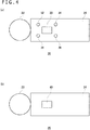
- FIG. 4 illustrates an external configuration of the input apparatus 20, and FIG. 4(a) illustrates a top surface configuration of the input apparatus 20, and FIG. 4(b) illustrates a bottom surface configuration of the input apparatus 20.
- the input apparatus 20 has a light-emitting body 22 and a handle 24.
- the light-emitting body 22 has an outside light-emitting device made of a light-transmitting resin formed in a spherical shape and a light-emitting diode or an electric bulb therein. When the light-emitting device therein emits light, the entire outside spherical body shines.
- Operating buttons 30, 32, 34, 36, and 38 are provided on the top surface of the handle 24, and an operating button 40 is provided on the bottom surface thereof.
- the user operates the operating buttons 30, 32, 34, 36, and 38 with the thumb and the operating button 40 with the index finger while holding an end portion of the handle 24 with the hand.
- the operating buttons 30, 32, 34, 36, and 38 include pushbuttons and are operated as the user presses them.
- the operating button 40 may be a button that permits entry of an analog amount.
- the user plays a game while watching a game screen displayed on the display apparatus 12.
- the imaging apparatus 14 needs to image the light-emitting body 22 during execution of a game application. Therefore, an imaging range thereof is preferably arranged to face the same direction as the display apparatus 12. In general, the user often plays games in front of the display apparatus 12. Therefore, the imaging apparatus 14 is arranged such that an optical axis thereof matches a front direction of the display apparatus 12. Specifically, the imaging apparatus 14 is preferably arranged near the display apparatus 12 such that the imaging range thereof includes a position where the user can visually recognize the display screen of the display apparatus 12. This allows the imaging apparatus 14 to image the input apparatus 20.
- FIG. 5 illustrates an internal configuration of the input apparatus 20.
- the input apparatus 20 includes a wireless communication module 48, a processing section 50, a light-emitting section 62, and the operating buttons 30, 32, 34, 36, 38, and 40.
- the wireless communication module 48 has a function to send and receive data to and from a wireless communication module of the gaming apparatus 10.
- the processing section 50 performs predetermined processes in the input apparatus 20.
- the processing section 50 includes a main control section 52, an input acceptance section 54, a triaxial acceleration sensor 56, a triaxial gyrosensor 58, and a light emission control section 60.
- the main control section 52 sends and receives necessary data to and from the wireless communication module 48.
- the input acceptance section 54 accepts input information from the operating buttons 30, 32, 34, 36, 38, and 40 and sends input information to the main control section 52.
- the triaxial acceleration sensor 56 detects acceleration components of three axial directions of X, Y, and Z.
- the triaxial gyrosensor 58 detects angular speeds on XZ, ZY, and YX planes. It should be noted that, here, width, height, and length directions of the input apparatus 20 are specified as X, Y, and Z axes.
- the triaxial acceleration sensor 56 and the triaxial gyrosensor 58 are preferably arranged inside the handle 24 and near the center inside the handle 24.
- the wireless communication module 48 sends, together with input information from the operating buttons, detection value information obtained by the triaxial acceleration sensor 56 and detection value information obtained by the triaxial gyrosensor 58, to the wireless communication module of the gaming apparatus 10 at a given interval.
- This transmission interval is set, for example, at 11.25 milliseconds.
- the light emission control section 60 controls light emission of the light-emitting section 62.
- the light-emitting section 62 has a red light-emitting diode (LED) 64a, a green LED 64b, and a blue LED 64c, thereby allowing them to emit light in a plurality of colors.
- the light emission control section 60 causes the light-emitting section 62 to emit light in a desired color by controlling light emission of the red LED 64a, the green LED 64b, and the blue LED 64c.
- the wireless communication module 48 supplies the light emission instruction to the main control section 52.
- the main control section 52 supplies the light emission instruction to the light emission control section 60.
- the light emission control section 60 controls light emission of the red LED 64a, the green LED 64b, and the blue LED 64c such that the light-emitting section 62 emits light in the color specified by the light emission instruction.
- the light emission control section 60 may control lighting of each LED through pulse width modulation (PWM) control.
- PWM pulse width modulation
- FIG. 6 illustrates a configuration of the gaming apparatus 10.
- the gaming apparatus 10 includes a frame image acquisition section 80, an image processing section 82, a device information deriving section 84, a wireless communication module 86, an input acceptance section 88, an output section 90, and an application processing section 300.
- the processing capability of the gaming apparatus 10 in the present embodiment is realized by a central processing unit (CPU), a memory, and a program loaded into the memory, and so on.
- CPU central processing unit
- the program may be built into the gaming apparatus 10.
- the program may be externally supplied stored in a recording medium. Therefore, it is to be understood by those skilled in the art that these functional blocks can be realized in various ways by hardware alone, software alone, or a combination thereof.
- the gaming apparatus 10 may have a plurality of CPUs from a viewpoint of hardware configuration.
- the wireless communication module 86 establishes wireless communication with the wireless communication module 48 of the input apparatus 20. This allows the input apparatus 20 to send operating button state information and detection value information of the triaxial acceleration sensor 56 and the triaxial gyrosensor 58 to the gaming apparatus 10 at a given interval.
- the wireless communication module 86 receives operating button state information and sensor detection value information sent from the input apparatus 20 and supplies them to the input acceptance section 88.
- the input acceptance section 88 separates button state information and sensor detection value information and hands them over to the application processing section 300.
- the application processing section 300 receives button state information and sensor detection value information as a game operation instruction.
- the application processing section 300 treats sensor detection value information as attitude information of the input apparatus 20.
- the frame image acquisition section 80 is configured as a USB interface and acquires frame images at a given imaging speed (e.g., 30 frames/second) from the imaging apparatus 14.
- the image processing section 82 extracts a light-emitting body image from a frame image.
- the image processing section 82 identifies the position and size of the light-emitting body in the frame images. For example, as the light-emitting body 22 of the input apparatus 20 emits light in a color that is unlikely used in the user's environment, the image processing section 82 can extract a light-emitting body image from a frame image with high accuracy.
- the image processing section 82 may generate a binarized image by binarizing frame image data using a given threshold.
- This binarization encodes a pixel value of a pixel having luminance higher than the given threshold as "1” and the pixel value of a pixel having luminance equal to or lower than the given threshold as "0.”
- the image processing section 82 can identify the position and size of the light-emitting body image from the binarized image. For example, the image processing section 82 identifies coordinates of a center of gravity and a radius of the light-emitting body image in the frame image.
- the device information deriving section 84 derives position information of the input apparatus 20 and the head-mounted display 100 as seen from the imaging apparatus 14 from the position and size of the light-emitting body image identified by the image processing section 82.
- the device information deriving section 84 derives position coordinates in camera coordinates from the center of gravity of the light-emitting body image and also derives distance information from the imaging apparatus 14 from the radius of the light-emitting body image.
- the position coordinates and the distance information make up position information of the input apparatus 20 and the head-mounted display 100.
- the device information deriving section 84 derives position information of the input apparatus 20 and the head-mounted display 100 for each frame image and hands over position information to the application processing section 300.
- the application processing section 300 receives position information of the input apparatus 20 and the head-mounted display 100 as a game operation instruction.
- the application processing section 300 progresses the game from position information and attitude information of the input apparatus 20 and button state information and generates an image signal indicating processing results of the game application.
- the image signal is sent to the display apparatus 12 from the output section 90 and output as a display image.
- FIG. 7 is a functional configuration diagram of the gaming apparatus 10.
- the application processing section 300 of the gaming apparatus 10 includes a control section 310 and a data holding section 360.
- the control section 310 includes a game control section 311, an instruction input acquisition section 312, an HMD information acquisition section 314, an input apparatus information acquisition section 315, a first image generation section 316, and a second image generation section 317.
- the data holding section 360 holds program data of games executed in the gaming apparatus 10, various data used by the game programs, and so on.
- the instruction input acquisition section 312 acquires information related to user instruction input accepted by the input apparatus 20 or the head-mounted display 100 from the input apparatus 20 or the head-mounted display 100.
- the HMD information acquisition section 314 acquires information related to the attitude of the head-mounted display from the head-mounted display 100. Also, the HMD information acquisition section 314 acquires information related to the position of the head-mounted display 100 from the device information deriving section 84. These pieces of information are conveyed to the game control section 311. Information related to the attitude of the head-mounted display 100 may be acquired by the device information deriving section 84 analyzing a captured image of the head-mounted display 100.
- the input apparatus information acquisition section 315 acquires information related to the attitude of the input apparatus 20. Also, the input apparatus information acquisition section 315 acquires information related to the position of the input apparatus 20 from the device information deriving section 84. These pieces of information are conveyed to the game control section 311. Information related to the attitude of the input apparatus 20 may be acquired by the device information deriving section 84 analyzing a captured image of the input apparatus 20.
- the input apparatus information acquisition section 315 calculates the position of the input apparatus 20 based on the previously acquired position of the input apparatus 20 and information related to the attitude of the input apparatus 20 acquired after that point in time. For example, the current position of the input apparatus 20 may be calculated by calculating a deviation from the previously acquired position of the input apparatus 20 based on translational acceleration data acquired from the acceleration sensor of the input apparatus 20. While the input apparatus 20 is not imaged by the imaging apparatus 14, the position of the input apparatus 20 is successively calculated in the similar manner.
- the position of the input apparatus 20 newly calculated by the device information deriving section 84 may be used as the current position of the input apparatus 20. The same is true for the head-mounted display 100.
- the game control section 311 executes the game program and progresses the game based on user instruction input acquired by the instruction input acquisition section 312 and information related to the position or attitude of the input apparatus 20 or the head-mounted display 100.
- the game control section 311 changes the position of a player's character, an operation target, based on input made by directional keys or an analog stick of the input apparatus 20 and a change in position of the input apparatus 20 or the head-mounted display 100 in a game field made up of a virtual three-dimensional (3D) space.
- the first image generation section 316 generates an image to be displayed on the head-mounted display 100.
- the first image generation section 316 generates a game field image by specifying a viewpoint position based on the position of the operation target controlled by the game control section 311, specifying a direction of line of sight based on the attitude of the head-mounted display 100, and rendering a virtual 3D space.
- the first image generation section 316 associates the attitude of the head-mounted display 100 and the direction of line of sight in the game field at a given time and changes, thereafter, the direction of line of sight with change in the attitude of the head-mounted display 100.
- the user can look over the game field by actually moving his or her head, allowing the user to feel as if he or she were really in the game field.
- the first image generation section 316 generates a first image by adding information related to the game, an image to be displayed on the head-mounted display 100, and so on to the generated game field image.
- the first image generated by the first image generation section 316 is sent to the head-mounted display 100 via a wireless communication module or a wired communication module.
- the second image generation section 317 generates an image to be displayed on the display apparatus 12.
- the first image generated by the first image generation section 316 is also sent to the display apparatus 12.
- the second image generation section 317 When an image different from the image displayed on the head-mounted display 100 is displayed on the display apparatus 12, an example of which is when the user wearing the head-mounted display 100 and the user watching the display apparatus 12 execute a head-to-head game, the second image generation section 317 generates a game field image by specifying a viewpoint position and a direction of line of sight different from those specified by the first image generation section 316.
- the second image generation section 317 generates a second image by adding information related to the game, an image to be displayed on the display apparatus 12, and so on to the generated game field image.
- the second image generated by the second image generation section 317 is sent to the display apparatus 12 via a wireless communication module or a wired communication module.
- FIG. 8 illustrates examples of images displayed on the head-mounted display.
- the game control section 311 provides a function to switch the viewpoint position between a plurality of positions specified in the game field.
- a game field image is displayed that was generated with one of a plurality of positions specified in the game field as a viewpoint position.
- markers 500 and 502 further appear that indicate positions specified as viewpoint positions in the game field.
- the direction of line of sight may be changed by further taking into account the user's line of sight.
- the user's line of sight may be detected by using a known and arbitrary line-of-sight tracking technology.
- the game control section 311 causes the first image generation section 316 to change the manner in which the marker 500 is displayed, thereby indicating that the position depicted by the marker 500 has been selected as a candidate for specifying a viewpoint position.
- the game control section 311 instructs the first image generation section 316 to change the viewpoint position to the position depicted by the selected marker 500.
- the first image generation section 316 generates and displays a game field image having the position of the marker 500 as a viewpoint position as depicted in FIG. 8(c) .
- a marker 504 appears that indicates the position specified as the viewpoint position in the display screen depicted in FIG. 8(a) .
- FIG. 9 is a schematic diagram for describing a method of specifying a viewpoint position and a direction of line of sight.
- a viewpoint position is specified on the surface of a sphere having its center near a center of the game field, and a default direction of line of sight is specified in the direction of seeing the first position near the center of the game field from the viewpoint position.
- the first image generation section 316 smoothly moves the viewpoint position along the sphere surface and generates a game field image by specifying a direction of line of sight in the direction of seeing the first position in the game field from the viewpoint position even while moving the viewpoint position.
- a viewpoint position may be provided on the surface of a sphere or a spheroid having its center at an arbitrary point in the game field or on a curved surface other than that.
- the viewpoint position may be continuously changed in a linear or curved manner from the viewpoint position before the change to the viewpoint position after the change.
- the surface of a lower hemisphere is underground. Therefore, a viewpoint position can be specified only on the surface of an upper hemisphere.
- viewpoint positions may be specified on the surface of the lower hemisphere.
- FIG. 10 illustrates examples of images displayed on the head-mounted display. If the user moves the head-mounted display 100 forward by moving his or her head forward when a game field image as seen from a viewpoint position is displayed as depicted in FIG. 10(a) , the game control section 311 causes the first image generation section 316 to move the viewpoint position to a second position near the center of the game field.
- the game control section 311 may move the viewpoint position when the head-mounted display 100 is moved forward by as much as or more than a given amount of travel. Alternatively, the game control section 311 may move the viewpoint position when the head-mounted display 100 travels at a speed equal to or more than a given value.
- the viewpoint position can be moved to near the center of the game field from spectators' seats as depicted in FIG. 10(b) . Therefore, the user who was watching, for example, a soccer game from a spectator's viewpoint can feel as if he or she entered the field where the game is taking place. Also, it is possible to provide an easy-to-understand method of moving the viewpoint using the head-mounted display 100.
- FIG. 11 is a schematic diagram for describing details of another game provided by the game control section.
- the user hides inside a box 510 having holes 512 and pops up his or her face from a hole 512 while being careful not to be hit by a hammer 514 and reads letters written on a plate 516.
- the game control section 311 changes the viewpoint position based on the position of the head-mounted display 100.
- the game control section 311 determines the hole 512 to be hit with the hammer 514 at a given timing and swings down the hammer 514 into the determined hole 512.
- FIG. 12 depicts diagrams illustrating examples of images displayed on the head-mounted display.
- FIG. 12(a) depicts a game screen when the user looks up from the middle hole. The hammer is about to be swung down into the middle hole.
- FIG. 12(b) depicts a game screen when the user has moved the viewpoint position to under the right hole by moving the head-mounted display 100 to the right. Because the hammer is about to be swung down into the middle hole, the hammer will not be swung down into the right hole for a while. At this time, if the user moves up the viewpoint position from the right hole by moving up the head-mounted display 100, the user can visually recognize the letters written on a plate provided outside the box as depicted in FIG. 12(c) .
- FIG. 13 is a schematic diagram for describing a method of moving the viewpoint position in a game according to the embodiment.
- the hip position is fixed. Therefore, the user moves his or her head in a circular arc.
- the possible range of head motion that causes no hindrance to the game is approximately 100 to 120 degrees at most.
- the game control section 311 moves the viewpoint position to a greater extent when the head-mounted display 100 is moved horizontally than when the head-mounted display 100 is moved perpendicularly.
- the amount of travel exceeds the amount equivalent to the width of the middle hole when the head-mounted display 100 is moved to the left or right, the area between the middle hole and the left or right hole is skipped, moving the viewpoint position to under the left or right hole. Specifically, if the head-mounted display 100 is moved to the right while the viewpoint position is located under the middle hole, and when the head-mounted display 100 reaches a position 520, the viewpoint position jumps from the right edge position of the middle hole to the left edge position of the right hole.
- the viewpoint position jumps from the left edge position of the right hole to the right edge position of the middle hole.
- the viewpoint position is not moved to an area to which there is no or only a slight need to move the viewpoint position in a game, whereas the viewpoint position can be moved to only given areas to which there is need to move the viewpoint position or to which the viewpoint position is often moved, thereby making effective use of the possible motion range of the head-mounted display 100 and moving the viewpoint position.
- a hysteresis is provided by using different positions, the position 520 for causing the viewpoint position to jump for rightward movement and the position 522 for causing the viewpoint position to jump for leftward movement, thereby reducing the likelihood for the viewpoint position to jump to the left and right frequently when the head-mounted display 100 is at an angle equivalent to a position in the neighborhood of a threshold.
- the viewpoint position When an attempt is made to move the viewpoint position to above the left or right hole, it is necessary to move the head-mounted display 100 upward while keeping the head-mounted display 100 tilted to the left or right. However, it is not easy for the user to move his or her head straight upward while keeping the body tilted to the left or right. In the present embodiment, therefore, when the head-mounted display 100 is moved up or down in a tilted position to the left or right, and even if the direction of movement is tilted diagonally, the game control section 311 moves the viewpoint position vertically, but not horizontally.
- the game control section 311 moves the viewpoint position vertically by the amount of travel equivalent to a vertical component of a movement vector of the head-mounted display 100 and may ignore a horizontal component or move the viewpoint position vertically by the amount of travel equivalent to the magnitude of the movement vector of the head-mounted display 100.
- the viewpoint position is changed in response to movement of the head-mounted display 100, it is possible to restrict the movement direction of the viewpoint position to a given direction and prevent the viewpoint position from moving in an unnecessary direction by converting the movement vector of the head-mounted display 100 into a vector in a given direction.
- Such a technology is applicable, for example, to a game in which a player's character hides behind an obstacle such as wall to ward off oncoming bullets.
- an image for binocular stereopsis was displayed on the display apparatus 190 of the head-mounted display 100 in the above example, an image for monocular stereopsis may be displayed in a different example.
- the head-mounted display 100 was used in a game system in the above example, the technology described in the embodiment can be also used to display content other than games.
- Gaming apparatus 10 Gaming apparatus, 20 Input apparatus, 100 Head-mounted display, 190 Display apparatus, 311 Game control section, 312 Instruction input acquisition section, 314 HMD information acquisition section, 315 Input apparatus information acquisition section, 316 First image generation section, 317 Second image generation section.
- the present invention is applicable to a display control apparatus for controlling display to a head-mounted display.
Abstract
Description
- The present invention relates to a display control technology, and more particularly, to a display control apparatus and a display control method for controlling display on a head-mounted display.
- Games are played by wearing a head-mounted display, connected to a game console, on the head, watching a screen displayed on the head-mounted display, and manipulating a controller or other device. With an ordinary stationary display, a user's field-of-view range spreads outside the display screen, possibly making it impossible to focus one's attention on the display screen or resulting in insufficient sense of immersion. In that respect, when a head-mounted display is worn, a user cannot see anything other than an image appearing on the head-mounted display, thereby increasing a sense of immersion into the image world and further enhancing the entertaining nature of the game.
- The inventor recognized the need for a more convenient display control technology to ensure that games using a head-mounted display can be enjoyed by more user segments.
- In order to solve the above problem, a display control apparatus according to a mode of the present invention includes a display control section that generates a virtual space image by specifying a viewpoint position and a direction of line of sight and displays the image on a head-mounted display. The display control section can specify a plurality of positions in the virtual space as viewpoint positions and can change the viewpoint position to a position determined from among the plurality of positions in accordance with an attitude of the head-mounted display, and when the viewpoint position is changed, the display control section specifies, as a direction of line of sight, the direction in which a first position in the virtual space is seen from the changed viewpoint position.
- Another mode of the present invention is a display control apparatus. This apparatus includes a display control section and a viewpoint position control section. The display control section generates a virtual space image by specifying a viewpoint position and a direction of line of sight and displays the image on a head-mounted display. The viewpoint position control section moves the viewpoint position in accordance with a position of the head-mounted display. The viewpoint position control section moves the viewpoint position to a greater extent when the head-mounted display is moved horizontally than when the head-mounted display is moved perpendicularly.
- It should be noted that arbitrary combinations of the above components and conversions of expressions of the present invention between method, apparatus, system, program, and so on are also effective as modes of the present invention.
- According to the present invention, it is possible to improve convenience of head-mounted display users.
-
- [
FIG. 1 ]
FIG. 1 is a diagram illustrating an environment in which a game system according to an embodiment is used. - [
FIG. 2 ]
FIG. 2 is an external view of a head-mounted display according to the embodiment. - [
FIG. 3 ]
FIG. 3 is a functional configuration diagram of the head-mounted display. - [
FIG. 4 ]
FIG. 4 depicts diagrams illustrating an external configuration of an input apparatus. - [
FIG. 5 ]
FIG. 5 is a diagram illustrating an internal configuration of the input apparatus. - [
FIG. 6 ]
FIG. 6 is a diagram illustrating a configuration of a gaming apparatus. - [
FIG. 7 ]
FIG. 7 is a functional configuration diagram of the gaming apparatus. - [
FIG. 8 ]
FIGS. 8(a) to 8(c) are diagrams illustrating examples of images displayed on the head-mounted display. - [
FIG. 9 ]
FIG. 9 is a schematic diagram for describing a method of specifying a viewpoint position and a direction of line of sight. - [
FIG. 10 ]
FIGS. 10(a) and 10(b) are diagrams illustrating examples of images displayed on the head-mounted display. - [
FIG. 11 ]
FIG. 11 is a schematic diagram for describing details of another game provided by a game control section. - [
FIG. 12 ]
FIGS. 12(a) to 12(c) are diagrams illustrating examples of images displayed on the head-mounted display. - [
FIG. 13 ]
FIG. 13 is a schematic diagram for describing a method of moving the viewpoint position in a game according to the embodiment. - In the present embodiment, a description will be given of a display technology using a head-mounted display (HMD). A head-mounted display is a display apparatus worn on a user's head in such a manner as to cover his or her eyes so that the user can view still images and videos appearing on a display screen provided in front of user's eyes. What appears on the head-mounted display may be content such as movies and television (TV) programs. In the present embodiment, however, a description will be given of an example in which a head-mounted display is used as a display apparatus for displaying game images.
-
FIG. 1 is a diagram illustrating an environment in which agame system 1 according to an embodiment is used. Thegame system 1 includes agaming apparatus 10, aninput apparatus 20, animaging apparatus 14, a head-mounteddisplay 100, and adisplay apparatus 12. Thegaming apparatus 10 executes a game program. Theinput apparatus 20 is used to input a user instruction to thegaming apparatus 10. Theimaging apparatus 14 images a real space around a user. The head-mounteddisplay 100 displays a first game image generated by thegaming apparatus 10. Thedisplay apparatus 12 displays a second game image generated by thegaming apparatus 10. - The
gaming apparatus 10 executes a game program based on an instruction input supplied from theinput apparatus 20 or the head-mounteddisplay 100, a position or attitude of theinput apparatus 20 or the head-mounteddisplay 100, and so on, generates a first game image and transports the image to the head-mounteddisplay 100, and generates a second game image and transports the image to thedisplay apparatus 12. - The head-mounted
display 100 displays the first game image generated by thegaming apparatus 10. The head-mounteddisplay 100 also transports, to thegaming apparatus 10, information related to user input to the input apparatus provided on the head-mounteddisplay 100. The head-mounteddisplay 100 may be connected to thegaming apparatus 10 with a wired cable. Alternatively, the head-mounteddisplay 100 may be connected wirelessly through wireless local area network (LAN) or other means. - The
display apparatus 12 displays a second game image generated by thegaming apparatus 10. Thedisplay apparatus 12 may be a TV having a display and a speaker. Alternatively, thedisplay apparatus 12 may be a computer display or other apparatus. - The
input apparatus 20 has a function to transport user instruction input to thegaming apparatus 10 and is configured as a wireless controller capable of wirelessly communicating with thegaming apparatus 10 in the present embodiment. Theinput apparatus 20 and thegaming apparatus 10 may establish wireless connection using Bluetooth (registered trademark) protocol. It should be noted that theinput apparatus 20 is not limited to a wireless controller and may be a wired controller connected to thegaming apparatus 10 via a cable. - The
input apparatus 20 is driven by batteries and is configured to have a plurality of buttons for making instruction input so as to progress the game. When the user operates a button on theinput apparatus 20, instruction input resulting from the operation is sent to thegaming apparatus 10 through wireless communication. - The
imaging apparatus 14 is a video camera that includes, for example, a charge-coupled device (CCD) imaging device or a complementary metal-oxide semiconductor (CMOS) imaging device and generates, by imaging a real space at a given interval, a frame image for each interval. Theimaging apparatus 14 is connected to thegaming apparatus 10 via a universal serial bus (USB) or other interface. An image captured by theimaging apparatus 14 is used by thegaming apparatus 10 to derive the positions and attitudes of theinput apparatus 20 and the head-mounteddisplay 100. Theimaging apparatus 14 may be a ranging camera or a stereo camera capable of acquiring a distance. In this case, theimaging apparatus 14 makes it possible to acquire the distance between theimaging apparatus 14 and theinput apparatus 20 or the head-mounteddisplay 100. - In the
game system 1 of the present embodiment, theinput apparatus 20 and the head-mounteddisplay 100 have a light-emitting section configured to emit light in a plurality of colors. During a game, the light-emitting section emits light in the color specified by thegaming apparatus 10 and is imaged by theimaging apparatus 14. Theimaging apparatus 14 images theinput apparatus 20, generates a frame image, and supplies the image to thegaming apparatus 10. Thegaming apparatus 10 acquires the frame image and derives position information of the light-emitting section in the real space from the position and size of the image of the light-emitting section in the frame image. Thegaming apparatus 10 treats position information as a game operation instruction and reflects position information in game processing including controlling the action of a player's character. - Also, the
input apparatus 20 and the head-mounteddisplay 100 have an acceleration sensor and a gyrosensor. Sensor detection values are sent to thegaming apparatus 10 at a given interval, and thegaming apparatus 10 acquires sensor detection values and acquires attitude information of theinput apparatus 20 and the head-mounteddisplay 100 in the real space. Thegaming apparatus 10 treats attitude information as a game operation instruction and reflects attitude information in game processing. -
FIG. 2 is an external view of the head-mounteddisplay 100 according to the embodiment. The head-mounteddisplay 100 includes amain body section 110, ahead contact section 112, and a light-emittingsection 114. - The
main body section 110 includes a display, a global positioning system (GPS) unit for acquiring position information, an attitude sensor, a communication apparatus, and so on. Thehead contact section 112 may include a biological information acquisition sensor capable of measuring user's biological information such as temperature, pulse, blood components, perspiration, brain waves, and cerebral blood flow. As described above, the light-emittingsection 114 emits light in the color specified by thegaming apparatus 10 and functions as a criterion for calculating the position of the head-mounteddisplay 100 in the image captured by theimaging apparatus 14. - A camera for capturing the user's eyes may be further provided on the head-mounted
display 100. The camera mounted to the head-mounteddisplay 100 permits detection of the user's line of sight, movement of the pupils, blinking, and so on. - Although a description will be given of the head-mounted
display 100 in the present embodiment, the display control technology of the present embodiment is applicable not only to a case in which the head-mounteddisplay 100 in a narrow sense is worn but also to a case in which eyeglasses, an eyeglass-type display, an eyeglass-type camera, a headphone, a headset (microphone equipped headphone), an earphone, an earring, an ear-mounted camera, a hat, a camera-equipped hat, or hair band is worn. -
FIG. 3 is a functional configuration diagram of the head-mounteddisplay 100. The head-mounteddisplay 100 includes aninput interface 122, anoutput interface 130, abacklight 132, acommunication control section 140, anetwork adapter 142, anantenna 144, astorage section 150, aGPS unit 161, awireless unit 162, anattitude sensor 164, an external input/output (I/O)terminal interface 170, anexternal memory 172, aclock section 180, adisplay apparatus 190, and acontrol section 160. These functional blocks can also be realized by hardware alone, software alone, or a combination thereof in various forms. - The
control section 160 is a main processor that processes and outputs signals such as image signals and sensor signals, instructions, and data. Theinput interface 122 accepts an operation signal and a setup signal from input buttons and so on and supplies these signals to thecontrol section 160. Theoutput interface 130 receives an image signal from thecontrol section 160 and displays the signal on thedisplay apparatus 190. Thebacklight 132 supplies backlight to a liquid crystal display making up thedisplay apparatus 190. - The
communication control section 140 sends, to external equipment, data input from thecontrol section 160 in a wired or wireless communication manner via thenetwork adapter 142 or theantenna 144. Thecommunication control section 140 receives data from external equipment in a wired or wireless manner via thenetwork adapter 142 or theantenna 144 and outputs the data to thecontrol section 160. - The
storage section 150 temporarily stores data and parameters processed by thecontrol section 160, operation signals, and so on. - The
GPS unit 161 receives position information from a GPS satellite in accordance with an operation signal from thecontrol section 160 and supplies position information to thecontrol section 160. Thewireless unit 162 receives position information from a wireless base station in accordance with an operation signal from thecontrol section 160 and supplies position information to thecontrol section 160. - The
attitude sensor 164 detects attitude information such as orientation and tilt of themain body section 110 of the head-mounteddisplay 100. Theattitude sensor 164 is realized by combining a gyrosensor, an acceleration sensor, an angular acceleration sensor, and so on as appropriate. - The external I/
O terminal interface 170 is an interface for connecting peripheral equipment such as USB controller. Theexternal memory 172 is an external memory such as flash memory. - The
clock section 180 specifies time information using a setup signal from thecontrol section 160 and supplies time information to thecontrol section 160. -
FIG. 4 illustrates an external configuration of theinput apparatus 20, andFIG. 4(a) illustrates a top surface configuration of theinput apparatus 20, andFIG. 4(b) illustrates a bottom surface configuration of theinput apparatus 20. Theinput apparatus 20 has a light-emittingbody 22 and ahandle 24. The light-emittingbody 22 has an outside light-emitting device made of a light-transmitting resin formed in a spherical shape and a light-emitting diode or an electric bulb therein. When the light-emitting device therein emits light, the entire outside spherical body shines.Operating buttons handle 24, and anoperating button 40 is provided on the bottom surface thereof. The user operates the operatingbuttons operating button 40 with the index finger while holding an end portion of thehandle 24 with the hand. The operatingbuttons operating button 40 may be a button that permits entry of an analog amount. - The user plays a game while watching a game screen displayed on the
display apparatus 12. Theimaging apparatus 14 needs to image the light-emittingbody 22 during execution of a game application. Therefore, an imaging range thereof is preferably arranged to face the same direction as thedisplay apparatus 12. In general, the user often plays games in front of thedisplay apparatus 12. Therefore, theimaging apparatus 14 is arranged such that an optical axis thereof matches a front direction of thedisplay apparatus 12. Specifically, theimaging apparatus 14 is preferably arranged near thedisplay apparatus 12 such that the imaging range thereof includes a position where the user can visually recognize the display screen of thedisplay apparatus 12. This allows theimaging apparatus 14 to image theinput apparatus 20. -
FIG. 5 illustrates an internal configuration of theinput apparatus 20. Theinput apparatus 20 includes awireless communication module 48, aprocessing section 50, a light-emittingsection 62, and the operatingbuttons wireless communication module 48 has a function to send and receive data to and from a wireless communication module of thegaming apparatus 10. Theprocessing section 50 performs predetermined processes in theinput apparatus 20. - The
processing section 50 includes amain control section 52, aninput acceptance section 54, atriaxial acceleration sensor 56, atriaxial gyrosensor 58, and a lightemission control section 60. Themain control section 52 sends and receives necessary data to and from thewireless communication module 48. - The
input acceptance section 54 accepts input information from the operatingbuttons main control section 52. Thetriaxial acceleration sensor 56 detects acceleration components of three axial directions of X, Y, and Z. Thetriaxial gyrosensor 58 detects angular speeds on XZ, ZY, and YX planes. It should be noted that, here, width, height, and length directions of theinput apparatus 20 are specified as X, Y, and Z axes. Thetriaxial acceleration sensor 56 and thetriaxial gyrosensor 58 are preferably arranged inside thehandle 24 and near the center inside thehandle 24. Thewireless communication module 48 sends, together with input information from the operating buttons, detection value information obtained by thetriaxial acceleration sensor 56 and detection value information obtained by thetriaxial gyrosensor 58, to the wireless communication module of thegaming apparatus 10 at a given interval. This transmission interval is set, for example, at 11.25 milliseconds. - The light
emission control section 60 controls light emission of the light-emittingsection 62. The light-emittingsection 62 has a red light-emitting diode (LED) 64a, agreen LED 64b, and ablue LED 64c, thereby allowing them to emit light in a plurality of colors. The lightemission control section 60 causes the light-emittingsection 62 to emit light in a desired color by controlling light emission of thered LED 64a, thegreen LED 64b, and theblue LED 64c. - When a light emission instruction is received from the
gaming apparatus 10, thewireless communication module 48 supplies the light emission instruction to themain control section 52. Themain control section 52 supplies the light emission instruction to the lightemission control section 60. The lightemission control section 60 controls light emission of thered LED 64a, thegreen LED 64b, and theblue LED 64c such that the light-emittingsection 62 emits light in the color specified by the light emission instruction. For example, the lightemission control section 60 may control lighting of each LED through pulse width modulation (PWM) control. -
FIG. 6 illustrates a configuration of thegaming apparatus 10. Thegaming apparatus 10 includes a frameimage acquisition section 80, animage processing section 82, a deviceinformation deriving section 84, awireless communication module 86, aninput acceptance section 88, anoutput section 90, and anapplication processing section 300. The processing capability of thegaming apparatus 10 in the present embodiment is realized by a central processing unit (CPU), a memory, and a program loaded into the memory, and so on. Here, a configuration is depicted that is realized by these components working with each other in a coordinated fashion. The program may be built into thegaming apparatus 10. Alternatively, the program may be externally supplied stored in a recording medium. Therefore, it is to be understood by those skilled in the art that these functional blocks can be realized in various ways by hardware alone, software alone, or a combination thereof. It should be noted that thegaming apparatus 10 may have a plurality of CPUs from a viewpoint of hardware configuration. - The
wireless communication module 86 establishes wireless communication with thewireless communication module 48 of theinput apparatus 20. This allows theinput apparatus 20 to send operating button state information and detection value information of thetriaxial acceleration sensor 56 and thetriaxial gyrosensor 58 to thegaming apparatus 10 at a given interval. - The
wireless communication module 86 receives operating button state information and sensor detection value information sent from theinput apparatus 20 and supplies them to theinput acceptance section 88. Theinput acceptance section 88 separates button state information and sensor detection value information and hands them over to theapplication processing section 300. Theapplication processing section 300 receives button state information and sensor detection value information as a game operation instruction. Theapplication processing section 300 treats sensor detection value information as attitude information of theinput apparatus 20. - The frame
image acquisition section 80 is configured as a USB interface and acquires frame images at a given imaging speed (e.g., 30 frames/second) from theimaging apparatus 14. Theimage processing section 82 extracts a light-emitting body image from a frame image. Theimage processing section 82 identifies the position and size of the light-emitting body in the frame images. For example, as the light-emittingbody 22 of theinput apparatus 20 emits light in a color that is unlikely used in the user's environment, theimage processing section 82 can extract a light-emitting body image from a frame image with high accuracy. Theimage processing section 82 may generate a binarized image by binarizing frame image data using a given threshold. This binarization encodes a pixel value of a pixel having luminance higher than the given threshold as "1" and the pixel value of a pixel having luminance equal to or lower than the given threshold as "0." By causing the light-emittingbody 22 to light up at luminance beyond this given threshold, theimage processing section 82 can identify the position and size of the light-emitting body image from the binarized image. For example, theimage processing section 82 identifies coordinates of a center of gravity and a radius of the light-emitting body image in the frame image. - The device
information deriving section 84 derives position information of theinput apparatus 20 and the head-mounteddisplay 100 as seen from theimaging apparatus 14 from the position and size of the light-emitting body image identified by theimage processing section 82. The deviceinformation deriving section 84 derives position coordinates in camera coordinates from the center of gravity of the light-emitting body image and also derives distance information from theimaging apparatus 14 from the radius of the light-emitting body image. The position coordinates and the distance information make up position information of theinput apparatus 20 and the head-mounteddisplay 100. The deviceinformation deriving section 84 derives position information of theinput apparatus 20 and the head-mounteddisplay 100 for each frame image and hands over position information to theapplication processing section 300. Theapplication processing section 300 receives position information of theinput apparatus 20 and the head-mounteddisplay 100 as a game operation instruction. - The
application processing section 300 progresses the game from position information and attitude information of theinput apparatus 20 and button state information and generates an image signal indicating processing results of the game application. The image signal is sent to thedisplay apparatus 12 from theoutput section 90 and output as a display image. -
FIG. 7 is a functional configuration diagram of thegaming apparatus 10. Theapplication processing section 300 of thegaming apparatus 10 includes acontrol section 310 and adata holding section 360. Thecontrol section 310 includes agame control section 311, an instructioninput acquisition section 312, an HMDinformation acquisition section 314, an input apparatusinformation acquisition section 315, a firstimage generation section 316, and a secondimage generation section 317. - The
data holding section 360 holds program data of games executed in thegaming apparatus 10, various data used by the game programs, and so on. - The instruction
input acquisition section 312 acquires information related to user instruction input accepted by theinput apparatus 20 or the head-mounteddisplay 100 from theinput apparatus 20 or the head-mounteddisplay 100. - The HMD
information acquisition section 314 acquires information related to the attitude of the head-mounted display from the head-mounteddisplay 100. Also, the HMDinformation acquisition section 314 acquires information related to the position of the head-mounteddisplay 100 from the deviceinformation deriving section 84. These pieces of information are conveyed to thegame control section 311. Information related to the attitude of the head-mounteddisplay 100 may be acquired by the deviceinformation deriving section 84 analyzing a captured image of the head-mounteddisplay 100. - The input apparatus
information acquisition section 315 acquires information related to the attitude of theinput apparatus 20. Also, the input apparatusinformation acquisition section 315 acquires information related to the position of theinput apparatus 20 from the deviceinformation deriving section 84. These pieces of information are conveyed to thegame control section 311. Information related to the attitude of theinput apparatus 20 may be acquired by the deviceinformation deriving section 84 analyzing a captured image of theinput apparatus 20. - If the
input apparatus 20 moves out of the imaging range of theimaging apparatus 14 or if theinput apparatus 20 is hidden behind the user's body or an obstacle and fails to be imaged by theimaging apparatus 14, the input apparatusinformation acquisition section 315 calculates the position of theinput apparatus 20 based on the previously acquired position of theinput apparatus 20 and information related to the attitude of theinput apparatus 20 acquired after that point in time. For example, the current position of theinput apparatus 20 may be calculated by calculating a deviation from the previously acquired position of theinput apparatus 20 based on translational acceleration data acquired from the acceleration sensor of theinput apparatus 20. While theinput apparatus 20 is not imaged by theimaging apparatus 14, the position of theinput apparatus 20 is successively calculated in the similar manner. When theinput apparatus 20 is imaged again by theimaging apparatus 14, there is a possibility that the position of theinput apparatus 20 successively calculated from acceleration data may not indicate a correct position due to cumulative drift error. Therefore, the position of theinput apparatus 20 newly calculated by the deviceinformation deriving section 84 may be used as the current position of theinput apparatus 20. The same is true for the head-mounteddisplay 100. - The
game control section 311 executes the game program and progresses the game based on user instruction input acquired by the instructioninput acquisition section 312 and information related to the position or attitude of theinput apparatus 20 or the head-mounteddisplay 100. Thegame control section 311 changes the position of a player's character, an operation target, based on input made by directional keys or an analog stick of theinput apparatus 20 and a change in position of theinput apparatus 20 or the head-mounteddisplay 100 in a game field made up of a virtual three-dimensional (3D) space. - The first
image generation section 316 generates an image to be displayed on the head-mounteddisplay 100. The firstimage generation section 316 generates a game field image by specifying a viewpoint position based on the position of the operation target controlled by thegame control section 311, specifying a direction of line of sight based on the attitude of the head-mounteddisplay 100, and rendering a virtual 3D space. The firstimage generation section 316 associates the attitude of the head-mounteddisplay 100 and the direction of line of sight in the game field at a given time and changes, thereafter, the direction of line of sight with change in the attitude of the head-mounteddisplay 100. As a result, the user can look over the game field by actually moving his or her head, allowing the user to feel as if he or she were really in the game field. The firstimage generation section 316 generates a first image by adding information related to the game, an image to be displayed on the head-mounteddisplay 100, and so on to the generated game field image. The first image generated by the firstimage generation section 316 is sent to the head-mounteddisplay 100 via a wireless communication module or a wired communication module. - The second
image generation section 317 generates an image to be displayed on thedisplay apparatus 12. When the same image as displayed on the head-mounteddisplay 100 is displayed on thedisplay apparatus 12, the first image generated by the firstimage generation section 316 is also sent to thedisplay apparatus 12. When an image different from the image displayed on the head-mounteddisplay 100 is displayed on thedisplay apparatus 12, an example of which is when the user wearing the head-mounteddisplay 100 and the user watching thedisplay apparatus 12 execute a head-to-head game, the secondimage generation section 317 generates a game field image by specifying a viewpoint position and a direction of line of sight different from those specified by the firstimage generation section 316. The secondimage generation section 317 generates a second image by adding information related to the game, an image to be displayed on thedisplay apparatus 12, and so on to the generated game field image. The second image generated by the secondimage generation section 317 is sent to thedisplay apparatus 12 via a wireless communication module or a wired communication module. -
FIG. 8 illustrates examples of images displayed on the head-mounted display. Thegame control section 311 provides a function to switch the viewpoint position between a plurality of positions specified in the game field. In the display screen depicted inFIG. 8(a) , a game field image is displayed that was generated with one of a plurality of positions specified in the game field as a viewpoint position. In the display screen,markers display 100 by shaking his or her head horizontally and vertically, the firstimage generation section 316 changes a direction of line of sight in accordance with an attitude of the head-mounteddisplay 100. When it is rendered possible to detect the user's direction of line of sight by providing a camera for shooting the user's eyeballs inside the head-mounteddisplay 100, the direction of line of sight may be changed by further taking into account the user's line of sight. The user's line of sight may be detected by using a known and arbitrary line-of-sight tracking technology. - When the marker enters a given range specified near the center of the display screen as the user points his or her face or line of sight toward the marker direction, as depicted in
FIG. 8(b) , thegame control section 311 causes the firstimage generation section 316 to change the manner in which themarker 500 is displayed, thereby indicating that the position depicted by themarker 500 has been selected as a candidate for specifying a viewpoint position. When the user issues an instruction to change the viewpoint position, for example, by pressing a given button or performing a given gesture with the candidate for specifying a viewpoint position selected, thegame control section 311 instructs the firstimage generation section 316 to change the viewpoint position to the position depicted by the selectedmarker 500. The firstimage generation section 316 generates and displays a game field image having the position of themarker 500 as a viewpoint position as depicted inFIG. 8(c) . In the display screen depicted inFIG. 8(c) , amarker 504 appears that indicates the position specified as the viewpoint position in the display screen depicted inFIG. 8(a) . -
FIG. 9 is a schematic diagram for describing a method of specifying a viewpoint position and a direction of line of sight. In the present embodiment, a viewpoint position is specified on the surface of a sphere having its center near a center of the game field, and a default direction of line of sight is specified in the direction of seeing the first position near the center of the game field from the viewpoint position. As a result, no matter where the viewpoint position is specified, it is possible to display an image that allows the game field to be overlooked. When changing the viewpoint position, the firstimage generation section 316 smoothly moves the viewpoint position along the sphere surface and generates a game field image by specifying a direction of line of sight in the direction of seeing the first position in the game field from the viewpoint position even while moving the viewpoint position. As a result, it is possible to display an image that allows the game field to be overlooked even while the viewpoint position is changed, thereby making it possible to indicate, in an easy-to-understand manner, to the user where the viewpoint position will be moved even when the viewpoint position is moved to a large extent. It should be noted that a viewpoint position may be provided on the surface of a sphere or a spheroid having its center at an arbitrary point in the game field or on a curved surface other than that. Also, when the viewpoint position is changed, the viewpoint position may be continuously changed in a linear or curved manner from the viewpoint position before the change to the viewpoint position after the change. In the example depicted inFIG. 8 , the surface of a lower hemisphere is underground. Therefore, a viewpoint position can be specified only on the surface of an upper hemisphere. However, when the game field is, for example, an outer space, viewpoint positions may be specified on the surface of the lower hemisphere. -
FIG. 10 illustrates examples of images displayed on the head-mounted display. If the user moves the head-mounteddisplay 100 forward by moving his or her head forward when a game field image as seen from a viewpoint position is displayed as depicted inFIG. 10(a) , thegame control section 311 causes the firstimage generation section 316 to move the viewpoint position to a second position near the center of the game field. Thegame control section 311 may move the viewpoint position when the head-mounteddisplay 100 is moved forward by as much as or more than a given amount of travel. Alternatively, thegame control section 311 may move the viewpoint position when the head-mounteddisplay 100 travels at a speed equal to or more than a given value. As a result, the viewpoint position can be moved to near the center of the game field from spectators' seats as depicted inFIG. 10(b) . Therefore, the user who was watching, for example, a soccer game from a spectator's viewpoint can feel as if he or she entered the field where the game is taking place. Also, it is possible to provide an easy-to-understand method of moving the viewpoint using the head-mounteddisplay 100. -
FIG. 11 is a schematic diagram for describing details of another game provided by the game control section. In the game depicted in the present figure, the user hides inside abox 510 havingholes 512 and pops up his or her face from ahole 512 while being careful not to be hit by ahammer 514 and reads letters written on aplate 516. Thegame control section 311 changes the viewpoint position based on the position of the head-mounteddisplay 100. Thegame control section 311 determines thehole 512 to be hit with thehammer 514 at a given timing and swings down thehammer 514 into thedetermined hole 512. We assume that if thehammer 514 is swung down into thehole 512 when the user's viewpoint position is above and outside thehole 512, the user is hit with thehammer 514. If the user is hit a given number of times or more with thehammer 514, the game is over. -
FIG. 12 depicts diagrams illustrating examples of images displayed on the head-mounted display.FIG. 12(a) depicts a game screen when the user looks up from the middle hole. The hammer is about to be swung down into the middle hole.FIG. 12(b) depicts a game screen when the user has moved the viewpoint position to under the right hole by moving the head-mounteddisplay 100 to the right. Because the hammer is about to be swung down into the middle hole, the hammer will not be swung down into the right hole for a while. At this time, if the user moves up the viewpoint position from the right hole by moving up the head-mounteddisplay 100, the user can visually recognize the letters written on a plate provided outside the box as depicted inFIG. 12(c) . -
FIG. 13 is a schematic diagram for describing a method of moving the viewpoint position in a game according to the embodiment. When the user plays a game seated, for example, in a chair, the hip position is fixed. Therefore, the user moves his or her head in a circular arc. However, the possible range of head motion that causes no hindrance to the game is approximately 100 to 120 degrees at most. In order to make effective use of the possible motion range of the head-mounteddisplay 100, therefore, thegame control section 311 moves the viewpoint position to a greater extent when the head-mounteddisplay 100 is moved horizontally than when the head-mounteddisplay 100 is moved perpendicularly. Also, if the amount of travel exceeds the amount equivalent to the width of the middle hole when the head-mounteddisplay 100 is moved to the left or right, the area between the middle hole and the left or right hole is skipped, moving the viewpoint position to under the left or right hole. Specifically, if the head-mounteddisplay 100 is moved to the right while the viewpoint position is located under the middle hole, and when the head-mounteddisplay 100 reaches aposition 520, the viewpoint position jumps from the right edge position of the middle hole to the left edge position of the right hole. Also, if the head-mounteddisplay 100 is moved to the left while the viewpoint position is located under the right hole, and when the head-mounteddisplay 100 reaches aposition 522, the viewpoint position jumps from the left edge position of the right hole to the right edge position of the middle hole. As a result, the viewpoint position is not moved to an area to which there is no or only a slight need to move the viewpoint position in a game, whereas the viewpoint position can be moved to only given areas to which there is need to move the viewpoint position or to which the viewpoint position is often moved, thereby making effective use of the possible motion range of the head-mounteddisplay 100 and moving the viewpoint position. Also, it is possible to provide a user interface that permits movement of the viewpoint position with ease by moving the head-mounteddisplay 100 even without using, for example, theinput apparatus 20, thereby ensuring improved user convenience. A hysteresis is provided by using different positions, theposition 520 for causing the viewpoint position to jump for rightward movement and theposition 522 for causing the viewpoint position to jump for leftward movement, thereby reducing the likelihood for the viewpoint position to jump to the left and right frequently when the head-mounteddisplay 100 is at an angle equivalent to a position in the neighborhood of a threshold. - When an attempt is made to move the viewpoint position to above the left or right hole, it is necessary to move the head-mounted
display 100 upward while keeping the head-mounteddisplay 100 tilted to the left or right. However, it is not easy for the user to move his or her head straight upward while keeping the body tilted to the left or right. In the present embodiment, therefore, when the head-mounteddisplay 100 is moved up or down in a tilted position to the left or right, and even if the direction of movement is tilted diagonally, thegame control section 311 moves the viewpoint position vertically, but not horizontally. Thegame control section 311 moves the viewpoint position vertically by the amount of travel equivalent to a vertical component of a movement vector of the head-mounteddisplay 100 and may ignore a horizontal component or move the viewpoint position vertically by the amount of travel equivalent to the magnitude of the movement vector of the head-mounteddisplay 100. Thus, when the viewpoint position is changed in response to movement of the head-mounteddisplay 100, it is possible to restrict the movement direction of the viewpoint position to a given direction and prevent the viewpoint position from moving in an unnecessary direction by converting the movement vector of the head-mounteddisplay 100 into a vector in a given direction. Also, it is possible to provide a user interface that permits the movement of the viewpoint position only in a necessary direction, thereby ensuring improved user convenience. - Such a technology is applicable, for example, to a game in which a player's character hides behind an obstacle such as wall to ward off oncoming bullets.
- The present invention has been described above based on an embodiment. The present embodiment is illustrative, and it is to be understood by those skilled in the art that the combination of components and processes thereof can be modified in various ways and that these modification examples also fall within the scope of the present invention.
- Although an image for binocular stereopsis was displayed on the
display apparatus 190 of the head-mounteddisplay 100 in the above example, an image for monocular stereopsis may be displayed in a different example. - Although the head-mounted
display 100 was used in a game system in the above example, the technology described in the embodiment can be also used to display content other than games. - 10 Gaming apparatus, 20 Input apparatus, 100 Head-mounted display, 190 Display apparatus, 311 Game control section, 312 Instruction input acquisition section, 314 HMD information acquisition section, 315 Input apparatus information acquisition section, 316 First image generation section, 317 Second image generation section.
- The present invention is applicable to a display control apparatus for controlling display to a head-mounted display.
- Meanwhile embodiments of the application can be configured as indicated in the following numbered clauses:
-
Clause 1. A display control apparatus comprising:- a display control section adapted to generate a virtual space image by specifying a viewpoint position and a direction of line of sight and display the image on a head-mounted display, wherein
- the display control section can specify a plurality of positions in the virtual space as viewpoint positions and can change the viewpoint position to a position determined from among the plurality of positions in accordance with an attitude of the head-mounted display, and when the viewpoint position is changed, the display control section specifies, as a direction of line of sight, the direction in which a first position in the virtual space is seen from the changed viewpoint position.
- Clause 2. The display control apparatus of
Clause 1, wherein
when the viewpoint position is changed, the display control section continuously moves the viewpoint position in a linear or curved manner from the viewpoint position before the change to the viewpoint position after the change. - Clause 3. The display control apparatus of
Clause 1 or 2, wherein
when the head-mounted display is moved by an amount equal to or more than a given amount or at a speed equal to or more than a given speed, the display control section moves the viewpoint position to a second position in the virtual space. - Clause 4. A display control method comprising:
- by a display control section, a step of generating a virtual space image by specifying a viewpoint position and a direction of line of sight and displaying the image on a head-mounted display, wherein
- the display control section can specify a plurality of positions in the virtual space as viewpoint positions and can change the viewpoint position to a position determined from among the plurality of positions in accordance with an attitude of the head-mounted display, and when the viewpoint position is changed, the display control section specifies, as a direction of line of sight, the direction in which a first position in the virtual space is seen from the changed viewpoint position.
- Clause 5. A computer-readable recording medium recording a display control program, the display control program causing a computer to function as:
- a display control section adapted to generate a virtual space image by specifying a viewpoint position and a direction of line of sight and display the image on a head-mounted display, wherein
- the display control section can specify a plurality of positions in the virtual space as viewpoint positions and can change the viewpoint position to a position determined from among the plurality of positions in accordance with an attitude of the head-mounted display, and when the viewpoint position is changed, the display control section specifies, as a direction of line of sight, the direction in which a first position in the virtual space is seen from the changed viewpoint position.
- Clause 6. A display control apparatus comprising:
- a display control section adapted to generate a virtual space image by specifying a viewpoint position and a direction of line of sight and display the image on a head-mounted display; and
- a viewpoint position control section adapted to move the viewpoint position in accordance with a position of the head-mounted display, wherein
- Clause 7. The display control apparatus of Clause 6, wherein
when the head-mounted display is moved in a given direction, and when the position of the head-mounted display reaches a third position, the viewpoint position control section causes the viewpoint position to jump from a fourth position to a fifth position, and
when the head-mounted display is moved in a direction opposite to the given direction, and when the position of the head-mounted display reaches a sixth position, the viewpoint position control section causes the viewpoint position to jump from the fifth position to the fourth position. - Clause 8. The display control apparatus of Clause 6 or 7, wherein
when the head-mounted display is moved, the viewpoint position control section converts the movement direction into a given direction and moves the viewpoint position in response to an amount of travel in the converted direction. - Clause 9. A display control method comprising:
- by a display control section, a step of generating a virtual space image by specifying a viewpoint position and a direction of line of sight and displaying the image on a head-mounted display; and
- by a viewpoint position control section, a step of moving the viewpoint position in accordance with a position of the head-mounted display, wherein
- the viewpoint position control section moves the viewpoint position to a greater extent when the head-mounted display is moved horizontally than when the head-mounted display is moved perpendicularly.
-
Clause 10. A computer-readable recording medium recording a display control program, the display control program causing a computer to function as:- a display control section adapted to generate a virtual space image by specifying a viewpoint position and a direction of line of sight and display the image on a head-mounted display; and
- a viewpoint position control section adapted to move the viewpoint position in accordance with a position of the head-mounted display, wherein
Claims (5)
- A display control apparatus comprising:a display control section adapted to generate a virtual space image by specifying a viewpoint position and a direction of line of sight and display the image on a head-mounted display; anda viewpoint position control section adapted to move the viewpoint position in accordance with a position of the head-mounted display, whereinthe viewpoint position control section moves the viewpoint position to a greater extent when the head-mounted display is moved horizontally than when the head-mounted display is moved perpendicularly.
- The display control apparatus of claim 1, wherein
when the head-mounted display is moved in a given direction, and when the position of the head-mounted display reaches a third position, the viewpoint position control section causes the viewpoint position to jump from a fourth position to a fifth position, and
when the head-mounted display is moved in a direction opposite to the given direction, and when the position of the head-mounted display reaches a sixth position, the viewpoint position control section causes the viewpoint position to jump from the fifth position to the fourth position. - The display control apparatus of claim 1 or 2, wherein
when the head-mounted display is moved, the viewpoint position control section converts the movement direction into a given direction and moves the viewpoint position in response to an amount of travel in the converted direction. - A display control method comprising:by a display control section, a step of generating a virtual space image by specifying a viewpoint position and a direction of line of sight and displaying the image on a head-mounted display; andby a viewpoint position control section, a step of moving the viewpoint position in accordance with a position of the head-mounted display, whereinthe viewpoint position control section moves the viewpoint position to a greater extent when the head-mounted display is moved horizontally than when the head-mounted display is moved perpendicularly.
- A computer-readable recording medium recording a display control program, the display control program causing a computer to function as:a display control section adapted to generate a virtual space image by specifying a viewpoint position and a direction of line of sight and display the image on a head-mounted display; anda viewpoint position control section adapted to move the viewpoint position in accordance with a position of the head-mounted display, whereinthe viewpoint position control section moves the viewpoint position to a greater extent when the head-mounted display is moved horizontally than when the head-mounted display is moved perpendicularly.
Applications Claiming Priority (3)
| Application Number | Priority Date | Filing Date | Title |
|---|---|---|---|
| JP2015235897A JP6532393B2 (en) | 2015-12-02 | 2015-12-02 | Display control apparatus and display control method |
| EP16870544.0A EP3385942B1 (en) | 2015-12-02 | 2016-11-25 | Display control device and display control method |
| PCT/JP2016/084937 WO2017094607A1 (en) | 2015-12-02 | 2016-11-25 | Display control device and display control method |
Related Parent Applications (2)
| Application Number | Title | Priority Date | Filing Date |
|---|---|---|---|
| EP16870544.0A Division-Into EP3385942B1 (en) | 2015-12-02 | 2016-11-25 | Display control device and display control method |
| EP16870544.0A Division EP3385942B1 (en) | 2015-12-02 | 2016-11-25 | Display control device and display control method |
Publications (2)
| Publication Number | Publication Date |
|---|---|
| EP3474271A1 true EP3474271A1 (en) | 2019-04-24 |
| EP3474271B1 EP3474271B1 (en) | 2021-09-22 |
Family
ID=58796719
Family Applications (3)
| Application Number | Title | Priority Date | Filing Date |
|---|---|---|---|
| EP18206819.7A Active EP3474271B1 (en) | 2015-12-02 | 2016-11-25 | Display control apparatus and display control method |
| EP16870544.0A Active EP3385942B1 (en) | 2015-12-02 | 2016-11-25 | Display control device and display control method |
| EP21208486.7A Pending EP3982355A1 (en) | 2015-12-02 | 2016-11-25 | Display control apparatus and display control method |
Family Applications After (2)
| Application Number | Title | Priority Date | Filing Date |
|---|---|---|---|
| EP16870544.0A Active EP3385942B1 (en) | 2015-12-02 | 2016-11-25 | Display control device and display control method |
| EP21208486.7A Pending EP3982355A1 (en) | 2015-12-02 | 2016-11-25 | Display control apparatus and display control method |
Country Status (5)
| Country | Link |
|---|---|
| US (3) | US11042038B2 (en) |
| EP (3) | EP3474271B1 (en) |
| JP (1) | JP6532393B2 (en) |
| CN (2) | CN108292490B (en) |
| WO (1) | WO2017094607A1 (en) |
Families Citing this family (13)
| Publication number | Priority date | Publication date | Assignee | Title |
|---|---|---|---|---|
| JP6518578B2 (en) * | 2015-12-02 | 2019-05-22 | 株式会社ソニー・インタラクティブエンタテインメント | Display control apparatus and display control method |
| JP6495398B2 (en) * | 2017-09-04 | 2019-04-03 | 株式会社コロプラ | Method and program for providing virtual space, and information processing apparatus for executing the program |
| WO2019093278A1 (en) * | 2017-11-10 | 2019-05-16 | 株式会社ソニー・インタラクティブエンタテインメント | Information processing device, information processing method, and program |
| JP6388270B1 (en) * | 2018-01-17 | 2018-09-12 | 株式会社コナミデジタルエンタテインメント | Information processing apparatus, information processing apparatus program, head mounted display, and display system |
| JP2019149122A (en) | 2018-02-28 | 2019-09-05 | ソニー株式会社 | Information processing device, information processing method, and program |
| WO2019225354A1 (en) | 2018-05-22 | 2019-11-28 | ソニー株式会社 | Information processing device, information processing method, and program |
| JP7109540B2 (en) * | 2018-05-30 | 2022-07-29 | 株式会社ソニー・インタラクティブエンタテインメント | image display system |
| EP3588249A1 (en) * | 2018-06-26 | 2020-01-01 | Koninklijke Philips N.V. | Apparatus and method for generating images of a scene |
| JP6623431B2 (en) * | 2018-08-06 | 2019-12-25 | 株式会社コナミデジタルエンタテインメント | Information processing apparatus, information processing apparatus program, head mounted display, and display system |
| JP7384576B2 (en) * | 2019-06-06 | 2023-11-21 | 株式会社ソニー・インタラクティブエンタテインメント | Display control device, display control method, and display control program |
| JP6923964B2 (en) * | 2019-11-05 | 2021-08-25 | 株式会社コナミデジタルエンタテインメント | Information processing equipment, information processing equipment programs, head-mounted displays, and display systems |
| JP6707224B2 (en) * | 2019-11-05 | 2020-06-10 | 株式会社コナミデジタルエンタテインメント | Information processing apparatus, information processing apparatus program, head mounted display, and display system |
| US11538265B2 (en) * | 2020-03-11 | 2022-12-27 | Universal City Studios Llc | Orientation tag for providing orientation information |
Citations (2)
| Publication number | Priority date | Publication date | Assignee | Title |
|---|---|---|---|---|
| US20080297437A1 (en) * | 2007-05-31 | 2008-12-04 | Canon Kabushiki Kaisha | Head mounted display and control method therefor |
| US20140354515A1 (en) * | 2013-05-30 | 2014-12-04 | Oculus Vr, Llc | Perception based predictive tracking for head mounted displays |
Family Cites Families (88)
| Publication number | Priority date | Publication date | Assignee | Title |
|---|---|---|---|---|
| US5742264A (en) * | 1995-01-24 | 1998-04-21 | Matsushita Electric Industrial Co., Ltd. | Head-mounted display |
| JPH08202281A (en) | 1995-01-30 | 1996-08-09 | Olympus Optical Co Ltd | Head mounted video display device system |
| DE69729621T2 (en) * | 1996-05-02 | 2005-07-21 | Sega Enterprises, Ltd. | GAME DEVICE AND PROCESSING METHOD THEREFOR, AND RECORDING MEDIUM |
| JPH10137445A (en) * | 1996-11-07 | 1998-05-26 | Sega Enterp Ltd | Game device, visual sound processing device, and storage medium |
| US5907328A (en) * | 1997-08-27 | 1999-05-25 | International Business Machines Corporation | Automatic and configurable viewpoint switching in a 3D scene |
| JP2000020753A (en) * | 1998-07-07 | 2000-01-21 | Mitsubishi Electric Corp | Virtual space controller |
| JP2000250699A (en) | 1999-03-04 | 2000-09-14 | Shimadzu Corp | Visual line input device |
| JP3310257B2 (en) * | 2000-03-24 | 2002-08-05 | 株式会社コナミコンピュータエンタテインメントジャパン | Game system and computer-readable recording medium recording game program |
| JP3437550B2 (en) | 2000-12-04 | 2003-08-18 | キヤノン株式会社 | Information presentation apparatus and method, and storage medium |
| DE10130485C2 (en) * | 2001-06-25 | 2003-06-26 | Robert Riener | Programmable joint simulator |
| JP3611807B2 (en) * | 2001-07-19 | 2005-01-19 | コナミ株式会社 | Video game apparatus, pseudo camera viewpoint movement control method and program in video game |
| JP2003215494A (en) | 2002-01-22 | 2003-07-30 | Canon Inc | Composite reality feeling presenting device and image processing method |
| JP4115188B2 (en) | 2002-07-19 | 2008-07-09 | キヤノン株式会社 | Virtual space drawing display device |
| CN1409218A (en) * | 2002-09-18 | 2003-04-09 | 北京航空航天大学 | Virtual environment forming method |
| CN100346638C (en) * | 2002-10-25 | 2007-10-31 | 索尼计算机娱乐公司 | Method and apparatus for generating new images by using image data that vary along time axis |
| JP3701950B2 (en) | 2003-03-20 | 2005-10-05 | 株式会社スクウェア・エニックス | Video game system |
| JP4262011B2 (en) * | 2003-07-30 | 2009-05-13 | キヤノン株式会社 | Image presentation method and apparatus |
| JP2005174021A (en) | 2003-12-11 | 2005-06-30 | Canon Inc | Method and device for presenting information |
| US7667700B1 (en) * | 2004-03-05 | 2010-02-23 | Hrl Laboratories, Llc | System and method for navigating operating in a virtual environment |
| JP4412715B2 (en) * | 2004-05-07 | 2010-02-10 | 株式会社バンダイナムコゲームス | Program, information storage medium, and image generation system |
| US7479967B2 (en) | 2005-04-11 | 2009-01-20 | Systems Technology Inc. | System for combining virtual and real-time environments |
| JP3883560B2 (en) | 2005-10-31 | 2007-02-21 | 株式会社バンダイナムコゲームス | GAME DEVICE AND INFORMATION STORAGE MEDIUM |
| US8160400B2 (en) * | 2005-11-17 | 2012-04-17 | Microsoft Corporation | Navigating images using image based geometric alignment and object based controls |
| JP4847203B2 (en) * | 2006-04-27 | 2011-12-28 | キヤノン株式会社 | Information processing method and information processing apparatus |
| JP4810295B2 (en) | 2006-05-02 | 2011-11-09 | キヤノン株式会社 | Information processing apparatus and control method therefor, image processing apparatus, program, and storage medium |
| JP4134198B2 (en) | 2006-05-24 | 2008-08-13 | 株式会社ソニー・コンピュータエンタテインメント | GAME DEVICE AND GAME CONTROL METHOD |
| US9327192B2 (en) * | 2006-11-17 | 2016-05-03 | Nintendo Co., Ltd. | Game system and storage medium storing game program |
| US20090069096A1 (en) * | 2007-09-12 | 2009-03-12 | Namco Bandai Games Inc. | Program, information storage medium, game system, and input instruction device |
| JP5055214B2 (en) * | 2007-10-19 | 2012-10-24 | キヤノン株式会社 | Image processing apparatus and image processing method |
| JP4384697B2 (en) * | 2008-03-26 | 2009-12-16 | 株式会社コナミデジタルエンタテインメント | GAME DEVICE, GAME PROCESSING METHOD, AND PROGRAM |
| WO2009147814A1 (en) * | 2008-06-02 | 2009-12-10 | パナソニック株式会社 | Image processing device, method, and computer program for generating normal (line) information, and viewpoint-converted image generation device |
| JP5047090B2 (en) * | 2008-07-31 | 2012-10-10 | キヤノン株式会社 | system |
| JP5111312B2 (en) * | 2008-09-16 | 2013-01-09 | 任天堂株式会社 | 3D image processing program, 3D image processing apparatus, 3D image processing system, and 3D image processing method |
| JP5568230B2 (en) * | 2008-10-08 | 2014-08-06 | 株式会社バンダイナムコゲームス | Program, information storage medium, and game system |
| JP4793451B2 (en) * | 2009-01-21 | 2011-10-12 | ソニー株式会社 | Signal processing apparatus, image display apparatus, signal processing method, and computer program |
| JP5635736B2 (en) * | 2009-02-19 | 2014-12-03 | 株式会社ソニー・コンピュータエンタテインメント | Information processing apparatus and information processing method |
| US8206266B2 (en) * | 2009-08-05 | 2012-06-26 | David Hall | Sensor, control and virtual reality system for a trampoline |
| JP5535585B2 (en) | 2009-11-10 | 2014-07-02 | 株式会社ソニー・コンピュータエンタテインメント | Program, information storage medium, information input device, and control method thereof |
| JP4679661B1 (en) * | 2009-12-15 | 2011-04-27 | 株式会社東芝 | Information presenting apparatus, information presenting method, and program |
| JP2011212347A (en) * | 2010-03-31 | 2011-10-27 | Namco Bandai Games Inc | Program, information storage medium, terminal, and network system |
| JP2012008745A (en) | 2010-06-23 | 2012-01-12 | Softbank Mobile Corp | User interface device and electronic apparatus |
| JP2012048597A (en) * | 2010-08-30 | 2012-03-08 | Univ Of Tokyo | Mixed reality display system, image providing server, display device and display program |
| JP2012141461A (en) | 2010-12-29 | 2012-07-26 | Sony Corp | Head mount display |
| JP2013017577A (en) * | 2011-07-08 | 2013-01-31 | Toshiba Corp | Image processing system, device, method, and medical image diagnostic device |
| US8912979B1 (en) * | 2011-07-14 | 2014-12-16 | Google Inc. | Virtual window in head-mounted display |
| US9081177B2 (en) * | 2011-10-07 | 2015-07-14 | Google Inc. | Wearable computer with nearby object response |
| ITTO20111150A1 (en) * | 2011-12-14 | 2013-06-15 | Univ Degli Studi Genova | PERFECT THREE-DIMENSIONAL STEREOSCOPIC REPRESENTATION OF VIRTUAL ITEMS FOR A MOVING OBSERVER |
| US20150022664A1 (en) * | 2012-01-20 | 2015-01-22 | Magna Electronics Inc. | Vehicle vision system with positionable virtual viewpoint |
| JP6056171B2 (en) * | 2012-03-29 | 2017-01-11 | 富士通株式会社 | Stereoscopic image display apparatus and method |
| EP2893388B1 (en) * | 2012-09-03 | 2016-08-03 | SensoMotoric Instruments Gesellschaft für innovative Sensorik mbH | Head mounted system and method to compute and render a stream of digital images using a head mounted system |
| US10108018B2 (en) * | 2012-11-13 | 2018-10-23 | Sony Corporation | Image display apparatus for displaying an image captured by a mobile apparatus |
| JP6094190B2 (en) * | 2012-12-10 | 2017-03-15 | ソニー株式会社 | Information processing apparatus and recording medium |
| US9075514B1 (en) * | 2012-12-13 | 2015-07-07 | Amazon Technologies, Inc. | Interface selection element display |
| JP2014127987A (en) | 2012-12-27 | 2014-07-07 | Sony Corp | Information processing apparatus and recording medium |
| JP6375591B2 (en) | 2013-01-15 | 2018-08-22 | セイコーエプソン株式会社 | Head-mounted display device, head-mounted display device control method, and image display system |
| JP2014153645A (en) * | 2013-02-13 | 2014-08-25 | Seiko Epson Corp | Image display device and display control method of image display device |
| JP6283168B2 (en) * | 2013-02-27 | 2018-02-21 | 任天堂株式会社 | Information holding medium and information processing system |
| JP6138566B2 (en) * | 2013-04-24 | 2017-05-31 | 川崎重工業株式会社 | Component mounting work support system and component mounting method |
| CN105190705B (en) * | 2013-04-24 | 2019-05-10 | 川崎重工业株式会社 | System and Work piece processing method are supported in work pieces process operation |
| JP6344890B2 (en) * | 2013-05-22 | 2018-06-20 | 川崎重工業株式会社 | Component assembly work support system and component assembly method |
| US10173129B2 (en) * | 2013-06-09 | 2019-01-08 | Sony Interactive Entertainment Inc. | Methods for rendering interactive content to a head mounted display |
| GB201310368D0 (en) * | 2013-06-11 | 2013-07-24 | Sony Comp Entertainment Europe | Head-mountable apparatus and systems |
| JP5845211B2 (en) * | 2013-06-24 | 2016-01-20 | キヤノン株式会社 | Image processing apparatus and image processing method |
| JP6271878B2 (en) * | 2013-06-25 | 2018-01-31 | 任天堂株式会社 | Information processing program, information processing apparatus, information processing system, and method for calculating indicated position |
| JP6182734B2 (en) | 2013-06-26 | 2017-08-23 | 国立大学法人佐賀大学 | Display control device |
| JP2015015520A (en) | 2013-07-03 | 2015-01-22 | ソニー株式会社 | Display device |
| US9658737B2 (en) | 2013-08-16 | 2017-05-23 | Disney Enterprises, Inc. | Cross platform sharing of user-generated content |
| JP6398157B2 (en) * | 2013-08-19 | 2018-10-03 | セイコーエプソン株式会社 | Head-mounted display device and method for controlling head-mounted display device |
| US10116914B2 (en) * | 2013-10-31 | 2018-10-30 | 3Di Llc | Stereoscopic display |
| JP6353214B2 (en) * | 2013-11-11 | 2018-07-04 | 株式会社ソニー・インタラクティブエンタテインメント | Image generating apparatus and image generating method |
| JP2015125502A (en) * | 2013-12-25 | 2015-07-06 | ソニー株式会社 | Image processor, image processing method, display unit, display method, computer program and image display system |
| JP5824537B2 (en) * | 2014-01-16 | 2015-11-25 | キヤノン株式会社 | Information processing apparatus and information processing method |
| JP2015182712A (en) * | 2014-03-26 | 2015-10-22 | 日本電気株式会社 | Image processing device, method and program |
| JP2015187797A (en) | 2014-03-27 | 2015-10-29 | シャープ株式会社 | Image data generation device and image data reproduction device |
| EP3145199A4 (en) * | 2014-05-16 | 2018-04-25 | Unimoto Incorporated | 360-degree video-distributing system, 360-degree video distribution method, image-processing device, and communications terminal device, as well as control method therefor and control program therefor |
| JP6355978B2 (en) * | 2014-06-09 | 2018-07-11 | 株式会社バンダイナムコエンターテインメント | Program and image generation apparatus |
| JP6642432B2 (en) * | 2014-07-31 | 2020-02-05 | ソニー株式会社 | Information processing apparatus, information processing method, and image display system |
| KR20160033376A (en) * | 2014-09-18 | 2016-03-28 | (주)에프엑스기어 | Head-mounted display controlled by line of sight, method for controlling the same and computer program for controlling the same |
| CN104407700A (en) * | 2014-11-27 | 2015-03-11 | 曦煌科技(北京)有限公司 | Mobile head-wearing type virtual reality and augmented reality device |
| EP3274986A4 (en) * | 2015-03-21 | 2019-04-17 | Mine One GmbH | Virtual 3d methods, systems and software |
| US20160330376A1 (en) * | 2015-05-06 | 2016-11-10 | Otoy, Inc. | Apparatus and method for spherical light field capture |
| JP5981006B1 (en) * | 2015-09-14 | 2016-08-31 | 株式会社コロプラ | Computer program for gaze guidance |
| JP6706473B2 (en) * | 2015-09-14 | 2020-06-10 | 株式会社コーエーテクモゲームス | Information processing apparatus, display control method, and display control program |
| JP5869177B1 (en) * | 2015-09-16 | 2016-02-24 | 株式会社コロプラ | Virtual reality space video display method and program |
| EP3358836B1 (en) * | 2015-09-30 | 2021-08-25 | Sony Group Corporation | Information processing system and information processing method |
| EP3364270A4 (en) * | 2015-10-15 | 2018-10-31 | Sony Corporation | Information processing device and information processing method |
| WO2017082457A1 (en) * | 2015-11-11 | 2017-05-18 | 엘지전자 주식회사 | Hmd and method for controlling same |
| JP6597235B2 (en) * | 2015-11-30 | 2019-10-30 | 富士通株式会社 | Image processing apparatus, image processing method, and image processing program |
-
2015
- 2015-12-02 JP JP2015235897A patent/JP6532393B2/en active Active
-
2016
- 2016-11-25 CN CN201680069099.8A patent/CN108292490B/en active Active
- 2016-11-25 US US15/773,409 patent/US11042038B2/en active Active
- 2016-11-25 EP EP18206819.7A patent/EP3474271B1/en active Active
- 2016-11-25 EP EP16870544.0A patent/EP3385942B1/en active Active
- 2016-11-25 CN CN202111534076.9A patent/CN114296235A/en active Pending
- 2016-11-25 WO PCT/JP2016/084937 patent/WO2017094607A1/en active Application Filing
- 2016-11-25 EP EP21208486.7A patent/EP3982355A1/en active Pending
-
2021
- 2021-04-08 US US17/225,203 patent/US11768383B2/en active Active
-
2023
- 2023-08-21 US US18/452,819 patent/US20230408833A1/en active Pending
Patent Citations (2)
| Publication number | Priority date | Publication date | Assignee | Title |
|---|---|---|---|---|
| US20080297437A1 (en) * | 2007-05-31 | 2008-12-04 | Canon Kabushiki Kaisha | Head mounted display and control method therefor |
| US20140354515A1 (en) * | 2013-05-30 | 2014-12-04 | Oculus Vr, Llc | Perception based predictive tracking for head mounted displays |
Also Published As
| Publication number | Publication date |
|---|---|
| US11042038B2 (en) | 2021-06-22 |
| EP3982355A1 (en) | 2022-04-13 |
| JP6532393B2 (en) | 2019-06-19 |
| US11768383B2 (en) | 2023-09-26 |
| CN108292490A (en) | 2018-07-17 |
| US20210223558A1 (en) | 2021-07-22 |
| WO2017094607A1 (en) | 2017-06-08 |
| EP3385942B1 (en) | 2022-01-19 |
| CN114296235A (en) | 2022-04-08 |
| JP2017102297A (en) | 2017-06-08 |
| US20180329215A1 (en) | 2018-11-15 |
| CN108292490B (en) | 2021-11-16 |
| EP3385942A4 (en) | 2019-02-27 |
| EP3385942A1 (en) | 2018-10-10 |
| EP3474271B1 (en) | 2021-09-22 |
| US20230408833A1 (en) | 2023-12-21 |
Similar Documents
| Publication | Publication Date | Title |
|---|---|---|
| US11768383B2 (en) | Display control apparatus and display control method | |
| US10427033B2 (en) | Display control apparatus and display control method | |
| US20180373349A1 (en) | Display control apparatus and display control method | |
| EP3734423B1 (en) | Camera-based location of optically detectable markers | |
| US11567330B2 (en) | Display control apparatus, display control method, and display control program | |
| US10369468B2 (en) | Information processing apparatus, image generating method, and program | |
| JP2019133309A (en) | Program, information processor and information processing method | |
| JP6368404B1 (en) | Information processing method, program, and computer | |
| JP7462591B2 (en) | Display control device and display control method | |
| JP6683862B2 (en) | Display control device and display control method | |
| JP6891319B2 (en) | Display control device and display control method | |
| TWI746463B (en) | Virtual reality apparatus | |
| JP6705929B2 (en) | Display control device and display control method | |
| JP2019155115A (en) | Program, information processor and information processing method | |
| JP2019032715A (en) | Information processing method, device, and program for causing computer to execute the method |
Legal Events
| Date | Code | Title | Description |
|---|---|---|---|
| PUAI | Public reference made under article 153(3) epc to a published international application that has entered the european phase |
Free format text: ORIGINAL CODE: 0009012 |
|
| STAA | Information on the status of an ep patent application or granted ep patent |
Free format text: STATUS: REQUEST FOR EXAMINATION WAS MADE |
|
| 17P | Request for examination filed |
Effective date: 20181215 |
|
| AC | Divisional application: reference to earlier application |
Ref document number: 3385942 Country of ref document: EP Kind code of ref document: P |
|
| AK | Designated contracting states |
Kind code of ref document: A1 Designated state(s): AL AT BE BG CH CY CZ DE DK EE ES FI FR GB GR HR HU IE IS IT LI LT LU LV MC MK MT NL NO PL PT RO RS SE SI SK SM TR |
|
| AX | Request for extension of the european patent |
Extension state: BA ME |
|
| STAA | Information on the status of an ep patent application or granted ep patent |
Free format text: STATUS: EXAMINATION IS IN PROGRESS |
|
| 17Q | First examination report despatched |
Effective date: 20200225 |
|
| STAA | Information on the status of an ep patent application or granted ep patent |
Free format text: STATUS: EXAMINATION IS IN PROGRESS |
|
| GRAP | Despatch of communication of intention to grant a patent |
Free format text: ORIGINAL CODE: EPIDOSNIGR1 |
|
| STAA | Information on the status of an ep patent application or granted ep patent |
Free format text: STATUS: GRANT OF PATENT IS INTENDED |
|
| INTG | Intention to grant announced |
Effective date: 20210421 |
|
| GRAS | Grant fee paid |
Free format text: ORIGINAL CODE: EPIDOSNIGR3 |
|
| GRAA | (expected) grant |
Free format text: ORIGINAL CODE: 0009210 |
|
| STAA | Information on the status of an ep patent application or granted ep patent |
Free format text: STATUS: THE PATENT HAS BEEN GRANTED |
|
| AC | Divisional application: reference to earlier application |
Ref document number: 3385942 Country of ref document: EP Kind code of ref document: P |
|
| AK | Designated contracting states |
Kind code of ref document: B1 Designated state(s): AL AT BE BG CH CY CZ DE DK EE ES FI FR GB GR HR HU IE IS IT LI LT LU LV MC MK MT NL NO PL PT RO RS SE SI SK SM TR |
|
| REG | Reference to a national code |
Ref country code: GB Ref legal event code: FG4D |
|
| REG | Reference to a national code |
Ref country code: DE Ref legal event code: R096 Ref document number: 602016064202 Country of ref document: DE |
|
| REG | Reference to a national code |
Ref country code: IE Ref legal event code: FG4D |
|
| REG | Reference to a national code |
Ref country code: CH Ref legal event code: EP Ref country code: AT Ref legal event code: REF Ref document number: 1432925 Country of ref document: AT Kind code of ref document: T Effective date: 20211015 |
|
| REG | Reference to a national code |
Ref country code: LT Ref legal event code: MG9D |
|
| REG | Reference to a national code |
Ref country code: NL Ref legal event code: MP Effective date: 20210922 |
|
| PG25 | Lapsed in a contracting state [announced via postgrant information from national office to epo] |
Ref country code: HR Free format text: LAPSE BECAUSE OF FAILURE TO SUBMIT A TRANSLATION OF THE DESCRIPTION OR TO PAY THE FEE WITHIN THE PRESCRIBED TIME-LIMIT Effective date: 20210922 Ref country code: FI Free format text: LAPSE BECAUSE OF FAILURE TO SUBMIT A TRANSLATION OF THE DESCRIPTION OR TO PAY THE FEE WITHIN THE PRESCRIBED TIME-LIMIT Effective date: 20210922 Ref country code: RS Free format text: LAPSE BECAUSE OF FAILURE TO SUBMIT A TRANSLATION OF THE DESCRIPTION OR TO PAY THE FEE WITHIN THE PRESCRIBED TIME-LIMIT Effective date: 20210922 Ref country code: SE Free format text: LAPSE BECAUSE OF FAILURE TO SUBMIT A TRANSLATION OF THE DESCRIPTION OR TO PAY THE FEE WITHIN THE PRESCRIBED TIME-LIMIT Effective date: 20210922 Ref country code: LT Free format text: LAPSE BECAUSE OF FAILURE TO SUBMIT A TRANSLATION OF THE DESCRIPTION OR TO PAY THE FEE WITHIN THE PRESCRIBED TIME-LIMIT Effective date: 20210922 Ref country code: BG Free format text: LAPSE BECAUSE OF FAILURE TO SUBMIT A TRANSLATION OF THE DESCRIPTION OR TO PAY THE FEE WITHIN THE PRESCRIBED TIME-LIMIT Effective date: 20211222 Ref country code: NO Free format text: LAPSE BECAUSE OF FAILURE TO SUBMIT A TRANSLATION OF THE DESCRIPTION OR TO PAY THE FEE WITHIN THE PRESCRIBED TIME-LIMIT Effective date: 20211222 |
|
| REG | Reference to a national code |
Ref country code: AT Ref legal event code: MK05 Ref document number: 1432925 Country of ref document: AT Kind code of ref document: T Effective date: 20210922 |
|
| PG25 | Lapsed in a contracting state [announced via postgrant information from national office to epo] |
Ref country code: LV Free format text: LAPSE BECAUSE OF FAILURE TO SUBMIT A TRANSLATION OF THE DESCRIPTION OR TO PAY THE FEE WITHIN THE PRESCRIBED TIME-LIMIT Effective date: 20210922 Ref country code: GR Free format text: LAPSE BECAUSE OF FAILURE TO SUBMIT A TRANSLATION OF THE DESCRIPTION OR TO PAY THE FEE WITHIN THE PRESCRIBED TIME-LIMIT Effective date: 20211223 |
|
| PG25 | Lapsed in a contracting state [announced via postgrant information from national office to epo] |
Ref country code: AT Free format text: LAPSE BECAUSE OF FAILURE TO SUBMIT A TRANSLATION OF THE DESCRIPTION OR TO PAY THE FEE WITHIN THE PRESCRIBED TIME-LIMIT Effective date: 20210922 |
|
| PG25 | Lapsed in a contracting state [announced via postgrant information from national office to epo] |
Ref country code: IS Free format text: LAPSE BECAUSE OF FAILURE TO SUBMIT A TRANSLATION OF THE DESCRIPTION OR TO PAY THE FEE WITHIN THE PRESCRIBED TIME-LIMIT Effective date: 20220122 Ref country code: SK Free format text: LAPSE BECAUSE OF FAILURE TO SUBMIT A TRANSLATION OF THE DESCRIPTION OR TO PAY THE FEE WITHIN THE PRESCRIBED TIME-LIMIT Effective date: 20210922 Ref country code: RO Free format text: LAPSE BECAUSE OF FAILURE TO SUBMIT A TRANSLATION OF THE DESCRIPTION OR TO PAY THE FEE WITHIN THE PRESCRIBED TIME-LIMIT Effective date: 20210922 Ref country code: PT Free format text: LAPSE BECAUSE OF FAILURE TO SUBMIT A TRANSLATION OF THE DESCRIPTION OR TO PAY THE FEE WITHIN THE PRESCRIBED TIME-LIMIT Effective date: 20220124 Ref country code: PL Free format text: LAPSE BECAUSE OF FAILURE TO SUBMIT A TRANSLATION OF THE DESCRIPTION OR TO PAY THE FEE WITHIN THE PRESCRIBED TIME-LIMIT Effective date: 20210922 Ref country code: NL Free format text: LAPSE BECAUSE OF FAILURE TO SUBMIT A TRANSLATION OF THE DESCRIPTION OR TO PAY THE FEE WITHIN THE PRESCRIBED TIME-LIMIT Effective date: 20210922 Ref country code: ES Free format text: LAPSE BECAUSE OF FAILURE TO SUBMIT A TRANSLATION OF THE DESCRIPTION OR TO PAY THE FEE WITHIN THE PRESCRIBED TIME-LIMIT Effective date: 20210922 Ref country code: EE Free format text: LAPSE BECAUSE OF FAILURE TO SUBMIT A TRANSLATION OF THE DESCRIPTION OR TO PAY THE FEE WITHIN THE PRESCRIBED TIME-LIMIT Effective date: 20210922 Ref country code: CZ Free format text: LAPSE BECAUSE OF FAILURE TO SUBMIT A TRANSLATION OF THE DESCRIPTION OR TO PAY THE FEE WITHIN THE PRESCRIBED TIME-LIMIT Effective date: 20210922 Ref country code: AL Free format text: LAPSE BECAUSE OF FAILURE TO SUBMIT A TRANSLATION OF THE DESCRIPTION OR TO PAY THE FEE WITHIN THE PRESCRIBED TIME-LIMIT Effective date: 20210922 |
|
| REG | Reference to a national code |
Ref country code: DE Ref legal event code: R119 Ref document number: 602016064202 Country of ref document: DE |
|
| PG25 | Lapsed in a contracting state [announced via postgrant information from national office to epo] |
Ref country code: MC Free format text: LAPSE BECAUSE OF FAILURE TO SUBMIT A TRANSLATION OF THE DESCRIPTION OR TO PAY THE FEE WITHIN THE PRESCRIBED TIME-LIMIT Effective date: 20210922 |
|
| REG | Reference to a national code |
Ref country code: CH Ref legal event code: PL |
|
| PG25 | Lapsed in a contracting state [announced via postgrant information from national office to epo] |
Ref country code: LU Free format text: LAPSE BECAUSE OF NON-PAYMENT OF DUE FEES Effective date: 20211125 Ref country code: DK Free format text: LAPSE BECAUSE OF FAILURE TO SUBMIT A TRANSLATION OF THE DESCRIPTION OR TO PAY THE FEE WITHIN THE PRESCRIBED TIME-LIMIT Effective date: 20210922 Ref country code: BE Free format text: LAPSE BECAUSE OF NON-PAYMENT OF DUE FEES Effective date: 20211130 |
|
| PLBE | No opposition filed within time limit |
Free format text: ORIGINAL CODE: 0009261 |
|
| STAA | Information on the status of an ep patent application or granted ep patent |
Free format text: STATUS: NO OPPOSITION FILED WITHIN TIME LIMIT |
|
| REG | Reference to a national code |
Ref country code: BE Ref legal event code: MM Effective date: 20211130 |
|
| 26N | No opposition filed |
Effective date: 20220623 |
|
| PG25 | Lapsed in a contracting state [announced via postgrant information from national office to epo] |
Ref country code: LI Free format text: LAPSE BECAUSE OF NON-PAYMENT OF DUE FEES Effective date: 20211130 Ref country code: CH Free format text: LAPSE BECAUSE OF NON-PAYMENT OF DUE FEES Effective date: 20211130 |
|
| PG25 | Lapsed in a contracting state [announced via postgrant information from national office to epo] |
Ref country code: IE Free format text: LAPSE BECAUSE OF NON-PAYMENT OF DUE FEES Effective date: 20211125 Ref country code: DE Free format text: LAPSE BECAUSE OF NON-PAYMENT OF DUE FEES Effective date: 20220601 |
|
| PG25 | Lapsed in a contracting state [announced via postgrant information from national office to epo] |
Ref country code: SI Free format text: LAPSE BECAUSE OF FAILURE TO SUBMIT A TRANSLATION OF THE DESCRIPTION OR TO PAY THE FEE WITHIN THE PRESCRIBED TIME-LIMIT Effective date: 20210922 Ref country code: FR Free format text: LAPSE BECAUSE OF NON-PAYMENT OF DUE FEES Effective date: 20211130 |
|
| PG25 | Lapsed in a contracting state [announced via postgrant information from national office to epo] |
Ref country code: IT Free format text: LAPSE BECAUSE OF FAILURE TO SUBMIT A TRANSLATION OF THE DESCRIPTION OR TO PAY THE FEE WITHIN THE PRESCRIBED TIME-LIMIT Effective date: 20210922 |
|
| P01 | Opt-out of the competence of the unified patent court (upc) registered |
Effective date: 20230519 |
|
| PG25 | Lapsed in a contracting state [announced via postgrant information from national office to epo] |
Ref country code: CY Free format text: LAPSE BECAUSE OF FAILURE TO SUBMIT A TRANSLATION OF THE DESCRIPTION OR TO PAY THE FEE WITHIN THE PRESCRIBED TIME-LIMIT Effective date: 20210922 |
|
| PG25 | Lapsed in a contracting state [announced via postgrant information from national office to epo] |
Ref country code: SM Free format text: LAPSE BECAUSE OF FAILURE TO SUBMIT A TRANSLATION OF THE DESCRIPTION OR TO PAY THE FEE WITHIN THE PRESCRIBED TIME-LIMIT Effective date: 20210922 Ref country code: HU Free format text: LAPSE BECAUSE OF FAILURE TO SUBMIT A TRANSLATION OF THE DESCRIPTION OR TO PAY THE FEE WITHIN THE PRESCRIBED TIME-LIMIT; INVALID AB INITIO Effective date: 20161125 |
|
| PGFP | Annual fee paid to national office [announced via postgrant information from national office to epo] |
Ref country code: GB Payment date: 20231019 Year of fee payment: 8 |