EP3473958A1 - Modellierung einer destillationskolonne bei betriebszustandsänderungen - Google Patents
Modellierung einer destillationskolonne bei betriebszustandsänderungen Download PDFInfo
- Publication number
- EP3473958A1 EP3473958A1 EP18020490.1A EP18020490A EP3473958A1 EP 3473958 A1 EP3473958 A1 EP 3473958A1 EP 18020490 A EP18020490 A EP 18020490A EP 3473958 A1 EP3473958 A1 EP 3473958A1
- Authority
- EP
- European Patent Office
- Prior art keywords
- flow
- column
- liquid
- model
- stages
- Prior art date
- Legal status (The legal status is an assumption and is not a legal conclusion. Google has not performed a legal analysis and makes no representation as to the accuracy of the status listed.)
- Granted
Links
Images

Classifications
-
- F—MECHANICAL ENGINEERING; LIGHTING; HEATING; WEAPONS; BLASTING
- F25—REFRIGERATION OR COOLING; COMBINED HEATING AND REFRIGERATION SYSTEMS; HEAT PUMP SYSTEMS; MANUFACTURE OR STORAGE OF ICE; LIQUEFACTION SOLIDIFICATION OF GASES
- F25J—LIQUEFACTION, SOLIDIFICATION OR SEPARATION OF GASES OR GASEOUS OR LIQUEFIED GASEOUS MIXTURES BY PRESSURE AND COLD TREATMENT OR BY BRINGING THEM INTO THE SUPERCRITICAL STATE
- F25J3/00—Processes or apparatus for separating the constituents of gaseous or liquefied gaseous mixtures involving the use of liquefaction or solidification
- F25J3/02—Processes or apparatus for separating the constituents of gaseous or liquefied gaseous mixtures involving the use of liquefaction or solidification by rectification, i.e. by continuous interchange of heat and material between a vapour stream and a liquid stream
- F25J3/04—Processes or apparatus for separating the constituents of gaseous or liquefied gaseous mixtures involving the use of liquefaction or solidification by rectification, i.e. by continuous interchange of heat and material between a vapour stream and a liquid stream for air
- F25J3/04763—Start-up or control of the process; Details of the apparatus used
- F25J3/04769—Operation, control and regulation of the process; Instrumentation within the process
- F25J3/04848—Control strategy, e.g. advanced process control or dynamic modeling
-
- G—PHYSICS
- G05—CONTROLLING; REGULATING
- G05B—CONTROL OR REGULATING SYSTEMS IN GENERAL; FUNCTIONAL ELEMENTS OF SUCH SYSTEMS; MONITORING OR TESTING ARRANGEMENTS FOR SUCH SYSTEMS OR ELEMENTS
- G05B19/00—Program-control systems
- G05B19/02—Program-control systems electric
- G05B19/418—Total factory control, i.e. centrally controlling a plurality of machines, e.g. direct or distributed numerical control [DNC], flexible manufacturing systems [FMS], integrated manufacturing systems [IMS] or computer integrated manufacturing [CIM]
- G05B19/41885—Total factory control, i.e. centrally controlling a plurality of machines, e.g. direct or distributed numerical control [DNC], flexible manufacturing systems [FMS], integrated manufacturing systems [IMS] or computer integrated manufacturing [CIM] characterised by modeling, simulation of the manufacturing system
-
- B—PERFORMING OPERATIONS; TRANSPORTING
- B01—PHYSICAL OR CHEMICAL PROCESSES OR APPARATUS IN GENERAL
- B01D—SEPARATION
- B01D3/00—Distillation or related exchange processes in which liquids are contacted with gaseous media, e.g. stripping
- B01D3/14—Fractional distillation or use of a fractionation or rectification column
- B01D3/32—Other features of fractionating columns ; Constructional details of fractionating columns not provided for in groups B01D3/16 - B01D3/30
-
- B—PERFORMING OPERATIONS; TRANSPORTING
- B01—PHYSICAL OR CHEMICAL PROCESSES OR APPARATUS IN GENERAL
- B01D—SEPARATION
- B01D3/00—Distillation or related exchange processes in which liquids are contacted with gaseous media, e.g. stripping
- B01D3/42—Regulation; Control
-
- F—MECHANICAL ENGINEERING; LIGHTING; HEATING; WEAPONS; BLASTING
- F25—REFRIGERATION OR COOLING; COMBINED HEATING AND REFRIGERATION SYSTEMS; HEAT PUMP SYSTEMS; MANUFACTURE OR STORAGE OF ICE; LIQUEFACTION SOLIDIFICATION OF GASES
- F25J—LIQUEFACTION, SOLIDIFICATION OR SEPARATION OF GASES OR GASEOUS OR LIQUEFIED GASEOUS MIXTURES BY PRESSURE AND COLD TREATMENT OR BY BRINGING THEM INTO THE SUPERCRITICAL STATE
- F25J3/00—Processes or apparatus for separating the constituents of gaseous or liquefied gaseous mixtures involving the use of liquefaction or solidification
- F25J3/02—Processes or apparatus for separating the constituents of gaseous or liquefied gaseous mixtures involving the use of liquefaction or solidification by rectification, i.e. by continuous interchange of heat and material between a vapour stream and a liquid stream
- F25J3/04—Processes or apparatus for separating the constituents of gaseous or liquefied gaseous mixtures involving the use of liquefaction or solidification by rectification, i.e. by continuous interchange of heat and material between a vapour stream and a liquid stream for air
- F25J3/04006—Providing pressurised feed air or process streams within or from the air fractionation unit
- F25J3/04078—Providing pressurised feed air or process streams within or from the air fractionation unit providing pressurized products by liquid compression and vaporisation with cold recovery, i.e. so-called internal compression
- F25J3/0409—Providing pressurised feed air or process streams within or from the air fractionation unit providing pressurized products by liquid compression and vaporisation with cold recovery, i.e. so-called internal compression of oxygen
-
- F—MECHANICAL ENGINEERING; LIGHTING; HEATING; WEAPONS; BLASTING
- F25—REFRIGERATION OR COOLING; COMBINED HEATING AND REFRIGERATION SYSTEMS; HEAT PUMP SYSTEMS; MANUFACTURE OR STORAGE OF ICE; LIQUEFACTION SOLIDIFICATION OF GASES
- F25J—LIQUEFACTION, SOLIDIFICATION OR SEPARATION OF GASES OR GASEOUS OR LIQUEFIED GASEOUS MIXTURES BY PRESSURE AND COLD TREATMENT OR BY BRINGING THEM INTO THE SUPERCRITICAL STATE
- F25J3/00—Processes or apparatus for separating the constituents of gaseous or liquefied gaseous mixtures involving the use of liquefaction or solidification
- F25J3/02—Processes or apparatus for separating the constituents of gaseous or liquefied gaseous mixtures involving the use of liquefaction or solidification by rectification, i.e. by continuous interchange of heat and material between a vapour stream and a liquid stream
- F25J3/04—Processes or apparatus for separating the constituents of gaseous or liquefied gaseous mixtures involving the use of liquefaction or solidification by rectification, i.e. by continuous interchange of heat and material between a vapour stream and a liquid stream for air
- F25J3/04248—Generation of cold for compensating heat leaks or liquid production, e.g. by Joule-Thompson expansion
- F25J3/04284—Generation of cold for compensating heat leaks or liquid production, e.g. by Joule-Thompson expansion using internal refrigeration by open-loop gas work expansion, e.g. of intermediate or oxygen enriched (waste-)streams
- F25J3/0429—Generation of cold for compensating heat leaks or liquid production, e.g. by Joule-Thompson expansion using internal refrigeration by open-loop gas work expansion, e.g. of intermediate or oxygen enriched (waste-)streams of feed air, e.g. used as waste or product air or expanded into an auxiliary column
- F25J3/04296—Claude expansion, i.e. expanded into the main or high pressure column
-
- F—MECHANICAL ENGINEERING; LIGHTING; HEATING; WEAPONS; BLASTING
- F25—REFRIGERATION OR COOLING; COMBINED HEATING AND REFRIGERATION SYSTEMS; HEAT PUMP SYSTEMS; MANUFACTURE OR STORAGE OF ICE; LIQUEFACTION SOLIDIFICATION OF GASES
- F25J—LIQUEFACTION, SOLIDIFICATION OR SEPARATION OF GASES OR GASEOUS OR LIQUEFIED GASEOUS MIXTURES BY PRESSURE AND COLD TREATMENT OR BY BRINGING THEM INTO THE SUPERCRITICAL STATE
- F25J3/00—Processes or apparatus for separating the constituents of gaseous or liquefied gaseous mixtures involving the use of liquefaction or solidification
- F25J3/02—Processes or apparatus for separating the constituents of gaseous or liquefied gaseous mixtures involving the use of liquefaction or solidification by rectification, i.e. by continuous interchange of heat and material between a vapour stream and a liquid stream
- F25J3/04—Processes or apparatus for separating the constituents of gaseous or liquefied gaseous mixtures involving the use of liquefaction or solidification by rectification, i.e. by continuous interchange of heat and material between a vapour stream and a liquid stream for air
- F25J3/04406—Processes or apparatus for separating the constituents of gaseous or liquefied gaseous mixtures involving the use of liquefaction or solidification by rectification, i.e. by continuous interchange of heat and material between a vapour stream and a liquid stream for air using a dual pressure main column system
- F25J3/04412—Processes or apparatus for separating the constituents of gaseous or liquefied gaseous mixtures involving the use of liquefaction or solidification by rectification, i.e. by continuous interchange of heat and material between a vapour stream and a liquid stream for air using a dual pressure main column system in a classical double column flowsheet, i.e. with thermal coupling by a main reboiler-condenser in the bottom of low pressure respectively top of high pressure column
-
- F—MECHANICAL ENGINEERING; LIGHTING; HEATING; WEAPONS; BLASTING
- F25—REFRIGERATION OR COOLING; COMBINED HEATING AND REFRIGERATION SYSTEMS; HEAT PUMP SYSTEMS; MANUFACTURE OR STORAGE OF ICE; LIQUEFACTION SOLIDIFICATION OF GASES
- F25J—LIQUEFACTION, SOLIDIFICATION OR SEPARATION OF GASES OR GASEOUS OR LIQUEFIED GASEOUS MIXTURES BY PRESSURE AND COLD TREATMENT OR BY BRINGING THEM INTO THE SUPERCRITICAL STATE
- F25J3/00—Processes or apparatus for separating the constituents of gaseous or liquefied gaseous mixtures involving the use of liquefaction or solidification
- F25J3/02—Processes or apparatus for separating the constituents of gaseous or liquefied gaseous mixtures involving the use of liquefaction or solidification by rectification, i.e. by continuous interchange of heat and material between a vapour stream and a liquid stream
- F25J3/04—Processes or apparatus for separating the constituents of gaseous or liquefied gaseous mixtures involving the use of liquefaction or solidification by rectification, i.e. by continuous interchange of heat and material between a vapour stream and a liquid stream for air
- F25J3/04642—Recovering noble gases from air
- F25J3/04648—Recovering noble gases from air argon
- F25J3/04654—Producing crude argon in a crude argon column
- F25J3/04666—Producing crude argon in a crude argon column as a parallel working rectification column of the low pressure column in a dual pressure main column system
- F25J3/04672—Producing crude argon in a crude argon column as a parallel working rectification column of the low pressure column in a dual pressure main column system having a top condenser
- F25J3/04678—Producing crude argon in a crude argon column as a parallel working rectification column of the low pressure column in a dual pressure main column system having a top condenser cooled by oxygen enriched liquid from high pressure column bottoms
-
- F—MECHANICAL ENGINEERING; LIGHTING; HEATING; WEAPONS; BLASTING
- F25—REFRIGERATION OR COOLING; COMBINED HEATING AND REFRIGERATION SYSTEMS; HEAT PUMP SYSTEMS; MANUFACTURE OR STORAGE OF ICE; LIQUEFACTION SOLIDIFICATION OF GASES
- F25J—LIQUEFACTION, SOLIDIFICATION OR SEPARATION OF GASES OR GASEOUS OR LIQUEFIED GASEOUS MIXTURES BY PRESSURE AND COLD TREATMENT OR BY BRINGING THEM INTO THE SUPERCRITICAL STATE
- F25J3/00—Processes or apparatus for separating the constituents of gaseous or liquefied gaseous mixtures involving the use of liquefaction or solidification
- F25J3/02—Processes or apparatus for separating the constituents of gaseous or liquefied gaseous mixtures involving the use of liquefaction or solidification by rectification, i.e. by continuous interchange of heat and material between a vapour stream and a liquid stream
- F25J3/04—Processes or apparatus for separating the constituents of gaseous or liquefied gaseous mixtures involving the use of liquefaction or solidification by rectification, i.e. by continuous interchange of heat and material between a vapour stream and a liquid stream for air
- F25J3/04642—Recovering noble gases from air
- F25J3/04648—Recovering noble gases from air argon
- F25J3/04721—Producing pure argon, e.g. recovered from a crude argon column
- F25J3/04727—Producing pure argon, e.g. recovered from a crude argon column using an auxiliary pure argon column for nitrogen rejection
-
- F—MECHANICAL ENGINEERING; LIGHTING; HEATING; WEAPONS; BLASTING
- F25—REFRIGERATION OR COOLING; COMBINED HEATING AND REFRIGERATION SYSTEMS; HEAT PUMP SYSTEMS; MANUFACTURE OR STORAGE OF ICE; LIQUEFACTION SOLIDIFICATION OF GASES
- F25J—LIQUEFACTION, SOLIDIFICATION OR SEPARATION OF GASES OR GASEOUS OR LIQUEFIED GASEOUS MIXTURES BY PRESSURE AND COLD TREATMENT OR BY BRINGING THEM INTO THE SUPERCRITICAL STATE
- F25J3/00—Processes or apparatus for separating the constituents of gaseous or liquefied gaseous mixtures involving the use of liquefaction or solidification
- F25J3/02—Processes or apparatus for separating the constituents of gaseous or liquefied gaseous mixtures involving the use of liquefaction or solidification by rectification, i.e. by continuous interchange of heat and material between a vapour stream and a liquid stream
- F25J3/04—Processes or apparatus for separating the constituents of gaseous or liquefied gaseous mixtures involving the use of liquefaction or solidification by rectification, i.e. by continuous interchange of heat and material between a vapour stream and a liquid stream for air
- F25J3/04763—Start-up or control of the process; Details of the apparatus used
- F25J3/04769—Operation, control and regulation of the process; Instrumentation within the process
- F25J3/04793—Rectification, e.g. columns; Reboiler-condenser
-
- G—PHYSICS
- G06—COMPUTING OR CALCULATING; COUNTING
- G06F—ELECTRIC DIGITAL DATA PROCESSING
- G06F30/00—Computer-aided design [CAD]
- G06F30/20—Design optimisation, verification or simulation
-
- F—MECHANICAL ENGINEERING; LIGHTING; HEATING; WEAPONS; BLASTING
- F25—REFRIGERATION OR COOLING; COMBINED HEATING AND REFRIGERATION SYSTEMS; HEAT PUMP SYSTEMS; MANUFACTURE OR STORAGE OF ICE; LIQUEFACTION SOLIDIFICATION OF GASES
- F25J—LIQUEFACTION, SOLIDIFICATION OR SEPARATION OF GASES OR GASEOUS OR LIQUEFIED GASEOUS MIXTURES BY PRESSURE AND COLD TREATMENT OR BY BRINGING THEM INTO THE SUPERCRITICAL STATE
- F25J2290/00—Other details not covered by groups F25J2200/00 - F25J2280/00
- F25J2290/10—Mathematical formulae, modeling, plot or curves; Design methods
-
- G—PHYSICS
- G05—CONTROLLING; REGULATING
- G05B—CONTROL OR REGULATING SYSTEMS IN GENERAL; FUNCTIONAL ELEMENTS OF SUCH SYSTEMS; MONITORING OR TESTING ARRANGEMENTS FOR SUCH SYSTEMS OR ELEMENTS
- G05B2219/00—Program-control systems
- G05B2219/30—Nc systems
- G05B2219/32—Operator till task planning
- G05B2219/32339—Object oriented modeling, design, analysis, implementation, simulation language
-
- G—PHYSICS
- G06—COMPUTING OR CALCULATING; COUNTING
- G06F—ELECTRIC DIGITAL DATA PROCESSING
- G06F2111/00—Details relating to CAD techniques
- G06F2111/10—Numerical modelling
Definitions
- the invention relates to a method for determining a state of a distillation column having a plurality of column stages for decomposing a feed fluid stream into individual fluid components.
- a typical example of decomposing a feed fluid stream into individual fluid components is air separation.
- the production of air products in the liquid or gaseous state by cryogenic separation of air in (cryogenic) air separation units (ASU) is known and, for example, in H.-W. Haring (ed.), Industrial Gases Processing, Wiley-VCH, 2006 , in particular Section 2.2.5, "Cryogenic Rectification" described.
- Air separation plants have distillation column systems which can be designed, for example, as two-column systems, in particular as classic Linde double-column systems, but also as three-column or multi-column systems.
- distillation columns for the recovery of nitrogen and / or oxygen in the liquid and / or gaseous state for example, liquid oxygen, LOX, gaseous oxygen, GOX, liquid nitrogen, LIN and / or gaseous nitrogen, GAN
- distillation columns can be provided for obtaining further air components, in particular the noble gases krypton, xenon and / or argon. Distillation columns are also referred to as distillation columns.
- Air separation plants are usually operated statically (or at most with a very low dynamics). In this case, a feed air stream is sucked in and compressed by means of a main air compressor.
- the compressor capacity is usually kept constant at the operating point for which the system is designed.
- One aspect of the invention relates to such a process, which is based on a novel model of a distillation column, the state being determined as a function of pressures prevailing between adjacent column stages.
- a state determined in this way is characterized in particular by a temperature and / or fluid component concentrations for each column stage, which are thus preferably also taken into account.
- the invention enables a distillation column, and thus in particular an air or general fluid separation plant in a dynamic state, i. especially during the disappearance or emergence of a gaseous or liquid flow, and based on the results then no longer altogether static, but dynamically e.g. to operate with variable compressor power.
- This allows us to respond specifically to varying needs and fluctuating energy prices (including control energy, that is, the energy a grid operator needs to offset unforeseen power fluctuations in its power grid) as examples of cost variables.
- the invention uses a new approach to the modeling of a distillation column with several column stages based on a rigorous dynamic thermohydraulic simulation of a distillation column with consideration of time-variable parameters.
- the individual column stages (usually so-called packs or trays) are modeled as equilibrium stages.
- a backward difference method with a predictor-corrector method is preferably used, in which an approximate solution of the equation system for the time step n + 1 is first generated (see BDF method (English Backward Differentiation Formulas)).
- the approximate solution can be determined by a polynomial whose coefficients are from the current one Time step n and the previous time step n-1 are obtained.
- the determination of estimates of the time-variable process variables is therefore carried out for the time step n + 1 by extrapolation of the polynomial function. With these extrapolated starting values, the exact correction of the solution is carried out in a second step using the Newton method mentioned above. It should be noted for the sake of completeness that other integration methods can be used.
- a dynamic optimization of the column operation could, for example, also be carried out with a collocation method.
- both R and C can be functions of the state.
- a zero flow can be simulated even when the total pressure difference is present, which may be necessary for a correct mapping of the hydrodynamic processes in the system.
- zero flow as well as flow reversal can be stably calculated.
- a process stream no longer needs to be explicitly, ie as a list of component streams and the enthalpy stream, but is implicit as a flow function that describes the flow through an imaginary membrane as a function of the states left and right thereof.
- the invention thus provides a model that can represent the entire operating range of a distillation column, so that in addition to stationary and dynamic conditions, especially during a change from a fluid movement to a zero flow, during a change from a zero flow to a fluid movement, during a change of a one-phase gas flow on a two-phase rectification or during a change from a two-phase rectification to a single-phase gas flow, can be determined.
- a further aspect of the invention relates to a process for operating a distillation column, in particular as part of a fluid separation plant in which, based on the above model of the distillation column for at least one manipulated variable, such. a feed fluid flow rate or compressor power, a manipulated variable value to be set as a function of at least one controlled variable is determined and set.
- the controlled variable may in particular be a product quality, a product volume or mass flow.
- MPC model predictive control
- the MPC uses a time-discrete dynamic model of the process to be controlled to calculate the future behavior of the process as a function of the input signals. This allows the calculation of - in the sense of a quality function - optimal input signals, which lead to optimal output signals.
- input, output and status restrictions can be taken into account.
- the controlled variable may in particular also be a cost variable.
- a further development of this aspect relates to a method for operating a distillation column, in particular as part of a fluid separation plant, in which a flow rate, in particular a volume flow rate, of the feed fluid flow, in particular by controlling a compressor unit, is predetermined as a function of at least one cost variable.
- a cost variable ie quantities to which
- the operation of the plant should be optimized (the value of the size should not exceed or fall below a certain threshold and / or be as large or as small as possible).
- several such boundary conditions should simultaneously be maintained, so that there is a multi-variable control or optimization.
- An arithmetic unit according to the invention is, in particular programmatically, configured to perform a method according to the invention.
- Suitable data carriers for providing the computer program are in particular magnetic, optical and electrical memories, such as e.g. Hard drives, flash memory, EEPROMs, DVDs, etc. It is also possible to download a program via computer networks (Internet, intranet, etc.).
- the invention is based separation of fluid components, such as the extraction of oxygen, nitrogen and, if desired, other substances such as argon, takes place in a fluid separation plant, such as a conventional air separation plant, such as in FIG. 1 shown.
- a fluid separation plant such as a conventional air separation plant, such as in FIG. 1 shown.
- the starting material air is cooled and passed into a rectification system comprising a column system which provides a sufficiently large mass transfer area available.
- Air separation plants of the type shown are often described elsewhere, for example at H.-W. Haring (ed.), Industrial Gases Processing, Wiley-VCH, 2006 , in particular section 2.2.5, "Cryogenic Rectification".
- H.-W. Haring ed.
- Industrial Gases Processing Wiley-VCH
- Section 2.2.5 "Cryogenic Rectification”.
- An air separation plant for use of the present invention can be designed in many different ways.
- the air separation plant shown by way of example comprises, inter alia, a main air compressor 1, a pre-cooler 2, a cleaning system 3, a re-compressor arrangement 4, a main heat exchanger 5, an expansion turbine 6, a throttle device 7, a pump 8 and a distillation column system 10.
- the distillation column system 10 comprises in the example shown a classic double column arrangement comprising a high-pressure column 11 and a low-pressure column 12 and a crude argon column 13 and a pure argon column 14.
- an air feed stream is sucked by means of the main air compressor 1 via a non-designated filter and compressed.
- the compressed feed air stream is fed to the pre-cooler 2 operated with cooling water.
- the pre-cooled feed air stream is purified in the cleaning system 3.
- the cleaning system 3 which typically includes a pair of alternating adsorber tanks, the precooled feed air stream is substantially freed of water and carbon dioxide.
- the feed air stream Downstream of the cleaning system 3, the feed air stream is divided into two partial streams.
- One of the partial streams is completely cooled at the pressure level of the feed air stream in the main heat exchanger 5.
- the other part of the stream is post-compressed in the Nachverêtran note 4 and also cooled in the main heat exchanger 5, but only to an intermediate temperature level.
- This so-called turbine stream is relaxed after cooling to the intermediate temperature level by means of the expansion turbine 6 to the pressure level of the fully cooled partial flow, combined with this, and fed into the high-pressure column 11.
- an oxygen-enriched liquid bottom fraction and a nitrogen-enriched gaseous top fraction are formed in the high-pressure column 11, an oxygen-enriched liquid bottom fraction and a nitrogen-enriched gaseous top fraction are formed.
- the oxygen-enriched liquid bottoms fraction is withdrawn from the high-pressure column 11, partially used as a heating medium in a bottom evaporator of the pure argon column 14 and fed in defined proportions in a top condenser of the pure argon column 14, a top condenser of the crude argon column 13 and the low pressure column 12.
- evaporation chambers of the top condensers of the crude argon column 13 and the pure argon column 14 evaporating fluid is also transferred to the low pressure column 12.
- the gaseous nitrogen-rich top product is withdrawn, liquefied in a main condenser, which establishes a heat-exchanging connection between the high-pressure column 11 and the low-pressure column 12, and introduced in portions as reflux to the high-pressure column 11 and expanded into the low-pressure column 12.
- an oxygen-rich liquid bottoms fraction and a nitrogen-rich gaseous top fraction are formed.
- the former is partly in the Pump 8 is fluidly pressurized, heated in the main heat exchanger 5, and provided as a product.
- a liquid nitrogen-rich stream is withdrawn and run as a liquid nitrogen product from the air separation plant 100.
- a gaseous nitrogen-rich stream withdrawn from the top of the low pressure column 12 is passed through the main heat exchanger 5 and provided as a nitrogen product at the pressure of the low pressure column 12.
- a stream is further withdrawn from an upper area and used after heating in the main heat exchanger 5 as a so-called impure nitrogen in the pre-cooler 2 or after heating by means of an electric heater in the cleaning system 3.
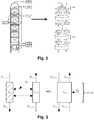
- FIG. 2 A construction of a distillation column on which the invention is based, with several stages, such as the low-pressure column 12, for example FIG. 1 , as well as a conversion into a model with appropriate equilibrium stages is schematically in FIG. 2 shown.
- Typical stages of a distillation column comprise a distributor, one or more stages designed as packings (or alternatively trays) and a collector.
- the distributor accepts fluid coming from above and distributes it to the (uppermost) packing distributed in the area. Conversely, gas flows from the packing up the distributor. Liquid leaking from the (bottom) packing is collected in the collector and directed downwards. Conversely, the gas coming from below is accepted by the collector and directed into the overlying packing.
- the column is supplied with air (AIR) and at least oxygen and nitrogen are taken off in gaseous form (GOX, GAN) and / or liquid (LOX, LIN). Furthermore, usually impure nitrogen (UN2) is withdrawn and, if desired, noble gases such as argon, etc.
- AIR air
- GOX, GAN gaseous form
- LOX, LIN liquid
- noble gases such as argon, etc.
- models 101 for distributors and models 102 for equilibrium stages corresponding to a package are used.
- a collector model can be integrated by adapting the hydrodynamics in the existing distribution model. The transition between two stages or between a stage and a distributor subject to flow resistances R L (liquid) and R V (gas) and conductances C L (liquid) and C V (gas).
- a model for an equilibrium stage (see FIG. 3 ), in a preferred development also for a distribution and collector system, a condenser and a sump (heated / unheated) used.
- these submodels can then be joined together to form the desired overall system.
- the calculation of the thermal separation takes place via series-connected equilibrium stages, which represent a certain height of a packing.
- the actual height of a pack that corresponds to exactly one equilibrium level is also called the HETP value (Heigth Equivalent of a Theoretical Plate).
- FIG. 3 shows how an ascending vapor stream and a falling stream of liquid exchange mass and energy. The corresponding quantities result from the assumption of equilibrium (instead of a material and heat transfer model).
- feeds and feeds of the rectification system can be realized and the cross-mixing of a packed column over the total cross section (diameter up to 5 m in the case of large plants) can be improved.
- both an empty and overflow of the distributor can be simulated closed.
- the collector model can be integrated by adapting the hydrodynamics in the existing distribution model, i. Collectors and distributors between two stages are preferably modeled together.
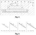
- a distributor can be interpreted as a container with different cross-sectional areas, in which liquid can accumulate, as in a Section view in FIG. 4 is shown.
- the entire column section is defined by the outer dashed line.
- the liquid flows, as indicated by the solid arrows, from above through the cross-sectional areas A 3 to A 1 , the gas flows opposite, as indicated by the dashed arrows, upwards.
- the uppermost section A 3 corresponds to the inlet channel from the overlying collector or a feed nozzle from the column wall. This opens into a larger cross-section A 2 , which distributes the liquid for the first time over the column surface. In this cross section, the liquid is mirrored in normal operation and the level fluctuates depending on the liquid load. Below this section are other channels that occupy the cross-sectional area A 1 .
- the liquid level (in A 1 and A 2 ) is narrow obliquely hatched, the gas-filled volume (remainder) is shaded obliquely.
- the modeling of the distributor is similar to the model approach of the equilibrium stage, which is why only the differences are discussed below.
- a constant value is assumed which is adapted to empirical values or measured data. This simplification is due to the low pressure loss of the slowly flowing gas phase and a constant channel geometry.
- the drag coefficient can be set approximately equal to that of an equilibrium level. No mass transport takes place in a distributor between gas and liquid phase, since the specific phase interface is smaller by about a factor of 1,500 compared to a theoretical equilibrium stage. Thus, the mass and energy conservation can not be balanced on the gross content of the entire column section, but takes place separately for the two phases.
- the concentration of the effluent gas and liquid flow is thus always equal to the concentration of the corresponding fluid content.
- the liquid volume N L of the distributor model does not exist.
- An implicit pressure determination via an adjustment of fluid content and container volume can therefore not be carried out for the liquid phase.
- this would be associated with very high gradients due to the incompressibility of liquids. Therefore, it is changed from an isochoric to an isobaric view for the liquid balance element.
- the pressure of the liquid is set equal to the pressure of the gas phase, which is located around the manifold.
- This formulation is equivalent to the outflow formula of Toricelli with superimposed pressure difference ⁇ pV by the ascending gas flow.
- N ⁇ L M ⁇ L M W .
- L ⁇ L ⁇ u 3 ⁇ A hole M W .
- L ⁇ L ⁇ 2 ⁇ G ⁇ H + 2 ⁇ ⁇ p V ⁇ L ⁇ A hole M W .
- the pressure is increased at this point by the hydrostatic pressure of the dammed liquid.
- F G F R + F D a criterion for liquid breakthrough into the underlying equilibrium level is determined.
- F G represents the weight force of the liquid molecules, which acts counter to the flow direction of the gas.
- the shear force transferred to the film by the gas is designated by F R. Due to the pressure drop of the gas flow due to friction additional acts a compressive force F D.
- determination equations are advantageously also adapted.
- the composition of the exiting gas stream from an equilibrium stage for the single-phase case is equal to the concentration of the fluid content in the balance element. If the rectification effect occurs when two-phase conditions occur, the low-boiling components accumulate in the gas phase and the separation of substances is based on the isofugacity condition.
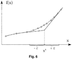
- f (x) could describe the dependence of the density on the enthalpy. In the superheated (gaseous state) this is continuously differentiable, but at the boiling point, where the first liquid molecules form, a kink on because the vapor content depends discontinuously on the enthalpy.
- the range with deviations from the original function is called regularization interval and is in FIG. 5 denoted by ⁇ .
- This model approach allows for a simplified initialization strategy over time as a homotopy parameter.
- the system can be initialized with a static gas cushion.
- the onset of fluid movement and the material separation occurring are in accordance with the conditions of Feed streams. This is advantageous above all for the determination of a stationary solution of a coupled double column system, since no concentration profiles have to be estimated in advance.
- a regularization function is advantageously used, which allows a continuously differentiable transition.
- the concept of the generalized vapor fraction has proved to be particularly robust, which is explained in the following according to Thomas [125]:
- vf gen assumes values greater than 1 for a superheated, gaseous and less than 0 for a single phase, supercooled stream.
- the simplest function with which the parameter ⁇ can be determined is a straight line equation.
- the following regularizations may preferably be used for the equilibrium stage and the distribution system.
- phase separation based on the isofugacity condition is always calculated independently of the current state of the gross content in the balance element. Even in the overheated state, virtual compositions are determined from extrapolated fugacity coefficients that have no physical significance. Therefore, the composition of the outflowing gas phase in the single-phase case must be blended from the equilibrium concentrations to the concentration of the bulk phase.
- the deviation from the original function can be set by selecting parameter B 2 . The larger this value, the smaller the absolute deviation.
Landscapes
- Engineering & Computer Science (AREA)
- Physics & Mathematics (AREA)
- General Engineering & Computer Science (AREA)
- Mechanical Engineering (AREA)
- Thermal Sciences (AREA)
- Theoretical Computer Science (AREA)
- General Physics & Mathematics (AREA)
- Emergency Medicine (AREA)
- Health & Medical Sciences (AREA)
- Manufacturing & Machinery (AREA)
- Chemical Kinetics & Catalysis (AREA)
- Chemical & Material Sciences (AREA)
- Geometry (AREA)
- Evolutionary Computation (AREA)
- Computer Hardware Design (AREA)
- Quality & Reliability (AREA)
- Automation & Control Theory (AREA)
- Separation By Low-Temperature Treatments (AREA)
Abstract
Description
- Die Erfindung betrifft ein Verfahren zum Bestimmen eines Zustands einer Destillationskolonne mit mehreren Kolonnenstufen zur Zerlegung eines Einsatzfluidstroms in einzelne Fluidkomponenten.
- Ein typischer Vertreter der Zerlegung eines Einsatzfluidstroms in einzelne Fluidkomponenten ist die Luftzerlegung. Die Herstellung von Luftprodukten in flüssigem oder gasförmigem Zustand durch Tieftemperaturzerlegung von Luft in (kryogenen) Luftzerlegungsanlagen (engl. air separation unit, ASU) ist bekannt und beispielsweise bei H.-W. Häring (Hrsg.), Industrial Gases Processing, Wiley-VCH, 2006, insbesondere Abschnitt 2.2.5, "Cryogenic Rectification", beschrieben.
- Luftzerlegungsanlagen weisen Destillationssäulensysteme auf, die beispielsweise als Zweisäulensysteme, insbesondere als klassische Linde-Doppelsäulensysteme, aber auch als Drei- oder Mehrsäulensysteme ausgebildet sein können. Neben den Destillationssäulen zur Gewinnung von Stickstoff und/oder Sauerstoff in flüssigem und/oder gasförmigem Zustand (beispielsweise flüssigem Sauerstoff, LOX, gasförmigem Sauerstoff, GOX, flüssigem Stickstoff, LIN und/oder gasförmigem Stickstoff, GAN), also den Destillationssäulen zur Stickstoff-Sauerstoff-Trennung, können Destillationssäulen zur Gewinnung weiterer Luftkomponenten, insbesondere der Edelgase Krypton, Xenon und/oder Argon, vorgesehen sein. Destillationssäulen werden auch als Destillationskolonnen bezeichnet.
- Luftzerlegungsanlagen werden üblicherweise statisch (oder allenfalls mit einer sehr geringen Dynamik) betrieben. Dabei wird ein Einsatzluftstrom mittels eines Hauptluftverdichters angesaugt und verdichtet. Die Verdichterleistung wird üblicherweise konstant auf dem Betriebspunkt gehalten, für den die Anlage ausgelegt ist.
- Seliger et al.: "Modelling and dynamics of an air separation rectification column as part of an IGCC power plant", Separation and Purification Technology 49 (2006), Seiten 136-148, Elsevier Science, Amsterdam, beschreibt die Modellierung einer Destillationssäule in einem stationären Zustand.
- Ausgehend von diesem Stand der Technik wird ein Verfahren zum Bestimmen eines Zustands einer Destillationskolonne mit mehreren Kolonnenstufen zur Zerlegung eines Einsatzfluidstroms in einzelne Fluidkomponenten mit den Merkmalen des Patentanspruchs 1 vorgeschlagen. Vorteilhafte Ausführungsformen sind jeweils Gegenstand der Unteransprüche sowie der nachfolgenden Beschreibung.
- Ein Aspekt der Erfindung betrifft ein solches Verfahren, dem ein neuartiges Modell einer Destillationskolonne zugrunde liegt, wobei der Zustand in Abhängigkeit von zwischen benachbarten Kolonnenstufen herrschenden Drücken bestimmt wird. Ein auf diese Weise bestimmter Zustand ist insbesondere charakterisiert durch eine Temperatur und/oder Fluidkomponentenkonzentrationen für jede Kolonnenstufe, welche somit vorzugsweise ebenfalls berücksichtigt werden.
- Die Erfindung ermöglicht, eine Destillationskolonne und damit insbesondere eine Luft- bzw. allgemein Fluidzerlegungsanlage in einem dynamischen Zustand, d.h. insbesondere während des Verschwindens oder Entstehens einer gasförmigen oder flüssigen Strömung, zu simulieren und basierend auf den Ergebnissen dann insgesamt nicht mehr nur statisch, sondern dynamisch z.B. mit variabler Verdichterleistung zu betreiben. Dadurch kann insbesondere auf variierenden Bedarf und auf schwankende Energiepreise (auch für Regelenergie, d.h. die Energie, die ein Netzbetreiber benötigt, um unvorhergesehene Leistungsschwankungen in seinem Stromnetz auszugleichen) als Beispiele für Kostengrößen gezielt reagiert werden.
- Beispielsweise schwanken mittlerweile Energiepreise über die Zeit teilweise sehr stark, so dass der statische Betrieb von Fluidzerlegungsanlagen aus wirtschaftlicher Sicht nicht mehr optimal ist. Jedoch waren bisher keine Methoden bekannt, um das Verhalten der Anlage bei einem schwankenden und dabei insbesondere einem ganz ausbleibenden bzw. neu einsetzenden Einsatzfluidstrom genau genug vorhersagen zu können. Insbesondere stellen sich Fragen nach der Betreibbarkeit, einer maximalen Lastwechselgeschwindigkeit, Auswirkungen auf die Lebensdauer der Anlage, einer optimalen Steuerung und einem Einfluss auf die Produktqualität.
- Eine wesentliche Komponente für die Dynamik einer Fluidzerlegungsanlage sind die Destillationskolonnen. Diese Apparate stellen nicht nur Speicher für Masse und Energie dar (welche durch Verzögerungsglieder gut abzubilden sind), sondern zeigen ein hochgradig nichtlineares Zusammenspiel von Temperatur-, Konzentrations-, Druck- und Belastungsprofilen mit dem (über die Kolonnenhöhe verteilten) Speichervolumen. Um dieses Verhalten simulationstechnisch abzubilden, ist eine Reihe von Herausforderungen zu bewältigen:
- Die Initialisierung / Startwertrechnung einer Kolonne ist schon im einfacheren Falle des stationären Kolonnenmodells schwierig.
- Die Gleichungen für das Phasengleichgewicht (Isofugazitätsgleichungen) müssen bzgl. des Verschwindens einer Phase stabilisiert werden.
- Die Gleichungen für das hydrostatische Ablaufen (1D-Impulsbilanzen) müssen ebenfalls bzgl. des "Trockenlaufens" stabilisiert werden.
- Ströme innerhalb des Anlagenmodells müssen bei extremen Betriebsfällen zu Null werden oder auch die Strömungsrichtung wechseln.
- Die Erfindung bedient sich dazu eines neuen Ansatzes für die Modellierung einer Destillationskolonne mit mehreren Kolonnenstufen auf Basis einer rigorosen dynamischen thermohydraulischen Simulation einer Destillationskolonne mit Berücksichtigung zeitvariabler Parameter. Dabei werden die einzelnen Kolonnenstufen (üblicherweise sog. Packungen oder Böden) als Gleichgewichtsstufen modelliert. Es handelt sich um einen gleichungsbasierten Simulationsansatz, bei dem die Lösung der Modellgleichungen simultan mit einem adaptierten Newton-Verfahren (siehe z.B. Hanke-Bourgeois, Martin: Grundlagen der numerischen Mathematik und des wissenschaftlichen Rechnens. Studium. Vieweg + Teubner, Wiesbaden, 3., aktualisierte Auflage, 2009) erfolgt. Zur Bestimmung der zeitlichen Änderung der Betriebsbedingungen bzw. des Zustands wird vorzugsweise ein Rückwärtsdifferenzen-Verfahren mit einer Prädiktor-Korrektor-Methode angewandt, bei der zuerst eine Näherungslösung des Gleichungssystems für den Zeitschritt n+1 erzeugt wird (vgl. BDF-Verfahren (englisch Backward Differentiation Formulas)). Die Näherungslösung kann über ein Polynom ermittelt werden, dessen Koeffizienten aus dem aktuellen Zeitschritt n und dem vorherigen Zeitschritt n-1 gewonnen werden. Die Bestimmung von Schätzwerten der zeitlich variablen Prozessgrößen erfolgt für den Zeitschritt n+1 folglich durch Extrapolation der Polynomfunktion. Mit diesen extrapolierten Startwerten wird in einem zweiten Schritt die exakte Korrektur der Lösung über das oben genannte Newton-Verfahren durchgeführt. Es sei der Vollständigkeit halber erwähnt, dass auch andere Integrationsverfahren verwendet werden können. Eine dynamische Optimierung des Kolonnenbetriebs könnte z.B. auch mit einem Kollokationsverfahren durchgeführt werden.
- Im Gegensatz zur klassischen Verfahrenstechnik werden dabei jedoch im Modell alle - sowohl gasförmigen als auch flüssigen - Fluidbewegungen durch eine treibende Totaldruckdifferenz hervorgerufen. Bei diesem, als druckgetrieben bezeichneten Ansatz werden alle Strömungswege über Widerstandsbeiwerte R und Leitwerte C charakterisiert. Vorteilhafterweise bedient sich die Erfindung dabei einer neuartigen Herangehensweise, bei der ein quasi-linearer Ansatz der Form

- Ein weiterer Aspekt der Erfindung betrifft ein Verfahren zum Betreiben einer Destillationskolonne, insbesondere als Teil einer Fluidzerlegungsanlage, bei dem anhand des obigen Modells der Destillationskolonne für wenigstens eine Stellgröße, wie z.B. eine Einsatzfluidstromdurchflussrate oder Verdichterleistung, ein einzustellender Stellgrößenwert in Abhängigkeit von wenigstens einer Regelgröße ermittelt und eingestellt wird. Bei der Regelgröße kann es sich insbesondere um eine Produktqualität, einen Produktvolumen-oder-massenstrom handeln.
- Dabei handelt es sich im Prinzip um eine sog. modellprädiktive Regelung (engl. modell predictive control, MPC). Bei der MPC wird ein zeitdiskretes dynamisches Modell des zu regelnden Prozesses verwendet, um das zukünftige Verhalten des Prozesses in Abhängigkeit von den Eingangssignalen zu berechnen. Dies ermöglicht die Berechnung von - im Sinne einer Gütefunktion - optimalen Eingangssignalen, die zu optimalen Ausgangssignalen führen. Dabei können gleichzeitig Eingangs-, Ausgangs- und Zustandsbeschränkungen berücksichtigt werden. Wie nachfolgend erläutert wird, kann es sich bei der Regelgröße insbesondere auch um eine Kostengröße handeln.
- Eine Weiterbildung dieses Aspekts betrifft ein Verfahren zum Betreiben einer Destillationskolonne, insbesondere als Teil einer Fluidzerlegungsanlage, bei dem eine Durchflussrate, insbesondere eine Volumendurchflussrate, des Einsatzfluidstroms, insbesondere mittels Ansteuerung einer Verdichtereinheit, in Abhängigkeit von wenigstens einer Kostengröße vorgegeben wird. Als Kostengröße sind insbesondere ein Energiebedarf, ein Produktbedarf, eine Produktqualität, eine Eduktverfügbarkeit, eine Anlagenbelastung bzw. - Lebensdauer usw. zu verstehen, d.h. Größen, auf die hin der Betrieb der Anlage optimiert werden soll (der Wert der Größe soll z.B. eine gewisse Schwelle nicht über- oder unterschreiten und/oder möglichst groß oder möglichst klein werden). Insbesondere sollen auch mehrere solcher Randbedingungen gleichzeitig eingehalten werden, so dass eine Mehrgrößenregelung bzw. -optimierung vorliegt.
- Eine erfindungsgemäße Recheneinheit ist, insbesondere programmtechnisch, dazu eingerichtet, ein erfindungsgemäßes Verfahren durchzuführen.
- Auch die Implementierung des Verfahrens in Form eines Computerprogramms ist vorteilhaft, da dies besonders geringe Kosten verursacht, insbesondere wenn ein ausführendes Steuergerät noch für weitere Aufgaben genutzt wird und daher ohnehin vorhanden ist. Geeignete Datenträger zur Bereitstellung des Computerprogramms sind insbesondere magnetische, optische und elektrische Speicher, wie z.B. Festplatten, Flash-Speicher, EEPROMs, DVDs u.a.m. Auch ein Download eines Programms über Computernetze (Internet, Intranet usw.) ist möglich.
- Weitere Vorteile und Ausgestaltungen der Erfindung ergeben sich aus der Beschreibung und der beiliegenden Zeichnung.
- Die Erfindung ist anhand von Ausführungsbeispielen in der Zeichnung schematisch dargestellt und wird im Folgenden unter Bezugnahme auf die Zeichnung beschrieben.
- Kurze Beschreibung der Zeichnungen
-
Figur 1 zeigt schematisch in einem Blockdiagramm eine Luftzerlegungsanlage mit Destillationskolonnen, wie sie der Erfindung zugrunde liegen kann. -
Figur 2 zeigt schematisch eine Überführung einer Destillationskolonne bzw. -säule mit mehreren Stufen in ein Modell mit entsprechenden Gleichgewichtsstufen. -
Figur 3 zeigt schematisch das Modell einer einzelnen Gleichgewichtsstufe; links: getrennter Bilanzraum; rechts: zusammengefasstes Bilanzvolumen. -
Figur 4 zeigt schematisch einen Verteiler in einem Kolonnenabschnitt. -
Figur 5 zeigt die vier möglichen Strömungszustände in einer Stufe:- links: reine Gasströmung,
- halb links: Flüssigkeitsansammlung,
- halb rechts: Flüssigkeitsdurchbruch,
- rechts: stationäre Strömung.
-
Figur 6 veranschaulicht eine Regularisierung anhand des Verhaltens eines Rückwärtsdifferenzenverfahrens. - Die der Erfindung zugrunde liegende Trennung von Fluidkomponenten, wie z.B. die Gewinnung von Sauerstoff, Stickstoff und gewünschtenfalls weiteren Stoffen, wie z.B. Argon, erfolgt in einer Fluidzerlegungsanlage, wie z.B. einer herkömmlichen Luftzerlegungsanlage, wie beispielsweise in
Figur 1 gezeigt. Hierbei wird der Ausgangsstoff Luft abgekühlt und in ein Rektifikationssystem aufweisend ein Kolonnensystem geleitet, das eine ausreichend große Stoffaustauschfläche zur Verfügung stellt. - Luftzerlegungsanlagen der gezeigten Art sind vielfach an anderer Stelle beschrieben, beispielsweise bei H.-W. Häring (Hrsg.), Industrial Gases Processing, Wiley-VCH, 2006, insbesondere Abschnitt 2.2.5, "Cryogenic Rectification". Für detaillierte Erläuterungen zu Aufbau und Funktionsweise sei daher auf entsprechende Fachliteratur verwiesen. Eine Luftzerlegungsanlage zum Einsatz der vorliegenden Erfindung kann auf unterschiedlichste Weise ausgebildet sein.
- Die in
Figur 1 beispielhaft gezeigte Luftzerlegungsanlage verfügt unter anderem über einen Hauptluftverdichter 1, eine Vorkühleinrichtung 2, ein Reinigungssystem 3, eine Nachverdichteranordnung 4, einen Hauptwärmetauscher 5, eine Entspannungsturbine 6, eine Drosseleinrichtung 7, eine Pumpe 8 und ein Destillationssäulensystem 10. Das Destillationssäulensystem 10 umfasst im dargestellten Beispiel eine klassische Doppelsäulenanordnung aus einer Hochdrucksäule 11 und einer Niederdrucksäule 12 sowie eine Rohargonsäule 13 und eine Reinargonsäule 14. - In der Luftzerlegungsanlage 100 wird ein Einsatzluftstrom mittels des Hauptluftverdichters 1 über ein nicht bezeichnetes Filter angesaugt und verdichtet. Der verdichtete Einsatzluftstrom wird der mit Kühlwasser betriebenen Vorkühleinrichtung 2 zugeführt. Der vorgekühlte Einsatzluftstrom wird in dem Reinigungssystem 3 aufgereinigt. In dem Reinigungssystem 3, das typischerweise ein Paar von im Wechselbetrieb eingesetzten Adsorberbehältern umfasst, wird der vorgekühlte Einsatzluftstrom weitgehend von Wasser und Kohlendioxid befreit.
- Stromab des Reinigungssystems 3 wird der Einsatzluftstrom in zwei Teilströme aufgeteilt. Einer der Teilströme wird auf dem Druckniveau des Einsatzluftstroms in dem Hauptwärmetauscher 5 vollständig abgekühlt. Der andere Teilstrom wird in der Nachverdichteranordnung 4 nachverdichtet und ebenfalls in dem Hauptwärmetauscher 5 abgekühlt, jedoch nur auf ein Zwischentemperaturniveau. Dieser sogenannte Turbinenstrom wird nach der Abkühlung auf das Zwischentemperaturniveau mittels der Entspannungsturbine 6 auf das Druckniveau des vollständig abgekühlten Teilstroms entspannt, mit diesem vereinigt, und in die Hochdrucksäule 11 eingespeist.
- In der Hochdrucksäule 11 werden eine sauerstoffangereicherte flüssige Sumpffraktion sowie eine stickstoffangereicherte gasförmige Kopffraktion gebildet. Die sauerstoffangereicherte flüssige Sumpffraktion wird aus der Hochdrucksäule 11 abgezogen, teilweise als Heizmedium in einem Sumpfverdampfer der Reinargonsäule 14 verwendet und jeweils in definierten Anteilen in einen Kopfkondensator der Reinargonsäule 14, einen Kopfkondensator der Rohargonsäule 13 sowie die Niederdrucksäule 12 eingespeist. In den Verdampfungsräumen der Kopfkondensatoren der Rohargonsäule 13 und der Reinargonsäule 14 verdampfendes Fluid wird ebenfalls in die Niederdrucksäule 12 überführt.
- Vom Kopf der Hochdrucksäule 11 wird das gasförmige stickstoffreiche Kopfprodukt abgezogen, in einem Hauptkondensator, der eine wärmetauschende Verbindung zwischen der Hochdrucksäule 11 und der Niederdrucksäule 12 herstellt, verflüssigt, und in Anteilen als Rücklauf auf die Hochdrucksäule 11 aufgegeben und in die Niederdrucksäule 12 entspannt.
- In der Niederdrucksäule 12 werden eine sauerstoffreiche flüssige Sumpffraktion sowie eine stickstoffreiche gasförmige Kopffraktion gebildet. Erstere wird teilweise in der Pumpe 8 flüssig auf Druck gebracht, in dem Hauptwärmetauscher 5 erwärmt, und als Produkt bereitgestellt. Aus einer Flüssigkeitsrückhalteeinrichtung am Kopf der Niederdrucksäule 12 wird ein flüssiger stickstoffreicher Strom abgezogen und als Flüssigstickstoffprodukt aus der Luftzerlegungsanlage 100 ausgeführt werden. Ein vom Kopf der Niederdrucksäule 12 abgezogener gasförmiger stickstoffreicher Strom wird durch den Hauptwärmetauscher 5 geführt und als Stickstoffprodukt auf dem Druck der Niederdrucksäule 12 bereitgestellt. Aus der Niederdrucksäule 12 wird ferner ein Strom aus einem oberen Bereich abgezogen und nach Erwärmung in dem Hauptwärmetauscher 5 als sogenannter Unreinstickstoff in der Vorkühleinrichtung 2 bzw. nach einer Aufheizung mittels eines elektrischen Heizers in dem Reinigungssystem 3 verwendet.
- Ein Aufbau einer beispielsweise der Erfindung zugrunde liegenden Destillationskolonne mit mehreren Stufen, wie z.B. der Niederdrucksäule 12 aus
Figur 1 , sowie eine Überführung in ein Modell mit entsprechenden Gleichgewichtsstufen ist schematisch inFigur 2 dargestellt. Übliche Stufen einer Destillationskolonne weisen einen Verteiler, ein oder mehrere hier als Packungen (oder alternativ Böden) ausgebildete Stufen und einen Sammler auf. Der Verteiler nimmt von oben kommende Flüssigkeit entgegen und führt diese in der Fläche verteilt der (obersten) Packung zu. Umgekehrt strömt Gas aus der Packung über den Verteiler nach oben. Aus der (untersten) Packung austretende Flüssigkeit wird im Sammler gesammelt und nach unten geleitet. Umgekehrt wird das von unten kommende Gas durch den Sammler entgegengenommen und in die darüberliegende Packung geleitet. - Insgesamt wird der Kolonne Luft (AIR) zugeführt und zumindest Sauerstoff und Stickstoff jeweils gasförmig (GOX, GAN) und/oder flüssig (LOX, LIN) entnommen. Weiterhin wird üblicherweise Unreinstickstoff (UN2) abgezogen und gewünschtenfalls Edelgase wie Argon usw.
- Bei der Übertragung einer solchen Destillationssäule in ein Modell werden gemäß einer bevorzugten Ausführungsform der Erfindung Modelle 101 für Verteiler und Modelle 102 für Gleichgewichtsstufen, welche einer Packung entsprechen, verwendet. Dabei kann auch ein Sammlermodell durch Adaption der Hydrodynamik in das bestehende Verteilermodell integriert werden. Der Übergang zwischen zwei Stufen bzw. zwischen einer Stufe und einem Verteiler unterliegt dabei Strömungswiderständen RL (Flüssigkeit) und RV (Gas) sowie Leitwerten CL (Flüssigkeit) und CV (Gas).
- Es sei darauf hingewiesen, dass als Index L für die flüssige Phase, V für die Gasphase, n für die jeweilige Stufe und j für die jeweilige Luftkomponente verwendet werden.
- Gemäß dem Kolonnensystem wird ein Modell für eine Gleichgewichtsstufe (siehe
Figur 3 ), in bevorzugter Weiterbildung auch für ein Verteiler- und Sammlersystem, einen Kondensator sowie einen Sumpf (beheizt/unbeheizt) verwendet. Durch einen hierarchischen Modellierungsansatz können diese Teilmodelle anschließend zum gewünschten Gesamtsystem zusammengefügt werden. Die Berechnung der thermischen Stofftrennung erfolgt über hintereinander geschaltete Gleichgewichtsstufen, die eine bestimmte Höhe einer Packung repräsentieren. Die tatsächliche Höhe einer Packung, die genau einer Gleichgewichtsstufe entspricht wird auch HETP-Wert (Heigth Equivalent of a Theoretical Plate) genannt. - Es wird sowohl stoffliches, thermisches als auch mechanisches Gleichgewicht der in der Stufe auftretenden Gas- und Flüssigkeitsströme angenommen. Zur Modellierung der Strömungsvorgänge wird eine instationäre Massen- und Energieerhaltung verwendet. Eine Impulserhaltung wird vorzugsweise quasistationär modelliert. Insgesamt gibt es somit vorzugsweise Speicherterme für Masse und Energie, nicht aber für den Impuls. Impulswellen, also Schallwellen, sind auf einer kleineren Zeitskala und nur in Ausnahmefällen relevant (beispielsweise bei Abschätzung eines Staudrucks).
- Das jeder einzelnen der Gleichgewichtsstufen 202 zugrunde liegende Modell ist rechts in
Figur 3 gezeigt. Links wird eine konventionelle Modellierung mit getrennten Bilanzvolumina für Gas- (N V,n ) und Flüssigphase (NL,n ) und rechts der verwendete Ansatz mit einem Bilanzvolumen NZ,n . Ṅ beschreibt den Molenstrom über die Systemgrenze.Figur 3 zeigt, wie ein aufsteigender Dampfstrom und ein herabrinnender Flüssigkeitsstrom Masse und Energie austauschen. Die entsprechenden Mengen ergeben sich dabei durch die Annahme des Gleichgewichts (statt eines Stoff- und Wärmeübergangsmodells). - Die zeitliche Änderung der Gesamtstoffmenge NZ,n entspricht der Summe der zuströmenden und abströmenden Anteile gemäß:

- Aus der Energieerhaltung folgt, dass sich eine Energieänderung aus einem Wärmestrom, einem technischen Arbeitsstrom und einem zuströmenden und abströmenden Massenstrom zusammensetzt:

- E: Energie
- Q: Wärme
- Lt : technische Arbeit
- zu , weg : zuströmende bzw. wegströmende Anteile
- Ṅ: Molenstrom
- MW : Molgewicht
- v: Geschwindigkeit
- h: partielle molare Enthalpie
- g: Erdbeschleunigung
- z: Höhe
- Hierbei können die kinetischen Beiträge v 2/2 üblicherweise vernachlässigt werden.
- Aus der Impulserhaltung folgt:

- P : Gesamtimpuls
- ρu : Impulsdichte
- F i : angreifende Kraft (z.B. Schwerkraft)
- i: Laufindex
- Der Gleichgewichtszustand beinhaltet dabei insbesondere für jede Stufe n ein thermisches Gleichgewicht zwischen Gas und Flüssigkeit, Tn,L = Tn,V , d.h. beide Phasen haben dieselbe Temperatur, ein stoffliches Gleichgewicht, f"n,j = f'n,j , d.h. die Fugazität einer Komponente j ist in allen vorliegenden Phasen (f' flüssig und f" gasförmig) gleich, und ein mechanisches Gleichgewicht, C · Δp = R · Ṅ, d.h. der Druckunterschied für eine Phase zwischen zwei benachbarten Stufen entspricht dem Produkt aus Strömungswiderstand und Stoffmengenstrom. Für jede Stufe ist dabei die Randbedingung einzuhalten, dass die Summe der Volumina aus Gas Vn,V und Flüssigkeit Vn,L dem Volumen der Stufe Vn entspricht, Vn,L + Vn,V = Vn .
- Anhand der aktuellen Fluidbelastung ergibt sich ein bestimmter Druckverlust und Flüssigkeitsinhalt im System, der über Auslegungskorrelationen, wie z.B. von Kooijman, H.A., K.R. Krishnamurty und M.W. Biddulph: A NEW PRESSURE DROP MODEL FOR STRUCTURED PACKING: 634th Event of the European Federation of Chemical Engineering. GVC - VDI-Society of Chemical and Process Engineering, Germany, 2002, beschrieben, bestimmt wird. Diese berücksichtigen vorteilhafterweise auch das Stauen von Flüssigkeit an den Stoßstellen der Packungslagen bei höheren Kolonnenbelastungen. Zusätzlich ergibt sich daraus der mitbilanzierte gasförmige Fluidinhalt über die Differenz zwischen Kolonnen- und Flüssigkeitsvolumen. Über ein Verteiler- und Sammlersystem können Zu- und Abspeisungen des Rektifikationssystems realisiert sowie die Quervermischung einer Packungskolonne über den Gesamtquerschnitt (Durchmesser bis zu 5m bei Großanlagen) verbessert werden. Mit dem erfindungsgemäßen Modell kann sowohl ein Leer- als auch Überlaufen des Verteilers geschlossen simuliert werden.
- Flüssigkeitsinhalt und damit thermische Trägheit befindet sich akkumuliert in jedem Verteiler und Sammlersystem, das oberhalb und unterhalb eines Packungsabschnitts verbaut wird. Diese Einbauten sind notwendig, um die abfließende Flüssigkeit zu sammeln, zu mischen und erneut gleichmäßig auf den darunterliegenden Packungsabschnitt zu verteilen. Dabei kann das Sammlermodell durch Adaption der Hydrodynamik in das bestehende Verteilermodell integriert werden, d.h. Sammler und Verteiler zwischen zwei Stufen werden vorzugsweise gemeinsam modelliert.
- Interpretiert werden kann ein Verteiler als ein Behälter mit unterschiedlichen Querschnittsflächen, in denen sich Flüssigkeit aufstauen kann, wie er in einer Schnittansicht in
Figur 4 gezeigt ist. Der gesamte Kolonnenabschnitt ist durch die äußere gestrichelte Linie definiert. Die Flüssigkeit läuft, wie mit den durchgezogenen Pfeilen gekennzeichnet, von oben durch die Querschnittsflächen A 3 bis A 1, das Gas strömt entgegengesetzt, wie mit den gestrichelten Pfeilen gekennzeichnet, nach oben. - Der oberste Querschnitt A 3 entspricht dem Zulaufkanal aus dem darüberliegenden Sammler oder einem Zuspeisestutzen aus der Kolonnenwand. Dieser mündet in einen größeren Querschnitt A 2, der die Flüssigkeit ein erstes Mal über die Kolonnenfläche verteilt. In diesem Querschnitt ist die Flüssigkeit im normalen Betrieb frei gespiegelt und der Füllstand schwankt je nach Flüssigkeitsbelastung. Unter diesem Abschnitt befinden sich weitere Kanäle, die die Querschnittsfläche A 1 einnehmen.
- An der Unterseite dieser Flächen sind kleinere Bohrungen angebracht, die für eine definierte Aufgabe der Flüssigkeit auf die darunterliegende Packung sorgen. Diese Bohrungen stellen eine Einschnürung der Flüssigkeitsströmung dar. Die entgegenströmende Gasphase wird durch die Querschnittsfläche A 1 verengt, um anschließend wieder über den gesamten Kolonnenquerschnitt in die darüberliegende Packungslage einzutreten, weshalb ein Druckverlust entsteht.
- Der Flüssigkeitsstand (in A1 und A2) ist eng schräg schraffiert, das von Gas erfüllte Volumen (Rest) ist weit schräg schraffiert.
- Prinzipiell erfolgt die Modellierung des Verteilers ähnlich zum Modellansatz der Gleichgewichtsstufe, weshalb nachfolgend nur auf die Unterschiede eingegangen wird. Für den Widerstandsbeiwert der Gasphase wird ein konstanter Wert angenommen, der an Erfahrungswerte oder Messdaten angepasst wird. Diese Vereinfachung wird aufgrund des geringen Druckverlustes der langsam strömenden Gasphase und einer konstanten Kanalgeometrie getroffen. Als Anhaltswert kann der Widerstandsbeiwert in etwa gleich dem einer Gleichgewichtsstufe gesetzt werden. Zwischen Gas- und Flüssigphase findet in einem Verteiler kein Stofftransport statt, da die spezifische Phasengrenzfläche im Vergleich zu einer theoretischen Gleichgewichtsstufe in etwa um den Faktor 1.500 kleiner ist. Somit kann auch die Massen- und Energieerhaltung nicht über den Bruttoinhalt des gesamten Kolonnenabschnitts bilanziert werden, sondern erfolgt getrennt für die beiden Phasen.
- Die Konzentration des abfließenden Gas- und Flüssigkeitsstroms ist dadurch immer gleich der Konzentration des entsprechenden Fluidinhalts. Im Gegensatz zur Gleichgewichtsstufe entsteht durch die geänderte Wahl der Bilanzierung folgender Sachverhalt:
Bei einem Anfahrvorgang aus dem warmen, trockenen Zustand ist das Flüssigvolumen NL des Verteilermodells nicht vorhanden. Eine implizite Druckbestimmung über einen Abgleich von Fluidinhalt- und Behältervolumen kann für die Flüssigphase daher nicht erfolgen. Darüber hinaus wäre dies mit sehr hohen Gradienten durch die Inkompressibilität von Flüssigkeiten verbunden. Daher wird für das flüssige Bilanzelement von einer isochoren auf eine isobare Betrachtung gewechselt. Der Druck der Flüssigkeit wird gleich dem Druck der Gasphase gesetzt, die sich um den Verteiler befindet. - Bei ansteigender Flüssigkeitsmenge verdrängt das Flüssigkeitsvolumen einen Teil des Gaspolsters und nimmt einen immer größeren Volumenanteil ein. Durch die variierende Bilanzgröße des Flüssigkeitselements muss zusätzlich technische Arbeit in Form von Volumenänderungsarbeit geleistet werden, die nach Stephan et al.: Thermodynamik. Springer Berlin Heidelberg, Berlin, Heidelberg, 2013. über dLt = -p · dV
berechnet wird. Diese Arbeit wird je nach Volumenänderung von einem Bilanzelement geleistet und gleichzeitig vom anderen aufgenommen, da beide den gleichen Druck aufweisen. Die Änderung des Flüssigkeitsvolumens ist von dem aktuellen Füllstand im Verteiler abhängig und es gilt
- Für die Flüssigkeitsströmung ergibt sich aufgrund des Aufstauens im Behälter ein anderer Zusammenhang für die Hydrodynamik. Unter Vernachlässigung von Reibungskräften für die Flüssigphase in x3-Richtung aus
Figur 4 ergibt sich:
- Die Reibung an der Phasengrenzfläche wird nicht berücksichtigt, da es zu keinem entgegengesetzten Strömen von Gas- und Flüssigphase kommt und diese durch die Metallwand des Verteilers getrennt sind. Ebenso kann die innere Fluidreibung aufgrund des Aufstauens der Flüssigkeit und der verringerten mittleren Geschwindigkeit vernachlässigt werden.
- Integriert man obige Gleichung in x3-Richtung von der ruhenden Oberfläche der Höhe H bis zum Ausströmquerschnitt an der Unterseite, so ergibt sich

- Für die Strömungsgeschwindigkeit im abfließenden Querschnitt A Loch folgt daraus:

- Diese Formulierung ist gleichbedeutend mit der Ausflussformel von Toricelli bei überlagerter Druckdifferenz ΔpV durch die aufsteigende Gasströmung.
- Für die abfließende Menge aus dem Verteiler folgt

- Mit dem Ansatz der druckgetriebenen Strömung ergibt sich der Widerstandsbeiwert der Flüssigkeit über:

- Der Druck wird an dieser Stelle durch den hydrostatischen Druck der aufgestauten Flüssigkeit erhöht.
- Der zur Stofftrennung notwendige Flüssigkeitsrücklauf wird über einen Kondensator am Kopf der Kolonne durch Abfuhr von Wärme bereitgestellt. Im Sumpf des Systems befindet sich aufgestaute Flüssigkeit, die durch Wärmezufuhr verdampft werden kann und so einen aufsteigenden Gasstrom erzeugt. Modellierungen für Kondensator und Sumpf sind im Stand der Technik bekannt.
- Bedingt durch Anreize der Energiemärkte ist es erwünscht, auch ein komplettes Abschalten des Rektifikationssystems zu betrachten. Problematisch für dieses Szenario ist die Verwendung von stationär bestimmten Auslegungskorrelationen für einen dynamischen Anlaufvorgang. Bei einem warmen Anfahr- oder kalten Wiederanfahrvorgang, der schematisch in
Figur 4 dargestellt ist, strömt zuerst eine rein gasförmige Strömung durch das Rektifikationssystem. Hierbei tritt noch keine Konzentrationsänderung über der Kolonnenhöhe auf. (Das Konzentrationsprofil stellt sich im zweiphasigen Betrieb analog zum Temperaturprofil ein. Die Kolonne ist unten warm und oben kalt, für das Konzentrationsprofil reichert sich der Leichtsieder (tiefster Siedepunkt) am Kopf und der Schwersieder im Sumpf an). Bildet sich Flüssigkeit in einer Gleichgewichtsstufe, so akkumuliert sich diese zuerst, bevor sie in die darunterliegende Stufe abfließt und sich anschließend ein stationärer Betrieb einstellt. - Um diesen Vorgang und damit ein belastungsabhängiges Abfließen von Flüssigkeit zu simulieren, wird das Kräftegleichgewicht an einem Fluidfilm betrachtet. Gemäß der Bedingung

- Um den Betriebsbereich einer einphasigen Gasströmung bis hin zur zweiphasigen Rektifikation mit einem Modell abbilden zu können, werden vorteilhafterweise auch Bestimmungsgleichungen angepasst. So ist z.B. die Zusammensetzung des austretenden Gasstroms aus einer Gleichgewichtsstufe für den einphasigen Fall gleich der Konzentration des Fluidinhalts im Bilanzelement. Setzt die Rektifikationswirkung bei auftretender Zweiphasigkeit ein, so reichert sich der Leichtsieder in der Gasphase an und es gilt die Stofftrennung anhand der Isofugazitätsbedingung.
- Um das numerische Verhalten des Integrators bei diesen Schaltungen zu verbessern, werden vorzugsweise alle Unstetigkeiten im Modell regularisiert. Zur Illustration sei auf
Figur 5 verwiesen, wo mit einer durchgezogenen Linie ein Funktionsverlauf f(x) mit einer Knickstelle bei x' gezeigt ist. f(x) könnte z.B. die Abhängigkeit der Dichte von der Enthalpie beschreiben. Im überhitzten (gasförmigen Zustand) ist diese stetig differenzierbar, weist jedoch am Siedepunkt, wo sich die ersten Flüssigkeitsmoleküle bilden, einen Knick auf, da der Dampfanteil unstetig von der Enthalpie abhängt. - Das Resultat einer Regularisierung ist mit Kreisen skizziert. Durch den geglätteten Funktionsverlauf treten keine Knicke auf und die Neubildung der Jakobi-Matrix an einem Schaltpunkt x' ist nicht erforderlich. Die Prädiktion ist für den nächsten Zeitschritt bei einem Wechsel von Gleichungen näher an der gesuchten Lösung.
- Der adaptierte Funktionsverlauf wird beispielsweise über einen Homotopieparameter λ gemäß

Figur 5 mit ε bezeichnet. - Beispielsweise kann gemäß einer bevorzugten Ausführungsform ein Viertel einer Sinusschwingung für die Bestimmung des Homotopieparameters verwendet werden, und es gilt:

- Durch diesen Modellansatz lässt sich eine vereinfachte Initialisierungsstrategie mit der Zeit als Homotopieparameter anwenden. Durch die Stabilisierung des Modells für Nullströmungen und den möglichen Wechsel des Aggregatzustands kann das System mit einem ruhenden Gaspolster initialisiert werden. Das Einsetzen der Fluidbewegung und die auftretende Stofftrennung stellen sich entsprechend der Bedingungen der Zuspeiseströme ein. Vorteilhaft ist dies v.a. für die Ermittlung einer stationären Lösung eines gekoppelten Doppelsäulensystems, da keine Konzentrationsprofile im Voraus geschätzt werden müssen.
- Grundsätzlich sind zur Stabilisierung des Kolonnenmodells und der Abbildbarkeit einphasiger sowie zweiphasiger Strömungsformen mehrere Anpassungen des Grundmodells zweckmäßig.
- Für jeden Wechsel der Berechnungsgleichungen wird vorteilhafterweise eine Regularisierungsfunktion verwendet, die einen stetig differenzierbaren Übergang ermöglicht. Für dieses Konzept ist es vorteilhaft, eine allgemeingültige Schaltgröße zu definieren, mit der die Überblendungsfunktionen aktiviert werden. Für die vorliegende Simulationsaufgabe hat sich das Konzept des generalisierten Dampfanteils als besonders robust herausgestellt, welches gemäß Thomas [125] nachfolgend erläutert wird: Für den Dampfanteil eines Stromvektors gilt generell


- Durch diese Formulierung nimmt vfgen Werte größer 1 für einen überhitzten, gasförmigen und kleiner 0 für einen einphasigen, unterkühlten Strom an. Dadurch kann ein bevorstehender Phasenwechsel schon vor dem eigentlichen Auftreten detektiert werden und gegebenenfalls Maßnahmen für die Stabilisierung des Modells vor dem eigentlichen Schaltpunkt aktiviert werden.
- Für das stetig differenzierbare Überblenden von Modellgleichungen unterschiedlicher Betriebszustände werden Regularisierungsfunktionen verwendet. Als Regularisierungsfunktionen werden alle Funktionen bezeichnet, mit denen der Parameter λ zwischen Null und Eins variiert werden kann. Dies führt dazu, dass ein Funktionsverlauf gemäß f(x) = (1 - λ) · f(x) x<x' + λ · f(x) x>x' abschnittsweise definiert werden kann und in einem bestimmten Bereich ineinander überblendet wird. Die einfachste Funktion, mit welcher der Parameter λ bestimmt werden kann, ist eine Geradengleichung.
- Für die Gleichgewichtsstufe und das Verteilersystem können vorzugsweise folgende Regularisierungen verwendet werden.
- Für die Gleichgewichtsstufe sind dies:
- Die Phasentrennung anhand der Isofugazitätsbedingung wird immer unabhängig vom aktuellen Zustand des Bruttoinhalts im Bilanzelement berechnet. Auch im überhitzten Zustand werden virtuelle Zusammensetzungen aus extrapolierten Fugazitätskoeffizienten bestimmt, die keine physikalische Bedeutung haben. Daher muss die Zusammensetzung der abströmenden Gasphase im einphasigen Fall von den Gleichgewichtskonzentrationen auf die Konzentration der Volumenphase überblendet werden.
- Für die Bestimmung der Zusammensetzung der aus einer Gleichgewichtsstufe abfließenden Flüssigkeit ist ebenfalls eine Fallunterscheidung zwischen trockener und aktiver Packung zu treffen. Aufgrund von hohen Gradienten bei einer Überblendung des unstetigen Verlaufs der Stoffdaten von der Gas- auf die Flüssigphase ist eine Glättung an dieser Stelle nicht zielführend
- Zur Beseitigung von Problemen bei der Berechnung von Gradienten für eine Nullströmung wird an dieser Stelle die Übergabe der aktuellen Belastungsparameter für die Berechnung der Auslegungskorrelationen limitiert. Dadurch kann die gewählte Auslegungskorrelation für Packungen durch eine beliebige andere Korrelation ausgetauscht werden, ohne die Modellgleichungen anpassen zu müssen.
- Das oben beschriebene Verteilermodell muss sowohl für den trockenen als auch für den Betrieb mit Flüssigkeitsstand rechenbar sein. Im Vergleich zur Gleichgewichtsstufe wird die Bilanzierung der Gas- und Flüssigphase getrennt vorgenommen. Dadurch verschwindet der Flüssigkeitsinhalt für den einphasigen Fall und der Füllstand H im Verteiler ist gleich Null. Aus numerischer Sicht problematisch ist die adaptierte Ausflussbeziehung nach Toricelli mit der Steigung der Wurzelfunktion für H -> 0. Die unendliche Steigung für den Funktionswert Null führt zu einer Singularität in der Jakobi-Matrix und der gradientenbasierte Löser versagt. Abhilfe hierfür kann durch Quadrieren von u3 und Ersetzen des Quadrats der Flüssigkeitsgeschwindigkeit über

Claims (14)
- Verfahren zum Bestimmen eines Zustands einer Destillationskolonne (12) mit mehreren Kolonnenstufen zur Zerlegung eines Einsatzfluidstroms in einzelne Fluidkomponenten, wobei der Zustand in Abhängigkeit von zwischen benachbarten Kolonnenstufen herrschenden Druckunterschieden mittels eines Modells bestimmt wird,wobei im Modell sowohl die gasförmigen als auch die flüssigen Strömungen zwischen den benachbarten Kolonnenstufen von den zwischen den benachbarten Kolonnenstufen herrschenden Druckunterschieden hervorgerufen werden,wobei im Modell ein die gasförmige Strömung zwischen zwei Kolonnenstufen charakterisierender Stoffmengenstrom ṄV gegeben ist durch ṄV · RV = CV · ΔpV und ein die flüssige Strömung zwischen zwei Kolonnenstufen charakterisierender Stoffmengenstrom ṄL gegeben ist durch ṄL · RL = CL · ΔpL ,wobei, jeweils für die gasförmige oder flüssige Phase, ΔpV,L ein Totaldruckunterschied zwischen den zwei benachbarten Kolonnenstufen, RV,L ein Widerstandsbeiwert zwischen den zwei benachbarten Kolonnenstufen und CV,L ein Leitwert der Strömung zwischen den zwei benachbarten Kolonnenstufen sind.
- Verfahren nach Anspruch 1, wobei ein Zustand während eines Verschwindens oder Entstehens einer gasförmigen oder flüssigen Strömung bestimmt wird.
- Verfahren nach Anspruch 2, wobei eine Regularisierungsfunktion verwendet wird, um den Zustand zu bestimmen.
- Verfahren nach Anspruch 2 oder 3, wobei das Verschwinden oder Entstehen einer gasförmigen oder flüssigen Strömung einen Wechsel von einer Fluidbewegung auf eine Nullströmung, einen Wechsel von einer Nullströmung auf eine Fluidbewegung, einen Wechsel von einer einphasigen Gasströmung auf eine zweiphasige Rektifikation oder einen Wechsel von einer zweiphasigen Rektifikation auf eine einphasige Gasströmung umfasst.
- Verfahren nach einem der vorstehenden Ansprüche, wobei im Modell der Zustand durch eine Temperatur und/oder Fluidkomponentenkonzentrationen für jede Kolonnenstufe charakterisiert ist.
- Verfahren nach einem der vorstehenden Ansprüche, wobei eine Kolonnenstufe als Gleichgewichtsstufe modelliert wird, wobei ein stoffliches, thermisches und mechanisches Gleichgewicht der der Kolonnenstufe zuströmenden und der von der Kolonnenstufe wegströmenden Fluidkomponenten angenommen wird.
- Verfahren nach Anspruch 6, wobei zur Modellierung der Strömungsvorgänge eine instationäre Massen- und Energieerhaltung und vorzugsweise eine quasistationäre Impulserhaltung verwendet werden.
- Verfahren nach einem der vorstehenden Ansprüche, wobei zur Bestimmung einer zeitlichen Änderung des Zustands ein Rückwärtsdifferenzen-Verfahren mit einer Prädiktor-Korrektor-Methode angewandt wird.
- Verfahren nach einem der vorstehenden Ansprüche, wobei anhand des bestimmten Zustands für wenigstens eine den Zustand beeinflussende Stellgröße ein einzustellender Stellgrößenwert in Abhängigkeit von wenigstens einer Regelgröße ermittelt und eingestellt wird.
- Verfahren nach Anspruch 9, wobei die wenigstens eine Regelgröße eine Produktqualität, einen Produktvolumenstrom, einen Produktmassenstrom oder eine Kostengröße umfasst.
- Recheneinheit, die dazu eingerichtet ist, ein Verfahren nach einem der vorstehenden Ansprüche durchzuführen.
- Computerprogramm, das eine Recheneinheit dazu veranlasst, ein Verfahren nach einem der Ansprüche 1 bis 10 durchzuführen, wenn es auf der Recheneinheit ausgeführt wird.
- Maschinenlesbares Speichermedium mit einem darauf gespeicherten Computerprogramm nach Anspruch 12.
- Fluidzerlegungsanlage, insbesondere Luftzerlegungsanlage, mit einer Recheneinheit nach Anspruch 11.
Applications Claiming Priority (1)
| Application Number | Priority Date | Filing Date | Title |
|---|---|---|---|
| EP17020477 | 2017-10-18 |
Publications (3)
| Publication Number | Publication Date |
|---|---|
| EP3473958A1 true EP3473958A1 (de) | 2019-04-24 |
| EP3473958B1 EP3473958B1 (de) | 2020-05-20 |
| EP3473958B8 EP3473958B8 (de) | 2020-07-15 |
Family
ID=60143467
Family Applications (1)
| Application Number | Title | Priority Date | Filing Date |
|---|---|---|---|
| EP18020490.1A Active EP3473958B8 (de) | 2017-10-18 | 2018-10-10 | Modellierung einer destillationskolonne bei betriebszustandsänderungen |
Country Status (3)
| Country | Link |
|---|---|
| US (1) | US11698225B2 (de) |
| EP (1) | EP3473958B8 (de) |
| CN (1) | CN109683559B (de) |
Cited By (2)
| Publication number | Priority date | Publication date | Assignee | Title |
|---|---|---|---|---|
| EP3736518A1 (de) * | 2019-05-09 | 2020-11-11 | Linde GmbH | Verfahren zum betreiben einer verfahrenstechnischen anlage |
| WO2021083545A1 (en) | 2019-10-30 | 2021-05-06 | Linde Gmbh | Method for operating a process plant |
Families Citing this family (4)
| Publication number | Priority date | Publication date | Assignee | Title |
|---|---|---|---|---|
| CN109966771B (zh) * | 2019-04-29 | 2021-01-22 | 中国石油大学(华东) | 基于局部浓度测量的精馏过程全局浓度在线观测器及方法 |
| CN116757122B (zh) * | 2023-08-11 | 2023-12-01 | 杭州百子尖科技股份有限公司 | 填料吸收塔的仿真模型构建方法、装置、设备及存储介质 |
| CN120030717A (zh) * | 2023-11-21 | 2025-05-23 | 中国科学院理化技术研究所 | 一种低温精馏分离氦同位素的模拟计算方法和装置 |
| CN120821302B (zh) * | 2025-09-15 | 2025-11-18 | 加力新能源科技(上海)有限公司 | 一种能够调节贫氪塔内流量参数的调节方法 |
Family Cites Families (7)
| Publication number | Priority date | Publication date | Assignee | Title |
|---|---|---|---|---|
| US5522224A (en) * | 1994-08-15 | 1996-06-04 | Praxair Technology, Inc. | Model predictive control method for an air-separation system |
| WO2010093203A2 (ko) * | 2009-02-12 | 2010-08-19 | 주식회사 엘지화학 | 분리벽형 증류탑 |
| US8795409B2 (en) * | 2011-08-25 | 2014-08-05 | Praxair Technology, Inc. | Air separation plant control |
| EP3036591B1 (de) * | 2013-08-22 | 2018-04-04 | L'Air Liquide Société Anonyme pour l'Etude et l'Exploitation des Procédés Georges Claude | Fehlererkennung beim bestimmen der konzentrationen von chemischen komponenten in einer destillationskolonne |
| RU2663159C2 (ru) * | 2014-01-07 | 2018-08-01 | Линде Актингезелльшафт | Способ разделения водородсодержащей углеводородной смеси, сепарационная секция и олефиновая установка |
| JP6289112B2 (ja) * | 2014-01-17 | 2018-03-07 | 東洋エンジニアリング株式会社 | 蒸留塔 |
| TWI617788B (zh) * | 2017-03-14 | 2018-03-11 | 國立清華大學 | 即時預檢填料塔液泛現象的方法 |
-
2018
- 2018-10-10 EP EP18020490.1A patent/EP3473958B8/de active Active
- 2018-10-17 US US16/163,195 patent/US11698225B2/en active Active
- 2018-10-17 CN CN201811207681.3A patent/CN109683559B/zh active Active
Non-Patent Citations (9)
| Title |
|---|
| "Industrial Gases Processing", 2006, WILEY-VCH |
| BIAN S ET AL: "Compartmental modeling of high purity air separation columns", COMPUTERS & CHEMICAL ENGINEERING, PERGAMON PRESS, OXFORD, GB, vol. 29, no. 10, 15 September 2005 (2005-09-15), pages 2096 - 2109, XP027759852, ISSN: 0098-1354, [retrieved on 20050915] * |
| HANKE R ET AL: "DYNAMIC SIMULATION OF A LOW-TEMPERATURE RECTIFICATION COLUMN AS PART OF AN IGCC POWER PLANT", CHEMICAL ENGINEERING AND TECHNO, WEINHEIM, DE, vol. 26, no. 11, 1 January 2003 (2003-01-01), pages 1126 - 1130, XP009064861, ISSN: 0930-7516, DOI: 10.1002/CEAT.200303033 * |
| HANKE-BOURGEOIS, MARTIN: "Grundlagen der numerischen Mathematik und des wissenschaftlichen Rechnens", 2009 |
| KOOIJMAN, H.A.; K.R. KRISHNAMURTY; M.W. BIDDULPH: "A NEW PRESSURE DROP MODEL FOR STRUCTURED PACKING: 634th Event of the European Federation of Chemical Engineering", GVC - VDI-SOCIETY OF CHEMICAL AND PROCESS ENGINEERING, 2002 |
| ROFFEL B ET AL: "FIRST PRINCIPLES DYNAMIC MODELLING AND MULTIVARIABLE CONTROL OF A CRYOGENIC DISTILLATION PROCESS", COMPUTERS & CHEMICAL ENGINEERING, PERGAMON PRESS, OXFORD, GB, vol. 24, no. 1, 1 January 2000 (2000-01-01), pages 111 - 123, XP000972275, ISSN: 0098-1354, DOI: 10.1016/S0098-1354(00)00313-6 * |
| SELIGER B ET AL: "Modelling and dynamics of an air separation rectification column as part of an IGCC power plant", SEPARATION AND PURIFICATION TECHNOLOGY, ELSEVIER SCIENCE, AMSTERDAM, NL, vol. 49, no. 2, 15 April 2006 (2006-04-15), pages 136 - 148, XP028035316, ISSN: 1383-5866, [retrieved on 20060415], DOI: 10.1016/J.SEPPUR.2005.09.007 * |
| SELIGER ET AL.: "Separation and Purification Technology", vol. 49, 2006, ELSEVIER SCIENCE, article "Modelling and dynamics of an air separation rectification column as part of an IGCC power plant", pages: 136 - 148 |
| STEPHAN ET AL.: "Thermodynamik", 2013, SPRINGER BERLIN HEIDELBERG |
Cited By (4)
| Publication number | Priority date | Publication date | Assignee | Title |
|---|---|---|---|---|
| EP3736518A1 (de) * | 2019-05-09 | 2020-11-11 | Linde GmbH | Verfahren zum betreiben einer verfahrenstechnischen anlage |
| WO2021083545A1 (en) | 2019-10-30 | 2021-05-06 | Linde Gmbh | Method for operating a process plant |
| WO2021083544A1 (en) | 2019-10-30 | 2021-05-06 | Linde Gmbh | Method for configuring a control system for a process plant |
| US12571586B2 (en) | 2019-10-30 | 2026-03-10 | Linde Gmbh | Method for operating a process plant |
Also Published As
| Publication number | Publication date |
|---|---|
| EP3473958B8 (de) | 2020-07-15 |
| US20190113278A1 (en) | 2019-04-18 |
| CN109683559A (zh) | 2019-04-26 |
| EP3473958B1 (de) | 2020-05-20 |
| CN109683559B (zh) | 2024-02-02 |
| US11698225B2 (en) | 2023-07-11 |
Similar Documents
| Publication | Publication Date | Title |
|---|---|---|
| EP3473958B1 (de) | Modellierung einer destillationskolonne bei betriebszustandsänderungen | |
| EP3776106B1 (de) | Computerimplementiertes verfahren zum dimensionieren einer prozessanlage | |
| Lawal et al. | Dynamic modelling and analysis of post-combustion CO2 chemical absorption process for coal-fired power plants | |
| Luyben | Practical distillation control | |
| Zhu et al. | Optimal design of cryogenic air separation columns under uncertainty | |
| Dwivedi et al. | Control structure selection for three-product Petlyuk (dividing-wall) column | |
| Heath et al. | Process control structure selection based on economics | |
| Negrellos-Ortiz et al. | Dynamic optimization of a cryogenic air separation unit using a derivative-free optimization approach | |
| Schulze et al. | Nonlinear model predictive control of ultra-high-purity air separation units using transient wave propagation model | |
| DE69500973T3 (de) | Sauerstoffrückgewinnungsverfahren mittels eines kryogenischen Lufttrennungsverfahrens | |
| Seliger et al. | Modelling and dynamics of an air separation rectification column as part of an IGCC power plant | |
| Mello et al. | New distributed-action control strategy with simultaneous heating and cooling in trays of a pilot-scale diabatic distillation column | |
| Yu et al. | Study on the design of single-seat control valve with stable flow regulation and its fluid flow characteristics and thermal stress | |
| Qian et al. | Nonlinear model predictive control for dividing wall columns | |
| WO2022078623A1 (de) | Verfahren zum betreiben einer verfahrenstechnischen anlage, verfahrenstechnische anlage und verfahren zum umrüsten einer verfahrenstechnischen anlage | |
| Ross et al. | Optimal design and control of a high-purity industrial distillation system | |
| Wozny et al. | Optimisation and experimental verification of startup policies for distillation columns | |
| Skogestad | Plantwide control: Towards a systematic procedure | |
| Koko et al. | Modelling and control analysis of dividing wall distillation columns | |
| EP0599900A1 (de) | Modellgestütztes verfahren und einrichtung zum regeln einer rektifikationskolonne | |
| CN118056162A (zh) | 用于操作过程系统的方法、过程系统和用于转换过程系统的方法 | |
| Quarshie et al. | Closed-loop control framework for optimal startup of cryogenic air separation units | |
| Peng et al. | Compartmental modeling and solving of large-scale distillation columns under variable operating conditions | |
| Gani et al. | Design and analysis of supercritical extraction processes | |
| Leal et al. | Modeling and nonlinear MPC of a dividing-wall column for separation of Benzene-Toluene-p-Xylene: A simulation case study |
Legal Events
| Date | Code | Title | Description |
|---|---|---|---|
| PUAI | Public reference made under article 153(3) epc to a published international application that has entered the european phase |
Free format text: ORIGINAL CODE: 0009012 |
|
| STAA | Information on the status of an ep patent application or granted ep patent |
Free format text: STATUS: THE APPLICATION HAS BEEN PUBLISHED |
|
| AK | Designated contracting states |
Kind code of ref document: A1 Designated state(s): AL AT BE BG CH CY CZ DE DK EE ES FI FR GB GR HR HU IE IS IT LI LT LU LV MC MK MT NL NO PL PT RO RS SE SI SK SM TR |
|
| AX | Request for extension of the european patent |
Extension state: BA ME |
|
| STAA | Information on the status of an ep patent application or granted ep patent |
Free format text: STATUS: REQUEST FOR EXAMINATION WAS MADE |
|
| 17P | Request for examination filed |
Effective date: 20191008 |
|
| RBV | Designated contracting states (corrected) |
Designated state(s): AL AT BE BG CH CY CZ DE DK EE ES FI FR GB GR HR HU IE IS IT LI LT LU LV MC MK MT NL NO PL PT RO RS SE SI SK SM TR |
|
| GRAP | Despatch of communication of intention to grant a patent |
Free format text: ORIGINAL CODE: EPIDOSNIGR1 |
|
| STAA | Information on the status of an ep patent application or granted ep patent |
Free format text: STATUS: GRANT OF PATENT IS INTENDED |
|
| RIC1 | Information provided on ipc code assigned before grant |
Ipc: F25J 3/04 20060101AFI20191105BHEP |
|
| INTG | Intention to grant announced |
Effective date: 20191209 |
|
| GRAS | Grant fee paid |
Free format text: ORIGINAL CODE: EPIDOSNIGR3 |
|
| GRAA | (expected) grant |
Free format text: ORIGINAL CODE: 0009210 |
|
| STAA | Information on the status of an ep patent application or granted ep patent |
Free format text: STATUS: THE PATENT HAS BEEN GRANTED |
|
| AK | Designated contracting states |
Kind code of ref document: B1 Designated state(s): AL AT BE BG CH CY CZ DE DK EE ES FI FR GB GR HR HU IE IS IT LI LT LU LV MC MK MT NL NO PL PT RO RS SE SI SK SM TR |
|
| REG | Reference to a national code |
Ref country code: GB Ref legal event code: FG4D Free format text: NOT ENGLISH |
|
| REG | Reference to a national code |
Ref country code: CH Ref legal event code: EP |
|
| REG | Reference to a national code |
Ref country code: DE Ref legal event code: R081 Ref document number: 502018001459 Country of ref document: DE Owner name: LINDE GMBH, DE Free format text: FORMER OWNER: LINDE AKTIENGESELLSCHAFT, 80331 MUENCHEN, DE |
|
| REG | Reference to a national code |
Ref country code: DE Ref legal event code: R096 Ref document number: 502018001459 Country of ref document: DE |
|
| REG | Reference to a national code |
Ref country code: AT Ref legal event code: REF Ref document number: 1272870 Country of ref document: AT Kind code of ref document: T Effective date: 20200615 |
|
| RAP2 | Party data changed (patent owner data changed or rights of a patent transferred) |
Owner name: LINDE GMBH |
|
| REG | Reference to a national code |
Ref country code: CH Ref legal event code: PK Free format text: BERICHTIGUNG B8 |
|
| REG | Reference to a national code |
Ref country code: LT Ref legal event code: MG4D |
|
| REG | Reference to a national code |
Ref country code: NL Ref legal event code: MP Effective date: 20200520 |
|
| PG25 | Lapsed in a contracting state [announced via postgrant information from national office to epo] |
Ref country code: NO Free format text: LAPSE BECAUSE OF FAILURE TO SUBMIT A TRANSLATION OF THE DESCRIPTION OR TO PAY THE FEE WITHIN THE PRESCRIBED TIME-LIMIT Effective date: 20200820 Ref country code: IS Free format text: LAPSE BECAUSE OF FAILURE TO SUBMIT A TRANSLATION OF THE DESCRIPTION OR TO PAY THE FEE WITHIN THE PRESCRIBED TIME-LIMIT Effective date: 20200920 Ref country code: FI Free format text: LAPSE BECAUSE OF FAILURE TO SUBMIT A TRANSLATION OF THE DESCRIPTION OR TO PAY THE FEE WITHIN THE PRESCRIBED TIME-LIMIT Effective date: 20200520 Ref country code: LT Free format text: LAPSE BECAUSE OF FAILURE TO SUBMIT A TRANSLATION OF THE DESCRIPTION OR TO PAY THE FEE WITHIN THE PRESCRIBED TIME-LIMIT Effective date: 20200520 Ref country code: GR Free format text: LAPSE BECAUSE OF FAILURE TO SUBMIT A TRANSLATION OF THE DESCRIPTION OR TO PAY THE FEE WITHIN THE PRESCRIBED TIME-LIMIT Effective date: 20200821 Ref country code: SE Free format text: LAPSE BECAUSE OF FAILURE TO SUBMIT A TRANSLATION OF THE DESCRIPTION OR TO PAY THE FEE WITHIN THE PRESCRIBED TIME-LIMIT Effective date: 20200520 Ref country code: PT Free format text: LAPSE BECAUSE OF FAILURE TO SUBMIT A TRANSLATION OF THE DESCRIPTION OR TO PAY THE FEE WITHIN THE PRESCRIBED TIME-LIMIT Effective date: 20200921 |
|
| PG25 | Lapsed in a contracting state [announced via postgrant information from national office to epo] |
Ref country code: BG Free format text: LAPSE BECAUSE OF FAILURE TO SUBMIT A TRANSLATION OF THE DESCRIPTION OR TO PAY THE FEE WITHIN THE PRESCRIBED TIME-LIMIT Effective date: 20200820 Ref country code: HR Free format text: LAPSE BECAUSE OF FAILURE TO SUBMIT A TRANSLATION OF THE DESCRIPTION OR TO PAY THE FEE WITHIN THE PRESCRIBED TIME-LIMIT Effective date: 20200520 Ref country code: LV Free format text: LAPSE BECAUSE OF FAILURE TO SUBMIT A TRANSLATION OF THE DESCRIPTION OR TO PAY THE FEE WITHIN THE PRESCRIBED TIME-LIMIT Effective date: 20200520 Ref country code: RS Free format text: LAPSE BECAUSE OF FAILURE TO SUBMIT A TRANSLATION OF THE DESCRIPTION OR TO PAY THE FEE WITHIN THE PRESCRIBED TIME-LIMIT Effective date: 20200520 |
|
| PG25 | Lapsed in a contracting state [announced via postgrant information from national office to epo] |
Ref country code: AL Free format text: LAPSE BECAUSE OF FAILURE TO SUBMIT A TRANSLATION OF THE DESCRIPTION OR TO PAY THE FEE WITHIN THE PRESCRIBED TIME-LIMIT Effective date: 20200520 Ref country code: NL Free format text: LAPSE BECAUSE OF FAILURE TO SUBMIT A TRANSLATION OF THE DESCRIPTION OR TO PAY THE FEE WITHIN THE PRESCRIBED TIME-LIMIT Effective date: 20200520 |
|
| PG25 | Lapsed in a contracting state [announced via postgrant information from national office to epo] |
Ref country code: IT Free format text: LAPSE BECAUSE OF FAILURE TO SUBMIT A TRANSLATION OF THE DESCRIPTION OR TO PAY THE FEE WITHIN THE PRESCRIBED TIME-LIMIT Effective date: 20200520 Ref country code: RO Free format text: LAPSE BECAUSE OF FAILURE TO SUBMIT A TRANSLATION OF THE DESCRIPTION OR TO PAY THE FEE WITHIN THE PRESCRIBED TIME-LIMIT Effective date: 20200520 Ref country code: CZ Free format text: LAPSE BECAUSE OF FAILURE TO SUBMIT A TRANSLATION OF THE DESCRIPTION OR TO PAY THE FEE WITHIN THE PRESCRIBED TIME-LIMIT Effective date: 20200520 Ref country code: EE Free format text: LAPSE BECAUSE OF FAILURE TO SUBMIT A TRANSLATION OF THE DESCRIPTION OR TO PAY THE FEE WITHIN THE PRESCRIBED TIME-LIMIT Effective date: 20200520 Ref country code: SM Free format text: LAPSE BECAUSE OF FAILURE TO SUBMIT A TRANSLATION OF THE DESCRIPTION OR TO PAY THE FEE WITHIN THE PRESCRIBED TIME-LIMIT Effective date: 20200520 Ref country code: DK Free format text: LAPSE BECAUSE OF FAILURE TO SUBMIT A TRANSLATION OF THE DESCRIPTION OR TO PAY THE FEE WITHIN THE PRESCRIBED TIME-LIMIT Effective date: 20200520 Ref country code: ES Free format text: LAPSE BECAUSE OF FAILURE TO SUBMIT A TRANSLATION OF THE DESCRIPTION OR TO PAY THE FEE WITHIN THE PRESCRIBED TIME-LIMIT Effective date: 20200520 |
|
| REG | Reference to a national code |
Ref country code: DE Ref legal event code: R097 Ref document number: 502018001459 Country of ref document: DE |
|
| PG25 | Lapsed in a contracting state [announced via postgrant information from national office to epo] |
Ref country code: PL Free format text: LAPSE BECAUSE OF FAILURE TO SUBMIT A TRANSLATION OF THE DESCRIPTION OR TO PAY THE FEE WITHIN THE PRESCRIBED TIME-LIMIT Effective date: 20200520 Ref country code: SK Free format text: LAPSE BECAUSE OF FAILURE TO SUBMIT A TRANSLATION OF THE DESCRIPTION OR TO PAY THE FEE WITHIN THE PRESCRIBED TIME-LIMIT Effective date: 20200520 |
|
| PLBE | No opposition filed within time limit |
Free format text: ORIGINAL CODE: 0009261 |
|
| STAA | Information on the status of an ep patent application or granted ep patent |
Free format text: STATUS: NO OPPOSITION FILED WITHIN TIME LIMIT |
|
| 26N | No opposition filed |
Effective date: 20210223 |
|
| PG25 | Lapsed in a contracting state [announced via postgrant information from national office to epo] |
Ref country code: SI Free format text: LAPSE BECAUSE OF FAILURE TO SUBMIT A TRANSLATION OF THE DESCRIPTION OR TO PAY THE FEE WITHIN THE PRESCRIBED TIME-LIMIT Effective date: 20200520 |
|
| PG25 | Lapsed in a contracting state [announced via postgrant information from national office to epo] |
Ref country code: MC Free format text: LAPSE BECAUSE OF FAILURE TO SUBMIT A TRANSLATION OF THE DESCRIPTION OR TO PAY THE FEE WITHIN THE PRESCRIBED TIME-LIMIT Effective date: 20200520 Ref country code: LU Free format text: LAPSE BECAUSE OF NON-PAYMENT OF DUE FEES Effective date: 20201010 |
|
| REG | Reference to a national code |
Ref country code: BE Ref legal event code: MM Effective date: 20201031 |
|
| PG25 | Lapsed in a contracting state [announced via postgrant information from national office to epo] |
Ref country code: BE Free format text: LAPSE BECAUSE OF NON-PAYMENT OF DUE FEES Effective date: 20201031 |
|
| PG25 | Lapsed in a contracting state [announced via postgrant information from national office to epo] |
Ref country code: IE Free format text: LAPSE BECAUSE OF NON-PAYMENT OF DUE FEES Effective date: 20201010 |
|
| REG | Reference to a national code |
Ref country code: CH Ref legal event code: PL |
|
| PG25 | Lapsed in a contracting state [announced via postgrant information from national office to epo] |
Ref country code: TR Free format text: LAPSE BECAUSE OF FAILURE TO SUBMIT A TRANSLATION OF THE DESCRIPTION OR TO PAY THE FEE WITHIN THE PRESCRIBED TIME-LIMIT Effective date: 20200520 Ref country code: MT Free format text: LAPSE BECAUSE OF FAILURE TO SUBMIT A TRANSLATION OF THE DESCRIPTION OR TO PAY THE FEE WITHIN THE PRESCRIBED TIME-LIMIT Effective date: 20200520 Ref country code: CY Free format text: LAPSE BECAUSE OF FAILURE TO SUBMIT A TRANSLATION OF THE DESCRIPTION OR TO PAY THE FEE WITHIN THE PRESCRIBED TIME-LIMIT Effective date: 20200520 |
|
| PG25 | Lapsed in a contracting state [announced via postgrant information from national office to epo] |
Ref country code: MK Free format text: LAPSE BECAUSE OF FAILURE TO SUBMIT A TRANSLATION OF THE DESCRIPTION OR TO PAY THE FEE WITHIN THE PRESCRIBED TIME-LIMIT Effective date: 20200520 |
|
| PG25 | Lapsed in a contracting state [announced via postgrant information from national office to epo] |
Ref country code: LI Free format text: LAPSE BECAUSE OF NON-PAYMENT OF DUE FEES Effective date: 20211031 Ref country code: CH Free format text: LAPSE BECAUSE OF NON-PAYMENT OF DUE FEES Effective date: 20211031 |
|
| REG | Reference to a national code |
Ref country code: AT Ref legal event code: MM01 Ref document number: 1272870 Country of ref document: AT Kind code of ref document: T Effective date: 20231010 |
|
| PG25 | Lapsed in a contracting state [announced via postgrant information from national office to epo] |
Ref country code: AT Free format text: LAPSE BECAUSE OF NON-PAYMENT OF DUE FEES Effective date: 20231010 |
|
| PG25 | Lapsed in a contracting state [announced via postgrant information from national office to epo] |
Ref country code: AT Free format text: LAPSE BECAUSE OF NON-PAYMENT OF DUE FEES Effective date: 20231010 |
|
| PGFP | Annual fee paid to national office [announced via postgrant information from national office to epo] |
Ref country code: DE Payment date: 20251020 Year of fee payment: 8 |
|
| PGFP | Annual fee paid to national office [announced via postgrant information from national office to epo] |
Ref country code: GB Payment date: 20251024 Year of fee payment: 8 |
|
| PGFP | Annual fee paid to national office [announced via postgrant information from national office to epo] |
Ref country code: FR Payment date: 20251029 Year of fee payment: 8 |
|
| PGFP | Annual fee paid to national office [announced via postgrant information from national office to epo] |
Ref country code: AT Payment date: 20260410 Year of fee payment: 5 |