EP3473806A1 - Carter pour turbomachine comprenant une portion centrale en saillie relativement à deux portions latérales dans une région de jonction - Google Patents
Carter pour turbomachine comprenant une portion centrale en saillie relativement à deux portions latérales dans une région de jonction Download PDFInfo
- Publication number
- EP3473806A1 EP3473806A1 EP18201699.8A EP18201699A EP3473806A1 EP 3473806 A1 EP3473806 A1 EP 3473806A1 EP 18201699 A EP18201699 A EP 18201699A EP 3473806 A1 EP3473806 A1 EP 3473806A1
- Authority
- EP
- European Patent Office
- Prior art keywords
- housing
- central portion
- downstream
- support
- flange
- Prior art date
- Legal status (The legal status is an assumption and is not a legal conclusion. Google has not performed a legal analysis and makes no representation as to the accuracy of the status listed.)
- Granted
Links
- 238000011144 upstream manufacturing Methods 0.000 claims description 55
- 239000000463 material Substances 0.000 claims description 10
- 239000011153 ceramic matrix composite Substances 0.000 claims description 4
- 239000007769 metal material Substances 0.000 claims description 4
- 238000007789 sealing Methods 0.000 claims description 2
- 238000002485 combustion reaction Methods 0.000 description 3
- 230000035882 stress Effects 0.000 description 3
- 239000000470 constituent Substances 0.000 description 2
- 230000003247 decreasing effect Effects 0.000 description 2
- 238000009827 uniform distribution Methods 0.000 description 2
- 210000003462 vein Anatomy 0.000 description 2
- 230000008645 cold stress Effects 0.000 description 1
- 230000001627 detrimental effect Effects 0.000 description 1
- 238000006073 displacement reaction Methods 0.000 description 1
- 239000007789 gas Substances 0.000 description 1
- 230000004048 modification Effects 0.000 description 1
- 238000012986 modification Methods 0.000 description 1
- 238000011084 recovery Methods 0.000 description 1
Images

Classifications
-
- F—MECHANICAL ENGINEERING; LIGHTING; HEATING; WEAPONS; BLASTING
- F01—MACHINES OR ENGINES IN GENERAL; ENGINE PLANTS IN GENERAL; STEAM ENGINES
- F01D—NON-POSITIVE DISPLACEMENT MACHINES OR ENGINES, e.g. STEAM TURBINES
- F01D11/00—Preventing or minimising internal leakage of working-fluid, e.g. between stages
- F01D11/005—Sealing means between non relatively rotating elements
-
- F—MECHANICAL ENGINEERING; LIGHTING; HEATING; WEAPONS; BLASTING
- F01—MACHINES OR ENGINES IN GENERAL; ENGINE PLANTS IN GENERAL; STEAM ENGINES
- F01D—NON-POSITIVE DISPLACEMENT MACHINES OR ENGINES, e.g. STEAM TURBINES
- F01D11/00—Preventing or minimising internal leakage of working-fluid, e.g. between stages
- F01D11/08—Preventing or minimising internal leakage of working-fluid, e.g. between stages for sealing space between rotor blade tips and stator
-
- F—MECHANICAL ENGINEERING; LIGHTING; HEATING; WEAPONS; BLASTING
- F01—MACHINES OR ENGINES IN GENERAL; ENGINE PLANTS IN GENERAL; STEAM ENGINES
- F01D—NON-POSITIVE DISPLACEMENT MACHINES OR ENGINES, e.g. STEAM TURBINES
- F01D25/00—Component parts, details, or accessories, not provided for in, or of interest apart from, other groups
- F01D25/005—Selecting particular materials
-
- F—MECHANICAL ENGINEERING; LIGHTING; HEATING; WEAPONS; BLASTING
- F01—MACHINES OR ENGINES IN GENERAL; ENGINE PLANTS IN GENERAL; STEAM ENGINES
- F01D—NON-POSITIVE DISPLACEMENT MACHINES OR ENGINES, e.g. STEAM TURBINES
- F01D25/00—Component parts, details, or accessories, not provided for in, or of interest apart from, other groups
- F01D25/24—Casings; Casing parts, e.g. diaphragms, casing fastenings
- F01D25/243—Flange connections; Bolting arrangements
-
- F—MECHANICAL ENGINEERING; LIGHTING; HEATING; WEAPONS; BLASTING
- F01—MACHINES OR ENGINES IN GENERAL; ENGINE PLANTS IN GENERAL; STEAM ENGINES
- F01D—NON-POSITIVE DISPLACEMENT MACHINES OR ENGINES, e.g. STEAM TURBINES
- F01D25/00—Component parts, details, or accessories, not provided for in, or of interest apart from, other groups
- F01D25/28—Supporting or mounting arrangements, e.g. for turbine casing
-
- F—MECHANICAL ENGINEERING; LIGHTING; HEATING; WEAPONS; BLASTING
- F01—MACHINES OR ENGINES IN GENERAL; ENGINE PLANTS IN GENERAL; STEAM ENGINES
- F01D—NON-POSITIVE DISPLACEMENT MACHINES OR ENGINES, e.g. STEAM TURBINES
- F01D5/00—Blades; Blade-carrying members; Heating, heat-insulating, cooling or antivibration means on the blades or the members
- F01D5/12—Blades
- F01D5/14—Form or construction
- F01D5/147—Construction, i.e. structural features, e.g. of weight-saving hollow blades
-
- F—MECHANICAL ENGINEERING; LIGHTING; HEATING; WEAPONS; BLASTING
- F01—MACHINES OR ENGINES IN GENERAL; ENGINE PLANTS IN GENERAL; STEAM ENGINES
- F01D—NON-POSITIVE DISPLACEMENT MACHINES OR ENGINES, e.g. STEAM TURBINES
- F01D5/00—Blades; Blade-carrying members; Heating, heat-insulating, cooling or antivibration means on the blades or the members
- F01D5/12—Blades
- F01D5/28—Selecting particular materials; Particular measures relating thereto; Measures against erosion or corrosion
- F01D5/284—Selection of ceramic materials
-
- F—MECHANICAL ENGINEERING; LIGHTING; HEATING; WEAPONS; BLASTING
- F01—MACHINES OR ENGINES IN GENERAL; ENGINE PLANTS IN GENERAL; STEAM ENGINES
- F01D—NON-POSITIVE DISPLACEMENT MACHINES OR ENGINES, e.g. STEAM TURBINES
- F01D9/00—Stators
- F01D9/02—Nozzles; Nozzle boxes; Stator blades; Guide conduits, e.g. individual nozzles
- F01D9/04—Nozzles; Nozzle boxes; Stator blades; Guide conduits, e.g. individual nozzles forming ring or sector
-
- F—MECHANICAL ENGINEERING; LIGHTING; HEATING; WEAPONS; BLASTING
- F05—INDEXING SCHEMES RELATING TO ENGINES OR PUMPS IN VARIOUS SUBCLASSES OF CLASSES F01-F04
- F05D—INDEXING SCHEME FOR ASPECTS RELATING TO NON-POSITIVE-DISPLACEMENT MACHINES OR ENGINES, GAS-TURBINES OR JET-PROPULSION PLANTS
- F05D2240/00—Components
- F05D2240/10—Stators
- F05D2240/11—Shroud seal segments
-
- F—MECHANICAL ENGINEERING; LIGHTING; HEATING; WEAPONS; BLASTING
- F05—INDEXING SCHEMES RELATING TO ENGINES OR PUMPS IN VARIOUS SUBCLASSES OF CLASSES F01-F04
- F05D—INDEXING SCHEME FOR ASPECTS RELATING TO NON-POSITIVE-DISPLACEMENT MACHINES OR ENGINES, GAS-TURBINES OR JET-PROPULSION PLANTS
- F05D2240/00—Components
- F05D2240/10—Stators
- F05D2240/14—Casings or housings protecting or supporting assemblies within
-
- F—MECHANICAL ENGINEERING; LIGHTING; HEATING; WEAPONS; BLASTING
- F05—INDEXING SCHEMES RELATING TO ENGINES OR PUMPS IN VARIOUS SUBCLASSES OF CLASSES F01-F04
- F05D—INDEXING SCHEME FOR ASPECTS RELATING TO NON-POSITIVE-DISPLACEMENT MACHINES OR ENGINES, GAS-TURBINES OR JET-PROPULSION PLANTS
- F05D2240/00—Components
- F05D2240/55—Seals
-
- F—MECHANICAL ENGINEERING; LIGHTING; HEATING; WEAPONS; BLASTING
- F05—INDEXING SCHEMES RELATING TO ENGINES OR PUMPS IN VARIOUS SUBCLASSES OF CLASSES F01-F04
- F05D—INDEXING SCHEME FOR ASPECTS RELATING TO NON-POSITIVE-DISPLACEMENT MACHINES OR ENGINES, GAS-TURBINES OR JET-PROPULSION PLANTS
- F05D2240/00—Components
- F05D2240/90—Mounting on supporting structures or systems
-
- F—MECHANICAL ENGINEERING; LIGHTING; HEATING; WEAPONS; BLASTING
- F05—INDEXING SCHEMES RELATING TO ENGINES OR PUMPS IN VARIOUS SUBCLASSES OF CLASSES F01-F04
- F05D—INDEXING SCHEME FOR ASPECTS RELATING TO NON-POSITIVE-DISPLACEMENT MACHINES OR ENGINES, GAS-TURBINES OR JET-PROPULSION PLANTS
- F05D2300/00—Materials; Properties thereof
- F05D2300/60—Properties or characteristics given to material by treatment or manufacturing
- F05D2300/603—Composites; e.g. fibre-reinforced
- F05D2300/6033—Ceramic matrix composites [CMC]
-
- Y—GENERAL TAGGING OF NEW TECHNOLOGICAL DEVELOPMENTS; GENERAL TAGGING OF CROSS-SECTIONAL TECHNOLOGIES SPANNING OVER SEVERAL SECTIONS OF THE IPC; TECHNICAL SUBJECTS COVERED BY FORMER USPC CROSS-REFERENCE ART COLLECTIONS [XRACs] AND DIGESTS
- Y02—TECHNOLOGIES OR APPLICATIONS FOR MITIGATION OR ADAPTATION AGAINST CLIMATE CHANGE
- Y02T—CLIMATE CHANGE MITIGATION TECHNOLOGIES RELATED TO TRANSPORTATION
- Y02T50/00—Aeronautics or air transport
- Y02T50/60—Efficient propulsion technologies, e.g. for aircraft
Definitions
- the invention relates to the technical field of aircraft turbomachines such as turbojets and turboprops. More specifically, the invention relates to high pressure turbine casings for a turbomachine.
- Each stage of a turbomachine high pressure turbine comprises a blade wheel and a distributor with fixed vanes.
- the wheel is rotatable relative to the distributor about the longitudinal axis of the turbomachine and inside a sectorized ring.
- This sectorized ring is attached to a support housing which is mechanically connected to the distributor.
- the support casing comprises an annular body. It comprises an upstream rim and a downstream rim between which are fixed the ring sectors.
- the ring sectors are made in known manner ceramic matrix composite material, while the support housing is made of metal material.
- the constituent material of the ring sectors has a coefficient of differential expansion greater than that of the material constituting the support case.
- Such a support casing and such rings sectors are for example known from the patent FR 3 041993 .
- the ring sectors Due to this difference in material, the differential expansions of the ring sectors relative to the support housing are large, which tends to cause leaks.
- the ring sectors also have high rigidity and low mechanical strength relative to the support housing.
- the ring sectors are tightened with a cold stress to the support casing so that, in operation of the turbomachine, the leaks between the ring sectors and the support casing are limited, despite the differential expansions.
- the mechanical forces transmitted by the support housing to the ring sectors can be very high.
- the invention aims to at least partially solve the problems encountered in the solutions of the prior art.
- the subject of the invention is a support casing for a turbomachine ring sector.
- the support casing comprises an annular body about a longitudinal axis of the casing, and a downstream retaining flange of the ring sector.
- the downstream flange extends from the body radially inwardly of the housing and circumferentially along a junction region of the body to a distributor.
- the junction region includes a first connection region configured to connect the body to the downstream flange and a second connection region configured to be attached to the distributor.
- the first connection region comprises, in a circumferential direction of the housing relative to its longitudinal axis, a central portion and two lateral portions which are located on either side of the central portion.
- the central portion is projecting radially outwardly of the housing relative to the side portions.
- the intensity of the mechanical forces exerted by the support casing on the ring sector is reduced, while limiting air leakage at the junction between the ring sector and the support casing, and while limiting the mass of the turbomachine.
- the support casing according to the invention has a reduced rigidity at the level of the lateral portions with respect to the rigidity of the casing at the level of the central portion, which leads to a more uniform distribution of the mechanical forces transmitted by the crankcase. support to the ring area.
- the improved mechanical contact of the support housing and the ring sector during operation of the module also reduces leakage between the support housing and the ring sector.
- the central portion extends in particular from an outer axial surface of the body projecting radially outwardly relative to the lateral portions.
- the invention may optionally include one or more of the following features combined with one another or not.
- At least one of the lateral portions comprises a recess of an external surface of the body.
- the central portion comprises a projecting portion of the outer surface of the body.
- the projecting portion comprises a boss.
- a boss is preferably provided for each of the sealing ring sectors.
- the support casing comprises an upstream fixing flange of the ring sector, the upstream flange extending from the body radially inwardly of the casing and circumferentially along the body.
- the second connection region comprises a downstream fastening edge which is located downstream of the central portion and the lateral portions, for fixing the housing to the distributor.
- the maximum projection height of the central portion relative to at least one of the lateral portions is between 3 mm and 30 mm.
- the circumferential length of the central portion relative to the circumferential length of a ring sector is between 1/5 and 4/5.
- the circumferential length of the boss of the central portion relative to the circumferential length of the ring sector is between 1/5 and 4/5.
- the circumferential length of at least one of the lateral portions with respect to the circumferential length of a ring sector is between 1/10 and 2/5.
- junction region is substantially symmetrical with respect to a median longitudinal section plane of the support housing.
- the support casing is substantially symmetrical with respect to the median plane.
- the downstream rim comprises a lip intended to be in contact with a tab downstream of the ring sector.
- the invention also relates to a turbine ring assembly comprising a housing as defined above and a ring sector which is fixed to the housing.
- the ring sector includes an upstream leg which is attached to the upstream flange of the support housing and a downstream tab which is attached to the downstream flange, preferably by pins.
- the support casing is made of a metallic material.
- the ring sector is made of a ceramic matrix composite material.
- the ring assembly comprises a plurality of sectors of rings adjacent to each other in the circumferential direction and fixed to the support housing.
- the first connection region comprises in particular in the circumferential direction as many central portions as the set comprises ring sectors. Each central portion is located circumferentially between two lateral portions. Each central portion projects radially outwardly of the casing with respect to the lateral portions which are adjacent to this central portion.
- the invention also relates to a turbomachine turbine, comprising a set of rings as defined above.
- the turbine is a high pressure turbine.
- a high pressure distributor is mechanically fixed to the support casing, upstream of the ring sector.
- the invention relates to a turbomachine comprising a turbine as described above.
- the figure 1 represents a turbomachine 1 with double flow and double body.
- the turbomachine 1 is a turbojet engine which has a shape of revolution about a longitudinal axis AX.
- the turbomachine 1 comprises, from upstream to downstream on the path of a primary flow, an air intake sleeve 2, a fan 3, a low pressure compressor 4, a high pressure compressor 6, a chamber 7, a high pressure turbine 8 and a low pressure turbine 10.
- upstream and downstream directions are used in this document with reference to the overall flow of gases in the turbomachine 1, such a direction is substantially parallel to the direction of the longitudinal axis AX.
- the low pressure compressor 4, the high pressure compressor 6, the high pressure turbine 8 and the low pressure turbine 10 delimit a primary flow flow of the primary flow. They are surrounded by a secondary vein of the turbomachine 1.
- the high-pressure compressor 6 and the high-pressure turbine 8 are mechanically connected by a drive shaft of the high-pressure compressor 6, to form a high-pressure body of the turbomachine 1.
- the low-pressure compressor 4 and the low-pressure turbine pressure 10 are mechanically connected by a turbomachine shaft, so as to form a low pressure body of the turbomachine 1.
- the low pressure compressor 4, the high pressure compressor 6, the combustion chamber 7, the high pressure turbine 8 and the low pressure turbine 10 are surrounded by a housing 9 which extends from the inlet sleeve 2 to the low pressure turbine 10.
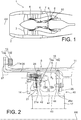
- the figure 2 is partially a stage of the high pressure turbine 8.
- Each stage or the high pressure turbine stage comprises a blade wheel and a distributor (not shown).
- the distributor is part of the stator of the turbomachine. It is divided into annular sectors which each comprise fixed blades spaced apart from each other about the longitudinal axis AX.
- the wheel is rotatable about the longitudinal axis AX of the turbomachine, inside ring sectors 40, only one of which is shown in FIG. figure 2 .
- These ring sectors 40 are spaced from each other around a circumferential direction CC and they are fixed to a support casing 20 via an upstream flange 21.
- the turbine stage comprises a turbine casing 11, the support casing 20, a distributor attachment flange 14 and the upstream flange 21 which is sectored.
- the support casing 20, the attachment flange 14 and the upstream flange 21 together form a support structure of the ring sectors 40.
- Each ring sector 40 has a general shape of inverted pi in longitudinal section.
- the ring sectors 40 are made of a ceramic matrix composite material, which gives them a high thermal resistance to the flow of hot air into the vein of the high-pressure turbine 8.
- Each ring sector 40 comprises an annular base 41, an upstream leg 42 and a downstream leg 44.
- the annular base 41 carries a layer of abradable material 43 which delimits the lower surface of the ring sector.
- the layer of abradable material 43 is intended to come into contact with the top of the corresponding blades 17. It serves to ensure a seal between these blades 17 and the ring sector 40.
- the upstream tab 42 is fixed to the upstream flange 21 by upstream fasteners 19a, only one of which is shown in FIG. figure 2 .
- the downstream tab 44 is fixed to a downstream flange 28 of the support casing 20 by downstream fasteners 19b, only one of which is shown in FIG. figure 2 .
- the upstream fasteners 19a and the downstream fasteners 19b are pins which engage the tabs 42, 44 to limit the radial displacement of the ring sector 40 relative to the blades 17. Together they form fastening means 19 of the ring sector 40 to the support case 20.
- the turbine casing 11 is a casing delimiting the outside of the high-pressure turbine 8. It is mechanically connected to a combustion chamber casing by an upstream fastener 13.
- This upstream fastening member 13 conventionally comprises a screw 13a and a nut 13b. It connects an upstream edge 11a of the turbine casing 11 to an upstream edge 27 of the support casing 20.
- the upstream support case 27 edge is connected to a downstream edge of the combustion chamber casing by the fixing member 13.
- the ring sector support structure is described below with reference to figures 2 and 3 .
- the attachment flange 14 is configured to allow attachment of an upstream distributor. It serves as an axial stop for the upstream distributor. It is designed to transmit mechanical forces from the upstream distributor to the support casing 20, limiting the mechanical forces exerted by the upstream distributor on the ring sectors 40. It is therefore a flange of force recovery of the upstream distributor.
- the flange 14 is mechanically connected to the support casing 20 and to the upstream flange 21 by a fixing member 15.
- the attachment member 15 of the attachment flange conventionally comprises a screw 15a and a clamping member 15b comprising a nut. It connects a downstream face of the fastening flange to the upstream flange 21 and the upstream edge 24 of the support casing.
- the upstream flange 21 extends axially between the fastening flange 14 and an upstream flange 24 of the support casing 20. It is divided into adjacent sectors along the circumferential length C-C. It extends over substantially the entire circumferential length C-C of the housing.
- the upstream flange 21 comprises a lip 21a designed to form a rectilinear support against the upstream leg 42 of the ring sector, to limit leaks between the upstream flange 21 and the ring sector 40.
- the upstream flange 21 serves to fix the upstream leg 42 of the ring sector 40 to the support casing 20 by means of the pins 19a. By being sectored, the upstream flange 21 makes it possible to limit the mechanical stresses of the support casing 20 on the upstream tab 42 of each ring sector 40.
- the support casing 20 is symmetrical with respect to a median plane P of longitudinal section of the support casing. It extends along a longitudinal direction XX in this plane which is substantially parallel to that of the longitudinal axis of the AX turbomachine.
- the support casing 20 is partially annular about its longitudinal axis XX, also extending in a circumferential direction CC about this axis.
- the Figures 3 and 4 represent the angular portion of the support casing 20 which faces the ring sector 40 which is shown in FIG. figure 2 .
- the support housing 20 extends substantially 360 ° about its longitudinal axis XX and has several angular portions such as that shown in FIG. figure 4 .
- axial is a direction substantially parallel to the longitudinal axis XX of the casing 20.
- a radial direction is a direction substantially orthogonal to the axis XX of the support housing 20 and secant with the axis XX of the support housing 20.
- a circumferential direction is a direction about the longitudinal axis XX of the housing of support 20.
- the support casing 20 is made of a metallic material which has a greater mechanical strength than the constituent material of the ring sectors 40, as well as larger thermal expansions.
- the support casing 20 comprises a body 22, an upstream flange 24 and a downstream flange 28. It comprises axially from upstream to downstream an upstream region 25, a central region 23 and a junction region 30 which comprises the downstream flange 28.
- the upstream region 25 comprises the upstream edge 27 for fixing the support casing 20 to the turbine casing 11.
- the upstream edge 27 delimits the support casing 20 axially upstream. It protrudes outwardly from the housing from the central region 23. It extends over substantially the entire circumferential length C-C of the housing.
- the central region 23 comprises the body 22 and the upstream flange 24.
- the body 22 comprises an outer surface Si which is directed towards the turbine casing 11 and an inner surface S 2 which is directed towards the blades 17 and which is opposed to the outer surface S 1 .
- the outer surface S 1 and the inner surface S 2 extend axially. They each form a flat surface of the body 22.
- the outer surface Si is radially opposite to the inner surface S 2 .
- the upstream flange 24 extends from the body 22 radially towards the inside of the casing 20. It forms a flange for connecting the upstream flange 21 to the body 22. It is connected to the upstream flange 21 by the fixing member 15.
- the junction region 30 forms a downstream region of the support housing 20. It comprises a first connection region 30a, the downstream flange 28 and a second connection region 30b.
- the junction region 30 serves to connect the support case 20 to a distributor located downstream of the blades 17.
- the first connection region 30a is located axially between the body 22 and the second connection region 30b. It is configured to connect the body 22 to the downstream flange 28. It has a plurality of circumferential edges each associated with a ring sector 40 which are adjacent to each other in the circumferential direction CC and which each have a circumferential length equal to that of one of the ring sectors 40.
- Each circumferential edge comprises a central portion 31 and two lateral portions 33, 35 which are located on either side of the central portion 31 in the circumferential direction C-C.
- the second connection region 30b is configured to connect the support case 20 to the dispenser. It comprises a downstream edge 37 fixing which delimits the support casing 20 downstream.
- the downstream edge 37 protrudes outwardly from the housing from the central region 23. It extends over substantially the entire circumferential length C-C of the housing.
- the downstream fixing edge 37 serves to fix the support casing 20 to the distributor which is situated downstream of the moving blade wheel 17.
- the downstream rim 28 extends from the body 22 radially inwardly of the housing 20. It is located axially in a downstream region of the circumferential edge 30a. It extends over substantially the entire circumferential length C-C of the housing. It is integral with the body 22, to limit air leakage between the ring sectors 40 and the downstream flange 28.
- the downstream flange 28 comprises a lip 28a designed to form a rectilinear support against the downstream tab 44, to limit leaks between the downstream flange 28 and each ring sector 40, especially at the junction of two ring sectors set circumferentially end to end.
- the downstream flange 28 is a flange for fixing the downstream tab 44 of the ring sector 40.
- the sectorized nature of the ring sectors 40 facing the downstream flange 28 monoblock tends to increase the mechanical stresses that are exerted by the downstream flange 28 on the ring sectors 40.
- the distance between the outer surface S 1 of the housing and the lip 28a is variable along the circumferential direction CC, which tends to vary the intensity of the mechanical forces exerted by the support casing 20 circumferentially on the ring sectors 40.
- the mechanical stresses exerted by the support case 20 then tend to be maximum at the ends of the ring sectors 40, which is detrimental to their mechanical strength.
- Each central portion 31 and the corresponding lateral portions 33, 35 are designed to reduce the maximum intensity of the mechanical forces which are exerted by the support casing 20 on the ring sectors 40. They lead to a more uniform distribution of the mechanical forces transmitted by the support housing 20 to the ring sectors 40 along the first connection region 30a.
- the first connecting region 30a extends substantially over the entire circumferential length CC of the ring sector 40 which is shown in FIG. figure 2 . It is located axially between the upstream flange 24 and the downstream fixing edge 37.
- the central portion 31 projects radially outwardly relative to the outer surface Si of the body 22. It forms a boss of the support housing 20.
- the rigidity of the support housing 20 is increased locally at the central portion 31 This local increase in rigidity of the casing 20 compensates for the greater lever arm between the outer surface Si at the central portion 31 and the lip 28a of the downstream flange at the central portion 31.
- the first lateral portion 33 forms a recess of the casing 20 relative to the outer surface Si at the body 22.
- the rigidity of the support casing 20 is decreased locally at the first lateral portion 33. This local reduction in crankcase rigidity 20 compensates for the weaker lever between the outer surface If at the level of the first lateral portion 33 and the lip 28a of the downstream flange at the level of the first lateral portion 33.
- the second lateral portion 35 also forms a recess of the casing 20 with respect to the external surface Si at the body 22.
- the second lateral portion 35 has substantially the same shape as the first lateral portion 33.
- the rigidity of the support casing 20 is decreased locally at the second lateral portion 35. This local decrease in stiffness of the housing 20 compensates for the weaker lever between the outer surface Si at the second lateral portion 35 and the lip 28a of the downstream flange at the level of the second lateral portion 35.
- the maximum height h of the central portion 31 with respect to each of the lateral portions 33, 35 is between 3 mm and 30 mm.
- the circumferential length l 1 of the central portion 31 with respect to the length L of the circumferential edge associated with the ring sector 40 is between 1/5 and 4/5.
- the circumferential length l 2 of the first lateral portion 33 with respect to the length L of the circumferential edge associated with the ring sector 40 is between 1/10 and 2/5.
- the circumferential length l 3 of the second lateral portion 35 is identical to that of the first lateral portion 33.
- the first connection region 30a thus makes it possible to reduce the intensity of the tensile forces exerted on the ring sectors 40, while reducing the leaks between the downstream flange 28 and the ring sectors 40.
- the central portion 31 and the lateral portions 33, 35 of each of the circumferential edges of the first connection region 30a make it possible to reduce the maximum intensity of the mechanical forces that are exerted by the support casing 20 on the ring sectors 40, while limiting the air leakage at the junction between the ring sector 40 and the support casing 20.
- the mass of the support casing 20 is also limited, in particular being substantially identical to that of a support casing 20 with a first uniform connection region 30a in the circumferential direction CC.
- the support housing 20 may be used to connect low pressure turbine rotor blades 10 to the turbine housing 11.
- the shape of the support casing 20 is variable.
- the support casing 20 may be unsymmetrical around its longitudinal axis X-X. It can also extend over an angular distance of less than 360 ° around its longitudinal axis X-X, being sectored.
- the shape of the first connection region 30a is variable.
- the shape of each central portion 31 may vary, as may its length l 1 and its height h with respect to the lateral portions 33, 35.
- the shape of each of the lateral portions 33, 35 may vary, from same as their length l 2 , l 3 and their depth.
- the shape, length and depth of the second lateral portion 35 may vary from those of the first lateral portion 33 of the circumferential edge.
Landscapes
- Engineering & Computer Science (AREA)
- Mechanical Engineering (AREA)
- General Engineering & Computer Science (AREA)
- Chemical & Material Sciences (AREA)
- Materials Engineering (AREA)
- Ceramic Engineering (AREA)
- Architecture (AREA)
- Turbine Rotor Nozzle Sealing (AREA)
Abstract
Description
- L'invention se rapporte au domaine technique des turbomachines d'aéronef telles que les turboréacteurs et les turbopropulseurs. Plus précisément, l'invention concerne les carters de turbine haute pression pour turbomachine.
- Chaque étage d'une turbine haute pression pour turbomachine comprend une roue d'aubes mobiles et un distributeur doté d'aubes fixes. La roue est mobile en rotation relativement au distributeur autour de l'axe longitudinal de la turbomachine et à l'intérieur d'un anneau sectorisé.
- Cet anneau sectorisé est fixé à un carter de support qui est relié mécaniquement au distributeur. Le carter de support comprend un corps annulaire. Il comporte un rebord amont et un rebord aval entre lesquels sont fixés les secteurs d'anneau.
- Les secteurs d'anneaux sont réalisés de manière connue en matériau composite à matrice céramique, tandis que le carter de support est réalisé en matériau métallique. Le matériau constitutif des secteurs d'anneaux présente un coefficient de dilatation différentiel supérieur à celui du matériau constitutif du carter de support. Un tel carter de support et de tels secteurs anneaux sont par exemple connus du brevet
FR 3 041993 - Du fait de cette différence de matériau, les dilatations différentielles des secteurs d'anneau relativement au carter de support sont importantes, ce qui a tendance à provoquer des fuites. Les secteurs d'anneaux présentent aussi une grande rigidité et une faible résistance mécanique par rapport au carter de support.
- Or, les secteurs d'anneaux sont serrés avec une contrainte à froid au carter de support pour, qu'en fonctionnement de la turbomachine, les fuites entre les secteurs d'anneaux et le carter de support soient limitées, malgré les dilatations différentielles. Les efforts mécaniques transmis par le carter de support aux secteurs d'anneaux peuvent donc être très élevés.
- Il existe donc un besoin de limiter les efforts mécaniques transmis par le carter de support aux secteurs d'anneau, tout en limitant les fuites d'air entre les secteurs d'anneaux et le carter de support.
- L'invention vise à résoudre au moins partiellement les problèmes rencontrés dans les solutions de l'art antérieur.
- A cet égard, l'invention a pour objet un carter de support pour secteur d'anneau de turbomachine. Le carter de support comprend un corps annulaire autour d'un axe longitudinal du carter, et un rebord aval de fixation du secteur d'anneau.
- Le rebord aval s'étend depuis le corps radialement vers l'intérieur du carter et circonférentiellement le long d'une région de jonction du corps à un distributeur.
- La région de jonction comprend une première région de raccordement configurée pour raccorder le corps au rebord aval et une deuxième région de raccordement configurée pour être fixée au distributeur.
- Selon l'invention, la première région de raccordement comprend, selon une direction circonférentielle du carter relativement à son axe longitudinal, une portion centrale et deux portions latérales qui sont situées de part et d'autre de la portion centrale. La portion centrale est en saillie radialement vers l'extérieur du carter par rapport aux portions latérales.
- Grâce au carter de support selon l'invention, l'intensité des efforts mécaniques exercés par le carter de support sur le secteur d'anneau est réduite, tout en limitant les fuites d'air à la jonction entre le secteur d'anneau et le carter de support, et tout en limitant la masse de la turbomachine.
- En particulier, le carter de support selon l'invention présente une rigidité réduite au niveau des portions latérales par rapport à la rigidité du carter au niveau de la portion centrale, ce qui conduit à une répartition plus uniforme des efforts mécaniques transmis par le carter de support au secteur d'anneau. Le contact mécanique amélioré du carter de support et du secteur d'anneau lors du fonctionnement du module permet également de réduire les fuites entre le carter de support et le secteur d'anneau.
- La portion centrale s'étend notamment depuis une surface axiale externe du corps en étant en saillie radialement vers l'extérieur par rapport aux portions latérales.
- L'invention peut comporter de manière facultative une ou plusieurs des caractéristiques suivantes combinées entre elles ou non.
- Avantageusement, au moins une des portions latérales comprend un évidement d'une surface externe du corps.
- Selon une particularité de réalisation, la portion centrale comprend une portion en saillie de la surface externe du corps. De préférence, la portion en saillie comprend un bossage. Un bossage est de préférence prévu pour chacun des secteurs d'anneau d'étanchéité.
- Selon une forme de réalisation avantageuse, le carter de support comprend un rebord amont de fixation du secteur d'anneau, le rebord amont s'étendant depuis le corps radialement vers l'intérieur du carter et circonférentiellement le long du corps.
- Selon une autre forme de réalisation avantageuse, la deuxième région de raccordement comprend un bord aval de fixation qui est situé en aval de la portion centrale et des portions latérales, pour fixer le carter au distributeur.
- Selon une particularité de réalisation, la hauteur maximale de saillie de la portion centrale par rapport à au moins une des portions latérales est comprise entre 3 mm et 30 mm.
- Selon une autre particularité de réalisation la longueur circonférentielle de la portion centrale par rapport à la longueur circonférentielle d'un secteur d'anneau est comprise entre 1/5 et 4/5.
- En particulier, la longueur circonférentielle du bossage de la portion centrale par rapport à la longueur circonférentielle du secteur d'anneau est comprise entre 1/5 et 4/5.
- Selon une autre particularité de réalisation la longueur circonférentielle d'au moins une des portions latérales par rapport à la longueur circonférentielle d'un secteur d'anneau est comprise entre 1/10 et 2/5.
- Avantageusement, la région de jonction est sensiblement symétrique par rapport à un plan médian de coupe longitudinale du carter de support.
- De préférence, le carter de support est sensiblement symétrique par rapport au plan médian.
- Selon une particularité de réalisation, le rebord aval comprend une lèvre destinée à être en contact avec une patte aval du secteur d'anneau.
- L'invention porte également sur un ensemble d'anneau de turbine comprenant un carter tel que défini ci-dessus et un secteur d'anneau qui est fixé au carter. Le secteur d'anneau comprend une patte amont qui est fixée au rebord amont du carter de support et une patte aval qui est fixée au rebord aval, de préférence par des pions.
- De préférence, le carter de support est réalisé dans un matériau métallique.
- De préférence, le secteur d'anneau est réalisé dans un matériau composite à matrice céramique.
- Selon une particularité de réalisation, l'ensemble d'anneau comprend une pluralité de secteurs d'anneaux adjacents les uns des autres selon la direction circonférentielle et fixés au carter de support.
- La première région de raccordement comprend notamment selon la direction circonférentielle autant de portions centrales que l'ensemble comprend de secteurs d'anneau. Chaque portion centrale est située circonférentiellement entre deux portions latérales. Chaque portion centrale est en saillie radialement vers l'extérieur du carter par rapport aux portions latérales qui sont adjacentes à cette portion centrale.
- L'invention se rapporte aussi à une turbine pour turbomachine, comprenant un ensemble d'anneaux tel que défini ci-dessus.
- De préférence, la turbine est une turbine haute pression.
- De préférence, un distributeur haute pression est fixé mécaniquement au carter de support, en amont du secteur d'anneau.
- Enfin, l'invention se rapporte à une turbomachine comprenant une turbine telle que décrite ci-dessus.
- La présente invention sera mieux comprise à la lecture de la description d'exemples de réalisation, donnés à titre purement indicatif et nullement limitatif, en faisant référence aux dessins annexés sur lesquels :
- la
figure 1 est une représentation schématique partielle en coupe longitudinale d'une turbomachine, selon un premier mode de réalisation de l'invention ; - la
figure 2 est une représentation schématique partielle en coupe longitudinale d'une turbine haute pression de la turbomachine selon le premier mode de réalisation ; - la
figure 3 est une représentation schématique partielle d'une structure de support d'anneau de turbine haute pression selon le premier mode de réalisation ; - la
figure 4 est une représentation schématique partielle en perspective d'une portion angulaire de carter de support de la turbine haute pression de la turbomachine selon le premier mode de réalisation. - Des parties identiques, similaires ou équivalentes des différentes figures portent les mêmes références numériques de façon à faciliter le passage d'une figure à l'autre.
- La
figure 1 représente une turbomachine 1 à double flux et double corps. La turbomachine 1 est un turboréacteur qui a une forme de révolution autour d'un axe longitudinal AX. - La turbomachine 1 comprend, de l'amont vers l'aval sur le chemin d'un flux primaire, une manche d'entrée d'air 2, une soufflante 3, un compresseur basse pression 4, un compresseur haute pression 6, une chambre de combustion 7, une turbine haute pression 8 et une turbine basse pression 10.
- Les directions amont et aval sont utilisés dans ce document en référence à l'écoulement global des gaz dans la turbomachine 1, une telle direction est sensiblement parallèle à la direction de l'axe longitudinal AX.
- Le compresseur basse pression 4, le compresseur haute pression 6, la turbine haute pression 8 et la turbine basse pression 10 délimitent une veine primaire d'écoulement du flux primaire. Ils sont entourés par une veine secondaire de la turbomachine 1.
- Le compresseur haute pression 6 et la turbine haute pression 8 sont reliées mécaniquement par un arbre d'entraînement du compresseur haute pression 6, pour former un corps haute pression de la turbomachine 1. De manière similaire, le compresseur basse pression 4 et la turbine basse pression 10 sont reliées mécaniquement par un arbre de turbomachine, de façon à former un corps basse pression de la turbomachine 1.
- Le compresseur basse pression 4, le compresseur haute pression 6, la chambre de combustion 7, la turbine haute pression 8 et la turbine basse pression 10 sont entourés par un carter 9 qui s'étend depuis la manche d'entrée 2 jusqu'à la turbine basse pression 10.
- La
figure 2 représente partiellement un étage de la turbine haute pression 8. Chaque étage ou l'étage de turbine haute pression comprend une roue d'aubes mobiles et un distributeur (non représenté). - Le distributeur fait partie du stator de la turbomachine. Il est divisé en secteurs annulaires qui comprennent chacun des aubes fixes espacées les unes des autres autour de l'axe longitudinal AX.
- La roue est mobile en rotation autour de l'axe longitudinal AX de la turbomachine, à l'intérieur de secteurs d'anneau 40 dont un seul est représenté à la
figure 2 . Ces secteurs d'anneaux 40 sont espacés les uns des autres autour d'une direction circonférentielle C-C et ils sont fixés à un carter de support 20 par l'intermédiaire d'un flasque amont 21. - L'étage de turbine comprend un carter de turbine 11, le carter de support 20, un flasque d'accrochage 14 de distributeur et le flasque amont 21 qui est sectorisé. Le carter de support 20, le flasque d'accrochage 14 et le flasque amont 21 forment conjointement une structure de support des secteurs d'anneaux 40.
- Chaque secteur d'anneau 40 présente une forme générale de pi renversé en section longitudinale. Les secteurs d'anneau 40 sont réalisés dans un matériau composite à matrice céramique, ce qui leur confère une résistance thermique importante au flux d'air chaud dans la veine de la turbine haute pression 8.
- Chaque secteur d'anneau 40 comprend une base annulaire 41, une patte amont 42 et une patte aval 44. La base annulaire 41 porte une couche de matériau abradable 43 qui délimite la surface inférieure du secteur d'anneau. La couche de matériau abradable 43 est destinée à venir au contact du sommet des aubes mobiles 17 correspondantes. Elle sert à assurer une étanchéité entre ces aubes 17 et le secteur d'anneau 40.
- La patte amont 42 est fixée au flasque amont 21 par des attaches amont 19a dont une seule est représentée à la
figure 2 . La patte aval 44 est fixée à un rebord aval 28 du carter de support 20 par des attaches aval 19b dont une seule est représentée à lafigure 2 . - Les attaches amont 19a et les attaches aval 19b sont des pions qui engagent les pattes 42, 44 pour limiter le déplacement radial du secteur d'anneau 40 relativement aux aubes mobiles 17. Elles forment conjointement des moyens de fixation 19 du secteur d'anneau 40 au carter de support 20.
- Le carter de turbine 11 est un carter délimitant l'extérieur de la turbine haute pression 8. Il est raccordé mécaniquement à un carter de chambre de combustion par un organe de fixation amont 13.
- Cet organe de fixation amont 13 comprend de manière classique une vis 13a et un écrou 13b. Il raccorde un bord amont 11a du carter de turbine 11 à un bord amont 27 du carter de support 20. Le bord amont 27 de carter de support est raccordé à un bord aval de carter de chambre de combustion par l'organe de fixation 13.
- La structure de support de secteurs d'anneaux est décrite ci-dessous en référence conjointe aux
figures 2 et3 . - Le flasque d'accrochage 14 est configuré pour permettre l'accrochage d'un distributeur amont. Il sert de butée axiale au distributeur amont. Il est conçu pour transmettre des efforts mécaniques du distributeur amont au carter de support 20, en limitant les efforts mécaniques exercés par ce distributeur amont sur les secteurs d'anneaux 40. Il s'agit donc d'un flasque de reprise d'effort du distributeur amont. Le flasque 14 est raccordé mécaniquement au carter de support 20 et au flasque amont 21 par un organe de fixation 15.
- L'organe de fixation 15 du flasque d'accrochage comprend de manière classique une vis 15a et un organe de serrage 15b comprenant un écrou. Il raccorde une face aval du flasque de d'accrochage au flasque amont 21 et au rebord amont 24 du carter de support.
- Le flasque amont 21 s'étend axialement entre le flasque d'accrochage 14 et un rebord amont 24 du carter de support 20. Il est divisé en secteurs adjacents selon la longueur circonférentielle C-C. Il s'étend sur sensiblement toute la longueur circonférentielle C-C du carter.
- Le flasque amont 21 comprend une lèvre 21a conçue pour former un appui rectiligne contre la patte amont 42 du secteur d'anneau, pour limiter les fuites entre le flasque amont 21 et le secteur d'anneau 40. Le flasque amont 21 sert à fixer la patte amont 42 du secteur d'anneau 40 au carter de support 20 au moyen des pions 19a. En étant sectorisé, le flasque amont 21 permet de limiter les efforts mécaniques du carter de support 20 sur la patte amont 42 de chaque secteur d'anneau 40.
- En référence conjointe aux
figures 2 à 4 , le carter de support 20 est symétrique par rapport à un plan médian P de coupe longitudinale du carter de support. Il s'étend le long d'une direction longitudinale X-X dans ce plan qui est sensiblement parallèle à celle de l'axe longitudinal de la turbomachine AX. Le carter de support 20 est partiellement annulaire autour de son axe longitudinal X-X, en s'étendant également selon une direction circonférentielle C-C autour de cet axe. - Les
figures 3 et 4 représentent la portion angulaire de carter de support 20 qui est en regard du secteur d'anneau 40 qui est représenté à lafigure 2 . Le carter de support 20 s'étend sensiblement sur 360° autour de son axe longitudinal X-X et il comporte plusieurs portions angulaires telles que celle représentée à lafigure 4 . - Sauf précision contraire, les adjectifs « axial », « radial » et « circonférentiel » sont définis par rapport à l'axe de révolution X-X du carter de support 20. Une direction axiale est une direction sensiblement parallèle à l'axe longitudinal X-X du carter de support 20. Une direction radiale est une direction sensiblement orthogonale à l'axe X-X du carter de support 20 et sécante avec l'axe X-X du carter de support 20. Une direction circonférentielle est une direction autour de l'axe longitudinal X-X du carter de support 20.
- Le carter de support 20 est réalisé dans un matériau métallique qui présente une plus grande résistance mécanique que le matériau constitutif des secteurs d'anneaux 40, ainsi que des dilatations thermiques plus importantes.
- Le carter de support 20 comprend un corps 22, un rebord amont 24 et un rebord aval 28. Il comprend axialement d'amont en aval une région amont 25, une région centrale 23 et une région de jonction 30 qui comprend le rebord aval 28.
- La région amont 25 comprend le bord amont 27 de fixation du carter de support 20 au carter de turbine 11. Le bord amont 27 délimite le carter de support 20 axialement vers l'amont. Il est en saillie vers l'extérieur du carter depuis la région centrale 23. Il s'étend sur sensiblement toute la longueur circonférentielle C-C du carter.
- La région centrale 23 comprend le corps 22 et le rebord amont 24. Le corps 22 comprend une surface externe Si qui est dirigée vers le carter de turbine 11 et une surface interne S2 qui est dirigée vers les aubes mobiles 17 et qui est opposée à la surface externe S1. La surface externe S1 et la surface interne S2 s'étendent axialement. Elles forment chacune une surface de plat du corps 22. La surface externe Si est radialement opposée à la surface interne S2.
- Le rebord amont 24 s'étend depuis le corps 22 radialement vers l'intérieur du carter 20. Il forme une bride de raccordement du flasque amont 21 au corps 22. Il est raccordé au flasque amont 21 par l'organe de fixation 15.
- La région de jonction 30 forme une région aval du carter de support 20. Elle comprend une première région de raccordement 30a, le rebord aval 28 et une deuxième région de raccordement 30b. La région de jonction 30 sert à raccorder le carter de support 20 à un distributeur situé en aval des aubes mobiles 17.
- La première région de raccordement 30a est située axialement entre le corps 22 et la deuxième région de raccordement 30b. Elle est configurée pour raccorder le corps 22 au rebord aval 28. Elle comporte une pluralité de bordures circonférentielles chacune associée à un secteur d'anneau 40 qui sont adjacentes les unes aux autres selon la direction circonférentielle C-C et qui ont chacune une longueur circonférentielle égale à celle d'un des secteurs d'anneau 40.
- Chaque bordure circonférentielle comporte une portion centrale 31 et deux portions latérales 33, 35 qui sont situées de part et d'autre de la portion centrale 31 selon la direction circonférentielle C-C.
- La deuxième région de raccordement 30b est configurée pour raccorder le carter de support 20 au distributeur. Elle comprend un bord aval 37 de fixation qui délimite le carter de support 20 vers l'aval. Le bord aval 37 est en saillie vers l'extérieur du carter depuis la région centrale 23. Il s'étend sur sensiblement toute la longueur circonférentielle C-C du carter. Le bord aval 37 de fixation sert à fixer le carter de support 20 au distributeur qui est situé en aval de la roue d'aubes mobiles 17.
- Le rebord aval 28 s'étend depuis le corps 22 radialement vers l'intérieur du carter 20. Il est situé axialement dans une région aval de la bordure circonférentielle 30a. Il s'étend sur sensiblement toute la longueur circonférentielle C-C du carter. Il est monobloc avec le corps 22, pour limiter les fuites d'air entre les secteurs d'anneau 40 et le rebord aval 28.
- Le rebord aval 28 comprend une lèvre 28a conçue pour former un appui rectiligne contre la patte aval 44, pour limiter les fuites entre le rebord aval 28 et chaque secteur d'anneau 40, notamment au niveau de la jonction de deux secteurs d'anneau mis circonférentiellement bout à bout. Le rebord aval 28 est un rebord de fixation de la patte aval 44 du secteur d'anneau 40.
- Le caractère sectorisé des secteurs d'anneau 40 en regard du rebord aval 28 monobloc tend à accroitre les contraintes mécaniques qui sont exercées par le rebord aval 28 sur les secteurs d'anneaux 40. La distance entre la surface externe S1 du carter et la lèvre 28a est variable le long de la direction circonférentielle C-C, ce qui tend à faire varier l'intensité des efforts mécaniques exercés par le carter de support 20 circonférentiellement sur les secteurs d'anneau 40. Les contraintes mécaniques exercées par le carter de support 20 tendent alors à être maximales au niveau des extrémités des secteurs d'anneau 40, ce qui est préjudiciable à leur tenue mécanique.
- Chaque portion centrale 31 et les portions latérales 33, 35 correspondantes sont conçues pour réduire l'intensité maximale des efforts mécaniques qui sont exercés par le carter de support 20 sur les secteurs d'anneau 40. Elles conduisent à une répartition plus uniforme des efforts mécaniques transmis par le carter de support 20 aux secteurs d'anneau 40 le long de la première région de raccordement 30a.
- En référence à la
figure 4 , la première région de raccordement 30a s'étend sensiblement sur toute la longueur circonférentielle C-C du secteur d'anneau 40 qui est représentée à lafigure 2 . Elle est située axialement entre le rebord amont 24 et le bord aval de fixation 37. - La portion centrale 31 est en saillie radialement vers l'extérieur par rapport à la surface externe Si du corps 22. Elle forme un bossage du carter de support 20. La rigidité du carter de support 20 est accrue localement au niveau de la portion centrale 31. Cette augmentation locale de rigidité du carter 20 compense le bras de levier plus important entre la surface externe Si au niveau de la portion centrale 31 et la lèvre 28a du rebord aval au niveau de la portion centrale 31.
- La première portion latérale 33 forme un évidement du carter 20 par rapport à la surface externe Si au niveau du corps 22. La rigidité du carter de support 20 est diminuée localement au niveau de la première portion latérale 33. Cette diminution locale de rigidité du carter 20 compense le bras de levier plus faible entre la surface externe Si au niveau de la première portion latérale 33 et la lèvre 28a du rebord aval au niveau de la première portion latérale 33.
- La deuxième portion latérale 35 forme aussi un évidement du carter 20 par rapport à la surface externe Si au niveau du corps 22. La deuxième portion latérale 35 a sensiblement la même forme que la première portion latérale 33. La rigidité du carter de support 20 est diminuée localement au niveau de la deuxième portion latérale 35. Cette diminution locale de rigidité du carter 20 compense le bras de levier plus faible entre la surface externe Si au niveau de la deuxième portion latérale 35 et la lèvre 28a du rebord aval au niveau de la deuxième portion latérale 35.
- La hauteur maximale h de la portion centrale 31 par rapport à chacune des portions latérales 33, 35 est comprise entre 3 mm 30 mm.
- La longueur circonférentielle l1 de la portion centrale 31 par rapport à la longueur L de la bordure circonférentielle associée au secteur d'anneau 40 est comprise entre 1/5 et 4/5.
- La longueur circonférentielle l2 de la première portion latérale 33 par rapport à la longueur L de la bordure circonférentielle associée au secteur d'anneau 40 est comprise entre 1/10 et 2/5. La longueur circonférentielle l3 de la deuxième portion latérale 35 est identique à celle de la première portion latérale 33.
- La première région de raccordement 30a permet ainsi de réduire l'intensité des efforts de traction exercés sur les secteurs d'anneau 40, tout en réduisant les fuites entre le rebord aval 28 et les secteurs d'anneaux 40.
- La portion centrale 31 et les portions latérales 33, 35 de chacune des bordures circonférentielles de la première région de raccordement 30a permettent de réduire l'intensité maximale des efforts mécaniques qui sont exercés par le carter de support 20 sur les secteurs d'anneau 40, tout en limitant les fuites d'air à la jonction entre le secteur d'anneau 40 et le carter de support 20. La masse du carter de support 20 est également limitée, en étant notamment sensiblement identique à celle d'un carter de support 20 avec une première région de raccordement 30a uniforme selon la direction circonférentielle C-C.
- Bien entendu, diverses modifications peuvent être apportées par l'homme du métier à l'invention qui vient d'être décrite sans sortir du cadre de l'exposé de l'invention.
- Le carter de support 20 peut être utilisé pour raccorder des aubes de rotor de turbine basse pression 10 au carter de turbine 11.
- La forme du carter de support 20 est variable. Par exemple, le carter de support 20 peut être non symétrique autour de son axe longitudinal X-X. Il peut aussi s'étendre sur une distance angulaire inférieure à 360° autour de son axe longitudinal X-X, en étant sectorisé.
- La forme de la première région de raccordement 30a est variable. En particulier, la forme de chaque portion centrale 31 peut varier, de même que sa longueur l1 et sa hauteur h par rapport aux portions latérales 33, 35. De même, la forme de chacune des portions latérales 33, 35 peut varier, de même que leur longueur l2, l3 et leur profondeur. La forme, la longueur et la profondeur de la deuxième portion latérale 35 peuvent varier par rapport à celles de la première portion latérale 33 de la bordure circonférentielle.
Claims (10)
- Carter de support (20) pour secteur d'anneau d'étanchéité (40) de turbomachine, comprenant :un corps (22) annulaire autour d'un axe longitudinal (X-X) du carter, comprenant une surface interne (S2) et une surface externe (Si) opposée à la surface interne qui s'étendent axialement le long de l'axe longitudinal (X-X),un rebord aval (28) configuré pour la fixation du secteur d'anneau (40), le rebord aval (28) s'étendant depuis le corps (22) radialement vers l'intérieur du carter (20) et circonférentiellement le long d'une région de jonction (30) du corps à un distributeur,la région de jonction (30) comprenant une première région de raccordement (30a) configurée pour raccorder le corps (22) au rebord aval (28) et une deuxième région de raccordement (30b) configurée pour être fixée au distributeur,la portion centrale (31) s'étendant depuis la surface externe (Si) en étant en saillie vers l'extérieur du carter (20) par rapport aux portions latérales (33, 35).caractérisé en ce que la première région de raccordement (30a) comprend, selon une direction circonférentielle (C-C) du carter relativement à son axe longitudinal (X-X), au moins une portion centrale (31) et deux portions latérales (33, 35) qui sont situées de part et d'autre de la portion centrale (31),
- Carter (20) selon la revendication précédente, dans lequel au moins une des portions latérales (33, 35) comprend un évidement de la surface externe (Si) du corps.
- Carter (20) selon l'une quelconque des revendications précédentes, dans lequel la portion centrale (31) comprend une portion en saillie de la surface externe (Si) du corps, la portion en saillie comprenant de préférence un bossage.
- Carter (20) selon l'une quelconque des revendications précédentes, comprenant un rebord amont (24) de fixation du secteur d'anneau (40), le rebord amont (24) s'étendant depuis le corps (22) radialement vers l'intérieur du carter (20) et circonférentiellement le long du corps (22),
la deuxième région de raccordement (30b) comprenant un bord aval de fixation (37) qui est situé en aval de la portion centrale (31) et des portions latérales (33, 35), pour fixer le carter (20) au distributeur. - Carter (20) selon l'une quelconque des revendications précédentes, dans lequel la hauteur (h) maximale de saillie de la portion centrale (31) par rapport à au moins une des portions latérales (33, 35) est comprise entre 3 mm et 30 mm, et/ou dans lequel
la longueur circonférentielle (l1) de la portion centrale (31) par rapport à la longueur circonférentielle (L) d'un secteur d'anneau (40) est comprise entre 1/5 et 4/5, et/ou dans lequel
la longueur circonférentielle (l2, l3) d'au moins une des portions latérales (33, 35) par rapport à la longueur circonférentielle (L) d'un secteur d'anneau (40) est comprise entre 1/10 et 2/5. - Carter (20) selon l'une quelconque des revendications précédentes, dans lequel la région de jonction (30) est sensiblement symétrique par rapport à un plan médian (P) de coupe longitudinale du carter de support (20), le carter de support (20) étant de préférence sensiblement symétrique par rapport au plan médian (P).
- Carter (20) selon l'une quelconque des revendications précédentes, dans lequel le rebord aval (28) comprend une lèvre (28a) destinée à être en contact avec une patte aval (44) du secteur d'anneau (40).
- Ensemble d'anneau de turbine comprenant un carter (20) selon l'une quelconque des revendications précédentes et un secteur d'anneau (40) qui est fixé au carter (20),
le secteur d'anneau (40) comprenant une patte amont (42) qui est fixée au rebord amont (24) du carter de support (20) et une patte aval (44) qui est fixée au rebord aval (28) du carter de support (20), de préférence par des pions (19a, 19b),le carter de support (20) étant de préférence réalisé dans un matériau métallique et le secteur d'anneau (40) étant de préférence réalisé dans un matériau composite à matrice céramique. - Ensemble d'anneau selon la revendication précédente, comprenant une pluralité de secteurs d'anneaux (40) adjacents les uns des autres selon la direction circonférentielle (C-C) et fixés au carter de support (20),
la première région de raccordement (30a) comprenant selon la direction circonférentielle (C-C) autant de portions centrales (31) que l'ensemble comprend de secteurs d'anneau (40), chaque portion centrale (31) étant située circonférentiellement entre deux portions latérales (33, 35),
chaque portion centrale (31) étant en saillie radialement vers l'extérieur du carter (20) par rapport aux portions latérales (33, 35) qui sont adjacentes à cette portion centrale (31) selon la direction circonférentielle (C-C). - Turbine (8, 10) pour turbomachine, comprenant un ensemble d'anneau selon la revendication 8 ou 9, la turbine (8, 10) étant de préférence une turbine haute pression (8), un distributeur haute pression étant de préférence fixé mécaniquement au carter de support (20) en amont du secteur d'anneau (40).
Applications Claiming Priority (1)
| Application Number | Priority Date | Filing Date | Title |
|---|---|---|---|
| FR1759986A FR3072720B1 (fr) | 2017-10-23 | 2017-10-23 | Carter pour turbomachine comprenant une portion centrale en saillie relativement a deux portions laterales dans une region de jonction |
Publications (2)
| Publication Number | Publication Date |
|---|---|
| EP3473806A1 true EP3473806A1 (fr) | 2019-04-24 |
| EP3473806B1 EP3473806B1 (fr) | 2020-05-13 |
Family
ID=60765883
Family Applications (1)
| Application Number | Title | Priority Date | Filing Date |
|---|---|---|---|
| EP18201699.8A Active EP3473806B1 (fr) | 2017-10-23 | 2018-10-22 | Carter pour turbomachine comprenant une portion centrale en saillie relativement à deux portions latérales dans une région de jonction |
Country Status (3)
| Country | Link |
|---|---|
| US (1) | US10934872B2 (fr) |
| EP (1) | EP3473806B1 (fr) |
| FR (1) | FR3072720B1 (fr) |
Families Citing this family (20)
| Publication number | Priority date | Publication date | Assignee | Title |
|---|---|---|---|---|
| FR3055147B1 (fr) * | 2016-08-19 | 2020-05-29 | Safran Aircraft Engines | Ensemble d'anneau de turbine |
| FR3055148B1 (fr) * | 2016-08-19 | 2020-06-05 | Safran Aircraft Engines | Ensemble d'anneau de turbine |
| US11313233B2 (en) | 2019-08-20 | 2022-04-26 | Rolls-Royce Corporation | Turbine vane assembly with ceramic matrix composite parts and platform sealing features |
| US11066947B2 (en) | 2019-12-18 | 2021-07-20 | Rolls-Royce Corporation | Turbine shroud assembly with sealed pin mounting arrangement |
| FR3108672B1 (fr) * | 2020-03-24 | 2023-06-02 | Safran Aircraft Engines | Ensemble d'anneau de turbine |
| US11255210B1 (en) | 2020-10-28 | 2022-02-22 | Rolls-Royce Corporation | Ceramic matrix composite turbine shroud assembly with joined cover plate |
| US11286812B1 (en) | 2021-05-25 | 2022-03-29 | Rolls-Royce Corporation | Turbine shroud assembly with axially biased pin and shroud segment |
| US11346251B1 (en) | 2021-05-25 | 2022-05-31 | Rolls-Royce Corporation | Turbine shroud assembly with radially biased ceramic matrix composite shroud segments |
| US11629607B2 (en) | 2021-05-25 | 2023-04-18 | Rolls-Royce Corporation | Turbine shroud assembly with radially and axially biased ceramic matrix composite shroud segments |
| US11761351B2 (en) | 2021-05-25 | 2023-09-19 | Rolls-Royce Corporation | Turbine shroud assembly with radially located ceramic matrix composite shroud segments |
| US11346237B1 (en) | 2021-05-25 | 2022-05-31 | Rolls-Royce Corporation | Turbine shroud assembly with axially biased ceramic matrix composite shroud segment |
| US11499444B1 (en) | 2021-06-18 | 2022-11-15 | Rolls-Royce Corporation | Turbine shroud assembly with forward and aft pin shroud attachment |
| US11441441B1 (en) | 2021-06-18 | 2022-09-13 | Rolls-Royce Corporation | Turbine shroud with split pin mounted ceramic matrix composite blade track |
| US11319828B1 (en) | 2021-06-18 | 2022-05-03 | Rolls-Royce Corporation | Turbine shroud assembly with separable pin attachment |
| US12031443B2 (en) | 2022-11-29 | 2024-07-09 | Rolls-Royce Corporation | Ceramic matrix composite blade track segment with attachment flange cooling chambers |
| US11773751B1 (en) | 2022-11-29 | 2023-10-03 | Rolls-Royce Corporation | Ceramic matrix composite blade track segment with pin-locating threaded insert |
| US11713694B1 (en) | 2022-11-30 | 2023-08-01 | Rolls-Royce Corporation | Ceramic matrix composite blade track segment with two-piece carrier |
| US11840936B1 (en) | 2022-11-30 | 2023-12-12 | Rolls-Royce Corporation | Ceramic matrix composite blade track segment with pin-locating shim kit |
| US11732604B1 (en) | 2022-12-01 | 2023-08-22 | Rolls-Royce Corporation | Ceramic matrix composite blade track segment with integrated cooling passages |
| US11885225B1 (en) | 2023-01-25 | 2024-01-30 | Rolls-Royce Corporation | Turbine blade track with ceramic matrix composite segments having attachment flange draft angles |
Citations (4)
| Publication number | Priority date | Publication date | Assignee | Title |
|---|---|---|---|---|
| FR2919345A1 (fr) * | 2007-07-26 | 2009-01-30 | Snecma Sa | Anneau pour une roue de turbine de turbomachine. |
| WO2016146942A1 (fr) * | 2015-03-16 | 2016-09-22 | Herakles | Ensemble d'anneau de turbine comprenant une pluralité de secteurs d'anneau en matériau composite a matrice céramique. |
| FR3036433A1 (fr) * | 2015-05-22 | 2016-11-25 | Snecma | Ensemble d'anneau de turbine avec maintien par crabotage |
| US20170101882A1 (en) * | 2015-10-12 | 2017-04-13 | Rolls-Royce Corporation | Turbine shroud with sealing features |
Family Cites Families (6)
| Publication number | Priority date | Publication date | Assignee | Title |
|---|---|---|---|---|
| US9976436B2 (en) * | 2013-03-28 | 2018-05-22 | United Technologies Corporation | Movable air seal for gas turbine engine |
| WO2014168804A1 (fr) * | 2013-04-12 | 2014-10-16 | United Technologies Corporation | Joint étanche à l'air extérieur de pale comportant une étanchéité à l'air secondaire |
| GB2533544B (en) * | 2014-09-26 | 2017-02-15 | Rolls Royce Plc | A shroud segment retainer |
| US10941942B2 (en) * | 2014-12-31 | 2021-03-09 | Rolls-Royce North American Technologies Inc. | Retention system for gas turbine engine assemblies |
| FR3041993B1 (fr) | 2015-10-05 | 2019-06-21 | Safran Aircraft Engines | Ensemble d'anneau de turbine avec maintien axial |
| DE102016115610A1 (de) * | 2016-08-23 | 2018-03-01 | Rolls-Royce Deutschland Ltd & Co Kg | Gasturbine und Verfahren zum Aufhängen eines Turbinen-Leitschaufelsegments einer Gasturbine |
-
2017
- 2017-10-23 FR FR1759986A patent/FR3072720B1/fr active Active
-
2018
- 2018-10-22 US US16/166,435 patent/US10934872B2/en active Active
- 2018-10-22 EP EP18201699.8A patent/EP3473806B1/fr active Active
Patent Citations (4)
| Publication number | Priority date | Publication date | Assignee | Title |
|---|---|---|---|---|
| FR2919345A1 (fr) * | 2007-07-26 | 2009-01-30 | Snecma Sa | Anneau pour une roue de turbine de turbomachine. |
| WO2016146942A1 (fr) * | 2015-03-16 | 2016-09-22 | Herakles | Ensemble d'anneau de turbine comprenant une pluralité de secteurs d'anneau en matériau composite a matrice céramique. |
| FR3036433A1 (fr) * | 2015-05-22 | 2016-11-25 | Snecma | Ensemble d'anneau de turbine avec maintien par crabotage |
| US20170101882A1 (en) * | 2015-10-12 | 2017-04-13 | Rolls-Royce Corporation | Turbine shroud with sealing features |
Also Published As
| Publication number | Publication date |
|---|---|
| FR3072720A1 (fr) | 2019-04-26 |
| FR3072720B1 (fr) | 2019-09-27 |
| US10934872B2 (en) | 2021-03-02 |
| US20190128132A1 (en) | 2019-05-02 |
| EP3473806B1 (fr) | 2020-05-13 |
Similar Documents
| Publication | Publication Date | Title |
|---|---|---|
| FR3072720B1 (fr) | Carter pour turbomachine comprenant une portion centrale en saillie relativement a deux portions laterales dans une region de jonction | |
| EP1607582B1 (fr) | Montage de chambre de combustion de turbine à gaz avec distributeur intégré de turbine haute pression | |
| EP1811131B1 (fr) | Ensemble de redresseurs fixes sectorise pour un compresseur de turbomachine | |
| CA2518355C (fr) | Retenue des clavettes de centrage des anneaux sous aubes de stator a calage variable d'un moteur a turbine a gaz | |
| CA2742045C (fr) | Bride annulaire de fixation d'un element de rotor ou de stator dans une turbomachine | |
| EP1965027B1 (fr) | Turbine haute-pression d'une turbomachine | |
| EP2071129B1 (fr) | Distributeur sectorisé pour une turbomachine | |
| FR2974593A1 (fr) | Moteur a turbine comportant une protection metallique d'une piece composite | |
| WO2013150224A1 (fr) | Redresseur a calage variable pour compresseur de turbomachine comprenant deux anneaux internes | |
| FR2978798A1 (fr) | Secteur angulaire de redresseur de turbomachine a amortissement des modes de vibrations | |
| FR2550275A1 (fr) | ||
| FR3072607A1 (fr) | Turbomachine comprenant un ensemble de redressement | |
| EP1936125B1 (fr) | Compresseur de turbomachine | |
| EP4028644B1 (fr) | Anneau d'étanchéité de turbomachine | |
| EP4088008B1 (fr) | Aube pour une roue aubagée mobile de turbomachine d'aéronef, roue aubagée mobile, turbine et turbomachine associées | |
| EP3721058B1 (fr) | Liaison entre un secteur de distributeur en composite a matrice ceramique et un support metallique d'une turbine de turbomachine | |
| WO2021250357A1 (fr) | Ensemble annulaire pour turbine de turbomachine | |
| FR2967730A1 (fr) | Etage de compresseur dans une turbomachine | |
| FR3072718A1 (fr) | Secteur de distributeur pour turbomachine comprenant un rebord de fixation | |
| FR3074839B1 (fr) | Aube multipale de rotor de turbomachine et rotor la comprenant | |
| WO2022223905A1 (fr) | Ensemble d'anneau de turbine monté sur entretoise | |
| FR3141207A1 (fr) | Anneau d’étanchéité pour turbine démontable par l’amont | |
| EP4298319A1 (fr) | Anneau d'etancheite de turbine | |
| WO2022084634A1 (fr) | Turbomachine comprenant un tel ensemble | |
| FR3014945A1 (fr) | Carter d'echappement logeant un etage de turbine pour turbomachine |
Legal Events
| Date | Code | Title | Description |
|---|---|---|---|
| PUAI | Public reference made under article 153(3) epc to a published international application that has entered the european phase |
Free format text: ORIGINAL CODE: 0009012 |
|
| STAA | Information on the status of an ep patent application or granted ep patent |
Free format text: STATUS: THE APPLICATION HAS BEEN PUBLISHED |
|
| AK | Designated contracting states |
Kind code of ref document: A1 Designated state(s): AL AT BE BG CH CY CZ DE DK EE ES FI FR GB GR HR HU IE IS IT LI LT LU LV MC MK MT NL NO PL PT RO RS SE SI SK SM TR |
|
| AX | Request for extension of the european patent |
Extension state: BA ME |
|
| STAA | Information on the status of an ep patent application or granted ep patent |
Free format text: STATUS: REQUEST FOR EXAMINATION WAS MADE |
|
| 17P | Request for examination filed |
Effective date: 20190528 |
|
| RBV | Designated contracting states (corrected) |
Designated state(s): AL AT BE BG CH CY CZ DE DK EE ES FI FR GB GR HR HU IE IS IT LI LT LU LV MC MK MT NL NO PL PT RO RS SE SI SK SM TR |
|
| GRAP | Despatch of communication of intention to grant a patent |
Free format text: ORIGINAL CODE: EPIDOSNIGR1 |
|
| STAA | Information on the status of an ep patent application or granted ep patent |
Free format text: STATUS: GRANT OF PATENT IS INTENDED |
|
| INTG | Intention to grant announced |
Effective date: 20191204 |
|
| GRAS | Grant fee paid |
Free format text: ORIGINAL CODE: EPIDOSNIGR3 |
|
| GRAA | (expected) grant |
Free format text: ORIGINAL CODE: 0009210 |
|
| STAA | Information on the status of an ep patent application or granted ep patent |
Free format text: STATUS: THE PATENT HAS BEEN GRANTED |
|
| AK | Designated contracting states |
Kind code of ref document: B1 Designated state(s): AL AT BE BG CH CY CZ DE DK EE ES FI FR GB GR HR HU IE IS IT LI LT LU LV MC MK MT NL NO PL PT RO RS SE SI SK SM TR |
|
| REG | Reference to a national code |
Ref country code: GB Ref legal event code: FG4D Free format text: NOT ENGLISH |
|
| REG | Reference to a national code |
Ref country code: CH Ref legal event code: EP |
|
| REG | Reference to a national code |
Ref country code: DE Ref legal event code: R096 Ref document number: 602018004595 Country of ref document: DE |
|
| REG | Reference to a national code |
Ref country code: AT Ref legal event code: REF Ref document number: 1270534 Country of ref document: AT Kind code of ref document: T Effective date: 20200615 |
|
| REG | Reference to a national code |
Ref country code: SE Ref legal event code: TRGR |
|
| REG | Reference to a national code |
Ref country code: LT Ref legal event code: MG4D |
|
| REG | Reference to a national code |
Ref country code: NL Ref legal event code: MP Effective date: 20200513 |
|
| PG25 | Lapsed in a contracting state [announced via postgrant information from national office to epo] |
Ref country code: LT Free format text: LAPSE BECAUSE OF FAILURE TO SUBMIT A TRANSLATION OF THE DESCRIPTION OR TO PAY THE FEE WITHIN THE PRESCRIBED TIME-LIMIT Effective date: 20200513 Ref country code: GR Free format text: LAPSE BECAUSE OF FAILURE TO SUBMIT A TRANSLATION OF THE DESCRIPTION OR TO PAY THE FEE WITHIN THE PRESCRIBED TIME-LIMIT Effective date: 20200814 Ref country code: NO Free format text: LAPSE BECAUSE OF FAILURE TO SUBMIT A TRANSLATION OF THE DESCRIPTION OR TO PAY THE FEE WITHIN THE PRESCRIBED TIME-LIMIT Effective date: 20200813 Ref country code: IS Free format text: LAPSE BECAUSE OF FAILURE TO SUBMIT A TRANSLATION OF THE DESCRIPTION OR TO PAY THE FEE WITHIN THE PRESCRIBED TIME-LIMIT Effective date: 20200913 Ref country code: FI Free format text: LAPSE BECAUSE OF FAILURE TO SUBMIT A TRANSLATION OF THE DESCRIPTION OR TO PAY THE FEE WITHIN THE PRESCRIBED TIME-LIMIT Effective date: 20200513 Ref country code: PT Free format text: LAPSE BECAUSE OF FAILURE TO SUBMIT A TRANSLATION OF THE DESCRIPTION OR TO PAY THE FEE WITHIN THE PRESCRIBED TIME-LIMIT Effective date: 20200914 |
|
| PG25 | Lapsed in a contracting state [announced via postgrant information from national office to epo] |
Ref country code: RS Free format text: LAPSE BECAUSE OF FAILURE TO SUBMIT A TRANSLATION OF THE DESCRIPTION OR TO PAY THE FEE WITHIN THE PRESCRIBED TIME-LIMIT Effective date: 20200513 Ref country code: HR Free format text: LAPSE BECAUSE OF FAILURE TO SUBMIT A TRANSLATION OF THE DESCRIPTION OR TO PAY THE FEE WITHIN THE PRESCRIBED TIME-LIMIT Effective date: 20200513 Ref country code: LV Free format text: LAPSE BECAUSE OF FAILURE TO SUBMIT A TRANSLATION OF THE DESCRIPTION OR TO PAY THE FEE WITHIN THE PRESCRIBED TIME-LIMIT Effective date: 20200513 Ref country code: BG Free format text: LAPSE BECAUSE OF FAILURE TO SUBMIT A TRANSLATION OF THE DESCRIPTION OR TO PAY THE FEE WITHIN THE PRESCRIBED TIME-LIMIT Effective date: 20200813 |
|
| REG | Reference to a national code |
Ref country code: AT Ref legal event code: MK05 Ref document number: 1270534 Country of ref document: AT Kind code of ref document: T Effective date: 20200513 |
|
| PG25 | Lapsed in a contracting state [announced via postgrant information from national office to epo] |
Ref country code: AL Free format text: LAPSE BECAUSE OF FAILURE TO SUBMIT A TRANSLATION OF THE DESCRIPTION OR TO PAY THE FEE WITHIN THE PRESCRIBED TIME-LIMIT Effective date: 20200513 Ref country code: NL Free format text: LAPSE BECAUSE OF FAILURE TO SUBMIT A TRANSLATION OF THE DESCRIPTION OR TO PAY THE FEE WITHIN THE PRESCRIBED TIME-LIMIT Effective date: 20200513 |
|
| PG25 | Lapsed in a contracting state [announced via postgrant information from national office to epo] |
Ref country code: CZ Free format text: LAPSE BECAUSE OF FAILURE TO SUBMIT A TRANSLATION OF THE DESCRIPTION OR TO PAY THE FEE WITHIN THE PRESCRIBED TIME-LIMIT Effective date: 20200513 Ref country code: RO Free format text: LAPSE BECAUSE OF FAILURE TO SUBMIT A TRANSLATION OF THE DESCRIPTION OR TO PAY THE FEE WITHIN THE PRESCRIBED TIME-LIMIT Effective date: 20200513 Ref country code: ES Free format text: LAPSE BECAUSE OF FAILURE TO SUBMIT A TRANSLATION OF THE DESCRIPTION OR TO PAY THE FEE WITHIN THE PRESCRIBED TIME-LIMIT Effective date: 20200513 Ref country code: EE Free format text: LAPSE BECAUSE OF FAILURE TO SUBMIT A TRANSLATION OF THE DESCRIPTION OR TO PAY THE FEE WITHIN THE PRESCRIBED TIME-LIMIT Effective date: 20200513 Ref country code: DK Free format text: LAPSE BECAUSE OF FAILURE TO SUBMIT A TRANSLATION OF THE DESCRIPTION OR TO PAY THE FEE WITHIN THE PRESCRIBED TIME-LIMIT Effective date: 20200513 Ref country code: AT Free format text: LAPSE BECAUSE OF FAILURE TO SUBMIT A TRANSLATION OF THE DESCRIPTION OR TO PAY THE FEE WITHIN THE PRESCRIBED TIME-LIMIT Effective date: 20200513 Ref country code: SM Free format text: LAPSE BECAUSE OF FAILURE TO SUBMIT A TRANSLATION OF THE DESCRIPTION OR TO PAY THE FEE WITHIN THE PRESCRIBED TIME-LIMIT Effective date: 20200513 |
|
| REG | Reference to a national code |
Ref country code: DE Ref legal event code: R097 Ref document number: 602018004595 Country of ref document: DE |
|
| PG25 | Lapsed in a contracting state [announced via postgrant information from national office to epo] |
Ref country code: PL Free format text: LAPSE BECAUSE OF FAILURE TO SUBMIT A TRANSLATION OF THE DESCRIPTION OR TO PAY THE FEE WITHIN THE PRESCRIBED TIME-LIMIT Effective date: 20200513 Ref country code: SK Free format text: LAPSE BECAUSE OF FAILURE TO SUBMIT A TRANSLATION OF THE DESCRIPTION OR TO PAY THE FEE WITHIN THE PRESCRIBED TIME-LIMIT Effective date: 20200513 |
|
| PLBE | No opposition filed within time limit |
Free format text: ORIGINAL CODE: 0009261 |
|
| STAA | Information on the status of an ep patent application or granted ep patent |
Free format text: STATUS: NO OPPOSITION FILED WITHIN TIME LIMIT |
|
| 26N | No opposition filed |
Effective date: 20210216 |
|
| PG25 | Lapsed in a contracting state [announced via postgrant information from national office to epo] |
Ref country code: SI Free format text: LAPSE BECAUSE OF FAILURE TO SUBMIT A TRANSLATION OF THE DESCRIPTION OR TO PAY THE FEE WITHIN THE PRESCRIBED TIME-LIMIT Effective date: 20200513 |
|
| PG25 | Lapsed in a contracting state [announced via postgrant information from national office to epo] |
Ref country code: LU Free format text: LAPSE BECAUSE OF NON-PAYMENT OF DUE FEES Effective date: 20201022 Ref country code: MC Free format text: LAPSE BECAUSE OF FAILURE TO SUBMIT A TRANSLATION OF THE DESCRIPTION OR TO PAY THE FEE WITHIN THE PRESCRIBED TIME-LIMIT Effective date: 20200513 |
|
| REG | Reference to a national code |
Ref country code: BE Ref legal event code: MM Effective date: 20201031 |
|
| PG25 | Lapsed in a contracting state [announced via postgrant information from national office to epo] |
Ref country code: BE Free format text: LAPSE BECAUSE OF NON-PAYMENT OF DUE FEES Effective date: 20201031 |
|
| PG25 | Lapsed in a contracting state [announced via postgrant information from national office to epo] |
Ref country code: IE Free format text: LAPSE BECAUSE OF NON-PAYMENT OF DUE FEES Effective date: 20201022 |
|
| REG | Reference to a national code |
Ref country code: CH Ref legal event code: PL |
|
| PG25 | Lapsed in a contracting state [announced via postgrant information from national office to epo] |
Ref country code: TR Free format text: LAPSE BECAUSE OF FAILURE TO SUBMIT A TRANSLATION OF THE DESCRIPTION OR TO PAY THE FEE WITHIN THE PRESCRIBED TIME-LIMIT Effective date: 20200513 Ref country code: MT Free format text: LAPSE BECAUSE OF FAILURE TO SUBMIT A TRANSLATION OF THE DESCRIPTION OR TO PAY THE FEE WITHIN THE PRESCRIBED TIME-LIMIT Effective date: 20200513 Ref country code: CY Free format text: LAPSE BECAUSE OF FAILURE TO SUBMIT A TRANSLATION OF THE DESCRIPTION OR TO PAY THE FEE WITHIN THE PRESCRIBED TIME-LIMIT Effective date: 20200513 |
|
| PG25 | Lapsed in a contracting state [announced via postgrant information from national office to epo] |
Ref country code: MK Free format text: LAPSE BECAUSE OF FAILURE TO SUBMIT A TRANSLATION OF THE DESCRIPTION OR TO PAY THE FEE WITHIN THE PRESCRIBED TIME-LIMIT Effective date: 20200513 |
|
| PG25 | Lapsed in a contracting state [announced via postgrant information from national office to epo] |
Ref country code: LI Free format text: LAPSE BECAUSE OF NON-PAYMENT OF DUE FEES Effective date: 20211031 Ref country code: CH Free format text: LAPSE BECAUSE OF NON-PAYMENT OF DUE FEES Effective date: 20211031 |
|
| PGFP | Annual fee paid to national office [announced via postgrant information from national office to epo] |
Ref country code: IT Payment date: 20230920 Year of fee payment: 6 Ref country code: GB Payment date: 20230920 Year of fee payment: 6 |
|
| PGFP | Annual fee paid to national office [announced via postgrant information from national office to epo] |
Ref country code: SE Payment date: 20230922 Year of fee payment: 6 Ref country code: FR Payment date: 20230920 Year of fee payment: 6 |
|
| PGFP | Annual fee paid to national office [announced via postgrant information from national office to epo] |
Ref country code: DE Payment date: 20230920 Year of fee payment: 6 |