EP3473522B1 - Vehicle on-board controller centered train operation control system - Google Patents
Vehicle on-board controller centered train operation control system Download PDFInfo
- Publication number
- EP3473522B1 EP3473522B1 EP17199208.4A EP17199208A EP3473522B1 EP 3473522 B1 EP3473522 B1 EP 3473522B1 EP 17199208 A EP17199208 A EP 17199208A EP 3473522 B1 EP3473522 B1 EP 3473522B1
- Authority
- EP
- European Patent Office
- Prior art keywords
- train
- distance
- obstacle
- image
- identification
- Prior art date
- Legal status (The legal status is an assumption and is not a legal conclusion. Google has not performed a legal analysis and makes no representation as to the accuracy of the status listed.)
- Active
Links
Images



Classifications
-
- B—PERFORMING OPERATIONS; TRANSPORTING
- B61—RAILWAYS
- B61L—GUIDING RAILWAY TRAFFIC; ENSURING THE SAFETY OF RAILWAY TRAFFIC
- B61L15/00—Indicators provided on the vehicle or train for signalling purposes
- B61L15/0063—Multiple on-board control systems, e.g. "2 out of 3"-systems
-
- B—PERFORMING OPERATIONS; TRANSPORTING
- B61—RAILWAYS
- B61L—GUIDING RAILWAY TRAFFIC; ENSURING THE SAFETY OF RAILWAY TRAFFIC
- B61L15/00—Indicators provided on the vehicle or train for signalling purposes
- B61L15/0062—On-board target speed calculation or supervision
-
- G—PHYSICS
- G08—SIGNALLING
- G08G—TRAFFIC CONTROL SYSTEMS
- G08G1/00—Traffic control systems for road vehicles
- G08G1/09—Arrangements for giving variable traffic instructions
- G08G1/0962—Arrangements for giving variable traffic instructions having an indicator mounted inside the vehicle, e.g. giving voice messages
- G08G1/0968—Systems involving transmission of navigation instructions to the vehicle
- G08G1/096805—Systems involving transmission of navigation instructions to the vehicle where the transmitted instructions are used to compute a route
- G08G1/096811—Systems involving transmission of navigation instructions to the vehicle where the transmitted instructions are used to compute a route where the route is computed offboard
- G08G1/096822—Systems involving transmission of navigation instructions to the vehicle where the transmitted instructions are used to compute a route where the route is computed offboard where the segments of the route are transmitted to the vehicle at different locations and times
-
- B—PERFORMING OPERATIONS; TRANSPORTING
- B61—RAILWAYS
- B61L—GUIDING RAILWAY TRAFFIC; ENSURING THE SAFETY OF RAILWAY TRAFFIC
- B61L15/00—Indicators provided on the vehicle or train for signalling purposes
- B61L15/0018—Communication with or on the vehicle or train
- B61L15/0027—Radio-based, e.g. using GSM-R
-
- B—PERFORMING OPERATIONS; TRANSPORTING
- B61—RAILWAYS
- B61L—GUIDING RAILWAY TRAFFIC; ENSURING THE SAFETY OF RAILWAY TRAFFIC
- B61L15/00—Indicators provided on the vehicle or train for signalling purposes
- B61L15/0072—On-board train data handling
-
- B—PERFORMING OPERATIONS; TRANSPORTING
- B61—RAILWAYS
- B61L—GUIDING RAILWAY TRAFFIC; ENSURING THE SAFETY OF RAILWAY TRAFFIC
- B61L21/00—Station blocking between signal boxes in one yard
- B61L21/10—Arrangements for trains which are closely following one another
-
- B—PERFORMING OPERATIONS; TRANSPORTING
- B61—RAILWAYS
- B61L—GUIDING RAILWAY TRAFFIC; ENSURING THE SAFETY OF RAILWAY TRAFFIC
- B61L23/00—Control, warning or like safety means along the route or between vehicles or trains
- B61L23/04—Control, warning or like safety means along the route or between vehicles or trains for monitoring the mechanical state of the route
- B61L23/041—Obstacle detection
-
- B—PERFORMING OPERATIONS; TRANSPORTING
- B61—RAILWAYS
- B61L—GUIDING RAILWAY TRAFFIC; ENSURING THE SAFETY OF RAILWAY TRAFFIC
- B61L23/00—Control, warning or like safety means along the route or between vehicles or trains
- B61L23/34—Control, warning or like safety means along the route or between vehicles or trains for indicating the distance between vehicles or trains by the transmission of signals therebetween
-
- B—PERFORMING OPERATIONS; TRANSPORTING
- B61—RAILWAYS
- B61L—GUIDING RAILWAY TRAFFIC; ENSURING THE SAFETY OF RAILWAY TRAFFIC
- B61L25/00—Recording or indicating positions or identities of vehicles or trains or setting of track apparatus
- B61L25/02—Indicating or recording positions or identities of vehicles or trains
- B61L25/025—Absolute localisation, e.g. providing geodetic coordinates
-
- B—PERFORMING OPERATIONS; TRANSPORTING
- B61—RAILWAYS
- B61L—GUIDING RAILWAY TRAFFIC; ENSURING THE SAFETY OF RAILWAY TRAFFIC
- B61L27/00—Central railway traffic control systems; Trackside control; Communication systems specially adapted therefor
- B61L27/10—Operations, e.g. scheduling or time tables
- B61L27/12—Preparing schedules
-
- B—PERFORMING OPERATIONS; TRANSPORTING
- B61—RAILWAYS
- B61L—GUIDING RAILWAY TRAFFIC; ENSURING THE SAFETY OF RAILWAY TRAFFIC
- B61L27/00—Central railway traffic control systems; Trackside control; Communication systems specially adapted therefor
- B61L27/10—Operations, e.g. scheduling or time tables
- B61L27/16—Trackside optimisation of vehicle or train operation
-
- G—PHYSICS
- G08—SIGNALLING
- G08G—TRAFFIC CONTROL SYSTEMS
- G08G1/00—Traffic control systems for road vehicles
- G08G1/09—Arrangements for giving variable traffic instructions
- G08G1/0962—Arrangements for giving variable traffic instructions having an indicator mounted inside the vehicle, e.g. giving voice messages
- G08G1/0967—Systems involving transmission of highway information, e.g. weather, speed limits
- G08G1/096766—Systems involving transmission of highway information, e.g. weather, speed limits where the system is characterised by the origin of the information transmission
- G08G1/096775—Systems involving transmission of highway information, e.g. weather, speed limits where the system is characterised by the origin of the information transmission where the origin of the information is a central station
-
- G—PHYSICS
- G08—SIGNALLING
- G08G—TRAFFIC CONTROL SYSTEMS
- G08G1/00—Traffic control systems for road vehicles
- G08G1/09—Arrangements for giving variable traffic instructions
- G08G1/0962—Arrangements for giving variable traffic instructions having an indicator mounted inside the vehicle, e.g. giving voice messages
- G08G1/0967—Systems involving transmission of highway information, e.g. weather, speed limits
- G08G1/096766—Systems involving transmission of highway information, e.g. weather, speed limits where the system is characterised by the origin of the information transmission
- G08G1/096791—Systems involving transmission of highway information, e.g. weather, speed limits where the system is characterised by the origin of the information transmission where the origin of the information is another vehicle
-
- G—PHYSICS
- G08—SIGNALLING
- G08G—TRAFFIC CONTROL SYSTEMS
- G08G1/00—Traffic control systems for road vehicles
- G08G1/09—Arrangements for giving variable traffic instructions
- G08G1/0962—Arrangements for giving variable traffic instructions having an indicator mounted inside the vehicle, e.g. giving voice messages
- G08G1/0968—Systems involving transmission of navigation instructions to the vehicle
- G08G1/096833—Systems involving transmission of navigation instructions to the vehicle where different aspects are considered when computing the route
Definitions
- the present disclosure relates to the field of rail transportation, and more particularly, to a vehicle on-board controller centered train operation control system.
- CBTC Communication-based Train Control
- ZC Zone Controller
- MA movement authority
- a vehicle-vehicle communication based CBTC system reduces the number of ground devices, and uses a Vehicle on-board controller (VOBC) as it core. Based on direct communications between trains, a train directly obtains information about vehicles in front or behind it (e.g. train location and speed), it control the speed of the train to prevent collision or rear-end, to make more flexible control of the train so as to improve its the operational efficiency.
- VOBC Vehicle on-board controller
- a vehicle- vehicle communication based CBTC system depends on direct communications between trains, once there is a train without communication equipment or with equipment failure operation in front, the train is unable to learn the operation information that there are other trains in front, causing wrong MA of the train, and therefore resulting in serious danger.
- an obstruction appears in front of the train e.g., accidental intrusion of objects, or other vehicles stops on the train tracks temporary, or trees or other obstructions on the tracks due to extreme weather
- existing vehicle-vehicle communication based CBTC system cannot identify obstacles, so that the train cannot stop in time, causing danger for the train, and even worse, for passengers, an aftermath may be extremely serious.
- Document WO 2016/022635 A1 discloses a positive train control system for a moving block system which uses an on-board controller and multiple sensors to detect an object on a track and control the train based thereon to avoid collisions.
- the current invention provides a vehicle on-board controller centered train operation control system as defined in claim 1. With such system, rear-end accidents may be prevented effectively and safety of train operation may be improved.
- a vehicle on-board controller centered train operation control system comprising an intelligent vehicle on-board controller (IVOC) provided on respective trains, the IVOC comprises a vehicle-vehicle communication device, an active identification device and a master control device.
- IVOC intelligent vehicle on-board controller
- the vehicle-vehicle communication device is configured to exchange information between trains and obtaining current operation information of other trains, and transmit current operation information of the other trains to the master control device.
- the current operating information comprises but is not limited to current position, direction and speed of operation of the train.
- the active identification device is for determining whether an obstacle exists in front of the train. In case that it is determined that an obstacle exists, the distance between the obstacle and the train is determined and an identification result is transmitted to the master control device. Wherein the identification result comprises a determination result and a distance between the obstacle and the vehicle when existence of the obstacle is determined. Wherein recognizable distance of the active identification device is greater than the emergency braking moving distance of the present train and is not greater than the minimum safe operation distance between adjacent trains.
- the master control device is configured to receive the current operation information of other trains transmitted by the vehicle-vehicle communication device, and the identification result transmitted by the active identification device; determine the adjacent train in front capable of communication based on current operation information of the present train and current operation information of other trains, calculate a first MA based on the current operation information of the train and the current operation information of the adjacent train in front capable of communication. In case that the identification result indicates that there is no obstacle, the first MA is determined as final MA of the present train. In case that the identification result indicates that there is an obstacle, a second MA is determined according to a distance in the identification result, the final MA of the present train is determined based on the first MA and the second MA.
- the master control device is configured to determine the second MA as the final MA in case that a running end of the first MA is in front of a running end of the second MA, and to determine the first MA or the second MA as the final MA in case that the running end of the second MA is in front of the running end of the first MA.
- control system may further comprise: an operation information determining device configured to determine current operation information of the present train and transmitting the current operation information of the present train to the vehicle-vehicle communication apparatus and the master control device.
- the vehicle-vehicle communication device may comprise a data transceiver configured to broadcast the current operation information of the present train and receive current operation information of other trains broadcasted by the other trains.
- the data transceiver comprises a data radio.
- the operation information determining device may comprise an RFID reader, an accelerometer, and an operation information determining module provided on the train, and RFID tags are disposed on train operation track at a predetermined interval.
- the RFID reader is configured to read tag information of the RFID tags passed by train operation, and the tag information comprises the tag position information and tag reading time.
- the accelerometer is configured to detect current operation acceleration of the present train.
- the operation information determining module is configured to determining current position and the operation direction of the present train based on the tag information, and calculate current operation speed of the present train based on operation speed at a previous time and the current operation acceleration.
- the operation information determining device further comprises an operation state determining module provided on the train.
- the operation state determining module is configured to determine operation state of the present train when the operation acceleration is zero, and the operation state is either constant motion or stationary.
- the operation information determining module is further configured to determine current operation speed of the present train as operation speed at a previous time in case that the operation state is constant motion, and to determine the current operation speed of the present train as zero in case that the operation state is stationary.
- the active identification device comprises at least one of the following modules.
- An image identification module is configured to capture a front image during operation of the present train and determine whether there is an obstacle in front of the operation based on the front image and the preset track template image. When it is determined that there is an obstacle, the image identification module determines a first distance between the obstacle and the train based on pixel position of the obstacle in the front image and pre-set mapping relationship between pixel position and distance.
- a lidar identification module is configured to obtain scene image in front of the train operation by a lidar, and determine whether there is an obstacle in front of the operation of the train according to the scene image and the preset digital scene map along the track. In case that an obstacle is determined as being exist, a second distance between the obstacle and the train is determined through the lidar.
- the master control device is configured to: calculate a second MA of the present train based on the second distance in case that a difference between the first distance and the second distance is less than a first pre-set distance, and calculate the second MA of the present train based on the smaller one between the first distance and the second distance in case that the difference between the first distance and the second distance is not less than the first pre-set distance.
- the active identification device further comprises: a millimeter-wave radar identification module configured to a third distance between the obstacle and the train by the millimeter-wave radar when the image identification module or the lidar identification module determines that an obstacle exists and the master control device is configured to calculate the second MA of the present train in case that the difference between the first distance and the third distance is less than a second pre-set distance, or that the difference between the second distance and the third distance is less than a third pre-set distance.
- a millimeter-wave radar identification module configured to a third distance between the obstacle and the train by the millimeter-wave radar when the image identification module or the lidar identification module determines that an obstacle exists
- the master control device is configured to calculate the second MA of the present train in case that the difference between the first distance and the third distance is less than a second pre-set distance, or that the difference between the second distance and the third distance is less than a third pre-set distance.
- the image identification module comprises a first image capturing unit and a second image capturing unit, the first image capturing unit and the second image capturing unit are respectively connected to the image identification unit,
- the master control device is further configured to control the first image capturing unit and the second image capturing unit to capture images synchronically.
- the first image capturing unit is configured to capture a first front image in during the train operation.
- the second image capturing unit is configured to capture a second front image in during the train operation.
- An image identification unit is configured to determine whether there is an obstacle in front of the operation route according to the first front image and a pre-set first track template image. In case that there is an obstacle, a fourth distance between the obstacle and the train is determined based on a first mapping relationship between distance and pixel position in the first front image to obtain a first identification result. The image identification unit is further configured to determine whether there is an obstacle in front of the operation route according to the second front image and a pre-set second track template image. In case that there is an obstacle, a fifth distance between the obstacle and the train is determined based on a second mapping relationship between distance and pixel position in the second front image to obtain a second identification result. The first identification result and second identification result are sent to the master control device.
- the master control device further determines the distance contained in the identification result that indicates there is an obstacle as a first distance in case that only one of the first identification result and the second identification result indicates an obstacle; and select the first distance from the fourth distance and the fifth distance according to predetermined identification result selection rules in case that both the first identification result and the second identification result indicate obstacles.
- the first image capturing unit is a telephoto camera
- the second image capturing unit is a wide angle camera
- the image identification unit also identifies the number of train track lines in the first front image and train track type in the second front image, and transmits the track type identification result to the master control device, and divides train track types into single track or turnout.
- Identification results selection rules comprise:
- the fourth distance is determined as the first distance.
- the fifth distance is determined as the first distance.
- the distance between the obstacles determined based on the front image corresponding to the turnout and the train is determined as the first distance.
- the present invention provides a vehicle on-board controller centered train operation control system.
- the control system combines current operation information of the other trains obtained by the vehicle-vehicle communication device and identification result for obstacles in front of operation route obtained of the active identification device, to finally determine MA for a train.
- rear-end train or more serious accidents may be avoided in case that there is a train without communication equipment or with equipment failure operation in front, or an obstruction impeding train operation appears in front of the train.
- the control system provided by embodiments of the present disclosure enables a train to operate with a relatively high speed under the premise of safe operation, and improves operation efficiency and reliability.
- Current vehicle-vehicle communication based CBTC system mainly exchanges information with IVOC of trains in front of and behind it, Object Controller (OC) and intelligent Train monitoring (ITS) system using IVOC installed thereon, to achieve independent calculation of MA of the train.
- Vehicle-vehicle communication based CBTC system not only greatly reduces the construction and maintenance costs of railside equipment, but also has a more flexible control of train intervals, thereby enhancing operational efficiency of trains.
- a vehicle-vehicle communication based CBTC system depends on the direct communication between trains; once there is a train without communication equipment or with equipment failure operation in front, or an obstruction impeding train operation appears in front of the train, the train is unable to obtain MA correctly, and therefore resulting in serious danger. Therefore, a more comprehensive and safer train operation control system is required.
- FIG. 1 shows a schematic diagram of a Train-centric Train Control System (TCTCS) with an IVOC as a core provided in an embodiment of the present disclosure.
- the TCTCS of an embodiment of the present disclosure comprises an Intelligent Vehicle on-board controller (IVOC) 100 provided on each train, and the IVOC 100 comprises a vehicle-vehicle communication device 110, an active identification device 120, and a master control device 130.
- IVOC Intelligent Vehicle on-board controller
- the vehicle-vehicle communication device 110 is for information exchange between trains and obtaining current operation information of other trains, and transmitting current operation information of the other trains to the master control device 130.
- the current operating information comprises but is not limited to current position, direction and speed of operation of the train.
- the active identification device 120 is for determining whether an obstacle exists in front of the train. In case that it is determined that an obstacle exists, the distance between the obstacle and the train is determined and an identification result is transmitted to the master control device 130. Wherein the identification result comprises a determination result and a distance between the obstacle and the vehicle when existence of the obstacle is determined. Wherein recognizable distance of the active identification device 120 is greater than the emergency braking moving distance of the present train and is not greater than the minimum safe operation distance between adjacent trains.
- the master control device is 130 for receiving the current operation information of other trains transmitted by the vehicle-vehicle communication device 110, and the identification result transmitted by the active identification device 120; determining the adjacent train in front capable of communication based on current operation information of the present train and current operation information of other trains, calculating a first MA based on the current operation information of the train and the current operation information of the adjacent train in front capable of communication.
- the first MA is determined as final MA of the present train.
- a second MA is determined according to a distance in the identification result, the final MA of the present train is determined based on the first MA and the second MA.
- the 0 communication device 110 and the active identification device 120 are integrated in the IVOC 100 simultaneously. Calculation of MA of train is no longer dependent solely on communication between the trains, but rather the integrated judgment and determination of the train MA is realized by combination of the vehicle-vehicle communication device 110 and the active identification device 120. Specifically, in case that identification result of the active identification device 120 indicates that there is no obstacle, it indicates that there is no obstacle affecting train operation within recognizable distance of the active identification device 120; further, since the recognizable distance of the active identification device 120 is greater than that the first MA, the first MA (which is calculated based on the vehicle-vehicle communication device 110) can be directly used as the final MA of the train.
- the active identification device 120 serves as an auxiliary device of the TCTCS, this avoids the situation that an emergency braking cannot be performed when an obstacle appears within recognizable distance of the active identification device 120. It avoids the occurrence of danger, as well as ensures efficiency of train operation.
- an obstacle comprises other trains that affect the safe operation of the present train and/or other objects that impede safe operation of the present train, for example, a fault train in front of the present train, other equipment parked on or aside of the track, a tree fallen on the track, and so on.
- an adjacent train in front of the present train identified by the master control device 130 based on the information transmitted from the vehicle-vehicle communication device 110 refers to an adjacent train that runs in front of the present train, with vehicle-vehicle communication device is installed that works properly.
- Such adjacent train may not be literary the adjacent train, because that a true "adjacent train" may not installed with vehicle-vehicle communication device or its vehicle-vehicle communication device may be in malfunction.
- the master control device 130 cannot recognize the true adjacent train based on the vehicle-vehicle communication device. Therefore, in an embodiment of the present disclosure, a train in front of the present train that is identified by the master control device 130 based on the vehicle-vehicle communication device 110 refers to "a train in front capable of communication".
- recognizable distance of the active identification device 120 refers to a straight line recognizable distance. That is, recognizable distance is the distance between ahead of a train and the maximum distance in front of the train that is recognizable for the active identification device 120..
- the recognizable distance of the active identification device 120 is greater than emergency braking running distance (i.e., the distance that a train would keep running after an emergency braking) of the present train. In case that an obstacle is found in front of a train and an emergency braking is required, it eliminates the possibility of collision or rear-end with the obstacle even after the emergency braking. Recognizable distance of the active identification device 120 is not greater than the minimum safe operation distance between adjacent trains (i.e., train tracking operation interval), which may effectively reduce the number of times that the second MA is calculated, thereby save system resources.
- a safe and reasonable MA is provided for a train though combination of the vehicle-vehicle communication device 110 and the active identification device 120. It improves safety of the train and ensure safe operation of the train, and ensures the operation efficiency of the train at the same time, which better meets the practical needs.
- the master control device 130 is configured to determine the second MA as the final MA in case that a running end of the first MA is in front of a running end of the second MA, and to determine the first MA or the second MA as the final MA in case that the running end of the second MA is in front of the running end of the first MA.
- the active identification device 120 determines that there is an obstacle in the front, and that a running end of the MA calculated based on identification result of the active identification device 120 is behind a running end of the MA calculated by the vehicle-vehicle communication device 110, current MA for the present train is determined according to the identification result of the active identification device 120 (that is, determining the second MA as the final MA), so as to avoid collision accident caused by operations according to the first MA; so as to ensure safe operation of the train.
- the active identification device 120 determines that there is an obstacle in the front, and that a running end of the MA calculated based on identification result of the active identification device 120 is in front of a running end of the MA calculated by the vehicle-vehicle communication device 110, it is indicated that there is no operational obstacle within the distance to the run end of the second MA, and either the first MA or the second MA may serve as the final MA. In practice, it is preferable to determine the second MA as the final MA. Because that when the second MA serves as the final MA, current operation speed of the train may be accelerated according to the MA. It ensures safety of train operation while improve efficiency thereof.
- the phases “the front” or “behind” are relative concept with respect to moving direction of the train.
- Figure 2 shows a particular application scenario in an embodiment of the present disclosure, wherein on left side of is the present train, the two long parallel lines in the figure are two operating tracks, and each circle on the tracks represents a train station; Q1, Q2, Q3 said inter-station sections.
- the present train is running on section Q1, and the unidirectional arrow in the figure indicates that the operation direction of the present train is from left to right; and point A is the current running end of the first MA (i.e., the running end of the MA calculated by the vehicle-vehicle communication device 110); and L 1 is the current safe operation distance of the train corresponding to the first MA.
- the identification result of the active identification device 120 is that there is no obstacle, and point B is the end of the recognizable distance of the active identification device 120 (i.e., L 2 is the recognizable distance of the active identification device 12).
- the first MA calculated based on the vehicle-vehicle communication device 110 serves as the final MA; and the active identification device 120 serves as the safe operation auxiliary device. Since there is no obstacle within the recognizable distance, it is possible to accelerate operation speed of the train appropriately within the range of the recognizable distance, so to ensure safe operation and as well as improve operation speed. With the scheme of the particular embodiment, operation speed of a train at a bend could be greatly accelerated. It is possible to solve the problem in existing art that the operation speed of the train at a bend need to be reduced greatly, which leads to low efficiency of train operation.
- Figure 3 shows another application scenario in an embodiment of the present disclosure.
- the present train is running on section Q1
- point C is the current running end of the first MA of the train
- point D is the current running end of the second MA
- the point D is in front of the point C (i.e., the running end of the MA calculated by the active identification device 120 is in front of the running end of the MA calculated by the vehicle-vehicle communication device 110).
- the second MA calculated by the active identification device 120 can directly serve as the current final MA, and operation distance corresponding to such MA is greater than that of the MA calculated by the vehicle-vehicle communication device 110. Therefore, current operation speed of the train may be accelerated appropriately on basis of the operation speed of the second MA, so as to improve efficiency of train operation.
- the TCTCS provided by embodiments of the present disclosure is based on two different mobile authorization calculation schemes, which enable a train to operate with a relatively high speed under the premise of safe operation, and improve operation efficiency and reliability.
- the active identification device 120 is added on basis of mobile authorization calculation realized based on vehicle-vehicle communication, and the determination of the final MA of a train is realized by combination of the he vehicle-vehicle communication device 110 and the active identification device 120 together.
- the control system in addition to improve safety of train tracking operation, it also improve operation efficiency of a train by combining actual calculation results of both the vehicle-vehicle communication device 110 and the active identification device 120, and is more in line with the practical application requirements.
- it may effectively prevent the train rear-end or collision accident, and better protect safety and reliability of train operation.
- the TCTCS further comprises an operation information determining device 140, and the vehicle-vehicle communication device 110 comprises a data transceiver 111, as shown in figure 4 .
- the operation information determining device 140 is for determining current operation information of the present train and transmitting the current operation information of the present train to the vehicle-vehicle communication apparatus 110 and the master control device 130.
- a data transceiver 111 is for broadcasting the current operation information of the present train and receiving current operation information of other trains broadcasted by the other trains.
- the data transceiver 111 is preferably a data radio.
- a data radio (also known as wireless data transmission station) is a high-performance professional data transmission station utilizing digital signal processing technology and software radio technology, with features such as reliable data transmission, low cost, easy installation and maintenance, wide cover range and so on; it is suitable for a plurality of wildly distributed points, complex geographical environment and other occasions. Therefore, use of data radio can be a good way to ensure inter-train data transmission in the scene of train operation, it broadcasts the train's position, direction of operation, operation speed and other operational information and receives digital communication from other trains capable of communication within scope of the data radio. Data radio obtains current operation information of other trains, and provides the master control device 130 with data for calculating the first MA.
- the operation information determining device 140 may comprise an RFID reader 141, an accelerometer 142, and an operation information determining module 143 provided on the train, and RFID tag(s) 144 is disposed on train operation track at a predetermined interval, as shown in Figure 5 .
- the RFID reader 141 is for reading tag information of the RFID tags passed by train operation, and the tag information comprises the tag position information and tag reading time.
- the accelerometer 142 is for detecting current operation acceleration of the present train.
- the operation information determining module 143 is for determining current position and the operation direction of the present train based on the tag information, and calculating current operation speed of the present train based on operation speed at a previous time and the current operation acceleration.
- the RFID tag 144 may be arranged according to axle counter principle to locations such as entrance and exit of station, the inter-station, the turnout and the like.
- the RFID reader 141 may be mounted at the bottom of a train, and the tag information of the RFID tag 144 is read by the train during operation. Since mounting position of respective RFID tag 144 is fixed, the RFID reader 141 may basically determine location of a train by reading location information of the RFID tag 144 within communication range of RFID tag. Operation direction of a train may be determined based on the positions of the different RFID tag 144 read by the RFID reader 141 during train operation and the times of reading tags.
- the above-described train operation information determining device 140 provided by an embodiment of the present disclosure is simple and highly available.
- I and II represent the two directions of subway, and the black circle in the figure indicates the RFID tags 144 of the two stations of station A and station B.
- the RFID reader 141 firstly reads RFID tag 144 of the B station and then reads RFID tag 144 of the station A, thus the operation direction of the train is determined as from B to A (i.e., as shown by the arrow in the figure).
- the accelerometer 142 may measure the acceleration value of train operation when the train is operation at variable speed, and calculate current operation speed of the train based on current acceleration value and operation speed at a previous time (the initial speed at which the current operation speed is calculated).
- the operation information determining device 140 further comprises an operation state determining module 145 provided on the train, as shown in figure 5 .
- the operation state determining module 145 is used to determine operation state of the present train when the operation acceleration is zero, and the operation state is either constant motion or stationary.
- the operation information determining module 143 is also used to determine current operation speed of the present train as operation speed at a previous time in case that the operation state is constant motion, and to determine the current operation speed of the present train as zero in case that the operation state is stationary.
- the train may be operation at a constant speed or stationary during operation process, under such circumstance, measurement result of the accelerometer 142 is zero. Therefore, it is necessary to firstly determine whether the operation state of a train is constant motion or stationary, and then determine current operation speed of the train according to the operation state of the train.
- the operation state determining module 145 may be implemented as an optical flow camera, or train motion trends may be determined by a lidar (using Doppler Effect).
- the optical flow camera mainly utilizes feature points in successive pictures captured by itself, compares whether there is a change in vertical and horizontal pixels of feature points location of the successive pictures. If there is a change, the motion trend is determined as motion; otherwise it is determined as stationary.
- Lidar uses Doppler Effect to determine movement of the train trend.
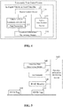
- Fig. 7 shows a schematic structural view of the active identification device 120 according to an embodiment of the present disclosure.
- the active identification device 120 of an embodiment of the present disclosure may comprise at least one of an image identification module 121 and a lidar identification module 122.
- the image identification module 121 is for capturing a front image during operation of the present train and determining whether there is an obstacle in front of the operation based on the front image and the preset track template image. When it is determined that there is an obstacle, the image identification module 121 determines a first distance between the obstacle and the train based on pixel position of the obstacle in the front image and pre-set mapping relationship between pixel position and distance.
- the lidar identification module 122 is for obtaining scene image in front of the train operation by a lidar, and determining whether there is an obstacle in front of the operation of the train according to the scene image and the preset digital scene map along the track. In case that an obstacle is determined as being exist, a second distance between the obstacle and the train is determined through the lidar.
- the image identification module 121 captures the front image of the present train during train operation according to a pre-set time interval, and identifies obstacle(s) in the image to obtain the distance between the obstacle and the train. Wherein an image identification algorithm may be selected according to the actual application needs.
- the image identification algorithm may be an image identification algorithm based on semantic segmentation, and the algorithm can realize detection and visibility calculation of an obstacle in front of the train operation (i.e., calculating distance between the train and the obstacle).
- an operation scene model of an scene image of train operation track is established based on deep learning so as to obtain a series of track template images; and a mapping relationship between pixel position of image and actual distance is established according to the distance between head end of the train and the position of the actual scene corresponding to the pixel position in the template image.
- it is identified whether there is an obstacle in the front image by comparing the front image acquired during train operation with the track template image obtained from modeling.
- a first distance between the obstacle and the present train is determined according to pixel position of the obstacle in the front image and mapping relationship between the above pixel position and distance.
- the lidar identification module 122 is implemented using lidar imaging and pulse signal ranging.
- the digital scene map along the track is obtained by the following steps: controlling a train to run throughout the whole operation route (i.e., track); collecting scene data in front of the train by a lidar mounted on the train; completing route feature identification and model for the entire route according to the collected scene data through deep learning; and forming a digital map through deep learning. That is, the digital scene map is obtained by collecting date of actual operation route modeling of the collected actual data. Wherein the collected data is real-time route data indicating that there is no obstacle on the operation route, and based on the digital map, an actual scene in which there is obstacle is not present in the train operation route is capable of being learnt.
- the actual scene may be that there is an object in certain location on the route (e.g., a semaphore or other device), with another object in another location on the route (e.g., poles).
- location of the present train may be learnt through the digital scene map without location information of Automatic Train Protection (ATP).
- ATP Automatic Train Protection
- identification result transmitted from the active identification device 120 to the master control device 130 is the identification result of the image identification module 121, and the distance contained in the identification result is the first distance.
- the identification result transmitted from the active identification device 120 to the master control device 130 is the identification result of the lidar identification module 122, and the distance contained in the identification result is the second distance.
- the active identification device 120 preferably comprises both the image identification module 121 and the lidar identification module 122.
- identification result transmitted by the active identification device 120 to the master control device 130 comprises both identification result of the image identification module 121 and identification result of the lidar identification module 122.
- the master control device 130 is configured to: calculate a second MA of the present train based on the second distance in case that a difference between the first distance and the second distance is less than a first pre-set distance, and calculate the second MA of the present train based on the smaller one between [00104] the first distance and the second distance in case that the difference between the first distance and the second distance is not less than the first pre-set distance.
- the image identification module 121 is able to accurately identify an obstacle in front of the train operation route and calculate the first distance, it is easily influenced by external factors such as the environment and the weather. For example, in case of poor environment (e.g., rainy), the identification result would be greatly affected and thereby would be not accurate enough.
- the lidar identification module 122 performs obstacle identification and ranging based on a lidar, the ranging accuracy of which is higher than that of the image identification module 121; further, it would get less influenced by external factors such as the environment and the weather. Therefore, accuracy of obstacle identification could be effectively improved by combining the image identification module 121 and the lidar identification module 122, with respective advantages of the two being combined.
- the second MA of the present train is calculated with the second distance determined by the lidar identification module 122. If the difference between the first distance and the second distance is not less than the first pre-set distance, it can be determined that the obstacles identified by the two are likely not one same obstacle, then the second MA of the present train is calculated based on the smaller one of the first distance and the second distance, so as to ensure safety of train operation.
- the active identification device 120 may further comprise a millimeter-wave radar identification module 123, as shown in figure 7 .
- the millimeter-wave radar identification module 123 is for determining a third distance between the obstacle and the train by the millimeter-wave radar when the image identification module 121 or the lidar identification module 122 determines that an obstacle exists.
- the master control device 130 is configured to calculate the second MA of the present train in case that the difference between the first distance and the third distance is less than a second pre-set distance, or that the difference between the second distance and the third distance is less than a third pre-set distance.
- the millimeter-wave radar identification module 123 works based on a millimeter-wave radar, and measures an object in the front by pulse signals.
- the millimeter-wave radar has a phased array antenna, it calculates straight-line distance between the obstacle and the radar and angle ⁇ between transmitted beam and the direction in which the train runs directly based on the speed of light and round-trip time of a directional narrow beam between the obstacle and the radar, as shown in figure 8 . After calculating above-mentioned straight-line distance and angle ⁇ , vertical distance and horizontal distance between the train and the obstacle may be further determined, so as to obtain accurate position of the obstacle (indicated by the black dot in the figure).
- the image identification unit 13 is also used to identify train track type in the first front image and train track type in the second front image and transmit the track type identification result to the master control device 130, wherein train track type comprises single track or turnout.
- the identification result filtering rule comprises the following items.
- the fourth distance is determined as the first distance.
- the fifth distance is determined as the first distance.
- the distance between the obstacle determined based on the front image corresponding to the turnout and the train is determined as the first distance.
- identification result of the telephoto camera is employed; in case that the dual cameras identify a turnout scene, identification result of the wide-angle camera is employed; and in case that one of the dual cameras identifies a single track scene and the other identifies a turnout scene, identification result of the camera that identifies more track is employed.
- identification of train track type may use a large number of the track templates as standard training samples, characteristics of the train track may be extracted by the standard training, and the track type in the front image may be identified based on the characteristics.
- one or two sets of master control devices may be set on head and trail of a train respectively; in general, master control devices are implemented as secure computer. With redundancy configuration scheme, a train is enabled to operate properly even when one set of master control devices is in failure.
- the TCTCS provided in an embodiment of the present disclosure comprises other components necessary for the safety operation control system of a train.
- TCTCS in addition to an active identification device integrated in IVOC, a vehicle-vehicle communication device and a master control device for inter-train communication link, TCTCS according to an embodiment of the present disclosure comprises necessary component such as Intelligent Train Supervision (ITS) system, object controller (OC), train management center (TMC), data communication system (DCS) and so on.
- ITS Intelligent Train Supervision
- OC object controller
- TMC train management center
- DCS data communication system
- the IVOC of the an embodiment of the present disclosure further comprises a Man-Machine Interface (MMI) module, a Balise Transmission Module (BTM), an Intelligent Train Operation (ITO) subsystems, and etc.
- MMI Man-Machine Interface
- BTM Balise Transmission Module
- ITO Intelligent Train Operation
- the vehicle-vehicle communication device, the active identification device and the master control device may be integrated into an Intelligent Train Protection (ITP) subsystem of the IVOC.
- ITP Intelligent Train Protection
- inter-train information exchange may be performed by a vehicle-vehicle communication device after current operation of the present train is determined by the operation information determining device; or it may be performed through the following items: a train obtains train list in the OC area by establishing a communication connection with trains within the list, and operation information (e.g., locations and operation speed, and etc.) is exchanged between the trains after the communication connection is established. Upon receiving train operation information in the current area, the train determines its adjacent train (the adjunct train in front capable of communication) based on location information of other trains and their location relationship with the train, to accomplish train selection, train in front identification and thereby protect the train from accident related to the train in front.
- a train obtains train list in the OC area by establishing a communication connection with trains within the list, and operation information (e.g., locations and operation speed, and etc.) is exchanged between the trains after the communication connection is established.
- operation information e.g., locations and operation speed, and etc.
- IVOC combined with the active identification device monitors train as well as other obstacles in front in real time, so as to ensure speed protection of the train.
- IVOC may take form of modular design, train head and tail can be configured with two sets of double 2-vote-2 safety computer platform, or a single set of platform.
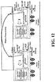
- Figure 12 shows a schematic diagram of a practical application scenario of vehicle on-board controller centered train operation control system according to a preferred embodiment of the present disclosure.
- the camera of the image identification module of the active identification device, the lidar of the lidar identification module, and the millimeter-wave radar of the millimeter-wave radar identification module are all installed in head of the train.
- a fill light(s) may also be set to improve accuracy of active identification in case of poor light.
- a train may be controlled by a crash handler in the presence of an obstacle for in-time braking.
- the train is also equipped with a speed and position detection module, the module measure speed based on inertial navigation system, speed sensor (test positioning as shown in the figure), inertial navigation, it uses satellite, ground transponder and speed integration to achieve independent positioning of a train
- the master control device of the present embodiment may be implemented directly using an industrial pad.
- the system may take form of modular design, and define standard speed interface, so that the system supports different speed program access, without the need to change interface and speed detection module when speed sensor changes.
- a communication processor automatically controls vehicle-vehicle and vehicle-ground communication.
- Functional blocks shown in block diagrams described above may be implemented as hardware, software, firmware, or a combination thereof.
- it When implemented in hardware, it may be, for example, electronic circuits, application specific integrated circuits (ASICs), suitable firmware, plug-ins, function trains, and the like.
- ASICs application specific integrated circuits
- elements of the present disclosure are programs or code segments that are used to perform the desired tasks.
- the program or code segment may be stored in a machine-readable medium or transmitted over a transmission medium or a communication link through a data signal carried in carriers.
- Machine-readable media may comprise any medium capable of storing or transmitting information.
- machine-readable media comprise electronic circuits, semiconductor memory devices, ROM, flash memory, erasable ROM (EROM), floppy disks, CD-ROMs, optical disks, hard disks, optical media, radio frequency (RF) links, and the like.
- the code segments may be downloaded via a computer network such as the Internet, an intranet, or the like.
Landscapes
- Engineering & Computer Science (AREA)
- Mechanical Engineering (AREA)
- Physics & Mathematics (AREA)
- General Physics & Mathematics (AREA)
- Radar, Positioning & Navigation (AREA)
- Remote Sensing (AREA)
- Life Sciences & Earth Sciences (AREA)
- Atmospheric Sciences (AREA)
- Mathematical Physics (AREA)
- Train Traffic Observation, Control, And Security (AREA)
- Electric Propulsion And Braking For Vehicles (AREA)
Description
- The present disclosure relates to the field of rail transportation, and more particularly, to a vehicle on-board controller centered train operation control system.
- Communication-based Train Control (CBTC) uses communication media for two-way communication between a train and ground equipment, as a replacement for track circuit for medium achieving train operation control.
- Traditional CBTC system concentrates on ground control. A train is registered with a Zone Controller (ZC), under control of the ZC, and take the initiative to report to the ZC. ZC calculates the movement authority (MA) for trains within its managing scope, it realizes interaction of vehicle-ground information through continuous vehicle-ground two-way wireless communication, and tracks operation under target-distance based mobile blocking system. However, traditional CBTC systems need a plurality of devices and have complex interfaces, with huge amount of data exchange. Further, because of presence of delays in the transmission of vehicle-ground transmission, instantaneity of a system is limited, as well as train operation control flexibility and intelligence level.
- Due to the shortcomings in a traditional CBTC system and for high safe and efficient operation requirements of a rail transit system, vehicle-vehicle communication based CBTC system rose in response. A vehicle-vehicle communication based CBTC system reduces the number of ground devices, and uses a Vehicle on-board controller (VOBC) as it core. Based on direct communications between trains, a train directly obtains information about vehicles in front or behind it (e.g. train location and speed), it control the speed of the train to prevent collision or rear-end, to make more flexible control of the train so as to improve its the operational efficiency.
- However, a vehicle- vehicle communication based CBTC system depends on direct communications between trains, once there is a train without communication equipment or with equipment failure operation in front, the train is unable to learn the operation information that there are other trains in front, causing wrong MA of the train, and therefore resulting in serious danger. In addition, if an obstruction appears in front of the train (e.g., accidental intrusion of objects, or other vehicles stops on the train tracks temporary, or trees or other obstructions on the tracks due to extreme weather), existing vehicle-vehicle communication based CBTC system cannot identify obstacles, so that the train cannot stop in time, causing danger for the train, and even worse, for passengers, an aftermath may be extremely serious.
- Document
WO 2016/022635 A1 discloses a positive train control system for a moving block system which uses an on-board controller and multiple sensors to detect an object on a track and control the train based thereon to avoid collisions. - The current invention provides a vehicle on-board controller centered train operation control system as defined in claim 1. With such system, rear-end accidents may be prevented effectively and safety of train operation may be improved.
- According to the invention a vehicle on-board controller centered train operation control system is provided the control system comprising an intelligent vehicle on-board controller (IVOC) provided on respective trains, the IVOC comprises a vehicle-vehicle communication device, an active identification device and a master control device.
- The vehicle-vehicle communication device is configured to exchange information between trains and obtaining current operation information of other trains, and transmit current operation information of the other trains to the master control device. Wherein the current operating information comprises but is not limited to current position, direction and speed of operation of the train.
- The active identification device is for determining whether an obstacle exists in front of the train. In case that it is determined that an obstacle exists, the distance between the obstacle and the train is determined and an identification result is transmitted to the master control device. Wherein the identification result comprises a determination result and a distance between the obstacle and the vehicle when existence of the obstacle is determined. Wherein recognizable distance of the active identification device is greater than the emergency braking moving distance of the present train and is not greater than the minimum safe operation distance between adjacent trains.
- The master control device is configured to receive the current operation information of other trains transmitted by the vehicle-vehicle communication device, and the identification result transmitted by the active identification device; determine the adjacent train in front capable of communication based on current operation information of the present train and current operation information of other trains, calculate a first MA based on the current operation information of the train and the current operation information of the adjacent train in front capable of communication. In case that the identification result indicates that there is no obstacle, the first MA is determined as final MA of the present train. In case that the identification result indicates that there is an obstacle, a second MA is determined according to a distance in the identification result, the final MA of the present train is determined based on the first MA and the second MA.
- Further, as described above, the master control device is configured to determine the second MA as the final MA in case that a running end of the first MA is in front of a running end of the second MA, and to determine the first MA or the second MA as the final MA in case that the running end of the second MA is in front of the running end of the first MA.
- Further, the control system as described above, may further comprise: an operation information determining device configured to determine current operation information of the present train and transmitting the current operation information of the present train to the vehicle-vehicle communication apparatus and the master control device.
- The vehicle-vehicle communication device may comprise a data transceiver configured to broadcast the current operation information of the present train and receive current operation information of other trains broadcasted by the other trains.
- Further, in the control system as described above, the data transceiver comprises a data radio.
- Further, in the control system as described above, the operation information determining device may comprise an RFID reader, an accelerometer, and an operation information determining module provided on the train, and RFID tags are disposed on train operation track at a predetermined interval.
- The RFID reader is configured to read tag information of the RFID tags passed by train operation, and the tag information comprises the tag position information and tag reading time.
- The accelerometer is configured to detect current operation acceleration of the present train.
- The operation information determining module is configured to determining current position and the operation direction of the present train based on the tag information, and calculate current operation speed of the present train based on operation speed at a previous time and the current operation acceleration.
- Further, in an embodiment of the control system as described above, the operation information determining device further comprises an operation state determining module provided on the train.
- The operation state determining module is configured to determine operation state of the present train when the operation acceleration is zero, and the operation state is either constant motion or stationary.
- The operation information determining module is further configured to determine current operation speed of the present train as operation speed at a previous time in case that the operation state is constant motion, and to determine the current operation speed of the present train as zero in case that the operation state is stationary.
- Further, in an embodiment of the control system as described above, the active identification device comprises at least one of the following modules.
- An image identification module is configured to capture a front image during operation of the present train and determine whether there is an obstacle in front of the operation based on the front image and the preset track template image. When it is determined that there is an obstacle, the image identification module determines a first distance between the obstacle and the train based on pixel position of the obstacle in the front image and pre-set mapping relationship between pixel position and distance.
- A lidar identification module is configured to obtain scene image in front of the train operation by a lidar, and determine whether there is an obstacle in front of the operation of the train according to the scene image and the preset digital scene map along the track. In case that an obstacle is determined as being exist, a second distance between the obstacle and the train is determined through the lidar.
- Further, in the control system as described above, when the active identification device comprises the image identification module and the lidar identification module as described above, the master control device is configured to: calculate a second MA of the present train based on the second distance in case that a difference between the first distance and the second distance is less than a first pre-set distance, and calculate the second MA of the present train based on the smaller one between the first distance and the second distance in case that the difference between the first distance and the second distance is not less than the first pre-set distance.
- Further, in the control system as described above, the active identification device further comprises: a millimeter-wave radar identification module configured to a third distance between the obstacle and the train by the millimeter-wave radar when the image identification module or the lidar identification module determines that an obstacle exists and the master control device is configured to calculate the second MA of the present train in case that the difference between the first distance and the third distance is less than a second pre-set distance, or that the difference between the second distance and the third distance is less than a third pre-set distance.
- Further, in an embodiment of the control system as described above, the image identification module comprises a first image capturing unit and a second image capturing unit, the first image capturing unit and the second image capturing unit are respectively connected to the image identification unit,
- The master control device is further configured to control the first image capturing unit and the second image capturing unit to capture images synchronically.
- The first image capturing unit is configured to capture a first front image in during the train operation.
- The second image capturing unit is configured to capture a second front image in during the train operation.
- An image identification unit is configured to determine whether there is an obstacle in front of the operation route according to the first front image and a pre-set first track template image. In case that there is an obstacle, a fourth distance between the obstacle and the train is determined based on a first mapping relationship between distance and pixel position in the first front image to obtain a first identification result. The image identification unit is further configured to determine whether there is an obstacle in front of the operation route according to the second front image and a pre-set second track template image. In case that there is an obstacle, a fifth distance between the obstacle and the train is determined based on a second mapping relationship between distance and pixel position in the second front image to obtain a second identification result. The first identification result and second identification result are sent to the master control device.
- The master control device further determines the distance contained in the identification result that indicates there is an obstacle as a first distance in case that only one of the first identification result and the second identification result indicates an obstacle; and select the first distance from the fourth distance and the fifth distance according to predetermined identification result selection rules in case that both the first identification result and the second identification result indicate obstacles.
- Further, in an embodiment of the control system as described above, the first image capturing unit is a telephoto camera, and the second image capturing unit is a wide angle camera.
- Further, in an embodiment of the control system as described above, the image identification unit also identifies the number of train track lines in the first front image and train track type in the second front image, and transmits the track type identification result to the master control device, and divides train track types into single track or turnout.
- If the train track type in the first front image and the train track type in the second front image are both single tracks, then the fourth distance is determined as the first distance.
- If the train track type in the first front image and the train track type in the second front image are both turnouts, the fifth distance is determined as the first distance.
- If the train track type in the first front image and the train track type in the second front image are different types, then the distance between the obstacles determined based on the front image corresponding to the turnout and the train is determined as the first distance.
- The present invention provides a vehicle on-board controller centered train operation control system. The control system combines current operation information of the other trains obtained by the vehicle-vehicle communication device and identification result for obstacles in front of operation route obtained of the active identification device, to finally determine MA for a train. With such control system, rear-end train or more serious accidents may be avoided in case that there is a train without communication equipment or with equipment failure operation in front, or an obstruction impeding train operation appears in front of the train. Further, the control system provided by embodiments of the present disclosure enables a train to operate with a relatively high speed under the premise of safe operation, and improves operation efficiency and reliability.
- Other features, objects, and advantages of the present disclosure will become more apparent from a reading of the following detailed description of a non-limiting example with reference to the accompanying drawings in which like or similar reference numerals refer to like or similar features.
-
Figure 1 is a schematic diagram of a vehicle on-board controller centered train operation control system in an embodiment of the present disclosure; -
Figure 2 is a schematic diagram of a specific application scenario of a train operation control system according to an embodiment of the present disclosure; -
Figure 3 is a schematic view of another specific application scenario of a train operation control system according to an embodiment of the present disclosure; -
Figure 4 is a schematic diagram of a vehicle on-board controller centered train operation control system in another embodiment of the present disclosure; -
Figure 5 is a schematic structural view of an operation information determining device according to an embodiment of the present disclosure; -
Figure 6 is an arrangement diagram of RFID tags of an operation information determining device in an application scenario according to an embodiment of the present disclosure; -
Figure 7 is a schematic structural view of an active identification device in an embodiment of the present disclosure; -
Figure 8 is a schematic diagram of a millimeter-wave radar identification module positioning obstruction in an embodiment of the present disclosure; -
Figure 9 is a schematic diagram of the structure of an image identification module in an embodiment of the present disclosure; -
Figure 10 is a schematic view of the line-of-sight range of the telephoto camera and the wide-angle camera in an embodiment of the present disclosure; -
Figure 11 is a schematic diagram of a vehicle on-board controller centered train operation control system in a particular embodiment of the present disclosure; and -
Fig. 12 is a schematic view showing a practical scenario of a vehicle on-board controller centered train operation control system in a particular embodiment of the present disclosure. - Features and exemplary embodiments of various aspects of the present disclosure will be described in detail below. In the following detailed description, numerous specific details are set forth in order to provide a thorough understanding of the present disclosure. It will be apparent, however, to a person skilled in the art that the present disclosure may be practiced without the need for some of the details in these specific details. The following description of the embodiments is merely for the purpose of providing a better understanding of the present disclosure by showing examples of the present disclosure. The present disclosure is by no means limited to any of the specific configurations and algorithms set forth below, but is intended to cover any modifications, substitutions, and improvements of elements, components and algorithms, without departing from scope of the apended claims. In the drawings and the following description, well-known structures and techniques are not shown, in order to avoid unnecessarily obscuring the present disclosure.
- Current vehicle-vehicle communication based CBTC system mainly exchanges information with IVOC of trains in front of and behind it, Object Controller (OC) and intelligent Train monitoring (ITS) system using IVOC installed thereon, to achieve independent calculation of MA of the train. Vehicle-vehicle communication based CBTC system not only greatly reduces the construction and maintenance costs of railside equipment, but also has a more flexible control of train intervals, thereby enhancing operational efficiency of trains. However, a vehicle-vehicle communication based CBTC system depends on the direct communication between trains; once there is a train without communication equipment or with equipment failure operation in front, or an obstruction impeding train operation appears in front of the train, the train is unable to obtain MA correctly, and therefore resulting in serious danger. Therefore, a more comprehensive and safer train operation control system is required.
-
Figure 1 shows a schematic diagram of a Train-centric Train Control System (TCTCS) with an IVOC as a core provided in an embodiment of the present disclosure. As shown inFigure 1 , the TCTCS of an embodiment of the present disclosure comprises an Intelligent Vehicle on-board controller (IVOC) 100 provided on each train, and theIVOC 100 comprises a vehicle-vehicle communication device 110, anactive identification device 120, and amaster control device 130. - The vehicle-
vehicle communication device 110 is for information exchange between trains and obtaining current operation information of other trains, and transmitting current operation information of the other trains to themaster control device 130. Wherein the current operating information comprises but is not limited to current position, direction and speed of operation of the train. - The
active identification device 120 is for determining whether an obstacle exists in front of the train. In case that it is determined that an obstacle exists, the distance between the obstacle and the train is determined and an identification result is transmitted to themaster control device 130. Wherein the identification result comprises a determination result and a distance between the obstacle and the vehicle when existence of the obstacle is determined. Wherein recognizable distance of theactive identification device 120 is greater than the emergency braking moving distance of the present train and is not greater than the minimum safe operation distance between adjacent trains. - The master control device is 130 for receiving the current operation information of other trains transmitted by the vehicle-
vehicle communication device 110, and the identification result transmitted by theactive identification device 120; determining the adjacent train in front capable of communication based on current operation information of the present train and current operation information of other trains, calculating a first MA based on the current operation information of the train and the current operation information of the adjacent train in front capable of communication. In case that the identification result indicates that there is no obstacle, the first MA is determined as final MA of the present train. In case that the identification result indicates that there is an obstacle, a second MA is determined according to a distance in the identification result, the final MA of the present train is determined based on the first MA and the second MA. - In the TCTCS provided by an embodiment of the present disclosure, the 0
communication device 110 and theactive identification device 120 are integrated in theIVOC 100 simultaneously. Calculation of MA of train is no longer dependent solely on communication between the trains, but rather the integrated judgment and determination of the train MA is realized by combination of the vehicle-vehicle communication device 110 and theactive identification device 120. Specifically, in case that identification result of theactive identification device 120 indicates that there is no obstacle, it indicates that there is no obstacle affecting train operation within recognizable distance of theactive identification device 120; further, since the recognizable distance of theactive identification device 120 is greater than that the first MA, the first MA (which is calculated based on the vehicle-vehicle communication device 110) can be directly used as the final MA of the train. Theactive identification device 120 serves as an auxiliary device of the TCTCS, this avoids the situation that an emergency braking cannot be performed when an obstacle appears within recognizable distance of theactive identification device 120. It avoids the occurrence of danger, as well as ensures efficiency of train operation. - When identification result of the
active identification device 120 is that an obstacle exists, it is necessary to determine a final MA of the train comprehensively based on the first MA (which is calculated by the vehicle-vehicle communication device 110) and the second MA (which is calculated by the active identification device 120) according to actual application scenarios, so as to ensure safety of train operation. - In an embodiment of the present disclosure, an obstacle comprises other trains that affect the safe operation of the present train and/or other objects that impede safe operation of the present train, for example, a fault train in front of the present train, other equipment parked on or aside of the track, a tree fallen on the track, and so on.
- In accordance with the current invention, an adjacent train in front of the present train identified by the
master control device 130 based on the information transmitted from the vehicle-vehicle communication device 110 refers to an adjacent train that runs in front of the present train, with vehicle-vehicle communication device is installed that works properly. Such adjacent train may not be literary the adjacent train, because that a true "adjacent train" may not installed with vehicle-vehicle communication device or its vehicle-vehicle communication device may be in malfunction. Under this circumstance, themaster control device 130 cannot recognize the true adjacent train based on the vehicle-vehicle communication device. Therefore, in an embodiment of the present disclosure, a train in front of the present train that is identified by themaster control device 130 based on the vehicle-vehicle communication device 110 refers to "a train in front capable of communication". - It is to be noted that in an embodiment of the present disclosure, recognizable distance of the
active identification device 120 refers to a straight line recognizable distance. That is, recognizable distance is the distance between ahead of a train and the maximum distance in front of the train that is recognizable for theactive identification device 120.. - In accordance with the current invention, the recognizable distance of the
active identification device 120 is greater than emergency braking running distance (i.e., the distance that a train would keep running after an emergency braking) of the present train. In case that an obstacle is found in front of a train and an emergency braking is required, it eliminates the possibility of collision or rear-end with the obstacle even after the emergency braking. Recognizable distance of theactive identification device 120 is not greater than the minimum safe operation distance between adjacent trains (i.e., train tracking operation interval), which may effectively reduce the number of times that the second MA is calculated, thereby save system resources. - With TCTCS of an embodiment of the present disclosure, a safe and reasonable MA is provided for a train though combination of the vehicle-
vehicle communication device 110 and theactive identification device 120. It improves safety of the train and ensure safe operation of the train, and ensures the operation efficiency of the train at the same time, which better meets the practical needs. - In accordance with the current invention, the
master control device 130 is configured to determine the second MA as the final MA in case that a running end of the first MA is in front of a running end of the second MA, and to determine the first MA or the second MA as the final MA in case that the running end of the second MA is in front of the running end of the first MA. - In practice, if the
active identification device 120 determines that there is an obstacle in the front, and that a running end of the MA calculated based on identification result of theactive identification device 120 is behind a running end of the MA calculated by the vehicle-vehicle communication device 110, current MA for the present train is determined according to the identification result of the active identification device 120 (that is, determining the second MA as the final MA), so as to avoid collision accident caused by operations according to the first MA; so as to ensure safe operation of the train. If theactive identification device 120 determines that there is an obstacle in the front, and that a running end of the MA calculated based on identification result of theactive identification device 120 is in front of a running end of the MA calculated by the vehicle-vehicle communication device 110, it is indicated that there is no operational obstacle within the distance to the run end of the second MA, and either the first MA or the second MA may serve as the final MA. In practice, it is preferable to determine the second MA as the final MA. Because that when the second MA serves as the final MA, current operation speed of the train may be accelerated according to the MA. It ensures safety of train operation while improve efficiency thereof. - It should be noted that, in an embodiment of the present disclosure, the phases "the front" or "behind" are relative concept with respect to moving direction of the train.
-
Figure 2 shows a particular application scenario in an embodiment of the present disclosure, wherein on left side of is the present train, the two long parallel lines in the figure are two operating tracks, and each circle on the tracks represents a train station; Q1, Q2, Q3 said inter-station sections. In a particular embodiment, the present train is running on section Q1, and the unidirectional arrow in the figure indicates that the operation direction of the present train is from left to right; and point A is the current running end of the first MA (i.e., the running end of the MA calculated by the vehicle-vehicle communication device 110); and L1 is the current safe operation distance of the train corresponding to the first MA. The identification result of theactive identification device 120 is that there is no obstacle, and point B is the end of the recognizable distance of the active identification device 120 (i.e., L2 is the recognizable distance of the active identification device 12). Under this circumstance, the first MA calculated based on the vehicle-vehicle communication device 110 serves as the final MA; and theactive identification device 120 serves as the safe operation auxiliary device. Since there is no obstacle within the recognizable distance, it is possible to accelerate operation speed of the train appropriately within the range of the recognizable distance, so to ensure safe operation and as well as improve operation speed. With the scheme of the particular embodiment, operation speed of a train at a bend could be greatly accelerated. It is possible to solve the problem in existing art that the operation speed of the train at a bend need to be reduced greatly, which leads to low efficiency of train operation. -
Figure 3 shows another application scenario in an embodiment of the present disclosure. In the particular embodiment, the present train is running on section Q1, point C is the current running end of the first MA of the train, and point D is the current running end of the second MA; the point D is in front of the point C (i.e., the running end of the MA calculated by theactive identification device 120 is in front of the running end of the MA calculated by the vehicle-vehicle communication device 110). Thus under this circumstance, the second MA calculated by theactive identification device 120 can directly serve as the current final MA, and operation distance corresponding to such MA is greater than that of the MA calculated by the vehicle-vehicle communication device 110. Therefore, current operation speed of the train may be accelerated appropriately on basis of the operation speed of the second MA, so as to improve efficiency of train operation. - As can be seen from the actual application scenarios shown in
Figures 2 and 3 , the TCTCS provided by embodiments of the present disclosure is based on two different mobile authorization calculation schemes, which enable a train to operate with a relatively high speed under the premise of safe operation, and improve operation efficiency and reliability. - In TCTCS according to an embodiment of the present disclosure, the
active identification device 120 is added on basis of mobile authorization calculation realized based on vehicle-vehicle communication, and the determination of the final MA of a train is realized by combination of the he vehicle-vehicle communication device 110 and theactive identification device 120 together. For such a control system, in addition to improve safety of train tracking operation, it also improve operation efficiency of a train by combining actual calculation results of both the vehicle-vehicle communication device 110 and theactive identification device 120, and is more in line with the practical application requirements. In case that there is a failure in vehicle-vehicle communication device or that there is an obstacle in operation track in the front, it may effectively prevent the train rear-end or collision accident, and better protect safety and reliability of train operation. - In an embodiment of the present disclosure, the TCTCS further comprises an operation
information determining device 140, and the vehicle-vehicle communication device 110 comprises adata transceiver 111, as shown infigure 4 . - The operation
information determining device 140 is for determining current operation information of the present train and transmitting the current operation information of the present train to the vehicle-vehicle communication apparatus 110 and themaster control device 130. - A
data transceiver 111 is for broadcasting the current operation information of the present train and receiving current operation information of other trains broadcasted by the other trains. - In an embodiment of the present disclosure, the
data transceiver 111 is preferably a data radio. - A data radio (also known as wireless data transmission station) is a high-performance professional data transmission station utilizing digital signal processing technology and software radio technology, with features such as reliable data transmission, low cost, easy installation and maintenance, wide cover range and so on; it is suitable for a plurality of wildly distributed points, complex geographical environment and other occasions. Therefore, use of data radio can be a good way to ensure inter-train data transmission in the scene of train operation, it broadcasts the train's position, direction of operation, operation speed and other operational information and receives digital communication from other trains capable of communication within scope of the data radio. Data radio obtains current operation information of other trains, and provides the
master control device 130 with data for calculating the first MA. - In an embodiment of the present disclosure, the operation
information determining device 140 may comprise anRFID reader 141, anaccelerometer 142, and an operationinformation determining module 143 provided on the train, and RFID tag(s) 144 is disposed on train operation track at a predetermined interval, as shown inFigure 5 . - The
RFID reader 141 is for reading tag information of the RFID tags passed by train operation, and the tag information comprises the tag position information and tag reading time. - The
accelerometer 142 is for detecting current operation acceleration of the present train. - The operation
information determining module 143 is for determining current position and the operation direction of the present train based on the tag information, and calculating current operation speed of the present train based on operation speed at a previous time and the current operation acceleration. - In practice, the
RFID tag 144 may be arranged according to axle counter principle to locations such as entrance and exit of station, the inter-station, the turnout and the like. TheRFID reader 141 may be mounted at the bottom of a train, and the tag information of theRFID tag 144 is read by the train during operation. Since mounting position ofrespective RFID tag 144 is fixed, theRFID reader 141 may basically determine location of a train by reading location information of theRFID tag 144 within communication range of RFID tag. Operation direction of a train may be determined based on the positions of thedifferent RFID tag 144 read by theRFID reader 141 during train operation and the times of reading tags. The above-described train operationinformation determining device 140 provided by an embodiment of the present disclosure is simple and highly available. - In the application scenario shown in
Fig. 6 , I and II represent the two directions of subway, and the black circle in the figure indicates the RFID tags 144 of the two stations of station A and station B. During train operation theRFID reader 141 firstly readsRFID tag 144 of the B station and then readsRFID tag 144 of the station A, thus the operation direction of the train is determined as from B to A (i.e., as shown by the arrow in the figure). - In an embodiment of the present disclosure, the
accelerometer 142 may measure the acceleration value of train operation when the train is operation at variable speed, and calculate current operation speed of the train based on current acceleration value and operation speed at a previous time (the initial speed at which the current operation speed is calculated). - In an embodiment of the present disclosure, the operation
information determining device 140 further comprises an operationstate determining module 145 provided on the train, as shown infigure 5 . - The operation
state determining module 145 is used to determine operation state of the present train when the operation acceleration is zero, and the operation state is either constant motion or stationary. - The operation
information determining module 143 is also used to determine current operation speed of the present train as operation speed at a previous time in case that the operation state is constant motion, and to determine the current operation speed of the present train as zero in case that the operation state is stationary. - In actual application scenario, the train may be operation at a constant speed or stationary during operation process, under such circumstance, measurement result of the
accelerometer 142 is zero. Therefore, it is necessary to firstly determine whether the operation state of a train is constant motion or stationary, and then determine current operation speed of the train according to the operation state of the train. In an embodiment of the present disclosure, the operationstate determining module 145 may be implemented as an optical flow camera, or train motion trends may be determined by a lidar (using Doppler Effect). The optical flow camera mainly utilizes feature points in successive pictures captured by itself, compares whether there is a change in vertical and horizontal pixels of feature points location of the successive pictures. If there is a change, the motion trend is determined as motion; otherwise it is determined as stationary. Lidar uses Doppler Effect to determine movement of the train trend. -
Fig. 7 shows a schematic structural view of theactive identification device 120 according to an embodiment of the present disclosure. As shown infigure 7 , theactive identification device 120 of an embodiment of the present disclosure may comprise at least one of animage identification module 121 and alidar identification module 122. - The
image identification module 121 is for capturing a front image during operation of the present train and determining whether there is an obstacle in front of the operation based on the front image and the preset track template image. When it is determined that there is an obstacle, theimage identification module 121 determines a first distance between the obstacle and the train based on pixel position of the obstacle in the front image and pre-set mapping relationship between pixel position and distance. - The
lidar identification module 122 is for obtaining scene image in front of the train operation by a lidar, and determining whether there is an obstacle in front of the operation of the train according to the scene image and the preset digital scene map along the track. In case that an obstacle is determined as being exist, a second distance between the obstacle and the train is determined through the lidar. - The
image identification module 121 captures the front image of the present train during train operation according to a pre-set time interval, and identifies obstacle(s) in the image to obtain the distance between the obstacle and the train. Wherein an image identification algorithm may be selected according to the actual application needs. - In a particular embodiment of the present disclosure, the image identification algorithm may be an image identification algorithm based on semantic segmentation, and the algorithm can realize detection and visibility calculation of an obstacle in front of the train operation (i.e., calculating distance between the train and the obstacle). In particular, an operation scene model of an scene image of train operation track is established based on deep learning so as to obtain a series of track template images; and a mapping relationship between pixel position of image and actual distance is established according to the distance between head end of the train and the position of the actual scene corresponding to the pixel position in the template image. In a process of identifying the actual train operation, it is identified whether there is an obstacle in the front image by comparing the front image acquired during train operation with the track template image obtained from modeling. In case that an obstacle is identified, a first distance between the obstacle and the present train is determined according to pixel position of the obstacle in the front image and mapping relationship between the above pixel position and distance.
- The
lidar identification module 122 is implemented using lidar imaging and pulse signal ranging. In an embodiment of the present disclosure, the digital scene map along the track is obtained by the following steps: controlling a train to run throughout the whole operation route (i.e., track); collecting scene data in front of the train by a lidar mounted on the train; completing route feature identification and model for the entire route according to the collected scene data through deep learning; and forming a digital map through deep learning. That is, the digital scene map is obtained by collecting date of actual operation route modeling of the collected actual data. Wherein the collected data is real-time route data indicating that there is no obstacle on the operation route, and based on the digital map, an actual scene in which there is obstacle is not present in the train operation route is capable of being learnt. For example, the actual scene may be that there is an object in certain location on the route (e.g., a semaphore or other device), with another object in another location on the route (e.g., poles). During process of train operation, location of the present train may be learnt through the digital scene map without location information of Automatic Train Protection (ATP). Further, it is determined whether there is an obstacle in front of operation route according to learnt scene of the current location; if there is an obstacle that affects the operation of a train, the distance between the train and the obstacle (i.e., the second distance) is obtained by the lidar. - In case that the
active identification device 120 is theimage identification module 121, identification result transmitted from theactive identification device 120 to themaster control device 130 is the identification result of theimage identification module 121, and the distance contained in the identification result is the first distance. In case that theactive identification device 120 is thelidar identification module 122, the identification result transmitted from theactive identification device 120 to themaster control device 130 is the identification result of thelidar identification module 122, and the distance contained in the identification result is the second distance. - In an embodiment of the present disclosure, the
active identification device 120 preferably comprises both theimage identification module 121 and thelidar identification module 122. Under such circumstance, identification result transmitted by theactive identification device 120 to themaster control device 130 comprises both identification result of theimage identification module 121 and identification result of thelidar identification module 122. - Under such circumstance, the
master control device 130 is configured to: calculate a second MA of the present train based on the second distance in case that a difference between the first distance and the second distance is less than a first pre-set distance, and calculate the second MA of the present train based on the smaller one between [00104] the first distance and the second distance in case that the difference between the first distance and the second distance is not less than the first pre-set distance. - In the practice, although the
image identification module 121 is able to accurately identify an obstacle in front of the train operation route and calculate the first distance, it is easily influenced by external factors such as the environment and the weather. For example, in case of poor environment (e.g., rainy), the identification result would be greatly affected and thereby would be not accurate enough. On the other hand, thelidar identification module 122 performs obstacle identification and ranging based on a lidar, the ranging accuracy of which is higher than that of theimage identification module 121; further, it would get less influenced by external factors such as the environment and the weather. Therefore, accuracy of obstacle identification could be effectively improved by combining theimage identification module 121 and thelidar identification module 122, with respective advantages of the two being combined. - Specifically, if the difference between the first distance determined by the
image identification module 121 and the second distance determined by thelidar identification module 122 is less than the first set distance, it can be determined that the obstacle identified by the two is the same obstacle. Since the ranging accuracy of thelidar identification module 122 is higher than that of theimage identification module 121, the second MA of the present train is calculated with the second distance determined by thelidar identification module 122. If the difference between the first distance and the second distance is not less than the first pre-set distance, it can be determined that the obstacles identified by the two are likely not one same obstacle, then the second MA of the present train is calculated based on the smaller one of the first distance and the second distance, so as to ensure safety of train operation. - In an embodiment of the present disclosure, the
active identification device 120 may further comprise a millimeter-waveradar identification module 123, as shown infigure 7 . - The millimeter-wave
radar identification module 123 is for determining a third distance between the obstacle and the train by the millimeter-wave radar when theimage identification module 121 or thelidar identification module 122 determines that an obstacle exists. - Under such circumstance, the
master control device 130 is configured to calculate the second MA of the present train in case that the difference between the first distance and the third distance is less than a second pre-set distance, or that the difference between the second distance and the third distance is less than a third pre-set distance. - The millimeter-wave
radar identification module 123 works based on a millimeter-wave radar, and measures an object in the front by pulse signals. The millimeter-wave radar has a phased array antenna, it calculates straight-line distance between the obstacle and the radar and angle θ between transmitted beam and the direction in which the train runs directly based on the speed of light and round-trip time of a directional narrow beam between the obstacle and the radar, as shown infigure 8 . After calculating above-mentioned straight-line distance and angle θ, vertical distance and horizontal distance between the train and the obstacle may be further determined, so as to obtain accurate position of the obstacle (indicated by the black dot in the figure). - In an embodiment of the present disclosure, the
image identification unit 13 is also used to identify train track type in the first front image and train track type in the second front image and transmit the track type identification result to themaster control device 130, wherein train track type comprises single track or turnout. As such, the identification result filtering rule comprises the following items. - If the train track type in the first front image and the train track type in the second front image are both single tracks, then the fourth distance is determined as the first distance.
- If the train track type in the first front image and the train track type in the second front image are both turnouts, the fifth distance is determined as the first distance.
- If the train track type in the first front image and the train track type in the second front image are different types (that is, one is a single track and the other is a turnout), the distance between the obstacle determined based on the front image corresponding to the turnout and the train is determined as the first distance.
- In other words, in case that dual cameras (i.e., a telephoto camera and a wide-angle camera) identify a single track scene, identification result of the telephoto camera is employed; in case that the dual cameras identify a turnout scene, identification result of the wide-angle camera is employed; and in case that one of the dual cameras identifies a single track scene and the other identifies a turnout scene, identification result of the camera that identifies more track is employed. Wherein identification of train track type may use a large number of the track templates as standard training samples, characteristics of the train track may be extracted by the standard training, and the track type in the front image may be identified based on the characteristics.
- In practice, one or two sets of master control devices may be set on head and trail of a train respectively; in general, master control devices are implemented as secure computer. With redundancy configuration scheme, a train is enabled to operate properly even when one set of master control devices is in failure.
- It should be noted that in addition to the above-described components clearly described in embodiments of the present disclosure, the TCTCS provided in an embodiment of the present disclosure comprises other components necessary for the safety operation control system of a train. As shown in
figure 11 , in addition to an active identification device integrated in IVOC, a vehicle-vehicle communication device and a master control device for inter-train communication link, TCTCS according to an embodiment of the present disclosure comprises necessary component such as Intelligent Train Supervision (ITS) system, object controller (OC), train management center (TMC), data communication system (DCS) and so on. In addition, in practice the IVOC of the an embodiment of the present disclosure further comprises a Man-Machine Interface (MMI) module, a Balise Transmission Module (BTM), an Intelligent Train Operation (ITO) subsystems, and etc. The vehicle-vehicle communication device, the active identification device and the master control device may be integrated into an Intelligent Train Protection (ITP) subsystem of the IVOC. - For a TCTCS according to an embodiment of the present disclosure, inter-train information exchange may be performed by a vehicle-vehicle communication device after current operation of the present train is determined by the operation information determining device; or it may be performed through the following items: a train obtains train list in the OC area by establishing a communication connection with trains within the list, and operation information (e.g., locations and operation speed, and etc.) is exchanged between the trains after the communication connection is established. Upon receiving train operation information in the current area, the train determines its adjacent train (the adjunct train in front capable of communication) based on location information of other trains and their location relationship with the train, to accomplish train selection, train in front identification and thereby protect the train from accident related to the train in front. IVOC combined with the active identification device monitors train as well as other obstacles in front in real time, so as to ensure speed protection of the train. IVOC may take form of modular design, train head and tail can be configured with two sets of double 2-vote-2 safety computer platform, or a single set of platform.
-
Figure 12 shows a schematic diagram of a practical application scenario of vehicle on-board controller centered train operation control system according to a preferred embodiment of the present disclosure. As shown infigure 12 , according to the present embodiment, the camera of the image identification module of the active identification device, the lidar of the lidar identification module, and the millimeter-wave radar of the millimeter-wave radar identification module are all installed in head of the train. In order to improve identification effect of the identification modules, a fill light(s) may also be set to improve accuracy of active identification in case of poor light. With the result of identification of the active identification device, a train may be controlled by a crash handler in the presence of an obstacle for in-time braking. When there is a train incapable of communication in the route, and that the distance between the train incapable of communication and the present train is relative long, operation speed of the present train may be ensured and the overall operation efficiency of the system may be improved. The train is also equipped with a speed and position detection module, the module measure speed based on inertial navigation system, speed sensor (test positioning as shown in the figure), inertial navigation, it uses satellite, ground transponder and speed integration to achieve independent positioning of a train The master control device of the present embodiment may be implemented directly using an industrial pad. For the train speed detection, the system may take form of modular design, and define standard speed interface, so that the system supports different speed program access, without the need to change interface and speed detection module when speed sensor changes. A communication processor automatically controls vehicle-vehicle and vehicle-ground communication. - Functional blocks shown in block diagrams described above may be implemented as hardware, software, firmware, or a combination thereof. When implemented in hardware, it may be, for example, electronic circuits, application specific integrated circuits (ASICs), suitable firmware, plug-ins, function trains, and the like. When implemented in software, elements of the present disclosure are programs or code segments that are used to perform the desired tasks. The program or code segment may be stored in a machine-readable medium or transmitted over a transmission medium or a communication link through a data signal carried in carriers. Machine-readable media may comprise any medium capable of storing or transmitting information. Examples of machine-readable media comprise electronic circuits, semiconductor memory devices, ROM, flash memory, erasable ROM (EROM), floppy disks, CD-ROMs, optical disks, hard disks, optical media, radio frequency (RF) links, and the like. The code segments may be downloaded via a computer network such as the Internet, an intranet, or the like.
- The present disclosure may be embodied in other specific forms without departing from the scope thereof. For example, the algorithms described in the particular embodiments may be modified while the system architecture is not departing from the scope of the present disclosure. Accordingly, the present embodiments are to be considered in all respects as illustrative and not restrictive, the scope of the present disclosure being defined by the appended claims rather than by the foregoing description. Further, all changes falling within the meaning and equivalents of the claims are considered to be within the scope of the present disclosure.
Claims (11)
- A vehicle on-board controller centered train operation control system, the control system comprises intelligent vehicle controllers (IVOCs) (100) provided on each of a plurality of trains, the IVOC provided on a first train among the plurality of trains comprising a vehicle-vehicle communication device (110), an active identification device (120) and a master control device (130); wherein:the vehicle-vehicle communication device (110) is configured to exchange information between the first train and other trains among the plurality of trains, and to obtain current operation information of the first train and the other trains, the vehicle-vehicle communication device (110) also being configured to transmit the current operation information of the first train and the other trains to the master control device (130); wherein the current operating information comprises but is not limited to current position, direction and speed of operation of the first and other trains; and whereinthe active identification device (120) is configured to determine whether an obstacle exists in front of the first train within a recognizable distance that is greater than an emergency braking distance of said first respective train, and to determine, if a determination is made that an obstacle exists in front of said first train, the distance between the obstacle and said first train, the active identification device (120) also being configured to transmit an identification result to the master control device (130), wherein the identification result comprises a determination result and a distance between the obstacle and said first train; and whereinthe master control device (130) is configured to receive the current operation information of the first train and the other trains transmitted by the vehicle-vehicle communication device (110), and the identification result transmitted by the active identification device (120);characterised in thatthe recognizable distance of the active identification device is not greater than a minimum safe operation distance between adjacent trains, andthe master control device (130) is further configured to determine the current operation information of an adjacent train in front of the first train based on current operation information of the first train and current operation information of the other trains and calculate a first Movement Authority (MA) based on the current operation information of the first train and the current operation information of the adjacent train in front of the first train, , and in case that the identification result determined by said active identification device (120) indicates that no obstacle exists in front of said first train, to base the final MA of the first train on the first MA of the first train, and in case that the identification result determined by said active identification device (120) indicates that an obstacle exists in front of said first train, to calculate a second MA based on the distance between the obstacle and said first train transmitted to the master control device (130) as part of the identification result, and to base the final MA of the first train on the first MA and the second MA,wherein the master control device (130) is configured to determine the second MA as the final MA in case that a running end of the first MA is in front of a running end of the second MA, and to determine the first MA or the second MA as the final MA in case that the running end of the second MA is in front of the running end of the first MA.
- The control system according to claim 1, wherein the IVOC further comprises:an operation information determining device (140) configured to determine current operation information of the first train and transmit the current operation information of the first train to the vehicle-vehicle communication apparatus and the master control device (130); andthe vehicle-vehicle communication device (110) comprises a data transceiver configured to broadcast the current operation information of the first train and receive current operation information of the other trains broadcasted by the other trains.
- The control system according to claim 2, wherein the data transceiver (111) comprises a data radio.
- The control system according to claim 2, wherein the operation information determining device (140) comprises an RFID reader (141), an accelerometer (142), and an operation information determining module (143) provided on the first train, and RFID tags are disposed on train operation track at a predetermined interval;
the RFID reader (141) is configured to read tag information of the RFID tags passed by train operation, and the tag information comprises the tag position information and tag reading time;
the accelerometer (142) is configured to detect current operation acceleration of the first train; and
the operation information determining module (143) is configured to determine current position and the operation direction of the first train based on the tag information, and calculate current operation speed of the first train based on operation speed at a previous time and the current operation acceleration. - The control system according to claim 4, wherein the operation information determining device (140) further comprises an operation state determining module (145) provided on the first train,
the operation state determining module (145) is configured to determine operation state of the first train when the operation acceleration is zero, and the operation state is either constant motion or stationary;
the operation information determining module (143) is also configured to determine current operation speed of the first train as operation speed at a previous time in case that the operation state is constant motion, and to determine the current operation speed of the first train as zero in case that the operation state is stationary. - The control system according to claim 1, wherein the active identification device (120) comprises at least one of the following modules:an image identification module (121) configured to capture a front image during operation of the first train and determine whether there is an obstacle in front of the operation based on the front image and the preset track template image, and determine, when it is determined that there is an obstacle, a first distance between the obstacle and the first train based on pixel position of the obstacle in the front image and pre-set mapping relationship between pixel position and distance;a lidar identification module (122) configured to capture a scene image in front of the train operation by a lidar, and determine whether there is an obstacle in front of the operation of the first train according to the scene image and the preset digital scene map along the track, and determine, when it is determined that there is an obstacle, a second distance between the obstacle and the first train through the lidar.
- The control system according to claim 6, wherein when the active identification device comprises the image identification module (121) and the lidar identification module (122):
the master control device (130) is configured to: calculate a second MA of the first train based on the second distance in case that a difference between the first distance and the second distance is less than a first pre-set distance, and calculate the second MA of the first train based on the smaller one between the first distance and the second distance in case that the difference between the first distance and the second distance is not less than the first pre-set distance. - The control system according to claim 6, wherein said active identification device (120) further comprises:a millimeter-wave radar identification module (123) configured to determine a third distance between the obstacle and the first train by the millimeter-wave radar when the image identification module or the lidar identification module determines that an obstacle exists;wherein the master control device (130) is configured to calculate, in the case that the difference between the first distance and the third distance is less than a second pre-set distance, or that the difference between the second distance and the third distance is less than a third pre-set distance, the second MA of the first train according to the third distance.
- The control system according to claim 6, wherein the image identification module (121) comprises a first image capturing unit (11) and a second image capturing unit (12), the first image capturing unit (11) and the second image capturing unit (12) are respectively connected to the image identification unit (13);
the master control device (130) configured to control the first image capturing unit and the second image capturing unit to capture images synchronically;
the first image capturing unit (11) configured to capture a first front image in during the train operation;
the second image capturing unit (12) configured to capture a second front image in during the train operation; and
an image identification unit (13) configured to determine whether there is an obstacle in front of the operation route according to the first front image and a pre-set first track template image, determine, in case that there is an obstacle, a fourth distance between the obstacle and the first train based on a first mapping relationship between distance and pixel position in the first front image to obtain a first identification result, and further determine whether there is an obstacle in front of the operation route according to the second front image and a pre-set second track template image, determine, in case that there is an obstacle, a fifth distance between the obstacle and the first train based on a second mapping relationship between distance and pixel position in the second front image to obtain a second identification result, and transmit the first identification result and second identification result to the master control device (130);
wherein the master control device (130) further determines the distance contained in the identification result that indicates there is an obstacle as a first distance in case that only one of the first identification result and the second identification result indicates an obstacle, and selects the first distance from the fourth distance and the fifth distance according to predetermined identification result selection rules in case that both the first identification result and the second identification result indicate obstacles. - The control system according to claim 9, wherein the first image capturing unit (11) is a telephoto camera, and the second image capturing unit (12) is a wide angle camera.
- The control system according to claim 9, wherein:the image identification unit (13) is further configured to identify train track type in the first front image and train track type in the second front image, and transmit the track type identification result to the master control device (130), wherein the train track type is one of single track and turnout;wherein identification results selection rules comprise:if the train track type in the first front image and the train track type in the second front image are respectively single tracks, then the fourth distance is determined as the first distance,if the train track type in the first front image and the train track type in the second front image are respectively turnouts, the fifth distance is determined as the first distance,if the train track type in the first front image and the train track type in the second front image are different types, then the distance between the obstacle determined based on the front image corresponding to the turnout and the first train is determined as the first distance.
Applications Claiming Priority (1)
| Application Number | Priority Date | Filing Date | Title |
|---|---|---|---|
| CN201710977491.9A CN109664916B (en) | 2017-10-17 | 2017-10-17 | Train operation control system with vehicle-mounted controller as core |
Publications (2)
| Publication Number | Publication Date |
|---|---|
| EP3473522A1 EP3473522A1 (en) | 2019-04-24 |
| EP3473522B1 true EP3473522B1 (en) | 2020-01-08 |
Family
ID=60191274
Family Applications (1)
| Application Number | Title | Priority Date | Filing Date |
|---|---|---|---|
| EP17199208.4A Active EP3473522B1 (en) | 2017-10-17 | 2017-10-30 | Vehicle on-board controller centered train operation control system |
Country Status (3)
| Country | Link |
|---|---|
| US (1) | US10297153B2 (en) |
| EP (1) | EP3473522B1 (en) |
| CN (1) | CN109664916B (en) |
Families Citing this family (58)
| Publication number | Priority date | Publication date | Assignee | Title |
|---|---|---|---|---|
| DE102015215572A1 (en) * | 2015-08-14 | 2017-02-16 | Siemens Aktiengesellschaft | Test device and method for checking a defined profile of a train of vehicles, especially rail vehicles |
| DE102016205339A1 (en) * | 2016-03-31 | 2017-10-05 | Siemens Aktiengesellschaft | Method and system for detecting obstacles in a danger area in front of a rail vehicle |
| US10279823B2 (en) * | 2016-08-08 | 2019-05-07 | General Electric Company | System for controlling or monitoring a vehicle system along a route |
| CN109774748B (en) * | 2017-11-14 | 2021-04-27 | 交控科技股份有限公司 | Train overspeed protection method, on-board controller and train based on train-to-train communication |
| WO2019138532A1 (en) * | 2018-01-12 | 2019-07-18 | 三菱電機株式会社 | Train control system and obstacle detection device |
| US10807624B2 (en) * | 2018-02-12 | 2020-10-20 | Eyedog Israel Ltd. | Train collision avoidance and alert |
| CN109080667B (en) * | 2018-06-06 | 2020-09-01 | 卡斯柯信号有限公司 | Train moving authorization method based on vehicle-vehicle cooperation |
| KR102206128B1 (en) * | 2018-11-16 | 2021-01-25 | 한국철도기술연구원 | Exclusive Track Resource Sharing System |
| US12012135B2 (en) * | 2018-11-30 | 2024-06-18 | Westinghouse Air Brake Technologies Corporation | Vehicle warning system |
| US11001284B2 (en) * | 2018-11-30 | 2021-05-11 | Westinghouse Air Brake Technologies Corporation | Method for determining location of other trains for PTC purposes |
| CN110119145A (en) * | 2019-04-29 | 2019-08-13 | 东北大学秦皇岛分校 | Intelligent vehicle and intelligent Public Transportation System |
| CN110155088B (en) * | 2019-05-21 | 2023-11-24 | 北京交通大学 | Train anti-collision warning method and device |
| CN110175434B (en) * | 2019-06-19 | 2022-06-14 | 西南交通大学 | A damage detection method for railway fastener system based on convolutional neural network |
| FR3098779B1 (en) * | 2019-07-15 | 2021-12-10 | Alstom Transp Tech | Rail vehicle comprising an autonomous driving system and method of using said rail vehicle |
| FR3098780B1 (en) * | 2019-07-15 | 2022-07-29 | Alstom Transp Tech | Autonomous driving system for a railway vehicle; railway vehicle and associated method |
| CN110395300B (en) * | 2019-07-30 | 2021-08-20 | 交控科技股份有限公司 | Train cooperative formation operation device and method based on vehicle-to-vehicle communication |
| CN110733537B (en) * | 2019-09-25 | 2021-11-12 | 交控科技股份有限公司 | Train driving permission generating method |
| CN112566011B (en) * | 2019-09-26 | 2023-07-21 | 西门子交通有限责任公司 | Train positioning method, device, system and computer readable medium |
| WO2021074892A1 (en) | 2019-10-17 | 2021-04-22 | Thales Canada Inc. | Portable positioning and odometry system |
| CN110712665A (en) * | 2019-10-22 | 2020-01-21 | 深圳市微度数字技术有限公司 | Intelligent auxiliary device for safe driving of locomotive |
| CN112744257B (en) * | 2019-10-30 | 2022-11-25 | 中车株洲电力机车研究所有限公司 | Unit train control system |
| CN110775110A (en) * | 2019-11-07 | 2020-02-11 | 交控科技股份有限公司 | Train control system based on vehicle-to-vehicle communication |
| CN110775106B (en) * | 2019-11-08 | 2024-12-24 | 交控科技股份有限公司 | Method, device, equipment and medium for obtaining train position based on RM |
| CN110789575A (en) * | 2019-11-13 | 2020-02-14 | 交控科技股份有限公司 | Train operation control system suitable for plateau sparse railway |
| CN110803196A (en) * | 2019-11-28 | 2020-02-18 | 通号城市轨道交通技术有限公司 | Virtual coupling system and method for train |
| CN110803197A (en) * | 2019-11-28 | 2020-02-18 | 通号城市轨道交通技术有限公司 | Virtual linkage method and device initiated by vehicle-mounted control system |
| CN110843861B (en) * | 2019-11-29 | 2021-11-12 | 交控科技股份有限公司 | Mobile authorization determination method and device based on vehicle-to-vehicle communication |
| WO2021116944A1 (en) | 2019-12-09 | 2021-06-17 | Thales Canada Inc. | Stationary status resolution system |
| CN110979401B (en) * | 2019-12-30 | 2021-03-12 | 交控科技股份有限公司 | Method and device for preventing collision of cooperative formation trains |
| CN111198371B (en) * | 2020-03-03 | 2025-10-17 | 杭州中车数字科技有限公司 | Forward-looking obstacle detection system |
| CN111776013A (en) * | 2020-05-29 | 2020-10-16 | 卡斯柯信号有限公司 | A train autonomous control system and method based on train-to-vehicle communication |
| CN111624591B (en) * | 2020-06-16 | 2025-01-10 | 广州运达智能科技有限公司 | Train operation appearance fault collection device, system and method |
| CN114056385A (en) * | 2020-07-31 | 2022-02-18 | 比亚迪股份有限公司 | Train control method and device and train |
| CN112364693B (en) * | 2020-10-12 | 2024-04-16 | 星火科技技术(深圳)有限责任公司 | Binocular vision-based obstacle recognition method, device, equipment and storage medium |
| CN112782740B (en) * | 2020-12-23 | 2024-08-20 | 交控科技股份有限公司 | Train tail positioning method and device based on satellite positioning technology |
| CN112660171B (en) * | 2020-12-30 | 2024-02-20 | 北京市地铁运营有限公司地铁运营技术研发中心 | Safety protection system and method |
| CN112937647B (en) * | 2021-03-17 | 2022-06-24 | 青岛海信网络科技股份有限公司 | Train control method, equipment and medium |
| CN112765378B (en) * | 2021-04-08 | 2021-07-06 | 北京全路通信信号研究设计院集团有限公司 | Method and system for constructing electronic map data structure based on image matching |
| JP7458344B2 (en) * | 2021-04-15 | 2024-03-29 | 株式会社東芝 | Railway vehicle operation control device |
| CN113415320A (en) * | 2021-07-12 | 2021-09-21 | 交控科技股份有限公司 | Train perception-based mobile authorization determination method and device and electronic equipment |
| CN113650645B (en) * | 2021-08-18 | 2023-07-07 | 北京埃福瑞科技有限公司 | Method and system for identifying trend of train turnout |
| CN113799852B (en) * | 2021-09-22 | 2022-12-02 | 天津津航计算技术研究所 | Intelligent active obstacle identification protection method supporting dynamic mode switching |
| CN113954912B (en) * | 2021-11-08 | 2024-11-08 | 交控科技股份有限公司 | Security protection method, device, electronic device and readable storage medium |
| CN114132367B (en) * | 2021-12-03 | 2024-04-26 | 交控科技股份有限公司 | Train control method, device and equipment |
| CN114397672A (en) * | 2021-12-14 | 2022-04-26 | 卡斯柯信号有限公司 | Train active obstacle detection method and device based on positioning technology |
| CN114228793B (en) * | 2021-12-28 | 2024-03-12 | 洛阳铁路信息工程学校 | Processing method for backup reduction train exiting operation in TIAS system |
| CN114494889A (en) * | 2022-02-25 | 2022-05-13 | 山东科技大学 | Embedded visual navigation system and method for inspection robot |
| CN114735049B (en) * | 2022-03-23 | 2023-11-17 | 北京全路通信信号研究设计院集团有限公司 | Method and system for speed measurement and positioning of maglev train based on laser radar |
| CN114940195B (en) * | 2022-05-31 | 2023-03-31 | 中国铁路通信信号股份有限公司 | Train operation safety protection method and system |
| CN115071782B (en) * | 2022-07-07 | 2024-03-15 | 成都交控轨道科技有限公司 | Train front end screening method, device and system |
| IT202200016290A1 (en) * | 2022-08-01 | 2024-02-01 | FER CONSULTING Srl | Device to assist the driving of rolling stock, particularly when carrying out manoeuvring activities |
| CN115158395B (en) * | 2022-08-08 | 2024-05-17 | 中车青岛四方机车车辆股份有限公司 | Method, system, medium, equipment and vehicle for protecting railway end vehicle from rushing out |
| CN115879036B (en) * | 2023-02-15 | 2023-05-16 | 慧铁科技有限公司 | Method for analyzing and processing faults of train relief valve pull rod |
| CN116546464A (en) * | 2023-06-13 | 2023-08-04 | 中车青岛四方机车车辆股份有限公司 | Intelligent communication system and method for railway vehicle |
| CN116839622A (en) * | 2023-07-03 | 2023-10-03 | 湖北空间智能技术有限公司 | Train operation mileage metering method, system and equipment based on multi-view vision |
| GB2635352A (en) * | 2023-11-08 | 2025-05-14 | Universal Signalling Ltd | Railway interlocking |
| CN119502977A (en) * | 2024-12-23 | 2025-02-25 | 卡斯柯信号有限公司 | A method, system, electronic device and readable storage medium for calculating interval movement authorization based on drone piloting |
| CN119928954A (en) * | 2025-02-10 | 2025-05-06 | 北京全路通信信号研究设计院集团有限公司 | Train operation control method and system |
Family Cites Families (35)
| Publication number | Priority date | Publication date | Assignee | Title |
|---|---|---|---|---|
| US5828979A (en) * | 1994-09-01 | 1998-10-27 | Harris Corporation | Automatic train control system and method |
| US7092894B1 (en) * | 1994-09-01 | 2006-08-15 | Harris Corporation | Cost reactive scheduler and method |
| US5751569A (en) * | 1996-03-15 | 1998-05-12 | Safetran Systems Corporation | Geographic train control |
| CA2281683C (en) * | 1997-02-07 | 2005-11-22 | Ge-Harris Railway Electronics, L.L.C. | A system and method for automatic train operation |
| US6666411B1 (en) * | 2002-05-31 | 2003-12-23 | Alcatel | Communications-based vehicle control system and method |
| US7729819B2 (en) * | 2004-05-08 | 2010-06-01 | Konkan Railway Corporation Ltd. | Track identification system |
| US8935022B2 (en) * | 2009-03-17 | 2015-01-13 | General Electric Company | Data communication system and method |
| US8498762B2 (en) * | 2006-05-02 | 2013-07-30 | General Electric Company | Method of planning the movement of trains using route protection |
| US7731129B2 (en) * | 2007-06-25 | 2010-06-08 | General Electric Company | Methods and systems for variable rate communication timeout |
| US20100256843A1 (en) * | 2009-04-02 | 2010-10-07 | Lookheed Martin Corporation | System for Vital Brake Interface with Real-Time Integrity Monitoring |
| US8200380B2 (en) * | 2009-05-19 | 2012-06-12 | Siemens Industry, Inc. | Method and apparatus for hybrid train control device |
| US8295999B2 (en) * | 2009-08-06 | 2012-10-23 | Lockheed Martin Corp. | System and method for the automatic generation of movement authority solutions in a rail system |
| US8428798B2 (en) * | 2010-01-08 | 2013-04-23 | Wabtec Holding Corp. | Short headway communications based train control system |
| WO2011106834A1 (en) * | 2010-03-02 | 2011-09-09 | Qr Limited | A railroad crossing warning system |
| US8478462B2 (en) * | 2010-03-24 | 2013-07-02 | Invensys Rail Corporation | Vehicle identification tag and train control integration |
| CN101934807B (en) * | 2010-08-24 | 2011-09-28 | 北京交大资产经营有限公司 | Train control system-based mobile authorization calculating method |
| CN102653278A (en) * | 2011-07-27 | 2012-09-05 | 徐菲 | Range-based train control train-mounted moving block system and method |
| US9168936B2 (en) * | 2012-11-13 | 2015-10-27 | Wabtec Holding Corp. | System and method of transforming movement authority limits |
| KR20140082447A (en) * | 2012-12-24 | 2014-07-02 | 주식회사 포스코아이씨티 | System and Method for Controlling Train |
| KR101434309B1 (en) * | 2013-01-31 | 2014-08-26 | 현대로템 주식회사 | Measuring method of distance between the train and the rail vehicle |
| CA2900522C (en) * | 2013-03-13 | 2019-10-29 | Wabtec Holding Corp. | Train network management system and method |
| DK3027482T3 (en) * | 2013-07-31 | 2021-12-20 | Rail Vision Ltd | SYSTEM AND PROCEDURE FOR IDENTIFICATION AND AVOIDANCE OF PREVENTION |
| US9469316B2 (en) * | 2013-10-10 | 2016-10-18 | New York Air Brake Corporation | Using wayside signals to optimize train driving under an overarching railway network safety system |
| US9796400B2 (en) * | 2013-11-27 | 2017-10-24 | Solfice Research, Inc. | Real time machine vision and point-cloud analysis for remote sensing and vehicle control |
| US10086857B2 (en) * | 2013-11-27 | 2018-10-02 | Shanmukha Sravan Puttagunta | Real time machine vision system for train control and protection |
| US9718487B2 (en) * | 2014-02-18 | 2017-08-01 | Nabil N. Ghaly | Method and apparatus for a train control system |
| US9569969B2 (en) * | 2014-04-17 | 2017-02-14 | Raytheon Company | Track collision avoidance control system |
| US9434397B2 (en) * | 2014-08-05 | 2016-09-06 | Panasec Corporation | Positive train control system and apparatus therefor |
| DE102015218987A1 (en) * | 2015-09-30 | 2017-03-30 | Siemens Aktiengesellschaft | Safety procedure for a rail network |
| CN206136125U (en) * | 2016-08-03 | 2017-04-26 | 湖南华诺星空电子技术有限公司 | Radar video fuses alarm device , system and equipment |
| CN107037436B (en) * | 2016-10-13 | 2019-08-23 | 交控科技股份有限公司 | On a kind of train and its driving direction obstacle spacing from detection method |
| US10040464B2 (en) * | 2016-10-21 | 2018-08-07 | Westinghouse Air Brake Technologies Corporation | System and method for providing location and navigation services using positive train control data |
| CN106672020B (en) * | 2016-12-12 | 2019-04-16 | 交控科技股份有限公司 | Front truck recognition methods, Vehicle Controller and train based on object controller |
| CN106515797B (en) * | 2016-12-20 | 2018-04-17 | 交控科技股份有限公司 | The train tracking operation method and CBTC systems of no secondary track detection device |
| CN206475876U (en) * | 2016-12-26 | 2017-09-08 | 合肥工大高科信息科技股份有限公司 | The unmanned vehicle control syetem of mine locomotive |
-
2017
- 2017-10-17 CN CN201710977491.9A patent/CN109664916B/en active Active
- 2017-10-30 EP EP17199208.4A patent/EP3473522B1/en active Active
- 2017-11-27 US US15/823,318 patent/US10297153B2/en active Active
Non-Patent Citations (1)
| Title |
|---|
| None * |
Also Published As
| Publication number | Publication date |
|---|---|
| EP3473522A1 (en) | 2019-04-24 |
| CN109664916A (en) | 2019-04-23 |
| US10297153B2 (en) | 2019-05-21 |
| US20190114914A1 (en) | 2019-04-18 |
| CN109664916B (en) | 2021-04-27 |
Similar Documents
| Publication | Publication Date | Title |
|---|---|---|
| US10297153B2 (en) | Vehicle on-board controller centered train control system | |
| US10960909B2 (en) | Automatic train protection method, vehicle on-board controller and train based on vehicle-vehicle communication | |
| CN112009524B (en) | System and method for tramcar obstacle detection | |
| US7729819B2 (en) | Track identification system | |
| CN115812226B (en) | System and method for interactive vehicle transportation network | |
| CN109552367B (en) | Train running protection system and method based on combination of communication and active identification | |
| US20140218482A1 (en) | Positive Train Control Using Autonomous Systems | |
| RU2720303C1 (en) | Method, device and railway vehicle, in particular, rail vehicle, for analysis of images on basis of track in railway communication, in particular for analysis of images on basis of rail track in rail communication | |
| CN109664918B (en) | Train tracking early warning protection system and method based on train-to-vehicle communication and active identification | |
| EP3568843B1 (en) | Connected automated vehicle highway system | |
| CN107976697A (en) | Train safe positioning method and system of the one kind based on the Big Dipper/GPS combinations | |
| RU2745531C2 (en) | Method, a device and a railroad vehicle, in particular, a rail vehicle, for recognizing dangerous situations in railway service, in particular, in rail operation | |
| CN113866758B (en) | Scene monitoring method, system, device and readable storage medium | |
| WO2021226786A1 (en) | On-board systems for trains and methods of determining safe speeds and locations of trains | |
| EP3806061A1 (en) | Detection device and detection system | |
| CA3103898C (en) | Obstruction detection system | |
| EP3339133B1 (en) | System and method for triggering a sending of a movement authority for a guided vehicle | |
| Maire et al. | Obstacle-free range determination for rail track maintenance vehicles | |
| KR20150146246A (en) | A position sencing apparatus for train and system for controlling safe-running of train using the same | |
| HK40000698B (en) | Vehicle on-board controller centered train run control system | |
| HK40000698A (en) | Vehicle on-board controller centered train run control system | |
| CN113525453A (en) | Unmanned vehicle-ground cooperative system with vehicle front obstacle detection function | |
| KR102672693B1 (en) | Location Recognition and Occurrence Event Recording System for Railway Vehicle | |
| JP2025005945A (en) | Railroad crossing position calculation device, railroad crossing position calculation program, and railroad crossing position calculation method | |
| HK40003938A (en) | A train driving protection system and method based on communication and active identification |
Legal Events
| Date | Code | Title | Description |
|---|---|---|---|
| STAA | Information on the status of an ep patent application or granted ep patent |
Free format text: STATUS: EXAMINATION IS IN PROGRESS |
|
| PUAI | Public reference made under article 153(3) epc to a published international application that has entered the european phase |
Free format text: ORIGINAL CODE: 0009012 |
|
| 17P | Request for examination filed |
Effective date: 20181105 |
|
| AK | Designated contracting states |
Kind code of ref document: A1 Designated state(s): AL AT BE BG CH CY CZ DE DK EE ES FI FR GB GR HR HU IE IS IT LI LT LU LV MC MK MT NL NO PL PT RO RS SE SI SK SM TR |
|
| AX | Request for extension of the european patent |
Extension state: BA ME |
|
| GRAP | Despatch of communication of intention to grant a patent |
Free format text: ORIGINAL CODE: EPIDOSNIGR1 |
|
| STAA | Information on the status of an ep patent application or granted ep patent |
Free format text: STATUS: GRANT OF PATENT IS INTENDED |
|
| INTG | Intention to grant announced |
Effective date: 20190814 |
|
| GRAS | Grant fee paid |
Free format text: ORIGINAL CODE: EPIDOSNIGR3 |
|
| GRAA | (expected) grant |
Free format text: ORIGINAL CODE: 0009210 |
|
| STAA | Information on the status of an ep patent application or granted ep patent |
Free format text: STATUS: THE PATENT HAS BEEN GRANTED |
|
| AK | Designated contracting states |
Kind code of ref document: B1 Designated state(s): AL AT BE BG CH CY CZ DE DK EE ES FI FR GB GR HR HU IE IS IT LI LT LU LV MC MK MT NL NO PL PT RO RS SE SI SK SM TR |
|
| REG | Reference to a national code |
Ref country code: GB Ref legal event code: FG4D |
|
| REG | Reference to a national code |
Ref country code: CH Ref legal event code: EP |
|
| RIN2 | Information on inventor provided after grant (corrected) |
Inventor name: SUN, JUNGUO Inventor name: ZHANG, QIANG Inventor name: GAO, CHUNHAI |
|
| REG | Reference to a national code |
Ref country code: DE Ref legal event code: R096 Ref document number: 602017010611 Country of ref document: DE |
|
| REG | Reference to a national code |
Ref country code: IE Ref legal event code: FG4D |
|
| REG | Reference to a national code |
Ref country code: AT Ref legal event code: REF Ref document number: 1222341 Country of ref document: AT Kind code of ref document: T Effective date: 20200215 |
|
| REG | Reference to a national code |
Ref country code: NL Ref legal event code: MP Effective date: 20200108 |
|
| REG | Reference to a national code |
Ref country code: LT Ref legal event code: MG4D |
|
| PG25 | Lapsed in a contracting state [announced via postgrant information from national office to epo] |
Ref country code: NO Free format text: LAPSE BECAUSE OF FAILURE TO SUBMIT A TRANSLATION OF THE DESCRIPTION OR TO PAY THE FEE WITHIN THE PRESCRIBED TIME-LIMIT Effective date: 20200408 Ref country code: FI Free format text: LAPSE BECAUSE OF FAILURE TO SUBMIT A TRANSLATION OF THE DESCRIPTION OR TO PAY THE FEE WITHIN THE PRESCRIBED TIME-LIMIT Effective date: 20200108 Ref country code: RS Free format text: LAPSE BECAUSE OF FAILURE TO SUBMIT A TRANSLATION OF THE DESCRIPTION OR TO PAY THE FEE WITHIN THE PRESCRIBED TIME-LIMIT Effective date: 20200108 Ref country code: LT Free format text: LAPSE BECAUSE OF FAILURE TO SUBMIT A TRANSLATION OF THE DESCRIPTION OR TO PAY THE FEE WITHIN THE PRESCRIBED TIME-LIMIT Effective date: 20200108 Ref country code: NL Free format text: LAPSE BECAUSE OF FAILURE TO SUBMIT A TRANSLATION OF THE DESCRIPTION OR TO PAY THE FEE WITHIN THE PRESCRIBED TIME-LIMIT Effective date: 20200108 Ref country code: PT Free format text: LAPSE BECAUSE OF FAILURE TO SUBMIT A TRANSLATION OF THE DESCRIPTION OR TO PAY THE FEE WITHIN THE PRESCRIBED TIME-LIMIT Effective date: 20200531 |
|
| PG25 | Lapsed in a contracting state [announced via postgrant information from national office to epo] |
Ref country code: IS Free format text: LAPSE BECAUSE OF FAILURE TO SUBMIT A TRANSLATION OF THE DESCRIPTION OR TO PAY THE FEE WITHIN THE PRESCRIBED TIME-LIMIT Effective date: 20200508 Ref country code: LV Free format text: LAPSE BECAUSE OF FAILURE TO SUBMIT A TRANSLATION OF THE DESCRIPTION OR TO PAY THE FEE WITHIN THE PRESCRIBED TIME-LIMIT Effective date: 20200108 Ref country code: SE Free format text: LAPSE BECAUSE OF FAILURE TO SUBMIT A TRANSLATION OF THE DESCRIPTION OR TO PAY THE FEE WITHIN THE PRESCRIBED TIME-LIMIT Effective date: 20200108 Ref country code: GR Free format text: LAPSE BECAUSE OF FAILURE TO SUBMIT A TRANSLATION OF THE DESCRIPTION OR TO PAY THE FEE WITHIN THE PRESCRIBED TIME-LIMIT Effective date: 20200409 Ref country code: HR Free format text: LAPSE BECAUSE OF FAILURE TO SUBMIT A TRANSLATION OF THE DESCRIPTION OR TO PAY THE FEE WITHIN THE PRESCRIBED TIME-LIMIT Effective date: 20200108 Ref country code: BG Free format text: LAPSE BECAUSE OF FAILURE TO SUBMIT A TRANSLATION OF THE DESCRIPTION OR TO PAY THE FEE WITHIN THE PRESCRIBED TIME-LIMIT Effective date: 20200408 |
|
| REG | Reference to a national code |
Ref country code: DE Ref legal event code: R097 Ref document number: 602017010611 Country of ref document: DE |
|
| REG | Reference to a national code |
Ref country code: DE Ref legal event code: R082 Ref document number: 602017010611 Country of ref document: DE Representative=s name: VENNER SHIPLEY GERMANY LLP, DE Ref country code: DE Ref legal event code: R082 Ref document number: 602017010611 Country of ref document: DE Representative=s name: VENNER SHIPLEY LLP, DE |
|
| PG25 | Lapsed in a contracting state [announced via postgrant information from national office to epo] |
Ref country code: DK Free format text: LAPSE BECAUSE OF FAILURE TO SUBMIT A TRANSLATION OF THE DESCRIPTION OR TO PAY THE FEE WITHIN THE PRESCRIBED TIME-LIMIT Effective date: 20200108 Ref country code: SM Free format text: LAPSE BECAUSE OF FAILURE TO SUBMIT A TRANSLATION OF THE DESCRIPTION OR TO PAY THE FEE WITHIN THE PRESCRIBED TIME-LIMIT Effective date: 20200108 Ref country code: EE Free format text: LAPSE BECAUSE OF FAILURE TO SUBMIT A TRANSLATION OF THE DESCRIPTION OR TO PAY THE FEE WITHIN THE PRESCRIBED TIME-LIMIT Effective date: 20200108 Ref country code: ES Free format text: LAPSE BECAUSE OF FAILURE TO SUBMIT A TRANSLATION OF THE DESCRIPTION OR TO PAY THE FEE WITHIN THE PRESCRIBED TIME-LIMIT Effective date: 20200108 Ref country code: CZ Free format text: LAPSE BECAUSE OF FAILURE TO SUBMIT A TRANSLATION OF THE DESCRIPTION OR TO PAY THE FEE WITHIN THE PRESCRIBED TIME-LIMIT Effective date: 20200108 Ref country code: RO Free format text: LAPSE BECAUSE OF FAILURE TO SUBMIT A TRANSLATION OF THE DESCRIPTION OR TO PAY THE FEE WITHIN THE PRESCRIBED TIME-LIMIT Effective date: 20200108 Ref country code: SK Free format text: LAPSE BECAUSE OF FAILURE TO SUBMIT A TRANSLATION OF THE DESCRIPTION OR TO PAY THE FEE WITHIN THE PRESCRIBED TIME-LIMIT Effective date: 20200108 |
|
| PLBE | No opposition filed within time limit |
Free format text: ORIGINAL CODE: 0009261 |
|
| STAA | Information on the status of an ep patent application or granted ep patent |
Free format text: STATUS: NO OPPOSITION FILED WITHIN TIME LIMIT |
|
| REG | Reference to a national code |
Ref country code: AT Ref legal event code: MK05 Ref document number: 1222341 Country of ref document: AT Kind code of ref document: T Effective date: 20200108 |
|
| 26N | No opposition filed |
Effective date: 20201009 |
|
| PG25 | Lapsed in a contracting state [announced via postgrant information from national office to epo] |
Ref country code: AT Free format text: LAPSE BECAUSE OF FAILURE TO SUBMIT A TRANSLATION OF THE DESCRIPTION OR TO PAY THE FEE WITHIN THE PRESCRIBED TIME-LIMIT Effective date: 20200108 Ref country code: IT Free format text: LAPSE BECAUSE OF FAILURE TO SUBMIT A TRANSLATION OF THE DESCRIPTION OR TO PAY THE FEE WITHIN THE PRESCRIBED TIME-LIMIT Effective date: 20200108 |
|
| PG25 | Lapsed in a contracting state [announced via postgrant information from national office to epo] |
Ref country code: SI Free format text: LAPSE BECAUSE OF FAILURE TO SUBMIT A TRANSLATION OF THE DESCRIPTION OR TO PAY THE FEE WITHIN THE PRESCRIBED TIME-LIMIT Effective date: 20200108 Ref country code: PL Free format text: LAPSE BECAUSE OF FAILURE TO SUBMIT A TRANSLATION OF THE DESCRIPTION OR TO PAY THE FEE WITHIN THE PRESCRIBED TIME-LIMIT Effective date: 20200108 |
|
| REG | Reference to a national code |
Ref country code: CH Ref legal event code: PL |
|
| PG25 | Lapsed in a contracting state [announced via postgrant information from national office to epo] |
Ref country code: MC Free format text: LAPSE BECAUSE OF FAILURE TO SUBMIT A TRANSLATION OF THE DESCRIPTION OR TO PAY THE FEE WITHIN THE PRESCRIBED TIME-LIMIT Effective date: 20200108 Ref country code: LU Free format text: LAPSE BECAUSE OF NON-PAYMENT OF DUE FEES Effective date: 20201030 |
|
| REG | Reference to a national code |
Ref country code: BE Ref legal event code: MM Effective date: 20201031 |
|
| PG25 | Lapsed in a contracting state [announced via postgrant information from national office to epo] |
Ref country code: BE Free format text: LAPSE BECAUSE OF NON-PAYMENT OF DUE FEES Effective date: 20201031 Ref country code: CH Free format text: LAPSE BECAUSE OF NON-PAYMENT OF DUE FEES Effective date: 20201031 Ref country code: LI Free format text: LAPSE BECAUSE OF NON-PAYMENT OF DUE FEES Effective date: 20201031 |
|
| PG25 | Lapsed in a contracting state [announced via postgrant information from national office to epo] |
Ref country code: IE Free format text: LAPSE BECAUSE OF NON-PAYMENT OF DUE FEES Effective date: 20201030 |
|
| PG25 | Lapsed in a contracting state [announced via postgrant information from national office to epo] |
Ref country code: TR Free format text: LAPSE BECAUSE OF FAILURE TO SUBMIT A TRANSLATION OF THE DESCRIPTION OR TO PAY THE FEE WITHIN THE PRESCRIBED TIME-LIMIT Effective date: 20200108 Ref country code: MT Free format text: LAPSE BECAUSE OF FAILURE TO SUBMIT A TRANSLATION OF THE DESCRIPTION OR TO PAY THE FEE WITHIN THE PRESCRIBED TIME-LIMIT Effective date: 20200108 Ref country code: CY Free format text: LAPSE BECAUSE OF FAILURE TO SUBMIT A TRANSLATION OF THE DESCRIPTION OR TO PAY THE FEE WITHIN THE PRESCRIBED TIME-LIMIT Effective date: 20200108 |
|
| PG25 | Lapsed in a contracting state [announced via postgrant information from national office to epo] |
Ref country code: MK Free format text: LAPSE BECAUSE OF FAILURE TO SUBMIT A TRANSLATION OF THE DESCRIPTION OR TO PAY THE FEE WITHIN THE PRESCRIBED TIME-LIMIT Effective date: 20200108 Ref country code: AL Free format text: LAPSE BECAUSE OF FAILURE TO SUBMIT A TRANSLATION OF THE DESCRIPTION OR TO PAY THE FEE WITHIN THE PRESCRIBED TIME-LIMIT Effective date: 20200108 |
|
| P01 | Opt-out of the competence of the unified patent court (upc) registered |
Effective date: 20230411 |
|
| PGFP | Annual fee paid to national office [announced via postgrant information from national office to epo] |
Ref country code: DE Payment date: 20251015 Year of fee payment: 9 |
|
| PGFP | Annual fee paid to national office [announced via postgrant information from national office to epo] |
Ref country code: GB Payment date: 20251023 Year of fee payment: 9 |
|
| PGFP | Annual fee paid to national office [announced via postgrant information from national office to epo] |
Ref country code: FR Payment date: 20251027 Year of fee payment: 9 |