EP3473508A1 - Piston pump for vehicle brake system - Google Patents
Piston pump for vehicle brake system Download PDFInfo
- Publication number
- EP3473508A1 EP3473508A1 EP17834700.1A EP17834700A EP3473508A1 EP 3473508 A1 EP3473508 A1 EP 3473508A1 EP 17834700 A EP17834700 A EP 17834700A EP 3473508 A1 EP3473508 A1 EP 3473508A1
- Authority
- EP
- European Patent Office
- Prior art keywords
- sleeve housing
- outlet valve
- ball
- cover
- discharge hole
- Prior art date
- Legal status (The legal status is an assumption and is not a legal conclusion. Google has not performed a legal analysis and makes no representation as to the accuracy of the status listed.)
- Granted
Links
Images


Classifications
-
- B—PERFORMING OPERATIONS; TRANSPORTING
- B60—VEHICLES IN GENERAL
- B60T—VEHICLE BRAKE CONTROL SYSTEMS OR PARTS THEREOF; BRAKE CONTROL SYSTEMS OR PARTS THEREOF, IN GENERAL; ARRANGEMENT OF BRAKING ELEMENTS ON VEHICLES IN GENERAL; PORTABLE DEVICES FOR PREVENTING UNWANTED MOVEMENT OF VEHICLES; VEHICLE MODIFICATIONS TO FACILITATE COOLING OF BRAKES
- B60T8/00—Arrangements for adjusting wheel-braking force to meet varying vehicular or ground-surface conditions, e.g. limiting or varying distribution of braking force
- B60T8/32—Arrangements for adjusting wheel-braking force to meet varying vehicular or ground-surface conditions, e.g. limiting or varying distribution of braking force responsive to a speed condition, e.g. acceleration or deceleration
- B60T8/34—Arrangements for adjusting wheel-braking force to meet varying vehicular or ground-surface conditions, e.g. limiting or varying distribution of braking force responsive to a speed condition, e.g. acceleration or deceleration having a fluid pressure regulator responsive to a speed condition
- B60T8/40—Arrangements for adjusting wheel-braking force to meet varying vehicular or ground-surface conditions, e.g. limiting or varying distribution of braking force responsive to a speed condition, e.g. acceleration or deceleration having a fluid pressure regulator responsive to a speed condition comprising an additional fluid circuit including fluid pressurising means for modifying the pressure of the braking fluid, e.g. including wheel driven pumps for detecting a speed condition, or pumps which are controlled by means independent of the braking system
-
- B—PERFORMING OPERATIONS; TRANSPORTING
- B60—VEHICLES IN GENERAL
- B60T—VEHICLE BRAKE CONTROL SYSTEMS OR PARTS THEREOF; BRAKE CONTROL SYSTEMS OR PARTS THEREOF, IN GENERAL; ARRANGEMENT OF BRAKING ELEMENTS ON VEHICLES IN GENERAL; PORTABLE DEVICES FOR PREVENTING UNWANTED MOVEMENT OF VEHICLES; VEHICLE MODIFICATIONS TO FACILITATE COOLING OF BRAKES
- B60T8/00—Arrangements for adjusting wheel-braking force to meet varying vehicular or ground-surface conditions, e.g. limiting or varying distribution of braking force
- B60T8/32—Arrangements for adjusting wheel-braking force to meet varying vehicular or ground-surface conditions, e.g. limiting or varying distribution of braking force responsive to a speed condition, e.g. acceleration or deceleration
- B60T8/34—Arrangements for adjusting wheel-braking force to meet varying vehicular or ground-surface conditions, e.g. limiting or varying distribution of braking force responsive to a speed condition, e.g. acceleration or deceleration having a fluid pressure regulator responsive to a speed condition
- B60T8/40—Arrangements for adjusting wheel-braking force to meet varying vehicular or ground-surface conditions, e.g. limiting or varying distribution of braking force responsive to a speed condition, e.g. acceleration or deceleration having a fluid pressure regulator responsive to a speed condition comprising an additional fluid circuit including fluid pressurising means for modifying the pressure of the braking fluid, e.g. including wheel driven pumps for detecting a speed condition, or pumps which are controlled by means independent of the braking system
- B60T8/4031—Pump units characterised by their construction or mounting
-
- B—PERFORMING OPERATIONS; TRANSPORTING
- B60—VEHICLES IN GENERAL
- B60T—VEHICLE BRAKE CONTROL SYSTEMS OR PARTS THEREOF; BRAKE CONTROL SYSTEMS OR PARTS THEREOF, IN GENERAL; ARRANGEMENT OF BRAKING ELEMENTS ON VEHICLES IN GENERAL; PORTABLE DEVICES FOR PREVENTING UNWANTED MOVEMENT OF VEHICLES; VEHICLE MODIFICATIONS TO FACILITATE COOLING OF BRAKES
- B60T15/00—Construction arrangement, or operation of valves incorporated in power brake systems and not covered by groups B60T11/00 or B60T13/00
- B60T15/02—Application and release valves
-
- F—MECHANICAL ENGINEERING; LIGHTING; HEATING; WEAPONS; BLASTING
- F04—POSITIVE - DISPLACEMENT MACHINES FOR LIQUIDS; PUMPS FOR LIQUIDS OR ELASTIC FLUIDS
- F04B—POSITIVE-DISPLACEMENT MACHINES FOR LIQUIDS; PUMPS
- F04B53/00—Component parts, details or accessories not provided for in, or of interest apart from, groups F04B1/00 - F04B23/00 or F04B39/00 - F04B47/00
- F04B53/10—Valves; Arrangement of valves
-
- F—MECHANICAL ENGINEERING; LIGHTING; HEATING; WEAPONS; BLASTING
- F16—ENGINEERING ELEMENTS AND UNITS; GENERAL MEASURES FOR PRODUCING AND MAINTAINING EFFECTIVE FUNCTIONING OF MACHINES OR INSTALLATIONS; THERMAL INSULATION IN GENERAL
- F16K—VALVES; TAPS; COCKS; ACTUATING-FLOATS; DEVICES FOR VENTING OR AERATING
- F16K15/00—Check valves
- F16K15/02—Check valves with guided rigid valve members
- F16K15/04—Check valves with guided rigid valve members shaped as balls
-
- F—MECHANICAL ENGINEERING; LIGHTING; HEATING; WEAPONS; BLASTING
- F16—ENGINEERING ELEMENTS AND UNITS; GENERAL MEASURES FOR PRODUCING AND MAINTAINING EFFECTIVE FUNCTIONING OF MACHINES OR INSTALLATIONS; THERMAL INSULATION IN GENERAL
- F16K—VALVES; TAPS; COCKS; ACTUATING-FLOATS; DEVICES FOR VENTING OR AERATING
- F16K15/00—Check valves
- F16K15/02—Check valves with guided rigid valve members
- F16K15/04—Check valves with guided rigid valve members shaped as balls
- F16K15/044—Check valves with guided rigid valve members shaped as balls spring-loaded
-
- F—MECHANICAL ENGINEERING; LIGHTING; HEATING; WEAPONS; BLASTING
- F16—ENGINEERING ELEMENTS AND UNITS; GENERAL MEASURES FOR PRODUCING AND MAINTAINING EFFECTIVE FUNCTIONING OF MACHINES OR INSTALLATIONS; THERMAL INSULATION IN GENERAL
- F16K—VALVES; TAPS; COCKS; ACTUATING-FLOATS; DEVICES FOR VENTING OR AERATING
- F16K27/00—Construction of housing; Use of materials therefor
- F16K27/02—Construction of housing; Use of materials therefor of lift valves
Definitions
- the present invention relates to a piston pump which supplies hydraulic pressure used for a brake system for a stability control of a vehicle.
- a piston pump which is used for a brake system of a vehicle in particular a brake system for a vehicle stability control such as an anti-lock brake system (ABS) plays a role of controlling a pressure in a wheel brake cylinder.
- ABS anti-lock brake system
- a conventional piston pump used for a brake system for a vehicle includes a sleeve housing and a piston which is reciprocally inserted thereinto, and further includes an inlet valve and an outlet valve respectively for introducing and discharging a hydraulic pressure depending on a reciprocal movement of a piston.
- the piston is configured to undergo a reciprocal movement in response to a rotational movement of a rotating shaft which is rotated by a driving motor, and for example the piston is configured to undergo a reciprocal movement by an eccentric rotational movement of an eccentric member which rotates together with the rotating shaft.
- An outlet valve cover is coupled to an end portion of the sleeve housing, and the outlet valve is formed between the outlet valve cover and the sleeve housing.
- Such a piston pump needs a discharge passage for a hydraulic pressure which is discharged from the outlet valve
- a Korea Patent Publication No. 10-2009-0014306 discloses a structure that a hydraulic pressure is discharged through a channel extending in a radial direction which is formed in an outlet valve cover.
- a channel in a type of a groove should be formed in the outlet valve cover, an additional forming process is required to a manufacture of the outlet valve cover, so the manufacturing process is complicated and also the manufacturing cost increases.
- a Korea Patent Publication No. 10-2014-0104104 discloses a structure that a discharge passage in a type of a groove is formed on a valve seat of a sleeve housing in order to solve this problem, an additional forming process also exists since a passage is additionally formed on the valve seat.
- the present invention has been made in an effort to provide an outlet valve of a piston pump for a regulation of a hydraulic pressure of a brake system of a vehicle which has a simple structure and can be easily manufactured.
- an outlet valve which is formed between a sleeve housing and an outlet valve cover of a piston pump of a vehicle includes: a ball which is movably disposed between the sleeve housing and the outlet valve cover and selectively opens/closes a discharge hole which is formed in the sleeve housing depending on a movement thereof; and a ball biasing member which exerts a force to urge the ball to move a position where the discharge hole is closed.
- the ball biasing member is formed such that an oil discharge passage for discharging an oil discharged via the discharge hole to an outside is formed between the sleeve housing and the outlet valve cover.
- the ball biasing member may include: a body which elastically supports the ball; and a plurality of legs which are respectively connected to the body.
- the plurality of the legs may be equidistantly disposed along a circumferential direction.
- the sleeve housing and the outlet valve cover may be disposed such that a gap exists therebetween.
- the respective leg may include: a radially elongated portion which is disposed in a gap formed in a longitudinal direction of the sleeve housing among the gap between the sleeve housing and the outlet valve cover; and a longitudinally elongated portion which is disposed in a gap formed in a radial direction of the sleeve housing among the gap between the sleeve housing and the outlet valve cover.
- the body may include: an edge portion having a ring shape; and an elastic force providing portion which connects two different points of an inner circumferential surface of the edge portion.
- a piston pump includes: a sleeve housing which forms a bore and is provided with a discharge hole; a piston which has an inlet passage through which an oil is introduced into the bore and is inserted into the bore to be reciprocally movable; an inlet valve which is configured to open/close the inlet passage; a cover which is connected to the sleeve housing to surround a portion where the discharge hole is formed; and an outlet valve which is configured to open/close the discharge hole.
- the outlet valve includes: a ball which is movably disposed between the sleeve housing and the cover to open/close selectively the discharge hole; and a ball biasing member which exerts a force to urge the ball to move a position where the discharge hole is closed.
- the ball biasing member is formed such that an oil discharge passage for discharging an oil discharged via the discharge hole to an outside is formed between the sleeve housing and the cover.
- the piston pump since the ball biasing member of the outlet valve of the piston pump has a function of forming an oil discharge passage as well as a function of elastically supporting the ball, the piston pump has a reduced number of parts and can be easily manufactured.
- a piston pump according to an embodiment of the present invention may be used as a part of a device for regulating a hydraulic pressure for an operation of a brake system of a vehicle, and may play a role of receiving a hydraulic oil discharged from a master cylinder of a vehicle and transmitting the received hydraulic oil to a wheel cylinder.
- the device for regulating the hydraulic oil pressure may include a plurality of solenoid valves, an accumulator, a motor or the like as well as a piston pump according to an embodiment of the present invention, and the piston pump, the solenoid valve, the accumulator, the motor or the like may be disposed within a modulator block.
- a piston pump according to an embodiment of the present invention may be disposed within a bore which is formed in a modulator block. At this time, an inlet port and an outlet port which are passages through which an oil is introduced into the bore and is discharged from the bore, and it may be configured that the oil introduced through the inlet port is discharged through the outlet port after having passed the piston pump according to an embodiment of the present invention.
- a sleeve housing 10 and a piston 20 are provided.
- the sleeve housing 10 includes a bore 11. At this time, one side of the sleeve housing 10 is open and an outlet hole 12 is provided at the other side thereof.
- the piston 20 is inserted into the bore 11 of the sleeve housing 10 so as to be able to reciprocally move.
- the piston 20 is disposed to be reciprocally movable in a state that a distal end portion of the piston 20 is inserted into the bore 11.
- a side of the sleeve housing 10 which is located opposite to a side where an outlet hole 12 is formed is open, and the distal end portion of the piston 20 is inserted into the bore 11 via an open space of the sleeve housing 10.
- an end of the piston 20 which is opposite to an end which is inserted into the bore 11 of the sleeve housing 10 may contact an eccentric spindle which is driven by a motor (not shown), and thus a reciprocal movement of the piston 20 is resulted from the rotation of the eccentric spindle.
- a coil spring 70 which elastically supports the piston 20 with respect to the sleeve housing 10 is provided.
- the piston 20 is pushed by an eccentric spindle from a position shown in FIG. 2 and FIG. 3 toward the outlet hole 12, and is returned to the position shown in FIG. 2 and FIG. 3 by the coil spring 70. That is, the piston 20 undergoes a reciprocal movement by the rotation of the eccentric spindle and the coil spring 70.
- a sealing member 22 for sealing between the piston 20 and the sleeve housing 10 may be provided, and a sealing member 23 for sealing between the piston 20 and a portion where the eccentric spindle is disposed may be provided.
- the sealing member indicated by reference numeral 22 may be elastically supported by the piston 20 by the coil spring 70 together with a retainer 53 of an inlet valve 50 which is described later.
- the sealing member indicated by the reference numeral 23 may be supported by a separate supporting member 25.
- the sealing members 22 and 23 and the supporting member 25 may have a shape of a ring.
- An inlet passage 21 for introducing an oil is provided in the piston 20.
- the inlet passage 21 may be comprised of a radial passage 21b which is elongated in a radially inward direction from an outer surface of the piston 20 and a longitudinal passage which is elongated in a longitudinal direction of the piston 20, and the radial passage 21b may be provided in a plural.
- An oil filter 30 may be provided at an area where the radial passage 21b is formed.
- the oil filter 30 may have a plurality of through holes 31, and an oil in an inlet port (not shown) formed in the modulator block (not shown) may be introduced into the radial passage 21b after having passed the oil filter 30.
- a space between the sleeve hosing 10 and the piston 20 acts as a compression chamber 40. That is, a space between the sleeve housing 10 and the piston 20 is the compression chamber 40 in which an oil is compressed, and the oil is introduced into the compression chamber 40 via the inlet passage 21 and is discharged from the compression chamber 40 via the outlet hole 12.
- An inlet valve 50 for regulating an introduction of an oil into the compression chamber 40 and an outlet valve 60 for regulating a discharge of an oil from the compression chamber 40 are respectively provided.
- the inlet valve 50 selectively opens/closes the inlet passage 21 so as to regulate the introduction of the oil
- the outlet valve 60 selectively opens/closes the outlet hole 12 so as to regulate the discharge of the oil.
- the inlet valve 50 may be formed by a ball-poppet valve.
- the inlet valve may include a ball 51 which opens or closes the inlet passage 21, a coil spring 52 elastically supporting the ball 51, and a retainer 53 supporting the coil spring 52.
- the retainer 53 may include a body portion 53a which supports the coil spring 52 and a plurality of leg portions 53b which are respectively elongated from an outer end of the body portion 53a.
- a supporting portion 53c which is elongated in a radially outward direction at an outer end of the leg portions 53b may be provided, and the supporting portion 53c is disposed to contact the piston 20 and the coil spring 70 supports the supporting portion 53c, and thereby the retainer 53 is elastically supported together with the piston 20 by the coil spring 70.
- the outlet valve 60 selectively opens/closes the discharge hole 12 to regulate an oil discharge via the discharge hole 12.
- a cover 80 for securing a space for the outlet valve 60 is connected to the sleeve housing 10.
- the cover 80 is, as shown in FIG. 2 and FIG. 3 , connected to the sleeve housing 10 to surround a portion where the discharge hole 12 is formed. Thereby, a space is formed between the sleeve housing 10 and the cover 80, and the outlet valve 60 is disposed between the sleeve housing 10 and the cover 80.
- a discharge chamber 90 in which the discharged oil is stored is formed between the sleeve housing 10 and the cover 80.
- the oil discharged through the discharge hole 12 is discharged through an outlet port which is formed in a modulator block (not shown) via the discharge chamber 90.
- the outlet valve 60 may be formed by a ball-poppet valve.
- the outlet valve 60 includes a ball 61 and a ball biasing member 62.
- the ball 61 is disposed between the sleeve housing 10 and the cover 80 to be reciprocally movable so as to selectively open/close the discharge hole 12.
- the discharge hole 12 is closed if the ball 61 closely contact the sleeve housing 10 as shown in FIG. 2 and FIG. 3 , and the discharge hole 12 is opened if the ball 61 is separated from the sleeve housing 10 as shown in FIG. 6 .
- the ball biasing member 62 exerts a force to urge the ball 61 to move to a position of closing the discharge hole 12.
- the ball biasing member 62 is configured such that an oil discharge passage 64 for discharging the oil discharged from the discharge hole 12 to the outside is formed between the sleeve housing 10 and the cover 80. That is, the ball biasing member 62 has a function of forming the oil discharge passage 64 as well as a function of providing an elastic force to urge the ball 61 to move to the position of closing the discharge hole 12.
- an outlet valve of a piston pump has a coil spring for biasing a ball and a separate member for forming an oil discharge passage is provided or a groove for forming an oil discharge passage is formed in the sleeve housing, however in the present invention these two functions are realized by the ball biasing member 62. Accordingly, the outlet valve 60 according to an embodiment of the present invention has a reduced number of parts, a simple structure and an enhanced productability.
- the ball biasing member 62 includes a body 621 which elastically supports the ball 61 and a plurality of legs 623 which are respectively connected to the body 621.
- the body 621 may be formed to have generally a shape of a circular plate, and the legs 623 may be connected to an edge of the body 621 and may be equidistantly disposed along a circumferential direction.
- the leg 623 may, as shown in FIG. 4 , include a first longitudinally elongated portion 623a, a radially elongated portion 623b and a second longitudinally elongated portion 623c.
- the longitudinal direction means a direction parallel with the longitudinal direction of the piston 20 and the sleeve housing 10.
- the sleeve housing 10 and the cover 80 are disposed such that a gap is formed therebetween, and the legs 623 are disposed to be inserted into the gap between the sleeve housing 10 and the cover 80. That is, as shown in FIG. 2 , FIG. 3 and FIG. 5 , a gap between inner surfaces 81 and 82 of the cover 80 and an outer surface of the sleeve housing 10 exists, the radially elongated portion 623b and the second longitudinally elongated portion 623c are inserted into the gap between the sleeve housing 10 and the cover 80.
- the radially elongated portion 623b is disposed in a gap formed along a longitudinal direction of the sleeve housing 10 among the total gap between the sleeve hosing 10 and the cover 80
- the second longitudinally elongated portion 623c is disposed in a gap formed along a radial direction of the sleeve housing 10 among the total gap between the sleeve housing 10 and the cover 80.
- the first longitudinally elongated portion 623a is elongated along a longitudinal direction at an outer end of the body 621 and connects the body 621 and the radially elongated portion 623b together. Due to such a structure of the legs 623 of the ball biasing member 62, an oil discharge passage 64 is formed between the sleeve housing 10 and the cover 80.
- a pressure of an oil within the compression chamber 40 acts on the ball 61 during a compression process in a state that the radially elongated portion 623b and the second longitudinally elongated portion 623c are fitted between the sleeve housing 10 and the cover 80 so as to be fixed, the body 621 moves back by the pressure acting on the ball 61 so as to be elastically deformed. Accordingly, as shown in FIG. 6 , if the piston 20 is moves toward the discharge hole 12 by the eccentric spindle, the pressure in the compression chamber 40 increases, and the ball 61 moves due to an increased pressure to a position where the discharge hole 12 is opened.
- an oil which has been moved to the discharge chamber 90 via the discharge hole 12 is discharged to an outlet port (not shown) via the oil discharge passage 64. If the eccentric spindle further rotates from the state shown in FIG. 6 , the ball 61 returns to the position shown in FIG. 2 , and the compression and the discharge of the oil are repeated by the rotation of the eccentric spindle.
- the body 621 may be formed to effectively support the ball 61 by an elastic deformation.
- the body 621 may include an edge portion 621a and an elastic force providing portion 621b.
- the edge portion 621a may have a ring shape, and the elastic force providing portion 621b may be formed to connect two different points of an inner circumferential surface of the edge portion 621a.
- the elastic force providing portion 621b may be formed to have a curved shape so as to have a good elasticity.
- the body 621 may be formed of material having elastic deformation and restoration, and for example may be formed of metal having an elastic restoring force.
- the present invention can be applied to a piston pump of a vehicle, so it has an industrial applicability.
Landscapes
- Engineering & Computer Science (AREA)
- Mechanical Engineering (AREA)
- General Engineering & Computer Science (AREA)
- Physics & Mathematics (AREA)
- Fluid Mechanics (AREA)
- Transportation (AREA)
- Details Of Reciprocating Pumps (AREA)
- Reciprocating Pumps (AREA)
Description
- The present invention relates to a piston pump which supplies hydraulic pressure used for a brake system for a stability control of a vehicle.
- A piston pump which is used for a brake system of a vehicle, in particular a brake system for a vehicle stability control such as an anti-lock brake system (ABS) plays a role of controlling a pressure in a wheel brake cylinder.
- A conventional piston pump used for a brake system for a vehicle includes a sleeve housing and a piston which is reciprocally inserted thereinto, and further includes an inlet valve and an outlet valve respectively for introducing and discharging a hydraulic pressure depending on a reciprocal movement of a piston. At this time, the piston is configured to undergo a reciprocal movement in response to a rotational movement of a rotating shaft which is rotated by a driving motor, and for example the piston is configured to undergo a reciprocal movement by an eccentric rotational movement of an eccentric member which rotates together with the rotating shaft. An outlet valve cover is coupled to an end portion of the sleeve housing, and the outlet valve is formed between the outlet valve cover and the sleeve housing.
- Such a piston pump needs a discharge passage for a hydraulic pressure which is discharged from the outlet valve, and a Korea Patent Publication No.
10-2009-0014306 - Further, although a Korea Patent Publication No.
10-2014-0104104 - Further, although a method that an orifice plate having a hydraulic oil passage is interposed between a sleeve housing and an outlet valve cover has been introduced, the number of parts increases and the structure becomes complicated since an orifice plate should be additionally provided to the outlet valve.
-
- 1. US Patent No.
US6,334,762 (Date of patent: 2002.01.01.) - 2.
KR Patent Publication No. 10-2009-0014306 - 3.
KR Patent Publication No. 10-2014-0104104 - The present invention has been made in an effort to provide an outlet valve of a piston pump for a regulation of a hydraulic pressure of a brake system of a vehicle which has a simple structure and can be easily manufactured.
- In an exemplary embodiment of the present invention, an outlet valve which is formed between a sleeve housing and an outlet valve cover of a piston pump of a vehicle includes: a ball which is movably disposed between the sleeve housing and the outlet valve cover and selectively opens/closes a discharge hole which is formed in the sleeve housing depending on a movement thereof; and a ball biasing member which exerts a force to urge the ball to move a position where the discharge hole is closed. The ball biasing member is formed such that an oil discharge passage for discharging an oil discharged via the discharge hole to an outside is formed between the sleeve housing and the outlet valve cover.
- The ball biasing member may include: a body which elastically supports the ball; and a plurality of legs which are respectively connected to the body.
- The plurality of the legs may be equidistantly disposed along a circumferential direction.
- The sleeve housing and the outlet valve cover may be disposed such that a gap exists therebetween.
- The respective leg may include: a radially elongated portion which is disposed in a gap formed in a longitudinal direction of the sleeve housing among the gap between the sleeve housing and the outlet valve cover; and a longitudinally elongated portion which is disposed in a gap formed in a radial direction of the sleeve housing among the gap between the sleeve housing and the outlet valve cover.
- The body may include: an edge portion having a ring shape; and an elastic force providing portion which connects two different points of an inner circumferential surface of the edge portion.
- A piston pump according to an embodiment of the present invention includes: a sleeve housing which forms a bore and is provided with a discharge hole; a piston which has an inlet passage through which an oil is introduced into the bore and is inserted into the bore to be reciprocally movable; an inlet valve which is configured to open/close the inlet passage; a cover which is connected to the sleeve housing to surround a portion where the discharge hole is formed; and an outlet valve which is configured to open/close the discharge hole. The outlet valve includes: a ball which is movably disposed between the sleeve housing and the cover to open/close selectively the discharge hole; and a ball biasing member which exerts a force to urge the ball to move a position where the discharge hole is closed. The ball biasing member is formed such that an oil discharge passage for discharging an oil discharged via the discharge hole to an outside is formed between the sleeve housing and the cover.
- According to the present invention, since the ball biasing member of the outlet valve of the piston pump has a function of forming an oil discharge passage as well as a function of elastically supporting the ball, the piston pump has a reduced number of parts and can be easily manufactured.
-
-
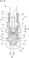
FIG. 1 is a side elevational view of a piston pump according to an embodiment of the present invention. -
FIG. 2 is a sectional view taken along a line II-II inFIG. 1 . -
FIG. 3 is a perspective sectional view taken along a line II-II inFIG. 1 . -
FIG. 4 is a perspective view of a ball biasing member of an outlet valve according to an embodiment of the present invention. -
FIG. 5 shows a state that a ball biasing member of an outlet valve according to an embodiment of the present invention is coupled to a cover. -
FIG. 6 shows an open state of the outlet valve according to an embodiment of the present invention. - Embodiments of the present invention will be described in detail with reference to the accompanying drawings hereinafter.
- A piston pump according to an embodiment of the present invention may be used as a part of a device for regulating a hydraulic pressure for an operation of a brake system of a vehicle, and may play a role of receiving a hydraulic oil discharged from a master cylinder of a vehicle and transmitting the received hydraulic oil to a wheel cylinder. The device for regulating the hydraulic oil pressure may include a plurality of solenoid valves, an accumulator, a motor or the like as well as a piston pump according to an embodiment of the present invention, and the piston pump, the solenoid valve, the accumulator, the motor or the like may be disposed within a modulator block.
- A piston pump according to an embodiment of the present invention may be disposed within a bore which is formed in a modulator block. At this time, an inlet port and an outlet port which are passages through which an oil is introduced into the bore and is discharged from the bore, and it may be configured that the oil introduced through the inlet port is discharged through the outlet port after having passed the piston pump according to an embodiment of the present invention.
- Referring to
FIG. 1 to FIG. 3 , asleeve housing 10 and apiston 20 are provided. - The
sleeve housing 10 includes abore 11. At this time, one side of thesleeve housing 10 is open and anoutlet hole 12 is provided at the other side thereof. - The
piston 20 is inserted into thebore 11 of thesleeve housing 10 so as to be able to reciprocally move. In detail, thepiston 20 is disposed to be reciprocally movable in a state that a distal end portion of thepiston 20 is inserted into thebore 11. As shown inFIG. 2 andFIG. 3 , a side of thesleeve housing 10 which is located opposite to a side where anoutlet hole 12 is formed is open, and the distal end portion of thepiston 20 is inserted into thebore 11 via an open space of thesleeve housing 10. At this time, not shown in the drawing, an end of thepiston 20 which is opposite to an end which is inserted into thebore 11 of thesleeve housing 10 may contact an eccentric spindle which is driven by a motor (not shown), and thus a reciprocal movement of thepiston 20 is resulted from the rotation of the eccentric spindle. Acoil spring 70 which elastically supports thepiston 20 with respect to thesleeve housing 10 is provided. Thepiston 20 is pushed by an eccentric spindle from a position shown inFIG. 2 andFIG. 3 toward theoutlet hole 12, and is returned to the position shown inFIG. 2 andFIG. 3 by thecoil spring 70. That is, thepiston 20 undergoes a reciprocal movement by the rotation of the eccentric spindle and thecoil spring 70. - At this time, as shown in
FIG. 2 andFIG. 3 , a sealingmember 22 for sealing between thepiston 20 and thesleeve housing 10 may be provided, and a sealingmember 23 for sealing between thepiston 20 and a portion where the eccentric spindle is disposed may be provided. As shown in the drawing, the sealing member indicated byreference numeral 22 may be elastically supported by thepiston 20 by thecoil spring 70 together with aretainer 53 of aninlet valve 50 which is described later. Meanwhile, the sealing member indicated by thereference numeral 23 may be supported by a separate supportingmember 25. The sealingmembers member 25 may have a shape of a ring. - An
inlet passage 21 for introducing an oil is provided in thepiston 20. As shown in the drawing, theinlet passage 21 may be comprised of aradial passage 21b which is elongated in a radially inward direction from an outer surface of thepiston 20 and a longitudinal passage which is elongated in a longitudinal direction of thepiston 20, and theradial passage 21b may be provided in a plural. Anoil filter 30 may be provided at an area where theradial passage 21b is formed. Theoil filter 30 may have a plurality of throughholes 31, and an oil in an inlet port (not shown) formed in the modulator block (not shown) may be introduced into theradial passage 21b after having passed theoil filter 30. - A space between the sleeve hosing 10 and the
piston 20 acts as acompression chamber 40. That is, a space between thesleeve housing 10 and thepiston 20 is thecompression chamber 40 in which an oil is compressed, and the oil is introduced into thecompression chamber 40 via theinlet passage 21 and is discharged from thecompression chamber 40 via theoutlet hole 12. - An
inlet valve 50 for regulating an introduction of an oil into thecompression chamber 40 and anoutlet valve 60 for regulating a discharge of an oil from thecompression chamber 40 are respectively provided. Theinlet valve 50 selectively opens/closes theinlet passage 21 so as to regulate the introduction of the oil, and theoutlet valve 60 selectively opens/closes theoutlet hole 12 so as to regulate the discharge of the oil. - The
inlet valve 50 may be formed by a ball-poppet valve. For example, as shown inFIG. 2 andFIG. 3 , the inlet valve may include aball 51 which opens or closes theinlet passage 21, acoil spring 52 elastically supporting theball 51, and aretainer 53 supporting thecoil spring 52. Theretainer 53 may include abody portion 53a which supports thecoil spring 52 and a plurality ofleg portions 53b which are respectively elongated from an outer end of thebody portion 53a. At this time, a supportingportion 53c which is elongated in a radially outward direction at an outer end of theleg portions 53b may be provided, and the supportingportion 53c is disposed to contact thepiston 20 and thecoil spring 70 supports the supportingportion 53c, and thereby theretainer 53 is elastically supported together with thepiston 20 by thecoil spring 70. - When the
ball 51 of theinlet valve 50 is positioned at a position shown inFIG. 2 andFIG. 3 , theinlet passage 21 is closed. Meanwhile, if thepiston 20 moves toward thedischarge hole 12 from the state ofFIG. 2 andFIG. 3 , thecoil spring 70 is compressed and theinlet valve 50 also moves toward thedischarge hole 12, and if the eccentric spindle further rotates from this state so that a force pushing thepiston 20 is removed, thepiston 20 returns to the position shown inFIG. 2 andFIG. 3 by a restoring force of thecoil spring 70, and during this process the return of theball 51 becomes later than the return of thepiston 20 so that theball 51 and thepiston 20 is temporarily separated from one another so as to open theinlet passage 21. While thepiston 20 moves toward thedischarge hole 12, the oil in thecompression chamber 40 is compressed to be discharged via thedischarge hole 12, and the oil is introduced into thecompression chamber 40 via theinlet passage 21 while theball 51 is maintained to be separated from thepiston 20. - Meanwhile, the
outlet valve 60 selectively opens/closes thedischarge hole 12 to regulate an oil discharge via thedischarge hole 12. - A
cover 80 for securing a space for theoutlet valve 60 is connected to thesleeve housing 10. Thecover 80 is, as shown inFIG. 2 andFIG. 3 , connected to thesleeve housing 10 to surround a portion where thedischarge hole 12 is formed. Thereby, a space is formed between thesleeve housing 10 and thecover 80, and theoutlet valve 60 is disposed between thesleeve housing 10 and thecover 80. - At this time, a
discharge chamber 90 in which the discharged oil is stored is formed between thesleeve housing 10 and thecover 80. The oil discharged through thedischarge hole 12 is discharged through an outlet port which is formed in a modulator block (not shown) via thedischarge chamber 90. - The
outlet valve 60 may be formed by a ball-poppet valve. For example, theoutlet valve 60 includes aball 61 and aball biasing member 62. - The
ball 61 is disposed between thesleeve housing 10 and thecover 80 to be reciprocally movable so as to selectively open/close thedischarge hole 12. Thedischarge hole 12 is closed if theball 61 closely contact thesleeve housing 10 as shown inFIG. 2 andFIG. 3 , and thedischarge hole 12 is opened if theball 61 is separated from thesleeve housing 10 as shown inFIG. 6 . - The
ball biasing member 62 exerts a force to urge theball 61 to move to a position of closing thedischarge hole 12. Meanwhile, theball biasing member 62 is configured such that anoil discharge passage 64 for discharging the oil discharged from thedischarge hole 12 to the outside is formed between thesleeve housing 10 and thecover 80. That is, theball biasing member 62 has a function of forming theoil discharge passage 64 as well as a function of providing an elastic force to urge theball 61 to move to the position of closing thedischarge hole 12. In a conventional piston pump an outlet valve of a piston pump has a coil spring for biasing a ball and a separate member for forming an oil discharge passage is provided or a groove for forming an oil discharge passage is formed in the sleeve housing, however in the present invention these two functions are realized by theball biasing member 62. Accordingly, theoutlet valve 60 according to an embodiment of the present invention has a reduced number of parts, a simple structure and an enhanced productability. - As shown in
FIG. 2 to FIG. 4 , theball biasing member 62 includes abody 621 which elastically supports theball 61 and a plurality oflegs 623 which are respectively connected to thebody 621. Referring toFIG. 4 , thebody 621 may be formed to have generally a shape of a circular plate, and thelegs 623 may be connected to an edge of thebody 621 and may be equidistantly disposed along a circumferential direction. Theleg 623 may, as shown inFIG. 4 , include a first longitudinally elongatedportion 623a, a radiallyelongated portion 623b and a second longitudinally elongatedportion 623c. At this time, the longitudinal direction means a direction parallel with the longitudinal direction of thepiston 20 and thesleeve housing 10. Although fourlegs 623 are shown in the drawing, the number of thelegs 623 is not limited thereto. - As shown in
FIG. 2 andFIG. 3 , thesleeve housing 10 and thecover 80 are disposed such that a gap is formed therebetween, and thelegs 623 are disposed to be inserted into the gap between thesleeve housing 10 and thecover 80. That is, as shown inFIG. 2 ,FIG. 3 andFIG. 5 , a gap betweeninner surfaces cover 80 and an outer surface of thesleeve housing 10 exists, the radiallyelongated portion 623b and the second longitudinally elongatedportion 623c are inserted into the gap between thesleeve housing 10 and thecover 80. In detail, the radiallyelongated portion 623b is disposed in a gap formed along a longitudinal direction of thesleeve housing 10 among the total gap between the sleeve hosing 10 and thecover 80, and the second longitudinally elongatedportion 623c is disposed in a gap formed along a radial direction of thesleeve housing 10 among the total gap between thesleeve housing 10 and thecover 80. The first longitudinally elongatedportion 623a is elongated along a longitudinal direction at an outer end of thebody 621 and connects thebody 621 and the radiallyelongated portion 623b together. Due to such a structure of thelegs 623 of theball biasing member 62, anoil discharge passage 64 is formed between thesleeve housing 10 and thecover 80. - If a pressure of an oil within the
compression chamber 40 acts on theball 61 during a compression process in a state that the radiallyelongated portion 623b and the second longitudinally elongatedportion 623c are fitted between thesleeve housing 10 and thecover 80 so as to be fixed, thebody 621 moves back by the pressure acting on theball 61 so as to be elastically deformed. Accordingly, as shown inFIG. 6 , if thepiston 20 is moves toward thedischarge hole 12 by the eccentric spindle, the pressure in thecompression chamber 40 increases, and theball 61 moves due to an increased pressure to a position where thedischarge hole 12 is opened. During this process, an oil which has been moved to thedischarge chamber 90 via thedischarge hole 12 is discharged to an outlet port (not shown) via theoil discharge passage 64. If the eccentric spindle further rotates from the state shown inFIG. 6 , theball 61 returns to the position shown inFIG. 2 , and the compression and the discharge of the oil are repeated by the rotation of the eccentric spindle. - The
body 621 may be formed to effectively support theball 61 by an elastic deformation. For example, thebody 621 may include anedge portion 621a and an elasticforce providing portion 621b. Theedge portion 621a may have a ring shape, and the elasticforce providing portion 621b may be formed to connect two different points of an inner circumferential surface of theedge portion 621a. At this time, the elasticforce providing portion 621b may be formed to have a curved shape so as to have a good elasticity. Thebody 621 may be formed of material having elastic deformation and restoration, and for example may be formed of metal having an elastic restoring force. - While this invention has been described in connection with what is presently considered to be practical exemplary embodiments, it is to be understood that the invention is not limited to the disclosed embodiments, but, on the contrary, is intended to cover various modifications and equivalent arrangements included within the spirit and scope of the appended claims.
- The present invention can be applied to a piston pump of a vehicle, so it has an industrial applicability.
Claims (12)
- An outlet valve which is formed between a sleeve housing and an outlet valve cover of a piston pump of a vehicle, comprising:a ball which is movably disposed between the sleeve housing and the outlet valve cover and selectively opens/closes a discharge hole which is formed in the sleeve housing depending on a movement thereof; anda ball biasing member which exerts a force to urge the ball to move a position where the discharge hole is closed,wherein the ball biasing member is formed such that an oil discharge passage for discharging an oil discharged via the discharge hole to an outside is formed between the sleeve housing and the outlet valve cover.
- The outlet valve of claim 1, wherein the ball biasing member comprises:a body which elastically supports the ball; anda plurality of legs which are respectively connected to the body.
- The outlet valve of claim 2, wherein the plurality of the legs are equidistantly disposed along a circumferential direction.
- The outlet valve of claim 2, wherein the sleeve housing and the outlet valve cover are disposed such that a gap exists therebetween.
- The outlet valve of claim 4, wherein the respective leg comprises:a radially elongated portion which is disposed in a gap formed in a longitudinal direction of the sleeve housing among the gap between the sleeve housing and the outlet valve cover; anda longitudinally elongated portion which is disposed in a gap formed in a radial direction of the sleeve housing among the gap between the sleeve housing and the outlet valve cover.
- The outlet valve of claim 2, wherein the body comprises:an edge portion having a ring shape; andan elastic force providing portion which connects two different points of an inner circumferential surface of the edge portion.
- A piston pump comprising:a sleeve housing which forms a bore and is provided with a discharge hole;a piston which has an inlet passage through which an oil is introduced into the bore and is inserted into the bore to be reciprocally movable;an inlet valve which is configured to open/close the inlet passage;a cover which is connected to the sleeve housing to surround a portion where the discharge hole is formed; andan outlet valve which is configured to open/close the discharge hole,wherein the outlet valve comprises:a ball which is movably disposed between the sleeve housing and the cover to open/close selectively the discharge hole; anda ball biasing member which exerts a force to urge the ball to move a position where the discharge hole is closed,and wherein the ball biasing member is formed such that an oil discharge passage for discharging an oil discharged via the discharge hole to an outside is formed between the sleeve housing and the cover.
- The piston pump of claim 7, wherein the ball biasing member comprises:a body which elastically supports the ball; anda plurality of legs which are respectively connected to the body.
- The piston pump of claim 8, wherein the plurality of the legs are equidistantly disposed along a circumferential direction.
- The piston pump of claim 8, wherein the sleeve housing and the outlet valve cover are disposed such that a gap exists therebetween.
- The piston pump of claim 10, wherein the respective leg comprises:a radially elongated portion which is disposed in a gap formed in a longitudinal direction of the sleeve housing among the gap between the sleeve housing and the cover; anda longitudinally elongated portion which is disposed in a gap formed in a radial direction of the sleeve housing among the gap between the sleeve housing and the cover.
- The piston pump of claim 8, wherein the body comprises:an edge portion having a ring shape; andan elastic force providing portion which connects two different points of an inner circumferential surface of the edge portion.
Applications Claiming Priority (2)
| Application Number | Priority Date | Filing Date | Title |
|---|---|---|---|
| KR1020160094278A KR101915501B1 (en) | 2016-07-25 | 2016-07-25 | Piston pump for brake system of vehicles |
| PCT/KR2017/007809 WO2018021758A1 (en) | 2016-07-25 | 2017-07-20 | Piston pump for vehicle brake system |
Publications (3)
| Publication Number | Publication Date |
|---|---|
| EP3473508A1 true EP3473508A1 (en) | 2019-04-24 |
| EP3473508A4 EP3473508A4 (en) | 2020-01-22 |
| EP3473508B1 EP3473508B1 (en) | 2022-06-15 |
Family
ID=61017277
Family Applications (1)
| Application Number | Title | Priority Date | Filing Date |
|---|---|---|---|
| EP17834700.1A Active EP3473508B1 (en) | 2016-07-25 | 2017-07-20 | Piston pump for vehicle brake system |
Country Status (4)
| Country | Link |
|---|---|
| EP (1) | EP3473508B1 (en) |
| KR (1) | KR101915501B1 (en) |
| CN (1) | CN109476293B (en) |
| WO (1) | WO2018021758A1 (en) |
Families Citing this family (5)
| Publication number | Priority date | Publication date | Assignee | Title |
|---|---|---|---|---|
| KR102416288B1 (en) * | 2018-02-08 | 2022-07-05 | 현대모비스 주식회사 | Pump device for electronic control brake system |
| US11339688B2 (en) | 2020-01-29 | 2022-05-24 | Borgwarner, Inc. | Variable camshaft timing valve assembly |
| US11506110B2 (en) * | 2020-05-18 | 2022-11-22 | Schaeffler Technologies AG & Co. KG | Oil-spray tube with poppet valve |
| CN112483661B (en) * | 2020-12-17 | 2022-09-06 | 东方电气集团东方电机有限公司 | Exhaust structure suitable for generator lubricating oil circulation pipeline system |
| CN114857023B (en) * | 2022-04-26 | 2023-09-08 | 安徽理工大学 | Pressurized anti-countercurrent water pump |
Family Cites Families (14)
| Publication number | Priority date | Publication date | Assignee | Title |
|---|---|---|---|---|
| EP1055072B1 (en) * | 1998-02-09 | 2002-09-04 | Continental Teves AG & Co. oHG | Pressure valve, especially for a piston pump |
| DE10013858A1 (en) * | 2000-03-21 | 2001-09-27 | Continental Teves Ag & Co Ohg | Piston pump with valve assembly unit has one end of spring on valve seat carrier and other attached to piston |
| DE102006029368A1 (en) * | 2006-06-27 | 2008-01-03 | Robert Bosch Gmbh | Piston pump for a vehicle brake system with a sealing element |
| KR100827272B1 (en) * | 2007-04-09 | 2008-05-07 | 주식회사 만도 | Pump for electronically controlled brake system |
| CN201090391Y (en) * | 2007-07-19 | 2008-07-23 | 万安集团上海汽车控制系统有限公司 | Automobile hydraulic pressure anti-lock braking system plunger pump |
| DE102009054520A1 (en) * | 2009-12-10 | 2011-06-16 | Robert Bosch Gmbh | piston pump |
| DE102009055228A1 (en) * | 2009-12-23 | 2011-06-30 | Robert Bosch GmbH, 70469 | Piston pump for a hydraulic vehicle brake system |
| DE102011075518A1 (en) * | 2010-09-02 | 2012-04-26 | Robert Bosch Gmbh | Arrangement for throttling a fluid flow and corresponding piston pump for conveying fluids |
| DE102010040329A1 (en) * | 2010-09-07 | 2012-03-08 | Robert Bosch Gmbh | Pump element of piston pump used in vehicle brake system, has valve structure that is pushed on the valve seat by biasing structure that is supported by the valve housing |
| DE102010062174A1 (en) * | 2010-11-30 | 2012-05-31 | Robert Bosch Gmbh | Valve, in particular an outlet valve of a hydraulic piston pump |
| DE102011002982B4 (en) * | 2011-01-21 | 2022-05-25 | Robert Bosch Gmbh | Spring element and corresponding piston pump for pumping fluids |
| JP5949455B2 (en) * | 2012-10-31 | 2016-07-06 | アイシン・エィ・ダブリュ株式会社 | Electromagnetic pump |
| KR102196190B1 (en) * | 2014-04-10 | 2020-12-30 | 주식회사 만도 | Piston pump assembly of electric controlled brake device for vehicle |
| JP2016121666A (en) * | 2014-12-25 | 2016-07-07 | 株式会社アドヴィックス | Piston pump for brake device |
-
2016
- 2016-07-25 KR KR1020160094278A patent/KR101915501B1/en active Active
-
2017
- 2017-07-20 EP EP17834700.1A patent/EP3473508B1/en active Active
- 2017-07-20 WO PCT/KR2017/007809 patent/WO2018021758A1/en not_active Ceased
- 2017-07-20 CN CN201780045770.XA patent/CN109476293B/en active Active
Also Published As
| Publication number | Publication date |
|---|---|
| EP3473508A4 (en) | 2020-01-22 |
| CN109476293A (en) | 2019-03-15 |
| KR101915501B1 (en) | 2018-11-08 |
| CN109476293B (en) | 2021-05-11 |
| EP3473508B1 (en) | 2022-06-15 |
| WO2018021758A1 (en) | 2018-02-01 |
| KR20180011644A (en) | 2018-02-02 |
Similar Documents
| Publication | Publication Date | Title |
|---|---|---|
| EP3473508B1 (en) | Piston pump for vehicle brake system | |
| US11421678B2 (en) | Piston pump for brake system of vehicle | |
| US7993115B2 (en) | Pump of electronically controlled brake system | |
| CN101849106B (en) | Plastic component, piston pump and assembly method | |
| US9346447B2 (en) | Solenoid valve for brake system | |
| JP4490277B2 (en) | Supply device | |
| JPH04303182A (en) | Hydraulic type reciprocating piston pump for automobile brake gear with antiskid device | |
| CN109844310B (en) | Pump device and brake device | |
| KR102196931B1 (en) | Piston pump for brake system of vehicles | |
| KR101992207B1 (en) | Piston pump for brake system of vehicles | |
| KR20170130940A (en) | Manufacturing method of piston and pump for brake system including piston | |
| JP2008506891A (en) | Piston pump with improved pressure boosting dynamics | |
| KR102085063B1 (en) | Piston pump for brake system of vehicles | |
| KR20070054349A (en) | Pump of brake system | |
| KR100550947B1 (en) | Pumps for brake systems | |
| KR102079640B1 (en) | Piston pump for brake system of vehicles | |
| KR100882791B1 (en) | Pump for electronically controlled brake system | |
| EP1869319B1 (en) | Piston pump for a vehicle brake system | |
| JP2001001885A5 (en) | ||
| KR102314011B1 (en) | Piston pump for brake system of vehicles | |
| KR102318068B1 (en) | Pump unit for electronic control brake system | |
| WO2006057371A1 (en) | Hydraulic fluid reservoir and hydraulic pressure control unit | |
| KR20180025590A (en) | Piston pump for brake system of vehicles | |
| KR20030075649A (en) | A bearing stopper of electronic control brake system | |
| JPH08254186A (en) | Plunger pump |
Legal Events
| Date | Code | Title | Description |
|---|---|---|---|
| STAA | Information on the status of an ep patent application or granted ep patent |
Free format text: STATUS: THE INTERNATIONAL PUBLICATION HAS BEEN MADE |
|
| PUAI | Public reference made under article 153(3) epc to a published international application that has entered the european phase |
Free format text: ORIGINAL CODE: 0009012 |
|
| STAA | Information on the status of an ep patent application or granted ep patent |
Free format text: STATUS: REQUEST FOR EXAMINATION WAS MADE |
|
| 17P | Request for examination filed |
Effective date: 20190115 |
|
| AK | Designated contracting states |
Kind code of ref document: A1 Designated state(s): AL AT BE BG CH CY CZ DE DK EE ES FI FR GB GR HR HU IE IS IT LI LT LU LV MC MK MT NL NO PL PT RO RS SE SI SK SM TR |
|
| AX | Request for extension of the european patent |
Extension state: BA ME |
|
| DAV | Request for validation of the european patent (deleted) | ||
| DAX | Request for extension of the european patent (deleted) | ||
| A4 | Supplementary search report drawn up and despatched |
Effective date: 20191219 |
|
| RIC1 | Information provided on ipc code assigned before grant |
Ipc: F16K 15/04 20060101ALI20191213BHEP Ipc: B60T 15/02 20060101ALI20191213BHEP Ipc: F16K 27/02 20060101ALI20191213BHEP Ipc: B60T 8/40 20060101AFI20191213BHEP Ipc: F04B 53/10 20060101ALI20191213BHEP |
|
| GRAP | Despatch of communication of intention to grant a patent |
Free format text: ORIGINAL CODE: EPIDOSNIGR1 |
|
| STAA | Information on the status of an ep patent application or granted ep patent |
Free format text: STATUS: GRANT OF PATENT IS INTENDED |
|
| INTG | Intention to grant announced |
Effective date: 20220321 |
|
| GRAS | Grant fee paid |
Free format text: ORIGINAL CODE: EPIDOSNIGR3 |
|
| GRAA | (expected) grant |
Free format text: ORIGINAL CODE: 0009210 |
|
| STAA | Information on the status of an ep patent application or granted ep patent |
Free format text: STATUS: THE PATENT HAS BEEN GRANTED |
|
| AK | Designated contracting states |
Kind code of ref document: B1 Designated state(s): AL AT BE BG CH CY CZ DE DK EE ES FI FR GB GR HR HU IE IS IT LI LT LU LV MC MK MT NL NO PL PT RO RS SE SI SK SM TR |
|
| REG | Reference to a national code |
Ref country code: CH Ref legal event code: EP Ref country code: GB Ref legal event code: FG4D |
|
| REG | Reference to a national code |
Ref country code: IE Ref legal event code: FG4D |
|
| REG | Reference to a national code |
Ref country code: DE Ref legal event code: R096 Ref document number: 602017058599 Country of ref document: DE |
|
| REG | Reference to a national code |
Ref country code: AT Ref legal event code: REF Ref document number: 1498211 Country of ref document: AT Kind code of ref document: T Effective date: 20220715 |
|
| REG | Reference to a national code |
Ref country code: LT Ref legal event code: MG9D |
|
| REG | Reference to a national code |
Ref country code: NL Ref legal event code: MP Effective date: 20220615 |
|
| PG25 | Lapsed in a contracting state [announced via postgrant information from national office to epo] |
Ref country code: SE Free format text: LAPSE BECAUSE OF FAILURE TO SUBMIT A TRANSLATION OF THE DESCRIPTION OR TO PAY THE FEE WITHIN THE PRESCRIBED TIME-LIMIT Effective date: 20220615 Ref country code: NO Free format text: LAPSE BECAUSE OF FAILURE TO SUBMIT A TRANSLATION OF THE DESCRIPTION OR TO PAY THE FEE WITHIN THE PRESCRIBED TIME-LIMIT Effective date: 20220915 Ref country code: LT Free format text: LAPSE BECAUSE OF FAILURE TO SUBMIT A TRANSLATION OF THE DESCRIPTION OR TO PAY THE FEE WITHIN THE PRESCRIBED TIME-LIMIT Effective date: 20220615 Ref country code: HR Free format text: LAPSE BECAUSE OF FAILURE TO SUBMIT A TRANSLATION OF THE DESCRIPTION OR TO PAY THE FEE WITHIN THE PRESCRIBED TIME-LIMIT Effective date: 20220615 Ref country code: GR Free format text: LAPSE BECAUSE OF FAILURE TO SUBMIT A TRANSLATION OF THE DESCRIPTION OR TO PAY THE FEE WITHIN THE PRESCRIBED TIME-LIMIT Effective date: 20220916 Ref country code: FI Free format text: LAPSE BECAUSE OF FAILURE TO SUBMIT A TRANSLATION OF THE DESCRIPTION OR TO PAY THE FEE WITHIN THE PRESCRIBED TIME-LIMIT Effective date: 20220615 Ref country code: BG Free format text: LAPSE BECAUSE OF FAILURE TO SUBMIT A TRANSLATION OF THE DESCRIPTION OR TO PAY THE FEE WITHIN THE PRESCRIBED TIME-LIMIT Effective date: 20220915 |
|
| REG | Reference to a national code |
Ref country code: AT Ref legal event code: MK05 Ref document number: 1498211 Country of ref document: AT Kind code of ref document: T Effective date: 20220615 |
|
| PG25 | Lapsed in a contracting state [announced via postgrant information from national office to epo] |
Ref country code: RS Free format text: LAPSE BECAUSE OF FAILURE TO SUBMIT A TRANSLATION OF THE DESCRIPTION OR TO PAY THE FEE WITHIN THE PRESCRIBED TIME-LIMIT Effective date: 20220615 Ref country code: LV Free format text: LAPSE BECAUSE OF FAILURE TO SUBMIT A TRANSLATION OF THE DESCRIPTION OR TO PAY THE FEE WITHIN THE PRESCRIBED TIME-LIMIT Effective date: 20220615 |
|
| PG25 | Lapsed in a contracting state [announced via postgrant information from national office to epo] |
Ref country code: NL Free format text: LAPSE BECAUSE OF FAILURE TO SUBMIT A TRANSLATION OF THE DESCRIPTION OR TO PAY THE FEE WITHIN THE PRESCRIBED TIME-LIMIT Effective date: 20220615 |
|
| PG25 | Lapsed in a contracting state [announced via postgrant information from national office to epo] |
Ref country code: SM Free format text: LAPSE BECAUSE OF FAILURE TO SUBMIT A TRANSLATION OF THE DESCRIPTION OR TO PAY THE FEE WITHIN THE PRESCRIBED TIME-LIMIT Effective date: 20220615 Ref country code: SK Free format text: LAPSE BECAUSE OF FAILURE TO SUBMIT A TRANSLATION OF THE DESCRIPTION OR TO PAY THE FEE WITHIN THE PRESCRIBED TIME-LIMIT Effective date: 20220615 Ref country code: RO Free format text: LAPSE BECAUSE OF FAILURE TO SUBMIT A TRANSLATION OF THE DESCRIPTION OR TO PAY THE FEE WITHIN THE PRESCRIBED TIME-LIMIT Effective date: 20220615 Ref country code: PT Free format text: LAPSE BECAUSE OF FAILURE TO SUBMIT A TRANSLATION OF THE DESCRIPTION OR TO PAY THE FEE WITHIN THE PRESCRIBED TIME-LIMIT Effective date: 20221017 Ref country code: ES Free format text: LAPSE BECAUSE OF FAILURE TO SUBMIT A TRANSLATION OF THE DESCRIPTION OR TO PAY THE FEE WITHIN THE PRESCRIBED TIME-LIMIT Effective date: 20220615 Ref country code: EE Free format text: LAPSE BECAUSE OF FAILURE TO SUBMIT A TRANSLATION OF THE DESCRIPTION OR TO PAY THE FEE WITHIN THE PRESCRIBED TIME-LIMIT Effective date: 20220615 Ref country code: CZ Free format text: LAPSE BECAUSE OF FAILURE TO SUBMIT A TRANSLATION OF THE DESCRIPTION OR TO PAY THE FEE WITHIN THE PRESCRIBED TIME-LIMIT Effective date: 20220615 Ref country code: AT Free format text: LAPSE BECAUSE OF FAILURE TO SUBMIT A TRANSLATION OF THE DESCRIPTION OR TO PAY THE FEE WITHIN THE PRESCRIBED TIME-LIMIT Effective date: 20220615 |
|
| PG25 | Lapsed in a contracting state [announced via postgrant information from national office to epo] |
Ref country code: PL Free format text: LAPSE BECAUSE OF FAILURE TO SUBMIT A TRANSLATION OF THE DESCRIPTION OR TO PAY THE FEE WITHIN THE PRESCRIBED TIME-LIMIT Effective date: 20220615 Ref country code: IS Free format text: LAPSE BECAUSE OF FAILURE TO SUBMIT A TRANSLATION OF THE DESCRIPTION OR TO PAY THE FEE WITHIN THE PRESCRIBED TIME-LIMIT Effective date: 20221015 |
|
| REG | Reference to a national code |
Ref country code: CH Ref legal event code: PL |
|
| REG | Reference to a national code |
Ref country code: DE Ref legal event code: R097 Ref document number: 602017058599 Country of ref document: DE |
|
| REG | Reference to a national code |
Ref country code: BE Ref legal event code: MM Effective date: 20220731 |
|
| PG25 | Lapsed in a contracting state [announced via postgrant information from national office to epo] |
Ref country code: MC Free format text: LAPSE BECAUSE OF FAILURE TO SUBMIT A TRANSLATION OF THE DESCRIPTION OR TO PAY THE FEE WITHIN THE PRESCRIBED TIME-LIMIT Effective date: 20220615 Ref country code: AL Free format text: LAPSE BECAUSE OF FAILURE TO SUBMIT A TRANSLATION OF THE DESCRIPTION OR TO PAY THE FEE WITHIN THE PRESCRIBED TIME-LIMIT Effective date: 20220615 |
|
| PLBE | No opposition filed within time limit |
Free format text: ORIGINAL CODE: 0009261 |
|
| STAA | Information on the status of an ep patent application or granted ep patent |
Free format text: STATUS: NO OPPOSITION FILED WITHIN TIME LIMIT |
|
| PG25 | Lapsed in a contracting state [announced via postgrant information from national office to epo] |
Ref country code: LU Free format text: LAPSE BECAUSE OF NON-PAYMENT OF DUE FEES Effective date: 20220720 Ref country code: LI Free format text: LAPSE BECAUSE OF NON-PAYMENT OF DUE FEES Effective date: 20220731 Ref country code: DK Free format text: LAPSE BECAUSE OF FAILURE TO SUBMIT A TRANSLATION OF THE DESCRIPTION OR TO PAY THE FEE WITHIN THE PRESCRIBED TIME-LIMIT Effective date: 20220615 Ref country code: CH Free format text: LAPSE BECAUSE OF NON-PAYMENT OF DUE FEES Effective date: 20220731 |
|
| 26N | No opposition filed |
Effective date: 20230316 |
|
| PG25 | Lapsed in a contracting state [announced via postgrant information from national office to epo] |
Ref country code: SI Free format text: LAPSE BECAUSE OF FAILURE TO SUBMIT A TRANSLATION OF THE DESCRIPTION OR TO PAY THE FEE WITHIN THE PRESCRIBED TIME-LIMIT Effective date: 20220615 Ref country code: BE Free format text: LAPSE BECAUSE OF NON-PAYMENT OF DUE FEES Effective date: 20220731 |
|
| PG25 | Lapsed in a contracting state [announced via postgrant information from national office to epo] |
Ref country code: IE Free format text: LAPSE BECAUSE OF NON-PAYMENT OF DUE FEES Effective date: 20220720 Ref country code: FR Free format text: LAPSE BECAUSE OF NON-PAYMENT OF DUE FEES Effective date: 20220815 |
|
| PG25 | Lapsed in a contracting state [announced via postgrant information from national office to epo] |
Ref country code: IT Free format text: LAPSE BECAUSE OF FAILURE TO SUBMIT A TRANSLATION OF THE DESCRIPTION OR TO PAY THE FEE WITHIN THE PRESCRIBED TIME-LIMIT Effective date: 20220615 |
|
| PG25 | Lapsed in a contracting state [announced via postgrant information from national office to epo] |
Ref country code: HU Free format text: LAPSE BECAUSE OF FAILURE TO SUBMIT A TRANSLATION OF THE DESCRIPTION OR TO PAY THE FEE WITHIN THE PRESCRIBED TIME-LIMIT; INVALID AB INITIO Effective date: 20170720 |
|
| PG25 | Lapsed in a contracting state [announced via postgrant information from national office to epo] |
Ref country code: MK Free format text: LAPSE BECAUSE OF FAILURE TO SUBMIT A TRANSLATION OF THE DESCRIPTION OR TO PAY THE FEE WITHIN THE PRESCRIBED TIME-LIMIT Effective date: 20220615 Ref country code: CY Free format text: LAPSE BECAUSE OF FAILURE TO SUBMIT A TRANSLATION OF THE DESCRIPTION OR TO PAY THE FEE WITHIN THE PRESCRIBED TIME-LIMIT Effective date: 20220615 |
|
| PG25 | Lapsed in a contracting state [announced via postgrant information from national office to epo] |
Ref country code: TR Free format text: LAPSE BECAUSE OF FAILURE TO SUBMIT A TRANSLATION OF THE DESCRIPTION OR TO PAY THE FEE WITHIN THE PRESCRIBED TIME-LIMIT Effective date: 20220615 |
|
| PG25 | Lapsed in a contracting state [announced via postgrant information from national office to epo] |
Ref country code: MT Free format text: LAPSE BECAUSE OF FAILURE TO SUBMIT A TRANSLATION OF THE DESCRIPTION OR TO PAY THE FEE WITHIN THE PRESCRIBED TIME-LIMIT Effective date: 20220615 |
|
| PG25 | Lapsed in a contracting state [announced via postgrant information from national office to epo] |
Ref country code: BG Free format text: LAPSE BECAUSE OF FAILURE TO SUBMIT A TRANSLATION OF THE DESCRIPTION OR TO PAY THE FEE WITHIN THE PRESCRIBED TIME-LIMIT Effective date: 20220615 |
|
| PG25 | Lapsed in a contracting state [announced via postgrant information from national office to epo] |
Ref country code: BG Free format text: LAPSE BECAUSE OF FAILURE TO SUBMIT A TRANSLATION OF THE DESCRIPTION OR TO PAY THE FEE WITHIN THE PRESCRIBED TIME-LIMIT Effective date: 20220615 |
|
| PGFP | Annual fee paid to national office [announced via postgrant information from national office to epo] |
Ref country code: GB Payment date: 20250619 Year of fee payment: 9 |
|
| REG | Reference to a national code |
Ref country code: DE Ref legal event code: R081 Ref document number: 602017058599 Country of ref document: DE Owner name: HANSAE MOBILITY CO., LTD., DAEGU, KR Free format text: FORMER OWNER: ERAE AMS CO., LTD., DAEGU, KR |
|
| PGFP | Annual fee paid to national office [announced via postgrant information from national office to epo] |
Ref country code: DE Payment date: 20250618 Year of fee payment: 9 |