EP3473149B1 - Levitation fluid dispenser - Google Patents
Levitation fluid dispenser Download PDFInfo
- Publication number
- EP3473149B1 EP3473149B1 EP18207549.9A EP18207549A EP3473149B1 EP 3473149 B1 EP3473149 B1 EP 3473149B1 EP 18207549 A EP18207549 A EP 18207549A EP 3473149 B1 EP3473149 B1 EP 3473149B1
- Authority
- EP
- European Patent Office
- Prior art keywords
- drop
- air
- hand
- fluid
- user
- Prior art date
- Legal status (The legal status is an assumption and is not a legal conclusion. Google has not performed a legal analysis and makes no representation as to the accuracy of the status listed.)
- Active
Links
- 239000012530 fluid Substances 0.000 title claims description 101
- 238000005339 levitation Methods 0.000 title description 21
- 238000011144 upstream manufacturing Methods 0.000 claims description 60
- 238000004140 cleaning Methods 0.000 claims description 30
- 230000007246 mechanism Effects 0.000 claims description 28
- XLYOFNOQVPJJNP-UHFFFAOYSA-N water Substances O XLYOFNOQVPJJNP-UHFFFAOYSA-N 0.000 claims description 22
- 230000007423 decrease Effects 0.000 claims description 4
- 239000003814 drug Substances 0.000 claims description 3
- 229940079593 drug Drugs 0.000 claims description 3
- 238000001035 drying Methods 0.000 claims description 3
- 238000004891 communication Methods 0.000 claims description 2
- 239000000077 insect repellent Substances 0.000 claims description 2
- 239000002304 perfume Substances 0.000 claims description 2
- 239000004909 Moisturizer Substances 0.000 claims 1
- 230000001186 cumulative effect Effects 0.000 claims 1
- 239000000645 desinfectant Substances 0.000 claims 1
- 230000001333 moisturizer Effects 0.000 claims 1
- 239000007788 liquid Substances 0.000 description 13
- 238000012544 monitoring process Methods 0.000 description 9
- LFQSCWFLJHTTHZ-UHFFFAOYSA-N Ethanol Chemical compound CCO LFQSCWFLJHTTHZ-UHFFFAOYSA-N 0.000 description 8
- 238000010276 construction Methods 0.000 description 7
- 239000000344 soap Substances 0.000 description 7
- 239000000499 gel Substances 0.000 description 6
- 238000000034 method Methods 0.000 description 5
- 238000007605 air drying Methods 0.000 description 4
- 230000000694 effects Effects 0.000 description 4
- 239000000463 material Substances 0.000 description 4
- 239000000758 substrate Substances 0.000 description 4
- 238000013459 approach Methods 0.000 description 2
- 238000002483 medication Methods 0.000 description 2
- 239000000203 mixture Substances 0.000 description 2
- 230000003020 moisturizing effect Effects 0.000 description 2
- 238000011012 sanitization Methods 0.000 description 2
- -1 tissue Substances 0.000 description 2
- 238000005406 washing Methods 0.000 description 2
- 208000035473 Communicable disease Diseases 0.000 description 1
- 241000238631 Hexapoda Species 0.000 description 1
- CBENFWSGALASAD-UHFFFAOYSA-N Ozone Chemical compound [O-][O+]=O CBENFWSGALASAD-UHFFFAOYSA-N 0.000 description 1
- 208000003251 Pruritus Diseases 0.000 description 1
- 230000004913 activation Effects 0.000 description 1
- 239000003570 air Substances 0.000 description 1
- 230000000844 anti-bacterial effect Effects 0.000 description 1
- 210000000436 anus Anatomy 0.000 description 1
- 239000003899 bactericide agent Substances 0.000 description 1
- 239000002775 capsule Substances 0.000 description 1
- 239000000306 component Substances 0.000 description 1
- 239000002131 composite material Substances 0.000 description 1
- 238000011109 contamination Methods 0.000 description 1
- 239000006071 cream Substances 0.000 description 1
- 238000012864 cross contamination Methods 0.000 description 1
- 230000003247 decreasing effect Effects 0.000 description 1
- 239000002781 deodorant agent Substances 0.000 description 1
- 230000001419 dependent effect Effects 0.000 description 1
- 230000002951 depilatory effect Effects 0.000 description 1
- 230000000249 desinfective effect Effects 0.000 description 1
- 238000007599 discharging Methods 0.000 description 1
- 238000001704 evaporation Methods 0.000 description 1
- 230000008020 evaporation Effects 0.000 description 1
- 239000004744 fabric Substances 0.000 description 1
- 238000007667 floating Methods 0.000 description 1
- 239000006260 foam Substances 0.000 description 1
- 239000000417 fungicide Substances 0.000 description 1
- 239000011521 glass Substances 0.000 description 1
- 230000035876 healing Effects 0.000 description 1
- 208000015181 infectious disease Diseases 0.000 description 1
- 239000006210 lotion Substances 0.000 description 1
- 239000000314 lubricant Substances 0.000 description 1
- 238000002156 mixing Methods 0.000 description 1
- 238000012986 modification Methods 0.000 description 1
- 230000004048 modification Effects 0.000 description 1
- 239000002245 particle Substances 0.000 description 1
- 230000009467 reduction Effects 0.000 description 1
- 230000001846 repelling effect Effects 0.000 description 1
- 239000002453 shampoo Substances 0.000 description 1
- 239000000126 substance Substances 0.000 description 1
- 230000001960 triggered effect Effects 0.000 description 1
- 230000000007 visual effect Effects 0.000 description 1
- 239000002699 waste material Substances 0.000 description 1
Images


Classifications
-
- A—HUMAN NECESSITIES
- A47—FURNITURE; DOMESTIC ARTICLES OR APPLIANCES; COFFEE MILLS; SPICE MILLS; SUCTION CLEANERS IN GENERAL
- A47K—SANITARY EQUIPMENT NOT OTHERWISE PROVIDED FOR; TOILET ACCESSORIES
- A47K5/00—Holders or dispensers for soap, toothpaste, or the like
- A47K5/06—Dispensers for soap
- A47K5/12—Dispensers for soap for liquid or pasty soap
- A47K5/1217—Electrical control means for the dispensing mechanism
-
- A—HUMAN NECESSITIES
- A47—FURNITURE; DOMESTIC ARTICLES OR APPLIANCES; COFFEE MILLS; SPICE MILLS; SUCTION CLEANERS IN GENERAL
- A47K—SANITARY EQUIPMENT NOT OTHERWISE PROVIDED FOR; TOILET ACCESSORIES
- A47K5/00—Holders or dispensers for soap, toothpaste, or the like
- A47K5/06—Dispensers for soap
- A47K5/12—Dispensers for soap for liquid or pasty soap
- A47K5/1202—Dispensers for soap for liquid or pasty soap dispensing dosed volume
-
- E—FIXED CONSTRUCTIONS
- E03—WATER SUPPLY; SEWERAGE
- E03C—DOMESTIC PLUMBING INSTALLATIONS FOR FRESH WATER OR WASTE WATER; SINKS
- E03C1/00—Domestic plumbing installations for fresh water or waste water; Sinks
- E03C1/02—Plumbing installations for fresh water
- E03C1/04—Water-basin installations specially adapted to wash-basins or baths
- E03C1/0404—Constructional or functional features of the spout
-
- A—HUMAN NECESSITIES
- A47—FURNITURE; DOMESTIC ARTICLES OR APPLIANCES; COFFEE MILLS; SPICE MILLS; SUCTION CLEANERS IN GENERAL
- A47K—SANITARY EQUIPMENT NOT OTHERWISE PROVIDED FOR; TOILET ACCESSORIES
- A47K5/00—Holders or dispensers for soap, toothpaste, or the like
- A47K5/06—Dispensers for soap
- A47K5/12—Dispensers for soap for liquid or pasty soap
- A47K2005/1218—Table mounted; Dispensers integrated with the mixing tap
-
- A—HUMAN NECESSITIES
- A47—FURNITURE; DOMESTIC ARTICLES OR APPLIANCES; COFFEE MILLS; SPICE MILLS; SUCTION CLEANERS IN GENERAL
- A47K—SANITARY EQUIPMENT NOT OTHERWISE PROVIDED FOR; TOILET ACCESSORIES
- A47K5/00—Holders or dispensers for soap, toothpaste, or the like
- A47K5/06—Dispensers for soap
- A47K5/12—Dispensers for soap for liquid or pasty soap
- A47K5/1211—Dispensers for soap for liquid or pasty soap using pressure on soap, e.g. with piston
Description
- This invention relates to devices that dispense fluids, notably hand fluids to be used on a person's hands such as hand soap or hand sanitizer. More particularly, the invention provides a fluid dispenser having a levitation device for suspending a drop of hand fluid in midair, and a method of dispensing a fluid by levitating a drop of the fluid for grasping by a hand of a user.
- The importance of regular hand cleaning in reducing the spread of infectious disease is well known. Nonetheless, many individuals fail to wash their hands regularly. These individuals may, for example, forget to wash their hands, fail to notice hand cleaning stations, or consider hand washing to be a tedious and unstimulating activity.
- The present inventors have appreciated that the experience of the application of fluids including hand cleaning onto a user's hand could be improved by providing a visually interesting display of the fluid, thereby attracting attention and encouraging more frequent application of fluids to a user's hand and hand cleaning.
- Prior art with respect to levitation fluid dispensers is disclosed in
US 5 215 688 A ,EP 0 018 137 A1CN 201 629 075 UUS 5 215 688 A discloses the features of the preamble of claim 1. - To at least partially overcome some of the disadvantages of previously known devices, the invention provides a fluid dispenser that incorporates a levitation device. The levitation device is operable to levitate a drop of fluid at a position where the drop is readily visible and accessible to be taken by a user's hand.
- The present inventors have appreciated that a levitating drop of a fluid, visibly floating in midair, can attract the attention and interest of nearby individuals, and encourage them to grasp the fluid with their hands. The dispenser incorporates a proximity sensor which triggers the discharge and levitation of a drop of fluid upon detecting a nearby individual. A display of lights and/or sounds could also be used to draw attention to the levitating drop, and encourage the individual to approach the display and grasp the drop with his or her hands before leaving the area. The levitating drop could be lit up, rotated, moved up and down, and/or moved along a path, such as a circle or
figure 8 , to further draw attention thereto. - The levitating drop is levitated such that it may be grasped by a person's hand, preferably with the user's hand swiping the drop, by moving the user's hand to engage the levitating drop. Preferably, the user's hand is moved into engagement with the drop that the drop is engaged by the hand while still levitated. Preferably, the hand is moved sideways to grasp the drop.
- The fluid of the drop may be grasped directly by the hand of a person to engage the skin of the hand or may be grasped with the user holding a substrate such as a cloth, tissue, paper towel or other substrate or object in the user's and which the drop is to engage.
- The fluid may preferably be a "hand fluid" to be used on the user's hands. The fluid may be a "user fluid" to be used on a person, for example, by grasping by the user's hand and applied to other portions of a user's body such as onto a person's external skin such as to their face, feet, arms, legs, torso, anus and onto their hair.
- As used in this application, the term "hand fluid" means a fluid that is to be used on the hands of a person including without limitation fluids for cleaning, disinfecting, sanitizing, moisturizing, medicating, insect repelling, scenting and perfuming. More specific examples of such hand fluids include hand soap, alcohol based sanitizing and cleaning compositions, skin moisturizing fluids and lotions, fluids containing medications such as anti-itching components, skin healing components, fungicides, bactericides and the like, insect repellent fluids, and perfumes.
- User fluids include the above fluids which are "hand fluids" and include fluids for other uses such as hemorrhoidal medications, foot deodorant liquids, hair conditioner liquids, hair shampoos, shaving liquids, depilatory liquids, lubricants, teeth cleaning liquid and the like.
- Insofar as the drop is engaged by a substrate, like a paper tissue held in the user's hand, then the fluid may be almost any manner of fluid that is desired to be applied to an object via the substrate, preferably to a person's body but to other objects such as to surfaces to be treated or cleaned like reading glasses, tabletops and the like.
- The subject matter of the present invention is defined by the feature of claim 1. Preferred embodiments are the subject of the dependent claims.
- Further aspects and advantages of the invention will appear from the following description taken together with the accompanying drawings, in which:
-
Figure 1 shows a partially transparent front view of a hand cleaning station in accordance with a first preferred embodiment of the invention; -
Figure 2 shows a partially transparent perspective view of the hand cleaning station shown inFigure 1 ; -
Figure 3 shows an enlarged view of a levitating device of the hand cleaning station shown inFigure 1 ; -
Figure 4 shows an enlarged view of the levitating device of the hand cleaning station shown inFigure 1 , with a drop of hand cleaner fluid shown as it is being discharged from a dispenser outlet; -
Figure 5 shows the levitating device ofFigure 4 , with the drop of hand cleaner fluid levitating thereabove; -
Figure 6 shows a perspective view of the levitating device of the hand cleaning station shown inFigure 1 ; -
Figure 7 shows a cross-sectional view of the levitating device shown inFigure 6 ; -
Figure 8 shows a perspective view of a levitating device in accordance with a second preferred embodiment of the invention; -
Figure 9 shows a perspective view of a levitating device in accordance with a third preferred embodiment of the invention; -
Figures 9A, 9B and 9C show alternate shapes for an outer shell of the levitating device shown inFigure 9 ; -
Figure 10 shows a perspective view of a hand cleaning assembly in accordance with a fourth preferred embodiment of the invention; -
Figure 11 shows a perspective view of a levitating device in accordance with a fifth preferred embodiment of the invention; -
Figure 12 shows a cross-sectional view of the levitating device shown inFigure 11 ; -
Figure 13 shows a perspective view of a levitating device in accordance with a sixth preferred embodiment of the invention; -
Figure 14 shows a cross-sectional view of the levitating device shown inFigure 13 ; -
Figure 15 shows a perspective view of a levitating device in accordance with a seventh preferred embodiment of the invention; -
Figure 16 shows a cross-sectional view of the levitating device shown inFigure 15 ; -
Figure 17 shows a schematic pictorial view of a dispenser assembly in accordance with an eighth embodiment of the present invention; -
Figure 18 is a schematic cross-sectional side view of the air profile generator in Figure along section line A-A' inFigure 17 ; -
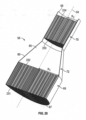
Figure 19 is an exploded perspective view of the air profile generator ofFigure 18 ; -
Figure 20 is a cross-sectional view of the air profile generator ofFigure 18 along section line A-A' inFigure 17 ; -
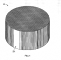
Figure 21 is an enlarged pictorial view of the upstream air flow collimator ofFigure 19 ; -
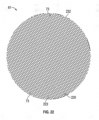
Figure 22 1 is a top view of the upstream air flow collimator of Figure 210; -
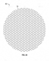
Figure 23 is a pictorial view of the downstream air flow collimator ofFigure 19 ; - Figure 243 is a top view of the downstream air flow collimator of
Figure 23 ; -
Figure 25 is a chart showing at the exit of the levitation device ofFigure 17 along section line A-A' onFigure 17 the velocity of the air flow in meters per second relative to the radial distance from a center axis; -
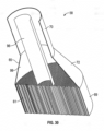
Figure 26 is a schematic pictorial view of an air profile generator in accordance with a ninth embodiment of the present invention in which a tubular air guide is shown as being transparent to assist in the illustration of a discharge outlet to extend coaxially through the air profile generator; -
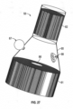
Figure 27 is a schematic pictorial view showing a tenth embodiment of an air profile generator in accordance with the present invention and in which a tubular air guide is shown as transparent; -
Figure 28 is a pictorial cross-sectional view of the air profile generator ofFigure 27 along section line C-C' inFigure 27 ; -
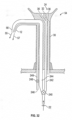
Figure 29 is a pictorial cross-sectional view of an air profile generator in accordance with an eleventh embodiment of the present invention; -
Figure 30 is a pictorial cross-sectional view of an air profile generator in accordance with a twelfth embodiment of the present invention; -
Figure 31 is a pictorial cross-sectional view of an air profile generator in accordance with a thirteenth embodiment of the present invention; and -
Figure 32 is a cross-sectional right side view of the hand cleaning assembly ofFigure 10 . - Reference is made first to
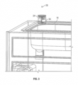
Figures 1 and2 , which show ahand cleaning station 10 in accordance with a first preferred embodiment of the invention. Thehand cleaning station 10 includes afaucet 12, a pair ofsinks 14, acabinet 16, and a handcleaner dispenser 18. The handcleaner dispenser 18 includes adrop discharge mechanism 20 also referred to as adispenser unit 20, an air delivery device such as anair pump 22, and alevitator device 24. Thedispenser unit 20 is similar to that disclosed inU.S. Patent No. 7,984,825 to Ophardt et al., issued July 26, 2011 , and inU.S. Patent No. 8,684,236 to Ophardt, issued April 1, 2014 . - The
dispenser unit 20 has areservoir 26 that contains hand cleaner fluid, such as hand soap or hand sanitizer. An electrically powered discharge mechanism of thedispenser unit 20 is operable to pump adrop 28 of the hand cleaner fluid from thereservoir 26 through anoutlet line 30 and out through adispenser outlet 32 of thelevitator device 24. The discharge mechanism is configured to pump a volume of air immediately following thedrop 28, preferably expelled with sufficient force to launch thedrop 28 from thedispenser outlet 32 to an airborne position where it can be caught and supported by an air cushion created by thelevitator device 24, as will be described in more detail below. The discharge mechanism may, for example, incorporate the pump as described inCanadian Patent Application Serial No. 2902751 to OP-HYGIENE IP GMBH , titled "Air Assisted Severance of Fluid Stream". - The
levitator device 24 is provided with aproximity sensor 34. Theproximity sensor 34 is configured to detect the presence of an individual standing in front of thehand cleaning station 10, and upon detecting the individual, trigger the activation of the discharge mechanism and thelevitation device 24. The sudden appearance of a levitatingdrop 28 of hand cleaner fluid will likely draw the attention of the individual, encouraging him or her to take the levitatingdrop 28. In alternative embodiments, the discharge mechanism andlevitator device 24 could be activated by any suitable trigger indicating a potential hand cleaning opportunity, such as the opening of thefaucet 12. - The
levitator device 24 is best shown inFigures 6 and7 as having a ring ofair outlets 36 which surround thedispenser outlet 32. Theair outlets 36 are fluidly connected byinternal channels 38 and anair outlet line 40 to theair pump 22. Theair pump 22 is activated in coordination with the discharge mechanism, and pumps air out through theair outlets 36 to create a cushion of air upon which the expelleddrop 28 floats. The circular arrangement ofair outlets 36 creates an area of reduced upwards air flow directly above thedispenser outlet 32. This causes thedrop 28 to sit stably in the center of the air cushion. Theair pump 22 may pump air by any suitable mechanism. For example, theair pump 22 could employ a ducted fan system or a supply of compressed air. Preferably, thelevitator device 24 is configured to expel air with a laminar flow. - The levitating
drop 28 is intended to attract the attention and interest of those nearby, and encourage them to clean their hands. The levitatingdrop 28 is located at a height above thecabinet 16 where it can be easily seen, and within reach of someone standing in front of the cleaningstation 10. To further attract attention, thedrop 28 could be made to rise up and down, by varying the velocity of the air expelled from theair outlets 36. Visual and/or auditory cues may also be used to draw attention to the levitatingdrop 28, and/or to provide directions for using the cleaningstation 10. For example, a recorded voice could prompt a user to take thedrop 28 with his or her hands. Thelevitator device 24 preferably incorporates a sensor which is able to detect when thedrop 28 has been taken by a user, which causes theair pump 22 to be turned off. - An alternate construction of the
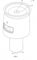
levitator device 24 in accordance with a second preferred embodiment of the invention is shown inFigure 8 , wherein like numerals are used to represent like components. Thelevitator device 24 shown inFigure 8 corresponds identically to the levitator device shown inFigure 6 , with the exception that the plurality ofcircular air outlets 36 have been replaced by asingle air outlet 36, formed as an annular slot surrounding thedispenser outlet 32. Theair outlet 36 serves as a nozzle to provide the necessary air flow to levitate thedrop 28. It is to be appreciated that theair outlets 36 could have any desired form, including, for example, a set of circular holes arranged in an annular array; an arrangement of one or more concentric annular slots; or a combination of circular holes and annular slots or slot segments. Theair outlets 36 together are to provide the necessary air flow to levitate thedrop 28. - Preferably, the viscosity and/or surface tension properties of the fluid are optimized to facilitate the stable levitation thereof. Generally, increasing viscosity and/or surface tension improves the stability of the levitating
drop 28, and reduces the likelihood that thedrop 28 will break apart during levitation. Preferably, the fluid has a higher viscosity than pure alcohol. More preferably, the fluid may have a viscosity and/or a surface tension at least equal to that of water and, more preferably, greater than the viscosity and/or a surface tension of water. Preferred fluids as hand cleaning fluids include liquid soaps and alcohol gels such as PURELL™ and Alco-Gel™ hand cleaners. As well, ozonized water may be used as the hand cleaning fluid, that is, water containing ozone gas in a sufficiently high concentration to disinfect the hands. Suitable fluids and composition for the fluids can be determined by empherical calculation and or by simple experimentation. - A further alternate construction of the levitating
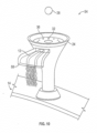
device 24 in accordance with a third preferred embodiment of the invention is shown inFigure 9 , wherein like numerals are used to represent like components. This construction of thelevitator device 24 incorporates anannular trap 42 for collecting unused hand cleaner. In particular, in a preferred manner of operation, if thedrop 28 is not taken after a predetermined amount of time, theair pump 22 is turned off, with thedrop 28 will fall back down onto thelevitator device 24. Thelevitator device 24 has a curved top surface which directs the unused hand cleaner into thetrap 42. The hand cleaner can then be drained away and disposed of, for example, through adrainage channel 43. Optionally, thedevice 24 could incorporate a self-cleaning function wherein water is periodically discharged into the levitation device to wash any unused hand cleaner collecting in thetrap 42 down thedrainage channel 43. For example, water from a water source could be delivered via a water delivery tube, not shown, to a levitation device a water outlet of thedispenser outlet 32 to wash the unused hand cleaner collecting in thetrap 42 down thedrainage channel 43. As another example, water from a water source could be delivered via thedispenser outlet 32 to wash the unused hand cleaner collecting in thetrap 42 down thedrainage channel 43. - In some embodiments of the invention, the
air outlets 36 are configured to alter the shape of the air cushion, for example, by reducing the air flow on one side of the ring, so as to direct the fallingdrop 28 toward thetrap 42 and away from thedispenser outlet 32 andair outlets 36. This helps to prevent theair outlets 36 and thedispenser outlet 32 from getting clogged with unused hand cleaner fluid. In other embodiments, theair outlets 36 and/ordispenser outlet 32 are configured to expel a blast of air that launches theunused drop 28 into anearby sink 14. In addition to saving energy, limiting the amount of time that adrop 28 is levitated before being discarded can help avoid a loss of efficacy (such as from alcohol evaporation), and help prevent any contamination which might occur if thedrop 28 is exposed to the external environment for an extended period of time. - In
Figure 9 , thedevice 24 has a clearouter shell 52 which surrounds thewaste trap 42. Several alternate shapes of theouter shell 52 are shown inFigures 9A, 9B and 9C , including inFigure 9A , a relatively closed arrangement; inFigure 9B , a partially open arrangement; and inFigure 9C , a fully open arrangement. In some embodiments of the invention, theouter shell 52 is removable and replaceable, so that any available shape could be selected as desired. In addition to aesthetic reasons, theouter shell 52 could also be selected for functional reasons, such as the extent to which a given shape protects the levitatingdrop 28 from the air currents that are present in the particular environment where thedevice 24 is installed. - A set of
LED lights 46 are also provided to illuminate the levitatingdrop 28 and/or to create a light display for drawing attention to thedevice 24. Thedevice 24 furthermore has arotating head 48, capable of full 360 degree motion, for further attracting attention thereto. Optionally, a color dye can be added to the hand cleaner fluid to increase the visibility of the levitatingdrop 28. Reflective particles could also be added to create a sparkling effect when light is directed onto thedrop 28. - A
hand cleaning assembly 54 in accordance with a fourth preferred embodiment of the invention is shown inFigures 10 and32 , wherein like numerals are used to represent like components. In this embodiment, thelevitator device 24 is combined with afaucet 12 and a handair drying mechanism 56 in a singleintegrated assembly 54. Themultifunctional assembly 54 permits hand washing, rinsing, and drying to be performed at a single, convenient location above asink 14. As in the previous embodiments, thelevitator device 24 discharges and levitates adrop 28 of hand cleaner fluid at a height where it can be easily seen and taken by a user's hand. The discharge and levitation of thedrop 28 can be triggered, for example, by a sensor which detects the user approaching thesink 14. Theassembly 54 preferably detects when thedrop 28 has been taken by the user, and automatically activates thewater faucet 12 to discharge from the water faucet outlet 13 a stream ofwater 57 for rinsing the user's hands. Next, the handair drying mechanism 56 is automatically activated to discharge from an air knife air outlet a stream ofair 55, preferably a high velocity stream of air, so that the user may conveniently dry his or her hands over thesink 14 by the air stream entraining and removing water on the user's hands. Theassembly 54 could also be automated to provide soap, water and air in a timed sequence, such as first providing a rinse phase where water is dispensed from thefaucet 12, followed by a scrub phase where thedrop 28 of hand cleaner is discharged and levitated, and then a second rinse phase followed by a final drying phase. Theassembly 54 could also be configured to accept user commands, such as voice commands or motion commands, to control the various functions thereof. Each of thelevitation device 24 and the handair drying mechanism 56 could have its own independent air delivery device. Preferably, anair delivery device 22 such as, for example, an air fan, could be provided to deliver a stream of pressurized air, and a switching orvalve mechanism 240 is provided to selectively deliver the stream of pressurized air to aconduit 242 leading to thelevitation device 24 or aconduit 244 leading to the handair drying mechanism 56. Water from awater source 246 is delivered via awater tube 249 to thefaucet 12 as controlled by acontrol valve 248. - A series of further alternate constructions of the
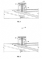
levitator device 24 in accordance with fifth, sixth, and seventh preferred embodiments of the invention are shown inFigures 11 to 16 , wherein like numerals are used to represent like components. These embodiments illustrate various modifications that may be made to thedevice 24 to enhance the functionality thereof. For example, thedevice 24 shown inFigures 13 and 14 incorporates adispenser outlet 32 that is raised above the ring ofair outlets 36. This configuration helps to ensure that the dischargeddrop 28 of hand cleaner is expelled at a sufficient height above the air cushion so as to be gently lifted and levitated thereby. - In the embodiment shown in
Figures 15 and 16 , an additional ring ofair outlets 36 has been added. By increasing the number ofair outlets 36, the properties of the air cushion can be further improved and controlled. For example, by discharging air from the outer ring ofair outlets 36 at a higher velocity than the inner ring, the air cushion can be shaped to more stably hold thedrop 28 in the center thereof. With a greater number ofair outlets 36, it also becomes possible to dynamically alter the shape of the air cushion during levitation, by independently controlling the velocity of the air that is expelled fromindividual air outlets 36 or sets ofair outlets 36. This can be used, for example, to move the levitatingdrop 28 along a path, such as a circle orfigure 8 , which may further attract attention to the levitatingdrop 28. - Reference is made to
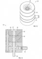
Figures 17 to 25 showing an eighth embodiment of afluid dispenser 18 in accordance with the present invention. As seen inFigure 17 and18 , thefluid dispenser 18 includes adrop discharge mechanism 20 and alevitator device 24. - The
levitator device 24 includes anair delivery device 22, and anair profile generator 58. Theair delivery device 22 is shown as afan 208 driven by anelectric motor 209 within a fan shroud 210. Pressurized air is delivered by theair delivery device 22 to aninlet 206 to theair profile generator 58 and passes through theair profile generator 58 and out anexit 207 of theair profile generator 58 as air flow with a profile that creates an air cushion to levitate afluid drop 28. - The
drop discharge mechanism 20 discharges adrop 28 of fluid through thedelivery tube 30 and out thedischarge outlet 32. As seen schematically inFigure 18 , theoutlet line 30 is shown to discharge adrop 20 at a velocity out of thedispenser outlet 32 directed radially into the air flow from theair profile generator 58 such that thedrop 20 may move radially to a position in which the air flow from theair profile generator 58 levitates the drop. -
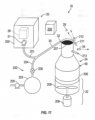
Figure 17 schematically shows thedrop discharge mechanism 20 as including adispenser 200 with afluid reservoir 26 and anelectric pump 21 to dispense a single dose of fluid through aplug discharge tube 201 in a manner as, for example, disclosed inU.S. Patent No. 8,684,236 to Ophardt, issued April 1, 2014 , the disclosure of which is incorporated herein by reference, such that the dose exits as a plug of fluid filling thedischarge tube 201 over a short length between both a upstream plug of air filling thedischarge tube 201 upstream from the liquid plug and a downstream plug of air downstream of the plug of fluid open to thedischarge outlet 32. Anair canon device 202 is provided having avessel 203 containing pressurized air connected via an airburst discharge tube 204 to theplug discharge tube 201. The airburst discharge tube 204 and plugdischarge tube 201 merge into thedelivery tube 30 leading to thedischarge outlet 32. Anair replenishing pump 205 is provided to keep the pressure of air within thevessel 203 within desired pressure ranges. Anair burst valve 206 is between thevessel 203 and thedelivery tube 30. Theair burst valve 206 is controllable to be open or closed. - In operation, the
dispenser 200 discharges a plug of fluid through theplug discharge tube 201 into thedelivery tube 30 and, once the plug of fluid is in thedelivery tube 30, theair burst valve 206 is quickly opened and then closed to deliver pressurized air from thevessel 203 through the airburst discharge tube 204 and into thedelivery tube 30 upstream from the plug of fluid in thedelivery tube 30. The pressurized air pushes the plug of fluid through thedelivery tube 30 and out thedispenser outlet 32 at a suitable discharge velocity. The plug of fluid on discharge out thedispenser outlet 32 into the air forms into thedrop 28. -
Figure 17 also schematically shows various sensors useful to control operation of the hand cleaningfluid dispenser 18. Referring toFigure 17 , thedispenser assembly 18 is schematically includes a number ofsensors control mechanism 209 to operate and control thedispenser assembly 18. InFigure 17 , aperson sensor 34 is provided to sense if a person is proximate to thedispenser assembly 20 and, preferably, to determine if a person is sufficiently close that the person may be able to reach a levitated drop with their hand or, if a person is at a distance, that the person may be attracted to thedispenser assembly 18 as by levitating a drop. Adrop sensor 211 is provided to sense if adrop 28 is being levitated. Ahand sensor 212 is provided to sense if a person's hand is passed through the locations where adrop 28 would be levitated towards providing an indication if adrop 28 may have been grasped by a user's hand. An air flow sensor 214 is provided to sense if there is air flow through theair profile generator 58 and, preferably, whether the air flow may be at a flow rate adequate for levitation. - As seen in
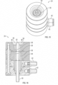
Figure 19 , theair profile generator 58 includes atubular air guide 60, an upstreamair flow collimator 61 and a downstreamair flow collimator 62. As best seen inFigure 20 , theair profile generator 58 and itstubular air guide 60 are each coaxial about anaxis 64. Thetubular air guide 60 has a radially inwardly directedinterior wall 65 coaxial about theaxis 64. Theair guide 60 is open at each of its axial ends to anair inlet 67 at an upstream end and to anair outlet 68 at a downstream end. Theair guide 60 has a cylindricalupstream portion 69 over which theinterior wall 65 is of a first radius R1 about theaxis 64 and a cylindricaldownstream portion 70 over which theinterior wall 65 is of a second radius R2 about theaxis 64 smaller than the first radius R1. Theair guide 60 also has an intermediate reducingportion 72 bridging between theupstream portion 69 and thedownstream portion 70. Over the reducingportion 72, the radius of theinterior wall 65 reduces gradually from the first radius R1 of theupstream portion 69 to the second radius R2 of thedownstream portion 70 with proximity to thedownstream portion 70. In the ninth embodiment, the reducingportion 72 is shown to be frusto-conical, however, while this is preferred, it is not necessary. - The upstream
air flow collimator 61 is best seen in pictorial views inFigures 19 and21 and in top view inFigure 22 . The upstreamair flow collimator 61 provides a plurality of parallel straight-throughupstream passageways 73 for air flow. Eachupstream passageway 73 extends parallel to theaxis 64. Eachupstream passageway 73 is open at both axial ends, that is, open both at an axialupstream inlet end 231 of the upstream air flow collimator and an axiallydownstream exit end 232 of the upstreamair flow collimator 61. In the preferred embodiment as illustrated, the upstream air flow collimator is formed with a honeycomb construction providing each of thepassageways 73 to be hexagonal in cross-section with each of itsside walls 233 forming an adjacent side wall of anadjacent passageway 73. The upstreamair flow collimator 61 is seen as a plug of the honeycomb material which has cylindricalouter surface 221 engaged with thewall 65 of the cylindrical upstream portion 69 of theair guide 60. As seen inFigure 18 , the upstreamair flow collimator 61 is shown to provide the upstream inlet ends 231of thepassageways 73 in an upstream plane normal to theaxis 64 and the downstream exit ends 232 of thepassageways 73 in a downstream plane also parallel theaxis 64. Providing the upstream inlet ends and the downstream exit ends of thepassageways 73 to be in the same plane normal theaxis 64 is not necessary and these ends may be provided in other planes normal theaxis 64 such as, for example, frusto-conical about theaxis 64, or otherwise varying with radial distance from theaxis 64. - The downstream
air flow collimator 62 is shown to be substantially identical to the upstreamair flow collimator 61 as a cylindrical plug of honeycomb material which closely engages thewall 65 within the cylindricaldownstream portion 70 of theair guide 60. The downstreamair flow collimator 62 has a plurality of parallel straight-throughdownstream passageways 74 for air flow. Eachdownstream passageway 74 extends parallel to theaxis 64. Eachdownstream passageway 74 is open axially at each of its ends, that is, open axially at anupstream inlet end 233 and open axially at adownstream outlet end 234. The inlet ends 233 of thedownstream passageways 74 are shown to lie in a flat plane normal to theaxis 64. The exit ends 234 of thepassageways 74 are shown to lie in a flat plane normal to theaxis 64. This is not necessary and the inlet and outlet ends of thepassageways 74 may be provided in other configurations such as with varying axial position relative to the distance from theaxis 64, for example, to be frusto-conical. The center of any frusto-conical portion of the plane containing the inlet ends or exit ends of either thepassageways -
Figure 18 schematically illustrates thelevitator device 24 as having theair delivery device 22 for delivering a stream of pressurized air to theair inlet 67 of theair guide 60 for passage of the air through the upstreamair flow collimator 61 via itspassageways 73, through the reducingportion 72 constrained by theinterior wall 65 and through thedownstream airflow collimator 62 to exit from theair outlet 68 of thetubular air guide 60. - On
Figure 18 , thedrop 28 is shown as being ejected at a velocity out of thedispenser outlet 32 to adopt the path as shown with the drop in broken lines into a levitating air cushion provided by the air being discharged from the outlet of theair guide 60. OnFigure 18 , two drops 28 are shown one in solid lines and the second in broken lines to schematically illustrate upper and lower limits of a suitable range of heights at which thedrop 28 may be levitated above thelevitator device 24 at heights and positions where thedrop 20 is accessible to be grasped by a hand of a user. - Reference is made to
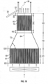
Figure 25 which shows a chart measuring at theair outlet 68 of thetubular air guide 60 ofFigure 18 , the velocity of the air flow in meters per second relative to the radial distance from theaxis 64 as measured in the vertical cross-sectional plane A-A' inFigure 17 including thecenter axis 64. As can be seen inFigure 25 , the upwardly directed flow of air has avelocity profile 80 disposed about theaxis 64 with acenter portion 81 and anannular portion 82 annularly relative the axis about thecentral portion 81. Over thecentral portion 81, the flow of air has a velocity adequate to levitate thedrop 20 above thecentral portion 81. Over theannular portion 82, the velocity is greater than the velocity over thecentral portion 81. Thevelocity profile 80 shown inFigure 25 would appear substantially the same in any vertical plane including theaxis 64 at any rotational position about theaxis 64. - As can be seen on
Figure 25 , theannular portion 82 has anannular peak 83 representing the highest velocity. Theannular portion 82 has anannular shoulder segment 84 between theannular peak 83 and thecentral portion 81 within whichannular shoulder segment 84 the air velocity decreases with a reduction in the radial distance from theaxis 64. Adrop 28 which is within theannular shoulder segment 84 of the air flow will be directed partially radially inwardly towards theaxis 64 as well as vertically upwardly, with the radial component by which the drop is directed moving thedrop 28 radially towards thecentral axis 64 and thus over to thecentral portion 81. - The velocity of the air flow from the
exit 68 of thetubular air guide 60 will decrease with axial distance upwardly from theoutlet 68 of thetubular air guide 60. The velocity of thecenter portion 81 must, on one hand, maintain a minimum velocity in order to keep thedrop 28 in a levitated condition. This minimum velocity depends upon the specific material and volume of the drop amongst other factors. The decrease in velocity of air flow in the axial direction of air flow will provide for the drop to be levitated within a range of heights above theair exit 68 of theair guide 60. Each drop is levitated by being maintained above thecentral portion 81 constrained in respect of radial movement by the velocity profile over theannular shoulder segment 84 and in respect of vertical movement by the decreased velocities over the entire air flow with increased distance of above theexit 68 of theair guide 60. - The chart of
Figure 25 represents experimental data from air flow through an air profile generator as shown inFigure 18 with the following specifications. The cylindrical upstream portion and of theupstream collimator 61 was 200 ml. The height of the cylindricalupstream portion 69 H1 and the height of CH1 of the upstream collimator was each 100 milliliters. The second radius R2 of the cylindricaldownstream portion 70 and the downstream collimator was 100 milliliters. The height CH2 of thedownstream collimator 62 was 100 milliliters. The height H2 of the cylindricaldownstream portion 70 was 125 millimeters. The inlet spacing IS2 of thedownstream collimator 62 from the inlet to the cylindricaldownstream portion 70 was 12.5 centimeters and the exit spacing ES2 of the exit of thedownstream collimator 62 from the exit of the cylindricaldownstream portion 70 was 12.5 millimeters. The height R3 of the reducingportion 72 was 100 millimeters. Theupstream collimator 61 has the same height CH1 as the height H1 of the cylindricalupstream portion 69 with the result that the inlet spacing IS1 and the exit spacing ES1 are both equal to zero. An angle A between a plane normal theaxis 64 and the frusto-conical side wall of the reducingportion 72 is 65 degrees. The diameter of each of thepassageways - The
air profile generator 58 may have many different combination of dimensions. For example, in anair profile generator 58 as shown inFigure 18 , preferred ranges for the diameter of thepassageways upstream collimator 61 are 0 millimeter to 5,000 millimeters and, for thedownstream collimator 62, the height CH2 may be in the range of 0 millimeter to 200 millimeters, for example. Ranges for the radius R1 may be in the range of 5,000 to 50 millimeters. Preferred ranges for the second radius R2 is in the range of 10 to 200 millimeters. Preferred ranges for such angles are in the range of 10 degrees to 170 degrees and, more preferably, is 65 degrees. - The
levitator device 18 is preferably operated to levitate a fluid droplet of a diameter of in the range of 70 mm to 200 mm, more preferably, 80 mm to 120 mm, more preferably, 80 mm to 100 mm. Preferably, the drop diameter is at least 70 mm and, more preferably, at least 80 mm or 90 mm. Preferably, the drop volumes are in the range of 0.2 ml to 3 ml and, more preferably, in the range of 0.2 ml to 0.7 ml. With exit air velocities from theair profile generator 58 in the range of 6 to 10 meters per second with the fluid being an alcohol hand sanitizer, for example, the PURELL™ and Alco-Gel™ hand cleaners preferred drops have volumes in the range of 0.2 ml to 0.4 ml for alcohol gel hand sanitizers. For liquid hand soaps, preferred drop volumes are between 0.2 ml and 0.5 ml. More preferably, exit air velocities are in the range of 7 to 8 meters per second for typical hand cleaning fluids. - In one preferred unclaimed method of operation, the dispense assembly is operated to sense the presence of a user and, while the user is present, and the first drop being levitated to conduct a first monitoring to indicate whether or not the first drop is at a height above the levitator within a range of positions where a drop is accessible to be taken by a user's hand. When the monitoring is performed such that while the user is sensed to be proximate the drop to be levitated and a first monitoring indicates that a first drop was at a height above the apparatus within the range of positions where the drop is accessible to be taken by a user followed by conducting of a second monitoring indicating that the first drop is not at a height above the levitator, this series of events can be taken to be assumed as an indication that the first drop was taken by the user's hand. Promptly after the second monitoring indicating that the first drop is not present, the apparatus is preferably activated to promptly eject and levitate a subsequent drop, preferably within a tome of not greater than half a second. The apparatus is monitored so as to repeat the steps thus subsequently monitoring whether or not the next subsequent is a height above the levitator and where the monitoring indicates the next drop was levitated above the monitor followed by a second monitoring indicating that the subsequent drop is not above the levitator, then promptly levitating a yet further subsequent drop. These series of steps are preferably repeated until an accumulative volume of the first drop and each subsequent drop represents a pre-determined volume suitable to be grasped by a user's hand for a pre-determined use of the fluid. For example, that an advantageous pre-determined volume of the fluid for use in cleaning the hands has been dispensed. For example, with an alcohol gel type alcohol based hand cleaning fluid and each individual drop of 2 ml, on a user approaching the dispenser assembly and grasping a first drop, after the first drop is monitored as having been sensed, two, three or four additional drops would in quick succession be dispensed such that the user will be inclined to grasp the 3 to 5 drops receiving a total volume of, for example, .6 to 1.0 mg. Similarly, for any other hand fluid, the dispensing apparatus may be operated in a manner that, after a first drop has been taken by a user, a quick succession of successive additional drops may be levitated to be taken until an accumulative volume of the fluid has been taken representing a pre-determined volume of liquid suitable for a preferred use. Rather than monitor the presence of a drop being levitated or not, the swiping or movement of the user's hand through where a drop is levitated could be used as an indication that a drop has been taken by a user. Both monitoring of the presence or absence of a levitated drop and he movement of a user's hand could be used toward determining when to discharge and levitate a successive drop.
- In accordance with the dispenser devices of the present invention, a drop is levitated for a period of time at a height above the levitator device within a range of positions where the drop is accessible to be taken by a user's hand. Preferably, the range of positions where the drop is accessible to be taken by a user's hand permits a drop to be grasped by the user's hand without the user's hand engaging anything other than the drop and, of course, the atmospheric air within which the drop is levitated. Preferably, therefore, the drop will be levitated at least one and, more preferably, at least two or four centimeters above the dispenser apparatus with the dispenser apparatus providing a free vertical space in the range of 10 to 15 cm within which a user's hand may be moved horizontally through an open space above the dispenser apparatus to grasp a drop without engaging anything other than the drop and the air through which the user's hand is moved. Preferably, the grasping space above the apparatus device will have a height in the range of at least 15 cm, a width of at least 15 cm, more preferably at least 40 cm and a depth measured radially from the drop about a vertical axis of at least about 7.5 cm, more preferably 20 cm. Such a grasping space will be useful to ensure that the user's hand does not engage any matter other than the drop in the air within which it is levitated such that the dispenser apparatus will be touchless and minimizes any cross contamination.
- Such that a user may grasp a preferred minimum volume of the fluid to be levitated, the drops of the fluid may be levitated in quick succession to an individual user after it is determined that the user has grasped a first drop. Alternatively, a plurality of drops may be levitated at the same time. A plurality of drops may be levitated, for example, by providing the air cushion to, for example, move the individual drops through a circular pattern so as to minimize the likelihood that the individual drops will engage each other and collate into a drop which either will not be levitated and will, due to the air velocity, disintegrate.
-
Figures 17 and18 show the introduction of thedrop 28 radially into the air flow from theair profile generator 58. However, there are many different manners in which thedrop 20 may be suitably located within the air cushion provided by the upwardly flowing air from theair profile generator 58, for example, axially from below or above. - Reference is made to
Figure 26 which illustrates anair profile generator 58 identical to that inFigure 19 but for two exceptions. InFigure 26 , thetubular air passage 60 is shown as being transparent for ease of illustration. A first exception is that afirst outlet line 30 is shown as being provided to extend coaxially along theaxis 64 through each of theupstream collimator 61 and thedownstream collimator 62 so as to locate thedischarge outlet 32 within the upwardly extending air flow at the outlet end of thetubular air guide 60 and to discharge adrop 28 upwardly into the air flow. A second exception is thatFigure 26 also shows in broken lines analternate outlet line 30 to dispense thedrop 28 from adispenser outlet 32 disposed coaxially of theaxis 64, however, at a height vertically above the outlet of theair guide 60 such that adrop 20 may be discharged to fall vertically downwardly into the levitating air cushion provided by the upward flowing air. The particular manner by which a drop of liquid is directed to become located within the levitating cushion of air is not limited. - Reference is made to
Figures 27 and28 showing a tenth embodiment of anair profile generator 58 in accordance with the present invention. InFigures 27 and28 , thetubular air passage 60 is shown as being transparent for ease of illustration. Theair profile generator 58 ofFigure 27 is identical to theair profile generator 58 ofFigure 19 but for three exceptions. A first exception is the provision ofair flow blocker 86. The second exception is the provision of apressure dampening mechanism 87. A third exception is the provision of an acoustical dampeningmechanism 88. - The
air flow blocker 86 comprises a thin circular disc coaxially about theaxis 64 which is secured to theexit end 232 of the upstreamair flow collimator 61 to stop flow through thepassageway 73 covered by theair flow blocker 86. Theair flow blocker 86 thus prevents air flow over a selected central circular portion through the upstreamair flow collimator 61 as can be advantageous to assist in providing for a reduced velocity over thecentral portion 81 of the velocity profile. Theair flow blocker 86 is illustrated as a circular disc closing the exit ends of selected of the passageways 39, alternate configurations forair flow blockers 86 could be provided at the inlet ends 231 of thepassageways 73 of the upstreamair flow collimator 61 or within the reducingportion 72 at some distance from theupstream air collimator 61. - The
pressure dampening mechanism 87 is provided to dampen changes in air pressure within theair guide 60 and, more preferably, within the reducingportion 72 of theair guide 60. Thepressure dampening mechanism 87 is shown as comprising a resilientspherical balloon 89 with aneck 90 that is fixedly secured about anopening 91 through thewall 65 of theair guide 60 into the reducingportion 72. Theballoon 89 defines a variable volume compartment 92 in communication with the air within the reducingportion 72. The variable volume compartment 92 is defined within the confining walls of theballoon 89 so as to be resilient in the sense of having a resilient panel with an inherent bias to adopt an inherent condition in which the compartment 92 has an inherent volume. The resilient panel resiliently stretches from its inherent condition to biased conditions in which the compartment 92 adopts biased volumes greater than the inherent volume as the air pressure in the compartment 92 increases. Insofar as there is an increase in air pressure within the reducingportion 72, then this will provide an increase in pressure within theballoon 89 increasing the volume of theballoon 89 which will have an effect of reducing the air pressure within the reducingportion 72. The particularindividual balloon 89 illustrated is but a simplified configuration of such an airpressure dampening mechanism 87. The relative volume of the variable volume compartment 92 will have an impact on the extent to which dampening of the air pressure within theair profile generator 58 may be carried out.Individual balloons 89 may have a capability to expand to a relatively substantial volume during normal operational pressures of theair profile generator 58 and, as well, a plurality of suchpressure dampening mechanisms 87 may be provided annularly about theair guide 60. Rather than provideexternal balloons 89 as illustrated inFigure 27 , a similar dampening arrangement could be provided by having an inflatable annular bladder about the reducingportion 72 with a plurality of openings through the wall into the resilient annular bladder. - On
Figure 27 , an acoustical dampeningmechanism 88 is schematically shown as comprising an acoustical speaker94 so as to direct sound waves through an array ofopenings 95 in thewall 65 and into the interior of theair guide 60 preferably into the interior of the reducingportion 72 so as to interfere with and thereby reduce air flow patterns such as standing waves and the like that may arise due to air flow through theair guide 60 the interior of the reducingportion 72. - Reference is made to
Figure 29 which illustrates a pictorial cross-sectional view of anair profile generator 58 in accordance with an eleventh embodiment of the present invention which is identical to theair profile generator 58 shown inFigure 19 but for the inclusion of a cylindrical tubular innerguide tube member 96 with an axially openupstream end 97 and an axially opendownstream end 98. Thetube member 96 extends axially through reducingportion 72. The tube member 92 is coaxial about theaxis 64. The tube member 92 has a radius less than the second radius R2 of thedownstream portion 70 so as to define within theair guide 60 annularly about the tube member 92 an annular passage 999 for air flow. As seen inFigure 29 , thetube member 96 extends within the reducingportion 72 between theupstream collimator 61 and thedownstream collimator 62. Theannular passage 99 for air flow is defined radially outwardly of thetube member 96 and radially inwardly of thewall 65. The cross-sectional area of theannular passage 96 normal to theaxis 64 reduces with proximity to the exit end 68 of theair guide 60 thus increasing air pressure within theannular passage 99 proximate the inlet of thedownstream collimator 62 and hence giving rise to air flow through thepassageways 74 of thedownstream collimator 62 that are open to theannular passage 99 to be increased compared to the velocity of air flow through thepassageways 74 that receive air flow that passes radially inside theguide tube member 96. - In the first preferred embodiment, the present invention as illustrated in
Figure 19 , both anupstream collimator 61 and adownstream collimator 62 are provided. In accordance with the present invention, the provision of the downstreamair flow collimator 62 may be eliminated such that anair profile generator 58 may be provided which is the same as that illustrated inFigure 19 as a further embodiment in which there is provided merely thetubular air guide 60 and the upstreamair flow collimator 61. - Reference is made to
Figure 30 which illustrates a pictorial cross-sectional view of anair profile generator 58 in accordance with the present invention which has close similarities to theair profile generator 58 of the eleventh embodiment ofFigure 29 . InFigure 30 , the downstreamair flow collimator 62 has been eliminated compared to that inFigure 29 and atubular air guide 96 provided similar to that inFigure 29 but extended so as to extend coaxially through the cylindricaldownstream portion 72. InFigure 30 , theannular passage 99 for air flow is provided between theguide tube member 96 and thewall 65 axially through the cylindricaldownstream portion 70 and the reducingportion 72. In the embodiment ofFigure 30 , the coaxial arrangement of thewall 65 over the cylindricaldownstream portion 70 and thetube member 96, in effect, provide a downstream air flow collimator. - Reference is made to
Figure 31 which illustrates anair profile generator 58 in accordance with a thirteenth embodiment. Theair profile generator 58 inFigure 31 has similarities to theair profile generator 58 ofFigure 30 , however, modified so as to eliminate the upstreamair flow collimator 61 inFigure 30 and to extend theguide tube member 96 so that it passes annularly through the cylindricalupstream portion 69 as well as through the cylindricaldownstream portion 70 and the reducingportion 72. Within the cylindricalupstream portion 69, thecylindrical wall 65 and the cylindrical tubular innerguide tube member 96 effectively form an air flow upstream collimator. - Preferably, an unclaimed method comprises levitating the drop at heights above the levitator device with an array of positions where the drop is accessible to be taken by a user's hand and the levitation is for some reasonable period of time that will permit the drop to actually be taken by a user's hand. In this context, as seen, for example, in
Figure 3 , thedrop 28 is levitated above thelevitator device 24 at a location where the drop is accessible to be grasped by the hand of a user as, for example, the user's hand being moved horizontally as in a swipe to grasp thedrop 28 with the user's hand. In the unclaimed method of operating, thedrop 28 may be levitated at varying heights within the air cushion as the air cushion may vary with time albeit with thedrop 28 being maintained at the positions where the drop can be taken by a user's hand. - Preferably, the
drop 28 is levitated for a period of time adequate to permit a user to see the drop and to then take the drop with a user's hand. Preferably, this period of time may be at least one second although, more preferably, the period of time may be two, three or four seconds or a relatively considerable period of time such as, for example, twenty, thirty or sixty seconds or more. After an individual drop has been levitated for a period of time then, preferably, the levitation is stopped as, with time, some drops will come to have reduced mass and may be ejected. - In accordance with the present invention, the device may be operated in accordance with a unclaimed method so that while levitating the first drop, a second drop is levitated to also be accessible to be taken by a user's hand. Thus, two or more drops may be levitated at the same time. Depending upon whether the drops have the same size or mass, the drops may in fact be levitated as independent drops. The levitating of two independent drops could be accomplished with each of the drops dispensed from a
different outlet 32 with, for example, no mixing of the liquids of the two drops to mix until such time as the drops are grasped by the hand of a user. Alternatively, where two drops of different materials are desired to be mixed in a user's hand, it may be possible to discharge a first drop to be grasped by a user and only then to discharge a second drop to be levitated and grasped by a user. - In accordance with a preferred operation of the dispenser, a person sensor is provided so as to sense when a user is proximate to the dispenser as, for example, within a few feet of the dispenser albeit not so close to the dispenser as to have a typical user grasp a drop with the user's hand. The dispenser may be operated on the approach of such a user with the intention of enticing the user's interest and to draw the user towards the device due to their interest or curiosity such that the user may take the drop. The person sensor or another sensor may be provided so as to provide an indication whether or not a user is sufficiently close to the dispenser that a typical user could take the drop with a user's hand. A drop sensor may preferably be provided so as to give an indication as to whether or not at any time there is a drop being levitated. Provision of one or more of these sensors can provide for advantageous operation of the dispenser in a number of manners. For example, after a drop is levitated, the sensor sensing whether or not a drop is levitated will discontinue providing the air flow if a signal is provided that no drop is being levitated. The fact that no drop is being levitated could arise, for example, by a drop that is ejected and not being levitated or by a user's hand grasping a drop. A hand sensor could be provided to determine whether or not a user's hand is moved through the air cushion in a manner that might remove a drop. Such a hand sensor to sense a hand moving through the air cushion might be more readily able to determine the expected removal of a levitated drop as contrasted with attempting to merely sense whether a drop continues to be levitated. After any drop is levitated, the device could be operated so as to discontinue air flow after a period of time. If there is a drop being levitated when air flow is to be stopped then, preferably, the device is operated to control levitation of the drop to cause the drop to descend downwardly towards a collection vessel on the dispenser.
- In accordance with the preferred embodiments illustrated in
Figure 19 , thetubular air guide 60 includes the cylindricalupstream portion 69, the intermediate reducingportion 72 and a cylindricaldownstream portion 70. It is to be appreciated that insofar as the reducingportion 72 is provided so as to connect the exit end of the upstreamair flow collimator 61 to the inlet end of the downstreamair flow collimator 62, there is no need for the cylindricalupstream portion 69 or the cylindricaldownstream portion 70. Insofar as the cylindricalupstream portion 69 and the cylindricaldownstream portion 70 are provided, then the intermediate reducingportion 72 may be considered a connectingshroud 72 providing an internal guide passageway extending between the exit end of the upstream air flow collimator and the inlet end of downstream air flow collimator. - The
air profile generator 58 as shown inFigure 19 provides an internal guide passageway for air flow coaxially therethrough with a guide passageway having at each point along the axis 64 a cross-sectional area normal to the axis. As can be seen, the cross-sectional area of the guide passageway normal to the axis does not increase from the exit end of the upstreamair flow collimator 61 to the inlet end of the downstreamair flow collimator 62. Over the intermediate reducingportion 72, the cross-sectional area of the guide passageway normal the axis reduces gradually with proximity to the inlet to the downstreamair flow collimator 62. - It will be understood that, although various features of the invention have been described with respect to one or another of the embodiments of the invention, the various features and embodiments of the invention may be combined or used in conjunction with other features and embodiments of the invention as described and illustrated herein.
- It is to be appreciated that the term "hand cleaner fluid" as used herein is intended to refer broadly to any hand cleaning substance that is capable of being levitated, including for example, liquid soaps, liquid sanitizers, gels, creams, foams, capsules, and composite materials.
- It is to be appreciated that the hand
cleaner dispenser 18 of the present invention need not have the specific constructions that have been shown and described in the preferred embodiments. Rather, any alternate constructions that are able to provide a levitating allotment of hand cleaner fluid could be used. - The
device 24 may, for example, incorporate one or more features of the aerodynamic levitation device disclosed inUnited States Patent No. 5,215,688 to Williamson et al., issued June 1, 1993 . - While a hand
cleaner dispenser 18 has been described as being installed beside asink 14 andfaucet 12, it is to be appreciated that thedispenser 18 could be installed on its own as a standalone unit. - Although this disclosure has described and illustrated certain preferred embodiments of the invention, it is to be understood that the invention is not restricted to these particular embodiments. Rather, the invention includes all embodiments which are functional or mechanical equivalents of the specific embodiments and features that have been described and illustrated herein.
Claims (11)
- A fluid dispenser (18), comprising:a reservoir (26) for containing fluid to be dispensed;a dispenser outlet (32) for discharge of the fluid from the reservoir (26);a discharge mechanism (20) operable to discharge a drop (28) of the fluid from the dispenser outlet (32) when activated; anda levitator device (24) operable to levitate the drop (28) of the fluid where the drop (28) is accessible to be taken by a user's hand;wherein the levitator device (24) is an aerodynamic levitator device (24) providing an upwardly directed flow of air to levitate the drop (28);characterized in that the fluid dispenser (18) further comprises:a sensor (34) that senses when a user is proximate to where the drop (28) is to be levitated;wherein on sensing the user to be proximate to where the drop (28) is to be levitated, the levitator device (24) levitates the drop (28) where the drop (28) is accessible to be taken by the user's hand; andwherein the fluid includes one or more of a skin cleaner, a skin moisturizer, a skin disinfectant, a skin medication, an insect repellant and a skin perfume.
- The fluid dispenser (18) according to claim 1, wherein the upwardly directed flow of air levitates the drop (28) for a period of time at a height above the levitator device (24) within a range of positions where the drop (28) is accessible to be taken by the user's hand;wherein the period of time is at least one second; andwherein the range of positions permits the drop (28) to be grasped by the user's hand without the user's hand engaging anything other than the drop (28) and air within which the drop (28) is levitated.
- The fluid dispenser (18) according to claim 1 or claim 2, wherein:the upwardly directed flow of air has a velocity profile (80) disposed about a central vertical axis (64) with a central portion (81) of the velocity profile (80) and an annular portion (82) of the velocity profile (80) annularly relative the axis (64) about the central portion (81),the central portion (81) of the velocity profile (80) having a velocity to levitate the drop (28) above the central portion (81),the annular portion (82) of the velocity profile (80) having a velocity greater than the velocity of the central portion (81),the velocity of the annular portion (82) selected to direct a drop (28) within the annular portion (82) of the velocity profile (80) adjacent the central portion (81) of the velocity profile (80) radially toward the central vertical axis (64).
- The fluid dispenser (18) according to claim 3, wherein the velocity of the annular portion (82) adjacent the central portion (81) of the velocity profile (80) decreases with reduced radial distance from the axis (64).
- The fluid dispenser (18) according to claim 3, wherein the levitator device (24) has an air inlet (67) and an air outlet (68),
the levitator device (24) comprising:an upstream air flow collimator (61) extending longitudinally along the axis (64) from the air inlet (67) at an inlet end (231) to an exit end (232), a plurality of parallel straight-through upstream passageways (73) for air flow through the upstream air flow collimator (61) from the inlet end (231) to the exit end (232), each upstream passageway (73) extending parallel to the axis (64),a downstream air flow collimator (62) extending longitudinally along the axis (64) from an inlet end (233) to an exit end (234) open at the air outlet (68), a plurality of parallel straight-through downstream passageways (74) for air flow through the downstream air flow collimator (62) from the inlet end (233) to the exit end (234), each downstream passageway (74) extending parallel to the axis (64),a connecting shroud (72) providing an internal guide passageway extending longitudinally along the axis (64) from the exit end (232) of the upstream air flow collimator (61) to the inlet end (233) of the downstream air flow collimator (62) guiding the air exiting from the exit end (232) of the upstream air flow collimator (61) to the inlet end (233) of the downstream air flow collimator (62),the guide passageway having at each point along the axis (64) a cross-sectional area of the guide passageway normal to the axis (64),the cross-sectional area of the guide passageway normal to the axis (64) not increasing from the exit end (232) of the upstream air flow collimator (61) to the inlet end (233) of the downstream air flow collimator (62),the guide passageway having a reducing portion (72) extending longitudinally along the axis (64) over which the cross-sectional area of the guide passageway normal to the axis (64) reduces gradually with proximity to the inlet end (233) of the downstream air flow collimator (62). - The fluid dispenser (18) according to claim 5, wherein the levitator device (24) further comprises:an air delivery device (22) for delivering a stream of pressurized air to the air inlet (67); anda pressure dampening mechanism (87) to dampen changes in air pressure within the reducing portion (72);wherein the pressure dampening mechanism (87) is open to the reducing portion (72); andwherein the pressure dampening mechanism (87) comprises a variable volume compartment (92) in communication with the reducing portion (72), the compartment (92) defined within a confining wall having a resilient panel having an inherent bias to adopt an inherent condition in which the compartment (92) has an inherent volume and which resilient panel resiliently stretches from its inherent condition to biased conditions in which the compartment (92) has biased volumes greater than the inherent volume as the air pressure in the compartment (92) increases.
- The fluid dispenser (18) according to claim 6, wherein the levitator device (24) has a plurality of air outlet openings (36) for providing the upwardly directed flow of air to levitate the drop (28);wherein the outlet openings (36) are annularly arranged around the dispenser outlet (32), and the dispenser outlet (32) is configured to discharge the drop (28) of fluid upwards into the upwardly directed flow of air;wherein the annularly arranged outlet openings (36) form at least two concentric rings, including an inner ring that is proximate to the dispenser outlet (32) and an outer ring that is distal from the dispenser outlet (32);wherein the outlet openings (36) of the outer ring expel air at a greater velocity than the outlet openings (36) of the inner ring;the fluid dispenser (18) further comprising:a water outlet (13) operable to dispense water (57) onto the user's hand;an air discharge chute to receive the stream of pressurized air and deliver it as an exit stream for drying the user's hand; anda valve (240) to selectively direct the stream of pressurized air from the air delivery device (22) to either the levitator device (24) or the air discharge chute.
- The fluid dispenser (18) according to any one of claims 1 to 7, further comprising a drop sensor (211) that monitors whether the drop (28) is being levitated where the drop (28) is accessible to be taken by the user's hand.
- The fluid dispenser (18) according to any one of claims 1 to 7, further comprising a drop sensor (211) that monitors whether the drop (28) is being levitated where the drop (28) is accessible to be taken by the user's hand;
wherein, while the user is sensed to be proximate to where the drop (28) is to be levitated:(i) the drop sensor (211) monitors whether the drop (28) is being levitated where the drop (28) is accessible to be taken by the user's hand; and(ii) the levitator device (24) repeatedly levitates successive drops (28) of the fluid whenever the drop sensor (211) senses that the drop (28) is not being levitated where the drop (28) is accessible to be taken by the user's hand. - The fluid dispenser (18) according to claim 9, wherein (i) and (ii) continue until a cumulative volume of the fluid discharged from the dispenser outlet (32) reaches a predetermined volume suitable for a predetermined use of the fluid.
- The fluid dispenser (18) according to any one of claims 1 to 10, wherein the fluid comprises a hand cleaning fluid.
Applications Claiming Priority (2)
| Application Number | Priority Date | Filing Date | Title |
|---|---|---|---|
| US201562259529P | 2015-11-24 | 2015-11-24 | |
| EP16200532.6A EP3173001B1 (en) | 2015-11-24 | 2016-11-24 | Levitation fluid dispenser |
Related Parent Applications (2)
| Application Number | Title | Priority Date | Filing Date |
|---|---|---|---|
| EP16200532.6A Division EP3173001B1 (en) | 2015-11-24 | 2016-11-24 | Levitation fluid dispenser |
| EP16200532.6A Division-Into EP3173001B1 (en) | 2015-11-24 | 2016-11-24 | Levitation fluid dispenser |
Publications (3)
| Publication Number | Publication Date |
|---|---|
| EP3473149A1 EP3473149A1 (en) | 2019-04-24 |
| EP3473149A8 EP3473149A8 (en) | 2019-06-19 |
| EP3473149B1 true EP3473149B1 (en) | 2023-04-12 |
Family
ID=57394480
Family Applications (2)
| Application Number | Title | Priority Date | Filing Date |
|---|---|---|---|
| EP18207549.9A Active EP3473149B1 (en) | 2015-11-24 | 2016-11-24 | Levitation fluid dispenser |
| EP16200532.6A Active EP3173001B1 (en) | 2015-11-24 | 2016-11-24 | Levitation fluid dispenser |
Family Applications After (1)
| Application Number | Title | Priority Date | Filing Date |
|---|---|---|---|
| EP16200532.6A Active EP3173001B1 (en) | 2015-11-24 | 2016-11-24 | Levitation fluid dispenser |
Country Status (3)
| Country | Link |
|---|---|
| US (1) | US10244901B2 (en) |
| EP (2) | EP3473149B1 (en) |
| CA (1) | CA2949483A1 (en) |
Families Citing this family (3)
| Publication number | Priority date | Publication date | Assignee | Title |
|---|---|---|---|---|
| WO2019195536A1 (en) * | 2018-04-06 | 2019-10-10 | Gojo Industries, Inc. | Foam-at-a-distance dispensing systems |
| USD886240S1 (en) | 2018-04-26 | 2020-06-02 | Bradley Fixtures Corporation | Faucet and soap dispenser set |
| USD886245S1 (en) | 2018-04-26 | 2020-06-02 | Bradley Fixtures Corporation | Dispenser |
Family Cites Families (18)
| Publication number | Priority date | Publication date | Assignee | Title |
|---|---|---|---|---|
| US2281051A (en) * | 1940-05-20 | 1942-04-28 | Albert J Roger | Drop meter and dispenser |
| US4278206A (en) | 1979-04-13 | 1981-07-14 | Ae Development Corporation | Non-pressurized dispensing system |
| US5215688A (en) | 1991-04-12 | 1993-06-01 | Vanderbilt University | Apparatus and method for aerodynamic levitation |
| US5890580A (en) * | 1993-07-12 | 1999-04-06 | Kaijo Corporation | Object levitating apparatus, object transporting apparatus, and object levitating bearing along with an object levitating process and object transporting process |
| JP3300145B2 (en) * | 1993-12-24 | 2002-07-08 | 株式会社カイジョー | Object levitation device |
| JPH07275690A (en) | 1994-04-05 | 1995-10-24 | Mitsubishi Electric Corp | Flotation apparatus |
| US6168638B1 (en) * | 1998-04-24 | 2001-01-02 | Ball Semicondutor, Inc. | Touchless stabilizer for processing spherical shaped devices |
| US6045341A (en) | 1998-07-14 | 2000-04-04 | Hop Lee Cheong Industrial Company Limited | Levitation blower |
| WO2002057520A1 (en) * | 2001-01-19 | 2002-07-25 | Chemical Holovoice Ab | System and method for screening of nucleation tendency of a molecule in a levitated droplet |
| US7048604B2 (en) * | 2002-01-24 | 2006-05-23 | Mattel, Inc. | Levitating ball toy |
| US7295418B2 (en) | 2005-01-18 | 2007-11-13 | Ion Systems | Collimated ionizer and method |
| CA2592186A1 (en) | 2007-06-18 | 2008-12-18 | Heiner Ophardt | Optically keyed dispenser |
| US8100343B2 (en) * | 2008-04-28 | 2012-01-24 | Michelsen Jeff A | Water sprinkler toy |
| US8201707B2 (en) | 2009-02-27 | 2012-06-19 | Gotohti.Com Inc | Manual fluid dispenser with discharge measurement |
| CN201629075U (en) | 2010-03-26 | 2010-11-10 | 李占超 | Water drop suspension demonstrator |
| US9488751B2 (en) * | 2013-11-15 | 2016-11-08 | Akita Epson Corporation | Droplet oscillation device and droplet oscillation method |
| FR3026119B1 (en) * | 2014-09-24 | 2016-12-02 | Celec Conception Electronique En Abrege Celec | INFRARED CONTROL DEVICE |
| US9795966B2 (en) * | 2015-10-28 | 2017-10-24 | Northwestern University | Non-contact droplet manipulation apparatus and method |
-
2016
- 2016-11-23 CA CA2949483A patent/CA2949483A1/en not_active Abandoned
- 2016-11-23 US US15/360,379 patent/US10244901B2/en active Active
- 2016-11-24 EP EP18207549.9A patent/EP3473149B1/en active Active
- 2016-11-24 EP EP16200532.6A patent/EP3173001B1/en active Active
Also Published As
| Publication number | Publication date |
|---|---|
| EP3473149A1 (en) | 2019-04-24 |
| CA2949483A1 (en) | 2017-05-24 |
| US10244901B2 (en) | 2019-04-02 |
| EP3173001B1 (en) | 2019-01-09 |
| US20170143171A1 (en) | 2017-05-25 |
| EP3473149A8 (en) | 2019-06-19 |
| EP3173001A1 (en) | 2017-05-31 |
Similar Documents
| Publication | Publication Date | Title |
|---|---|---|
| EP3473149B1 (en) | Levitation fluid dispenser | |
| JP5799468B2 (en) | Dispenser for a foamy liquid composition having improved foam recovery properties | |
| JP3200206U (en) | Effervescent liquid dispenser | |
| US7975936B2 (en) | Aspirating scented oxygen enriched faucet and shower head | |
| US20180290157A1 (en) | Microfluidic delivery cartridge for use with a microfluidic delivery device | |
| EP2276444B1 (en) | Emergency eyewash unit | |
| US5346132A (en) | Mist generator | |
| CA3055216C (en) | Microfluidic delivery device and method for dispensing a fluid composition upward into the air | |
| US20110088153A1 (en) | Non-contact spray toilet bowl cleaning device | |
| JP2007505724A5 (en) | ||
| US20090045268A1 (en) | Automatic Metered Personal Dispensing System | |
| CN115213031A (en) | System and method for dispensing liquid foam, particularly direct foam cleaning products | |
| WO2011049616A1 (en) | Device for providing cleansing composition to the inner surface of a toilet bowl | |
| ES2601828T3 (en) | Hand washing device | |
| EP3683188B1 (en) | A method for monitoring ozone generation by an ozone generator with sensor | |
| JP2015519265A (en) | Device for discharging liquid mixture, preferably foam | |
| JP2005287994A (en) | Washing device | |
| JP2020527459A (en) | A device for dispensing a mixture of diluents and additives for hygiene, beauty, or cleaning applications. | |
| EP2056971A2 (en) | Pulsating spray dispensers | |
| JP5404611B2 (en) | Rotating sprayer for fluid discharge device | |
| WO2001049421A1 (en) | Shower head containing a dose of water-soluble substance | |
| US11969741B1 (en) | Device for dispensing liquids to a shower head | |
| JP4094096B2 (en) | Body washing device | |
| JP2004530532A (en) | Method for distributing volatile and soluble substances and apparatus used therefor | |
| JP2019151360A (en) | Foam discharger |
Legal Events
| Date | Code | Title | Description |
|---|---|---|---|
| PUAI | Public reference made under article 153(3) epc to a published international application that has entered the european phase |
Free format text: ORIGINAL CODE: 0009012 |
|
| STAA | Information on the status of an ep patent application or granted ep patent |
Free format text: STATUS: THE APPLICATION HAS BEEN PUBLISHED |
|
| AC | Divisional application: reference to earlier application |
Ref document number: 3173001 Country of ref document: EP Kind code of ref document: P |
|
| AK | Designated contracting states |
Kind code of ref document: A1 Designated state(s): AL AT BE BG CH CY CZ DE DK EE ES FI FR GB GR HR HU IE IS IT LI LT LU LV MC MK MT NL NO PL PT RO RS SE SI SK SM TR |
|
| STAA | Information on the status of an ep patent application or granted ep patent |
Free format text: STATUS: REQUEST FOR EXAMINATION WAS MADE |
|
| 17P | Request for examination filed |
Effective date: 20191024 |
|
| RBV | Designated contracting states (corrected) |
Designated state(s): AL AT BE BG CH CY CZ DE DK EE ES FI FR GB GR HR HU IE IS IT LI LT LU LV MC MK MT NL NO PL PT RO RS SE SI SK SM TR |
|
| RIN1 | Information on inventor provided before grant (corrected) |
Inventor name: OPHARDT, HEINER Inventor name: TEN, VALERY Inventor name: STELTENKAMP, SIEGFRIED Inventor name: LANG, ALBRECHT Inventor name: DUNCAN, DAVID |
|
| STAA | Information on the status of an ep patent application or granted ep patent |
Free format text: STATUS: EXAMINATION IS IN PROGRESS |
|
| 17Q | First examination report despatched |
Effective date: 20211125 |
|
| GRAP | Despatch of communication of intention to grant a patent |
Free format text: ORIGINAL CODE: EPIDOSNIGR1 |
|
| STAA | Information on the status of an ep patent application or granted ep patent |
Free format text: STATUS: GRANT OF PATENT IS INTENDED |
|
| INTG | Intention to grant announced |
Effective date: 20221026 |
|
| GRAS | Grant fee paid |
Free format text: ORIGINAL CODE: EPIDOSNIGR3 |
|
| GRAA | (expected) grant |
Free format text: ORIGINAL CODE: 0009210 |
|
| STAA | Information on the status of an ep patent application or granted ep patent |
Free format text: STATUS: THE PATENT HAS BEEN GRANTED |
|
| AC | Divisional application: reference to earlier application |
Ref document number: 3173001 Country of ref document: EP Kind code of ref document: P |
|
| AK | Designated contracting states |
Kind code of ref document: B1 Designated state(s): AL AT BE BG CH CY CZ DE DK EE ES FI FR GB GR HR HU IE IS IT LI LT LU LV MC MK MT NL NO PL PT RO RS SE SI SK SM TR |
|
| REG | Reference to a national code |
Ref country code: GB Ref legal event code: FG4D |
|
| REG | Reference to a national code |
Ref country code: CH Ref legal event code: EP |
|
| REG | Reference to a national code |
Ref country code: DE Ref legal event code: R096 Ref document number: 602016078858 Country of ref document: DE |
|
| REG | Reference to a national code |
Ref country code: IE Ref legal event code: FG4D |
|
| REG | Reference to a national code |
Ref country code: AT Ref legal event code: REF Ref document number: 1559342 Country of ref document: AT Kind code of ref document: T Effective date: 20230515 |
|
| REG | Reference to a national code |
Ref country code: LT Ref legal event code: MG9D |
|
| REG | Reference to a national code |
Ref country code: NL Ref legal event code: MP Effective date: 20230412 |
|
| REG | Reference to a national code |
Ref country code: AT Ref legal event code: MK05 Ref document number: 1559342 Country of ref document: AT Kind code of ref document: T Effective date: 20230412 |
|
| PG25 | Lapsed in a contracting state [announced via postgrant information from national office to epo] |
Ref country code: NL Free format text: LAPSE BECAUSE OF FAILURE TO SUBMIT A TRANSLATION OF THE DESCRIPTION OR TO PAY THE FEE WITHIN THE PRESCRIBED TIME-LIMIT Effective date: 20230412 |
|
| PG25 | Lapsed in a contracting state [announced via postgrant information from national office to epo] |
Ref country code: SE Free format text: LAPSE BECAUSE OF FAILURE TO SUBMIT A TRANSLATION OF THE DESCRIPTION OR TO PAY THE FEE WITHIN THE PRESCRIBED TIME-LIMIT Effective date: 20230412 Ref country code: PT Free format text: LAPSE BECAUSE OF FAILURE TO SUBMIT A TRANSLATION OF THE DESCRIPTION OR TO PAY THE FEE WITHIN THE PRESCRIBED TIME-LIMIT Effective date: 20230814 Ref country code: NO Free format text: LAPSE BECAUSE OF FAILURE TO SUBMIT A TRANSLATION OF THE DESCRIPTION OR TO PAY THE FEE WITHIN THE PRESCRIBED TIME-LIMIT Effective date: 20230712 Ref country code: ES Free format text: LAPSE BECAUSE OF FAILURE TO SUBMIT A TRANSLATION OF THE DESCRIPTION OR TO PAY THE FEE WITHIN THE PRESCRIBED TIME-LIMIT Effective date: 20230412 Ref country code: AT Free format text: LAPSE BECAUSE OF FAILURE TO SUBMIT A TRANSLATION OF THE DESCRIPTION OR TO PAY THE FEE WITHIN THE PRESCRIBED TIME-LIMIT Effective date: 20230412 |
|
| PG25 | Lapsed in a contracting state [announced via postgrant information from national office to epo] |
Ref country code: RS Free format text: LAPSE BECAUSE OF FAILURE TO SUBMIT A TRANSLATION OF THE DESCRIPTION OR TO PAY THE FEE WITHIN THE PRESCRIBED TIME-LIMIT Effective date: 20230412 Ref country code: PL Free format text: LAPSE BECAUSE OF FAILURE TO SUBMIT A TRANSLATION OF THE DESCRIPTION OR TO PAY THE FEE WITHIN THE PRESCRIBED TIME-LIMIT Effective date: 20230412 Ref country code: LV Free format text: LAPSE BECAUSE OF FAILURE TO SUBMIT A TRANSLATION OF THE DESCRIPTION OR TO PAY THE FEE WITHIN THE PRESCRIBED TIME-LIMIT Effective date: 20230412 Ref country code: LT Free format text: LAPSE BECAUSE OF FAILURE TO SUBMIT A TRANSLATION OF THE DESCRIPTION OR TO PAY THE FEE WITHIN THE PRESCRIBED TIME-LIMIT Effective date: 20230412 Ref country code: IS Free format text: LAPSE BECAUSE OF FAILURE TO SUBMIT A TRANSLATION OF THE DESCRIPTION OR TO PAY THE FEE WITHIN THE PRESCRIBED TIME-LIMIT Effective date: 20230812 Ref country code: HR Free format text: LAPSE BECAUSE OF FAILURE TO SUBMIT A TRANSLATION OF THE DESCRIPTION OR TO PAY THE FEE WITHIN THE PRESCRIBED TIME-LIMIT Effective date: 20230412 Ref country code: GR Free format text: LAPSE BECAUSE OF FAILURE TO SUBMIT A TRANSLATION OF THE DESCRIPTION OR TO PAY THE FEE WITHIN THE PRESCRIBED TIME-LIMIT Effective date: 20230713 Ref country code: AL Free format text: LAPSE BECAUSE OF FAILURE TO SUBMIT A TRANSLATION OF THE DESCRIPTION OR TO PAY THE FEE WITHIN THE PRESCRIBED TIME-LIMIT Effective date: 20230412 |
|
| PG25 | Lapsed in a contracting state [announced via postgrant information from national office to epo] |
Ref country code: FI Free format text: LAPSE BECAUSE OF FAILURE TO SUBMIT A TRANSLATION OF THE DESCRIPTION OR TO PAY THE FEE WITHIN THE PRESCRIBED TIME-LIMIT Effective date: 20230412 |
|
| REG | Reference to a national code |
Ref country code: DE Ref legal event code: R097 Ref document number: 602016078858 Country of ref document: DE |
|
| PG25 | Lapsed in a contracting state [announced via postgrant information from national office to epo] |
Ref country code: SK Free format text: LAPSE BECAUSE OF FAILURE TO SUBMIT A TRANSLATION OF THE DESCRIPTION OR TO PAY THE FEE WITHIN THE PRESCRIBED TIME-LIMIT Effective date: 20230412 |
|
| PGFP | Annual fee paid to national office [announced via postgrant information from national office to epo] |
Ref country code: GB Payment date: 20231128 Year of fee payment: 8 |
|
| PG25 | Lapsed in a contracting state [announced via postgrant information from national office to epo] |
Ref country code: SM Free format text: LAPSE BECAUSE OF FAILURE TO SUBMIT A TRANSLATION OF THE DESCRIPTION OR TO PAY THE FEE WITHIN THE PRESCRIBED TIME-LIMIT Effective date: 20230412 Ref country code: SK Free format text: LAPSE BECAUSE OF FAILURE TO SUBMIT A TRANSLATION OF THE DESCRIPTION OR TO PAY THE FEE WITHIN THE PRESCRIBED TIME-LIMIT Effective date: 20230412 Ref country code: RO Free format text: LAPSE BECAUSE OF FAILURE TO SUBMIT A TRANSLATION OF THE DESCRIPTION OR TO PAY THE FEE WITHIN THE PRESCRIBED TIME-LIMIT Effective date: 20230412 Ref country code: EE Free format text: LAPSE BECAUSE OF FAILURE TO SUBMIT A TRANSLATION OF THE DESCRIPTION OR TO PAY THE FEE WITHIN THE PRESCRIBED TIME-LIMIT Effective date: 20230412 Ref country code: DK Free format text: LAPSE BECAUSE OF FAILURE TO SUBMIT A TRANSLATION OF THE DESCRIPTION OR TO PAY THE FEE WITHIN THE PRESCRIBED TIME-LIMIT Effective date: 20230412 Ref country code: CZ Free format text: LAPSE BECAUSE OF FAILURE TO SUBMIT A TRANSLATION OF THE DESCRIPTION OR TO PAY THE FEE WITHIN THE PRESCRIBED TIME-LIMIT Effective date: 20230412 |
|
| PGFP | Annual fee paid to national office [announced via postgrant information from national office to epo] |
Ref country code: FR Payment date: 20231128 Year of fee payment: 8 Ref country code: DE Payment date: 20231129 Year of fee payment: 8 |
|
| PLBE | No opposition filed within time limit |
Free format text: ORIGINAL CODE: 0009261 |
|
| STAA | Information on the status of an ep patent application or granted ep patent |
Free format text: STATUS: NO OPPOSITION FILED WITHIN TIME LIMIT |
|
| 26N | No opposition filed |
Effective date: 20240115 |
|
| PG25 | Lapsed in a contracting state [announced via postgrant information from national office to epo] |
Ref country code: SI Free format text: LAPSE BECAUSE OF FAILURE TO SUBMIT A TRANSLATION OF THE DESCRIPTION OR TO PAY THE FEE WITHIN THE PRESCRIBED TIME-LIMIT Effective date: 20230412 |