EP3473111A1 - Crimping unit - Google Patents
Crimping unit Download PDFInfo
- Publication number
- EP3473111A1 EP3473111A1 EP18200609.8A EP18200609A EP3473111A1 EP 3473111 A1 EP3473111 A1 EP 3473111A1 EP 18200609 A EP18200609 A EP 18200609A EP 3473111 A1 EP3473111 A1 EP 3473111A1
- Authority
- EP
- European Patent Office
- Prior art keywords
- web
- crimping
- unit according
- duct
- shaping
- Prior art date
- Legal status (The legal status is an assumption and is not a legal conclusion. Google has not performed a legal analysis and makes no representation as to the accuracy of the status listed.)
- Granted
Links
- 238000002788 crimping Methods 0.000 title claims abstract description 93
- 238000007493 shaping process Methods 0.000 claims abstract description 55
- 239000000463 material Substances 0.000 claims abstract description 33
- 239000012530 fluid Substances 0.000 claims abstract description 16
- 238000001816 cooling Methods 0.000 claims abstract description 13
- 241000208125 Nicotiana Species 0.000 claims abstract description 12
- 235000002637 Nicotiana tabacum Nutrition 0.000 claims abstract description 12
- 230000008859 change Effects 0.000 claims description 2
- 238000000034 method Methods 0.000 description 5
- 230000008569 process Effects 0.000 description 5
- 239000007795 chemical reaction product Substances 0.000 description 4
- 239000000047 product Substances 0.000 description 4
- 235000019504 cigarettes Nutrition 0.000 description 3
- 230000000694 effects Effects 0.000 description 3
- 238000004519 manufacturing process Methods 0.000 description 3
- 238000006073 displacement reaction Methods 0.000 description 2
- 239000000314 lubricant Substances 0.000 description 2
- 230000001050 lubricating effect Effects 0.000 description 2
- 239000002826 coolant Substances 0.000 description 1
- 230000008878 coupling Effects 0.000 description 1
- 238000010168 coupling process Methods 0.000 description 1
- 238000005859 coupling reaction Methods 0.000 description 1
- 230000003247 decreasing effect Effects 0.000 description 1
- 230000001419 dependent effect Effects 0.000 description 1
- 238000009826 distribution Methods 0.000 description 1
- 239000003571 electronic cigarette Substances 0.000 description 1
- 239000000796 flavoring agent Substances 0.000 description 1
- 235000019634 flavors Nutrition 0.000 description 1
- 238000010438 heat treatment Methods 0.000 description 1
- 238000012423 maintenance Methods 0.000 description 1
- 230000007246 mechanism Effects 0.000 description 1
- 230000002093 peripheral effect Effects 0.000 description 1
- 230000008439 repair process Effects 0.000 description 1
- 239000000779 smoke Substances 0.000 description 1
- 238000011144 upstream manufacturing Methods 0.000 description 1
- 238000004804 winding Methods 0.000 description 1
Images


Classifications
-
- A—HUMAN NECESSITIES
- A24—TOBACCO; CIGARS; CIGARETTES; SIMULATED SMOKING DEVICES; SMOKERS' REQUISITES
- A24B—MANUFACTURE OR PREPARATION OF TOBACCO FOR SMOKING OR CHEWING; TOBACCO; SNUFF
- A24B3/00—Preparing tobacco in the factory
- A24B3/14—Forming reconstituted tobacco products, e.g. wrapper materials, sheets, imitation leaves, rods, cakes; Forms of such products
-
- A—HUMAN NECESSITIES
- A24—TOBACCO; CIGARS; CIGARETTES; SIMULATED SMOKING DEVICES; SMOKERS' REQUISITES
- A24C—MACHINES FOR MAKING CIGARS OR CIGARETTES
- A24C5/00—Making cigarettes; Making tipping materials for, or attaching filters or mouthpieces to, cigars or cigarettes
- A24C5/01—Making cigarettes for simulated smoking devices
-
- A—HUMAN NECESSITIES
- A24—TOBACCO; CIGARS; CIGARETTES; SIMULATED SMOKING DEVICES; SMOKERS' REQUISITES
- A24D—CIGARS; CIGARETTES; TOBACCO SMOKE FILTERS; MOUTHPIECES FOR CIGARS OR CIGARETTES; MANUFACTURE OF TOBACCO SMOKE FILTERS OR MOUTHPIECES
- A24D3/00—Tobacco smoke filters, e.g. filter-tips, filtering inserts; Filters specially adapted for simulated smoking devices; Mouthpieces for cigars or cigarettes
- A24D3/02—Manufacture of tobacco smoke filters
- A24D3/0229—Filter rod forming processes
Definitions
- This invention relates to a machine for crimping a web of material used to make tobacco industry products.
- this web can be used in the tobacco industry to make traditional filter cigarettes, that is, cigarettes which can be smoked by burning the end of the cigarette opposite the filter, or electronic cigarettes such as, for example: heat not burn, electronic-cig, mixed electronic-cig and tobacco.
- the web of material may be subjected to mechanical stresses which tend to raise its temperature, creating the risk of structurally damaging the web and thus negatively affecting the tobacco industry product to be made.
- the technical purpose which forms the basis of the present invention is to propose a crimping unit which overcomes at least some of the above mentioned disadvantages of the prior art.
- this invention has for an aim to provide a crimping unit capable of maintaining the operating temperature within acceptable limits during the process of gathering a web of material.
- This invention discloses a crimping unit for crimping a web of material used to make tobacco industry products, comprising:
- the crimping unit also comprises pneumatic, conveying and cooling means associated with the shaping duct to convey and cool the web of material as it traverses the shaping duct through flows of a pressurized fluid which act on the shaping duct in between its inside surface and the web.
- This feature allows keeping the temperature inside the shaping duct at an ideal level, thus preventing the temperature from reaching excessively high levels which would damage the web of material.
- unit 1 denotes a crimping unit in its entirety, hereinafter referred to simply as unit 1.
- the unit 1 comprises a feed station 10 configured to feed to the crimping unit 1 a web 100 of material of the tobacco industry, a crimping station 20 equipped with crimping rollers 21, 22 and a gathering station 30 located downstream of the crimping station 20.
- the unit 1 comprises feed means 11 for feeding the web 100 of material for the tobacco industry, for example of tobacco based material, filter paper or PLA.
- the web 100 is adapted to be unwound along a longitudinal feed direction, indicated by the arrow "A" in Figure 1 .
- the machine 1 preferably also comprises one or more systems for adjusting the tension of the web 100 (for example, an unwinding feedback sensor) and/or one or more systems for centring the web 100.
- one or more systems for adjusting the tension of the web 100 for example, an unwinding feedback sensor
- one or more systems for centring the web 100 for example, centring the web 100.
- the feed means 11 are equipped with tensioning devices 12 for tensioning the web 100, embodied for example by dancer rollers.
- the feed station 10 comprises at least one infeed diverting roller 13 mounted on a movable supporting device 13a.
- the movable supporting device 13a is configured to move the infeed diverting roller 13 along a predetermined path "B" in such a way as to vary the infeed position of the web in the crimping station 20, specifically varying the orientation of the web being fed to the crimping rollers 21, 22.
- the path “B” is preferably straight and the movable supporting device 13a comprises a carriage which mounts the diverting roller 13 and which is movable along a respective straight guide, for example disposed vertically in such a way as to define a substantially vertical path "B".
- the presence of the at least one diverting roller 13 thus makes it possible, also in use, to modulate the angular portion of the crimping rollers 21, 22 intercepted by the web 100, in particular when entering the crimping station 20, thus helping to lengthen/shorten the stretch of path which the web 100 travels in contact with the surface of the crimping rollers 21, 22.
- the crimping station 20 comprises a first crimping roller 21 and a second crimping roller 22 operatively coupled to make a plurality of longitudinal easy folding lines on the web 100 in transit between the two crimping rollers 21, 22.
- the crimping rollers 21, 22 have a wavy profile, with respective protrusions and recesses, configured to condition the material in such a way as to make easy folding lines at each interface between protrusion and recess of the two crimping rollers 21, 22.
- the crimping station comprises a supporting element 23 for supporting the crimping rollers 21, 22 and configured to adopt variable position and/or orientation in such a way as to vary the geometry of the path followed by the web 100 in the crimping station 20; the supporting element 23 thus comprises motor means 23b acting on the supporting element 23 to vary the position and/or orientation of the supporting element 23.
- the supporting element is movable in such a way as to be able to modify the arrangement of the crimping rollers 21, 22 associated therewith, changing their arrangement within the crimping unit 1 so as to make the web 100 follow a different path defined by the specific arrangement adopted by the crimping rollers 21, 22.
- the supporting element 23 is rotatable about an axis of adjustment "X" to allow turning the crimping station 20 in such a way as to modify, by increasing or decreasing, the winding angle of the web 100 on the first and/or the second crimping roller 21, 22.
- the supporting element 23 is embodied by a vertical plate 23a which is supported rotatably about the axis of adjustment "X".
- the first crimping roller 21 is supported by the supporting element 23 and is connected thereto at its centre of rotation, while the second crimping roller 22 is supported by the supporting element 23 and connected thereto in a zone outside its centre of rotation.
- the axis of rotation of the first crimping roller 21 is coaxial with the axis of adjustment "X"
- the axis of rotation "Y" of the second crimping roller 22 is eccentric relative to the axis of adjustment "X”.
- the position of the first crimping roller 21 remains substantially unchanged, while the second crimping roller 22 performs a movement of revolution around the first crimping roller 21.
- the supporting element 23 is rotatably supported at a peripheral portion by means of a curved guide which extends around at least one stretch of a circle concentric with the axis of adjustment "X".
- the curved guide can define a closed path or, alternatively, an open stretch, depending on the range of angular adjustment around the axis of adjustment "X".
- the supporting element 23 also comprises guide means, such as, for example, roller pairs, sliders or other, which are slidably engaged on the curved guide.
- guide means such as, for example, roller pairs, sliders or other, which are slidably engaged on the curved guide.
- the supporting element 23 also comprises motor means, preferably embodied by a rack and pinion drive mechanism disposed in proximity to the curved guide and associated therewith in such a way as to allow it to perform a movement, specifically a rotation, about the axis of adjustment "X".
- motor means preferably embodied by a rack and pinion drive mechanism disposed in proximity to the curved guide and associated therewith in such a way as to allow it to perform a movement, specifically a rotation, about the axis of adjustment "X".
- the second crimping roller 22 is adjustably mounted on the supporting element 23 in such a way as to allow varying its position relative to the first crimping roller 21.
- This technical feature allows moving the second crimping roller 22 towards/away from the first crimping roller 21 in such a way as, for example, to allow inserting the web 100, facilitate maintenance and repairs on the crimping station 20 or allow adapting the distance between the crimping rollers 21 and 22 as a function of the height or other features of the web 100 to be crimped.
- the second crimping roller 22 is mounted on the supporting element 23 by means of an eccentric, rotatable roller bracket 22a.
- the roller bracket 22a is configured to rotate about a respective axis of rotation "Y" parallel to the axis of adjustment "X" and the second crimping roller 22 is mounted on the roller bracket 22a rotatably about a respective axis of rotation "Z” parallel and eccentric relative to the axis of rotation "Y” of the roller bracket 22a.
- the roller bracket 22a is associated with an actuator configured to rotate the roller bracket 22a by a fine adjustment movement about the respective axis of rotation "Y".
- the supporting element 23 comprises an actuator which allows rotating the roller bracket 22a in such a way as to cause the second crimping roller 22 mounted thereon to rotate eccentrically, thereby moving it towards/away from the first crimping roller 21.
- the supporting element 23 comprises a limit stop device which defines a limit to the rotational movement of the roller bracket.
- the limit stop device may be embodied, for example, by an adjustment screw or a rotary lead nut and screw coupling, so as to allow the angular stroke of the roller bracket 22a to be adjusted very precisely.
- the crimping station 20 Preferably upstream of the crimping rollers 21, 22 relative to the feed direction "A" of the web 100, the crimping station 20 also comprises a guide roller 24 mounted on the supporting element 23 eccentrically relative to the axis of adjustment "X".
- the guide roller 24 is associated with the supporting element 23 in such a way as to intercept and divert the stretch of the web 100 between the exit of the infeed station 10, specifically from the diverting roller 13, and the crimping rollers 21, 22 when the supporting element 23 is in a first position interval, and so as not to intercept the web 100 when the supporting element 23 is in a second position interval, different from the first interval, thus moving to a non-operating position.
- the first position interval is a first interval of angular positions
- the second position interval is a second interval of angular positions
- the supporting element 23 is configured to rotate between a plurality of possible positions where the guide roller 24 intercepts or does not intercept the web 100.
- the web may or may not intercept the guide roller 24.
- the guide roller 24 When the web 100 engages the guide roller 24, the latter provides a reference point which determines the point of engagement of the web 100 with the crimping rollers 21, 22 independently of the diverting roller 13, if any, of the feed station 10, and thus allowing stably fixing the geometry of the path followed by the web 100 entering the crimping station 20 and at the same time keeping the possibility of modifying the path at the exit by moving the supporting element 23.
- the guide roller 24 is selectively engageable in such a way as to allow fixing or not fixing the geometry of the path followed by the web 100 entering the crimping station 20 depending on whether or not it is necessary to modulate only the path of the web 100 at the exit of the crimping station 20.
- the guide roller 24 is rotationally at a fixed position on the supporting element 23.
- the crimping unit 1 also comprises a gathering station 30 configured to receive the web 100 and progressively gather it in order to give the web a substantially cylindrical shape.
- the gathering station 30 comprises a pre-shaping member 31 whose cross-sectional shape transverse to the feed direction "A” is curved and shaped to give the web 100 a shape substantially like that of a U.
- the shape of the pre-shaping member 31 is such as to allow the web 100 from the crimping station 20 to be deformed by simultaneously closing the web on itself to obtain an at least partly cylindrical shape of the web 100, preferably according to the above mentioned substantially U shaped form, and folding the web on at least some of the longitudinal fold lines.
- the gathering station 30 also comprises a shaping device 32 configured to receive the pre-shaped web 100 from the pre-shaping member 31.
- the shaping device has a shaping duct 32a, described in more detail below, whose function is to reduce the web 100 by forcing it to pass through a tubular duct in such a way as to give the web 100 the substantially cylindrical shape.
- the outside surface 31a has a general shape which, in transverse cross-section, is at least partly annular or tubular, to give the web 100 a substantially cylindrical shape, and, along it, the outside surface 31a is provided with a succession of protrusions and recesses adapted to engage the web 100 at respective longitudinal easy folding lines in such a way as to pre-fold the web 100 simultaneously along the longitudinal easy folding lines.
- the protrusions and recesses are distributed along the entire outside surface 31a of the pre-shaping member 31.
- the protrusions and recesses are distributed non-uniformly along the outside surface 31a of the pre-shaping member 31.
- the spacing between adjacent protrusions for engaging a portion of the edge of the web 100 is greater than the spacing between adjacent protrusions intended to engage a central portion of the web 100.
- This structure allows obtaining a particularly functional distribution of the pressure on the web 100, transferring the latter in optimum manner to the shaping device 32 in such a way as to improve the structural quality of the continuous stream resulting from the step of gathering the web 100.
- the outside surface 31a of the pre-shaping member 31 extends along an open line joined by a supporting portion 31b configured to keep the pre-shaping member 31 suspended at a predetermined position.
- the pre-shaping member 31 comprises a supporting portion 31b which supports and connects it to the body of the crimping unit 1 in such way that it can, in use, remain in the correct position to engage the web 100.
- the crimping unit also comprises adjustment means 31c, associated with the supporting portion 31b, for adjusting the position and/or orientation of the pre-shaping member 31.
- the presence of the adjustment means 31c allows moving the pre-shaping member 31 to dynamically modify its position and/or orientation, in particular relative to the web 100.
- This movement is accomplished preferably by a translation in a direction perpendicular to the feed direction of the web 100 around the pre-shaping member 32 and may adopt a vertical orientation when the web 100 passes horizontally over the pre-shaping member 32.
- This movement may also be accomplished by a rotation about an axis of rotation "K" transverse to the feed direction of the web 100 and preferably horizontal. This rotation can therefore be added to the aforementioned translational movement and is preferably controllable independently thereof.
- the pre-shaping device 31 is configured to be positioned above the web 100 and to tension it by applying a downwardly directed force.
- the outside surface 31a of the pre-shaping member 31 has an upward facing concavity and the adjustment means 31c are configured to lower the pre-shaping member 31 to engage the web 100 by pushing it downwards or to lift the pre-shaping member 31 to reduce the force it applies on the web 100 until it is disengaged from the web.
- adjustment means 31c might also be configured to perform only the rotational movement about the axis "K" without necessarily being structured to perform the translational movement, and vice versa.
- the gathering station 30 also comprises a shaping duct 32a and an inserting device 33 configured to insert an additional component "C" into the stream formed by the gathered web 100.
- the inserting device 33 comprises an inserting duct 34 for inserting the additional component "C" placed inside the shaping duct 32a, preferably coaxially therewith.
- the additional component "C" is positioned centrally in the rod formed by gathering the web 100.
- the shaping duct 32a is convergent in shape along the feed direction of the additional component "C" which substantially coincides with the feed direction "A" of the web 100, at least in the stretch of path through the gathering station 30.
- the shaping duct 32a has a frustoconical profile.
- the shaping duct 32a comprises a tubular element 37 with a longitudinal axis "L" and has an outside wall 38 and an inside wall 39.
- the tubular element 37 has an inlet opening 40, where the pre-shaped web 100 enters, and an outlet opening 41 through which the web 100 exits with a substantially cylindrical shape.
- the tubular element 37 comprises a plurality of sections disposed in sequence along its longitudinal axis L.
- the sections are disposed one after the other and are connected to each other.
- the sections of the tubular element 37 are connected to one another and their respective transverse tubular inside dimensions vary along the longitudinal axis "L".
- the transverse dimensions of the respective inside walls of the aforesaid sections can increase, decrease or remain constant along their extension along the longitudinal axis L.
- the tubular element comprises an inlet section 42, a first intermediate section 43, a second intermediate section 44 and an outlet section 45.
- the different sections are disposed one after the other and are connected to each other.
- the inside wall 39 has a portion 39a which has a frustoconical shape, convergent towards the longitudinal axis L.
- the inside wall 39 has a portion 39b which is frustoconical in shape, divergent towards the feed direction F and which, at its outlet end, connects with the second intermediate section 44 which has an inside wall portion 39c that is substantially ring-shaped, with a constant diameter along its entire length.
- the inside wall portion 39d of the outlet section 45 is frustoconical in shape, convergent towards the outlet opening 41.
- both the tubular element 37 and the web 100, especially the outermost fibres thereof, are heated.
- the gathering station specifically the shaping duct 32a, comprises pneumatic conveying means associated with the shaping duct 32a to convey and cool the web of material 100 as it traverses the shaping duct 32a through flows of a pressurized fluid which act on the shaping duct 32a in between the web 100 and the inside surface of the shaping duct 32a itself.
- the pneumatic, conveying and cooling means are defined by flows of a pressurized fluid acting on the shaping duct 32a.
- the pneumatic, conveying and cooling means constitute lubricating means distributed along the inside wall 39 of the tubular element 37 and capable of flowing between the two surfaces which come into contact with each other as the web 100 moves forward through the shaping duct 32a.
- the surface of the web 100 slides against the inside wall of the tubular element 37.
- the pneumatic, conveying and cooling means comprise a plurality of ducts 46 extending from an annular chamber, converging axially towards the longitudinal axis "L" of the tubular element 37 and leading into respective openings 46a made in the tubular element 37
- the ducts 46 of the plurality of ducts 46 are angularly distributed round the longitudinal axis L.
- the openings 46a are made at the inlet end of the first intermediate section.
- the openings 46a are connected at their inlet ends to a source of pressurized fluid and lead into the tubular element 37.
- the pressurized fluid usually air, reaches the openings 46a by way of a chamber defined by a tubular liner 48. More specifically, the liner is not provided at the outlet end of the element 37.
- the outlets of the openings 46a preferably have the shape of an isosceles triangle with the vertex directed towards the aforementioned outlet opening 41. They are angularly distributed over the entire surface of revolution of the inside wall 39 at the inlet end of the first intermediate section.
- the pressurized fluid, or rather, the multiple flows of fluid, emitted by the openings 46a, is distributed in a substantially uniform manner over the entire inside surface of the wall 39, following a feed direction towards the outlet opening 41 of the tubular element 37.
- the flows of fluid form an uninterrupted layer of pressurized fluid which is distributed over the entire surface of the inside wall 39 and which creates a layer of pneumatic "lubricant" between the web of material 100 and the wall 39.
- the web of material 100 moving towards the outlet opening 41 tends to not stick to the inside wall 39 and is thus prevented from rubbing against the latter.
- the pressurized fluid besides creating the layer of "lubricant", also constitutes a coolant which cools the tubular element 37.
- cooling the tubular element 37 means that its inside wall 39 is cooled which in turn cools the web 100 that is being progressively reduced.
- flavouring component which allows giving the web 100 a specific aroma to modify the flavour of the smoke produced by the end product made using the web 100.
- the flavouring component may comprise a thread made of or impregnated with a flavouring material.
- the inserting device 33 comprises tensioning members 33a adapted to keep the flavouring thread under tension.
- the inserting device may further comprises a roll holder 35 configured to support a plurality of rolls of additional component "C" and to adopt variable positions and/or orientations in such a way as to change the position of the rolls.
- the presence of the roll holder 35 optimizes the production process of the rod from the web 100 comprising the additional component "C" because it allows automating the switch from one roll to another in such a way as to allow replacing depleted rolls with new rolls without interrupting the production process of the crimping unit 1.
- the roll holder 35 comprises a plurality of supports 36 associable with respective rolls of additional material "C” and rotatable to move the respective rolls towards or away from the forming duct 32a.
- the roll holder 35 is thus configured to move a single support 36 containing a roll of additional material "C" to the forming duct 32a and, when the roll is nearly depleted, to move it away from the forming duct 32a and to automatically replace it with a new roll on another support 36.
- the openings 46a and the flows of pressurized fluid constitute an effective means of cooling the shaping duct and effective lubricating means interposed between the web and the inside wall of the tubular element 37.
- the inserting device provides a particularly efficient and functional solution for precisely and effectively inserting an additional component "C" inside the rod obtainable from the web 100.
- this invention achieves the preset aims and overcomes the abovementioned disadvantages of the prior art by providing a crimping unit which allows optimizing the process of crimping the web 100 and making a continuous rod from that web of material for the tobacco industry.
Abstract
Description
- This invention relates to a machine for crimping a web of material used to make tobacco industry products. In particular, this web can be used in the tobacco industry to make traditional filter cigarettes, that is, cigarettes which can be smoked by burning the end of the cigarette opposite the filter, or electronic cigarettes such as, for example: heat not burn, electronic-cig, mixed electronic-cig and tobacco.
- Known in the art are crimping systems, as described in document
WO 2016/071267 A1 , designed to create corrugations on the web which can subsequently be compacted to create a longitudinal stream containing the crimped web; it was found, however, that the articles made according to this solution are not uniformly compacted but tend to become loose. - The Applicant has found that the articles obtained according to the teachings of the prior art are not optimally compacted and tend to loosen up when subjected to subsequent processes. As a result, the end products may also be non-uniform and of poor quality.
- This problem is felt particularly strongly in cases where processing includes reducing the diameter size of the web of material which is used to make the tobacco industry products and which is fed to the different stations along the processing line.
- For example in all those processes where the web of material is crimped and then reduced in size until it forms a stream of material with a substantially cylindrical or tubular shape.
- In effect, during such processes, the web of material, may be subjected to mechanical stresses which tend to raise its temperature, creating the risk of structurally damaging the web and thus negatively affecting the tobacco industry product to be made.
- In this context, the technical purpose which forms the basis of the present invention is to propose a crimping unit which overcomes at least some of the above mentioned disadvantages of the prior art.
- More specifically, this invention has for an aim to provide a crimping unit capable of maintaining the operating temperature within acceptable limits during the process of gathering a web of material.
- The technical purpose indicated and the aims specified are substantially achieved by a crimping unit comprising the technical features described in one or more of the accompanying claims.
- This invention discloses a crimping unit for crimping a web of material used to make tobacco industry products, comprising:
- a crimping station having a first crimping roller and a second crimping roller operatively coupled to make a plurality of longitudinal easy folding lines on the web of material;
- a gathering station comprising a shaping duct configured to receive the web of material and progressively gather it in order to give it a substantially cylindrical shape.
- The crimping unit also comprises pneumatic, conveying and cooling means associated with the shaping duct to convey and cool the web of material as it traverses the shaping duct through flows of a pressurized fluid which act on the shaping duct in between its inside surface and the web.
- This feature allows keeping the temperature inside the shaping duct at an ideal level, thus preventing the temperature from reaching excessively high levels which would damage the web of material.
- The dependent claims, which are incorporated herein by reference, correspond to different embodiments of the invention.
- Further features and advantages of the present invention are more apparent in the detailed description below, with reference to a preferred, but non-exclusive, embodiment of a crimping unit, as illustrated in the accompanying drawings, in which:
-
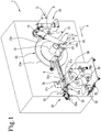
Figure 1 is a perspective view of the crimping unit according to this invention; -
Figure 2 is a detail view showing a part of the gathering station; -
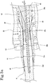
Figure 3 is a cross-section of the part shown inFigure 2 ; -
Figure 3a shows a detail fromFigure 3 ; -
Figure 4 is a perspective view of some components of the gathering unit. - With reference to the accompanying drawings, the numeral 1 denotes a crimping unit in its entirety, hereinafter referred to simply as unit 1.
- The unit 1 comprises a
feed station 10 configured to feed to the crimping unit 1 aweb 100 of material of the tobacco industry, acrimping station 20 equipped withcrimping rollers gathering station 30 located downstream of thecrimping station 20. - The unit 1 comprises feed means 11 for feeding the
web 100 of material for the tobacco industry, for example of tobacco based material, filter paper or PLA. - The
web 100 is adapted to be unwound along a longitudinal feed direction, indicated by the arrow "A" inFigure 1 . - Together with the feed means 11, the machine 1 preferably also comprises one or more systems for adjusting the tension of the web 100 (for example, an unwinding feedback sensor) and/or one or more systems for centring the
web 100. - To ensure the
web 100 is correctly transferred to the further processing stations of the unit 1, the feed means 11, too, are equipped withtensioning devices 12 for tensioning theweb 100, embodied for example by dancer rollers. - The
feed station 10 comprises at least one infeeddiverting roller 13 mounted on a movable supportingdevice 13a. - The movable supporting
device 13a is configured to move the infeeddiverting roller 13 along a predetermined path "B" in such a way as to vary the infeed position of the web in thecrimping station 20, specifically varying the orientation of the web being fed to thecrimping rollers - The path "B" is preferably straight and the movable supporting
device 13a comprises a carriage which mounts thediverting roller 13 and which is movable along a respective straight guide, for example disposed vertically in such a way as to define a substantially vertical path "B". - The presence of the at least one
diverting roller 13 thus makes it possible, also in use, to modulate the angular portion of thecrimping rollers web 100, in particular when entering thecrimping station 20, thus helping to lengthen/shorten the stretch of path which theweb 100 travels in contact with the surface of thecrimping rollers - The
crimping station 20 comprises afirst crimping roller 21 and asecond crimping roller 22 operatively coupled to make a plurality of longitudinal easy folding lines on theweb 100 in transit between the twocrimping rollers - The
crimping rollers crimping rollers - Advantageously, the crimping station comprises a supporting
element 23 for supporting thecrimping rollers web 100 in thecrimping station 20; the supportingelement 23 thus comprises motor means 23b acting on the supportingelement 23 to vary the position and/or orientation of the supportingelement 23. - In other words, the supporting element is movable in such a way as to be able to modify the arrangement of the
crimping rollers web 100 follow a different path defined by the specific arrangement adopted by thecrimping rollers - In a preferred embodiment, the supporting
element 23 is rotatable about an axis of adjustment "X" to allow turning thecrimping station 20 in such a way as to modify, by increasing or decreasing, the winding angle of theweb 100 on the first and/or thesecond crimping roller - Preferably, the supporting
element 23 is embodied by avertical plate 23a which is supported rotatably about the axis of adjustment "X". - Also in this preferred embodiment, the
first crimping roller 21 is supported by the supportingelement 23 and is connected thereto at its centre of rotation, while thesecond crimping roller 22 is supported by the supportingelement 23 and connected thereto in a zone outside its centre of rotation. - In other words, the axis of rotation of the
first crimping roller 21 is coaxial with the axis of adjustment "X", while the axis of rotation "Y" of thesecond crimping roller 22 is eccentric relative to the axis of adjustment "X". - Thus, during rotation of the supporting
element 23, the position of thefirst crimping roller 21 remains substantially unchanged, while thesecond crimping roller 22 performs a movement of revolution around thefirst crimping roller 21. - The supporting
element 23 is rotatably supported at a peripheral portion by means of a curved guide which extends around at least one stretch of a circle concentric with the axis of adjustment "X". - The curved guide can define a closed path or, alternatively, an open stretch, depending on the range of angular adjustment around the axis of adjustment "X".
- The supporting
element 23 also comprises guide means, such as, for example, roller pairs, sliders or other, which are slidably engaged on the curved guide. - The supporting
element 23 also comprises motor means, preferably embodied by a rack and pinion drive mechanism disposed in proximity to the curved guide and associated therewith in such a way as to allow it to perform a movement, specifically a rotation, about the axis of adjustment "X". - Preferably, the
second crimping roller 22 is adjustably mounted on the supportingelement 23 in such a way as to allow varying its position relative to thefirst crimping roller 21. - This technical feature allows moving the
second crimping roller 22 towards/away from thefirst crimping roller 21 in such a way as, for example, to allow inserting theweb 100, facilitate maintenance and repairs on thecrimping station 20 or allow adapting the distance between thecrimping rollers web 100 to be crimped. - More specifically, the second crimping
roller 22 is mounted on the supportingelement 23 by means of an eccentric,rotatable roller bracket 22a. - The
roller bracket 22a is configured to rotate about a respective axis of rotation "Y" parallel to the axis of adjustment "X" and thesecond crimping roller 22 is mounted on theroller bracket 22a rotatably about a respective axis of rotation "Z" parallel and eccentric relative to the axis of rotation "Y" of theroller bracket 22a. - That way, the rotation of the
roller bracket 22a about its axis of rotation "Y" causes displacement of the axis of rotation "Z" of thesecond crimping roller 22 and hence, displacement of thecrimping rollers - The
roller bracket 22a is associated with an actuator configured to rotate theroller bracket 22a by a fine adjustment movement about the respective axis of rotation "Y". - In other words, the supporting
element 23 comprises an actuator which allows rotating theroller bracket 22a in such a way as to cause the second crimpingroller 22 mounted thereon to rotate eccentrically, thereby moving it towards/away from thefirst crimping roller 21. - In order to optimize adjustment of the rotational movement of the
roller bracket 22a, the supportingelement 23 comprises a limit stop device which defines a limit to the rotational movement of the roller bracket. - The limit stop device may be embodied, for example, by an adjustment screw or a rotary lead nut and screw coupling, so as to allow the angular stroke of the
roller bracket 22a to be adjusted very precisely. - Preferably upstream of the
crimping rollers web 100, thecrimping station 20 also comprises aguide roller 24 mounted on the supportingelement 23 eccentrically relative to the axis of adjustment "X". - More specifically, the
guide roller 24 is associated with the supportingelement 23 in such a way as to intercept and divert the stretch of theweb 100 between the exit of theinfeed station 10, specifically from thediverting roller 13, and thecrimping rollers element 23 is in a first position interval, and so as not to intercept theweb 100 when the supportingelement 23 is in a second position interval, different from the first interval, thus moving to a non-operating position. - In particular, in the preferred embodiment where the supporting
element 23 is a plate rotatable about the axis of adjustment "X", the first position interval is a first interval of angular positions, while the second position interval is a second interval of angular positions. - In other words, the supporting
element 23 is configured to rotate between a plurality of possible positions where the guide roller 24 intercepts or does not intercept theweb 100. - In use, therefore, as it passes from the
feed station 10 to thecrimping station 20 and before it engages thecrimping rollers guide roller 24. - When the
web 100 engages theguide roller 24, the latter provides a reference point which determines the point of engagement of theweb 100 with thecrimping rollers diverting roller 13, if any, of thefeed station 10, and thus allowing stably fixing the geometry of the path followed by theweb 100 entering thecrimping station 20 and at the same time keeping the possibility of modifying the path at the exit by moving the supportingelement 23. - Advantageously, the
guide roller 24 is selectively engageable in such a way as to allow fixing or not fixing the geometry of the path followed by theweb 100 entering thecrimping station 20 depending on whether or not it is necessary to modulate only the path of theweb 100 at the exit of thecrimping station 20. - Preferably, the
guide roller 24 is rotationally at a fixed position on the supportingelement 23. - The crimping unit 1 also comprises a
gathering station 30 configured to receive theweb 100 and progressively gather it in order to give the web a substantially cylindrical shape. - More specifically, along the feed direction "A" of the
web 100, thegathering station 30 comprises apre-shaping member 31 whose cross-sectional shape transverse to the feed direction "A" is curved and shaped to give the web 100 a shape substantially like that of a U. - In other words, the shape of the
pre-shaping member 31 is such as to allow theweb 100 from the crimpingstation 20 to be deformed by simultaneously closing the web on itself to obtain an at least partly cylindrical shape of theweb 100, preferably according to the above mentioned substantially U shaped form, and folding the web on at least some of the longitudinal fold lines. - The
gathering station 30 also comprises ashaping device 32 configured to receive thepre-shaped web 100 from thepre-shaping member 31. - The shaping device has a shaping
duct 32a, described in more detail below, whose function is to reduce theweb 100 by forcing it to pass through a tubular duct in such a way as to give theweb 100 the substantially cylindrical shape. - More specifically, the
outside surface 31a has a general shape which, in transverse cross-section, is at least partly annular or tubular, to give the web 100 a substantially cylindrical shape, and, along it, theoutside surface 31a is provided with a succession of protrusions and recesses adapted to engage theweb 100 at respective longitudinal easy folding lines in such a way as to pre-fold theweb 100 simultaneously along the longitudinal easy folding lines. - Preferably, the protrusions and recesses are distributed along the entire
outside surface 31a of thepre-shaping member 31. - Still more preferably, the protrusions and recesses are distributed non-uniformly along the
outside surface 31a of thepre-shaping member 31. - More specifically, the spacing between adjacent protrusions for engaging a portion of the edge of the
web 100 is greater than the spacing between adjacent protrusions intended to engage a central portion of theweb 100. - This structure allows obtaining a particularly functional distribution of the pressure on the
web 100, transferring the latter in optimum manner to theshaping device 32 in such a way as to improve the structural quality of the continuous stream resulting from the step of gathering theweb 100. - The
outside surface 31a of thepre-shaping member 31 extends along an open line joined by a supportingportion 31b configured to keep thepre-shaping member 31 suspended at a predetermined position. - In other words, the
pre-shaping member 31 comprises a supportingportion 31b which supports and connects it to the body of the crimping unit 1 in such way that it can, in use, remain in the correct position to engage theweb 100. - The crimping unit also comprises adjustment means 31c, associated with the supporting
portion 31b, for adjusting the position and/or orientation of thepre-shaping member 31. - The presence of the adjustment means 31c allows moving the
pre-shaping member 31 to dynamically modify its position and/or orientation, in particular relative to theweb 100. - This movement is accomplished preferably by a translation in a direction perpendicular to the feed direction of the
web 100 around thepre-shaping member 32 and may adopt a vertical orientation when theweb 100 passes horizontally over thepre-shaping member 32. - This movement may also be accomplished by a rotation about an axis of rotation "K" transverse to the feed direction of the
web 100 and preferably horizontal. This rotation can therefore be added to the aforementioned translational movement and is preferably controllable independently thereof. - That way, it is possible to vary both the force applied by the
pre-shaping member 31 on theweb 100 and the extent of the outside surface of it 31a which comes into contact with the web. - In a preferred embodiment shown in the accompanying drawings, the
pre-shaping device 31 is configured to be positioned above theweb 100 and to tension it by applying a downwardly directed force. - In other words, the
outside surface 31a of thepre-shaping member 31 has an upward facing concavity and the adjustment means 31c are configured to lower thepre-shaping member 31 to engage theweb 100 by pushing it downwards or to lift thepre-shaping member 31 to reduce the force it applies on theweb 100 until it is disengaged from the web. - It is stressed, therefore, that the adjustment means 31c might also be configured to perform only the rotational movement about the axis "K" without necessarily being structured to perform the translational movement, and vice versa.
- The
gathering station 30 also comprises a shapingduct 32a and an insertingdevice 33 configured to insert an additional component "C" into the stream formed by the gatheredweb 100. - More specifically, the inserting
device 33 comprises an insertingduct 34 for inserting the additional component "C" placed inside the shapingduct 32a, preferably coaxially therewith. - That way, the additional component "C" is positioned centrally in the rod formed by gathering the
web 100. - Advantageously, the shaping
duct 32a is convergent in shape along the feed direction of the additional component "C" which substantially coincides with the feed direction "A" of theweb 100, at least in the stretch of path through thegathering station 30. - In a preferred embodiment, the shaping
duct 32a has a frustoconical profile. - More specifically, as illustrated in
Figures 3 and3a , the shapingduct 32a comprises atubular element 37 with a longitudinal axis "L" and has anoutside wall 38 and aninside wall 39. - The
tubular element 37 has aninlet opening 40, where thepre-shaped web 100 enters, and anoutlet opening 41 through which theweb 100 exits with a substantially cylindrical shape. - The
tubular element 37 comprises a plurality of sections disposed in sequence along its longitudinal axis L. - More precisely, the sections are disposed one after the other and are connected to each other. The sections of the
tubular element 37 are connected to one another and their respective transverse tubular inside dimensions vary along the longitudinal axis "L". - In other words, the transverse dimensions of the respective inside walls of the aforesaid sections can increase, decrease or remain constant along their extension along the longitudinal axis L.
- Taking as references the longitudinal axis "L" and the feed direction of the
web 100, indicated by the arrow F, which, inFigures 3 and3a , is directed from right to left, the tubular element comprises aninlet section 42, a firstintermediate section 43, a secondintermediate section 44 and anoutlet section 45. The different sections are disposed one after the other and are connected to each other. - More specifically, at the
inlet section 42, theinside wall 39 has aportion 39a which has a frustoconical shape, convergent towards the longitudinal axis L. At the firstintermediate section 43, theinside wall 39 has aportion 39b which is frustoconical in shape, divergent towards the feed direction F and which, at its outlet end, connects with the secondintermediate section 44 which has aninside wall portion 39c that is substantially ring-shaped, with a constant diameter along its entire length. - Lastly, the
inside wall portion 39d of theoutlet section 45 is frustoconical in shape, convergent towards theoutlet opening 41. - It should be noted that during the shaping process, specifically during the passage of the
web 100 through thetubular element 37 of the shapingduct 32a, strong friction is created between theinside wall 39 and the fibres of theweb 100 sliding against it. - As a result, both the
tubular element 37 and theweb 100, especially the outermost fibres thereof, are heated. - To prevent heating resulting in poor quality end products, the gathering station, specifically the shaping
duct 32a, comprises pneumatic conveying means associated with the shapingduct 32a to convey and cool the web ofmaterial 100 as it traverses the shapingduct 32a through flows of a pressurized fluid which act on the shapingduct 32a in between theweb 100 and the inside surface of the shapingduct 32a itself. - The pneumatic, conveying and cooling means are defined by flows of a pressurized fluid acting on the shaping
duct 32a. - The pneumatic, conveying and cooling means constitute lubricating means distributed along the
inside wall 39 of thetubular element 37 and capable of flowing between the two surfaces which come into contact with each other as theweb 100 moves forward through the shapingduct 32a. - More specifically, the surface of the
web 100 slides against the inside wall of thetubular element 37. - More specifically, the pneumatic, conveying and cooling means comprise a plurality of
ducts 46 extending from an annular chamber, converging axially towards the longitudinal axis "L" of thetubular element 37 and leading intorespective openings 46a made in thetubular element 37 - Preferably, the
ducts 46 of the plurality ofducts 46 are angularly distributed round the longitudinal axis L. - In the embodiment illustrated in
Figures 3 and3a , theopenings 46a are made at the inlet end of the first intermediate section. - The
openings 46a are connected at their inlet ends to a source of pressurized fluid and lead into thetubular element 37. - The pressurized fluid, usually air, reaches the
openings 46a by way of a chamber defined by atubular liner 48. More specifically, the liner is not provided at the outlet end of theelement 37. - The outlets of the
openings 46a preferably have the shape of an isosceles triangle with the vertex directed towards theaforementioned outlet opening 41. They are angularly distributed over the entire surface of revolution of theinside wall 39 at the inlet end of the first intermediate section. - The pressurized fluid, or rather, the multiple flows of fluid, emitted by the
openings 46a, is distributed in a substantially uniform manner over the entire inside surface of thewall 39, following a feed direction towards the outlet opening 41 of thetubular element 37. - The flows of fluid form an uninterrupted layer of pressurized fluid which is distributed over the entire surface of the
inside wall 39 and which creates a layer of pneumatic "lubricant" between the web ofmaterial 100 and thewall 39. The web ofmaterial 100 moving towards theoutlet opening 41 tends to not stick to theinside wall 39 and is thus prevented from rubbing against the latter. - The pressurized fluid, besides creating the layer of "lubricant", also constitutes a coolant which cools the
tubular element 37. - In effect, the flow of cold fluid along the chamber defined by the
tubular liner 48 also has the effect of cooling thetubular element 37. - Obviously, cooling the
tubular element 37 means that itsinside wall 39 is cooled which in turn cools theweb 100 that is being progressively reduced. - Returning now to the additional component "C", this is preferably a flavouring component which allows giving the web 100 a specific aroma to modify the flavour of the smoke produced by the end product made using the
web 100. More specifically, the flavouring component may comprise a thread made of or impregnated with a flavouring material. To ensure the flavouring thread is correctly transferred into theweb 100, the insertingdevice 33 comprises tensioningmembers 33a adapted to keep the flavouring thread under tension. - The inserting device may further comprises a
roll holder 35 configured to support a plurality of rolls of additional component "C" and to adopt variable positions and/or orientations in such a way as to change the position of the rolls. - The presence of the
roll holder 35 optimizes the production process of the rod from theweb 100 comprising the additional component "C" because it allows automating the switch from one roll to another in such a way as to allow replacing depleted rolls with new rolls without interrupting the production process of the crimping unit 1. - In other words, this ensures that there is at least one roll of additional material "C" present at all times for use in the production of the end product. More specifically, the
roll holder 35 comprises a plurality ofsupports 36 associable with respective rolls of additional material "C" and rotatable to move the respective rolls towards or away from the formingduct 32a. - The
roll holder 35 is thus configured to move asingle support 36 containing a roll of additional material "C" to the formingduct 32a and, when the roll is nearly depleted, to move it away from the formingduct 32a and to automatically replace it with a new roll on anothersupport 36. - Advantageously, the
openings 46a and the flows of pressurized fluid constitute an effective means of cooling the shaping duct and effective lubricating means interposed between the web and the inside wall of thetubular element 37. Also advantageously, the inserting device provides a particularly efficient and functional solution for precisely and effectively inserting an additional component "C" inside the rod obtainable from theweb 100. - In the light of the above, this invention achieves the preset aims and overcomes the abovementioned disadvantages of the prior art by providing a crimping unit which allows optimizing the process of crimping the
web 100 and making a continuous rod from that web of material for the tobacco industry.
Claims (13)
- A crimping unit for crimping a web of material (100) used to make tobacco industry products, comprising:- a crimping station (20) having a first crimping roller (21) and a second crimping roller (22) operatively coupled to make a plurality of longitudinal easy folding lines on the web of material (100) in transit between the crimping rollers (21, 22);- a gathering station (30), located downstream of the crimping station (20) and comprising a shaping duct (32a) configured to receive the web of material (100) and progressively gather it in order to give the web of material (100) a substantially cylindrical shape.the crimping unit being characterized in that it comprises pneumatic, conveying and cooling means associated with the shaping duct (32a) to convey and cool the web of material (100) as it traverses the shaping duct (32a) through flows of a pressurized fluid which act on the shaping duct (32a) in between the web (100) and the inside surface of the shaping duct (32a) itself.
- The crimping unit according to claim 1, wherein the pneumatic, conveying and cooling means are defined by flows of a pressurized fluid acting on the shaping duct (32a) and capable of flowing between the two surfaces which come into contact with each other as the web (100) moves forward through the shaping duct (32a) itself.
- The crimping unit according to claim 1 or 2, wherein the pneumatic, conveying and cooling means comprise a plurality of ducts (46) extending from an annular chamber, converging axially towards a longitudinal axis (L) of the tubular element (37) and leading into respective openings (46a) made in the tubular element (37).
- The crimping unit according to claim 3, wherein the ducts (46) of the plurality of ducts (46) are angularly distributed round the longitudinal axis (L).
- The crimping unit according to one or more of the preceding claims, wherein the tubular element (37) comprises a chamber defined by a tubular liner (48) at least partly surrounding the outer wall (39) of the tubular element (37), the pneumatic, conveying and cooling means comprising a pressurized fluid capable of passing through the chamber and cooling the tubular element (37) itself.
- The crimping unit according to one or more of the preceding claims, wherein the gathering station (30) comprises an inserting device (33) configured to insert an additional component (C) into the stream formed by the gathered web (100).
- The crimping unit according to one or more of the preceding claims, wherein the inserting device (33) comprises an inserting duct (34) for inserting the additional component (C) placed inside the shaping duct (32a), preferably coaxially therewith.
- The unit according to claim 6, wherein the shaping duct (32a) is convergent in shape along the feed direction of the additional component (C), the shaping duct (32a) preferably having a frustoconical profile.
- The unit according to one or more of claims 6 to 8, wherein the additional component (C) is a flavouring component.
- The unit according to claim 9, wherein the flavouring component comprises a thread made of or impregnated with a flavouring material.
- The unit according to claim 10, wherein the inserting device (33) comprises tensioning members (33a) adapted to keep the flavouring thread under tension.
- The unit according to one or more of claims 6 to 11, wherein the inserting device (33) comprises a roll holder (35) configured to support a plurality of rolls of additional component (C) and to adopt a variable positions and/or orientations in such a way as to change the position of the rolls.
- The unit according to claim 12, wherein the roll holder (35) comprises a plurality of supports (36) associable with respective rolls and rotatable to move the respective rolls towards or away from the transfer duct (34).
Applications Claiming Priority (1)
| Application Number | Priority Date | Filing Date | Title |
|---|---|---|---|
| IT102017000117804A IT201700117804A1 (en) | 2017-10-18 | 2017-10-18 | Crimping unit |
Publications (2)
| Publication Number | Publication Date |
|---|---|
| EP3473111A1 true EP3473111A1 (en) | 2019-04-24 |
| EP3473111B1 EP3473111B1 (en) | 2022-12-07 |
Family
ID=61224370
Family Applications (1)
| Application Number | Title | Priority Date | Filing Date |
|---|---|---|---|
| EP18200609.8A Active EP3473111B1 (en) | 2017-10-18 | 2018-10-16 | Crimping unit |
Country Status (3)
| Country | Link |
|---|---|
| EP (1) | EP3473111B1 (en) |
| IT (1) | IT201700117804A1 (en) |
| PL (1) | PL3473111T3 (en) |
Cited By (2)
| Publication number | Priority date | Publication date | Assignee | Title |
|---|---|---|---|---|
| CN115279214A (en) * | 2019-10-09 | 2022-11-01 | 菲利普莫里斯生产公司 | Method and apparatus for forming a strip of continuous web material |
| WO2023082001A1 (en) * | 2021-11-12 | 2023-05-19 | Hexo Operations Inc. | Machinery for forming smoking articles of cannabis compositions |
Citations (9)
| Publication number | Priority date | Publication date | Assignee | Title |
|---|---|---|---|---|
| US3383449A (en) * | 1964-10-01 | 1968-05-14 | Muller Paul Adolf | Method for producing an endless filter string |
| GB1314511A (en) * | 1969-04-10 | 1973-04-26 | Molins Machine Co Ltd | Continuous rod making machines and heat exchangers for use in them |
| EP0088178A2 (en) * | 1982-03-10 | 1983-09-14 | Celanese Corporation | Method and apparatus for forming cigarette filter rods |
| US4807809A (en) | 1988-02-12 | 1989-02-28 | R. J. Reynolds Tobacco Company | Rod making apparatus for smoking article manufacture |
| EP0482283B1 (en) | 1990-10-24 | 1995-06-07 | SANJO MACHINE WORKS, Ltd. | Cigarette filter rod, method and apparatus for producing the same |
| US5469871A (en) | 1992-09-17 | 1995-11-28 | R. J. Reynolds Tobacco Company | Cigarette and method of making same |
| WO2015097127A1 (en) | 2013-12-23 | 2015-07-02 | Philip Morris Products S.A. | Method and apparatus for treating continuous sheet material |
| WO2016071267A1 (en) | 2014-11-03 | 2016-05-12 | Philip Morris Products S.A. | Method and apparatus for manufacturing a crimped web |
| WO2016097100A1 (en) * | 2014-12-18 | 2016-06-23 | Philip Morris Products S.A. | Apparatus and method for making filters |
Family Cites Families (12)
| Publication number | Priority date | Publication date | Assignee | Title |
|---|---|---|---|---|
| CH331197A (en) | 1955-04-05 | 1958-07-15 | Mueller Paul Adolf Dipl Ing | Mechanical device for the production of an endless filter rod for cigarettes |
| CH625403A5 (en) | 1977-08-11 | 1981-09-30 | Celfil Co | |
| GB2020158B (en) | 1978-04-21 | 1982-11-24 | Cigarette Components Ltd | Production of tobacco smoke filters |
| US5163452A (en) | 1990-09-20 | 1992-11-17 | R. J. Reynolds Tobacco Company | Rod making apparatus for use in the manufacture of smoking articles |
| JPH067143A (en) | 1992-06-24 | 1994-01-18 | Japan Tobacco Inc | Filter-carrying device of cigarette filter-producing machine |
| US5331976A (en) | 1992-10-21 | 1994-07-26 | Hoechst Celanese Corporation | Transport jet adapter |
| EP1978834B1 (en) | 2006-01-27 | 2010-04-21 | British American Tobacco (Investments) Limited | Method of preparing a rod for use in the preparation of a smoking article |
| US7740019B2 (en) | 2006-08-02 | 2010-06-22 | R.J. Reynolds Tobacco Company, Inc. | Equipment and associated method for insertion of material into cigarette filters |
| ITBO20060749A1 (en) | 2006-10-31 | 2007-01-30 | Gd Spa | FILTER PACKAGING MACHINE FOR SMOKE ITEMS |
| GB0905211D0 (en) | 2009-03-26 | 2009-05-13 | British American Tobacco Co | Guide nozzle for use with filter rod manufacturing apparatus |
| ITBO20110743A1 (en) | 2011-12-22 | 2012-03-22 | Gd Spa | POWER SUPPLY UNIT OF A WIRE TO AN AUTOMATIC PACKAGING MACHINE. |
| RU2696400C2 (en) | 2014-12-16 | 2019-08-01 | Филип Моррис Продактс С.А. | Method and apparatus for molding substantially flat continuous material |
-
2017
- 2017-10-18 IT IT102017000117804A patent/IT201700117804A1/en unknown
-
2018
- 2018-10-16 EP EP18200609.8A patent/EP3473111B1/en active Active
- 2018-10-16 PL PL18200609.8T patent/PL3473111T3/en unknown
Patent Citations (10)
| Publication number | Priority date | Publication date | Assignee | Title |
|---|---|---|---|---|
| US3383449A (en) * | 1964-10-01 | 1968-05-14 | Muller Paul Adolf | Method for producing an endless filter string |
| GB1314511A (en) * | 1969-04-10 | 1973-04-26 | Molins Machine Co Ltd | Continuous rod making machines and heat exchangers for use in them |
| EP0088178A2 (en) * | 1982-03-10 | 1983-09-14 | Celanese Corporation | Method and apparatus for forming cigarette filter rods |
| US4807809A (en) | 1988-02-12 | 1989-02-28 | R. J. Reynolds Tobacco Company | Rod making apparatus for smoking article manufacture |
| EP0482283B1 (en) | 1990-10-24 | 1995-06-07 | SANJO MACHINE WORKS, Ltd. | Cigarette filter rod, method and apparatus for producing the same |
| DE69110240T2 (en) | 1990-10-24 | 1995-12-21 | Sanyo Machine Works | Cigarette filter train, method and device for producing the same. |
| US5469871A (en) | 1992-09-17 | 1995-11-28 | R. J. Reynolds Tobacco Company | Cigarette and method of making same |
| WO2015097127A1 (en) | 2013-12-23 | 2015-07-02 | Philip Morris Products S.A. | Method and apparatus for treating continuous sheet material |
| WO2016071267A1 (en) | 2014-11-03 | 2016-05-12 | Philip Morris Products S.A. | Method and apparatus for manufacturing a crimped web |
| WO2016097100A1 (en) * | 2014-12-18 | 2016-06-23 | Philip Morris Products S.A. | Apparatus and method for making filters |
Cited By (3)
| Publication number | Priority date | Publication date | Assignee | Title |
|---|---|---|---|---|
| CN115279214A (en) * | 2019-10-09 | 2022-11-01 | 菲利普莫里斯生产公司 | Method and apparatus for forming a strip of continuous web material |
| CN115279214B (en) * | 2019-10-09 | 2023-09-15 | 菲利普莫里斯生产公司 | Method and apparatus for forming continuous web material into strips |
| WO2023082001A1 (en) * | 2021-11-12 | 2023-05-19 | Hexo Operations Inc. | Machinery for forming smoking articles of cannabis compositions |
Also Published As
| Publication number | Publication date |
|---|---|
| EP3473111B1 (en) | 2022-12-07 |
| PL3473111T3 (en) | 2023-03-27 |
| IT201700117804A1 (en) | 2019-04-18 |
Similar Documents
| Publication | Publication Date | Title |
|---|---|---|
| US11166488B2 (en) | Method and apparatus for shaping substantially flat continuous material | |
| EP3473111B1 (en) | Crimping unit | |
| KR20200102450A (en) | Methods and units for crimping webs of materials for the tobacco industry | |
| US8262966B2 (en) | Process for cooling flat plastic products | |
| EP3473113B1 (en) | Crimping unit | |
| CN106457657A (en) | Adjustable-angle pressing or nip roll | |
| US10647076B2 (en) | Stretching device for an apex filler strip for tire beads and apex handling system comprising the stretching device | |
| WO2015097127A1 (en) | Method and apparatus for treating continuous sheet material | |
| JP2009112276A (en) | Rod-forming machine | |
| EP2862615B1 (en) | A hot melt glue dispenser device | |
| CN111629613A (en) | Method and apparatus for folding a web of material | |
| EP3473112B1 (en) | Crimping unit | |
| EP3383617B1 (en) | Calendering facility for reinforcement plies for tyres | |
| CN111491901B (en) | Method of making a glass ribbon | |
| EP3413728B1 (en) | Apparatus and method for making semifinished products intended to form part of smokers' articles | |
| CN108284584B (en) | Polyester insulating tube processing device and processing technology | |
| CN104872818B (en) | Method and device for producing a rod for the tobacco processing industry | |
| CN105876849B (en) | Apparatus for manufacturing articles of the tobacco processing industry | |
| US20230068917A1 (en) | Production machine for producing rod-shaped products from an end-less strand of a strip adhesively bonded to form a tube | |
| CA2891690A1 (en) | A method and apparatus for spirally winding a thermoplastic profile in the manufacture of welded plastic tubes | |
| US20220324157A1 (en) | Method and device for producing helical coils | |
| EP3756855B1 (en) | Production line and relative method of production for obtaining a longitudinally and transversally stretched ptfe strip | |
| CN112055624A (en) | Coil winding method and system for hot rolled products | |
| EP2604132B1 (en) | Compacting assembly, with a thread insertion unit, for an automatic cigarette filter manufacturing machine | |
| CN116463811A (en) | Preshrinking machine for knitting elastic cloth dyeing process and dyeing process |
Legal Events
| Date | Code | Title | Description |
|---|---|---|---|
| PUAI | Public reference made under article 153(3) epc to a published international application that has entered the european phase |
Free format text: ORIGINAL CODE: 0009012 |
|
| STAA | Information on the status of an ep patent application or granted ep patent |
Free format text: STATUS: THE APPLICATION HAS BEEN PUBLISHED |
|
| AK | Designated contracting states |
Kind code of ref document: A1 Designated state(s): AL AT BE BG CH CY CZ DE DK EE ES FI FR GB GR HR HU IE IS IT LI LT LU LV MC MK MT NL NO PL PT RO RS SE SI SK SM TR |
|
| AX | Request for extension of the european patent |
Extension state: BA ME |
|
| STAA | Information on the status of an ep patent application or granted ep patent |
Free format text: STATUS: REQUEST FOR EXAMINATION WAS MADE |
|
| 17P | Request for examination filed |
Effective date: 20190808 |
|
| RBV | Designated contracting states (corrected) |
Designated state(s): AL AT BE BG CH CY CZ DE DK EE ES FI FR GB GR HR HU IE IS IT LI LT LU LV MC MK MT NL NO PL PT RO RS SE SI SK SM TR |
|
| STAA | Information on the status of an ep patent application or granted ep patent |
Free format text: STATUS: EXAMINATION IS IN PROGRESS |
|
| 17Q | First examination report despatched |
Effective date: 20201201 |
|
| STAA | Information on the status of an ep patent application or granted ep patent |
Free format text: STATUS: EXAMINATION IS IN PROGRESS |
|
| GRAP | Despatch of communication of intention to grant a patent |
Free format text: ORIGINAL CODE: EPIDOSNIGR1 |
|
| STAA | Information on the status of an ep patent application or granted ep patent |
Free format text: STATUS: GRANT OF PATENT IS INTENDED |
|
| RIC1 | Information provided on ipc code assigned before grant |
Ipc: A24C 5/01 20200101ALI20220531BHEP Ipc: A24D 3/02 20060101ALI20220531BHEP Ipc: A24B 3/14 20060101AFI20220531BHEP |
|
| TPAC | Observations filed by third parties |
Free format text: ORIGINAL CODE: EPIDOSNTIPA |
|
| INTG | Intention to grant announced |
Effective date: 20220622 |
|
| INTG | Intention to grant announced |
Effective date: 20220922 |
|
| GRAS | Grant fee paid |
Free format text: ORIGINAL CODE: EPIDOSNIGR3 |
|
| GRAA | (expected) grant |
Free format text: ORIGINAL CODE: 0009210 |
|
| STAA | Information on the status of an ep patent application or granted ep patent |
Free format text: STATUS: THE PATENT HAS BEEN GRANTED |
|
| AK | Designated contracting states |
Kind code of ref document: B1 Designated state(s): AL AT BE BG CH CY CZ DE DK EE ES FI FR GB GR HR HU IE IS IT LI LT LU LV MC MK MT NL NO PL PT RO RS SE SI SK SM TR |
|
| REG | Reference to a national code |
Ref country code: GB Ref legal event code: FG4D |
|
| REG | Reference to a national code |
Ref country code: CH Ref legal event code: EP Ref country code: AT Ref legal event code: REF Ref document number: 1535749 Country of ref document: AT Kind code of ref document: T Effective date: 20221215 |
|
| REG | Reference to a national code |
Ref country code: DE Ref legal event code: R096 Ref document number: 602018043916 Country of ref document: DE |
|
| REG | Reference to a national code |
Ref country code: IE Ref legal event code: FG4D |
|
| REG | Reference to a national code |
Ref country code: NL Ref legal event code: FP |
|
| REG | Reference to a national code |
Ref country code: LT Ref legal event code: MG9D |
|
| PG25 | Lapsed in a contracting state [announced via postgrant information from national office to epo] |
Ref country code: SE Free format text: LAPSE BECAUSE OF FAILURE TO SUBMIT A TRANSLATION OF THE DESCRIPTION OR TO PAY THE FEE WITHIN THE PRESCRIBED TIME-LIMIT Effective date: 20221207 Ref country code: NO Free format text: LAPSE BECAUSE OF FAILURE TO SUBMIT A TRANSLATION OF THE DESCRIPTION OR TO PAY THE FEE WITHIN THE PRESCRIBED TIME-LIMIT Effective date: 20230307 Ref country code: LT Free format text: LAPSE BECAUSE OF FAILURE TO SUBMIT A TRANSLATION OF THE DESCRIPTION OR TO PAY THE FEE WITHIN THE PRESCRIBED TIME-LIMIT Effective date: 20221207 Ref country code: FI Free format text: LAPSE BECAUSE OF FAILURE TO SUBMIT A TRANSLATION OF THE DESCRIPTION OR TO PAY THE FEE WITHIN THE PRESCRIBED TIME-LIMIT Effective date: 20221207 Ref country code: ES Free format text: LAPSE BECAUSE OF FAILURE TO SUBMIT A TRANSLATION OF THE DESCRIPTION OR TO PAY THE FEE WITHIN THE PRESCRIBED TIME-LIMIT Effective date: 20221207 |
|
| REG | Reference to a national code |
Ref country code: AT Ref legal event code: MK05 Ref document number: 1535749 Country of ref document: AT Kind code of ref document: T Effective date: 20221207 |
|
| PG25 | Lapsed in a contracting state [announced via postgrant information from national office to epo] |
Ref country code: RS Free format text: LAPSE BECAUSE OF FAILURE TO SUBMIT A TRANSLATION OF THE DESCRIPTION OR TO PAY THE FEE WITHIN THE PRESCRIBED TIME-LIMIT Effective date: 20221207 Ref country code: LV Free format text: LAPSE BECAUSE OF FAILURE TO SUBMIT A TRANSLATION OF THE DESCRIPTION OR TO PAY THE FEE WITHIN THE PRESCRIBED TIME-LIMIT Effective date: 20221207 Ref country code: HR Free format text: LAPSE BECAUSE OF FAILURE TO SUBMIT A TRANSLATION OF THE DESCRIPTION OR TO PAY THE FEE WITHIN THE PRESCRIBED TIME-LIMIT Effective date: 20221207 Ref country code: GR Free format text: LAPSE BECAUSE OF FAILURE TO SUBMIT A TRANSLATION OF THE DESCRIPTION OR TO PAY THE FEE WITHIN THE PRESCRIBED TIME-LIMIT Effective date: 20230308 |
|
| P01 | Opt-out of the competence of the unified patent court (upc) registered |
Effective date: 20230527 |
|
| PG25 | Lapsed in a contracting state [announced via postgrant information from national office to epo] |
Ref country code: SM Free format text: LAPSE BECAUSE OF FAILURE TO SUBMIT A TRANSLATION OF THE DESCRIPTION OR TO PAY THE FEE WITHIN THE PRESCRIBED TIME-LIMIT Effective date: 20221207 Ref country code: RO Free format text: LAPSE BECAUSE OF FAILURE TO SUBMIT A TRANSLATION OF THE DESCRIPTION OR TO PAY THE FEE WITHIN THE PRESCRIBED TIME-LIMIT Effective date: 20221207 Ref country code: PT Free format text: LAPSE BECAUSE OF FAILURE TO SUBMIT A TRANSLATION OF THE DESCRIPTION OR TO PAY THE FEE WITHIN THE PRESCRIBED TIME-LIMIT Effective date: 20230410 Ref country code: EE Free format text: LAPSE BECAUSE OF FAILURE TO SUBMIT A TRANSLATION OF THE DESCRIPTION OR TO PAY THE FEE WITHIN THE PRESCRIBED TIME-LIMIT Effective date: 20221207 Ref country code: CZ Free format text: LAPSE BECAUSE OF FAILURE TO SUBMIT A TRANSLATION OF THE DESCRIPTION OR TO PAY THE FEE WITHIN THE PRESCRIBED TIME-LIMIT Effective date: 20221207 Ref country code: AT Free format text: LAPSE BECAUSE OF FAILURE TO SUBMIT A TRANSLATION OF THE DESCRIPTION OR TO PAY THE FEE WITHIN THE PRESCRIBED TIME-LIMIT Effective date: 20221207 |
|
| PG25 | Lapsed in a contracting state [announced via postgrant information from national office to epo] |
Ref country code: SK Free format text: LAPSE BECAUSE OF FAILURE TO SUBMIT A TRANSLATION OF THE DESCRIPTION OR TO PAY THE FEE WITHIN THE PRESCRIBED TIME-LIMIT Effective date: 20221207 Ref country code: IS Free format text: LAPSE BECAUSE OF FAILURE TO SUBMIT A TRANSLATION OF THE DESCRIPTION OR TO PAY THE FEE WITHIN THE PRESCRIBED TIME-LIMIT Effective date: 20230407 Ref country code: AL Free format text: LAPSE BECAUSE OF FAILURE TO SUBMIT A TRANSLATION OF THE DESCRIPTION OR TO PAY THE FEE WITHIN THE PRESCRIBED TIME-LIMIT Effective date: 20221207 |
|
| REG | Reference to a national code |
Ref country code: DE Ref legal event code: R026 Ref document number: 602018043916 Country of ref document: DE |
|
| PLBI | Opposition filed |
Free format text: ORIGINAL CODE: 0009260 |
|
| PLAX | Notice of opposition and request to file observation + time limit sent |
Free format text: ORIGINAL CODE: EPIDOSNOBS2 |
|
| 26 | Opposition filed |
Opponent name: KOERBER TECHNOLOGIES GMBH Effective date: 20230907 |
|
| PG25 | Lapsed in a contracting state [announced via postgrant information from national office to epo] |
Ref country code: DK Free format text: LAPSE BECAUSE OF FAILURE TO SUBMIT A TRANSLATION OF THE DESCRIPTION OR TO PAY THE FEE WITHIN THE PRESCRIBED TIME-LIMIT Effective date: 20221207 |
|
| PG25 | Lapsed in a contracting state [announced via postgrant information from national office to epo] |
Ref country code: SI Free format text: LAPSE BECAUSE OF FAILURE TO SUBMIT A TRANSLATION OF THE DESCRIPTION OR TO PAY THE FEE WITHIN THE PRESCRIBED TIME-LIMIT Effective date: 20221207 |
|
| PGFP | Annual fee paid to national office [announced via postgrant information from national office to epo] |
Ref country code: NL Payment date: 20231026 Year of fee payment: 6 |
|
| PGFP | Annual fee paid to national office [announced via postgrant information from national office to epo] |
Ref country code: DE Payment date: 20231027 Year of fee payment: 6 |
|
| PLBB | Reply of patent proprietor to notice(s) of opposition received |
Free format text: ORIGINAL CODE: EPIDOSNOBS3 |
|
| PGFP | Annual fee paid to national office [announced via postgrant information from national office to epo] |
Ref country code: PL Payment date: 20231005 Year of fee payment: 6 |