EP3472034B1 - Pleasure craft - Google Patents
Pleasure craft Download PDFInfo
- Publication number
- EP3472034B1 EP3472034B1 EP17787246.2A EP17787246A EP3472034B1 EP 3472034 B1 EP3472034 B1 EP 3472034B1 EP 17787246 A EP17787246 A EP 17787246A EP 3472034 B1 EP3472034 B1 EP 3472034B1
- Authority
- EP
- European Patent Office
- Prior art keywords
- wall
- superstructure
- bulkhead
- craft
- symmetry plane
- Prior art date
- Legal status (The legal status is an assumption and is not a legal conclusion. Google has not performed a legal analysis and makes no representation as to the accuracy of the status listed.)
- Active
Links
Images



Classifications
-
- B—PERFORMING OPERATIONS; TRANSPORTING
- B63—SHIPS OR OTHER WATERBORNE VESSELS; RELATED EQUIPMENT
- B63B—SHIPS OR OTHER WATERBORNE VESSELS; EQUIPMENT FOR SHIPPING
- B63B1/00—Hydrodynamic or hydrostatic features of hulls or of hydrofoils
- B63B1/02—Hydrodynamic or hydrostatic features of hulls or of hydrofoils deriving lift mainly from water displacement
- B63B1/04—Hydrodynamic or hydrostatic features of hulls or of hydrofoils deriving lift mainly from water displacement with single hull
-
- B—PERFORMING OPERATIONS; TRANSPORTING
- B63—SHIPS OR OTHER WATERBORNE VESSELS; RELATED EQUIPMENT
- B63B—SHIPS OR OTHER WATERBORNE VESSELS; EQUIPMENT FOR SHIPPING
- B63B15/00—Superstructures, deckhouses, wheelhouses or the like; Arrangements or adaptations of masts or spars, e.g. bowsprits
-
- B—PERFORMING OPERATIONS; TRANSPORTING
- B63—SHIPS OR OTHER WATERBORNE VESSELS; RELATED EQUIPMENT
- B63B—SHIPS OR OTHER WATERBORNE VESSELS; EQUIPMENT FOR SHIPPING
- B63B29/00—Accommodation for crew or passengers not otherwise provided for
-
- B—PERFORMING OPERATIONS; TRANSPORTING
- B63—SHIPS OR OTHER WATERBORNE VESSELS; RELATED EQUIPMENT
- B63B—SHIPS OR OTHER WATERBORNE VESSELS; EQUIPMENT FOR SHIPPING
- B63B29/00—Accommodation for crew or passengers not otherwise provided for
- B63B29/02—Cabins or other living spaces; Construction or arrangement thereof
-
- B—PERFORMING OPERATIONS; TRANSPORTING
- B63—SHIPS OR OTHER WATERBORNE VESSELS; RELATED EQUIPMENT
- B63B—SHIPS OR OTHER WATERBORNE VESSELS; EQUIPMENT FOR SHIPPING
- B63B29/00—Accommodation for crew or passengers not otherwise provided for
- B63B29/22—Galleys
-
- B—PERFORMING OPERATIONS; TRANSPORTING
- B63—SHIPS OR OTHER WATERBORNE VESSELS; RELATED EQUIPMENT
- B63B—SHIPS OR OTHER WATERBORNE VESSELS; EQUIPMENT FOR SHIPPING
- B63B3/00—Hulls characterised by their structure or component parts
- B63B3/14—Hull parts
- B63B3/142—Connections between the shell and deck
-
- B—PERFORMING OPERATIONS; TRANSPORTING
- B63—SHIPS OR OTHER WATERBORNE VESSELS; RELATED EQUIPMENT
- B63B—SHIPS OR OTHER WATERBORNE VESSELS; EQUIPMENT FOR SHIPPING
- B63B3/00—Hulls characterised by their structure or component parts
- B63B3/14—Hull parts
- B63B3/48—Decks
-
- B—PERFORMING OPERATIONS; TRANSPORTING
- B63—SHIPS OR OTHER WATERBORNE VESSELS; RELATED EQUIPMENT
- B63B—SHIPS OR OTHER WATERBORNE VESSELS; EQUIPMENT FOR SHIPPING
- B63B3/00—Hulls characterised by their structure or component parts
- B63B3/14—Hull parts
- B63B3/56—Bulkheads; Bulkhead reinforcements
-
- B—PERFORMING OPERATIONS; TRANSPORTING
- B63—SHIPS OR OTHER WATERBORNE VESSELS; RELATED EQUIPMENT
- B63B—SHIPS OR OTHER WATERBORNE VESSELS; EQUIPMENT FOR SHIPPING
- B63B35/00—Vessels or similar floating structures specially adapted for specific purposes and not otherwise provided for
-
- B—PERFORMING OPERATIONS; TRANSPORTING
- B63—SHIPS OR OTHER WATERBORNE VESSELS; RELATED EQUIPMENT
- B63B—SHIPS OR OTHER WATERBORNE VESSELS; EQUIPMENT FOR SHIPPING
- B63B3/00—Hulls characterised by their structure or component parts
- B63B3/14—Hull parts
- B63B3/48—Decks
- B63B2003/485—Decks movably connected to hull or superstructure
-
- B—PERFORMING OPERATIONS; TRANSPORTING
- B63—SHIPS OR OTHER WATERBORNE VESSELS; RELATED EQUIPMENT
- B63B—SHIPS OR OTHER WATERBORNE VESSELS; EQUIPMENT FOR SHIPPING
- B63B35/00—Vessels or similar floating structures specially adapted for specific purposes and not otherwise provided for
- B63B2035/004—Passenger vessels, e.g. cruise vessels or the like
Definitions
- the present invention relates to a pleasure craft.
- the present invention relates to a luxury pleasure craft, such as a yacht.
- Pleasure crafts which comprise a hull and a deck, on which a superstructure is provided, which can accommodate, for instance, the passenger cabin and/or the pilot house for the shipowner.
- the aforementioned superstructure extends over the whole transverse width of the deck, so that the side walls of said superstructure are substantially aligned with the hull on both sides of the craft.
- This configuration (also known as “Full Beam”) has the advantage that it allows to maximize the space inside the superstructure, thus allowing to obtain larger and more comfortable environments.
- the superstructure has a width smaller than that of the deck, so that lateral passageways or corridors are obtained on both sides of said superstructure, between its side walls and the side walls of the craft.
- This second configuration (also known as "Walk Around”) has the advantage that it allows to easily move from the stern to the bow of the deck, without the need of passing through the superstructure.
- the asymmetrical arrangement of the superstructure with respect to the hull involves an aerodynamic imbalance, since the craft has a frontal surface exposed to the air in the direction of navigation that is not symmetrical with respect to the hull, with the consequent formation of different turbulences on the two opposite sides of the hull. Consequently, rather than advancing straight forward, the craft has the tendency to turn towards the side on which the superstructure is arranged, i.e. towards the side on which it offers a greater resistance to the air. Consequently, in order to keep the ship advancing straight ahead, continuous corrections on the craft wheel are required.
- the asymmetrical arrangement causes said flying bridge to be cantilevered on the side of the lateral passageway, which can lead to possible phenomena of pressure fluctuations which have to be suppressed either by increasing the bearing structures, which would be penalizing in terms of weight, or by adding separate uprights (stanchions) which would be unaesthetic.
- this disadvantage has a remarkable importance in the case of yachts and similar luxury pleasure crafts, in which appearance is one of the parameters determining the success (or failure) of a model on the market.
- the main object of the present invention is to overcome the drawbacks of the prior art by providing a pleasure craft that allows to combine advantageous practical solutions with directional stability during navigation and a pleasing and attractive appearance. This and other objects are achieved by the pleasure craft as claimed in the appended claims.
- the pleasure craft comprises a hull and a deck on which a superstructure is provided, which superstructure is arranged asymmetrically with respect to the symmetry plane - i.e. the plane arranged in the bow - stern direction - of said craft, so that at a first flank of the craft the lateral wall of the superstructure is substantially flush with the hull, while at the second, opposite flank a free passageway or corridor is left on the deck between the lateral wall of the superstructure and the side wall of the craft.
- the invention provides for at least one bulkhead extending from said second flank of the hull in a direction substantially transverse to the symmetry plane of the craft and having a suitably chosen width, the front surface offered to the air in the direction of navigation does not substantially comprise any gap between said bulkhead and said superstructure.
- the optical effect on the observer is that of a substantially symmetrical overall structure.
- the asymmetrical arrangement of the superstructure does not adversely affect either the aerodynamic profile or the aesthetic appearance of the craft and all the practical advantages resulting from this arrangement can be fully exploited while maintaining a directional stability during navigation (without the need for continuous corrections) and a prestige appearance.
- Said at least one bulkhead is substantially coplanar to one of the transverse walls of the superstructure, in particular the transverse wall on the bow side.
- the bulkhead acts as a deflector and gives, at its side of the hull, an aerodynamic behavior completely similar to that provided by the superstructure at the opposite side of said hull, thus eliminating (or at least drastically reducing) the imbalance in the aerodynamic profile.
- said at least one bulkhead is substantially "L"-shaped and comprises a first wall arranged substantially coplanar to one of the transverse walls of the superstructure, namely the transverse wall on the bow side, and a second wall arranged substantially orthogonal to the first wall and extending along the flank of the hull, towards the center of the superstructure.
- two bulkheads are provided, one of which is substantially coplanar to the transverse wall of the superstructure on the bow side and the other one of which is substantially coplanar to the transverse wall of the superstructure on the stern side.
- both said bulkheads are substantially "L"-shaped and comprise a first wall substantially coplanar to the corresponding transverse wall of the superstructure and a second wall substantially orthogonal to the first wall and extending along the flank of the hull, towards the center of the superstructure.
- a flying bridge is provided over the superstructure, said flying bridge extending transversely across the whole width of the bridge, from flank to flank of the craft: thanks to the presence of such flying bridge the asymmetrical arrangement of the superstructure is not visible when the craft is seen from above.
- the at least one bulkhead of the craft according to the invention plays an important structural role, since it supports the side of the flying bridge opposite to that on which the superstructure is arranged: in the absence of such a bulkhead, the flying bridge would be cantilevered on the underlying (narrower) superstructure, which would result in considerable bending stresses or in the need of increasing the bearing structures, which would be penalizing in terms of weight, or of adding unaesthetic, separate uprights.
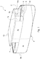
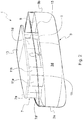
- FIG. 1 a pleasure craft according to a first embodiment of the invention is shown, which craft is indicated as a whole by reference 1.
- the craft 1 comprises a hull 3 in which a bow 3a, a stern 3b, and two flanks 3c, 3d connecting the bow 3a and the stern 3b on opposite sides of the hull 3 are defined.
- the craft 1 also comprises a deck 5 on which a superstructure 7 is provided, which is intended to accommodate one or more passenger cabins and/or a pilot house for the shipowner.
- the superstructure 7 is arranged on the deck 5 in an asymmetrical position with respect to the symmetry plane L of the craft 1, i.e. the plane which is perpendicular to the deck 5 and passes through the bow 3a and the middle point of the stern 3b.
- the outer perimeter of said superstructure 7 comprises: a first lateral wall 7c extending over a certain length along a first flank 3c of the hull between the bow and the stern, substantially aligned with said first flank of the hull; a first transverse wall 7a extending from the bow-facing end of said first lateral wall 7c in a direction substantially transverse to the symmetry plane L of the craft; a second transverse wall 7b extending from the stern-facing end of said first lateral wall 7c in a direction substantially transverse to the symmetry plane L of the craft; a second lateral wall 7d joining the ends of the transverse walls 7a, 7b opposite to those connected to the first lateral wall 7c.
- the distance between the lateral walls 7c, 7d of the superstructure 7 - or, in other words, the width W' of the superstructure 7 - along an axis transverse to the symmetry plane L of the craft is, at each point of the superstructure, smaller than the distance between the flanks 3c, 3d of the hull 3 - or, in other words, than the width W of the deck 5 - along an axis transverse to the symmetry plane L of the craft, so that a free lateral passageway 9 is left on the deck 5 between the second lateral wall 7d of the superstructure 7 and the second flank 3d of the hull 3.
- Said lateral passageway will have a width sufficient for allowing at least the passageway of an individual.
- said superstructure in order to obtain enough space within the superstructure 7, said superstructure will extend - in a direction perpendicular to the symmetry plane L - from the first flank 3c of the hull to the second flank 3d of the hull beyond said symmetry plane, at least along a substantial portion of its length.
- the superstructure 7 has not a uniform width in the direction perpendicular to the symmetry plane L of the craft, but has a reduced width, i.e. it is tapered, at least at one of its ends in the longitudinal direction.
- the superstructure 7 comprises a portion with a reduced width at its end facing the bow of the craft.
- the width of the first transverse wall 7a is smaller than the width of the second transverse wall 7b in a direction transverse to the symmetry plane L of the craft and the second lateral wall 7d comprises a first portion 7d' extending from the end of the second transvers wall 7b in a direction substantially parallel to the symmetry plane L of the craft and a second portion 7d" extending in an oblique direction and joining the first portion 7d' of the second lateral wall 7d to the first transverse wall 7a.
- the plan of the superstructure 7 has the shape of a rectangle with a superimposed scalene trapezoid having its smaller base facing the bow (see Figure 3 ).
- the second lateral wall 7d of the superstructure 7 could have a profile curved towards the bow.
- the first transverse wall 7a will have a width along an axis perpendicular to the symmetry plane L smaller than the maximum width W" of the superstructure 7, i.e. to the maximum distance between said first and second lateral walls of said superstructure along an axis perpendicular to the symmetry plane L.
- the pleasure craft 1 according to the invention has an overall structure which is strongly asymmetrical.
- Such asymmetry is relevant when the craft is viewed frontally (or from behind), i.e. in a direction parallel to the symmetry plane L (direction bow - stern).
- the asymmetrical arrangement of the superstructure 7 involves relevant practical advantages and, in particular, allows to increase the space available inside said structure if compared with a symmetrical arrangement with lateral passageways on both sides ("Walk Around" configuration). Specifically, for the same size of the deck, in the craft according to the invention the space inside the superstructure 7 can be 12 - 15% larger than in a "Walk Around" configuration.
- the asymmetrical arrangement of the superstructure 7 causes an imbalance from the aerodynamic point of view, since the portion of the craft between the symmetry plane L and the side 3c of the hull 3 (i.e. the portion completely occupied by the superstructure 7) offers a significantly higher resistance to air than the portion of the craft between the symmetry plane L and the opposite side 3d of the hull 3 (i.e. the portion only partially occupied by the superstructure 7) and different turbulences are created at the two opposite sides of the hull; the higher the craft speed is and the larger the craft size is, the more relevant are the effects of such imbalance.
- the asymmetrical arrangement of the superstructure 7 gives the craft 1 an awkward profile and generates in the observer an unpleasant impression from the aesthetical point of view.
- the pleasure craft 1 provides for the presence on the deck 5 of a bulkhead 11 which comprises at least a first wall 11a extending from the second flank 3d of the hull 3 in a direction substantially transverse to the symmetry plane L of the craft 1 and substantially coplanar to the first transverse wall 7a of the superstructure 7 and having such a width that the distance d of the end of said first wall 11a of said bulkhead 11 adjacent to the first transverse wall 7a of the superstructure 7 from the symmetry plane L of the craft is equal to or smaller than the maximum distance d' of the second lateral side 7d of the superstructure 7 from said symmetry plane L.
- the height of the first wall 11a of the bulkhead 11 is preferably substantially equal to the height of the walls 7a - 7d of the superstructure 7.
- the presence of the bulkhead 11 reduces the impression of strong asymmetry in the observer and generates a more pleasant impression in such observer.
- the superstructure 7 has a portion with a reduced width at its bow-facing end, i.e. near said first transverse wall 7a: thanks to this configuration, the lateral passageway 9 continuously extends from the stern to the bow, without the need of providing doors or passages in the first wall 11a of the bulkhead 11.
- said lateral passageway 9 comprises a first portion 9' extending along the first portion 7d' of the second lateral wall 7d, in a direction substantially parallel to the symmetry plane L of the craft, and a second portion 9" extending along the second portion 7d" of the second lateral wall 7d, in an oblique direction; the opening 9a of the lateral passageway 9 towards the bow, which extends between the first transverse wall of 7a of the superstructure 7 and the first wall 11a of the bulkhead 11, will be at a distance from the symmetry plane L of the craft smaller than the maximum distance between said symmetry plane L and the second lateral wall 7d of the superstructure 7.
- the opening 9a of the lateral passageway 9 is in a central position with respect to the direction transverse to the symmetry plane L (i.e. astride said symmetry plane), which further contributes to suppress asymmetries in the aerodynamic profile of the pleasure craft 1.
- the opening 9a of the lateral passageway 9 could be provided with a door (e.g. a sliding door or a swinging door) for increasing the symmetry of the structure.
- a door e.g. a sliding door or a swinging door
- the bulkhead 11 has a substantially "L"-shaped profile and comprises - besides the first wall 11a - a second wall 11b extending along the second flank 3d of the hull 3, in a direction substantially orthogonal to said first wall 11a and towards the stern 3b.
- said second wall 11b can advantageously hide the presence of an access door (not shown in the Figures) to the superstructure 7 in the second portion 7d" of the second lateral wall 7d to an external observer viewing the craft from the side.
- the bulkhead 11 will further comprise a third wall 11c extending parallel to the second portion 7d" of the second lateral wall 7d of the superstructure 7 and joining the free ends of said first and second walls 11a, 11b of said bulkhead.
- the free lateral passageway 9 will have a substantially uniform width over its entire length.
- volume enclosed by walls 11a - 11c of the bulkhead 11 can advantageously be used as storage space, for instance for berthing equipment and/or safety equipment.
- the craft 1 further comprises a overhead bridge or flying bridge 13 covering the superstructure 7 and extending in a direction transverse to the symmetry plane L of the craft, across the whole width of the deck 5.
- the bulkhead 11 acts as a support for the flying bridge 13, close to its bow-facing end, on the side of the deck opposite to that along which the superstructure 7 is arranged.
- An upright 15 can be provided for supporting the flying bridge 13 close to its stern-facing end.
- the bulkhead 11 plays an important structural role, since in its absence the flying bridge 13 would be cantilevered on the underlying superstructure 7, which would involve relevant bending stresses or the need of increasing the bearing structures, with a consequent increase in weight, or of adding unaesthetic, separate uprights.
- the bulkhead 11 is permanently, fixedly mounted on the deck 5.
- said bulkhead could be movably, or even removably, mounted on the deck 5.
- Said second embodiment differs from the previously described embodiment in that it provides for two bulkheads 11, 21, one at the bow-facing end of the superstructure 7 and the other one at the stern-facing end of the superstructure 7.
- the craft will offer a substantially continuous surface both at its bow and at its stern and the optical impression of a symmetrical surface will be very strong, both when viewing the craft frontally and when viewing it from behind.
- the superstructure 7 is arranged on the deck 5 in an asymmetrical position and the width of the superstructure 7 in a direction transverse to the symmetry plane L of the craft - i.e. the maximum distance between the lateral walls 7c, 7d of said superstructure - is, at each point of the superstructure 7, smaller than the width of the deck 5 in a direction transverse to the symmetry plane L of the craft, whereby a free lateral passageway 9 is left between the second lateral wall 7d of the superstructure 7 and the second flank 3d of the hull 3.
- the superstructure 7 comprises a first portion with reduced width at its bow-facing end and a second portion with reduced width at its stern-facing end.
- the second lateral wall 7d of said superstructure comprises a first, middle portion 7d' extending in a direction substantially parallel to the symmetry plane L of the craft, a second portion 7d" extending in an oblique direction and joining the first portion 7d' of the second lateral wall 7d to the first transverse wall 7a and a third portion 7d"' extending in an oblique direction and joining the first portion 7d' of the second lateral wall 7d to the second transverse wall 7b.
- a first bulkhead 11 which comprises at least a first wall 11a, substantially coplanar to the first transverse wall 7a of the superstructure 7 and extending from the second flank 3d of the hull 3 in a direction substantially transverse to the symmetry plane L of the craft 1 and having such a width that the distance of the end of said first wall 11a of said bulkhead 11 adjacent to the first transverse wall 7a of the superstructure 7 from the symmetry plane L of the craft is equal to or smaller than the maximum distance of the second lateral wall 7d of the superstructure 7 from said symmetry plane L; on the deck 5 a second bulkhead 21 is further provided, which comprises at least a first wall 21a, substantially coplanar to the second transverse wall 7b of the superstructure 7 and extending from the second flank 3d of the hull 3 in a direction substantially transverse to the symmetry plane L of the craft 1 and having such a width that the distance of the end of said first wall 21a of said bulkhead 21 adjacent to the second transverse wall 7
- the height of the first walls 11a, 21a of said bulkheads 11, 21 is preferably equal to the height of the walls 7a - 7d of the superstructure 7. Therefore, the lateral passageway 9 will continuously extend from the stern to the bow and comprise a middle portion 9' extending in a direction substantially parallel to the symmetry plane L of the craft, and oblique portions 9", 9'" extending along the second and third portions 7d", 7d"', respectively, of the second lateral wall 7d.
- the openings 9a, 9b of the lateral passageway 9 towards the bow and the stern will be at a distance from the symmetry plane L of the craft smaller than the maximum distance between said second lateral wall 7d of the superstructure 7 and said symmetry plane L.
- each bulkhead 11, 21 has a substantially "L"-shaped profile and comprises - besides the first wall 11a, 21 - a second wall 11b, 21b, extending along the second flank 3d of the hull 3, in a direction substantially orthogonal to said first wall 11a, 11b and towards the center of the superstructure 7, i.e. towards the stern and towards the bow, respectively.
- each bulkhead 11, 21 will further comprise a third wall 11c, 21c joining the free ends of the walls of each corresponding bulkhead and defining a corresponding enclosed volume which can be advantageously used as storage space.
- the bulkheads 11, 21 are permanently, fixedly mounted on the deck 5, but in an alternative embodiment they could be movably, or even removably, mounted on the deck 5.
- the craft 1 comprises a flying bridge 13 covering the superstructure 7 and extending in a direction transverse to the symmetry plane L of the craft across the whole width of the deck 5, the bulkheads 11, 21 act as supports for the flying bridge 13, both at the stern and at the bow, so that the flying bridge is not cantilevered on the underlying superstructure and there is no need for the presence of separate uprights or for an increase in the bearing structures, with a consequent increase of weight.
- the pleasure craft according to the invention allows to achieve the objects set forth above and combine the practical advantages deriving from an asymmetrical arrangement of the superstructure with a substantially symmetrical aerodynamic profile and a good directional stability and a pleasant appearance.
Landscapes
- Chemical & Material Sciences (AREA)
- Engineering & Computer Science (AREA)
- Combustion & Propulsion (AREA)
- Mechanical Engineering (AREA)
- Ocean & Marine Engineering (AREA)
- Physics & Mathematics (AREA)
- Fluid Mechanics (AREA)
- Vibration Prevention Devices (AREA)
- Toys (AREA)
- Bridges Or Land Bridges (AREA)
- Escalators And Moving Walkways (AREA)
- Developing Agents For Electrophotography (AREA)
- Diaphragms For Electromechanical Transducers (AREA)
- Catalysts (AREA)
- Table Devices Or Equipment (AREA)
- Buildings Adapted To Withstand Abnormal External Influences (AREA)
Description
- The present invention relates to a pleasure craft.
- More particularly, the present invention relates to a luxury pleasure craft, such as a yacht.
- Pleasure crafts are known which comprise a hull and a deck, on which a superstructure is provided, which can accommodate, for instance, the passenger cabin and/or the pilot house for the shipowner.
- In some known types of crafts, the aforementioned superstructure extends over the whole transverse width of the deck, so that the side walls of said superstructure are substantially aligned with the hull on both sides of the craft.
- This configuration (also known as "Full Beam") has the advantage that it allows to maximize the space inside the superstructure, thus allowing to obtain larger and more comfortable environments.
- However, as the superstructure extends over the whole width of the deck, this involves the need of passing through it or above it for moving from the deck stern to the deck bow, or vice versa. This is a major drawback, both from the point of view of practicality and from the point of view of users' privacy, particularly when the superstructure accommodates a passenger cabin.
- In other known types of crafts, the superstructure has a width smaller than that of the deck, so that lateral passageways or corridors are obtained on both sides of said superstructure, between its side walls and the side walls of the craft.
- This second configuration (also known as "Walk Around") has the advantage that it allows to easily move from the stern to the bow of the deck, without the need of passing through the superstructure.
- On the other hand, it involves a significant reduction in terms of space that can be utilized inside the superstructure with respect to a "Full Beam" configuration.
- In order to find a compromise between the two above-disclosed configurations, it is possible to provide one lateral passageway only for moving from the deck stern to the deck bow while remaining outside the superstructure: at one of the flanks of the craft, the lateral wall of the superstructure will be substantially flush with the hull; on the contrary, at the opposite flank of the craft, the superstructure will end before reaching the hull, leaving a free corridor on the deck between the opposite lateral wall of the superstructure and the side wall of the craft.
- This compromise solution on one hand allows greater practicality when moving from one area to the other area of the deck and on the other hand it provides - for a given size of the deck - a space inside the superstructure larger than in the case of a "Walk Around" configuration. Pleasure crafts comprising a superstructure designed in this way are disclosed, for instance, in documents
WO 2013/034935 andUS 4 064 584 . - However, even this solution is not free from drawbacks.
- In particular, the asymmetrical arrangement of the superstructure with respect to the hull involves an aerodynamic imbalance, since the craft has a frontal surface exposed to the air in the direction of navigation that is not symmetrical with respect to the hull, with the consequent formation of different turbulences on the two opposite sides of the hull. Consequently, rather than advancing straight forward, the craft has the tendency to turn towards the side on which the superstructure is arranged, i.e. towards the side on which it offers a greater resistance to the air. Consequently, in order to keep the ship advancing straight ahead, continuous corrections on the craft wheel are required.
- The higher the navigation speed is, the more evident is this disadvantage. Moreover, the larger the craft size is, the more evident is this disadvantage.
- Such disadvantage is to be avoided especially in luxury pleasure crafts (such as yachts), in which the high selling price should guarantee optimal performances.
- Moreover, if the craft is provided with a flying bridge over the superstructure, the asymmetrical arrangement causes said flying bridge to be cantilevered on the side of the lateral passageway, which can lead to possible phenomena of pressure fluctuations which have to be suppressed either by increasing the bearing structures, which would be penalizing in terms of weight, or by adding separate uprights (stanchions) which would be unaesthetic.
- Still, the asymmetrical arrangement of the superstructure with respect to the hull gives the craft a rough, awkward overall structure, which means an unpleasant appearance.
- The asymmetrical arrangement cannot be evidently perceived when the craft is viewed from the side. On the other hand, it is evident when the craft is viewed frontally or from behind, for instance when the craft is berthed, with its bow or stern towards the pier.
- Also in this case, this disadvantage has a remarkable importance in the case of yachts and similar luxury pleasure crafts, in which appearance is one of the parameters determining the success (or failure) of a model on the market.
- As a result, despite the practical advantages that can be obtained, a solution providing for an asymmetrical arrangement of the superstructure with respect to the deck is impracticable, at least as far as the application to luxury crafts such as yachts is concerned, in which high standards are required both from the technical point of view and from the aesthetic point of view.
- Document "X-Sym 125 Yacht with asymmetrical design and exclusive curves by S-move design | Tuvie" (www.tuvie.com/x-sym-125-yacht-with-asymmetrical-design-and-exclusive-curves-by-s-move-design"), as well as document "Beneteau Swift Trawler 30 - Reviews, performances, compare, price, warranty, specs, Reports Specifications Layout, video | BoatTEST.com" (www.boattest.com/review/beneteau/3493_swift-trawler-30") both disclose pleasure crafts incorporating both symmetrical and asymmetrical components.
- However, in the pleasure crafts shown in these documents the simultaneous provision of symmetrical and asymmetrical elements has a merely aesthetical purpose.
- None of these documents deals with the technical problem of eliminating the aerodynamic imbalance due to the fact that the craft has a frontal surface exposed to the air in the direction of navigation that is not symmetrical with respect to the hull.
- Accordingly, none these documents proposes a pleasure craft structure capable of effectively suppressing such aerodynamic imbalance.
- The main object of the present invention is to overcome the drawbacks of the prior art by providing a pleasure craft that allows to combine advantageous practical solutions with directional stability during navigation and a pleasing and attractive appearance. This and other objects are achieved by the pleasure craft as claimed in the appended claims.
- The pleasure craft according to the invention comprises a hull and a deck on which a superstructure is provided, which superstructure is arranged asymmetrically with respect to the symmetry plane - i.e. the plane arranged in the bow - stern direction - of said craft, so that at a first flank of the craft the lateral wall of the superstructure is substantially flush with the hull, while at the second, opposite flank a free passageway or corridor is left on the deck between the lateral wall of the superstructure and the side wall of the craft.
- Thanks to the fact that the invention provides for at least one bulkhead extending from said second flank of the hull in a direction substantially transverse to the symmetry plane of the craft and having a suitably chosen width, the front surface offered to the air in the direction of navigation does not substantially comprise any gap between said bulkhead and said superstructure.
- By virtue of such solution, any imbalance (even minimal) in the aerodynamic profile of the craft is compensated, and the craft shows no tendency to deviate from the predetermined route during navigation.
- Furthermore, always thanks to the bulkhead according to the invention, when an observer looks at the craft in a direction parallel to the symmetry plane of the craft itself, due to such solution, the optical effect on the observer is that of a substantially symmetrical overall structure.
- Therefore, thanks to the invention, the asymmetrical arrangement of the superstructure does not adversely affect either the aerodynamic profile or the aesthetic appearance of the craft and all the practical advantages resulting from this arrangement can be fully exploited while maintaining a directional stability during navigation (without the need for continuous corrections) and a prestige appearance.
- Said at least one bulkhead is substantially coplanar to one of the transverse walls of the superstructure, in particular the transverse wall on the bow side.
- In this way, the bulkhead acts as a deflector and gives, at its side of the hull, an aerodynamic behavior completely similar to that provided by the superstructure at the opposite side of said hull, thus eliminating (or at least drastically reducing) the imbalance in the aerodynamic profile.
- In a preferred embodiment of the invention, said at least one bulkhead is substantially "L"-shaped and comprises a first wall arranged substantially coplanar to one of the transverse walls of the superstructure, namely the transverse wall on the bow side, and a second wall arranged substantially orthogonal to the first wall and extending along the flank of the hull, towards the center of the superstructure.
- Indeed, experimental tests have shown that a bulkhead provided only with the first wall substantially coplanar to one of the transverse walls of the superstructure may not be sufficient for suppressing the tendency of the craft to deviate from the predetermined route, whereas in the case of a "L"-shaped bulkhead, the second wall extending along the flank of the hull effectively contributes to guarantee a satisfactory aerodynamic profile.
- In a preferred embodiment of the invention, two bulkheads are provided, one of which is substantially coplanar to the transverse wall of the superstructure on the bow side and the other one of which is substantially coplanar to the transverse wall of the superstructure on the stern side.
- In a particularly preferred variant of said embodiment, both said bulkheads are substantially "L"-shaped and comprise a first wall substantially coplanar to the corresponding transverse wall of the superstructure and a second wall substantially orthogonal to the first wall and extending along the flank of the hull, towards the center of the superstructure.
- In a preferred embodiment of the invention, a flying bridge is provided over the superstructure, said flying bridge extending transversely across the whole width of the bridge, from flank to flank of the craft: thanks to the presence of such flying bridge the asymmetrical arrangement of the superstructure is not visible when the craft is seen from above.
- Advantageously, when a flying bridge is provided, the at least one bulkhead of the craft according to the invention plays an important structural role, since it supports the side of the flying bridge opposite to that on which the superstructure is arranged: in the absence of such a bulkhead, the flying bridge would be cantilevered on the underlying (narrower) superstructure, which would result in considerable bending stresses or in the need of increasing the bearing structures, which would be penalizing in terms of weight, or of adding unaesthetic, separate uprights.
- Further features and advantages will be more evident from a detailed description of some preferred embodiments of the invention, given by way of non-limiting example with reference to the attached drawings, in which:
-
Figure 1 is a schematic perspective view of a pleasure craft according to a first embodiment of the invention; -
Figure 2 is a further schematic perspective view of the craft ofFigure 1 , seen from a different direction; -
Figure 3 is a plan view of the craft ofFigures 1 and2 ; -
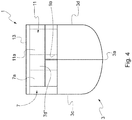
Figure 4 is a front view of the craft ofFigures 1 and2 ; -
Figure 5 is a schematic perspective view of a pleasure craft according to a second embodiment of the invention; -
Figure 6 is a plan view of the craft ofFigure 5 , in which the flying bridge has been removed for sake of clarity. - Referring to
Figures 1 to 4 , a pleasure craft according to a first embodiment of the invention is shown, which craft is indicated as a whole byreference 1. - The
craft 1 comprises ahull 3 in which abow 3a, astern 3b, and twoflanks bow 3a and thestern 3b on opposite sides of thehull 3 are defined. - The
craft 1 also comprises adeck 5 on which asuperstructure 7 is provided, which is intended to accommodate one or more passenger cabins and/or a pilot house for the shipowner. - According to the invention, the
superstructure 7 is arranged on thedeck 5 in an asymmetrical position with respect to the symmetry plane L of thecraft 1, i.e. the plane which is perpendicular to thedeck 5 and passes through thebow 3a and the middle point of thestern 3b. In particular, the outer perimeter of saidsuperstructure 7 comprises: a firstlateral wall 7c extending over a certain length along afirst flank 3c of the hull between the bow and the stern, substantially aligned with said first flank of the hull; a firsttransverse wall 7a extending from the bow-facing end of said firstlateral wall 7c in a direction substantially transverse to the symmetry plane L of the craft; a secondtransverse wall 7b extending from the stern-facing end of said firstlateral wall 7c in a direction substantially transverse to the symmetry plane L of the craft; a secondlateral wall 7d joining the ends of thetransverse walls lateral wall 7c. - The distance between the
lateral walls flanks lateral passageway 9 is left on thedeck 5 between the secondlateral wall 7d of thesuperstructure 7 and thesecond flank 3d of thehull 3. Said lateral passageway will have a width sufficient for allowing at least the passageway of an individual. - In any case, in order to obtain enough space within the
superstructure 7, said superstructure will extend - in a direction perpendicular to the symmetry plane L - from thefirst flank 3c of the hull to thesecond flank 3d of the hull beyond said symmetry plane, at least along a substantial portion of its length. - Moreover, for the reasons that will become apparent later, preferably the
superstructure 7 has not a uniform width in the direction perpendicular to the symmetry plane L of the craft, but has a reduced width, i.e. it is tapered, at least at one of its ends in the longitudinal direction. - More particularly, in the preferred embodiment shown in
Figures 1 to 4 , thesuperstructure 7 comprises a portion with a reduced width at its end facing the bow of the craft. Correspondingly, the width of the firsttransverse wall 7a is smaller than the width of the secondtransverse wall 7b in a direction transverse to the symmetry plane L of the craft and the secondlateral wall 7d comprises afirst portion 7d' extending from the end of thesecond transvers wall 7b in a direction substantially parallel to the symmetry plane L of the craft and asecond portion 7d" extending in an oblique direction and joining thefirst portion 7d' of the secondlateral wall 7d to the firsttransverse wall 7a. In other words, the plan of thesuperstructure 7 has the shape of a rectangle with a superimposed scalene trapezoid having its smaller base facing the bow (seeFigure 3 ). - This configuration is not to be intended as limiting and several different variants are possible. For instance, instead of being formed by two differently oriented portions, the second
lateral wall 7d of thesuperstructure 7 could have a profile curved towards the bow. - In general, the first
transverse wall 7a will have a width along an axis perpendicular to the symmetry plane L smaller than the maximum width W" of thesuperstructure 7, i.e. to the maximum distance between said first and second lateral walls of said superstructure along an axis perpendicular to the symmetry plane L. - From the above, it is evident that the
pleasure craft 1 according to the invention has an overall structure which is strongly asymmetrical. - Such asymmetry is relevant when the craft is viewed frontally (or from behind), i.e. in a direction parallel to the symmetry plane L (direction bow - stern).
- As mentioned above, the asymmetrical arrangement of the
superstructure 7 involves relevant practical advantages and, in particular, allows to increase the space available inside said structure if compared with a symmetrical arrangement with lateral passageways on both sides ("Walk Around" configuration). Specifically, for the same size of the deck, in the craft according to the invention the space inside thesuperstructure 7 can be 12 - 15% larger than in a "Walk Around" configuration. - However, the asymmetrical arrangement of the
superstructure 7 causes an imbalance from the aerodynamic point of view, since the portion of the craft between the symmetry plane L and theside 3c of the hull 3 (i.e. the portion completely occupied by the superstructure 7) offers a significantly higher resistance to air than the portion of the craft between the symmetry plane L and theopposite side 3d of the hull 3 (i.e. the portion only partially occupied by the superstructure 7) and different turbulences are created at the two opposite sides of the hull; the higher the craft speed is and the larger the craft size is, the more relevant are the effects of such imbalance. - Moreover, the asymmetrical arrangement of the
superstructure 7 gives thecraft 1 an awkward profile and generates in the observer an unpleasant impression from the aesthetical point of view. - In order to eliminate this imbalance in the aerodynamic profile and to hide the asymmetrical arrangement of the
superstructure 7, thepleasure craft 1 according to the invention provides for the presence on thedeck 5 of abulkhead 11 which comprises at least afirst wall 11a extending from thesecond flank 3d of thehull 3 in a direction substantially transverse to the symmetry plane L of thecraft 1 and substantially coplanar to the firsttransverse wall 7a of thesuperstructure 7 and having such a width that the distance d of the end of saidfirst wall 11a of saidbulkhead 11 adjacent to the firsttransverse wall 7a of thesuperstructure 7 from the symmetry plane L of the craft is equal to or smaller than the maximum distance d' of the secondlateral side 7d of thesuperstructure 7 from said symmetry plane L. - The height of the
first wall 11a of thebulkhead 11 is preferably substantially equal to the height of thewalls 7a - 7d of thesuperstructure 7. - Thanks to this solution, when the
craft 1 is viewed frontally, there is no gap between thewall 11a of thebulkhead 11 and thesuperstructure 7, said bulkhead acts as a deflector and the craft offers to the air a symmetrical, substantially continuous impact surface, thus eliminating any imbalance in the aerodynamic profile and giving, as a result, directional stability to the craft. - Moreover, the presence of the
bulkhead 11 reduces the impression of strong asymmetry in the observer and generates a more pleasant impression in such observer. - Considering the presence of the
bulkhead 11, it will be evident to the person skilled in the art why thesuperstructure 7 has a portion with a reduced width at its bow-facing end, i.e. near said firsttransverse wall 7a: thanks to this configuration, thelateral passageway 9 continuously extends from the stern to the bow, without the need of providing doors or passages in thefirst wall 11a of thebulkhead 11. More particularly, saidlateral passageway 9 comprises a first portion 9' extending along thefirst portion 7d' of the secondlateral wall 7d, in a direction substantially parallel to the symmetry plane L of the craft, and asecond portion 9" extending along thesecond portion 7d" of the secondlateral wall 7d, in an oblique direction; theopening 9a of thelateral passageway 9 towards the bow, which extends between the first transverse wall of 7a of thesuperstructure 7 and thefirst wall 11a of thebulkhead 11, will be at a distance from the symmetry plane L of the craft smaller than the maximum distance between said symmetry plane L and the secondlateral wall 7d of thesuperstructure 7. - Advantageously, as can be seen in
Figure 3 , theopening 9a of thelateral passageway 9 is in a central position with respect to the direction transverse to the symmetry plane L (i.e. astride said symmetry plane), which further contributes to suppress asymmetries in the aerodynamic profile of thepleasure craft 1. - As can be seen in
Figure 4 , notwithstanding the asymmetrical arrangement of thesuperstructure 7, when considering thepleasure craft 1 according to the invention frontally, it will be appreciated that it offers the best possible approximation of a continuous front surface, formed by - in sequence - the firsttransverse wall 7a of thesuperstructure 7, thesecond portion 7d" of the secondlateral wall 7d of said superstructure (visible behind theopening 9a of the lateral passageway 9) and thefirst wall 11a of thebulkhead 11. - The
opening 9a of thelateral passageway 9 could be provided with a door (e.g. a sliding door or a swinging door) for increasing the symmetry of the structure. - In the preferred embodiment shown in
Figures 1 to 4 , thebulkhead 11 has a substantially "L"-shaped profile and comprises - besides thefirst wall 11a - asecond wall 11b extending along thesecond flank 3d of thehull 3, in a direction substantially orthogonal to saidfirst wall 11a and towards the stern 3b. - The presence of said
second wall 11b contributes to "accompany" the air flow along theflank 3d of the hull, symmetrically to what occurs along theopposite flank 3c of the hull by virtue of the presence of thelateral wall 7c of thesuperstructure 7. - Moreover, said
second wall 11b can advantageously hide the presence of an access door (not shown in the Figures) to thesuperstructure 7 in thesecond portion 7d" of the secondlateral wall 7d to an external observer viewing the craft from the side. - Preferably, the
bulkhead 11 will further comprise athird wall 11c extending parallel to thesecond portion 7d" of the secondlateral wall 7d of thesuperstructure 7 and joining the free ends of said first andsecond walls - Thanks to this arrangement, the free
lateral passageway 9 will have a substantially uniform width over its entire length. - Moreover, the volume enclosed by
walls 11a - 11c of thebulkhead 11 can advantageously be used as storage space, for instance for berthing equipment and/or safety equipment. - In the embodiment shown in
Figures 1 to 4 , thecraft 1 further comprises a overhead bridge or flyingbridge 13 covering thesuperstructure 7 and extending in a direction transverse to the symmetry plane L of the craft, across the whole width of thedeck 5. - Thanks to the presence of this flying
bridge 13, the asymmetrical arrangement of thesuperstructure 7 is not visible when thecraft 1 according to the invention is seen from above. - Advantageously, in this embodiment the
bulkhead 11 acts as a support for the flyingbridge 13, close to its bow-facing end, on the side of the deck opposite to that along which thesuperstructure 7 is arranged. An upright 15 can be provided for supporting the flyingbridge 13 close to its stern-facing end. - In this embodiment, the
bulkhead 11 plays an important structural role, since in its absence the flyingbridge 13 would be cantilevered on theunderlying superstructure 7, which would involve relevant bending stresses or the need of increasing the bearing structures, with a consequent increase in weight, or of adding unaesthetic, separate uprights. - In a preferred embodiment of the invention, the
bulkhead 11 is permanently, fixedly mounted on thedeck 5. - However, in an alternative embodiment of the invention, said bulkhead could be movably, or even removably, mounted on the
deck 5. - With reference now to
Figures 5 and6 , a second embodiment of thepleasure craft 1 according to the invention is schematically shown. - Said second embodiment differs from the previously described embodiment in that it provides for two
bulkheads superstructure 7 and the other one at the stern-facing end of thesuperstructure 7. - Thanks to the presence of said two bulkheads, the craft will offer a substantially continuous surface both at its bow and at its stern and the optical impression of a symmetrical surface will be very strong, both when viewing the craft frontally and when viewing it from behind.
- In this second embodiment, too, the
superstructure 7 is arranged on thedeck 5 in an asymmetrical position and the width of thesuperstructure 7 in a direction transverse to the symmetry plane L of the craft - i.e. the maximum distance between thelateral walls superstructure 7, smaller than the width of thedeck 5 in a direction transverse to the symmetry plane L of the craft, whereby a freelateral passageway 9 is left between the secondlateral wall 7d of thesuperstructure 7 and thesecond flank 3d of thehull 3. - In this embodiment, the
superstructure 7 comprises a first portion with reduced width at its bow-facing end and a second portion with reduced width at its stern-facing end. Correspondingly, the secondlateral wall 7d of said superstructure comprises a first,middle portion 7d' extending in a direction substantially parallel to the symmetry plane L of the craft, asecond portion 7d" extending in an oblique direction and joining thefirst portion 7d' of the secondlateral wall 7d to the firsttransverse wall 7a and athird portion 7d"' extending in an oblique direction and joining thefirst portion 7d' of the secondlateral wall 7d to the secondtransverse wall 7b. In this embodiment, on the deck 5 afirst bulkhead 11 is provided, which comprises at least afirst wall 11a, substantially coplanar to the firsttransverse wall 7a of thesuperstructure 7 and extending from thesecond flank 3d of thehull 3 in a direction substantially transverse to the symmetry plane L of thecraft 1 and having such a width that the distance of the end of saidfirst wall 11a of saidbulkhead 11 adjacent to the firsttransverse wall 7a of thesuperstructure 7 from the symmetry plane L of the craft is equal to or smaller than the maximum distance of the secondlateral wall 7d of thesuperstructure 7 from said symmetry plane L; on the deck 5 asecond bulkhead 21 is further provided, which comprises at least afirst wall 21a, substantially coplanar to the secondtransverse wall 7b of thesuperstructure 7 and extending from thesecond flank 3d of thehull 3 in a direction substantially transverse to the symmetry plane L of thecraft 1 and having such a width that the distance of the end of saidfirst wall 21a of saidbulkhead 21 adjacent to the secondtransverse wall 7b of thesuperstructure 7 from the symmetry plane L of the craft is equal to or smaller than the maximum distance of the secondlateral wall 7d of thesuperstructure 7 from said symmetry plane L. - The height of the
first walls bulkheads walls 7a - 7d of thesuperstructure 7. Therefore, thelateral passageway 9 will continuously extend from the stern to the bow and comprise a middle portion 9' extending in a direction substantially parallel to the symmetry plane L of the craft, andoblique portions 9", 9'" extending along the second andthird portions 7d", 7d"', respectively, of the secondlateral wall 7d. Theopenings lateral passageway 9 towards the bow and the stern will be at a distance from the symmetry plane L of the craft smaller than the maximum distance between said secondlateral wall 7d of thesuperstructure 7 and said symmetry plane L. - As a result, notwithstanding the asymmetrical arrangement of the
superstructure 7, the observer viewing thepleasure craft 1 according to the invention frontally or from behind will get the impression of a continuous surface. - In this embodiment, too, each
bulkhead first wall 11a, 21 - asecond wall second flank 3d of thehull 3, in a direction substantially orthogonal to saidfirst wall superstructure 7, i.e. towards the stern and towards the bow, respectively. Preferably, eachbulkhead third wall - In this embodiment, too, the
bulkheads deck 5, but in an alternative embodiment they could be movably, or even removably, mounted on thedeck 5. - If the
craft 1 comprises a flyingbridge 13 covering thesuperstructure 7 and extending in a direction transverse to the symmetry plane L of the craft across the whole width of thedeck 5, thebulkheads bridge 13, both at the stern and at the bow, so that the flying bridge is not cantilevered on the underlying superstructure and there is no need for the presence of separate uprights or for an increase in the bearing structures, with a consequent increase of weight. - With particular reference to
Figure 6 , some preferred proportions between the different elements of the craft according to the invention (more particularly between thesuperstructure 7 and thebulkheads 11, 21) are provided, which proportions should in no way be intended as limiting: - the ratio between the distance of the end of the first
transverse wall 7a of thesuperstructure 7 from the symmetry plane L (segment ED inFigure 6 ) and the corresponding distance of thesecond flank 3d of thehull 3 from said symmetry plane L (segment EB inFigure 6 ) is comprised between 0,3 and 0,6; said ratio can be considered as an "asymmetry index" of the configuration of the craft according to the invention; - the minimum width of the
first wall 11a of thebulkhead 11 is equal to the distance between thesecond flank 3d of thehull 3 and the projection of the point farthest from the symmetry plane L of the secondlateral wall 7d of the superstructure 7 (A) on saidfirst wall 11a of thebulkhead 11 and therefore corresponds to segment A'B inFigure 6 ; the width of thefirst wall 11a of the bulkhead 11 (segment CB' inFigure 6 ) is preferably equal to said minimum width plus a so-called "covering factor" (segment CA' inFigure 6 ); - said "covering factor" (segment CA' in
Figure 6 ) is preferably equal to 15 - 40% of the distance between the end of the firsttransverse wall 7a of thesuperstructure 7 and the projection of the point farthest from the symmetry plane L of the secondlateral wall 7d of the superstructure 7 (A) on thefirst wall 11a of the bulkhead 11 (segment DA' inFigure 6 ); - the angle α formed between the
second oblique portion 9" of thelateral passageway 9 and the first portion 9' of said lateral passageway - i.e. and the symmetry plane L of the craft 1 - is preferably equal to 20 - 45°; - the ratio between the width b1 of the
second oblique portion 9" of thelateral passageway 9 and the width b of the first portion 9' of said lateral passageway is preferably comprised between 0,9 and 1,1. - Similar proportions can also be provided for the
second bulkhead 21. - It will be evident from the above that the pleasure craft according to the invention allows to achieve the objects set forth above and combine the practical advantages deriving from an asymmetrical arrangement of the superstructure with a substantially symmetrical aerodynamic profile and a good directional stability and a pleasant appearance.
- It will also be evident to the person skilled in the art that the detailed description provided above has been given by way of non-limiting example and several modifications and variants are possible without departing from the scope of protection as defined by the appended claims.
Claims (12)
- Pleasure craft (1), comprising:- a hull (3), including a bow (3a), a stern (3b), a symmetry plane (L) and two flanks (3c, 3d) connecting said bow (3a) to said stern (3b) on opposite sides of said hull relative to the symmetry plane (L);- a deck (5) substantially perpendicular to the symmetry plane;- a superstructure (7) arranged on said deck (5), the outer perimeter of said superstructure comprising a first lateral wall (7c) extending over a first flank (3c) of said hull in a direction substantially parallel to the symmetry plane (L) of said craft and is substantially aligned with said first flank of said hull, a first transverse wall (7a) extending from the end of said first lateral wall (7c) facing towards the bow (3a) in a plane substantially transverse to the symmetry plane (L) of said craft, a second transverse wall (7b) extending from the end of said first lateral wall (7c) facing towards the stern (3b) in a plane substantially transverse to the symmetry plane (L) of said craft, and a second lateral wall (7d) connecting the ends of said first and second transverse walls (7a, 7b) opposite to the ends thereof connected to said first lateral wall (7c),
wherein the width (W') between said first and said second lateral walls (7c, 7d) of said superstructure along an axis perpendicular to the symmetry plane is smaller than the width (W) between said first and said second flanks (3c, 3d) of said hull along the same axis, a lateral passageway (9) being thus defined between said second lateral wall (7d) of said superstructure (7) and said second flank (3d) of said hull (3),
wherein the width along an axis perpendicular to the symmetry plane of at least said first transverse wall (7a) of the superstructure is smaller than the maximum width (W") between said first and said second lateral walls (7c, 7d) of said superstructure,
characterized in that at least one bulkhead (11) is arranged on said deck (5), said bulkhead comprising at least a first wall (11a) extending from said second flank (3d) of said hull (3) and being substantially coplanar with said first transverse wall (7a) of said superstructure, wherein said first wall (11a) of said bulkhead (11) has such a width along an axis perpendicular to said symmetry plane (L) that the distance (d) of the end of said first wall (11a) of said bulkhead (11) adjacent to said first transverse wall from said symmetry plane (L) is equal to or smaller than the maximum distance (d') of said second lateral wall (7d) of said superstructure (7) from said symmetry plane (L), and in that said transverse walls (7a, 7b) and said lateral walls (7c, 7d) of said superstructure (7) all have the same height and wherein the height of said first wall (11a) of said bulkhead (11) is substantially the same as the height of said walls (7a - 7d) of said superstructure. - Pleasure craft (1) according to claim 1, wherein said superstructure (7) has a portion having a smaller width near said first transverse wall (7a).
- Pleasure craft (1) according to claim 1, wherein said bulkhead (11) further comprises a second wall (11b) which extends towards said stern (3b) in a direction substantially orthogonal to said first wall (11a) of said bulkhead and is substantially aligned with said second flank (3d) of said hull.
- Pleasure craft (1) according to claim 1, wherein a second bulkhead (21) is further provided on said deck (5), which second bulkhead comprises at least a first wall (21a) extending from said second flank (3d) of said hull (3) and being substantially coplanar with said second transverse wall (7b) of said superstructure (7), wherein said first wall (21a) of said second bulkhead (21) has such a width along an axis perpendicular to said symmetry plane (L) that the distance (d) of the end of said first wall (21a) of said second bulkhead (21) adjacent to said second transverse wall from said symmetry plane (L) is equal to or smaller than the maximum distance (d') of said second lateral wall (7d) of said superstructure (7) from said symmetry plane (L).
- Pleasure craft (1) according to claim 4, wherein said transverse walls (7a, 7b) and said lateral walls (7c, 7d) of said superstructure (7) all have the same height and wherein the height of said first wall (21a) of said second bulkhead (21) is substantially the same as the height of said walls (7a - 7d) of said superstructure.
- Pleasure craft (1) according to claim 4, wherein said superstructure (7) has a second portion having a smaller width near said second transverse wall (7b).
- Pleasure craft (1) according to claim 4, wherein said second bulkhead (21) further comprises a second wall (21b) which extends towards said bow (3a) in a direction substantially orthogonal to said first wall (21a) of said bulkhead and is substantially aligned with said second flank (3d) of said hull.
- Pleasure craft (1) according to claim 3, wherein said bulkhead (11) further comprises a third wall (11c) joining the free ends of said first and said second walls (11a, 11b) of said bulkhead.
- Pleasure craft (1) according to claim 7, wherein said second bulkhead (21) further comprises a third wall (21c) joining the free ends of said first and said second walls (21a, 21b) of said bulkhead.
- Pleasure craft (1) according to any of the claims 1 - 9, wherein said bulkhead (11) and, if provided, said second bulkhead (21) is/are fixedly and permanently mounted on said deck (5).
- Pleasure craft (1) according to any of the claims 1 - 9, wherein said bulkhead (11) and, if provided, said second bulkhead (21) is/are movably and/or removably mounted on said deck (5).
- Pleasure craft (1) according to any of the preceding claims, wherein said craft (1) comprises a flying bridge (13) covering said superstructure (7) and extending in a direction transverse to the symmetry plane (L) of the craft across the entire width of said deck (5) and wherein said bulkhead (11) and, if provided, said second bulkhead (21) act(s) as a support for said flying bridge (13).
Priority Applications (1)
| Application Number | Priority Date | Filing Date | Title |
|---|---|---|---|
| PL17787246T PL3472034T3 (en) | 2016-06-15 | 2017-06-07 | Pleasure craft |
Applications Claiming Priority (2)
| Application Number | Priority Date | Filing Date | Title |
|---|---|---|---|
| ITUA2016A004403A ITUA20164403A1 (en) | 2016-06-15 | 2016-06-15 | Pleasure boat |
| PCT/IB2017/053347 WO2017216684A1 (en) | 2016-06-15 | 2017-06-07 | Pleasure craft |
Publications (2)
| Publication Number | Publication Date |
|---|---|
| EP3472034A1 EP3472034A1 (en) | 2019-04-24 |
| EP3472034B1 true EP3472034B1 (en) | 2020-05-13 |
Family
ID=57209694
Family Applications (1)
| Application Number | Title | Priority Date | Filing Date |
|---|---|---|---|
| EP17787246.2A Active EP3472034B1 (en) | 2016-06-15 | 2017-06-07 | Pleasure craft |
Country Status (12)
| Country | Link |
|---|---|
| EP (1) | EP3472034B1 (en) |
| KR (1) | KR102279527B1 (en) |
| CN (1) | CN109328160B (en) |
| AU (1) | AU2017286768B2 (en) |
| BR (1) | BR112018076170B1 (en) |
| DE (1) | DE202017007156U1 (en) |
| ES (1) | ES2805033T3 (en) |
| IT (1) | ITUA20164403A1 (en) |
| MX (1) | MX2018015395A (en) |
| PL (1) | PL3472034T3 (en) |
| RU (1) | RU2706759C1 (en) |
| WO (1) | WO2017216684A1 (en) |
Family Cites Families (11)
| Publication number | Priority date | Publication date | Assignee | Title |
|---|---|---|---|---|
| GB1180107A (en) * | 1967-07-25 | 1970-02-04 | Dartmouth Aero Marine Ltd | Improvements in and relating to Yachts. |
| US4064584A (en) * | 1976-09-13 | 1977-12-27 | James Harold Funkhouser | Upper boat deck |
| IT1227143B (en) * | 1988-09-26 | 1991-03-19 | Fincantieri Cantieri Navali It | PASSENGER SHIP WITH DISTINCT FREE WALL SPACES |
| FR2831133B1 (en) * | 2001-10-23 | 2004-01-23 | Laurent Maurice Mermier | LARGE WIDTH CRUISE OR LEISURE VESSEL |
| KR100507853B1 (en) * | 2002-12-17 | 2005-08-17 | 허식 | Self-propelling barge |
| FI20095055A0 (en) * | 2009-01-23 | 2009-01-23 | Stx Finland Cruise Oy | Floating structure, ship, or similar |
| FR2974346B1 (en) * | 2011-04-22 | 2013-05-24 | Stx France Sa | PASSENGER SHIP WITH SUPERSTRUCTURE EQUIPPED WITH AT LEAST ONE ARK |
| CN202414090U (en) * | 2011-12-30 | 2012-09-05 | 广东江龙船舶制造有限公司 | Aluminum Alloy-FRP Composite Ship |
| CN202642045U (en) * | 2012-06-27 | 2013-01-02 | 安庆三维电器有限公司 | Integrated kitchen used for ships |
| CN202966577U (en) * | 2012-12-18 | 2013-06-05 | 广东江龙船舶制造有限公司 | Steel-FRP Composite Ship |
| CN205150156U (en) * | 2015-10-23 | 2016-04-13 | 上海船舶研究设计院 | Novel superstructure cabin structure of boats and ships |
-
2016
- 2016-06-15 IT ITUA2016A004403A patent/ITUA20164403A1/en unknown
-
2017
- 2017-06-07 EP EP17787246.2A patent/EP3472034B1/en active Active
- 2017-06-07 ES ES17787246T patent/ES2805033T3/en active Active
- 2017-06-07 CN CN201780037558.9A patent/CN109328160B/en active Active
- 2017-06-07 RU RU2018144343A patent/RU2706759C1/en active
- 2017-06-07 BR BR112018076170-2A patent/BR112018076170B1/en active IP Right Grant
- 2017-06-07 PL PL17787246T patent/PL3472034T3/en unknown
- 2017-06-07 DE DE202017007156.8U patent/DE202017007156U1/en active Active
- 2017-06-07 KR KR1020187036033A patent/KR102279527B1/en active Active
- 2017-06-07 AU AU2017286768A patent/AU2017286768B2/en active Active
- 2017-06-07 MX MX2018015395A patent/MX2018015395A/en unknown
- 2017-06-07 WO PCT/IB2017/053347 patent/WO2017216684A1/en not_active Ceased
Non-Patent Citations (1)
| Title |
|---|
| None * |
Also Published As
| Publication number | Publication date |
|---|---|
| KR102279527B1 (en) | 2021-07-20 |
| EP3472034A1 (en) | 2019-04-24 |
| RU2706759C1 (en) | 2019-11-20 |
| WO2017216684A1 (en) | 2017-12-21 |
| ITUA20164403A1 (en) | 2017-12-15 |
| BR112018076170B1 (en) | 2023-12-26 |
| CN109328160B (en) | 2021-03-26 |
| AU2017286768B2 (en) | 2022-03-31 |
| PL3472034T3 (en) | 2021-06-14 |
| AU2017286768A1 (en) | 2018-12-13 |
| KR20190018430A (en) | 2019-02-22 |
| NZ748636A (en) | 2021-03-26 |
| DE202017007156U1 (en) | 2019-10-14 |
| CN109328160A (en) | 2019-02-12 |
| MX2018015395A (en) | 2019-04-29 |
| ES2805033T3 (en) | 2021-02-10 |
| BR112018076170A2 (en) | 2019-03-26 |
Similar Documents
| Publication | Publication Date | Title |
|---|---|---|
| AU2012305681B2 (en) | Water craft having open upper deck, aft swim deck and collapsible bulwarks | |
| ES2451500T3 (en) | Provision of a bow of a vessel of the displacement type | |
| EP3305651A1 (en) | Articulated tug barge hull | |
| AU2017286768B2 (en) | Pleasure craft | |
| NZ748636B2 (en) | Pleasure craft | |
| WO2011117906A1 (en) | Planing hull with innovative bottom | |
| WO2018150912A1 (en) | Hull structure | |
| JP5385195B2 (en) | Ship | |
| WO2017081996A1 (en) | Ship | |
| US20220153391A1 (en) | Wake enhancing boat hull | |
| US6755143B2 (en) | Wide cruise ship or pleasure boat | |
| WO2016158880A1 (en) | Vessel | |
| US5072681A (en) | Passenger ship | |
| US12559203B2 (en) | Pleasure craft having an improved deck construction | |
| JP2012017022A (en) | Wind pressure resistance reducing structure for ship, and the ship | |
| NL2018697B1 (en) | Vessel | |
| JP2013154756A (en) | Multi-hull ship | |
| JP3949895B2 (en) | Fully enclosed Funabashi Wing | |
| US20070261623A1 (en) | Multi-hull boat | |
| JPS6154397A (en) | 2-shaft 2-rudder system high speed ship | |
| GB2503412A (en) | Floating vessel with widened deck area at its bow end | |
| JPH0528797U (en) | Planing high speed boat | |
| Yun et al. | Seakeeping | |
| CA2944301A1 (en) | Articulating tug barge hull | |
| Miskovic | Product Analysis and Design of a Superyacht Analysis of a semi-custom fiberglass range of Benetti Yachts, from 93’to 145’Redesign of a “Classic” 121’Yacht |
Legal Events
| Date | Code | Title | Description |
|---|---|---|---|
| REG | Reference to a national code |
Ref country code: DE Ref legal event code: R138 Ref document number: 202017007156 Country of ref document: DE Free format text: GERMAN DOCUMENT NUMBER IS 602017016797 |
|
| STAA | Information on the status of an ep patent application or granted ep patent |
Free format text: STATUS: UNKNOWN |
|
| STAA | Information on the status of an ep patent application or granted ep patent |
Free format text: STATUS: THE INTERNATIONAL PUBLICATION HAS BEEN MADE |
|
| PUAI | Public reference made under article 153(3) epc to a published international application that has entered the european phase |
Free format text: ORIGINAL CODE: 0009012 |
|
| STAA | Information on the status of an ep patent application or granted ep patent |
Free format text: STATUS: REQUEST FOR EXAMINATION WAS MADE |
|
| 17P | Request for examination filed |
Effective date: 20181211 |
|
| AK | Designated contracting states |
Kind code of ref document: A1 Designated state(s): AL AT BE BG CH CY CZ DE DK EE ES FI FR GB GR HR HU IE IS IT LI LT LU LV MC MK MT NL NO PL PT RO RS SE SI SK SM TR |
|
| AX | Request for extension of the european patent |
Extension state: BA ME |
|
| DAV | Request for validation of the european patent (deleted) | ||
| DAX | Request for extension of the european patent (deleted) | ||
| GRAP | Despatch of communication of intention to grant a patent |
Free format text: ORIGINAL CODE: EPIDOSNIGR1 |
|
| STAA | Information on the status of an ep patent application or granted ep patent |
Free format text: STATUS: GRANT OF PATENT IS INTENDED |
|
| INTG | Intention to grant announced |
Effective date: 20191210 |
|
| GRAS | Grant fee paid |
Free format text: ORIGINAL CODE: EPIDOSNIGR3 |
|
| GRAA | (expected) grant |
Free format text: ORIGINAL CODE: 0009210 |
|
| STAA | Information on the status of an ep patent application or granted ep patent |
Free format text: STATUS: THE PATENT HAS BEEN GRANTED |
|
| AK | Designated contracting states |
Kind code of ref document: B1 Designated state(s): AL AT BE BG CH CY CZ DE DK EE ES FI FR GB GR HR HU IE IS IT LI LT LU LV MC MK MT NL NO PL PT RO RS SE SI SK SM TR |
|
| REG | Reference to a national code |
Ref country code: GB Ref legal event code: FG4D |
|
| REG | Reference to a national code |
Ref country code: CH Ref legal event code: EP |
|
| REG | Reference to a national code |
Ref country code: DE Ref legal event code: R096 Ref document number: 602017016797 Country of ref document: DE |
|
| REG | Reference to a national code |
Ref country code: AT Ref legal event code: REF Ref document number: 1269914 Country of ref document: AT Kind code of ref document: T Effective date: 20200615 |
|
| REG | Reference to a national code |
Ref country code: NL Ref legal event code: FP |
|
| REG | Reference to a national code |
Ref country code: LT Ref legal event code: MG4D |
|
| REG | Reference to a national code |
Ref country code: GR Ref legal event code: EP Ref document number: 20200402170 Country of ref document: GR Effective date: 20201014 |
|
| PG25 | Lapsed in a contracting state [announced via postgrant information from national office to epo] |
Ref country code: PT Free format text: LAPSE BECAUSE OF FAILURE TO SUBMIT A TRANSLATION OF THE DESCRIPTION OR TO PAY THE FEE WITHIN THE PRESCRIBED TIME-LIMIT Effective date: 20200914 Ref country code: IS Free format text: LAPSE BECAUSE OF FAILURE TO SUBMIT A TRANSLATION OF THE DESCRIPTION OR TO PAY THE FEE WITHIN THE PRESCRIBED TIME-LIMIT Effective date: 20200913 Ref country code: SE Free format text: LAPSE BECAUSE OF FAILURE TO SUBMIT A TRANSLATION OF THE DESCRIPTION OR TO PAY THE FEE WITHIN THE PRESCRIBED TIME-LIMIT Effective date: 20200513 Ref country code: FI Free format text: LAPSE BECAUSE OF FAILURE TO SUBMIT A TRANSLATION OF THE DESCRIPTION OR TO PAY THE FEE WITHIN THE PRESCRIBED TIME-LIMIT Effective date: 20200513 Ref country code: NO Free format text: LAPSE BECAUSE OF FAILURE TO SUBMIT A TRANSLATION OF THE DESCRIPTION OR TO PAY THE FEE WITHIN THE PRESCRIBED TIME-LIMIT Effective date: 20200813 Ref country code: LT Free format text: LAPSE BECAUSE OF FAILURE TO SUBMIT A TRANSLATION OF THE DESCRIPTION OR TO PAY THE FEE WITHIN THE PRESCRIBED TIME-LIMIT Effective date: 20200513 |
|
| PG25 | Lapsed in a contracting state [announced via postgrant information from national office to epo] |
Ref country code: BG Free format text: LAPSE BECAUSE OF FAILURE TO SUBMIT A TRANSLATION OF THE DESCRIPTION OR TO PAY THE FEE WITHIN THE PRESCRIBED TIME-LIMIT Effective date: 20200813 Ref country code: RS Free format text: LAPSE BECAUSE OF FAILURE TO SUBMIT A TRANSLATION OF THE DESCRIPTION OR TO PAY THE FEE WITHIN THE PRESCRIBED TIME-LIMIT Effective date: 20200513 Ref country code: HR Free format text: LAPSE BECAUSE OF FAILURE TO SUBMIT A TRANSLATION OF THE DESCRIPTION OR TO PAY THE FEE WITHIN THE PRESCRIBED TIME-LIMIT Effective date: 20200513 Ref country code: LV Free format text: LAPSE BECAUSE OF FAILURE TO SUBMIT A TRANSLATION OF THE DESCRIPTION OR TO PAY THE FEE WITHIN THE PRESCRIBED TIME-LIMIT Effective date: 20200513 |
|
| REG | Reference to a national code |
Ref country code: AT Ref legal event code: MK05 Ref document number: 1269914 Country of ref document: AT Kind code of ref document: T Effective date: 20200513 |
|
| PG25 | Lapsed in a contracting state [announced via postgrant information from national office to epo] |
Ref country code: AL Free format text: LAPSE BECAUSE OF FAILURE TO SUBMIT A TRANSLATION OF THE DESCRIPTION OR TO PAY THE FEE WITHIN THE PRESCRIBED TIME-LIMIT Effective date: 20200513 |
|
| PG25 | Lapsed in a contracting state [announced via postgrant information from national office to epo] |
Ref country code: SM Free format text: LAPSE BECAUSE OF FAILURE TO SUBMIT A TRANSLATION OF THE DESCRIPTION OR TO PAY THE FEE WITHIN THE PRESCRIBED TIME-LIMIT Effective date: 20200513 Ref country code: EE Free format text: LAPSE BECAUSE OF FAILURE TO SUBMIT A TRANSLATION OF THE DESCRIPTION OR TO PAY THE FEE WITHIN THE PRESCRIBED TIME-LIMIT Effective date: 20200513 Ref country code: IT Free format text: LAPSE BECAUSE OF FAILURE TO SUBMIT A TRANSLATION OF THE DESCRIPTION OR TO PAY THE FEE WITHIN THE PRESCRIBED TIME-LIMIT Effective date: 20200513 Ref country code: AT Free format text: LAPSE BECAUSE OF FAILURE TO SUBMIT A TRANSLATION OF THE DESCRIPTION OR TO PAY THE FEE WITHIN THE PRESCRIBED TIME-LIMIT Effective date: 20200513 Ref country code: DK Free format text: LAPSE BECAUSE OF FAILURE TO SUBMIT A TRANSLATION OF THE DESCRIPTION OR TO PAY THE FEE WITHIN THE PRESCRIBED TIME-LIMIT Effective date: 20200513 Ref country code: CZ Free format text: LAPSE BECAUSE OF FAILURE TO SUBMIT A TRANSLATION OF THE DESCRIPTION OR TO PAY THE FEE WITHIN THE PRESCRIBED TIME-LIMIT Effective date: 20200513 Ref country code: RO Free format text: LAPSE BECAUSE OF FAILURE TO SUBMIT A TRANSLATION OF THE DESCRIPTION OR TO PAY THE FEE WITHIN THE PRESCRIBED TIME-LIMIT Effective date: 20200513 |
|
| REG | Reference to a national code |
Ref country code: CH Ref legal event code: PL |
|
| REG | Reference to a national code |
Ref country code: ES Ref legal event code: FG2A Ref document number: 2805033 Country of ref document: ES Kind code of ref document: T3 Effective date: 20210210 |
|
| REG | Reference to a national code |
Ref country code: DE Ref legal event code: R097 Ref document number: 602017016797 Country of ref document: DE |
|
| PG25 | Lapsed in a contracting state [announced via postgrant information from national office to epo] |
Ref country code: SK Free format text: LAPSE BECAUSE OF FAILURE TO SUBMIT A TRANSLATION OF THE DESCRIPTION OR TO PAY THE FEE WITHIN THE PRESCRIBED TIME-LIMIT Effective date: 20200513 Ref country code: MC Free format text: LAPSE BECAUSE OF FAILURE TO SUBMIT A TRANSLATION OF THE DESCRIPTION OR TO PAY THE FEE WITHIN THE PRESCRIBED TIME-LIMIT Effective date: 20200513 |
|
| PLBE | No opposition filed within time limit |
Free format text: ORIGINAL CODE: 0009261 |
|
| STAA | Information on the status of an ep patent application or granted ep patent |
Free format text: STATUS: NO OPPOSITION FILED WITHIN TIME LIMIT |
|
| PG25 | Lapsed in a contracting state [announced via postgrant information from national office to epo] |
Ref country code: LU Free format text: LAPSE BECAUSE OF NON-PAYMENT OF DUE FEES Effective date: 20200607 |
|
| REG | Reference to a national code |
Ref country code: BE Ref legal event code: MM Effective date: 20200630 |
|
| 26N | No opposition filed |
Effective date: 20210216 |
|
| PG25 | Lapsed in a contracting state [announced via postgrant information from national office to epo] |
Ref country code: LI Free format text: LAPSE BECAUSE OF NON-PAYMENT OF DUE FEES Effective date: 20200630 Ref country code: IE Free format text: LAPSE BECAUSE OF NON-PAYMENT OF DUE FEES Effective date: 20200607 Ref country code: CH Free format text: LAPSE BECAUSE OF NON-PAYMENT OF DUE FEES Effective date: 20200630 |
|
| PG25 | Lapsed in a contracting state [announced via postgrant information from national office to epo] |
Ref country code: BE Free format text: LAPSE BECAUSE OF NON-PAYMENT OF DUE FEES Effective date: 20200630 Ref country code: SI Free format text: LAPSE BECAUSE OF FAILURE TO SUBMIT A TRANSLATION OF THE DESCRIPTION OR TO PAY THE FEE WITHIN THE PRESCRIBED TIME-LIMIT Effective date: 20200513 |
|
| PG25 | Lapsed in a contracting state [announced via postgrant information from national office to epo] |
Ref country code: MT Free format text: LAPSE BECAUSE OF FAILURE TO SUBMIT A TRANSLATION OF THE DESCRIPTION OR TO PAY THE FEE WITHIN THE PRESCRIBED TIME-LIMIT Effective date: 20200513 Ref country code: CY Free format text: LAPSE BECAUSE OF FAILURE TO SUBMIT A TRANSLATION OF THE DESCRIPTION OR TO PAY THE FEE WITHIN THE PRESCRIBED TIME-LIMIT Effective date: 20200513 |
|
| PG25 | Lapsed in a contracting state [announced via postgrant information from national office to epo] |
Ref country code: MK Free format text: LAPSE BECAUSE OF FAILURE TO SUBMIT A TRANSLATION OF THE DESCRIPTION OR TO PAY THE FEE WITHIN THE PRESCRIBED TIME-LIMIT Effective date: 20200513 |
|
| P01 | Opt-out of the competence of the unified patent court (upc) registered |
Effective date: 20230518 |
|
| PGFP | Annual fee paid to national office [announced via postgrant information from national office to epo] |
Ref country code: DE Payment date: 20250620 Year of fee payment: 9 Ref country code: PL Payment date: 20250605 Year of fee payment: 9 |
|
| PGFP | Annual fee paid to national office [announced via postgrant information from national office to epo] |
Ref country code: GB Payment date: 20250625 Year of fee payment: 9 |
|
| PGFP | Annual fee paid to national office [announced via postgrant information from national office to epo] |
Ref country code: NL Payment date: 20250627 Year of fee payment: 9 |
|
| PGFP | Annual fee paid to national office [announced via postgrant information from national office to epo] |
Ref country code: FR Payment date: 20250522 Year of fee payment: 9 |
|
| PGFP | Annual fee paid to national office [announced via postgrant information from national office to epo] |
Ref country code: GR Payment date: 20250626 Year of fee payment: 9 |
|
| PGFP | Annual fee paid to national office [announced via postgrant information from national office to epo] |
Ref country code: TR Payment date: 20250602 Year of fee payment: 9 |
|
| PGFP | Annual fee paid to national office [announced via postgrant information from national office to epo] |
Ref country code: ES Payment date: 20250828 Year of fee payment: 9 |