EP3471914B1 - Stahlblechbremskolben fur eine hydraulische bremse - Google Patents
Stahlblechbremskolben fur eine hydraulische bremse Download PDFInfo
- Publication number
- EP3471914B1 EP3471914B1 EP17719620.1A EP17719620A EP3471914B1 EP 3471914 B1 EP3471914 B1 EP 3471914B1 EP 17719620 A EP17719620 A EP 17719620A EP 3471914 B1 EP3471914 B1 EP 3471914B1
- Authority
- EP
- European Patent Office
- Prior art keywords
- piston
- inner diameter
- groove
- cold
- wall section
- Prior art date
- Legal status (The legal status is an assumption and is not a legal conclusion. Google has not performed a legal analysis and makes no representation as to the accuracy of the status listed.)
- Active
Links
Images

Classifications
-
- F—MECHANICAL ENGINEERING; LIGHTING; HEATING; WEAPONS; BLASTING
- F16—ENGINEERING ELEMENTS AND UNITS; GENERAL MEASURES FOR PRODUCING AND MAINTAINING EFFECTIVE FUNCTIONING OF MACHINES OR INSTALLATIONS; THERMAL INSULATION IN GENERAL
- F16J—PISTONS; CYLINDERS; SEALINGS
- F16J1/00—Pistons; Trunk pistons; Plungers
- F16J1/001—One-piece pistons
-
- B—PERFORMING OPERATIONS; TRANSPORTING
- B23—MACHINE TOOLS; METAL-WORKING NOT OTHERWISE PROVIDED FOR
- B23P—METAL-WORKING NOT OTHERWISE PROVIDED FOR; COMBINED OPERATIONS; UNIVERSAL MACHINE TOOLS
- B23P15/00—Making specific metal objects by operations not covered by a single other subclass or a group in this subclass
- B23P15/10—Making specific metal objects by operations not covered by a single other subclass or a group in this subclass pistons
-
- F—MECHANICAL ENGINEERING; LIGHTING; HEATING; WEAPONS; BLASTING
- F16—ENGINEERING ELEMENTS AND UNITS; GENERAL MEASURES FOR PRODUCING AND MAINTAINING EFFECTIVE FUNCTIONING OF MACHINES OR INSTALLATIONS; THERMAL INSULATION IN GENERAL
- F16D—COUPLINGS FOR TRANSMITTING ROTATION; CLUTCHES; BRAKES
- F16D2125/00—Components of actuators
- F16D2125/02—Fluid-pressure mechanisms
- F16D2125/06—Pistons
-
- F—MECHANICAL ENGINEERING; LIGHTING; HEATING; WEAPONS; BLASTING
- F16—ENGINEERING ELEMENTS AND UNITS; GENERAL MEASURES FOR PRODUCING AND MAINTAINING EFFECTIVE FUNCTIONING OF MACHINES OR INSTALLATIONS; THERMAL INSULATION IN GENERAL
- F16D—COUPLINGS FOR TRANSMITTING ROTATION; CLUTCHES; BRAKES
- F16D65/00—Parts or details
- F16D65/14—Actuating mechanisms for brakes; Means for initiating operation at a predetermined position
- F16D65/16—Actuating mechanisms for brakes; Means for initiating operation at a predetermined position arranged in or on the brake
- F16D65/18—Actuating mechanisms for brakes; Means for initiating operation at a predetermined position arranged in or on the brake adapted for drawing members together, e.g. for disc brakes
Definitions
- the invention relates to a cold-formed steel brake piston 1 for a hydraulic disc brake 12, with a structure as a pot open on one side, comprising base 2 and wall 3 including inner and outer walls 4.5.
- the piston outer diameter D is essentially constant and rotationally symmetrical to the piston longitudinal axis A.
- Piston wall thickness s and piston diameter D, d are varied in sections over wall sections 9, 10 and are formed essentially parallel to the piston longitudinal axis A.
- the wall section 10 is arranged at the open end, at the end, and the wall section 9 is located next to the base 2. In other words, the wall section 9 is followed by a transition with the base 2, which is pronounced orthogonally at right angles to the piston longitudinal axis A.
- the outer wall 5 has a radially inwardly indented groove 6 at its end, which is open radially outwards and forms a groove bead projection 7 radially inwards, and the open side of the pot ends as a support for a friction lining back plate 11, and this support is a flat piston end face 8 extends orthogonally and at right angles to the piston longitudinal axis A, as well as with integrated interfaces which a) serve for fixation between the back plate 11 and steel brake piston 1 and b) as a support bearing for springing the friction lining.
- the DE 40 03 731 A1 relates to a cold-formed piston for a hydraulically actuated brake, which is formed by a pressing process, with a stepped piston outer diameter, comprising a circumferential circumference molded groove, which is introduced into the piston wall by pressing in such a way that the wall thickness of the piston at the level of the groove is not weakened compared to the remaining wall thickness, but rather is strengthened.
- spring struts can engage as holding means behind a console of the groove in such a way that the brake pad is held in a locking manner on the piston.
- the WO 01/77 547 A1 relates to a brake piston comprising an end wall thickness reinforcement and with a groove screwed in by machining technology, so that there is no groove bead projection in the piston interior. Furthermore, two cylindrical piston inner wall areas in the piston interior are connected via wall butting, so that as a result no interface function is visible.
- the internal diameter of the piston is designed to be reduced like a bottleneck, without any setback, immediately adjacent to the piston mouth. Friction lining, radial springing and support bearings are completely missing.
- the US 2007/199774 Al refers to a forging production process for a brake piston, starting from a steel block, which cannot in any way be mixed with a sheet steel brake piston. This is because there is a differently arranged brake piston forging process with the piston mouth narrowed like a bottleneck, and there is no constant brake piston outer diameter. This forged brake piston lacks any radial springing, with the consequence that no associated interface is defined.
- the U.S. 4, 193, 179 A describes a manufacturing process for a particularly lightweight, with open cavities on both ends - i.e. bottomless - formed by transverse rolling, disc brake piston made from an extruded steel blank with a piston wall comprising at one end the open piston nose and at the other end the open piston back, and with a transverse section continuously inserted between these ends, as well as comprising a radially inwardly rolled groove on the piston outer wall on the piston inner wall is defined as a bulging contour with minimized piston wall thickness B.
- a generic, inexpensive, light and stable steel brake piston designed using cold-forming technology is an example of this EP 0 877 871 B1 out.
- the generic steel brake piston offers several cooperation interfaces in relation to the disc brake pad. This includes a special front support at the open end for optimized contact between the disc brake pad back plate and the piston end face.
- a piston interior offers two embossed shoulders next to each other, which cooperate with the friction lining springing and allow fixation between the disc brake lining and the steel brake piston.
- the object of the present invention in contrast, is to present a further improved steel brake piston of a new generation, which enables a continued reduction in construction effort including an inexpensive improvement of its various interfaces with reduced weight.
- the minimum piston inner diameter d imin is offset back towards the bottom 2 by at least a multiple of the minimum piston wall thickness s min , and the minimum piston inner diameter d imin is formed by the groove bead projection 7, and in that the end wall section has a smaller one Piston inner diameter d i has as the bottom wall section, with the groove bead projection 7 defining the minimum piston inner diameter d imin .
- a defined piston wall thickness ratio namely a quotient of the wall thickness at the base s b / minimum piston wall thickness s min , i.e. s b / s min with 1.4 - 2.1 is desired.
- the invention dispenses with and essentially dispenses with a radially inwardly angled edge arch (collar) to form an undercut at the open end exciting rework.
- a radially inwardly angled edge arch (collar)
- a cold-formed, weight and stiffness-optimized steel brake piston 1 is presented in a standardized geometry, which also has extended compatibility with friction linings with different precision tolerances.
- the peripheral degrees of freedom for pairing with differently designed or dimensionally tolerated friction linings are therefore expanded.
- the design according to the invention therefore allows in particular a variation or design change regarding the spring legs or dimensional variation with regard to the immersion depth of the pad retaining spring, or the thickness of a back plate 11.
- the interface design according to the invention is arranged in such a way that in cooperation with the peripheral Components have a greater variety, in particular different immersion depths are tolerated by the spring leg 14,15 of a pad retaining spring.
- cost-effective replacement installation is made easier in conjunction with gradually different, in particular roughly tolerated, components in the piston periphery.
- a particularly favorable interface design is achieved by providing an axial projection of the minimum internal piston diameter d imin viewed in the radial direction R, offset radially inwards, placed outside of the piston end face 8.
- the groove bead projection 7 minimum internal piston diameter d imin is defined.
- the groove bead connects two tubular-cylindrical, coaxially arranged wall sections 9, 10 with one another, which have a uniform outer diameter D with different inner diameters d i , d imax , so that they are, so to speak, graduated from one another.
- the end-allocated wall section 10 has the smaller piston inner diameter d i compared to the bottom-allocated wall section 9, which has the maximum piston inner diameter d imax .
- the bottom wall section 9 with s min has the minimum wall thickness compared to the end wall section 10 with the wall thickness S max .
- the outer diameters of the two wall sections 9, 10 are largely identical in a common alignment.
- the sequence of wall thicknesses, starting from the floor 2, the following floor-side wall section 9, and finally the end-side wall section 10, is designed in the order - thick-thin-thick.
- a particularly efficient use of material with a favorable interface design is characterized in that the said differences in diameter of the different wall sections 9, 10 are each at least approximately 2 mm, and the tubular-smooth length of the end wall section 10 is at least approximately 5 mm.
- the bottom wall section 9 In material accumulation, as well as for further improved cooperation with spring legs 14, 15 on the friction lining, it is fundamentally possible for the bottom wall section 9 to additionally have an embossed groove 13 directed from radially inwards to radially outwards, which is at a visibly small axial distance from the groove bead projection 7 , offset towards floor 2, is provided.
- the special way the piston periphery is designed makes it possible for the first time to accommodate a lining retaining spring in a particularly tolerance-insensitive manner.
- the special shape of the piston wall - in particular the inner wall 4 - ensures a secure interface with the inclusion of a lining retaining spring, within large-scale limits and regardless of how precise the spring legs 14, 15 or how thick the back plate 11 is in detail.
- the invention enables a maximum degree of freedom with regard to different back plate designs, such as in particular a variation in the thickness of any damping plate (shim) used, as well as requirements for the permissible surface pressure when the piston end face 8 rests on the back plate 11.
- the front annular surface (piston contact surface) on the open side of the steel brake piston 1 is designed to be approximately 30% of the piston crown surface.
- the piston inner diameter di to be selected follows directly from the above-mentioned specification of the area ratio between the bottom surface and the piston end face 8.
- a constant piston inner diameter should be maintained (ie clamping diameter) di in the clamping area of the pad retaining spring over an axial minimum length over a length of at least approximately > 5 mm.
- the undercut is specified using the groove bead projection 7 with the subsequently maximum defined piston inner diameter d imax .
- the projection is designed to be parasitic as a result of the groove bead projection 7.
- the bottom wall section 9 which has the significantly expanded inner diameter d imax .
- the difference in diameter is at least approximately 2.5 mm.
- the bottom-side, expanded, i.e. larger, piston inner diameter d imax which is formed without cutting, is largely constant in diameter up to the transition into the piston crown 2, and is dimensioned in such a way that the necessary rigidity of the steel brake piston 1 is present while at the same time reducing the piston mass.
- the groove bead projection 7 performs a dual function ((a) work-hardened stiffening ring b) wall projection), a quasi-parasitic jamming of a lining retaining spring on the groove bead projection 7 is made possible. This has the advantage that a special, collar-shaped edge arch or the production of the groove 13 can be dispensed with.
- a steel brake piston cold-formed according to the invention in particular sheet steel brake piston 1, is to be machined only on its piston end face 8 in addition to the outer wall 5 (outer diameter machining).
Landscapes
- Engineering & Computer Science (AREA)
- General Engineering & Computer Science (AREA)
- Mechanical Engineering (AREA)
- Chemical & Material Sciences (AREA)
- Combustion & Propulsion (AREA)
- Braking Arrangements (AREA)
- Pistons, Piston Rings, And Cylinders (AREA)
- Forging (AREA)
Description
- Die Erfindung betrifft einen kaltumgeformten Stahlbremskolben 1 für eine hydraulische Scheibenbremse 12, mit Aufbau als einseitig offener Topf umfassend Boden 2 und Wand 3 einschließlich Innen- und Außenwandungen 4,5. Der Kolbenaußendurchmesser D ist im Wesentlichen konstant, rotationssymmetrisch zur Kolbenlängsachse A gerichtet. Kolbenwandstärke s und Kolbendurchmesser D,d sind über Wandabschnitte 9,10 abschnittweise variiert, und zur Kolbenlängsachse A im Wesentlichen parallel abgestreckt gerichtet ausgeformt. Dabei ist der Wandabschnitt 10 am offenen Ende, endseitig, arrangiert und der Wandabschnitt 9 befindet sich neben dem Boden 2. Mit anderen Worten schließt sich an den Wandabschnitt 9 ein Übergang mit dem Boden 2 an, welcher orthogonal rechtwinklig zur Kolbenlängsachse A ausgeprägt ist. Die Außenwandung 5 verfügt endseitig über eine radial einwärts eingestülpte Nut 6, die nach radial außen offen ist und radial innen einen Nutwulstvorsprung 7 ausbildet, und wobei die offene Seite vom Topf als Auflager für eine Reibbelagrückenplatte 11 endet, und sich dies Auflager als ebene Kolbenstirnfläche 8 orthogonal-rechtswinklig zu der Kolbenlängsachse A erstreckt, sowie mit integrierten Schnittstellen die a) zur Fixierung zwischen Rückenplatte 11 und Stahlbremskolben 1 und b) als Stützlager zur Befederung vom Reibbelag dienen.
- Die
DE 40 03 731 A1 bezieht sich auf einen kaltverformten Kolben für eine hydraulisch betätigbare Bremse, der durch ein Pressverfahren gebildet ist, mit abgestuftem Kolbenaußendurchmesser, umfassend eine am Umgang umlaufend eingeformte Nut, die durch Einpressen derart in die Kolbenwandung eingebracht ist, dass die Wandstärke des Kolbens in Höhe der Nut nicht gegenüber der übrigen Wandstärke geschwächt, sondern verstärkt ist. Zwecks Rasthalterung zwischen einem Bremsklotz und dem Kolben können Federbeine als Haltemittel hinter eine Konsole von der Nut derart greifen, dass der Bremsklotz rastend am Kolben gehalten ist. - Die
WO 01/77 547 A1 - Die
US 2007/199774 Al bezieht sich ausgehend von einem Stahlblock auf einen Schmiedefertigungsprozess für einen Bremskolben, welcher keineswegs mit einem Stahlblechbremskolben vermengt werden kann. Denn es liegt ein unterschiedlich arrangierter Bremskolbenschmiedeprozess bei unmittelbar flaschenhalsartig verengter Kolbenmündung vor, und wobei kein konstanter Bremskolbenaußendurchmesser gegeben ist. Diesem Schmiedebremskolben fehlt jegliche Radialbefederung, mit der Konsequenz, dass keinerlei zugeordnete Schnittstelle definiert ist. - Die
US 4, 193, 179 A beschreibt ein Herstellungsverfahren für einen besonders leichtgewichtig, beidends mit offenen Hohlräumen - also bodenlos - durch Querwalzen umgeformt gefertigten, Scheibenbremskolben aus einem extrudierten Stahlrohling mit einer Kolbenwandung umfassend einends die offene Kolbennase und anderenends den offenen Kolbenrücken, und mit zwischen diesen Enden durchgehend eingefügtem Querabschnitt, sowie umfassend auf der Kolbenaussenwandung eine radial einwärts rollierte Nut die an der Kolbeninnenwandung als vorgewölbte Kontur mit minimierter Kolbenwandstärke B definiert ist. - Ein gattungsgemäßer sowie preiswert, leicht und stabil in Kaltumformtechnologie ausgeführter Stahlbremskolben geht beispielhaft aus der
EP 0 877 871 B1 hervor. Der gattungsgemäße Stahlbremskolben bietet mehrere Kooperationsschnittstellen in Bezug zum Scheibenbremsbelag. Dazu gehört am offenen Ende ein besonderes stirnseitiges Auflager zur optimierten Anlage zwischen Scheibenbremsbelagrückenplatte und Kolbenstirnfläche. Ein Kolbeninnenraum bietet nebeneinander zwei eingeprägte Schultern, die in Kooperation mit der Reibbelagbefederung stehen, und wobei die Fixierung zwischen Scheibenbremsbelag und Stahlbremskolben ermöglicht ist. - Die Aufgabe der vorliegenden Erfindung besteht demgegenüber darin, einen weiterhin verbesserten Stahlbremskolben neuer Generation vorzulegen, welcher eine fortgesetzte Reduktion vom Bauaufwand einschließlich eine preiswerte Verbesserung seiner verschiedenen Schnittstellen bei reduziertem Gewicht ermöglicht.
- Die Aufgabe wird erfindungsgemäß gelöst, indem der minimale Kolbeninnendurchmesser dimin zumindest um ein Mehrfaches der minimalen Kolbenwandstärke smin in Richtung Boden 2 rückversetzt verschoben vorliegt, und wobei der minimale Kolbeninnendurchmesser dimin vom Nutwulstvorsprung 7 gebildet ist, und indem der endseitige Wandabschnitt über einen kleineren Kolbeninnendurchmesser di verfügt als der bodenseitige Wandabschnitt, wobei der Nutwulstvorsprung 7 den minimalen Kolbeninnendurchmesser dimin definiert.
- Besonders bevorzugt ist ein definiertes Kolbenwandstärkenverhältnis nämlich ein Quotient der Wandstärke am Boden sb / minimale Kolbenwandstärke smin also sb/smin mit 1,4 - 2,1 angestrebt.
- Weiterhin vorteilhafte Merkmale, Wirkungen und Ausgestaltungen der Erfindung gehen aus nachfolgender Beschreibung anhand der Zeichnung wie folgt im Einzelnen hervor. In der Zeichnung zeigt:
-
Fig. 1 einen erfindungsgemäßen Stahlbremskolben 1 im Schnitt, -
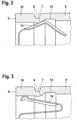
Fig. 2 ein vergrößerter endseitiger Teil einer anderen Variante mit einer zusätzlich von radial innen eingebrachten Nut 13 zwischen Nutwulstvorsprung 7 und bodenseitigem Wandabschnitt 9, teilweise, und im Halbschnitt vergrößert, zur Verdeutlichung der integralen Schnittstellen zwischen Stahlbremskolben 1 und Haltefederschenkel 14 (nur einer von zwei einander diametral gegenüberliegend arrangierten Federschenkeln ist dargestellt), -
Fig. 3 die Variante wie inFig. 2 im Schnitt - jedoch um 90° am Umfang versetzt - zur Verdeutlichung der integralen Schnittstelle zum Radialfederschenkel 15, und -
Fig. 4 der Stahlbremskolben wie inFig. 1 in Ansicht von Links. - Die Erfindung verzichtet auf einen radial einwärts abgewinkelten Randbogen (Kragen) zur Ausbildung einer Hinterschneidung am offenen Ende und verzichtet im Wesentlichen auch auf dessen spanende Nacharbeit. Stattdessen erfolgt ein entfeinerter, fehlertolerant ausgebildeter konstruktiver Aufbau im Zusammenhang mit vergleichsweise grob ausgeführter Umformtoleranz beziehungsweise grob eingestellten Toleranzfeldern, die sich beim Tiefziehprozess einstellen. Mit Hilfe von einer neuartig verbesserten Schnittstellenperipherie wird ein kaltumgeformter, gewichts- und steifigkeitsoptimierter Stahlbremskolben 1 in standardisierter Geometrie vorgelegt, welcher zudem über eine erweiterte Kompatibilität mit unterschiedlich präzise tolerierten Reibbelägen verfügt. Die periphären Freiheitsgrade zwecks Paarung mit unterschiedlich gestalteten oder maßtolerierten Reibbelägen sind folglich erweitert. Das erfindungsgemäße Design erlaubt daher insbesondere eine Variation bzw. Designveränderung betreffend die Federschenkel bzw. Maßvariation in Hinblick auf die Eintauchtiefe von der Belaghaltefeder, beziehungsweise die Dicke einer Rückenplatte 11. Mit anderen Worten ist das erfindungsgemäße Schnittstellendesign so arrangiert, dass in der Kooperation mit den peripheren Bauteilen eine größere Vielfalt, wie insbesondere unterschiedlich weit eingreifende Eintauchtiefen vom Federschenkel 14,15 einer Belaghaltefeder toleriert sind. Demzufolge wird ein kostengünstiger Austauschverbau in Verbindung mit graduell unterschiedlichen, wie insbesondere grob tolerierten, Bauteilen in der Kolbenperipherie erleichtert.
- Ein besonders günstiges Schnittstellendesign wird erreicht, indem eine axiale Projektion vom minimalen Kolbeninnendurchmesser dimin in der Radialrichtung R betrachtet nach radial innen versetzt, außerhalb von der Kolbenstirnfläche 8 platziert, vorgesehen ist.
- Ein besonders rationeller und stabiler Aufbau wird erfindungsgemäß erzielt, indem der Nutwulstvorsprung 7 den minimalen Kolbeninnendurchmesser dimin definiert. Der Nutwulst verbindet zwei rohrförmig-zylindrische, koaxial arrangierte Wandabschnitte 9,10 miteinander, die über einen einheitlichen Außendurchmesser D bei unterschiedlichen Innendurchmessern di, dimax verfügen, so dass diese gewissermaßen zueinander abgestuft vorliegen. Dabei verfügt der endseitig allokierte Wandabschnitt 10 über den kleineren Kolbeninnendurchmesser di im Vergleich mit dem bodenseitig allokierte Wandabschnitt 9 welcher über den maximalen Kolbeninnendurchmesser dimax verfügt. In diesem Kontext ist folgerichtig definiert, dass der bodenseitige Wandabschnitt 9 mit smin über die minimale Wandstärke verfügt im Vergleich zum endseitigen Wandabschnitt 10 mit der der Wandstärke Smax. Die Außendurchmesser der beiden Wandabschnitte 9,10 sind weitestgehend identisch in einer gemeinsamen Flucht vorgesehen. Demzufolge ist die Abfolge der Wandstärken, ausgehend von dem Boden 2, dem folgenden bodenseitigen Wandabschnitt 9, und schließlich dem endseitigen Wandabschnitt 10 mit der Reihenfolge - dick-dünn-dick - ausgestaltet.
- Eine besonders effiziente Werkstoffausnutzung bei günstiger Schnittstellengestaltung ist dadurch gekennzeichnet, dass die besagten Durchmesserunterschiede von den unterschiedlichen Wandabschnitten 9,10 jeweils mindestens etwa 2mm betragen, und wobei die rohrförmig-glatte Länge vom endseitigen Wandabschnitt 10 mindestens etwas 5 mm beträgt.
- In Werkstoffakkumulation, sowie zur weiter verbesserten Kooperation mit Federschenkeln 14,15 am Reibbelag ist es grundsätzlich möglich, dass der bodenseitige Wandabschnitt 9 zusätzlich über eine von radial innen nach radial auswärts gerichtet eingeprägte Nut 13 verfügt, welche mit sichtlich geringem axialem Abstand zu dem Nutwulstvorsprung 7, in Richtung Boden 2 versetzt, vorgesehen ist.
- Die besondere Art und Weise der Kolbenperipheriegestaltung ermöglicht erstmals eine besonders toleranzunempfindliche Aufnahme einer Belaghaltefeder. Durch die besondere Formgebung der Kolbenwandung - insbesondere der Innenwandung 4 - ist eine sichere Schnittstelle mit Aufnahme einer Belaghaltefeder gewährleistet, und zwar innerhalb großräumiger Grenzen und unabhängig davon, wie präzise die Federschenkel 14,15 oder wie dick die Rückenplatte 11 im Einzelnen toleriert ausgeführt ist. Insbesondere ermöglicht die Erfindung einen maximalen Freiheitsgrad in Hinblick auf unterschiedliche Rückenplattengestaltungen wie insbesondere eine Variation der Dicke von einem ggf. verwendeten Dämpfungsblech (Shim) wie auch Anforderungen an die zulässige Flächenpressung wenn die Kolbenstirnfläche 8 auf der Rückenplatte 11 aufsitzt.
- Erfindungsgemäß ist die stirnseitige Kreisringfläche (Kolbenaufstandsfläche) an der offenen Seite des Stahlbremskolbens 1 inetwa mit 30 % von der Kolbenbodenfläche ausgelegt. Unter der Vorgabe vom Nennkolbendurchmesser D folgert daher unmittelbar der auszuwählende Kolbeninnendurchmesser di aus der oben genannten Vorgabe der Flächenverhältnis zwischen Bodenfläche und Kolbenstirnfläche 8. Um eine stets passende axiale Positionierung einer Belaghaltefeder über sämtliche Bremskolbendurchmesservarianten (Baukastensystem) zu ermöglichen, soll ein konstant gehaltener Kolben-Innendurchmesser (d.h. Klemmdurchmesser) di im Klemmbereich der Belaghaltefeder über eine axiale Mindestlänge über eine Länge von mindestens etwa > 5 mm vorliegen. Im Anschluss nach dieser zylindrischen Länge vom Kolbendurchmesser di ist die Hinterschneidung anhand vom Nutwulstvorsprung 7 mit dem nachfolgend maximal definierten Kolbeninnendurchmesser dimax vorgegeben. Dabei ist der Vorsprung quasi parasitär infolge vom Nutwulstvorsprung 7 ausgebildet. Im Anschluss an den Nutwulstvorsprung 7 liegt der bodenseitige Wandabschnitt 9 vor, welcher über den deutlich erweiterten Innendurchmesser dimax verfügt. Dabei beträgt der Durchmesserunterschied mindestens inetwa 2,5 mm.
- Der bodenseitige, erweiterte also größere, und spanlos umgeformt erhaltene Kolben-Innendurchmesser dimax ist im Durchmesser bis zum Übergang in den Kolbenboden 2 weitestgehend konstant, sowie so dimensioniert, dass die notwendige Steifigkeit des Stahlbremskolbens 1 bei gleichzeitig reduzierter Kolbenmasse vorliegt.
- Indem der Nutwulstvorsprung 7 eine Doppelfunktion ((a) kaltverfestigter Versteifungsring b) Wandvorsprung) wahrnimmt, wird eine quasiparasitäre Verklemmung einer Belaghaltefeder am Nutwulstvorsprung 7 ermöglicht. Dies hat den Vorteil, dass auf einen besonderen, kragenförmig abgewinkelten, Randbogen bzw. auf die Fertigung der Nut 13 verzichtet werden kann.
- Ein erfindungsgemäß kaltumgeformter Stahlbremskolben, insbesondere Stahlblechbremskolben 1, ist neben der Außenwandung 5 (Außendurchmesser-Bearbeitung) nur auf seiner Kolbenstirnfläche 8 spanend zu bearbeiten.
- Grundsätzlich wichtige Eckpunkte der Erfindung sind wie folgt:
- 1. Kolbenstirnfläche beträgt nur ca. 30 % von der Kolbenbodenfläche
- 2. Kolbeninnendurchmesser di über einer axial-zylindrisch definierte Länge >5mm.
- 3. Im Kolbeninneren ist am Wandabschnitt 10 ein Hinterschnitt erzeugt, der durch den Nutwulstvorsprung 7 gebildet ist, welcher sich an einen endseitigen Klemmdurchmesser di anschließt. Der Nutwulstvorsprung 7 verbindet den Wandabschnitt 10 mit dem Wandabschnitt 9, welcher im Vergleich zu dem Nutwulstvorsprung 7 über einen deutlich vergrößerten (+ min. 2,5 mm größer) Kolbeninnendurchmesser dimax verfügt.
- 4. Der maximale Kolbeninnendurchmesser dimax ist bei gegebenem Kolbennenndurchmesser D in seiner Wandstärke s genau so stark dimensioniert ausgeführt, wie dies zwingend notwendig ist, damit sich bei noch ausreichender Steifigkeit und Wandstärke s unter Einbezug von Umformgrad und Kaltverfestigung eine gleichzeitig reduzierte Masse vom Stahlbremskolben 1 ergibt. Dabei sind im bodenseitigen Wandungsabschnitt 9 sowohl Innendurchmesser dimax als auch Wandstärke smin im Wesentlichen konstant definiert , bis sich ein allmählicher Übergangsabschnitt mit vergrößerter Wandstärke s im Übergang zum Boden 2 anschließt.
-
- 1 Stahlbremskolben
- 2 Boden
- 3 Wand
- 4 Innenwandung
- 5 Außenwandung
- 6 Nut
- 7 Nutwulstvorsprung
- 8 Kolbenstirnfläche
- 9 Wandabschnitt
- 10 Wandabschnitt
- 11 Rückenplatte
- 12 Scheibenbremse
- 13 Nut
- 14 Federschenkel
- 15 Federschenkel
- A Kolbenlängsachse
- D (Kolben)Nenndurchmesser
- dimin minimaler Innendurchmesser
- dimax maximaler Innendurchmesser
- di Innendurchmesser
- s Kolbenwandstärke
- smin minimale Wandstärke
- smax maximale Wandstärke
- sb Wandstärke vom Boden
- Ax Axialrichtung
- R Radialrichtung
Claims (8)
- Kaltumgeformter Stahlbremskolben (1) für eine hydraulische Scheibenbremse, mit Aufbau als einseitig offener Topf umfassend Boden (2) und Wand (3) einschließlich Innenwandung (4) und Außenwandung (5), mit im Wesentlichen rotationssymmetrisch zur Kolbenlängsachse (A) gerichteter, sowie mit abschnittsweise variierter Wandstärke (s) bei unterschiedlich variiertem Innendurchmesser di, wobei die zur Kolbenlängsachse (A) im Wesentlichen parallel abgestreckt gerichtet geformten Wandabschnitte (9,10) an den orthogonal rechtwinklig zur Kolbenlängsachse (A) ausgeprägten Boden (2) anschließen, und wobei die Außenwandung (5) am endseitigen Wandabschnitt (10) über eine radial einwärts einrollierte Nut (6) verfügt, die nach radial außen offen ist, und radial innen einen Nutwulstvorsprung (7) ausbildet, und wobei die offene Seite vom Topf als Auflager für eine Reibbelagrückenplatte endet, und sich dies Auflager als ebene Kolbenstirnfläche (8) orthogonal-rechtswinklig zu der Kolbenlängsachse (A) erstreckt, sowie mit integrierten Schnittstellen die a) zur Fixierung zwischen Reibbelag und Stahlbremskolben (1) und b) als Stützlager zur Befederung vom Reibbelag dienen, wobei der minimale Kolbeninnendurchmesser (dimin), ausgehend von der Kolbenstirnfläche (8), um ein Mehrfaches der Kolbenwandstärke (s) in Richtung Boden (2) axial rückversetzt verschoben vorliegt, und wobei der minimale Kolbeninnendurchmesser (dimin) vom Nutwulstvorsprung (7) gebildet ist, dadurch gekennzeichnet, dass der endseitige Wandabschnitt (10) über einen kleineren Kolbeninnendurchmesser (di) verfügt als der bodenseitige Wandabschnitt (9), wobei der Nutwulstvorsprung (7) den minimalen Kolbeninnendurchmesser dimin definiert.
- Kaltumgeformter Stahlbremskolben (1) nach Anspruch 1, dadurch gekennzeichnet, dass der in Axialrichtung ax projizierte minimale Kolbeninnendurchmesser (dimin) in Bezug auf die Kolbenstirnfläche (8), sowie bezogen auf die Radialrichtung (R), nach radial innen versetzt, außerhalb von der Kolbenstirnfläche (8) platziert, vorgesehen ist.
- Kaltumgeformter Stahlbremskolben (1) nach Anspruch 1, dadurch gekennzeichnet, dass der Nutwulstvorsprung (7) die zwei unterschiedlich abgestuften, sowie zylindrisch ausgebildeten, Wandabschnitte (9,10) miteinander verbindet.
- Kaltumgeformter Stahlbremskolben (1) nach Anspruch 1, dadurch gekennzeichnet, dass der bodenseitige Wandabschnitt (9) im Vergleich zum endseitigen Wandabschnitt (10) über eine reduzierte Wandstärke (s) verfügt.
- Kaltumgeformter Stahlbremskolben (1) nach Anspruch 1, dadurch gekennzeichnet, dass der Durchmesserunterschied zwischen minimalem Innendurchmesser (dimin) und maximalem Innendurchmesser (dimax) mindestens etwa 2mm betragen.
- Kaltumgeformter Stahlbremskolben (1) nach Anspruch 1, dadurch gekennzeichnet, dass die gestreckte Länge vom endseitigen Wandabschnitt (10) mindestens etwa 5 mm beträgt.
- Kaltumgeformter Stahlbremskolben (1) nach Anspruch 1, dadurch gekennzeichnet, dass der bodenseitige Wandabschnitt (9) über eine radial auswärts gerichtete Nut (13) verfügt, welche mit axialem Abstand zum Nutwulstvorsprung (7) vorgesehen ist.
- Kaltumgeformter Stahlbremskolben (1) nach einem oder mehreren der vorhergehenden Ansprüche, dadurch gekennzeichnet, dass ein besonders definiertes Kolbenwandstärkenverhältnis, nämlich ein Quotient der Wandstärke sb vom Boden (2) bezogen auf eine minimale Kolbenwandstärke smin vom bodenseitigen Wandabschnitt (9), also sb/smin, mit 1,4 - 2,1 vorgesehen ist.
Applications Claiming Priority (2)
| Application Number | Priority Date | Filing Date | Title |
|---|---|---|---|
| DE102016210817 | 2016-06-16 | ||
| PCT/EP2017/060109 WO2017215826A1 (de) | 2016-06-16 | 2017-04-27 | Stahlbremskolben für eine hydraulische bremse |
Publications (2)
| Publication Number | Publication Date |
|---|---|
| EP3471914A1 EP3471914A1 (de) | 2019-04-24 |
| EP3471914B1 true EP3471914B1 (de) | 2023-09-13 |
Family
ID=58633011
Family Applications (1)
| Application Number | Title | Priority Date | Filing Date |
|---|---|---|---|
| EP17719620.1A Active EP3471914B1 (de) | 2016-06-16 | 2017-04-27 | Stahlblechbremskolben fur eine hydraulische bremse |
Country Status (7)
| Country | Link |
|---|---|
| US (1) | US11236826B2 (de) |
| EP (1) | EP3471914B1 (de) |
| JP (1) | JP6670402B2 (de) |
| KR (1) | KR102233527B1 (de) |
| CN (1) | CN109562496B (de) |
| DE (1) | DE102017207140A1 (de) |
| WO (1) | WO2017215826A1 (de) |
Families Citing this family (1)
| Publication number | Priority date | Publication date | Assignee | Title |
|---|---|---|---|---|
| US11585397B2 (en) * | 2020-11-30 | 2023-02-21 | Honeywell International Inc. | Piston cap |
Citations (1)
| Publication number | Priority date | Publication date | Assignee | Title |
|---|---|---|---|---|
| US4193179A (en) * | 1977-11-14 | 1980-03-18 | Condor Manufacturing Inc. | Process of manufacturing an article having a groove rolled therein, and an article produced thereby |
Family Cites Families (17)
| Publication number | Priority date | Publication date | Assignee | Title |
|---|---|---|---|---|
| GB1169251A (en) * | 1967-05-22 | 1969-11-05 | Girling Ltd | Improvements relating to pistons |
| JPS5690130A (en) | 1980-12-03 | 1981-07-22 | Akebono Brake Ind Co Ltd | Forged piston for disc brake |
| DE4003731A1 (de) | 1990-02-08 | 1991-08-14 | Teves Gmbh Alfred | Kaltverformter kolben fuer hydraulisch arbeitende bremse |
| US5105917A (en) * | 1990-12-31 | 1992-04-21 | Kelsey-Hayes Company | Disc brake piston |
| DE4340453A1 (de) | 1993-11-27 | 1995-06-01 | Teves Gmbh Alfred | Bremskolben für Scheibenbremsen |
| DE19603586A1 (de) | 1996-02-01 | 1997-08-07 | Teves Gmbh Alfred | Kaltgeformter Kolben für eine hydraulische Bremse |
| DE29815358U1 (de) * | 1998-08-27 | 1999-04-08 | ITT Mfg. Enterprises, Inc., Wilmington, Del. | Kaltverformter Kolben für eine hydraulische Bremse |
| WO2001002745A1 (de) * | 1999-07-02 | 2001-01-11 | Continental Teves Ag & Co. Ohg | Kolben für einen hydraulischen druckraum |
| RU2163987C1 (ru) * | 2000-04-12 | 2001-03-10 | Общество с ограниченной ответственностью "Синхрон-Рус" | Поршень дискового тормоза, изготовленный вытяжкой |
| RU2189510C1 (ru) * | 2001-08-08 | 2002-09-20 | Общество с ограниченной ответственностью "Синхрон-Рус" | Поршень гидравлического цилиндра, изготовленный из листового металла |
| DE102005061354A1 (de) * | 2005-12-21 | 2007-06-28 | Continental Teves Ag & Co. Ohg | Kolben für eine hydraulische Bremse und Verfahren zur Herstellung |
| JP2007232064A (ja) * | 2006-02-28 | 2007-09-13 | Akebono Brake Ind Co Ltd | 有底円筒ピストンの防塵ブーツ用溝成形方法及び該成形方法によって作られるピストン |
| DE102007051456A1 (de) | 2007-10-27 | 2009-04-30 | Continental Teves Ag & Co. Ohg | Kolben für einen Bremssattel einer Bremsscheibe |
| DE102009017167A1 (de) * | 2008-06-17 | 2009-12-24 | Continental Teves Ag & Co. Ohg | Mehrteilig gebauter Kolben für einen Bremssattel einer Scheibenbremse |
| DE102012203162A1 (de) | 2011-09-06 | 2013-03-07 | Continental Teves Ag & Co. Ohg | Kolben für einen Bremssattel einer Scheibenbremse |
| CN203248580U (zh) * | 2013-05-20 | 2013-10-23 | 丹阳市可达汽车配件有限公司 | 一种制动钳活塞 |
| CN106660105B (zh) | 2014-07-31 | 2019-09-13 | 日立汽车系统株式会社 | 活塞制造装置、活塞制造方法、活塞及盘式制动器 |
-
2017
- 2017-04-27 EP EP17719620.1A patent/EP3471914B1/de active Active
- 2017-04-27 JP JP2018563592A patent/JP6670402B2/ja not_active Expired - Fee Related
- 2017-04-27 US US16/300,181 patent/US11236826B2/en active Active
- 2017-04-27 WO PCT/EP2017/060109 patent/WO2017215826A1/de not_active Ceased
- 2017-04-27 CN CN201780036568.0A patent/CN109562496B/zh active Active
- 2017-04-27 KR KR1020187037388A patent/KR102233527B1/ko not_active Expired - Fee Related
- 2017-04-27 DE DE102017207140.0A patent/DE102017207140A1/de not_active Withdrawn
Patent Citations (1)
| Publication number | Priority date | Publication date | Assignee | Title |
|---|---|---|---|---|
| US4193179A (en) * | 1977-11-14 | 1980-03-18 | Condor Manufacturing Inc. | Process of manufacturing an article having a groove rolled therein, and an article produced thereby |
Also Published As
| Publication number | Publication date |
|---|---|
| US11236826B2 (en) | 2022-02-01 |
| WO2017215826A1 (de) | 2017-12-21 |
| US20190178379A1 (en) | 2019-06-13 |
| JP6670402B2 (ja) | 2020-03-18 |
| KR102233527B1 (ko) | 2021-03-30 |
| CN109562496A (zh) | 2019-04-02 |
| JP2019518913A (ja) | 2019-07-04 |
| CN109562496B (zh) | 2021-03-16 |
| BR112018075940A2 (pt) | 2019-05-07 |
| KR20190012196A (ko) | 2019-02-08 |
| DE102017207140A1 (de) | 2017-12-21 |
| EP3471914A1 (de) | 2019-04-24 |
Similar Documents
| Publication | Publication Date | Title |
|---|---|---|
| DE10333879A1 (de) | Planetenträger für Getriebe | |
| EP1704339B1 (de) | Aussenring eines radlagers und axiale sicherung des aussenringes | |
| EP3347612A1 (de) | Druckstück eines fahrzeuggetriebes und synchronisiereinheit | |
| DE102011015836A1 (de) | Blech-Synchronring sowie Verfahren zur Herstellung eines Blech-Synchronrings | |
| EP2341029A2 (de) | Hebezeug mit einer Twistlock-Baugruppe | |
| EP2265834B1 (de) | Käfig für ein wälzlager | |
| AT514033B1 (de) | Verfahren zum Herstellen eines Laufs mit einstückig anschließendem Gehäuse | |
| DE10359645B4 (de) | Radlagermodul in einem Radträger | |
| WO2000063572A1 (de) | Gebauter synchronkörper mit anschlagelement | |
| EP3110587A1 (de) | Lötspitzenbefestigungssystem | |
| EP3695134B1 (de) | Kaltumgeformter stahlbremskolben für eine kraftfahrzeugteilbelagscheibenbremse | |
| DE102013216039A1 (de) | Halbhohlstanzniet für das vorlochfreie Fügen eines FVK-Bauteils mit einem Metallbauteil | |
| DE102007023972A1 (de) | Verfahren zur Herstellung einer Nabe im Drückverfahren mittels wenigstens einer drehbaren Drückrolle | |
| EP0877871B1 (de) | Kaltverformter kolben für eine hydraulische bremse | |
| DE102017207140A1 (de) | Stahlbremskolben für eine hydraulische Bremse und Verfahren zur Herstellung | |
| EP1694974A1 (de) | Radlager in einem radträger | |
| DE102015219855A1 (de) | Hohlrad mit Innenverzahnung und Kronenverzahnung, sowie Verfahren zu dessen Herstellung und Schaltgetriebe mit solchem Hohlrad | |
| DE19912130B4 (de) | Gebaute Schiebemuffe einer Synchronisiereinheit für Schaltgetriebe | |
| WO2019015710A1 (de) | Gewindemutter für einen kugelgewindetrieb | |
| WO2018166547A1 (de) | Spindelmutter für einen kugelgewindetrieb und verfahren zur herstellung einer spindelmutter | |
| DE102017219160A1 (de) | Schraube zum Einschrauben in ein Bohrloch | |
| EP2406526B1 (de) | Planetenträger aus blech und planetenradeinheit mit mindestens einem planetenträger aus blech | |
| EP3173184B1 (de) | Verfahren zur herstellung eines doppelkonus-synchronrings | |
| DE102006061415A1 (de) | Synchronring einer Synchronisiereinrichtung | |
| DE102018119490A1 (de) | Planetenträger für Planetengetriebe mit formschlussausbildenden Planetenträgerverbindungsbolzen |
Legal Events
| Date | Code | Title | Description |
|---|---|---|---|
| STAA | Information on the status of an ep patent application or granted ep patent |
Free format text: STATUS: UNKNOWN |
|
| STAA | Information on the status of an ep patent application or granted ep patent |
Free format text: STATUS: THE INTERNATIONAL PUBLICATION HAS BEEN MADE |
|
| PUAI | Public reference made under article 153(3) epc to a published international application that has entered the european phase |
Free format text: ORIGINAL CODE: 0009012 |
|
| STAA | Information on the status of an ep patent application or granted ep patent |
Free format text: STATUS: REQUEST FOR EXAMINATION WAS MADE |
|
| 17P | Request for examination filed |
Effective date: 20190116 |
|
| AK | Designated contracting states |
Kind code of ref document: A1 Designated state(s): AL AT BE BG CH CY CZ DE DK EE ES FI FR GB GR HR HU IE IS IT LI LT LU LV MC MK MT NL NO PL PT RO RS SE SI SK SM TR |
|
| AX | Request for extension of the european patent |
Extension state: BA ME |
|
| DAV | Request for validation of the european patent (deleted) | ||
| DAX | Request for extension of the european patent (deleted) | ||
| STAA | Information on the status of an ep patent application or granted ep patent |
Free format text: STATUS: EXAMINATION IS IN PROGRESS |
|
| 17Q | First examination report despatched |
Effective date: 20191122 |
|
| GRAP | Despatch of communication of intention to grant a patent |
Free format text: ORIGINAL CODE: EPIDOSNIGR1 |
|
| STAA | Information on the status of an ep patent application or granted ep patent |
Free format text: STATUS: GRANT OF PATENT IS INTENDED |
|
| INTG | Intention to grant announced |
Effective date: 20230417 |
|
| RAP1 | Party data changed (applicant data changed or rights of an application transferred) |
Owner name: ERDRICH UMFORMTECHNIK GMBH Owner name: CONTINENTAL AUTOMOTIVE TECHNOLOGIES GMBH |
|
| GRAS | Grant fee paid |
Free format text: ORIGINAL CODE: EPIDOSNIGR3 |
|
| GRAA | (expected) grant |
Free format text: ORIGINAL CODE: 0009210 |
|
| STAA | Information on the status of an ep patent application or granted ep patent |
Free format text: STATUS: THE PATENT HAS BEEN GRANTED |
|
| AK | Designated contracting states |
Kind code of ref document: B1 Designated state(s): AL AT BE BG CH CY CZ DE DK EE ES FI FR GB GR HR HU IE IS IT LI LT LU LV MC MK MT NL NO PL PT RO RS SE SI SK SM TR |
|
| REG | Reference to a national code |
Ref country code: GB Ref legal event code: FG4D Free format text: NOT ENGLISH |
|
| REG | Reference to a national code |
Ref country code: CH Ref legal event code: EP |
|
| REG | Reference to a national code |
Ref country code: DE Ref legal event code: R096 Ref document number: 502017015373 Country of ref document: DE |
|
| REG | Reference to a national code |
Ref country code: IE Ref legal event code: FG4D Free format text: LANGUAGE OF EP DOCUMENT: GERMAN |
|
| REG | Reference to a national code |
Ref country code: LT Ref legal event code: MG9D |
|
| REG | Reference to a national code |
Ref country code: NL Ref legal event code: MP Effective date: 20230913 |
|
| PG25 | Lapsed in a contracting state [announced via postgrant information from national office to epo] |
Ref country code: GR Free format text: LAPSE BECAUSE OF FAILURE TO SUBMIT A TRANSLATION OF THE DESCRIPTION OR TO PAY THE FEE WITHIN THE PRESCRIBED TIME-LIMIT Effective date: 20231214 |
|
| PG25 | Lapsed in a contracting state [announced via postgrant information from national office to epo] |
Ref country code: SE Free format text: LAPSE BECAUSE OF FAILURE TO SUBMIT A TRANSLATION OF THE DESCRIPTION OR TO PAY THE FEE WITHIN THE PRESCRIBED TIME-LIMIT Effective date: 20230913 Ref country code: RS Free format text: LAPSE BECAUSE OF FAILURE TO SUBMIT A TRANSLATION OF THE DESCRIPTION OR TO PAY THE FEE WITHIN THE PRESCRIBED TIME-LIMIT Effective date: 20230913 Ref country code: NO Free format text: LAPSE BECAUSE OF FAILURE TO SUBMIT A TRANSLATION OF THE DESCRIPTION OR TO PAY THE FEE WITHIN THE PRESCRIBED TIME-LIMIT Effective date: 20231213 Ref country code: LV Free format text: LAPSE BECAUSE OF FAILURE TO SUBMIT A TRANSLATION OF THE DESCRIPTION OR TO PAY THE FEE WITHIN THE PRESCRIBED TIME-LIMIT Effective date: 20230913 Ref country code: LT Free format text: LAPSE BECAUSE OF FAILURE TO SUBMIT A TRANSLATION OF THE DESCRIPTION OR TO PAY THE FEE WITHIN THE PRESCRIBED TIME-LIMIT Effective date: 20230913 Ref country code: HR Free format text: LAPSE BECAUSE OF FAILURE TO SUBMIT A TRANSLATION OF THE DESCRIPTION OR TO PAY THE FEE WITHIN THE PRESCRIBED TIME-LIMIT Effective date: 20230913 Ref country code: GR Free format text: LAPSE BECAUSE OF FAILURE TO SUBMIT A TRANSLATION OF THE DESCRIPTION OR TO PAY THE FEE WITHIN THE PRESCRIBED TIME-LIMIT Effective date: 20231214 Ref country code: FI Free format text: LAPSE BECAUSE OF FAILURE TO SUBMIT A TRANSLATION OF THE DESCRIPTION OR TO PAY THE FEE WITHIN THE PRESCRIBED TIME-LIMIT Effective date: 20230913 |
|
| REG | Reference to a national code |
Ref country code: DE Ref legal event code: R081 Ref document number: 502017015373 Country of ref document: DE Owner name: ERDRICH UMFORMTECHNIK GMBH, DE Free format text: FORMER OWNERS: CONTINENTAL AUTOMOTIVE TECHNOLOGIES GMBH, 30165 HANNOVER, DE; ERDRICH UMFORMTECHNIK GMBH, 77871 RENCHEN, DE Ref country code: DE Ref legal event code: R081 Ref document number: 502017015373 Country of ref document: DE Owner name: CONTINENTAL AUTOMOTIVE TECHNOLOGIES GMBH, DE Free format text: FORMER OWNERS: CONTINENTAL AUTOMOTIVE TECHNOLOGIES GMBH, 30165 HANNOVER, DE; ERDRICH UMFORMTECHNIK GMBH, 77871 RENCHEN, DE Ref country code: DE Ref legal event code: R081 Ref document number: 502017015373 Country of ref document: DE Owner name: AUMOVIO GERMANY GMBH, DE Free format text: FORMER OWNERS: CONTINENTAL AUTOMOTIVE TECHNOLOGIES GMBH, 30165 HANNOVER, DE; ERDRICH UMFORMTECHNIK GMBH, 77871 RENCHEN, DE |
|
| PG25 | Lapsed in a contracting state [announced via postgrant information from national office to epo] |
Ref country code: NL Free format text: LAPSE BECAUSE OF FAILURE TO SUBMIT A TRANSLATION OF THE DESCRIPTION OR TO PAY THE FEE WITHIN THE PRESCRIBED TIME-LIMIT Effective date: 20230913 |
|
| PG25 | Lapsed in a contracting state [announced via postgrant information from national office to epo] |
Ref country code: IS Free format text: LAPSE BECAUSE OF FAILURE TO SUBMIT A TRANSLATION OF THE DESCRIPTION OR TO PAY THE FEE WITHIN THE PRESCRIBED TIME-LIMIT Effective date: 20240113 |
|
| RAP4 | Party data changed (patent owner data changed or rights of a patent transferred) |
Owner name: ERDRICH UMFORMTECHNIK GMBH Owner name: CONTINENTAL AUTOMOTIVE TECHNOLOGIES GMBH |
|
| PG25 | Lapsed in a contracting state [announced via postgrant information from national office to epo] |
Ref country code: ES Free format text: LAPSE BECAUSE OF FAILURE TO SUBMIT A TRANSLATION OF THE DESCRIPTION OR TO PAY THE FEE WITHIN THE PRESCRIBED TIME-LIMIT Effective date: 20230913 |
|
| PG25 | Lapsed in a contracting state [announced via postgrant information from national office to epo] |
Ref country code: SM Free format text: LAPSE BECAUSE OF FAILURE TO SUBMIT A TRANSLATION OF THE DESCRIPTION OR TO PAY THE FEE WITHIN THE PRESCRIBED TIME-LIMIT Effective date: 20230913 Ref country code: RO Free format text: LAPSE BECAUSE OF FAILURE TO SUBMIT A TRANSLATION OF THE DESCRIPTION OR TO PAY THE FEE WITHIN THE PRESCRIBED TIME-LIMIT Effective date: 20230913 Ref country code: IS Free format text: LAPSE BECAUSE OF FAILURE TO SUBMIT A TRANSLATION OF THE DESCRIPTION OR TO PAY THE FEE WITHIN THE PRESCRIBED TIME-LIMIT Effective date: 20240113 Ref country code: ES Free format text: LAPSE BECAUSE OF FAILURE TO SUBMIT A TRANSLATION OF THE DESCRIPTION OR TO PAY THE FEE WITHIN THE PRESCRIBED TIME-LIMIT Effective date: 20230913 Ref country code: EE Free format text: LAPSE BECAUSE OF FAILURE TO SUBMIT A TRANSLATION OF THE DESCRIPTION OR TO PAY THE FEE WITHIN THE PRESCRIBED TIME-LIMIT Effective date: 20230913 Ref country code: CZ Free format text: LAPSE BECAUSE OF FAILURE TO SUBMIT A TRANSLATION OF THE DESCRIPTION OR TO PAY THE FEE WITHIN THE PRESCRIBED TIME-LIMIT Effective date: 20230913 Ref country code: SK Free format text: LAPSE BECAUSE OF FAILURE TO SUBMIT A TRANSLATION OF THE DESCRIPTION OR TO PAY THE FEE WITHIN THE PRESCRIBED TIME-LIMIT Effective date: 20230913 Ref country code: PT Free format text: LAPSE BECAUSE OF FAILURE TO SUBMIT A TRANSLATION OF THE DESCRIPTION OR TO PAY THE FEE WITHIN THE PRESCRIBED TIME-LIMIT Effective date: 20240115 |
|
| REG | Reference to a national code |
Ref country code: CH Ref legal event code: PK Free format text: DIE PUBLIKATION VOM 27.03.2024 WURDE AM 24.04.2024 IRRTUEMLICHERWEISE ERNEUT PUBLIZIERT. LA PUBLICATION DU 27.03.2024 A ETE REPUBLIEE PAR ERREUR LE 24.04.2024. LA PUBBLICAZIONE DEL 27.03.2024 E STATA ERRONEAMENTE RIPUBBLICATA IL 24.04.2024. |
|
| PG25 | Lapsed in a contracting state [announced via postgrant information from national office to epo] |
Ref country code: PL Free format text: LAPSE BECAUSE OF FAILURE TO SUBMIT A TRANSLATION OF THE DESCRIPTION OR TO PAY THE FEE WITHIN THE PRESCRIBED TIME-LIMIT Effective date: 20230913 Ref country code: IT Free format text: LAPSE BECAUSE OF FAILURE TO SUBMIT A TRANSLATION OF THE DESCRIPTION OR TO PAY THE FEE WITHIN THE PRESCRIBED TIME-LIMIT Effective date: 20230913 |
|
| REG | Reference to a national code |
Ref country code: DE Ref legal event code: R097 Ref document number: 502017015373 Country of ref document: DE |
|
| PG25 | Lapsed in a contracting state [announced via postgrant information from national office to epo] |
Ref country code: DK Free format text: LAPSE BECAUSE OF FAILURE TO SUBMIT A TRANSLATION OF THE DESCRIPTION OR TO PAY THE FEE WITHIN THE PRESCRIBED TIME-LIMIT Effective date: 20230913 |
|
| PLBE | No opposition filed within time limit |
Free format text: ORIGINAL CODE: 0009261 |
|
| STAA | Information on the status of an ep patent application or granted ep patent |
Free format text: STATUS: NO OPPOSITION FILED WITHIN TIME LIMIT |
|
| PG25 | Lapsed in a contracting state [announced via postgrant information from national office to epo] |
Ref country code: DK Free format text: LAPSE BECAUSE OF FAILURE TO SUBMIT A TRANSLATION OF THE DESCRIPTION OR TO PAY THE FEE WITHIN THE PRESCRIBED TIME-LIMIT Effective date: 20230913 |
|
| 26N | No opposition filed |
Effective date: 20240614 |
|
| PG25 | Lapsed in a contracting state [announced via postgrant information from national office to epo] |
Ref country code: SI Free format text: LAPSE BECAUSE OF FAILURE TO SUBMIT A TRANSLATION OF THE DESCRIPTION OR TO PAY THE FEE WITHIN THE PRESCRIBED TIME-LIMIT Effective date: 20230913 |
|
| PG25 | Lapsed in a contracting state [announced via postgrant information from national office to epo] |
Ref country code: SI Free format text: LAPSE BECAUSE OF FAILURE TO SUBMIT A TRANSLATION OF THE DESCRIPTION OR TO PAY THE FEE WITHIN THE PRESCRIBED TIME-LIMIT Effective date: 20230913 |
|
| PG25 | Lapsed in a contracting state [announced via postgrant information from national office to epo] |
Ref country code: BG Free format text: LAPSE BECAUSE OF FAILURE TO SUBMIT A TRANSLATION OF THE DESCRIPTION OR TO PAY THE FEE WITHIN THE PRESCRIBED TIME-LIMIT Effective date: 20230913 |
|
| PG25 | Lapsed in a contracting state [announced via postgrant information from national office to epo] |
Ref country code: MC Free format text: LAPSE BECAUSE OF FAILURE TO SUBMIT A TRANSLATION OF THE DESCRIPTION OR TO PAY THE FEE WITHIN THE PRESCRIBED TIME-LIMIT Effective date: 20230913 |
|
| PG25 | Lapsed in a contracting state [announced via postgrant information from national office to epo] |
Ref country code: MC Free format text: LAPSE BECAUSE OF FAILURE TO SUBMIT A TRANSLATION OF THE DESCRIPTION OR TO PAY THE FEE WITHIN THE PRESCRIBED TIME-LIMIT Effective date: 20230913 Ref country code: BG Free format text: LAPSE BECAUSE OF FAILURE TO SUBMIT A TRANSLATION OF THE DESCRIPTION OR TO PAY THE FEE WITHIN THE PRESCRIBED TIME-LIMIT Effective date: 20230913 |
|
| REG | Reference to a national code |
Ref country code: CH Ref legal event code: PL |
|
| PG25 | Lapsed in a contracting state [announced via postgrant information from national office to epo] |
Ref country code: LU Free format text: LAPSE BECAUSE OF NON-PAYMENT OF DUE FEES Effective date: 20240427 |
|
| GBPC | Gb: european patent ceased through non-payment of renewal fee |
Effective date: 20240427 |
|
| REG | Reference to a national code |
Ref country code: BE Ref legal event code: MM Effective date: 20240430 |
|
| PG25 | Lapsed in a contracting state [announced via postgrant information from national office to epo] |
Ref country code: LU Free format text: LAPSE BECAUSE OF NON-PAYMENT OF DUE FEES Effective date: 20240427 |
|
| PG25 | Lapsed in a contracting state [announced via postgrant information from national office to epo] |
Ref country code: BE Free format text: LAPSE BECAUSE OF NON-PAYMENT OF DUE FEES Effective date: 20240430 |
|
| PG25 | Lapsed in a contracting state [announced via postgrant information from national office to epo] |
Ref country code: GB Free format text: LAPSE BECAUSE OF NON-PAYMENT OF DUE FEES Effective date: 20240427 |
|
| PG25 | Lapsed in a contracting state [announced via postgrant information from national office to epo] |
Ref country code: FR Free format text: LAPSE BECAUSE OF NON-PAYMENT OF DUE FEES Effective date: 20240430 |
|
| PG25 | Lapsed in a contracting state [announced via postgrant information from national office to epo] |
Ref country code: GB Free format text: LAPSE BECAUSE OF NON-PAYMENT OF DUE FEES Effective date: 20240427 Ref country code: FR Free format text: LAPSE BECAUSE OF NON-PAYMENT OF DUE FEES Effective date: 20240430 Ref country code: BE Free format text: LAPSE BECAUSE OF NON-PAYMENT OF DUE FEES Effective date: 20240430 Ref country code: CH Free format text: LAPSE BECAUSE OF NON-PAYMENT OF DUE FEES Effective date: 20240430 |
|
| PG25 | Lapsed in a contracting state [announced via postgrant information from national office to epo] |
Ref country code: IE Free format text: LAPSE BECAUSE OF NON-PAYMENT OF DUE FEES Effective date: 20240427 |
|
| REG | Reference to a national code |
Ref country code: AT Ref legal event code: MM01 Ref document number: 1610780 Country of ref document: AT Kind code of ref document: T Effective date: 20240427 |
|
| PGFP | Annual fee paid to national office [announced via postgrant information from national office to epo] |
Ref country code: DE Payment date: 20250430 Year of fee payment: 9 |
|
| PG25 | Lapsed in a contracting state [announced via postgrant information from national office to epo] |
Ref country code: AT Free format text: LAPSE BECAUSE OF NON-PAYMENT OF DUE FEES Effective date: 20240427 |
|
| PG25 | Lapsed in a contracting state [announced via postgrant information from national office to epo] |
Ref country code: CY Free format text: LAPSE BECAUSE OF FAILURE TO SUBMIT A TRANSLATION OF THE DESCRIPTION OR TO PAY THE FEE WITHIN THE PRESCRIBED TIME-LIMIT; INVALID AB INITIO Effective date: 20170427 |
|
| PG25 | Lapsed in a contracting state [announced via postgrant information from national office to epo] |
Ref country code: HU Free format text: LAPSE BECAUSE OF FAILURE TO SUBMIT A TRANSLATION OF THE DESCRIPTION OR TO PAY THE FEE WITHIN THE PRESCRIBED TIME-LIMIT; INVALID AB INITIO Effective date: 20170427 |
|
| REG | Reference to a national code |
Ref country code: DE Ref legal event code: R081 Ref document number: 502017015373 Country of ref document: DE Owner name: AUMOVIO GERMANY GMBH, DE Free format text: FORMER OWNERS: CONTINENTAL AUTOMOTIVE TECHNOLOGIES GMBH, 30175 HANNOVER, DE; ERDRICH UMFORMTECHNIK GMBH, 77871 RENCHEN, DE Ref country code: DE Ref legal event code: R081 Ref document number: 502017015373 Country of ref document: DE Owner name: ERDRICH UMFORMTECHNIK GMBH, DE Free format text: FORMER OWNERS: CONTINENTAL AUTOMOTIVE TECHNOLOGIES GMBH, 30175 HANNOVER, DE; ERDRICH UMFORMTECHNIK GMBH, 77871 RENCHEN, DE |