EP3471241A1 - Rotor and motor including same - Google Patents
Rotor and motor including same Download PDFInfo
- Publication number
- EP3471241A1 EP3471241A1 EP17813553.9A EP17813553A EP3471241A1 EP 3471241 A1 EP3471241 A1 EP 3471241A1 EP 17813553 A EP17813553 A EP 17813553A EP 3471241 A1 EP3471241 A1 EP 3471241A1
- Authority
- EP
- European Patent Office
- Prior art keywords
- rotor
- cover
- rotor core
- combined
- magnet
- Prior art date
- Legal status (The legal status is an assumption and is not a legal conclusion. Google has not performed a legal analysis and makes no representation as to the accuracy of the status listed.)
- Granted
Links
- 239000000853 adhesive Substances 0.000 abstract description 7
- 230000001070 adhesive effect Effects 0.000 abstract description 7
- 230000000694 effects Effects 0.000 abstract description 4
- 230000008878 coupling Effects 0.000 abstract 1
- 238000010168 coupling process Methods 0.000 abstract 1
- 238000005859 coupling reaction Methods 0.000 abstract 1
- 238000000034 method Methods 0.000 description 4
- 230000003993 interaction Effects 0.000 description 3
- 229910000831 Steel Inorganic materials 0.000 description 2
- 239000010959 steel Substances 0.000 description 2
- VLLVVZDKBSYMCG-UHFFFAOYSA-N 1,3,5-trichloro-2-(2-chlorophenyl)benzene Chemical compound ClC1=CC(Cl)=CC(Cl)=C1C1=CC=CC=C1Cl VLLVVZDKBSYMCG-UHFFFAOYSA-N 0.000 description 1
- XAGFODPZIPBFFR-UHFFFAOYSA-N aluminium Chemical compound [Al] XAGFODPZIPBFFR-UHFFFAOYSA-N 0.000 description 1
- 229910052782 aluminium Inorganic materials 0.000 description 1
- 239000012212 insulator Substances 0.000 description 1
- 238000004519 manufacturing process Methods 0.000 description 1
- 239000000463 material Substances 0.000 description 1
- 238000012986 modification Methods 0.000 description 1
- 230000004048 modification Effects 0.000 description 1
- 238000000465 moulding Methods 0.000 description 1
- 230000001012 protector Effects 0.000 description 1
- 238000000926 separation method Methods 0.000 description 1
Images


Classifications
-
- H—ELECTRICITY
- H02—GENERATION; CONVERSION OR DISTRIBUTION OF ELECTRIC POWER
- H02K—DYNAMO-ELECTRIC MACHINES
- H02K1/00—Details of the magnetic circuit
- H02K1/06—Details of the magnetic circuit characterised by the shape, form or construction
- H02K1/22—Rotating parts of the magnetic circuit
- H02K1/27—Rotor cores with permanent magnets
- H02K1/2706—Inner rotors
- H02K1/272—Inner rotors the magnetisation axis of the magnets being perpendicular to the rotor axis
- H02K1/274—Inner rotors the magnetisation axis of the magnets being perpendicular to the rotor axis the rotor consisting of two or more circumferentially positioned magnets
- H02K1/2753—Inner rotors the magnetisation axis of the magnets being perpendicular to the rotor axis the rotor consisting of two or more circumferentially positioned magnets the rotor consisting of magnets or groups of magnets arranged with alternating polarity
- H02K1/278—Surface mounted magnets; Inset magnets
-
- B—PERFORMING OPERATIONS; TRANSPORTING
- B62—LAND VEHICLES FOR TRAVELLING OTHERWISE THAN ON RAILS
- B62D—MOTOR VEHICLES; TRAILERS
- B62D5/00—Power-assisted or power-driven steering
- B62D5/04—Power-assisted or power-driven steering electrical, e.g. using an electric servo-motor connected to, or forming part of, the steering gear
- B62D5/0403—Power-assisted or power-driven steering electrical, e.g. using an electric servo-motor connected to, or forming part of, the steering gear characterised by constructional features, e.g. common housing for motor and gear box
-
- B—PERFORMING OPERATIONS; TRANSPORTING
- B62—LAND VEHICLES FOR TRAVELLING OTHERWISE THAN ON RAILS
- B62D—MOTOR VEHICLES; TRAILERS
- B62D5/00—Power-assisted or power-driven steering
- B62D5/04—Power-assisted or power-driven steering electrical, e.g. using an electric servo-motor connected to, or forming part of, the steering gear
-
- H—ELECTRICITY
- H02—GENERATION; CONVERSION OR DISTRIBUTION OF ELECTRIC POWER
- H02K—DYNAMO-ELECTRIC MACHINES
- H02K1/00—Details of the magnetic circuit
- H02K1/06—Details of the magnetic circuit characterised by the shape, form or construction
- H02K1/22—Rotating parts of the magnetic circuit
- H02K1/28—Means for mounting or fastening rotating magnetic parts on to, or to, the rotor structures
-
- H—ELECTRICITY
- H02—GENERATION; CONVERSION OR DISTRIBUTION OF ELECTRIC POWER
- H02K—DYNAMO-ELECTRIC MACHINES
- H02K21/00—Synchronous motors having permanent magnets; Synchronous generators having permanent magnets
- H02K21/12—Synchronous motors having permanent magnets; Synchronous generators having permanent magnets with stationary armatures and rotating magnets
- H02K21/14—Synchronous motors having permanent magnets; Synchronous generators having permanent magnets with stationary armatures and rotating magnets with magnets rotating within the armatures
-
- H—ELECTRICITY
- H02—GENERATION; CONVERSION OR DISTRIBUTION OF ELECTRIC POWER
- H02K—DYNAMO-ELECTRIC MACHINES
- H02K2213/00—Specific aspects, not otherwise provided for and not covered by codes H02K2201/00 - H02K2211/00
- H02K2213/03—Machines characterised by numerical values, ranges, mathematical expressions or similar information
Definitions
- Embodiments relate to a rotor and a motor including the same.
- An electric power steering (EPS) system is an apparatus capable of allowing a driver to safely drive a vehicle by securing circling stability of the vehicle and providing a quick restoring force.
- the EPS system controls driving of a steering shaft of the vehicle by driving a motor through an electronic control unit (ECU) according to driving conditions sensed by a vehicle speed sensor, a torque angle sensor, a torque sensor, and the like.
- ECU electronice control unit
- a rotor of the motor of the EPS system may include a magnet.
- the magnet may be attached to an outer circumferential surface of a rotor core.
- a variety of types of protectors are applied to improve durability of assembled magnets.
- a can type is the most commonly applied method and protects the rotor and prevents separation of the magnets by combining cup-shaped cans with a top and a bottom of an outer circumferential surface of the rotor.
- an adhesive is applied to an inside of the can.
- a process of applying the adhesive has a problem of complicating a process of assembling the rotor.
- uniformly applying a fixed quantity of the adhesive to a bonding part between the can and the rotor is very complicated.
- two cans are used such that the number of components increases and manufacturing costs increase.
- the present invention is directed to providing a rotor capable of excluding use of an adhesive and reducing the number of cans and a motor including the same.
- a rotor including a rotor core, a cover disposed above the rotor core, a magnet disposed on an outer circumferential surface of the rotor core, and a can member which accommodates the rotor core and the magnet and is combined with the cover.
- the can member includes at least one protrusion portion which protrudes from an edge and is combined with the cover.
- the can member may include a cylindrical body which surrounds the magnet, and the protrusion portion may be formed on any one side of the body.
- the rotor may include a flange portion which is formed on the other side of the body and internally faces a center of the can member.
- the protrusion portion may be located in a center of the magnet on the basis of a circumferential direction of the rotor core.
- the number of such protrusion portions may be equal to the number of the magnets.
- the cover may include a cover body including an annular inner portion and an outer portion formed outside the inner portion, and the outer portion may be formed to be higher than the inner portion on the basis of an axial direction of the rotor core.
- the protrusion portion may be combined with the outer portion.
- the outer portion may include an inclined surface formed to be inclined toward a center of the rotor core.
- the outer portion may include an engaging groove portion which is formed to be concave and with which the protrusion portion is combined.
- the cover may include a stopper including a protruding column portion and a fixing portion extending from the column portion, and the fixing portion may be disposed above the protrusion portion combined with the cover in a radial direction from a center of the rotor core.
- the column portion may protrude from a top surface of the inner portion, and a fore end of the fixing portion may be located farther out than a fore end of the protrusion portion combined with the cover in the radial direction from the center of the rotor core.
- a bottom surface of the fixing portion may be formed to be longer than a top surface of the fixing portion in the radial direction on the basis of the center of the rotor core, and the fore end of the fixing portion may be formed to tilt.
- the fore end of the fixing portion may include a curved surface.
- the number of such stoppers may be equal to the number of the protrusion portions.
- the number of such stoppers may be equal to the number of the magnets.
- the cover may include a plurality of guides which extend downward from the cover body.
- the guide may be located between the adjacent magnets.
- a rotor including a rotor core, a cover disposed above the rotor core, a magnet disposed on an outer circumferential surface of the rotor core, and a can member which accommodates the rotor core and the magnet and is combined with the cover.
- the cover includes a plurality of guides extending downward, and the guides are arranged on the outer circumferential surface of the rotor core and arranged inside the can member.
- At least one protrusion portion protruding from an edge of the can member and combined with the cover may be included.
- the cover may include a cover body and a stopper, and the stopper may include a fixing portion disposed above the protrusion portion combined with the cover in a radial direction from a center of the rotor core.
- a fore end of the fixing portion may be located farther out than a fore end of the protrusion portion combined with the cover in the radial direction from the center of the rotor core.
- a motor including a rotor including a rotor core, a cover disposed above the rotor core, a magnet disposed on an outer circumferential surface of the rotor core, and a can member which accommodates the rotor core and the magnet and is combined with the cover, wherein the cover includes a plurality of guides extending downward, and the guides are arranged on the outer circumferential surface of the rotor core and arranged inside the can member, a stator disposed outside the rotor, and a rotating shaft combined with the rotor core.
- a motor including a rotor including a rotor core, a cover disposed above the rotor core, a magnet disposed on an outer circumferential surface of the rotor core, and a can member which accommodates the rotor core and the magnet and is combined with the cover, wherein the can member includes at least one protrusion portion which protrudes from an edge and is combined with the cover, a stator disposed outside the rotor, and a rotating shaft combined with the rotor core.
- a protrusion portion formed on an edge of a can is configured to be combined with a cover such that an advantageous effect of excluding use of an adhesive is provided when the can is combined with a rotor core.
- a stopper is formed on a cover and restricts a protrusion portion of a can such that an advantageous effect of increasing a combinational force between the can and a rotor core is provided.
- FIG. 1 is a view of a motor according to an embodiment.
- the motor may include a rotor 10, a stator 20, a rotating shaft 30, and a sensing magnet 40.
- the rotor 10 rotates due to an electrical interaction with the stator 20.
- the stator 20 may include a stator core including a plurality of teeth.
- the stator core may include an annular yoke portion and the teeth on which the coil is wound from the yoke toward a center.
- the teeth may be provided at certain intervals along an outer circumferential surface of the yoke portion.
- the stator core may be formed by stacking a plurality of plates having a thin steel plate shape.
- the stator core may be formed by combining and connecting a plurality of divided cores to one another.
- An insulator is combined with the teeth of the stator so as to insulate the coil from the stator core to not mutually apply a current.
- the rotating shaft 30 may be combined with the rotor 10. When an electromagnetic interaction occurs between the rotor 10 and the stator 20 through supplying a current, the rotor 10 rotates, and the rotating shaft 30 rotates in connection therewith.
- the rotating shaft 30 may be connected to a steering shaft to transfer power to the steering shaft.
- the rotating shaft 30 may be supported by a bearing.
- the sensing magnet 40 is an apparatus which is combined with the rotating shaft 30 to interwork with the rotor 10 so as to detect a position of the rotor 10.
- the sensing magnet may include a magnet and a sensing plate. The magnet and the sensing plate may be combined with each other to be coaxial.
- a sensor which senses a magnetic force of the sensing magnet may be disposed on a printed circuit board (PCB) 50.
- the sensor may be a hall integrated chip (IC).
- the sensor senses changes in N pole and S pole of a main magnet or a sub magnet and generates a sensing signal.
- the PCB 50 may be combined with a bottom surface of a cover of a housing and may be installed above the sensing magnet such that the sensor faces the sensing magnet.
- the rotor 10 may include a rotor core and a magnet combined with the rotor core.
- the rotor 10 may have a variety of shapes according to a method of combining the rotor core with the magnet.
- a motor may include a rotor in which a magnet is combined with an outer circumferential surface of a rotor core.
- the rotor 10 having this configuration may include an additional can member combined with the rotor core to prevent the magnet from being separated and to increase a combinational force.
- FIG. 2 is a view illustrating the rotor
- FIG. 3 is an exploded view of the rotor shown in FIG. 2 .
- the rotor 10 may include a rotor core 100, a magnet 200, a cover 300, and a can member 400.
- a center C of the rotor core 100 is equal to a center C of the can member 400.
- the rotor core 100 may be embodied as a shape in which a plurality of plates having a circular thin steel plate shape are stacked or embodied as one cylindrical shape.
- a hole with which the rotating shaft 30 is combined may be formed in the center of the rotor core 100.
- a protrusion which guides the magnet 200 may protrude from an outer circumferential surface of the rotor core 100.
- the magnet 200 may be attached to the outer circumferential surface of the rotor core 100.
- a plurality of such magnets 200 may be arranged at certain intervals along a perimeter of the rotor core 100.
- the cover 300 may be combined with a top surface or a bottom surface of the rotor core 100.
- the cover 300 is combined with the can member 400 and fixes the can member 400.
- the can member 400 surrounds the magnet 200 so as to fix the magnet 200 not to be separated from the rotor core 100. Also, the can member 400 prevents the magnet 200 from being exposed.
- FIG. 4 is a perspective view illustrating the can member
- FIG. 5 is a bottom view of the can member shown in FIG. 4 .
- the can member 400 may include a body 410, a protrusion portion 420, and a flange portion 430. It should be noted in advance that the body 410, the protrusion portion 420, and the flange portion 430 may be described while being classified according to shapes and functional properties thereof but are connected to one another as one means.
- the can member 400 may be formed of an aluminum material.
- the body 410 may have a cylindrical shape. A top and a bottom of the body 410 may be formed in an open state.
- the rotor core 100 is located in the body 410. Also, the body 410 surrounds the magnet 200.
- the protrusion portion 420 is combined with the cover 300 and fixes the can member 400 to the rotor core 100.
- the protrusion portion 420 may be formed on an edge of a top end of the body 410.
- the protrusion portion 420 may be embodied as a sectioned shape formed by extending the body 410. A plurality of such protrusion portions 420 may be provided at certain intervals along the edge of the top end of the body 410.
- the number of the protrusion portions 420 may be equal to the number of the magnets 200.
- the protrusion portion 420 may be embodied as a quadrangular section shape.
- the protrusion portion 420 in a quadrangular shape has high processability and is easily bendable for being combined with the cover 300 so as to be easily assembled.
- the flange portion 430 may be formed on an edge of a bottom end of the body 410.
- the flange portion 430 may be formed by extending from the edge of the bottom end of the body 410 and being bent toward the center C of the can member 400. The flange portion 430 comes into contact with the bottom surface of the rotor core 100.
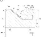
- FIG. 6 is a view illustrating the cover
- FIG. 7 is a plan view of the cover shown in FIG. 6 .
- the cover 300 is disposed above the rotor core 100.
- the cover 300 may include a cover body 310, a stopper 320, and a guide 330.
- the cover body 310, the stopper 320, and the guide 330 may be described while being classified according to shapes and functional properties thereof but are connected to one another as one means.
- the cover body 310 may be embodied as an annular plate shape.
- the cover body 310 may be divided into an inner portion 311 and an outer portion 312.
- the inner portion 311 is an internal part of the cover body 310 which forms an inner circumferential surface 311a.
- the outer portion 312 is an external part of the cover body 310 which forms an outer circumferential surface.
- the stopper 320 may be formed on the inner portion 311.
- a combinational groove portion 313 which induces combination of the protrusion portion 420 may be formed on the outer portion 312.
- a position of the stopper 320 may correspond to a position of the magnet 200.
- the stopper 320 may be located in a central part of an area shown as M of FIG. 7 .
- the stopper 320 is provided such that a reference line CL passes a center of M of FIG. 7 and the center C on the basis of the circumferential direction. Since a combinational force between the magnet 200 and the can member 400 may be weak near the center of the magnet 200 on the basis of the circumferential direction, the stopper 320 is disposed around the center of the magnet 200 so as to increase the combinational force of the can member 400.
- the number of the stoppers 320 may be equal to the number of the magnets 200.
- FIG. 8 is a view illustrating the protrusion portion and the stopper
- FIG. 9 is a cross-sectional view illustrating the stopper.
- the outer portion 312 may be formed to be higher than the inner portion 311. That is, when an axial direction of the rotor core 100 is a height direction, a top surface of the outer portion 312 may be formed to be higher than a top surface of the inner portion 311.
- a height HI of the inner portion 311 of the cover body 310 may be formed to be lower than a height H2 of the outer portion 312.
- the top surface of the inner portion 311 may be formed to be a flat plane shape.
- the top surface of the outer portion 312 may include an inclined surface 321.
- the inclined surface 321 of the outer portion 312 may be formed to be inclined toward a center of the rotor core 100.
- An outside of the outer portion 312 forms a step portion on which the protrusion portion 420 moves, and an inside of the outer portion 312 is configured to be connected to the inner portion 311 through the inclined surface 321.
- the protrusion portion 420 of the can member 400 may be formed to be bent along the outer portion 312 and be combined with the cover 300.
- the stopper 320 physically restricts the protrusion portion 420 combined with the cover 300 from being separated therefrom.
- the stopper 320 may include a column portion 331 and a fixing portion 332.
- the column portion 331 protrudes from a top surface of the inner portion 311 of the cover 300.
- the column portion 331 may be formed to be vertical to the top surface of the inner portion 311.
- the fixing portion 332 may be formed to extend horizontally from a fore end of the column portion 331.
- the fixing portion 332 is disposed while being spaced apart from a top surface of the cover 300.
- a length L2 of a bottom surface 332c of the fixing portion 332 may be formed to be longer than a length L1 of a top surface 332b of the fixing portion 332.
- a direction indicated by an arrow O of FIG. 9 is an outward direction
- a position PI of a fore end of the fixing portion 332 is located farther out than a position P2 of a fore end of the protrusion portion 420 on the basis of a radial direction of the cover 300. This is to restrict the protrusion portion 420 from being completely separated from the rotor core 100 when the protrusion portion 420 is spaced apart from the cover 300.
- the fore end of the fixing portion 332 may be formed to tilt. This is to induce an end of the protrusion portion 420 to slide on the fore end of the fixing portion 332 and be located below the fixing portion 332.
- the fore end of the fixing portion 332 includes a curved surface so as to induce the protrusion portion 420 to more easily slide and move on the fore end of the fixing portion 332.
- the protrusion portion 420 of the can member 400 is directly physically combined with the cover 300 so as to exclude use of an additional adhesive for combining the can member 400.
- FIG. 10 is a view illustrating a size of the cover and a size of the stopper.
- the cover 300 may be formed such that an inner radius R does not cover a hole 110 of the rotor core 100. Also, a width W1 of the stopper 320 may be formed to be greater than a width W2 of the protrusion portion 420. To stably prevent the protrusion portion 420 from being separated, it is necessary that the width W1 of the stopper 320 is greater than the width W2 of the protrusion portion 420.
- FIG. 11 is a view illustrating a state of the rotor assembled with the cover
- FIG. 12 is a view illustrating the can member installed above the magnet.
- the guide 330 of the cover 300 may be inserted between the magnets 200 which are adjacent to each other. Afterwards, as shown in FIG. 12 , the can member 400 is mounted while the cover 300 is inserted. Afterwards, the protrusion portion 420 is bent and fixed to the cover 300.
Landscapes
- Engineering & Computer Science (AREA)
- Power Engineering (AREA)
- Chemical & Material Sciences (AREA)
- Combustion & Propulsion (AREA)
- Transportation (AREA)
- Mechanical Engineering (AREA)
- Permanent Field Magnets Of Synchronous Machinery (AREA)
- Iron Core Of Rotating Electric Machines (AREA)
Abstract
Description
- Embodiments relate to a rotor and a motor including the same.
- An electric power steering (EPS) system is an apparatus capable of allowing a driver to safely drive a vehicle by securing circling stability of the vehicle and providing a quick restoring force. The EPS system controls driving of a steering shaft of the vehicle by driving a motor through an electronic control unit (ECU) according to driving conditions sensed by a vehicle speed sensor, a torque angle sensor, a torque sensor, and the like.
- A rotor of the motor of the EPS system may include a magnet. The magnet may be attached to an outer circumferential surface of a rotor core. In the case of the motor, due to structural properties, a variety of types of protectors (molding, can, tube, and the like) are applied to improve durability of assembled magnets.
- Among them, a can type is the most commonly applied method and protects the rotor and prevents separation of the magnets by combining cup-shaped cans with a top and a bottom of an outer circumferential surface of the rotor.
- However, in order to assemble the rotor inside the can, an adhesive is applied to an inside of the can. However, a process of applying the adhesive has a problem of complicating a process of assembling the rotor. Particularly, there is a problem that uniformly applying a fixed quantity of the adhesive to a bonding part between the can and the rotor is very complicated.
- Also, two cans are used such that the number of components increases and manufacturing costs increase.
- The present invention is directed to providing a rotor capable of excluding use of an adhesive and reducing the number of cans and a motor including the same.
- Aspects of the embodiment are not limited to the above-stated aspect, and unstated other aspects can be clearly understood by those skilled in the art from the following description.
- One aspect of the present invention provides a rotor including a rotor core, a cover disposed above the rotor core, a magnet disposed on an outer circumferential surface of the rotor core, and a can member which accommodates the rotor core and the magnet and is combined with the cover. Here, the can member includes at least one protrusion portion which protrudes from an edge and is combined with the cover.
- The can member may include a cylindrical body which surrounds the magnet, and the protrusion portion may be formed on any one side of the body.
- The rotor may include a flange portion which is formed on the other side of the body and internally faces a center of the can member.
- The protrusion portion may be located in a center of the magnet on the basis of a circumferential direction of the rotor core.
- The number of such protrusion portions may be equal to the number of the magnets.
- The cover may include a cover body including an annular inner portion and an outer portion formed outside the inner portion, and the outer portion may be formed to be higher than the inner portion on the basis of an axial direction of the rotor core.
- The protrusion portion may be combined with the outer portion.
- The outer portion may include an inclined surface formed to be inclined toward a center of the rotor core.
- The outer portion may include an engaging groove portion which is formed to be concave and with which the protrusion portion is combined.
- The cover may include a stopper including a protruding column portion and a fixing portion extending from the column portion, and the fixing portion may be disposed above the protrusion portion combined with the cover in a radial direction from a center of the rotor core.
- The column portion may protrude from a top surface of the inner portion, and a fore end of the fixing portion may be located farther out than a fore end of the protrusion portion combined with the cover in the radial direction from the center of the rotor core.
- A bottom surface of the fixing portion may be formed to be longer than a top surface of the fixing portion in the radial direction on the basis of the center of the rotor core, and the fore end of the fixing portion may be formed to tilt.
- The fore end of the fixing portion may include a curved surface.
- The number of such stoppers may be equal to the number of the protrusion portions.
- The number of such stoppers may be equal to the number of the magnets.
- The cover may include a plurality of guides which extend downward from the cover body.
- The guide may be located between the adjacent magnets.
- Another aspect of the present invention provides a rotor including a rotor core, a cover disposed above the rotor core, a magnet disposed on an outer circumferential surface of the rotor core, and a can member which accommodates the rotor core and the magnet and is combined with the cover. Here, the cover includes a plurality of guides extending downward, and the guides are arranged on the outer circumferential surface of the rotor core and arranged inside the can member.
- At least one protrusion portion protruding from an edge of the can member and combined with the cover may be included.
- The cover may include a cover body and a stopper, and the stopper may include a fixing portion disposed above the protrusion portion combined with the cover in a radial direction from a center of the rotor core.
- A fore end of the fixing portion may be located farther out than a fore end of the protrusion portion combined with the cover in the radial direction from the center of the rotor core.
- Another aspect of the present invention provides a motor including a rotor including a rotor core, a cover disposed above the rotor core, a magnet disposed on an outer circumferential surface of the rotor core, and a can member which accommodates the rotor core and the magnet and is combined with the cover, wherein the cover includes a plurality of guides extending downward, and the guides are arranged on the outer circumferential surface of the rotor core and arranged inside the can member, a stator disposed outside the rotor, and a rotating shaft combined with the rotor core.
- Another aspect of the present invention provides a motor including a rotor including a rotor core, a cover disposed above the rotor core, a magnet disposed on an outer circumferential surface of the rotor core, and a can member which accommodates the rotor core and the magnet and is combined with the cover, wherein the can member includes at least one protrusion portion which protrudes from an edge and is combined with the cover, a stator disposed outside the rotor, and a rotating shaft combined with the rotor core.
- According to an embodiment, a protrusion portion formed on an edge of a can is configured to be combined with a cover such that an advantageous effect of excluding use of an adhesive is provided when the can is combined with a rotor core.
- According to an embodiment, a stopper is formed on a cover and restricts a protrusion portion of a can such that an advantageous effect of increasing a combinational force between the can and a rotor core is provided.
-
-
FIG. 1 is a view of a motor according to an embodiment, -
FIG. 2 is a view illustrating a rotor, -
FIG. 3 is an exploded view of the rotor shown inFIG. 2 , -
FIG. 4 is a perspective view illustrating a can member, -
FIG. 5 is a bottom view of the can member shown inFIG. 4 , -
FIG. 6 is a view illustrating a cover, -
FIG. 7 is a plan view of the cover shown inFIG. 6 , -
FIG. 8 is a view illustrating a protrusion portion and a stopper, -
FIG. 9 is a cross-sectional view illustrating the stopper, -
FIG. 10 is a view illustrating a size of the cover and a size of the stopper, -
FIG. 11 is a view illustrating a state of the rotor assembled with the cover, and -
FIG. 12 is a view illustrating the can member installed above a magnet. - Hereinafter, exemplary embodiments of the present invention will be described in detail with reference to the attached drawings. The purpose, particular advantages, and novel features of the present invention will be more clearly understood from the following detailed description and exemplary embodiments related to the attached drawings. Also, the terms used in the specification and the claims should not be limited to general or lexical meanings and should be interpreted as meanings and concepts coinciding with the technical concept of the present invention on the basis of a principle in which the inventor can appropriately define the concept of the terms to describe the invention in the best manner. Also, a detailed description on well-known related art that may unnecessarily obscure the essential of the present invention will be omitted.
-
FIG. 1 is a view of a motor according to an embodiment. - Referring to
FIG. 1 , the motor according to the embodiment may include arotor 10, astator 20, a rotatingshaft 30, and asensing magnet 40. - The
rotor 10 rotates due to an electrical interaction with thestator 20. - A coil is wound on the
stator 20 to cause the electrical interaction with therotor 10. A detailed configuration of thestator 20 with the coil wound thereon is as follows. Thestator 20 may include a stator core including a plurality of teeth. The stator core may include an annular yoke portion and the teeth on which the coil is wound from the yoke toward a center. The teeth may be provided at certain intervals along an outer circumferential surface of the yoke portion. Meanwhile, the stator core may be formed by stacking a plurality of plates having a thin steel plate shape. Also, the stator core may be formed by combining and connecting a plurality of divided cores to one another. - An insulator is combined with the teeth of the stator so as to insulate the coil from the stator core to not mutually apply a current.
- The rotating
shaft 30 may be combined with therotor 10. When an electromagnetic interaction occurs between therotor 10 and thestator 20 through supplying a current, therotor 10 rotates, and therotating shaft 30 rotates in connection therewith. The rotatingshaft 30 may be connected to a steering shaft to transfer power to the steering shaft. The rotatingshaft 30 may be supported by a bearing. - The
sensing magnet 40 is an apparatus which is combined with the rotatingshaft 30 to interwork with therotor 10 so as to detect a position of therotor 10. The sensing magnet may include a magnet and a sensing plate. The magnet and the sensing plate may be combined with each other to be coaxial. - A sensor which senses a magnetic force of the sensing magnet may be disposed on a printed circuit board (PCB) 50. Here, the sensor may be a hall integrated chip (IC). The sensor senses changes in N pole and S pole of a main magnet or a sub magnet and generates a sensing signal. The
PCB 50 may be combined with a bottom surface of a cover of a housing and may be installed above the sensing magnet such that the sensor faces the sensing magnet. - Meanwhile, the
rotor 10 may include a rotor core and a magnet combined with the rotor core. Therotor 10 may have a variety of shapes according to a method of combining the rotor core with the magnet. Among rotors having a variety of shapes, a motor may include a rotor in which a magnet is combined with an outer circumferential surface of a rotor core. Therotor 10 having this configuration may include an additional can member combined with the rotor core to prevent the magnet from being separated and to increase a combinational force. -
FIG. 2 is a view illustrating the rotor, andFIG. 3 is an exploded view of the rotor shown inFIG. 2 . - Referring to
FIGS. 2 and3 , therotor 10 may include arotor core 100, amagnet 200, acover 300, and acan member 400. In describing the embodiment, it should be noted that a center C of therotor core 100 is equal to a center C of thecan member 400. - The
rotor core 100 may be embodied as a shape in which a plurality of plates having a circular thin steel plate shape are stacked or embodied as one cylindrical shape. A hole with which therotating shaft 30 is combined may be formed in the center of therotor core 100. A protrusion which guides themagnet 200 may protrude from an outer circumferential surface of therotor core 100. - The
magnet 200 may be attached to the outer circumferential surface of therotor core 100. A plurality ofsuch magnets 200 may be arranged at certain intervals along a perimeter of therotor core 100. - The
cover 300 may be combined with a top surface or a bottom surface of therotor core 100. Thecover 300 is combined with thecan member 400 and fixes thecan member 400. - The
can member 400 surrounds themagnet 200 so as to fix themagnet 200 not to be separated from therotor core 100. Also, thecan member 400 prevents themagnet 200 from being exposed. -
FIG. 4 is a perspective view illustrating the can member, andFIG. 5 is a bottom view of the can member shown inFIG. 4 . - Referring to
FIGS. 3 and5 , thecan member 400 may include abody 410, aprotrusion portion 420, and aflange portion 430. It should be noted in advance that thebody 410, theprotrusion portion 420, and theflange portion 430 may be described while being classified according to shapes and functional properties thereof but are connected to one another as one means. Thecan member 400 may be formed of an aluminum material. - The
body 410 may have a cylindrical shape. A top and a bottom of thebody 410 may be formed in an open state. Therotor core 100 is located in thebody 410. Also, thebody 410 surrounds themagnet 200. - The
protrusion portion 420 is combined with thecover 300 and fixes thecan member 400 to therotor core 100. Theprotrusion portion 420 may be formed on an edge of a top end of thebody 410. Theprotrusion portion 420 may be embodied as a sectioned shape formed by extending thebody 410. A plurality ofsuch protrusion portions 420 may be provided at certain intervals along the edge of the top end of thebody 410. Here, the number of theprotrusion portions 420 may be equal to the number of themagnets 200. Also, theprotrusion portion 420 may be embodied as a quadrangular section shape. Theprotrusion portion 420 in a quadrangular shape has high processability and is easily bendable for being combined with thecover 300 so as to be easily assembled. - The
flange portion 430 may be formed on an edge of a bottom end of thebody 410. In detail, theflange portion 430 may be formed by extending from the edge of the bottom end of thebody 410 and being bent toward the center C of thecan member 400. Theflange portion 430 comes into contact with the bottom surface of therotor core 100. -
FIG. 6 is a view illustrating the cover, andFIG. 7 is a plan view of the cover shown inFIG. 6 . - Referring to
FIGS. 6 and7 , thecover 300 is disposed above therotor core 100. Thecover 300 may include acover body 310, astopper 320, and aguide 330. Thecover body 310, thestopper 320, and theguide 330 may be described while being classified according to shapes and functional properties thereof but are connected to one another as one means. - The
cover body 310 may be embodied as an annular plate shape. Thecover body 310 may be divided into aninner portion 311 and anouter portion 312. Theinner portion 311 is an internal part of thecover body 310 which forms an innercircumferential surface 311a. Theouter portion 312 is an external part of thecover body 310 which forms an outer circumferential surface. Thestopper 320 may be formed on theinner portion 311. Acombinational groove portion 313 which induces combination of theprotrusion portion 420 may be formed on theouter portion 312. - A position of the
stopper 320 may correspond to a position of themagnet 200. When an area such as M ofFIG. 7 is referred to as a position area to which themagnet 200 is attached in a circumferential direction on the basis of the center C, thestopper 320 may be located in a central part of an area shown as M ofFIG. 7 . - In detail, the
stopper 320 is provided such that a reference line CL passes a center of M ofFIG. 7 and the center C on the basis of the circumferential direction. Since a combinational force between themagnet 200 and thecan member 400 may be weak near the center of themagnet 200 on the basis of the circumferential direction, thestopper 320 is disposed around the center of themagnet 200 so as to increase the combinational force of thecan member 400. - Meanwhile, the number of the
stoppers 320 may be equal to the number of themagnets 200. -
FIG. 8 is a view illustrating the protrusion portion and the stopper, andFIG. 9 is a cross-sectional view illustrating the stopper. - Referring to
FIGS. 8 and9 , theouter portion 312 may be formed to be higher than theinner portion 311. That is, when an axial direction of therotor core 100 is a height direction, a top surface of theouter portion 312 may be formed to be higher than a top surface of theinner portion 311. - A height HI of the
inner portion 311 of thecover body 310 may be formed to be lower than a height H2 of theouter portion 312. The top surface of theinner portion 311 may be formed to be a flat plane shape. On the other hand, the top surface of theouter portion 312 may include aninclined surface 321. Theinclined surface 321 of theouter portion 312 may be formed to be inclined toward a center of therotor core 100. An outside of theouter portion 312 forms a step portion on which theprotrusion portion 420 moves, and an inside of theouter portion 312 is configured to be connected to theinner portion 311 through theinclined surface 321. - The
protrusion portion 420 of thecan member 400 may be formed to be bent along theouter portion 312 and be combined with thecover 300. - The
stopper 320 physically restricts theprotrusion portion 420 combined with thecover 300 from being separated therefrom. - The
stopper 320 may include acolumn portion 331 and a fixingportion 332. Thecolumn portion 331 protrudes from a top surface of theinner portion 311 of thecover 300. Thecolumn portion 331 may be formed to be vertical to the top surface of theinner portion 311. The fixingportion 332 may be formed to extend horizontally from a fore end of thecolumn portion 331. The fixingportion 332 is disposed while being spaced apart from a top surface of thecover 300. - A length L2 of a
bottom surface 332c of the fixingportion 332 may be formed to be longer than a length L1 of atop surface 332b of the fixingportion 332. Here, when a direction indicated by an arrow O ofFIG. 9 is an outward direction, a position PI of a fore end of the fixingportion 332 is located farther out than a position P2 of a fore end of theprotrusion portion 420 on the basis of a radial direction of thecover 300. This is to restrict theprotrusion portion 420 from being completely separated from therotor core 100 when theprotrusion portion 420 is spaced apart from thecover 300. - The fore end of the fixing
portion 332 may be formed to tilt. This is to induce an end of theprotrusion portion 420 to slide on the fore end of the fixingportion 332 and be located below the fixingportion 332. Here, the fore end of the fixingportion 332 includes a curved surface so as to induce theprotrusion portion 420 to more easily slide and move on the fore end of the fixingportion 332. - As described above, in the rotor according to the embodiment, the
protrusion portion 420 of thecan member 400 is directly physically combined with thecover 300 so as to exclude use of an additional adhesive for combining thecan member 400. -
FIG. 10 is a view illustrating a size of the cover and a size of the stopper. - Referring to
FIG. 10 , thecover 300 may be formed such that an inner radius R does not cover ahole 110 of therotor core 100. Also, a width W1 of thestopper 320 may be formed to be greater than a width W2 of theprotrusion portion 420. To stably prevent theprotrusion portion 420 from being separated, it is necessary that the width W1 of thestopper 320 is greater than the width W2 of theprotrusion portion 420. -
FIG. 11 is a view illustrating a state of the rotor assembled with the cover, andFIG. 12 is a view illustrating the can member installed above the magnet. - Referring to
FIG. 11 , theguide 330 of thecover 300 may be inserted between themagnets 200 which are adjacent to each other. Afterwards, as shown inFIG. 12 , thecan member 400 is mounted while thecover 300 is inserted. Afterwards, theprotrusion portion 420 is bent and fixed to thecover 300. - As described above, the rotor and the motor including the same according to one exemplary embodiment of the present invention have been described in detail with reference to the attached drawings.
- The above description is merely for exemplarily describing the technical concept of the present invention, and a variety of modifications, changes, and replacements thereof may be made by one of ordinary skill in the art without departing from the essential features of the present invention. Accordingly, the embodiments disclosed herein and the attached drawings are not intended to limit and merely explain the technical concept of the present invention, and the scope of the present invention should not be limited by the above embodiment and the attached drawings. The scope of the present invention should be interpreted by the following claims and all technical concepts within the equivalent scope thereof should be interpreted as being included in the scope of the present invention.
Claims (20)
- A rotor comprising:a rotor core;a cover disposed above the rotor core;a magnet disposed on an outer circumferential surface of the rotor core; anda can member which accommodates the rotor core and the magnet and is combined with the cover,wherein the cover comprises a plurality of guides extending downward,wherein the guides are arranged on the outer circumferential surface of the rotor core and arranged inside the can member, andwherein the can member comprises at least one protrusion portion which protrudes from an edge and is combined with the cover.
- The rotor of claim 1, wherein the can member comprises a cylindrical body which surrounds the magnet, and the protrusion portion is formed on any one side of the body.
- The rotor of claim 2, comprising a flange portion which is formed on the other side of the body and internally faces a center of the can member.
- The rotor of claim 1, wherein the protrusion portion is located in a center of the magnet on the basis of a circumferential direction of the rotor core.
- The rotor of claim 1, wherein the number of such protrusion portions is equal to the number of the magnets.
- The rotor of claim 1, wherein the cover comprises a cover body including an annular inner portion and an outer portion formed outside the inner portion, and
wherein the outer portion is formed to be higher than the inner portion on the basis of an axial direction of the rotor core. - The rotor of claim 6, wherein the protrusion portion is combined with the outer portion.
- The rotor of claim 7, wherein the outer portion comprises an inclined surface formed to be gradually inclined toward a center of the rotor core.
- The rotor of claim 8, wherein the outer portion comprises a combinational groove portion which is formed to be concave and with which the protrusion portion is combined.
- The rotor of claim 6, wherein the cover comprises a stopper including a protruding column portion and a fixing portion extending from the column portion, and
wherein the fixing portion is disposed above the protrusion portion combined with the cover in a radial direction from a center of the rotor core. - The rotor of claim 10, wherein the column portion protrudes from a top surface of the inner portion, and a fore end of the fixing portion is located farther out than a fore end of the protrusion portion combined with the cover in the radial direction from the center of the rotor core.
- The rotor of claim 11, wherein a bottom surface of the fixing portion is formed to be longer than a top surface of the fixing portion in the radial direction on the basis of the center of the rotor core, and
wherein the fore end of the fixing portion is formed to tilt. - The rotor of claim 12, wherein the fore end of the fixing portion comprises a curved surface.
- The rotor of claim 10, wherein the number of such stoppers is equal to the number of the protrusion portions.
- The rotor of claim 13, wherein the number of such stoppers is equal to the number of the magnets.
- The rotor of claim 6, wherein the cover comprises a plurality of guides which extend downward from the cover body.
- The rotor of claim 15, wherein the guide is located between the adjacent magnets.
- The rotor of claim 1, wherein the cover includes a cover body and a stopper, and
wherein the stopper comprises a fixing portion disposed above the protrusion portion combined with the cover in a radial direction from a center of the rotor core. - The rotor of claim 18, wherein a fore end of the fixing portion is located farther out than a fore end of the protrusion portion combined with the cover in the radial direction from the center of the rotor core.
- A motor comprising:a rotor which comprises a rotor core, a cover disposed above the rotor core, a magnet disposed on an outer circumferential surface of the rotor core, and a can member which accommodates the rotor core and the magnet and is combined with the cover, wherein the can member comprises at least one protrusion portion protruding from an edge and combined with the cover, wherein the cover comprises a plurality of guides extending downward, and wherein the guides are arranged on the outer circumferential surface of the rotor core and arranged inside the can member;a stator disposed outside the rotor; anda rotating shaft combined with the rotor core.
Applications Claiming Priority (2)
| Application Number | Priority Date | Filing Date | Title |
|---|---|---|---|
| KR1020160073391A KR102589672B1 (en) | 2016-06-13 | 2016-06-13 | Rotor and motor having the same |
| PCT/KR2017/006125 WO2017217729A1 (en) | 2016-06-13 | 2017-06-13 | Rotor and motor including same |
Publications (3)
| Publication Number | Publication Date |
|---|---|
| EP3471241A1 true EP3471241A1 (en) | 2019-04-17 |
| EP3471241A4 EP3471241A4 (en) | 2019-05-22 |
| EP3471241B1 EP3471241B1 (en) | 2021-10-13 |
Family
ID=60664104
Family Applications (1)
| Application Number | Title | Priority Date | Filing Date |
|---|---|---|---|
| EP17813553.9A Active EP3471241B1 (en) | 2016-06-13 | 2017-06-13 | Rotor and motor including same |
Country Status (6)
| Country | Link |
|---|---|
| US (1) | US11230317B2 (en) |
| EP (1) | EP3471241B1 (en) |
| JP (1) | JP6935430B2 (en) |
| KR (1) | KR102589672B1 (en) |
| CN (1) | CN109328426B (en) |
| WO (1) | WO2017217729A1 (en) |
Cited By (1)
| Publication number | Priority date | Publication date | Assignee | Title |
|---|---|---|---|---|
| DE102019205993A1 (en) * | 2019-04-26 | 2020-10-29 | Robert Bosch Gmbh | Protective sleeve for a rotor of an electrical machine as well as a rotor arrangement and an electrical machine |
Families Citing this family (7)
| Publication number | Priority date | Publication date | Assignee | Title |
|---|---|---|---|---|
| KR102626461B1 (en) * | 2018-09-18 | 2024-01-18 | 엘지이노텍 주식회사 | Motor |
| JP2020108299A (en) * | 2018-12-28 | 2020-07-09 | 日本電産株式会社 | Rotor and motor |
| KR102170645B1 (en) | 2019-05-03 | 2020-10-27 | (주)현대케피코 | Rotor of motor and motor including the same |
| JP7383560B2 (en) | 2020-05-20 | 2023-11-20 | 株式会社ミツバ | Rotor, motor, and rotor manufacturing method |
| KR102523498B1 (en) * | 2021-02-23 | 2023-04-20 | 주식회사 씨앤엠 | rotor having integral sensing magnet |
| KR102644305B1 (en) * | 2021-11-25 | 2024-03-07 | 지엠비코리아 주식회사 | Rotor |
| WO2023162997A1 (en) * | 2022-02-28 | 2023-08-31 | ニデック株式会社 | Rotor, rotor manufacturing device, and rotor manufacturing method |
Family Cites Families (24)
| Publication number | Priority date | Publication date | Assignee | Title |
|---|---|---|---|---|
| DE403880C (en) * | 1923-02-27 | 1924-10-10 | Robert Bosch Akt Ges | Field magnet for magneto-electric machines and devices |
| JPS61116955A (en) * | 1984-11-08 | 1986-06-04 | Matsushita Electric Ind Co Ltd | Rotor for motor of magnet rotation type |
| JPH02303339A (en) | 1989-05-15 | 1990-12-17 | Mitsubishi Electric Corp | Electric motor |
| JP2001218403A (en) * | 1999-11-26 | 2001-08-10 | Asmo Co Ltd | Rotating magnetic field motor |
| JP2003037954A (en) * | 2001-07-25 | 2003-02-07 | Asmo Co Ltd | Rotor and brushless motor |
| JP3842196B2 (en) * | 2002-10-02 | 2006-11-08 | 三菱電機株式会社 | Rotating electrical machine rotor |
| JP2004153980A (en) | 2002-11-01 | 2004-05-27 | Kokusan Denki Co Ltd | Flywheel magnet rotor |
| KR20040051676A (en) | 2002-12-11 | 2004-06-19 | 삼성광주전자 주식회사 | Rotor for compressor |
| JP2005020887A (en) * | 2003-06-26 | 2005-01-20 | Mitsuba Corp | Magnet fixing structure and magnet fixing method of rotating electric machine |
| JP4516392B2 (en) * | 2004-09-17 | 2010-08-04 | アスモ株式会社 | Brushless motor rotor, brushless motor, and motor for power steering device |
| KR20070023076A (en) * | 2005-08-23 | 2007-02-28 | 엘지이노텍 주식회사 | Motor |
| JP4671997B2 (en) * | 2007-10-23 | 2011-04-20 | 三菱電機株式会社 | Rotor for rotating electrical machine and method for manufacturing the same |
| KR100990557B1 (en) | 2008-10-24 | 2010-10-29 | 삼성전기주식회사 | Rotating shaft for a ultra slim spindle motor |
| JP5310109B2 (en) * | 2009-03-03 | 2013-10-09 | 日本精工株式会社 | Brushless motor rotor, brushless motor, electric power steering apparatus, and method for manufacturing brushless motor rotor |
| US20100231064A1 (en) * | 2009-03-11 | 2010-09-16 | Gm Global Technology Operations, Inc. | Balance ring for a vehicular electric machine |
| DE102012011444B4 (en) | 2011-06-17 | 2020-11-05 | Denso Corporation | Rotor and motor |
| CN202424336U (en) * | 2011-09-23 | 2012-09-05 | 株洲南车时代电气股份有限公司 | Permanent magnetism motor rotor structure |
| JP5964679B2 (en) * | 2011-10-31 | 2016-08-03 | アスモ株式会社 | Rotor and motor |
| CN103178631B (en) * | 2011-12-26 | 2017-08-08 | 德昌电机(深圳)有限公司 | Rotor |
| DE102012214934A1 (en) * | 2012-08-22 | 2014-02-27 | BSH Bosch und Siemens Hausgeräte GmbH | Electrical machine, in particular electric drive motor |
| CN105359383B (en) * | 2013-05-07 | 2017-11-03 | 日立汽车系统株式会社 | The magnet of electric rotating machine, which disperses, prevents and keeps construction |
| CN103475126B (en) * | 2013-09-29 | 2014-12-10 | 江门市力丰电机有限公司 | Rotor structure of motor and brushless DC motor with same |
| DE202013012411U1 (en) * | 2013-12-05 | 2016-10-18 | Baumüller Directmotion Gmbh | Rotor for an electric machine |
| US20160049845A1 (en) * | 2014-08-12 | 2016-02-18 | Zilift Holdings, Limited | Magnetic rotor shaft module and a rotor assembly incorporating the same |
-
2016
- 2016-06-13 KR KR1020160073391A patent/KR102589672B1/en active IP Right Grant
-
2017
- 2017-06-13 EP EP17813553.9A patent/EP3471241B1/en active Active
- 2017-06-13 JP JP2018564947A patent/JP6935430B2/en active Active
- 2017-06-13 WO PCT/KR2017/006125 patent/WO2017217729A1/en unknown
- 2017-06-13 CN CN201780036938.0A patent/CN109328426B/en active Active
- 2017-06-13 US US16/309,387 patent/US11230317B2/en active Active
Cited By (1)
| Publication number | Priority date | Publication date | Assignee | Title |
|---|---|---|---|---|
| DE102019205993A1 (en) * | 2019-04-26 | 2020-10-29 | Robert Bosch Gmbh | Protective sleeve for a rotor of an electrical machine as well as a rotor arrangement and an electrical machine |
Also Published As
| Publication number | Publication date |
|---|---|
| KR102589672B1 (en) | 2023-10-16 |
| EP3471241A4 (en) | 2019-05-22 |
| US11230317B2 (en) | 2022-01-25 |
| US20190315387A1 (en) | 2019-10-17 |
| CN109328426A (en) | 2019-02-12 |
| KR20170140715A (en) | 2017-12-21 |
| JP2019517770A (en) | 2019-06-24 |
| EP3471241B1 (en) | 2021-10-13 |
| WO2017217729A1 (en) | 2017-12-21 |
| CN109328426B (en) | 2021-04-20 |
| JP6935430B2 (en) | 2021-09-15 |
Similar Documents
| Publication | Publication Date | Title |
|---|---|---|
| EP3471241B1 (en) | Rotor and motor including same | |
| CN107492961B (en) | Rotor and motor having the same | |
| EP3098947A1 (en) | Stator and motor using the same | |
| KR102547567B1 (en) | Motor | |
| JP7222999B2 (en) | Rotor and motor equipped with it | |
| US11418085B2 (en) | Motor for electric power steering and sensing device | |
| KR20200030296A (en) | Motor | |
| JP7288445B2 (en) | motor | |
| KR102566888B1 (en) | Sensing stator and motor having the same | |
| KR20190072894A (en) | Rotor and Motor having the same | |
| US20230208248A1 (en) | Motor unit | |
| KR102491351B1 (en) | Motor | |
| KR20200064531A (en) | Motor | |
| JP7336508B2 (en) | Rotor and motor equipped with the same | |
| KR20190077844A (en) | Stator and motor having the same | |
| KR102584905B1 (en) | Motor | |
| US20230094248A1 (en) | Motor | |
| JP7492575B2 (en) | motor | |
| JP7443363B2 (en) | motor | |
| KR102510261B1 (en) | Rotor and motor having the same | |
| KR102449771B1 (en) | Motor | |
| KR102531472B1 (en) | Sensing stator and motor having the same | |
| KR20210081018A (en) | Motor | |
| KR20200021371A (en) | Motor | |
| KR20200026619A (en) | Motor |
Legal Events
| Date | Code | Title | Description |
|---|---|---|---|
| STAA | Information on the status of an ep patent application or granted ep patent |
Free format text: STATUS: THE INTERNATIONAL PUBLICATION HAS BEEN MADE |
|
| PUAI | Public reference made under article 153(3) epc to a published international application that has entered the european phase |
Free format text: ORIGINAL CODE: 0009012 |
|
| STAA | Information on the status of an ep patent application or granted ep patent |
Free format text: STATUS: REQUEST FOR EXAMINATION WAS MADE |
|
| 17P | Request for examination filed |
Effective date: 20181213 |
|
| AK | Designated contracting states |
Kind code of ref document: A1 Designated state(s): AL AT BE BG CH CY CZ DE DK EE ES FI FR GB GR HR HU IE IS IT LI LT LU LV MC MK MT NL NO PL PT RO RS SE SI SK SM TR |
|
| AX | Request for extension of the european patent |
Extension state: BA ME |
|
| REG | Reference to a national code |
Ref country code: DE Ref legal event code: R079 Ref document number: 602017047659 Country of ref document: DE Free format text: PREVIOUS MAIN CLASS: H02K0001280000 Ipc: H02K0001270000 |
|
| A4 | Supplementary search report drawn up and despatched |
Effective date: 20190425 |
|
| RIC1 | Information provided on ipc code assigned before grant |
Ipc: H02K 1/27 20060101AFI20190417BHEP Ipc: B62D 5/04 20060101ALI20190417BHEP |
|
| DAV | Request for validation of the european patent (deleted) | ||
| DAX | Request for extension of the european patent (deleted) | ||
| STAA | Information on the status of an ep patent application or granted ep patent |
Free format text: STATUS: EXAMINATION IS IN PROGRESS |
|
| 17Q | First examination report despatched |
Effective date: 20200917 |
|
| STAA | Information on the status of an ep patent application or granted ep patent |
Free format text: STATUS: EXAMINATION IS IN PROGRESS |
|
| GRAP | Despatch of communication of intention to grant a patent |
Free format text: ORIGINAL CODE: EPIDOSNIGR1 |
|
| STAA | Information on the status of an ep patent application or granted ep patent |
Free format text: STATUS: GRANT OF PATENT IS INTENDED |
|
| INTG | Intention to grant announced |
Effective date: 20210604 |
|
| GRAS | Grant fee paid |
Free format text: ORIGINAL CODE: EPIDOSNIGR3 |
|
| GRAA | (expected) grant |
Free format text: ORIGINAL CODE: 0009210 |
|
| STAA | Information on the status of an ep patent application or granted ep patent |
Free format text: STATUS: THE PATENT HAS BEEN GRANTED |
|
| AK | Designated contracting states |
Kind code of ref document: B1 Designated state(s): AL AT BE BG CH CY CZ DE DK EE ES FI FR GB GR HR HU IE IS IT LI LT LU LV MC MK MT NL NO PL PT RO RS SE SI SK SM TR |
|
| REG | Reference to a national code |
Ref country code: GB Ref legal event code: FG4D |
|
| REG | Reference to a national code |
Ref country code: CH Ref legal event code: EP |
|
| REG | Reference to a national code |
Ref country code: DE Ref legal event code: R096 Ref document number: 602017047659 Country of ref document: DE |
|
| REG | Reference to a national code |
Ref country code: IE Ref legal event code: FG4D |
|
| REG | Reference to a national code |
Ref country code: AT Ref legal event code: REF Ref document number: 1438884 Country of ref document: AT Kind code of ref document: T Effective date: 20211115 |
|
| REG | Reference to a national code |
Ref country code: NL Ref legal event code: FP |
|
| REG | Reference to a national code |
Ref country code: LT Ref legal event code: MG9D |
|
| REG | Reference to a national code |
Ref country code: AT Ref legal event code: MK05 Ref document number: 1438884 Country of ref document: AT Kind code of ref document: T Effective date: 20211013 |
|
| PG25 | Lapsed in a contracting state [announced via postgrant information from national office to epo] |
Ref country code: RS Free format text: LAPSE BECAUSE OF FAILURE TO SUBMIT A TRANSLATION OF THE DESCRIPTION OR TO PAY THE FEE WITHIN THE PRESCRIBED TIME-LIMIT Effective date: 20211013 Ref country code: LT Free format text: LAPSE BECAUSE OF FAILURE TO SUBMIT A TRANSLATION OF THE DESCRIPTION OR TO PAY THE FEE WITHIN THE PRESCRIBED TIME-LIMIT Effective date: 20211013 Ref country code: FI Free format text: LAPSE BECAUSE OF FAILURE TO SUBMIT A TRANSLATION OF THE DESCRIPTION OR TO PAY THE FEE WITHIN THE PRESCRIBED TIME-LIMIT Effective date: 20211013 Ref country code: BG Free format text: LAPSE BECAUSE OF FAILURE TO SUBMIT A TRANSLATION OF THE DESCRIPTION OR TO PAY THE FEE WITHIN THE PRESCRIBED TIME-LIMIT Effective date: 20220113 Ref country code: AT Free format text: LAPSE BECAUSE OF FAILURE TO SUBMIT A TRANSLATION OF THE DESCRIPTION OR TO PAY THE FEE WITHIN THE PRESCRIBED TIME-LIMIT Effective date: 20211013 |
|
| PG25 | Lapsed in a contracting state [announced via postgrant information from national office to epo] |
Ref country code: IS Free format text: LAPSE BECAUSE OF FAILURE TO SUBMIT A TRANSLATION OF THE DESCRIPTION OR TO PAY THE FEE WITHIN THE PRESCRIBED TIME-LIMIT Effective date: 20220213 Ref country code: SE Free format text: LAPSE BECAUSE OF FAILURE TO SUBMIT A TRANSLATION OF THE DESCRIPTION OR TO PAY THE FEE WITHIN THE PRESCRIBED TIME-LIMIT Effective date: 20211013 Ref country code: PT Free format text: LAPSE BECAUSE OF FAILURE TO SUBMIT A TRANSLATION OF THE DESCRIPTION OR TO PAY THE FEE WITHIN THE PRESCRIBED TIME-LIMIT Effective date: 20220214 Ref country code: PL Free format text: LAPSE BECAUSE OF FAILURE TO SUBMIT A TRANSLATION OF THE DESCRIPTION OR TO PAY THE FEE WITHIN THE PRESCRIBED TIME-LIMIT Effective date: 20211013 Ref country code: NO Free format text: LAPSE BECAUSE OF FAILURE TO SUBMIT A TRANSLATION OF THE DESCRIPTION OR TO PAY THE FEE WITHIN THE PRESCRIBED TIME-LIMIT Effective date: 20220113 Ref country code: LV Free format text: LAPSE BECAUSE OF FAILURE TO SUBMIT A TRANSLATION OF THE DESCRIPTION OR TO PAY THE FEE WITHIN THE PRESCRIBED TIME-LIMIT Effective date: 20211013 Ref country code: HR Free format text: LAPSE BECAUSE OF FAILURE TO SUBMIT A TRANSLATION OF THE DESCRIPTION OR TO PAY THE FEE WITHIN THE PRESCRIBED TIME-LIMIT Effective date: 20211013 Ref country code: GR Free format text: LAPSE BECAUSE OF FAILURE TO SUBMIT A TRANSLATION OF THE DESCRIPTION OR TO PAY THE FEE WITHIN THE PRESCRIBED TIME-LIMIT Effective date: 20220114 Ref country code: ES Free format text: LAPSE BECAUSE OF FAILURE TO SUBMIT A TRANSLATION OF THE DESCRIPTION OR TO PAY THE FEE WITHIN THE PRESCRIBED TIME-LIMIT Effective date: 20211013 |
|
| REG | Reference to a national code |
Ref country code: DE Ref legal event code: R097 Ref document number: 602017047659 Country of ref document: DE |
|
| PG25 | Lapsed in a contracting state [announced via postgrant information from national office to epo] |
Ref country code: SM Free format text: LAPSE BECAUSE OF FAILURE TO SUBMIT A TRANSLATION OF THE DESCRIPTION OR TO PAY THE FEE WITHIN THE PRESCRIBED TIME-LIMIT Effective date: 20211013 Ref country code: SK Free format text: LAPSE BECAUSE OF FAILURE TO SUBMIT A TRANSLATION OF THE DESCRIPTION OR TO PAY THE FEE WITHIN THE PRESCRIBED TIME-LIMIT Effective date: 20211013 Ref country code: RO Free format text: LAPSE BECAUSE OF FAILURE TO SUBMIT A TRANSLATION OF THE DESCRIPTION OR TO PAY THE FEE WITHIN THE PRESCRIBED TIME-LIMIT Effective date: 20211013 Ref country code: EE Free format text: LAPSE BECAUSE OF FAILURE TO SUBMIT A TRANSLATION OF THE DESCRIPTION OR TO PAY THE FEE WITHIN THE PRESCRIBED TIME-LIMIT Effective date: 20211013 Ref country code: DK Free format text: LAPSE BECAUSE OF FAILURE TO SUBMIT A TRANSLATION OF THE DESCRIPTION OR TO PAY THE FEE WITHIN THE PRESCRIBED TIME-LIMIT Effective date: 20211013 Ref country code: CZ Free format text: LAPSE BECAUSE OF FAILURE TO SUBMIT A TRANSLATION OF THE DESCRIPTION OR TO PAY THE FEE WITHIN THE PRESCRIBED TIME-LIMIT Effective date: 20211013 |
|
| PLBE | No opposition filed within time limit |
Free format text: ORIGINAL CODE: 0009261 |
|
| STAA | Information on the status of an ep patent application or granted ep patent |
Free format text: STATUS: NO OPPOSITION FILED WITHIN TIME LIMIT |
|
| 26N | No opposition filed |
Effective date: 20220714 |
|
| PG25 | Lapsed in a contracting state [announced via postgrant information from national office to epo] |
Ref country code: AL Free format text: LAPSE BECAUSE OF FAILURE TO SUBMIT A TRANSLATION OF THE DESCRIPTION OR TO PAY THE FEE WITHIN THE PRESCRIBED TIME-LIMIT Effective date: 20211013 |
|
| PG25 | Lapsed in a contracting state [announced via postgrant information from national office to epo] |
Ref country code: SI Free format text: LAPSE BECAUSE OF FAILURE TO SUBMIT A TRANSLATION OF THE DESCRIPTION OR TO PAY THE FEE WITHIN THE PRESCRIBED TIME-LIMIT Effective date: 20211013 |
|
| PG25 | Lapsed in a contracting state [announced via postgrant information from national office to epo] |
Ref country code: MC Free format text: LAPSE BECAUSE OF FAILURE TO SUBMIT A TRANSLATION OF THE DESCRIPTION OR TO PAY THE FEE WITHIN THE PRESCRIBED TIME-LIMIT Effective date: 20211013 |
|
| REG | Reference to a national code |
Ref country code: CH Ref legal event code: PL |
|
| REG | Reference to a national code |
Ref country code: BE Ref legal event code: MM Effective date: 20220630 |
|
| GBPC | Gb: european patent ceased through non-payment of renewal fee |
Effective date: 20220613 |
|
| PG25 | Lapsed in a contracting state [announced via postgrant information from national office to epo] |
Ref country code: LU Free format text: LAPSE BECAUSE OF NON-PAYMENT OF DUE FEES Effective date: 20220613 Ref country code: LI Free format text: LAPSE BECAUSE OF NON-PAYMENT OF DUE FEES Effective date: 20220630 Ref country code: IE Free format text: LAPSE BECAUSE OF NON-PAYMENT OF DUE FEES Effective date: 20220613 Ref country code: CH Free format text: LAPSE BECAUSE OF NON-PAYMENT OF DUE FEES Effective date: 20220630 |
|
| PG25 | Lapsed in a contracting state [announced via postgrant information from national office to epo] |
Ref country code: IT Free format text: LAPSE BECAUSE OF FAILURE TO SUBMIT A TRANSLATION OF THE DESCRIPTION OR TO PAY THE FEE WITHIN THE PRESCRIBED TIME-LIMIT Effective date: 20211013 Ref country code: GB Free format text: LAPSE BECAUSE OF NON-PAYMENT OF DUE FEES Effective date: 20220613 Ref country code: BE Free format text: LAPSE BECAUSE OF NON-PAYMENT OF DUE FEES Effective date: 20220630 |
|
| PGFP | Annual fee paid to national office [announced via postgrant information from national office to epo] |
Ref country code: NL Payment date: 20230523 Year of fee payment: 7 Ref country code: FR Payment date: 20230522 Year of fee payment: 7 Ref country code: DE Payment date: 20230522 Year of fee payment: 7 |
|
| PG25 | Lapsed in a contracting state [announced via postgrant information from national office to epo] |
Ref country code: HU Free format text: LAPSE BECAUSE OF FAILURE TO SUBMIT A TRANSLATION OF THE DESCRIPTION OR TO PAY THE FEE WITHIN THE PRESCRIBED TIME-LIMIT; INVALID AB INITIO Effective date: 20170613 |
|
| PG25 | Lapsed in a contracting state [announced via postgrant information from national office to epo] |
Ref country code: MK Free format text: LAPSE BECAUSE OF FAILURE TO SUBMIT A TRANSLATION OF THE DESCRIPTION OR TO PAY THE FEE WITHIN THE PRESCRIBED TIME-LIMIT Effective date: 20211013 Ref country code: CY Free format text: LAPSE BECAUSE OF FAILURE TO SUBMIT A TRANSLATION OF THE DESCRIPTION OR TO PAY THE FEE WITHIN THE PRESCRIBED TIME-LIMIT Effective date: 20211013 |