EP3471128A1 - Ensemble comportant un appareil electrique modulaire et un auxiliaire modulaire apte a etre associe audit appareil sur un rail de montage - Google Patents
Ensemble comportant un appareil electrique modulaire et un auxiliaire modulaire apte a etre associe audit appareil sur un rail de montage Download PDFInfo
- Publication number
- EP3471128A1 EP3471128A1 EP18193717.8A EP18193717A EP3471128A1 EP 3471128 A1 EP3471128 A1 EP 3471128A1 EP 18193717 A EP18193717 A EP 18193717A EP 3471128 A1 EP3471128 A1 EP 3471128A1
- Authority
- EP
- European Patent Office
- Prior art keywords
- terminals
- electrical
- auxiliary module
- housing
- electrical apparatus
- Prior art date
- Legal status (The legal status is an assumption and is not a legal conclusion. Google has not performed a legal analysis and makes no representation as to the accuracy of the status listed.)
- Granted
Links
Images


Classifications
-
- H—ELECTRICITY
- H01—ELECTRIC ELEMENTS
- H01H—ELECTRIC SWITCHES; RELAYS; SELECTORS; EMERGENCY PROTECTIVE DEVICES
- H01H45/00—Details of relays
- H01H45/14—Terminal arrangements
-
- H—ELECTRICITY
- H01—ELECTRIC ELEMENTS
- H01H—ELECTRIC SWITCHES; RELAYS; SELECTORS; EMERGENCY PROTECTIVE DEVICES
- H01H71/00—Details of the protective switches or relays covered by groups H01H73/00 - H01H83/00
- H01H71/10—Operating or release mechanisms
- H01H71/12—Automatic release mechanisms with or without manual release
- H01H71/46—Automatic release mechanisms with or without manual release having means for operating auxiliary contacts additional to the main contacts
- H01H71/462—Automatic release mechanisms with or without manual release having means for operating auxiliary contacts additional to the main contacts housed in a separate casing, juxtaposed to and having the same general contour as the main casing
-
- H—ELECTRICITY
- H01—ELECTRIC ELEMENTS
- H01H—ELECTRIC SWITCHES; RELAYS; SELECTORS; EMERGENCY PROTECTIVE DEVICES
- H01H45/00—Details of relays
- H01H45/02—Bases; Casings; Covers
- H01H45/04—Mounting complete relay or separate parts of relay on a base or inside a case
-
- H—ELECTRICITY
- H01—ELECTRIC ELEMENTS
- H01H—ELECTRIC SWITCHES; RELAYS; SELECTORS; EMERGENCY PROTECTIVE DEVICES
- H01H45/00—Details of relays
- H01H45/08—Indicators; Distinguishing marks
-
- H—ELECTRICITY
- H01—ELECTRIC ELEMENTS
- H01H—ELECTRIC SWITCHES; RELAYS; SELECTORS; EMERGENCY PROTECTIVE DEVICES
- H01H71/00—Details of the protective switches or relays covered by groups H01H73/00 - H01H83/00
- H01H71/02—Housings; Casings; Bases; Mountings
- H01H71/0207—Mounting or assembling the different parts of the circuit breaker
- H01H71/0214—Housing or casing lateral walls containing guiding grooves or special mounting facilities
-
- H—ELECTRICITY
- H01—ELECTRIC ELEMENTS
- H01H—ELECTRIC SWITCHES; RELAYS; SELECTORS; EMERGENCY PROTECTIVE DEVICES
- H01H71/00—Details of the protective switches or relays covered by groups H01H73/00 - H01H83/00
- H01H71/02—Housings; Casings; Bases; Mountings
- H01H71/0207—Mounting or assembling the different parts of the circuit breaker
- H01H71/0228—Mounting or assembling the different parts of the circuit breaker having provisions for interchangeable or replaceable parts
Definitions
- the present invention relates to an assembly comprising a modular electrical apparatus and a modular auxiliary adapted to be associated with said apparatus on a mounting rail, said electrical apparatus being housed in a substantially parallelepiped shaped casing and having on one of its faces a set of terminals said upstream, and on a face opposite to the previous relative to the rail, a set of terminals said downstream.
- Modular contactors having a width of 54 mm, which can be equipped on their right with an auxiliary module for signaling the open or closed state of the so-called auxiliary device OF, with a width of 9 mm, are known. all with a length of 63mm.
- the starting devices are electrically connectable to the contactor either directly by cables, or by cables connected to a connecting comb, which comb is electrically connected to said starting devices.
- a connecting comb which comb is electrically connected to said starting devices.
- the present invention solves these problems and proposes an assembly comprising a modular electrical apparatus and an auxiliary module for to be associated with said apparatus, this association does not increase the size of the apparatus and allows the connection of the starting apparatus downstream of the electrical apparatus via a standard connecting comb.
- the subject of the present invention is an assembly of the above-mentioned kind, this assembly being characterized in that the aforementioned first housing comprises a recess adapted to receive the aforementioned auxiliary module, and in that one of the sets of terminals, said first, has terminals having a pitch corresponding to that of a standard comb and extends over substantially the entire width of the device, while the other of the two sets of terminals, said second, has terminals having a reduced pitch compared to the preceding and extends over only a portion of the length of the electrical apparatus, so that the association of this auxiliary module to the aforementioned electrical apparatus, does not increase the size of the apparatus with which it is associated, and allows the electrical connection of the terminals of said first set of terminals to a standard comb.
- the aforementioned recess is adapted to receive instead of the aforementioned auxiliary, a piece forming a hubcap having substantially the same size as the aforementioned auxiliary, when the auxiliary is not intended to be used.
- the so-called first housing comprises a connection part housing the set of said first terminals, this connecting portion extending parallel to the rail beyond the lateral face of said first housing, said face being intended for be attached to the auxiliary module.
- this auxiliary module is housed in a so-called second housing of substantially parallelepiped shape intended to be mounted on the aforementioned rail, said second housing having a side face adapted to to be contiguous to the side face of said first said housing, said upper face adapted to be brought against a so-called inner face belonging to the aforementioned connection portion, and a so-called lower face having electrical connection terminals.
- the auxiliary module or the aforementioned hubcap is associated to the right of the aforementioned electrical apparatus.
- this electrical apparatus is an electric contactor.
- the auxiliary module is a signaling auxiliary of the open or closed position of the electrical apparatus.
- this auxiliary module is actuated by means for transmitting the movement of a contact-carrying shaft belonging to the electrical apparatus.
- the electrical apparatus is of the three-pole or tetra-polar type.
- connection terminals of the set said first are the downstream terminals of the device.
- the aforementioned standard comb is of the three-pole or tetra-polar type, with the interposition of a neutral tooth between two successive phase teeth.
- the present invention further relates to an assembly comprising the previously mentioned features taken alone or in combination, the electrical apparatus being a contactor.
- the present invention also relates to an electrical panel comprising at least one assembly comprising the previously mentioned features taken alone or in combination.
- the subject of the present invention is also an auxiliary signaling module in an assembly comprising the aforementioned features taken alone or in combination, this module being characterized in that it is housed in a substantially parallelepiped-shaped casing said second, said housing enclosing two electrical circuits each comprising a switch, each electrical circuit being electrically connected at one of its ends to a power supply terminal, and at its opposite end to a connection terminal to a signaling means, these two means signaling being intended to signal for one, an open state of the apparatus, and for the other, a closed state of the apparatus, the two aforementioned switches being controlled by a means of transmitting the movement of the shaft driving the contacts of the electrical apparatus so that the transmission means is mobile and a first position in which the first electrical switch is closed and the second open, and a second position in which the first switch is open and the second closed.
- the present invention also relates to a modular electrical device housed in a substantially parallelepiped shaped housing and having on one of its faces, a set of so-called upstream terminals, and on a face opposite to the previous one relative to the rail, a set of terminals said downstream, this apparatus being characterized in that the aforementioned housing comprises a recess adapted to receive an auxiliary module or a piece forming a hubcap having substantially the same size as the aforementioned auxiliary module, and in that one sets of terminals, said first, has terminals having a pitch corresponding to that of a standard comb and extends over substantially the entire length of the apparatus, while the other of the two sets of terminals, said second, has terminals having a reduced pitch compared to the preceding and extends over only a portion of the length of the electrical apparatus, so that the auxiliary module, after association with the aforementioned electrical apparatus, does not increase the size of the apparatus with which it is associated, and allows the electrical connection of the terminals of said first set of terminals to a
- this apparatus is a contactor.
- this apparatus has a width of about 63 mm.
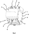
- a contactor 1 of the tetra polar type associated with an auxiliary signaling module 2 the whole being intended to be mounted on a mounting rail.
- This contactor 1 and this auxiliary module 2 are each mounted in a housing 3,4, all of the two housings together in the association having a substantially parallelepiped shape.
- This contactor 1 comprises on one side of the mounting rail, a set 5 of connection terminals said first, intended to allow the electrical connection of the contactor 1 to the starting apparatus D to be mounted to the right of the contactor, and the on the other side of the rail, a set of said second connection terminals intended to be electrically connected to power supply cables, this contactor therefore being of the type fed from the bottom.
- the terminals of the set of terminals 5 said first have a pitch allowing them to be connected to a P-connection comb said standard type tetra polar, while the terminals of the set 6 of connection said second, have a pitch specific to that of the contactors, that is to say, not allowing to be connected to a standard P connection comb.
- this connecting part R comprising the set 5 of connection terminals, said first, comprises a first neutral terminal 7 intended to receive a first neutral tooth of the comb P, then three phase terminals 8, 9, 10 for respectively receive three phase teeth p of the comb P, with between two successive phase terminals, a recess e intended to receive a neutral tooth n of the comb P, said comb comprising in a manner known per se a set of teeth of phase p consecutive with interposition of a neutral tooth n between two successive phase teeth p.
- the so-called first connection portion R comprising the set of said first terminals, has a width greater than the width of the so-called second connection portion S housing the terminals of the set of terminals said second, so that this first connecting portion R extends beyond the connecting face a of the housing 3 of the contactor 1 intended to be contiguous to the auxiliary module 2.
- the housing 3 of the contactor 1 said first, has a recess i of substantially parallelepiped shape for receiving the said second housing 4 of corresponding form belonging to the auxiliary module 2, said housing said second bearing on the housing 3 of the contactor 1 via one side, a side face b adapted to be brought into contact with the side face a located on the same side belonging to the contactor 1, and secondly, a so-called upper face e c able to be brought into contact with an inner face d located opposite the rail U, belonging to the first connection portion R of the contactor.
- the auxiliary module 2 has connection terminals only on one side of the mounting rail U.
- the assembly thus formed has a width of 63 mm, the lower part of this assembly corresponding to that of an assembly according to the prior art, only the upper part of this assembly being different so as to allow the electrical connection of the downstream terminals of the device 1 to a standard comb P.
- the auxiliary module 2 is a signaling module of the open or closed state of the electrical modular apparatus 1 which is an electric switch.
- this assembly E comprises instead of the auxiliary signaling module 2, a piece forming a hubcap 14, intended to replace this auxiliary module 2 when no auxiliary module is intended for to be used.
- This part consists of a housing 15 having substantially the same shape as the aforementioned auxiliary module 2, and is adapted to be placed in the aforementioned recess i so that the size of the contactor 1 is not increased, as this is already the case when an auxiliary module is associated with the contactor.
- an assembly comprising, mounted on a mounting rail U, a contactor 1 to which is associated on the right side, an auxiliary signaling module 2, this assembly being intended to be fed from below by means of cables, and being intended to be electrically connected downstream to a number of starting devices D such as circuit breakers or the like, by means of a standard three-pole and neutral connection comb P.
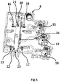
- the auxiliary signaling module 2 is housed in a housing 4 having a face f having a recess g for mounting the housing on the rail U, the auxiliary module 2 being intended to be fixed on the housing 3 of the contactor 1.
- This housing 4 comprises a connection portion T having three terminals 11, 12, 13 located on one side of the aforementioned recess g, these terminals being presented in a stepped manner, so as to facilitate the connection.
- These three terminals respectively first, second and third, are intended to be electrically connected respectively to an open-state signaling means of the electrical modular apparatus, to a power supply means, and to a signaling means of the closed state of the modular apparatus, these various means not being shown in these figures.
- This so-called second housing 4 encloses two electrical circuits 16, 17 each having a switch 18, 19, the first 16 of these circuits being connected at one of its ends to the so-called first terminal 11 and at its other end to the said second terminal 12, while the second circuit 17 is connected at one of its ends to said third terminal 13 and at its other end to said second terminal 12,
- This so-called second housing 4 also encloses a means 20 for transmitting the movement of the contact-carrier shaft of the contactor 1 to the auxiliary module 2, this transmission means comprising a support 21 slidably mounted relative to the so-called second housing 4 and capable of actuating the two switches 18, 19 so that when the contacts of the contactor are closed, the switch 19 of the second circuit 17 is closed while the switch 18 of the first circuit 16 is open, and when the contacts of the contactor are open, the switch 18 of the first circuit 16 is open while that 19 of the second circuit 17 is closed.
- This support 21 is advantageously formed by two flanges 22,23 secured to one another by means of crosspieces 24 distributed over the length of the flanges, said crosspieces 24 being able to cooperate with the switches 18, 19, this support 21 being mechanically connected to the aforementioned shaft.
- an auxiliary module 2 can be associated to the right of a modular contactor 1 so as to signal the open or closed position of the contactor 1.
- This auxiliary module after association does not increase the size of the contactor 1 to which it is associated and allows the connection of the starting apparatus D by a comb P downstream of the contactor 1.
- This signaling auxiliary 2 of the state of the contacts is advantageously associable to the right of the contactors 1, after having removed the trim 14.
- contactors are advantageously of the tripolar or tetra polar type.
- the invention could be envisaged to apply the invention to a contactor having two poles and two terminals, the comb being in this case of the phase and neutral type.
- the invention is advantageously applicable to any equipment, such as an electrical panel, incorporating modular contactors group head.
- This new contactor keeps the possibility to be connected by cables upstream and downstream.
- This device does not modify the operating principle of current contactors. The means of measurement, control, verification and validation will be the same as those of the current contactor.
Landscapes
- Physics & Mathematics (AREA)
- Electromagnetism (AREA)
- Switch Cases, Indication, And Locking (AREA)
- Connections Arranged To Contact A Plurality Of Conductors (AREA)
Abstract
Description
- La présente invention concerne un ensemble comportant un appareil électrique modulaire et un auxiliaire modulaire apte à être associé audit appareil sur un rail de montage, ledit appareil électrique étant logé dans un boîtier de forme sensiblement parallélépipédique et comportant sur l'une de ses faces, un ensemble de bornes dites amont, et sur une face opposée à la précédente par rapport au rail, un ensemble de bornes dites aval.
- On connaît des contacteurs modulaires, présentant une largeur de 54 mm, pouvant être équipés à leur droite d'un module auxiliaire de signalisation de l'état ouvert ou fermé de l'appareil, dit auxiliaire OF, d'une largeur de 9 mm, le tout présentant une longueur de 63mm.
Dans ce type d'ensemble, les appareils de départ sont raccordables électriquement au contacteur soit directement par des câbles, ou bien par des câbles reliés à un peigne de raccordement, lequel peigne est relié électriquement auxdits appareils de départ.
Ainsi, il n'est pas possible de raccorder ces appareils de départ directement au contacteur par l'intermédiaire d'un peigne standard. - La présente invention résout ces problèmes et propose un ensemble comportant un appareil électrique modulaire et un module auxiliaire destiné à être associé audit appareil, cette association n'augmentant pas l'encombrement de l'appareil et permettant le raccordement des appareils de départ à l'aval de l'appareil électrique par l'intermédiaire d'un peigne de raccordement standard.
- A cet effet, la présente invention a pour objet un ensemble du genre précédemment mentionné, cet ensemble étant caractérisé en ce que le boîtier précité dit premier comporte un évidement apte à recevoir le module auxiliaire précité, et en ce que l'un des ensembles de bornes, dit premier, comporte des bornes présentant un pas correspondant à celui d'un peigne standard et s'étend sur sensiblement toute la largeur de l'appareil, tandis que l'autre des deux ensembles de bornes, dit second, comporte des bornes présentant un pas réduit par rapport au précédent et s'étend sur une partie seulement de la longueur de l'appareil électrique, de manière que l'association de ce module auxiliaire à l'appareil électrique précité, n'augmente pas l'encombrement de l'appareil auquel il est associé, et permette le raccordement électrique des bornes dudit premier ensemble de bornes à un peigne standard.
- Selon une caractéristique particulière, l'évidement précité est apte à recevoir à la place de l'auxiliaire précité, une pièce formant un enjoliveur présentant sensiblement le même encombrement que l'auxiliaire précité, lorsque cet auxiliaire n'est pas destiné à être utilisé.
- Selon une caractéristique particulière, le boîtier dit premier comporte une partie de raccordement logeant l'ensemble de bornes dit premier, cette partie de raccordement s'étendant parallèlement au rail au-delà de la face latérale du boîtier dit premier, ladite face étant destinée à être accolée au module auxiliaire.
- Selon une autre caractéristique, ce module auxiliaire est logé dans un boîtier dit second de forme sensiblement parallélépipédique destiné à être monté sur le rail précité, ce boîtier dit second comportant une face latérale apte à être accolée à la face latérale du boîtier dit premier précitée, une face dite supérieure apte à être amenée contre une face dite intérieure appartenant à la partie de raccordement précitée, et une face dite inférieure comportant des bornes de raccordement électriques.
- Selon une autre caractéristique, le module auxiliaire ou l'enjoliveur précité, est associé à droite de l'appareil électrique précité.
- Selon une caractéristique particulière, cet appareil électrique est un contacteur électrique.
- Selon une caractéristique particulière, le module auxiliaire est un auxiliaire de signalisation de la position ouverte ou fermée de l'appareil électrique.
- Selon une autre caractéristique, ce module auxiliaire est actionné par des moyens de transmission du mouvement d'un arbre porte contacts appartenant à l'appareil électrique.
- Selon une autre caractéristique, l'appareil électrique est du type tripolaire ou tétra polaire.
- Selon une autre caractéristique, les bornes de raccordement de l'ensemble dit premier sont les bornes aval de l'appareil.
- Selon une autre caractéristique, le peigne standard précité est du type tripolaire ou tétra polaire, avec interposition d'une dent de neutre entre deux dents de phase successives.
- La présente invention a encore pour objet un ensemble comportant les caractéristiques précédemment mentionnées prises seules ou en combinaison, l'appareil électrique étant un contacteur.
- La présente invention a encore pour objet un tableau électrique comportant au moins un ensemble comportant les caractéristiques précédemment mentionnées prises seules ou en combinaison.
- La présente invention a encore pour objet un module auxiliaire de signalisation dans un ensemble comportant les caractéristiques précédemment mentionnées prises seules ou en combinaison, ce module étant caractérisé en ce qu'il est logé dans un boîtier de forme sensiblement parallélépipédique dit second, ledit boîtier renfermant deux circuits électriques comportant chacun un interrupteur, chaque circuit électrique étant relié électriquement par l'une de ses extrémités, à une borne d'alimentation électrique, et par son extrémité opposée, à une borne de raccordement à un moyen de signalisation, ces deux moyens de signalisation étant destinés à signaler pour l'un, un état ouvert de l'appareil, et pour l'autre, un état fermé de l'appareil, les deux interrupteurs précités étant commandés par un moyen de transmission du mouvement de l'arbre d'entraînement des contacts de l'appareil électrique, de telle manière que ce moyen de transmission soit mobile entre une première position dans laquelle le premier interrupteur électrique est fermé et le second ouvert, et une seconde position dans laquelle le premier interrupteur est ouvert et le second fermé.
- La présente invention a encore pour objet un appareil électrique modulaire logé dans un boîtier de forme sensiblement parallélépipédique et comportant sur l'une de ses faces, un ensemble de bornes dites amont, et sur une face opposée à la précédente par rapport au rail, un ensemble de bornes dites aval, cet appareil étant caractérisé en ce que le boîtier précité comporte un évidement apte à recevoir un module auxiliaire ou bien une pièce formant un enjoliveur présentant sensiblement le même encombrement que le module auxiliaire précité, et en ce que l'un des ensembles de bornes, dit premier, comporte des bornes présentant un pas correspondant à celui d'un peigne standard et s'étend sur sensiblement toute la longueur de l'appareil, tandis que l'autre des deux ensembles de bornes, dit second, comporte des bornes présentant un pas réduit par rapport au précédent et s'étend sur une partie seulement de la longueur de l'appareil électrique, de manière que ce module auxiliaire, après association à l'appareil électrique précité, n'augmente pas l'encombrement de l'appareil auquel il est associé, et permette le raccordement électrique des bornes dudit premier ensemble de bornes à un peigne standard.
- Selon une caractéristique particulière, cet appareil est un contacteur.
- Selon une autre caractéristique particulière, cet appareil présente une largeur d'environ 63 mm.
- Mais d'autres avantages et caractéristiques de l'invention apparaîtront mieux dans la description détaillée qui suit et se réfère aux dessins annexés donnés uniquement à titre d'exemple et dans lesquels :
- La
figure 1 est une vue en perspective illustrant un ensemble selon une réalisation particulière de l'invention comportant un contacteur associé à un module auxiliaire de signalisation de l'état ouvert ou fermé du contacteur, - La
figure 1a est une vue similaire à lafigure 1 , illustrant le contacteur et le module auxiliaire séparément, - La
figure 2 est une vue similaire à la figure précédente, illustrant un ensemble selon une seconde réalisation de l'invention, dans lequel l'auxiliaire de signalisation est remplacé par un élément formant un enjoliveur, - La
figure 3 est une vue en perspective illustrant un ensemble selon la première réalisation de l'invention monté au côté d'un certain nombre d'appareils de départ sur un rail de montage, les appareils étant reliés électriquement au moyen d'un peigne standard, - La
figure 4 est une vue en perspective d'un module auxiliaire seul, - La
figure 5 est une vue en plan, illustrant la partie intérieure d'un tel module auxiliaire. - Sur la
figure 1 , on voit un ensemble E comportant de manière connue en soi, un contacteur 1 du type tétra polaire associé à un module auxiliaire de signalisation 2, le tout étant destiné à être monté sur un rail de montage.
Ce contacteur 1 et ce module auxiliaire 2 sont montés chacun dans un boîtier 3,4, l'ensemble des deux boîtiers réunis lors de l'association présentant une forme sensiblement parallélépipédique.
Ce contacteur 1 comporte d'un côté du rail de montage, un ensemble 5 de bornes de raccordement dit premier, destiné à permettre le raccordement électrique du contacteur 1 à des appareils de départ D destinés à être montés à droite du contacteur, et de l'autre côté du rail, un ensemble 6 de bornes de raccordement dit second, destinées à être reliées électriquement à des câbles d'alimentation électrique, ce contacteur étant donc du type alimenté par le bas.
Conformément à l'invention, les bornes de l'ensemble 5 de bornes dit premier, présentent un pas leur permettant d'être raccordées à un peigne de raccordement P dit standard du type tétra polaire, tandis que les bornes de l'ensemble 6 de raccordement dit second, présentent un pas propre à celui des contacteurs, c'est-à-dire ne permettant pas d'être raccordées à un peigne de raccordement P de type standard.
Ainsi, cette partie de raccordement R comportant l'ensemble 5 de bornes de raccordement dit premier, comporte une première borne de neutre 7 destinée à recevoir une première dent de neutre du peigne P, puis trois bornes de phase 8,9,10 destinées à recevoir respectivement trois dents de phase p du peigne P, avec entre deux bornes de phases successives, un évidement e destiné à recevoir une dent de neutre n du peigne P, ledit peigne comportant de manière connue en soi un ensemble de dents de phase p consécutives avec interposition d'une dent de neutre n entre deux dents de phase p successives.
Afin de permettre ce raccordement à un peigne standard P, la partie de raccordement R dite première, comportant l'ensemble 5 de bornes dit premier, présente une largeur supérieure à la largeur de la partie de raccordement dite seconde S logeant les bornes de l'ensemble 6 de bornes dit second, de telle manière que cette première partie de raccordement R s'étende au-delà de la face de raccordement a du boîtier 3 du contacteur 1 destinée à être accolée au module auxiliaire 2. Ainsi, le boîtier 3 du contacteur 1, dit premier, présente un évidement i de forme sensiblement parallélépipédique destiné à recevoir le boîtier dit second 4 de forme correspondante appartenant au module auxiliaire 2, ce boîtier dit second prenant appui sur le boîtier 3 du contacteur 1 par l'intermédiaire d'une part, d'une face latérale b apte à être amenée en contact avec la face latérale a située du même côté appartenant au contacteur 1, et d'autre part, d'une face dite supérieure c apte à être amenée en contact avec une face interne d située en regard du rail U, appartenant à la première partie de raccordement R du contacteur.
Ainsi, l'on voit que le module auxiliaire 2 ne comporte des bornes de raccordement que d'un côté du rail de montage U.
Avantageusement, l'ensemble ainsi constitué présente une largeur de 63 mm, la partie inférieure de cet ensemble correspondant à celle d'un ensemble selon l'art antérieur, seule la partie supérieure de cet ensemble étant différente de manière à permettre le raccordement électrique des bornes aval de l'appareil 1 à un peigne standard P.
Dans cette réalisation particulière de l'invention, le module auxiliaire 2 est un module de signalisation de l'état ouvert ou fermé de l'appareil modulaire électrique 1 lequel est un contacteur électrique. - Selon une autre réalisation de l'invention illustrée sur la
figure 2 , cet ensemble E selon l'invention comporte en lieu et place du module auxiliaire de signalisation 2, une pièce formant un enjoliveur 14, destinée à remplacer ce modulaire auxiliaire 2 lorsqu'aucun modulaire auxiliaire n'est destiné à être utilisé. Cette pièce est constituée par un boîtier 15 présentant sensiblement la même forme que celle du module auxiliaire précité 2, et est apte à être placé dans l'évidement précité i de telle manière que l'encombrement du contacteur 1 ne soit pas augmenté, comme ceci est déjà le cas lorsqu'un module auxiliaire est associé au contacteur. - Sur la
figure 3 , l'on voit un ensemble comportant, montés sur même un rail de montage U, un contacteur 1 auquel a été associé à droite, un module auxiliaire de signalisation 2, cet ensemble étant destiné à être alimenté par le bas au moyen de câbles, et étant destiné à être relié électriquement en aval à un certain nombre d'appareils de départ D tels des disjoncteurs ou autres, au moyen d'un peigne de raccordement tripolaire et neutre standard P.
Sur lesfigures 4 et5 , l'on voit que le module auxiliaire de signalisation 2 est logé dans un boîtier 4 présentant une face f comportant un évidement g permettant le montage du boîtier sur le rail U, le module auxiliaire 2 étant destiné à être fixé sur le boîtier 3 du contacteur 1. Ce boîtier 4 comporte une partie de raccordement T comportant trois bornes 11,12,13 situées d'un côté de l'évidement précité g, ces bornes étant présentées de manière étagée, de manière à faciliter le raccordement.
Ces trois bornes, respectivement première, seconde et troisième, sont destinées à être reliées électriquement respectivement à un moyen de signalisation de l'état ouvert de l'appareil modulaire électrique, à un moyen d'alimentation électrique, et à un moyen de signalisation de l'état fermé de l'appareil modulaire, ces différents moyens n'étant pas représentés sur ces figures.
Ce boîtier dit second 4 renferme deux circuits électriques 16,17 comportant chacun un interrupteur 18,19, le premier 16 de ces circuits étant relié à l'une de ses extrémités, à la borne dite première 11 et à son autre extrémité, à la borne dite seconde 12, alors que le second circuit 17 est relié par l'une de ses extrémités, à la borne dite troisième 13 et par son autre extrémité à la borne dite seconde 12, - Ce boîtier dit second 4 renferme également un moyen de transmission 20 du mouvement de l'arbre porte-contacts du contacteur 1 au module auxiliaire 2, ce moyen de transmission comportant un support 21 monté coulissant par rapport au boîtier dit second 4 et apte à actionner les deux interrupteurs 18,19 de manière que lorsque les contacts du contacteur sont fermés, l'interrupteur 19 du second circuit 17 soit fermé alors que l'interrupteur 18 du premier circuit 16 est ouvert, et que lorsque les contacts du contacteur sont ouverts, l'interrupteur 18 du premier circuit 16 soit ouvert alors que celui 19 du second circuit 17 soit fermé. Ce support 21 est avantageusement formé par deux flasques 22,23 solidarisés l'un à l'autre par l'intermédiaire de traverses 24 réparties sur la longueur des flasques, lesdites traverses 24 étant aptes à coopérer avec les interrupteurs 18,19, ce support 21 étant relié mécaniquement à l'arbre précité.
Ainsi, grâce à l'invention, un module auxiliaire 2 peut être associé à droite d'un contacteur modulaire 1 de manière à signaler la position ouverte ou fermée du contacteur 1. Ce module auxiliaire après association, n'augmente pas l'encombrement du contacteur 1 auquel il est associé et permet le raccordement des appareils de départ D par un peigne P à l'aval du contacteur 1.
Cet auxiliaire de signalisation 2 de l'état des contacts est associable avantageusement à droite des contacteurs 1, après avoir retiré l'enjoliveur 14. Ces contacteurs sont avantageusement du type tripolaire ou tétra polaire. Cependant, il pourrait être envisagé d'appliquer l'invention à un contacteur comportant deux pôles et deux bornes, le peigne étant dans ce cas du type phase et neutre.
L'invention s'applique avantageusement à tout équipement, tel un tableau électrique, intégrant des contacteurs modulaires tête de groupe.
Ce nouveau contacteur conserve la possibilité d'être raccordé par câbles à l'amont et l'aval.
Ce dispositif ne modifie pas le principe de fonctionnement des contacteurs actuels. Les moyens de mesure, contrôle, vérification et validation seront les mêmes que ceux du contacteur actuel. - Bien entendu, l'invention n'est pas limitée aux modes de réalisation décrits et illustrés qui n'ont été donnés qu'à titre d'exemple.
- Au contraire, l'invention comprend tous les équivalents techniques des moyens décrits ainsi que leurs combinaisons si celles-ci sont réalisées suivant son esprit.
Claims (16)
- Ensemble comportant un appareil électrique modulaire et un module auxiliaire apte à être associé audit appareil sur un rail de montage, ledit appareil électrique étant logé dans un boîtier de forme sensiblement parallélépipédique et comportant sur l'une de ses faces, un ensemble de bornes dites amont, et sur une face opposée à la précédente par rapport au rail, un ensemble de bornes dites aval,
caractérisé en ce que le boîtier précité dit premier (3), comporte un évidement (i) apte à recevoir le module auxiliaire précité (2) et en ce que l'un (5) des ensembles de bornes, dit premier, comporte des bornes présentant un pas correspondant à celui d'un peigne standard P et s'étend sur sensiblement toute la largeur de l'appareil (1), tandis que l'autre (6) des deux ensembles de bornes (5,6), dit second, comporte des bornes présentant un pas réduit par rapport au précédent et s'étend sur une partie seulement de la longueur de l'appareil électrique (1), de manière que l'association de ce module auxiliaire (2) à l'appareil électrique précité (1), n'augmente pas l'encombrement de l'appareil auquel il est associé, et permette le raccordement électrique des bornes dudit premier ensemble (5) de bornes à un peigne standard P. - Ensemble selon la revendication 1, caractérisé en ce que l'évidement précité (i) est apte à recevoir à la place du module auxiliaire précité (2), une pièce formant un enjoliveur (14) présentant sensiblement le même encombrement que le module auxiliaire précité (2), lorsque ce module auxiliaire (2) n'est pas destiné à être utilisé.
- Ensemble selon la revendication 1 ou 2, caractérisé en ce que le boîtier dit premier (3) comporte une partie de raccordement R logeant l'ensemble (5) de bornes dit premier, cette partie de raccordement R s'étendant parallèlement au rail U, au-delà de la face latérale (a) du boîtier dit premier 3, ladite face étant destinée à être accolée au module auxiliaire (2).
- Ensemble selon la revendication 3, caractérisé en ce que ce module auxiliaire (2) est logé dans un boîtier dit second (4) de forme sensiblement parallélépipédique destiné à être monté sur le rail précité U, ce boîtier dit second (4) comportant une face latérale (b) apte à être accolée à la face latérale (a) du boîtier dit premier (3) précitée, une face dite supérieure (c) apte à être amenée contre une face dite intérieure (d) appartenant à la partie de raccordement précitée R, et une face dite inférieure (f) comportant des bornes de raccordement électriques (11,12,13).
- Ensemble selon l'une quelconque des revendications précédentes, caractérisé en ce que le module auxiliaire (2) ou l'enjoliveur précité (14), est associé à droite de l'appareil électrique précité (1).
- Ensemble selon l'une quelconque des revendications précédentes, caractérisé en ce que le module auxiliaire (2) est un auxiliaire de signalisation de la position ouverte ou fermée de l'appareil électrique (1).
- Ensemble selon la revendication 6, caractérisé en ce que ce module auxiliaire (2) est actionné par des moyens de transmission (20) du mouvement d'un arbre porte contacts appartenant à l'appareil électrique (1).
- Ensemble selon l'une quelconque des revendications précédentes, caractérisé en ce que l'appareil électrique (1) est du type tripolaire ou tétra polaire.
- Ensemble selon l'une quelconque des revendications précédentes, caractérisé en ce que les bornes de raccordement de l'ensemble dit premier (5) sont les bornes aval de l'appareil (1).
- Ensemble selon l'une quelconque des revendications 1 à 9, caractérisé en ce que le peigne standard précité P est du type tripolaire ou tétra polaire, avec interposition d'une dent de neutre n entre deux dents de phase p successives.
- Ensemble selon l'une quelconque des revendications précédentes, caractérisé en ce que cet appareil électrique (1) est un contacteur électrique.
- Tableau électrique comportant au moins un ensemble selon la revendication 11.
- Module auxiliaire de signalisation dans un ensemble selon l'une quelconque des revendications 1 à 11, caractérisé en ce qu'il est logé dans un boîtier (4) de forme sensiblement parallélépipédique dit second, ledit boîtier renfermant deux circuits électriques (16,17) comportant chacun un interrupteur (18,19), chaque circuit électrique (16,17) étant relié électriquement par l'une de ses extrémités, à une borne d'alimentation électrique (12), et par son extrémité opposée, à une borne de raccordement (11,13) à un moyen de signalisation, ces deux moyens de signalisation étant destinés à signaler pour l'un, un état ouvert de l'appareil, et pour l'autre, un état fermé de l'appareil, les deux interrupteurs précités (18,19) étant commandés par un moyen de transmission (20) du mouvement de l'arbre d'entraînement des contacts de l'appareil électrique (1), de telle manière que ce moyen de transmission (20) soit mobile entre une première position dans laquelle le premier interrupteur électrique (18) est fermé et le second (19) ouvert, et une seconde position dans laquelle le premier interrupteur (18) est ouvert et le second (19) fermé.
- Appareil électrique modulaire logé dans un boîtier (3) de forme sensiblement parallélépipédique et comportant sur l'une de ses faces, un ensemble (6) de bornes dites amont, et sur une face opposée à la précédente par rapport au rail U, un ensemble de bornes dites aval (5), caractérisé en ce que le boîtier précité (3) comporte un évidement (i) apte à recevoir un module auxiliaire (2) ou bien une pièce formant un enjoliveur (14) présentant sensiblement le même encombrement que le module auxiliaire précité (2), et en ce que l'un (5) des ensembles de bornes, dit premier, comporte des bornes présentant un pas correspondant à celui d'un peigne standard P et s'étend sur sensiblement toute la longueur de l'appareil, tandis que l'autre (6) des deux ensembles de bornes, dit second, comporte des bornes présentant un pas réduit par rapport au précédent et s'étend sur une partie seulement de la largeur de l'appareil électrique (1), de manière que ce module auxiliaire (2), après association à l'appareil électrique précité (1), n'augmente pas l'encombrement de l'appareil auquel il est associé, et permette le raccordement électrique des bornes dudit premier ensemble (5) de bornes à un peigne standard P.
- Appareil électrique selon la revendication 14, caractérisé en ce que c'est un contacteur (1).
- Appareil électrique selon la revendication 15, caractérisé en ce qu'il présente une largeur d'environ 63mm.
Applications Claiming Priority (1)
| Application Number | Priority Date | Filing Date | Title |
|---|---|---|---|
| FR1759545A FR3072510B1 (fr) | 2017-10-12 | 2017-10-12 | Ensemble comportant un appareil electrique modulaire et un auxiliaire modulaire apte a etre associe audit appareil sur un rail de montage |
Publications (2)
| Publication Number | Publication Date |
|---|---|
| EP3471128A1 true EP3471128A1 (fr) | 2019-04-17 |
| EP3471128B1 EP3471128B1 (fr) | 2021-01-06 |
Family
ID=63294245
Family Applications (1)
| Application Number | Title | Priority Date | Filing Date |
|---|---|---|---|
| EP18193717.8A Active EP3471128B1 (fr) | 2017-10-12 | 2018-09-11 | Ensemble comportant un appareil electrique modulaire et un auxiliaire modulaire apte a etre associe audit appareil sur un rail de montage |
Country Status (4)
| Country | Link |
|---|---|
| EP (1) | EP3471128B1 (fr) |
| CN (1) | CN109659193B (fr) |
| ES (1) | ES2855675T3 (fr) |
| FR (1) | FR3072510B1 (fr) |
Citations (3)
| Publication number | Priority date | Publication date | Assignee | Title |
|---|---|---|---|---|
| EP0357472A1 (fr) * | 1988-08-30 | 1990-03-07 | Hager Electro S.A. | Appareils de commande et/ou de protection électrique, éléments constitutifs de ces appareils et ensembles constitués de ces éléments |
| EP0387158A1 (fr) * | 1989-03-10 | 1990-09-12 | Merlin Gerin | Dispositif d'assemblage et de liaison par peigne d'appareils électriques modulaires |
| EP1814133A1 (fr) * | 2006-01-25 | 2007-08-01 | Mitsubishi Electric Corporation | Dispositif de coupe-circuit |
Family Cites Families (8)
| Publication number | Priority date | Publication date | Assignee | Title |
|---|---|---|---|---|
| DE29918974U1 (de) * | 1999-10-29 | 2001-03-08 | Moeller GmbH, 53115 Bonn | Elektrisches Schutzschaltgerät |
| JP4277198B2 (ja) * | 2003-12-26 | 2009-06-10 | 株式会社日立製作所 | 真空スイッチギヤ |
| CN2914314Y (zh) * | 2006-05-18 | 2007-06-20 | 鹤山市山宝开关厂有限公司 | 漏电断路器的脱扣辅助机构 |
| FR2907963B1 (fr) * | 2006-10-27 | 2009-01-09 | Abb Entrelec Soc Par Actions S | Module de raccordement electrique entre un premier et un second contacteurs et montage inverseur correspondant |
| CN201048281Y (zh) * | 2007-03-06 | 2008-04-16 | 瑞安市工泰电器有限公司 | 电动机保护断路器 |
| FR2949017B3 (fr) * | 2009-08-05 | 2011-06-24 | Abb France | Contacteur electromagnetique avec ses modules et accessoires de connexion |
| CN206363964U (zh) * | 2016-11-16 | 2017-07-28 | 浙江正泰电器股份有限公司 | 断路器 |
| CN106409621B (zh) * | 2016-12-02 | 2019-02-05 | 雷顿电气科技有限公司 | 控制与保护开关电器的辅助模块 |
-
2017
- 2017-10-12 FR FR1759545A patent/FR3072510B1/fr active Active
-
2018
- 2018-09-11 ES ES18193717T patent/ES2855675T3/es active Active
- 2018-09-11 EP EP18193717.8A patent/EP3471128B1/fr active Active
- 2018-09-19 CN CN201811092002.2A patent/CN109659193B/zh active Active
Patent Citations (3)
| Publication number | Priority date | Publication date | Assignee | Title |
|---|---|---|---|---|
| EP0357472A1 (fr) * | 1988-08-30 | 1990-03-07 | Hager Electro S.A. | Appareils de commande et/ou de protection électrique, éléments constitutifs de ces appareils et ensembles constitués de ces éléments |
| EP0387158A1 (fr) * | 1989-03-10 | 1990-09-12 | Merlin Gerin | Dispositif d'assemblage et de liaison par peigne d'appareils électriques modulaires |
| EP1814133A1 (fr) * | 2006-01-25 | 2007-08-01 | Mitsubishi Electric Corporation | Dispositif de coupe-circuit |
Also Published As
| Publication number | Publication date |
|---|---|
| ES2855675T3 (es) | 2021-09-24 |
| FR3072510A1 (fr) | 2019-04-19 |
| CN109659193A (zh) | 2019-04-19 |
| CN109659193B (zh) | 2022-10-18 |
| FR3072510B1 (fr) | 2019-09-27 |
| EP3471128B1 (fr) | 2021-01-06 |
Similar Documents
| Publication | Publication Date | Title |
|---|---|---|
| EP0076719B1 (fr) | Disjoncteur multipolaire à bloc déclencheur amovible | |
| EP0320412B1 (fr) | Disjoncteur multipolaire de calibre élevé constitué par deux boîtiers moulés accolés | |
| EP1151499B1 (fr) | Ensemble electrique interrupteur | |
| EP2409553B1 (fr) | Ensemble de commande comportant un variateur de vitesse et un disjoncteur | |
| FR2787238A1 (fr) | Appareil electrique modulaire tel un disjoncteur | |
| FR3072510B1 (fr) | Ensemble comportant un appareil electrique modulaire et un auxiliaire modulaire apte a etre associe audit appareil sur un rail de montage | |
| EP2204886B1 (fr) | Shunt electrique | |
| EP3333871A1 (fr) | Appareil électrique de coupure d'un courant électrique | |
| EP2192605B1 (fr) | Dispositif de sectionnement d'un circuit électrique et coffret de distribution d'énergie électrique comprenant un tel dispositif de sectionnement | |
| FR3073987A1 (fr) | Systeme electrique comprenant un appareil electrique et un module de connexion interchangeable | |
| FR2722332A1 (fr) | Bloc auxiliaire notamment de signalisation de l'etat de disjoncteurs | |
| FR2787917A1 (fr) | Appareil electrique tel un disjoncteur ou un interrupteur modulaire | |
| EP1933425B1 (fr) | Contact électrique sécurisé | |
| EP3709323B1 (fr) | Appareil électrique destiné à établir ou interrompre le courant dans un circuit électrique | |
| EP1126568B1 (fr) | Ensemble de départ-moteur | |
| EP0996959B1 (fr) | Appareil de coupure electrique pour installation electrique a basse tension alternative | |
| EP1278224A1 (fr) | Dispositif de raccordement électrique de deux appareils électriques montés côte à côte sur un mème support de montage | |
| EP0290300B1 (fr) | Dispositif de connexion rapide de circuits imprimés pour boîtiers modulaires | |
| EP3499540B1 (fr) | Appareil électrique destiné à établir ou interrompre le courant dans un circuit électrique | |
| FR2754401A1 (fr) | Dispositif de connexion electrique entre un appareil de protection tel qu'un interrupteur differentiel et des appareils dependants tels que disjoncteurs divisionnaires et/ou fusibles divisionnaires | |
| CH716204A2 (de) | Interrupteur sectionneur et combiné disjoncteur et interrupteur sectionneur. | |
| FR2900508A1 (fr) | Barre omnibus pour repartition electrique | |
| EP3340269A1 (fr) | Appareil électrique multipolaire à borne de connexion par enfichage direct orientée verticalement et système électrique interrupteur | |
| EP3349306B1 (fr) | Appareil électrique modulaire | |
| FR3088493A1 (fr) | Dispositif de raccordement electrique des bornes aval d'un appareil de protection electrique |
Legal Events
| Date | Code | Title | Description |
|---|---|---|---|
| PUAI | Public reference made under article 153(3) epc to a published international application that has entered the european phase |
Free format text: ORIGINAL CODE: 0009012 |
|
| STAA | Information on the status of an ep patent application or granted ep patent |
Free format text: STATUS: THE APPLICATION HAS BEEN PUBLISHED |
|
| AK | Designated contracting states |
Kind code of ref document: A1 Designated state(s): AL AT BE BG CH CY CZ DE DK EE ES FI FR GB GR HR HU IE IS IT LI LT LU LV MC MK MT NL NO PL PT RO RS SE SI SK SM TR |
|
| AX | Request for extension of the european patent |
Extension state: BA ME |
|
| STAA | Information on the status of an ep patent application or granted ep patent |
Free format text: STATUS: REQUEST FOR EXAMINATION WAS MADE |
|
| 17P | Request for examination filed |
Effective date: 20190429 |
|
| RBV | Designated contracting states (corrected) |
Designated state(s): AL AT BE BG CH CY CZ DE DK EE ES FI FR GB GR HR HU IE IS IT LI LT LU LV MC MK MT NL NO PL PT RO RS SE SI SK SM TR |
|
| GRAP | Despatch of communication of intention to grant a patent |
Free format text: ORIGINAL CODE: EPIDOSNIGR1 |
|
| STAA | Information on the status of an ep patent application or granted ep patent |
Free format text: STATUS: GRANT OF PATENT IS INTENDED |
|
| RIC1 | Information provided on ipc code assigned before grant |
Ipc: H01H 71/46 20060101AFI20200923BHEP Ipc: H01H 71/02 20060101ALI20200923BHEP |
|
| INTG | Intention to grant announced |
Effective date: 20201006 |
|
| GRAS | Grant fee paid |
Free format text: ORIGINAL CODE: EPIDOSNIGR3 |
|
| GRAA | (expected) grant |
Free format text: ORIGINAL CODE: 0009210 |
|
| STAA | Information on the status of an ep patent application or granted ep patent |
Free format text: STATUS: THE PATENT HAS BEEN GRANTED |
|
| AK | Designated contracting states |
Kind code of ref document: B1 Designated state(s): AL AT BE BG CH CY CZ DE DK EE ES FI FR GB GR HR HU IE IS IT LI LT LU LV MC MK MT NL NO PL PT RO RS SE SI SK SM TR |
|
| REG | Reference to a national code |
Ref country code: GB Ref legal event code: FG4D Free format text: NOT ENGLISH |
|
| REG | Reference to a national code |
Ref country code: AT Ref legal event code: REF Ref document number: 1353266 Country of ref document: AT Kind code of ref document: T Effective date: 20210115 Ref country code: CH Ref legal event code: EP |
|
| REG | Reference to a national code |
Ref country code: DE Ref legal event code: R096 Ref document number: 602018011526 Country of ref document: DE |
|
| REG | Reference to a national code |
Ref country code: IE Ref legal event code: FG4D Free format text: LANGUAGE OF EP DOCUMENT: FRENCH |
|
| REG | Reference to a national code |
Ref country code: NL Ref legal event code: MP Effective date: 20210106 |
|
| REG | Reference to a national code |
Ref country code: AT Ref legal event code: MK05 Ref document number: 1353266 Country of ref document: AT Kind code of ref document: T Effective date: 20210106 |
|
| REG | Reference to a national code |
Ref country code: LT Ref legal event code: MG9D |
|
| PG25 | Lapsed in a contracting state [announced via postgrant information from national office to epo] |
Ref country code: LT Free format text: LAPSE BECAUSE OF FAILURE TO SUBMIT A TRANSLATION OF THE DESCRIPTION OR TO PAY THE FEE WITHIN THE PRESCRIBED TIME-LIMIT Effective date: 20210106 Ref country code: PT Free format text: LAPSE BECAUSE OF FAILURE TO SUBMIT A TRANSLATION OF THE DESCRIPTION OR TO PAY THE FEE WITHIN THE PRESCRIBED TIME-LIMIT Effective date: 20210506 Ref country code: NO Free format text: LAPSE BECAUSE OF FAILURE TO SUBMIT A TRANSLATION OF THE DESCRIPTION OR TO PAY THE FEE WITHIN THE PRESCRIBED TIME-LIMIT Effective date: 20210406 Ref country code: HR Free format text: LAPSE BECAUSE OF FAILURE TO SUBMIT A TRANSLATION OF THE DESCRIPTION OR TO PAY THE FEE WITHIN THE PRESCRIBED TIME-LIMIT Effective date: 20210106 Ref country code: GR Free format text: LAPSE BECAUSE OF FAILURE TO SUBMIT A TRANSLATION OF THE DESCRIPTION OR TO PAY THE FEE WITHIN THE PRESCRIBED TIME-LIMIT Effective date: 20210407 Ref country code: FI Free format text: LAPSE BECAUSE OF FAILURE TO SUBMIT A TRANSLATION OF THE DESCRIPTION OR TO PAY THE FEE WITHIN THE PRESCRIBED TIME-LIMIT Effective date: 20210106 Ref country code: BG Free format text: LAPSE BECAUSE OF FAILURE TO SUBMIT A TRANSLATION OF THE DESCRIPTION OR TO PAY THE FEE WITHIN THE PRESCRIBED TIME-LIMIT Effective date: 20210406 |
|
| PG25 | Lapsed in a contracting state [announced via postgrant information from national office to epo] |
Ref country code: LV Free format text: LAPSE BECAUSE OF FAILURE TO SUBMIT A TRANSLATION OF THE DESCRIPTION OR TO PAY THE FEE WITHIN THE PRESCRIBED TIME-LIMIT Effective date: 20210106 Ref country code: PL Free format text: LAPSE BECAUSE OF FAILURE TO SUBMIT A TRANSLATION OF THE DESCRIPTION OR TO PAY THE FEE WITHIN THE PRESCRIBED TIME-LIMIT Effective date: 20210106 Ref country code: RS Free format text: LAPSE BECAUSE OF FAILURE TO SUBMIT A TRANSLATION OF THE DESCRIPTION OR TO PAY THE FEE WITHIN THE PRESCRIBED TIME-LIMIT Effective date: 20210106 Ref country code: AT Free format text: LAPSE BECAUSE OF FAILURE TO SUBMIT A TRANSLATION OF THE DESCRIPTION OR TO PAY THE FEE WITHIN THE PRESCRIBED TIME-LIMIT Effective date: 20210106 Ref country code: SE Free format text: LAPSE BECAUSE OF FAILURE TO SUBMIT A TRANSLATION OF THE DESCRIPTION OR TO PAY THE FEE WITHIN THE PRESCRIBED TIME-LIMIT Effective date: 20210106 |
|
| PG25 | Lapsed in a contracting state [announced via postgrant information from national office to epo] |
Ref country code: IS Free format text: LAPSE BECAUSE OF FAILURE TO SUBMIT A TRANSLATION OF THE DESCRIPTION OR TO PAY THE FEE WITHIN THE PRESCRIBED TIME-LIMIT Effective date: 20210506 |
|
| REG | Reference to a national code |
Ref country code: DE Ref legal event code: R097 Ref document number: 602018011526 Country of ref document: DE |
|
| PG25 | Lapsed in a contracting state [announced via postgrant information from national office to epo] |
Ref country code: CZ Free format text: LAPSE BECAUSE OF FAILURE TO SUBMIT A TRANSLATION OF THE DESCRIPTION OR TO PAY THE FEE WITHIN THE PRESCRIBED TIME-LIMIT Effective date: 20210106 Ref country code: EE Free format text: LAPSE BECAUSE OF FAILURE TO SUBMIT A TRANSLATION OF THE DESCRIPTION OR TO PAY THE FEE WITHIN THE PRESCRIBED TIME-LIMIT Effective date: 20210106 Ref country code: SM Free format text: LAPSE BECAUSE OF FAILURE TO SUBMIT A TRANSLATION OF THE DESCRIPTION OR TO PAY THE FEE WITHIN THE PRESCRIBED TIME-LIMIT Effective date: 20210106 |
|
| PLBE | No opposition filed within time limit |
Free format text: ORIGINAL CODE: 0009261 |
|
| STAA | Information on the status of an ep patent application or granted ep patent |
Free format text: STATUS: NO OPPOSITION FILED WITHIN TIME LIMIT |
|
| PG25 | Lapsed in a contracting state [announced via postgrant information from national office to epo] |
Ref country code: DK Free format text: LAPSE BECAUSE OF FAILURE TO SUBMIT A TRANSLATION OF THE DESCRIPTION OR TO PAY THE FEE WITHIN THE PRESCRIBED TIME-LIMIT Effective date: 20210106 Ref country code: RO Free format text: LAPSE BECAUSE OF FAILURE TO SUBMIT A TRANSLATION OF THE DESCRIPTION OR TO PAY THE FEE WITHIN THE PRESCRIBED TIME-LIMIT Effective date: 20210106 Ref country code: SK Free format text: LAPSE BECAUSE OF FAILURE TO SUBMIT A TRANSLATION OF THE DESCRIPTION OR TO PAY THE FEE WITHIN THE PRESCRIBED TIME-LIMIT Effective date: 20210106 |
|
| 26N | No opposition filed |
Effective date: 20211007 |
|
| PG25 | Lapsed in a contracting state [announced via postgrant information from national office to epo] |
Ref country code: AL Free format text: LAPSE BECAUSE OF FAILURE TO SUBMIT A TRANSLATION OF THE DESCRIPTION OR TO PAY THE FEE WITHIN THE PRESCRIBED TIME-LIMIT Effective date: 20210106 |
|
| PG25 | Lapsed in a contracting state [announced via postgrant information from national office to epo] |
Ref country code: SI Free format text: LAPSE BECAUSE OF FAILURE TO SUBMIT A TRANSLATION OF THE DESCRIPTION OR TO PAY THE FEE WITHIN THE PRESCRIBED TIME-LIMIT Effective date: 20210106 |
|
| REG | Reference to a national code |
Ref country code: DE Ref legal event code: R119 Ref document number: 602018011526 Country of ref document: DE |
|
| REG | Reference to a national code |
Ref country code: CH Ref legal event code: PL |
|
| PG25 | Lapsed in a contracting state [announced via postgrant information from national office to epo] |
Ref country code: IS Free format text: LAPSE BECAUSE OF FAILURE TO SUBMIT A TRANSLATION OF THE DESCRIPTION OR TO PAY THE FEE WITHIN THE PRESCRIBED TIME-LIMIT Effective date: 20210506 Ref country code: MC Free format text: LAPSE BECAUSE OF FAILURE TO SUBMIT A TRANSLATION OF THE DESCRIPTION OR TO PAY THE FEE WITHIN THE PRESCRIBED TIME-LIMIT Effective date: 20210106 |
|
| PG25 | Lapsed in a contracting state [announced via postgrant information from national office to epo] |
Ref country code: LU Free format text: LAPSE BECAUSE OF NON-PAYMENT OF DUE FEES Effective date: 20210911 Ref country code: IE Free format text: LAPSE BECAUSE OF NON-PAYMENT OF DUE FEES Effective date: 20210911 Ref country code: DE Free format text: LAPSE BECAUSE OF NON-PAYMENT OF DUE FEES Effective date: 20220401 |
|
| PG25 | Lapsed in a contracting state [announced via postgrant information from national office to epo] |
Ref country code: LI Free format text: LAPSE BECAUSE OF NON-PAYMENT OF DUE FEES Effective date: 20210930 Ref country code: CH Free format text: LAPSE BECAUSE OF NON-PAYMENT OF DUE FEES Effective date: 20210930 |
|
| PG25 | Lapsed in a contracting state [announced via postgrant information from national office to epo] |
Ref country code: NL Free format text: LAPSE BECAUSE OF NON-PAYMENT OF DUE FEES Effective date: 20210206 Ref country code: CY Free format text: LAPSE BECAUSE OF FAILURE TO SUBMIT A TRANSLATION OF THE DESCRIPTION OR TO PAY THE FEE WITHIN THE PRESCRIBED TIME-LIMIT Effective date: 20210106 |
|
| PG25 | Lapsed in a contracting state [announced via postgrant information from national office to epo] |
Ref country code: HU Free format text: LAPSE BECAUSE OF FAILURE TO SUBMIT A TRANSLATION OF THE DESCRIPTION OR TO PAY THE FEE WITHIN THE PRESCRIBED TIME-LIMIT; INVALID AB INITIO Effective date: 20180911 |
|
| PG25 | Lapsed in a contracting state [announced via postgrant information from national office to epo] |
Ref country code: MK Free format text: LAPSE BECAUSE OF FAILURE TO SUBMIT A TRANSLATION OF THE DESCRIPTION OR TO PAY THE FEE WITHIN THE PRESCRIBED TIME-LIMIT Effective date: 20210106 |
|
| PG25 | Lapsed in a contracting state [announced via postgrant information from national office to epo] |
Ref country code: MT Free format text: LAPSE BECAUSE OF FAILURE TO SUBMIT A TRANSLATION OF THE DESCRIPTION OR TO PAY THE FEE WITHIN THE PRESCRIBED TIME-LIMIT Effective date: 20210106 |
|
| PGFP | Annual fee paid to national office [announced via postgrant information from national office to epo] |
Ref country code: IT Payment date: 20250922 Year of fee payment: 8 |
|
| PGFP | Annual fee paid to national office [announced via postgrant information from national office to epo] |
Ref country code: GB Payment date: 20250923 Year of fee payment: 8 Ref country code: BE Payment date: 20250925 Year of fee payment: 8 |
|
| PGFP | Annual fee paid to national office [announced via postgrant information from national office to epo] |
Ref country code: FR Payment date: 20250925 Year of fee payment: 8 |
|
| PG25 | Lapsed in a contracting state [announced via postgrant information from national office to epo] |
Ref country code: TR Free format text: LAPSE BECAUSE OF FAILURE TO SUBMIT A TRANSLATION OF THE DESCRIPTION OR TO PAY THE FEE WITHIN THE PRESCRIBED TIME-LIMIT Effective date: 20210106 |
|
| PGFP | Annual fee paid to national office [announced via postgrant information from national office to epo] |
Ref country code: ES Payment date: 20251015 Year of fee payment: 8 |