EP3470709A1 - Gasket manufacturing method - Google Patents
Gasket manufacturing method Download PDFInfo
- Publication number
- EP3470709A1 EP3470709A1 EP17809958.6A EP17809958A EP3470709A1 EP 3470709 A1 EP3470709 A1 EP 3470709A1 EP 17809958 A EP17809958 A EP 17809958A EP 3470709 A1 EP3470709 A1 EP 3470709A1
- Authority
- EP
- European Patent Office
- Prior art keywords
- gasket
- bead portion
- molding material
- bead
- top portion
- Prior art date
- Legal status (The legal status is an assumption and is not a legal conclusion. Google has not performed a legal analysis and makes no representation as to the accuracy of the status listed.)
- Granted
Links
Images


Classifications
-
- H—ELECTRICITY
- H01—ELECTRIC ELEMENTS
- H01M—PROCESSES OR MEANS, e.g. BATTERIES, FOR THE DIRECT CONVERSION OF CHEMICAL ENERGY INTO ELECTRICAL ENERGY
- H01M8/00—Fuel cells; Manufacture thereof
- H01M8/02—Details
- H01M8/0271—Sealing or supporting means around electrodes, matrices or membranes
- H01M8/0276—Sealing means characterised by their form
-
- F—MECHANICAL ENGINEERING; LIGHTING; HEATING; WEAPONS; BLASTING
- F16—ENGINEERING ELEMENTS AND UNITS; GENERAL MEASURES FOR PRODUCING AND MAINTAINING EFFECTIVE FUNCTIONING OF MACHINES OR INSTALLATIONS; THERMAL INSULATION IN GENERAL
- F16J—PISTONS; CYLINDERS; SEALINGS
- F16J15/00—Sealings
- F16J15/02—Sealings between relatively-stationary surfaces
- F16J15/06—Sealings between relatively-stationary surfaces with solid packing compressed between sealing surfaces
-
- F—MECHANICAL ENGINEERING; LIGHTING; HEATING; WEAPONS; BLASTING
- F16—ENGINEERING ELEMENTS AND UNITS; GENERAL MEASURES FOR PRODUCING AND MAINTAINING EFFECTIVE FUNCTIONING OF MACHINES OR INSTALLATIONS; THERMAL INSULATION IN GENERAL
- F16J—PISTONS; CYLINDERS; SEALINGS
- F16J15/00—Sealings
- F16J15/02—Sealings between relatively-stationary surfaces
- F16J15/06—Sealings between relatively-stationary surfaces with solid packing compressed between sealing surfaces
- F16J15/08—Sealings between relatively-stationary surfaces with solid packing compressed between sealing surfaces with exclusively metal packing
-
- F—MECHANICAL ENGINEERING; LIGHTING; HEATING; WEAPONS; BLASTING
- F16—ENGINEERING ELEMENTS AND UNITS; GENERAL MEASURES FOR PRODUCING AND MAINTAINING EFFECTIVE FUNCTIONING OF MACHINES OR INSTALLATIONS; THERMAL INSULATION IN GENERAL
- F16J—PISTONS; CYLINDERS; SEALINGS
- F16J15/00—Sealings
- F16J15/02—Sealings between relatively-stationary surfaces
- F16J15/06—Sealings between relatively-stationary surfaces with solid packing compressed between sealing surfaces
- F16J15/08—Sealings between relatively-stationary surfaces with solid packing compressed between sealing surfaces with exclusively metal packing
- F16J15/0818—Flat gaskets
- F16J15/0825—Flat gaskets laminated
-
- F—MECHANICAL ENGINEERING; LIGHTING; HEATING; WEAPONS; BLASTING
- F16—ENGINEERING ELEMENTS AND UNITS; GENERAL MEASURES FOR PRODUCING AND MAINTAINING EFFECTIVE FUNCTIONING OF MACHINES OR INSTALLATIONS; THERMAL INSULATION IN GENERAL
- F16J—PISTONS; CYLINDERS; SEALINGS
- F16J15/00—Sealings
- F16J15/02—Sealings between relatively-stationary surfaces
- F16J15/06—Sealings between relatively-stationary surfaces with solid packing compressed between sealing surfaces
- F16J15/10—Sealings between relatively-stationary surfaces with solid packing compressed between sealing surfaces with non-metallic packing
- F16J15/12—Sealings between relatively-stationary surfaces with solid packing compressed between sealing surfaces with non-metallic packing with metal reinforcement or covering
- F16J15/121—Sealings between relatively-stationary surfaces with solid packing compressed between sealing surfaces with non-metallic packing with metal reinforcement or covering with metal reinforcement
- F16J15/122—Sealings between relatively-stationary surfaces with solid packing compressed between sealing surfaces with non-metallic packing with metal reinforcement or covering with metal reinforcement generally parallel to the surfaces
-
- H—ELECTRICITY
- H01—ELECTRIC ELEMENTS
- H01M—PROCESSES OR MEANS, e.g. BATTERIES, FOR THE DIRECT CONVERSION OF CHEMICAL ENERGY INTO ELECTRICAL ENERGY
- H01M8/00—Fuel cells; Manufacture thereof
- H01M8/02—Details
- H01M8/0271—Sealing or supporting means around electrodes, matrices or membranes
-
- F—MECHANICAL ENGINEERING; LIGHTING; HEATING; WEAPONS; BLASTING
- F16—ENGINEERING ELEMENTS AND UNITS; GENERAL MEASURES FOR PRODUCING AND MAINTAINING EFFECTIVE FUNCTIONING OF MACHINES OR INSTALLATIONS; THERMAL INSULATION IN GENERAL
- F16J—PISTONS; CYLINDERS; SEALINGS
- F16J15/00—Sealings
- F16J15/02—Sealings between relatively-stationary surfaces
- F16J15/06—Sealings between relatively-stationary surfaces with solid packing compressed between sealing surfaces
- F16J15/061—Sealings between relatively-stationary surfaces with solid packing compressed between sealing surfaces with positioning means
-
- F—MECHANICAL ENGINEERING; LIGHTING; HEATING; WEAPONS; BLASTING
- F16—ENGINEERING ELEMENTS AND UNITS; GENERAL MEASURES FOR PRODUCING AND MAINTAINING EFFECTIVE FUNCTIONING OF MACHINES OR INSTALLATIONS; THERMAL INSULATION IN GENERAL
- F16J—PISTONS; CYLINDERS; SEALINGS
- F16J15/00—Sealings
- F16J15/02—Sealings between relatively-stationary surfaces
- F16J15/06—Sealings between relatively-stationary surfaces with solid packing compressed between sealing surfaces
- F16J15/08—Sealings between relatively-stationary surfaces with solid packing compressed between sealing surfaces with exclusively metal packing
- F16J15/0818—Flat gaskets
- F16J2015/085—Flat gaskets without fold over
-
- F—MECHANICAL ENGINEERING; LIGHTING; HEATING; WEAPONS; BLASTING
- F16—ENGINEERING ELEMENTS AND UNITS; GENERAL MEASURES FOR PRODUCING AND MAINTAINING EFFECTIVE FUNCTIONING OF MACHINES OR INSTALLATIONS; THERMAL INSULATION IN GENERAL
- F16J—PISTONS; CYLINDERS; SEALINGS
- F16J15/00—Sealings
- F16J15/02—Sealings between relatively-stationary surfaces
- F16J15/06—Sealings between relatively-stationary surfaces with solid packing compressed between sealing surfaces
- F16J15/08—Sealings between relatively-stationary surfaces with solid packing compressed between sealing surfaces with exclusively metal packing
- F16J15/0818—Flat gaskets
- F16J2015/0856—Flat gaskets with a non-metallic coating or strip
-
- Y—GENERAL TAGGING OF NEW TECHNOLOGICAL DEVELOPMENTS; GENERAL TAGGING OF CROSS-SECTIONAL TECHNOLOGIES SPANNING OVER SEVERAL SECTIONS OF THE IPC; TECHNICAL SUBJECTS COVERED BY FORMER USPC CROSS-REFERENCE ART COLLECTIONS [XRACs] AND DIGESTS
- Y02—TECHNOLOGIES OR APPLICATIONS FOR MITIGATION OR ADAPTATION AGAINST CLIMATE CHANGE
- Y02E—REDUCTION OF GREENHOUSE GAS [GHG] EMISSIONS, RELATED TO ENERGY GENERATION, TRANSMISSION OR DISTRIBUTION
- Y02E60/00—Enabling technologies; Technologies with a potential or indirect contribution to GHG emissions mitigation
- Y02E60/30—Hydrogen technology
- Y02E60/50—Fuel cells
-
- Y—GENERAL TAGGING OF NEW TECHNOLOGICAL DEVELOPMENTS; GENERAL TAGGING OF CROSS-SECTIONAL TECHNOLOGIES SPANNING OVER SEVERAL SECTIONS OF THE IPC; TECHNICAL SUBJECTS COVERED BY FORMER USPC CROSS-REFERENCE ART COLLECTIONS [XRACs] AND DIGESTS
- Y02—TECHNOLOGIES OR APPLICATIONS FOR MITIGATION OR ADAPTATION AGAINST CLIMATE CHANGE
- Y02P—CLIMATE CHANGE MITIGATION TECHNOLOGIES IN THE PRODUCTION OR PROCESSING OF GOODS
- Y02P70/00—Climate change mitigation technologies in the production process for final industrial or consumer products
- Y02P70/50—Manufacturing or production processes characterised by the final manufactured product
Definitions
- the present invention relates to a gasket manufacturing method relating to a sealing technique.
- the gasket of the present invention is used as a fuel cell gasket, for example.
- a gasket 51 which has a structure in which a base material 52 of a plate shape containing a metal plate or the like is provided, a bead portion 53 of a solid shape is provided on one part of a plane of the base material 52, and a gasket body 54 formed of a rubber-like elastic body is disposed in a top portion 53a of the bead portion 53 and which contains a combination of the base material 52 and the gasket body 54 as illustrated in FIG. 4 .
- the base material 52 is used as a fuel cell separator, for example.
- seal lines S are set so as to surround the periphery of a fuel cell reaction surface 55 and the periphery of each manifold hole 56 as illustrated in FIG. 5 . Accordingly, the bead portion 53 is provided and the gasket body 54 is disposed along the seal lines S.
- Patent Document 1 Japanese Unexamined Patent Application Publication No. 2015-191802 (FIGs. 7 to 8)
- the top portion 53a of the bead portion 53 provided on the one part of the plane of the base material 52 is formed into a flat surface shape over the entire width thereof as illustrated in the figure.
- the coating width of the molding material may not be constant due to surface tension.
- the coating thickness of the molding material is also not constant, and thus the cross-sectional shape of the gasket body 54 is not constant. Therefore, the sealability by the gasket body 54 may be affected (In general, the coating amount of the molding material is a fixed amount, and therefore, when the coating width is wide, the coating thickness is thin and, when the coating width is narrow, the coating thickness is thick. The prior-art technique cannot sufficiently control the width dimension and the thickness dimension, i.e., the coating shape of the molding material.).
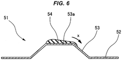
- the molding material of the gasket body 54 in the process of applying the molding material of the gasket body 54 to the top portion 53a of the bead portion 53, the molding material partially bulges out in the width direction from the top portion 53a of the bead portion 53 (flows in a direction indicated by an arrow x) as illustrated in FIG. 6 . In this case, a gasket molding defect occurs.
- a gasket manufacturing method of the present invention is a method for manufacturing a gasket provided with a base material provided with a bead portion on one part of a plane and a gasket body formed of a rubber-like elastic body disposed in a top portion of the bead portion and the method includes sequentially performing a process of forming the bead portion on the one part of the plane of the base material and a process of applying a molding material of the gasket body to the top portion of the bead portion, in which, when forming the bead portion on the one part of the plane of the base material, a protrusion portion is formed in each end portion in the width direction in the top portion of the bead portion and the protrusion portions are utilized as a coating width defining means of the molding material when applying the molding material to the top portion of the bead portion.
- the protrusion portion when forming the bead portion on the one part of the plane of the base material, the protrusion portion is formed in each end portion in the width direction in the top portion of the bead portion and the protrusion portions are utilized as the coating width defining means of the molding material when applying the molding material of the gasket body to the top portion of the bead portion, and therefore the protrusion portions block the flow (spread in the width direction) of the molding material and define the coating width. Therefore, the coating width of the molding material can be made constant or substantially constant and the molding material can be prevented from bulging out.
- the base material is used as a fuel cell separator, for example.
- the gasket is used as a fuel cell gasket.
- the coating width of the gasket body molding material in the top portion of the bead portion can be made constant or substantially constant and the molding material can be prevented from bulging out. Therefore, the cross-sectional shape of the gasket body is constant or substantially constant, so that the sealability by the gasket body can be stabilized, and thus the occurrence of a molding defect due to the bulging-out of the molding material can be prevented.
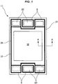
- FIG. 1 illustrates a plane of an entire gasket 11 manufactured by a manufacturing method according to an embodiment of the present invention.
- the gasket 11 is used as a fuel cell gasket.
- the gasket 11 has a fuel cell reaction surface 22 and a plurality of manifold holes 23 on a plane of a fuel cell separator 21 containing a metal plate as a base material, and therefore seal lines S are set on the peripheries thereof.
- a bead portion 24 having a solid shape is integrally provided in the seal line S.
- the bead portion 24 is formed into a full bead shape having a cross section of a substantially trapezoid shape, i.e., a shape in which a top portion 26 is provided between a pair of inclined surface portions 25 in the width direction.
- the bead portion 24 is provided over the entire length of the seal line S.
- the bead portion 24 projects in one direction (upward in the figure) in the thickness direction of the separator 21.
- a protrusion portion 27 is integrally provided in each end portion in the width direction in the top portion 26 of the bead portion 24.
- the protrusion portions 27 are provided over the entire length of the bead portion 24.
- the protrusion portions 27 project in one direction (upward in the figure) in the thickness direction of the separator 21.
- the protrusion portion 27 is provided in each end portion in the width direction of the top portion 26, and therefore a center portion in the width direction of the top portion 26 is relatively formed into a recessed portion 28.
- the recessed portion 28 is also provided over the entire length of the bead portion 24.
- a gasket body 31 containing a rubber-like elastic body is provided in the recessed portion 28, i.e., upper surface of the top portion 26 and between the pair of protrusion portions 27 in the width direction.
- the gasket body 31 is molded by applying a molding material by a means, such as a dispenser method.
- the gasket body 31 is provided over the entire length of the seal lines S.
- the bead portion 24 is formed on the one part of the plane of the separator 21 by press processing or the like, and the protrusion portions 27 are simultaneously formed at this time.
- the molding material (liquid rubber or the like) of the gasket body 31 is applied to the upper surface of the top portion 26 of the bead portion 24 by a means, such as the dispenser method, and a coating process is performed utilizing the protrusion portions 27 as the coating width defining means of the molding material at this time.
- the protrusion portions 27 block the flow (spread in the width direction) of the molding material and define the coating width in the coating process of the molding material described above. Therefore, the coating width is made constant or substantially constant and, when the coating width is made constant or substantially constant, the coating thickness is also made constant or substantially constant because the coating amount is a fixed amount. Accordingly, the cross-sectional shape of the gasket body 31 is made constant or substantially constant, and therefore the sealability by the gasket body 31 can be stabilized and the occurrence of a molding defect by the bulging-out of the molding material can be prevented.
- cross-sectional shape of the protrusion portions 27 is formed into an arc shape and the cross-sectional shape (cross-sectional shape of the bottom surface of the recessed portion 28) of the top portion 26 is also formed into an arc shape
- the cross-sectional shapes thereof may be linear shapes or may contain a combination of a plurality of straight lines.
- the cross-sectional shape of the protrusion portions 27 is formed into a trapezoid shape and the cross-sectional shape (cross-sectional shape of the bottom surface of the recessed portion 28) of the top portion 26 is formed into a flat and linear shape in FIG. 3 .
- the height of the protrusion portion 27 is smaller than the thickness of the gasket body 31, and thus the gasket body 31 can be certainly brought into contact with the mating surface in assembling a fuel cell stack.
Landscapes
- Engineering & Computer Science (AREA)
- General Engineering & Computer Science (AREA)
- Mechanical Engineering (AREA)
- Sustainable Energy (AREA)
- Manufacturing & Machinery (AREA)
- Sustainable Development (AREA)
- Life Sciences & Earth Sciences (AREA)
- Chemical & Material Sciences (AREA)
- Chemical Kinetics & Catalysis (AREA)
- Electrochemistry (AREA)
- General Chemical & Material Sciences (AREA)
- Fuel Cell (AREA)
- Gasket Seals (AREA)
Abstract
Description
- The present invention relates to a gasket manufacturing method relating to a sealing technique. The gasket of the present invention is used as a fuel cell gasket, for example.
- Heretofore, a
gasket 51 is known which has a structure in which abase material 52 of a plate shape containing a metal plate or the like is provided, abead portion 53 of a solid shape is provided on one part of a plane of thebase material 52, and agasket body 54 formed of a rubber-like elastic body is disposed in atop portion 53a of thebead portion 53 and which contains a combination of thebase material 52 and thegasket body 54 as illustrated inFIG. 4 . - The
base material 52 is used as a fuel cell separator, for example. In the fuel cell separator, seal lines S are set so as to surround the periphery of a fuelcell reaction surface 55 and the periphery of eachmanifold hole 56 as illustrated inFIG. 5 . Accordingly, thebead portion 53 is provided and thegasket body 54 is disposed along the seal lines S. - As a procedure of manufacturing the above-described
gasket 51, a process of forming thebead portion 53 on the one part of the plane of thebase material 52 and a process of applying a molding material (liquid rubber or the like) of thegasket body 54 to thetop portion 53a of thebead portion 53, and then molding thegasket body 54 are sequentially performed. - Patent Document 1: Japanese Unexamined Patent Application Publication No.
2015-191802 - However, there is room for further improvement in the above-described prior-art technique in the following respects.
- More specifically, according to the prior-art technique, the
top portion 53a of thebead portion 53 provided on the one part of the plane of thebase material 52 is formed into a flat surface shape over the entire width thereof as illustrated in the figure. - Therefore, in the process of applying the molding material of the
gasket body 54 to thetop portion 53a of thebead portion 53, the coating width of the molding material may not be constant due to surface tension. In this case, the coating thickness of the molding material is also not constant, and thus the cross-sectional shape of thegasket body 54 is not constant. Therefore, the sealability by thegasket body 54 may be affected (In general, the coating amount of the molding material is a fixed amount, and therefore, when the coating width is wide, the coating thickness is thin and, when the coating width is narrow, the coating thickness is thick. The prior-art technique cannot sufficiently control the width dimension and the thickness dimension, i.e., the coating shape of the molding material.). - Moreover, in the process of applying the molding material of the
gasket body 54 to thetop portion 53a of thebead portion 53, the molding material partially bulges out in the width direction from thetop portion 53a of the bead portion 53 (flows in a direction indicated by an arrow x) as illustrated inFIG. 6 . In this case, a gasket molding defect occurs. - In view of the above-described circumstances, it is an object of the present invention to provide a gasket manufacturing method capable of making the coating width of a gasket body molding material in a top portion of a bead portion constant or substantially constant and also capable of preventing the molding material from bulging out.
- In order to achieve the above-described object, a gasket manufacturing method of the present invention is a method for manufacturing a gasket provided with a base material provided with a bead portion on one part of a plane and a gasket body formed of a rubber-like elastic body disposed in a top portion of the bead portion and the method includes sequentially performing a process of forming the bead portion on the one part of the plane of the base material and a process of applying a molding material of the gasket body to the top portion of the bead portion, in which, when forming the bead portion on the one part of the plane of the base material, a protrusion portion is formed in each end portion in the width direction in the top portion of the bead portion and the protrusion portions are utilized as a coating width defining means of the molding material when applying the molding material to the top portion of the bead portion.
- In the present invention having the above-described configuration, when forming the bead portion on the one part of the plane of the base material, the protrusion portion is formed in each end portion in the width direction in the top portion of the bead portion and the protrusion portions are utilized as the coating width defining means of the molding material when applying the molding material of the gasket body to the top portion of the bead portion, and therefore the protrusion portions block the flow (spread in the width direction) of the molding material and define the coating width. Therefore, the coating width of the molding material can be made constant or substantially constant and the molding material can be prevented from bulging out. The base material is used as a fuel cell separator, for example. In this case, the gasket is used as a fuel cell gasket.
- In the present invention, the coating width of the gasket body molding material in the top portion of the bead portion can be made constant or substantially constant and the molding material can be prevented from bulging out. Therefore, the cross-sectional shape of the gasket body is constant or substantially constant, so that the sealability by the gasket body can be stabilized, and thus the occurrence of a molding defect due to the bulging-out of the molding material can be prevented.
-
-
FIG. 1 is a plan view of a gasket according to an embodiment of the present invention. -
FIG. 2 is a cross-sectional view of a principal portion illustrating an example of the cross-sectional shape of the gasket and is an enlarged cross-sectional view along the A-A line ofFIG. 1 . -
FIG. 3 is a cross-sectional view of a principal portion illustrating another example of the cross-sectional shape of the gasket and is an enlarged cross-sectional view along the A-A line ofFIG. 1 . -
FIG. 4 is a cross-sectional view of a principal portion of a gasket according to a prior-art embodiment. -
FIG. 5 is a plan view of the gasket. -
FIG. 6 is an explanatory view illustrating a molding defect in the gasket. -
- (1) The present invention relates to a fuel cell gasket or a metal gasket.
- (2) As the fuel cell gasket, a bead is formed in a separator, and then rubber is applied onto the bead and molded, whereby a cost reduction is expected. In this case, a flat shape is adopted for the bead surface. However, when a gasket is formed using a liquid rubber material by liquid application, such as a screen printing system, the coating cross-sectional shape cannot be controlled due to the surface tension between the rubber material and a base material, and thus the sealability is problematic (Variations in the coating width and height of rubber occur.).
- (3) Then, the present invention stabilizes the coating shape of the liquid rubber material by forming end portions of a bead shape formed in the separator into a protrusion shape. The seal shape can be controlled, and therefore an improvement of the sealability quality can be achieved. A fuel cell gasket has a feature that the separator bead cross-sectional end portions are formed into the protrusion shape. The variation in the rubber height can be prevented without being affected by the surface tension between the base material and the rubber material.
- Hereinafter, an embodiment of the present invention is described according to the drawings.
-
FIG. 1 illustrates a plane of anentire gasket 11 manufactured by a manufacturing method according to an embodiment of the present invention. Thegasket 11 is used as a fuel cell gasket. Thegasket 11 has a fuelcell reaction surface 22 and a plurality ofmanifold holes 23 on a plane of afuel cell separator 21 containing a metal plate as a base material, and therefore seal lines S are set on the peripheries thereof. - As illustrated in the enlarged cross section of
FIG. 2 , abead portion 24 having a solid shape is integrally provided in the seal line S. Thebead portion 24 is formed into a full bead shape having a cross section of a substantially trapezoid shape, i.e., a shape in which atop portion 26 is provided between a pair ofinclined surface portions 25 in the width direction. Thebead portion 24 is provided over the entire length of the seal line S. Thebead portion 24 projects in one direction (upward in the figure) in the thickness direction of theseparator 21. - A
protrusion portion 27 is integrally provided in each end portion in the width direction in thetop portion 26 of thebead portion 24. Theprotrusion portions 27 are provided over the entire length of thebead portion 24. Theprotrusion portions 27 project in one direction (upward in the figure) in the thickness direction of theseparator 21. Theprotrusion portion 27 is provided in each end portion in the width direction of thetop portion 26, and therefore a center portion in the width direction of thetop portion 26 is relatively formed into arecessed portion 28. Therecessed portion 28 is also provided over the entire length of thebead portion 24. - A
gasket body 31 containing a rubber-like elastic body is provided in therecessed portion 28, i.e., upper surface of thetop portion 26 and between the pair ofprotrusion portions 27 in the width direction. Thegasket body 31 is molded by applying a molding material by a means, such as a dispenser method. Thegasket body 31 is provided over the entire length of the seal lines S. - In manufacturing the above-described
gasket 11, thebead portion 24 is formed on the one part of the plane of theseparator 21 by press processing or the like, and theprotrusion portions 27 are simultaneously formed at this time. - Subsequently, the molding material (liquid rubber or the like) of the
gasket body 31 is applied to the upper surface of thetop portion 26 of thebead portion 24 by a means, such as the dispenser method, and a coating process is performed utilizing theprotrusion portions 27 as the coating width defining means of the molding material at this time. - Therefore, according to this method, the
protrusion portions 27 block the flow (spread in the width direction) of the molding material and define the coating width in the coating process of the molding material described above. Therefore, the coating width is made constant or substantially constant and, when the coating width is made constant or substantially constant, the coating thickness is also made constant or substantially constant because the coating amount is a fixed amount. Accordingly, the cross-sectional shape of thegasket body 31 is made constant or substantially constant, and therefore the sealability by thegasket body 31 can be stabilized and the occurrence of a molding defect by the bulging-out of the molding material can be prevented. - In
FIG. 2 , although the cross-sectional shape of theprotrusion portions 27 is formed into an arc shape and the cross-sectional shape (cross-sectional shape of the bottom surface of the recessed portion 28) of thetop portion 26 is also formed into an arc shape, the cross-sectional shapes thereof may be linear shapes or may contain a combination of a plurality of straight lines. - As an example in this case, the cross-sectional shape of the
protrusion portions 27 is formed into a trapezoid shape and the cross-sectional shape (cross-sectional shape of the bottom surface of the recessed portion 28) of thetop portion 26 is formed into a flat and linear shape inFIG. 3 . - As a matter common to the example of
FIG. 2 and the example ofFIG. 3 , it is preferable that the height of theprotrusion portion 27 is smaller than the thickness of thegasket body 31, and thus thegasket body 31 can be certainly brought into contact with the mating surface in assembling a fuel cell stack. -
- 11
- gasket
- 21
- separator (base material)
- 22
- reaction surface
- 23
- manifold hole
- 24
- bead portion
- 25
- inclined surface portion
- 26
- top portion
- 27
- protrusion portion
- 28
- recessed portion
- 31
- gasket body
- S
- seal line
Claims (2)
- A gasket manufacturing method,
the gasket comprising a base material provided with a bead portion on one part of a plane and a gasket body formed of a rubber-like elastic body disposed in a top portion of the bead portion,
the method comprising:sequentially performinga process of forming the bead portion on the one part of the plane of the base material, anda process of applying a molding material of the gasket body to the top portion of the bead portion, whereinwhen forming the bead portion on the one part of the plane of the base material, a protrusion portion is formed in each end portion in a width direction in the top portion of the bead portion, and
the protrusion portions are utilized as a coating width defining means of the molding material when applying the molding material to the top portion of the bead portion. - The gasket manufacturing method according to Claim 1, wherein
the base material is a fuel cell separator.
Applications Claiming Priority (2)
| Application Number | Priority Date | Filing Date | Title |
|---|---|---|---|
| JP2016116062 | 2016-06-10 | ||
| PCT/JP2017/014788 WO2017212775A1 (en) | 2016-06-10 | 2017-04-11 | Gasket manufacturing method |
Publications (4)
| Publication Number | Publication Date |
|---|---|
| EP3470709A1 true EP3470709A1 (en) | 2019-04-17 |
| EP3470709A4 EP3470709A4 (en) | 2019-06-12 |
| EP3470709C0 EP3470709C0 (en) | 2025-06-04 |
| EP3470709B1 EP3470709B1 (en) | 2025-06-04 |
Family
ID=60578491
Family Applications (1)
| Application Number | Title | Priority Date | Filing Date |
|---|---|---|---|
| EP17809958.6A Active EP3470709B1 (en) | 2016-06-10 | 2017-04-11 | Gasket manufacturing method |
Country Status (7)
| Country | Link |
|---|---|
| US (1) | US10950874B2 (en) |
| EP (1) | EP3470709B1 (en) |
| JP (1) | JP6596157B2 (en) |
| KR (1) | KR102354322B1 (en) |
| CN (1) | CN109154387B (en) |
| CA (1) | CA3024080C (en) |
| WO (1) | WO2017212775A1 (en) |
Cited By (1)
| Publication number | Priority date | Publication date | Assignee | Title |
|---|---|---|---|---|
| EP4033574A4 (en) * | 2019-09-18 | 2024-11-06 | NOK Corporation | METHOD FOR PRODUCING A FUEL CELL SEPARATION GASKET |
Families Citing this family (13)
| Publication number | Priority date | Publication date | Assignee | Title |
|---|---|---|---|---|
| JP7261614B2 (en) * | 2019-03-01 | 2023-04-20 | Nok株式会社 | Gasket manufacturing method |
| JP7254003B2 (en) * | 2019-08-27 | 2023-04-07 | Nok株式会社 | Gasket manufacturing method |
| JP7335965B2 (en) * | 2019-09-09 | 2023-08-30 | Nok株式会社 | Seal structure of fuel cell separator |
| JP7038692B2 (en) * | 2019-11-25 | 2022-03-18 | 本田技研工業株式会社 | Separator for fuel cell and power generation cell |
| JP7334128B2 (en) * | 2020-01-31 | 2023-08-28 | Nok株式会社 | Gasket manufacturing method |
| JP7478557B2 (en) * | 2020-03-06 | 2024-05-07 | Nok株式会社 | Separator integrated gasket |
| JP7401357B2 (en) * | 2020-03-13 | 2023-12-19 | 本田技研工業株式会社 | Metal separator and separator manufacturing method |
| JP7411466B2 (en) * | 2020-03-18 | 2024-01-11 | 本田技研工業株式会社 | Rubber seal manufacturing method |
| CN114946056B (en) * | 2020-04-20 | 2024-11-19 | Nok株式会社 | Method for manufacturing sealing gasket |
| JP7605650B2 (en) * | 2021-02-09 | 2024-12-24 | 本田技研工業株式会社 | Manufacturing method of bead seal structure and bead seal structure |
| US12355120B2 (en) * | 2021-06-10 | 2025-07-08 | Nimbus Power Systems, Inc. | Four-fluid bipolar plate for fuel cell |
| US11424460B1 (en) * | 2021-06-10 | 2022-08-23 | Nimbus Power Systems Inc. | Four-fluid bipolar plate for fuel cell |
| WO2024190381A1 (en) * | 2023-03-14 | 2024-09-19 | Nok株式会社 | Method for producing separator |
Family Cites Families (20)
| Publication number | Priority date | Publication date | Assignee | Title |
|---|---|---|---|---|
| DE3617353A1 (en) | 1986-05-23 | 1987-11-26 | Bosch Gmbh Robert | FUEL INJECTION NOZZLE FOR INTERNAL COMBUSTION ENGINES |
| JP2000065211A (en) * | 1998-08-21 | 2000-03-03 | Nippon Reinz Co Ltd | Manufacture of metallic gasket |
| JP2001271937A (en) * | 2000-03-24 | 2001-10-05 | Nippon Gasket Co Ltd | Metal gasket |
| JP2002147610A (en) * | 2000-11-14 | 2002-05-22 | Mitsubishi Plastics Ind Ltd | Packing with supporting base material and method of manufacturing the same |
| JP3974788B2 (en) * | 2002-01-25 | 2007-09-12 | 日本ラインツ株式会社 | Cylinder head gasket and manufacturing method thereof |
| US7011313B2 (en) * | 2002-04-04 | 2006-03-14 | Japan Metal Gasket Co., Ltd. | Metal gasket |
| JP4196740B2 (en) | 2003-06-10 | 2008-12-17 | トヨタ自動車株式会社 | Method for applying adhesive to fuel cell separator |
| JP4678123B2 (en) * | 2003-09-02 | 2011-04-27 | Nok株式会社 | gasket |
| US7749636B2 (en) * | 2004-09-21 | 2010-07-06 | Reinz-Dichtungs-Gmbh | Fuel cell arrangement and method of manufacturing a fuel cell arrangement |
| JP2007292274A (en) * | 2006-03-31 | 2007-11-08 | Nok Corp | Manufacturing method of gasket and ink-jet coating device |
| JP5126472B2 (en) | 2007-03-16 | 2013-01-23 | Nok株式会社 | Manufacturing method of resin separator integrated seal structure |
| US20080284112A1 (en) * | 2007-05-18 | 2008-11-20 | Freudenberg-Nok General Partnership | Gasket having formed load bearing compression limiting features |
| US8227145B2 (en) | 2008-03-18 | 2012-07-24 | GM Global Technology Operations LLC | Interlockable bead seal |
| US8372556B2 (en) * | 2010-02-08 | 2013-02-12 | GM Global Technology Operations LLC | Conductive porous spacers for nested stamped plate fuel cell |
| US8609298B2 (en) * | 2011-08-16 | 2013-12-17 | GM Global Technologies Operations LLC | Form and fill subgasket |
| EP2696418A1 (en) | 2012-08-07 | 2014-02-12 | Firma Carl Freudenberg | Seal assembly, in particular for fuel cell and/or electrolyser stacks |
| US8679697B1 (en) * | 2012-08-30 | 2014-03-25 | GM Global Technology Operations LLC | Compressible fuel cell subgasket with integrated seal |
| JP2015191802A (en) | 2014-03-28 | 2015-11-02 | トヨタ自動車株式会社 | fuel cell stack |
| DE202014004456U1 (en) * | 2014-05-23 | 2015-05-28 | Reinz-Dichtungs-Gmbh | Metallic bipolar plate with spring-back sealing arrangement and electrochemical system |
| US10297811B2 (en) * | 2017-09-21 | 2019-05-21 | Gm Global Technology Operations Llc. | Fuel cell stack |
-
2017
- 2017-04-11 WO PCT/JP2017/014788 patent/WO2017212775A1/en not_active Ceased
- 2017-04-11 JP JP2018522352A patent/JP6596157B2/en active Active
- 2017-04-11 CN CN201780031588.9A patent/CN109154387B/en active Active
- 2017-04-11 US US16/304,608 patent/US10950874B2/en active Active
- 2017-04-11 CA CA3024080A patent/CA3024080C/en active Active
- 2017-04-11 EP EP17809958.6A patent/EP3470709B1/en active Active
- 2017-04-11 KR KR1020187035282A patent/KR102354322B1/en active Active
Cited By (1)
| Publication number | Priority date | Publication date | Assignee | Title |
|---|---|---|---|---|
| EP4033574A4 (en) * | 2019-09-18 | 2024-11-06 | NOK Corporation | METHOD FOR PRODUCING A FUEL CELL SEPARATION GASKET |
Also Published As
| Publication number | Publication date |
|---|---|
| EP3470709C0 (en) | 2025-06-04 |
| EP3470709A4 (en) | 2019-06-12 |
| CA3024080A1 (en) | 2017-12-14 |
| JPWO2017212775A1 (en) | 2019-03-22 |
| US10950874B2 (en) | 2021-03-16 |
| KR20190015283A (en) | 2019-02-13 |
| CN109154387B (en) | 2020-05-05 |
| US20190296370A1 (en) | 2019-09-26 |
| EP3470709B1 (en) | 2025-06-04 |
| CN109154387A (en) | 2019-01-04 |
| JP6596157B2 (en) | 2019-10-23 |
| CA3024080C (en) | 2025-05-06 |
| KR102354322B1 (en) | 2022-01-20 |
| WO2017212775A1 (en) | 2017-12-14 |
Similar Documents
| Publication | Publication Date | Title |
|---|---|---|
| EP3470709B1 (en) | Gasket manufacturing method | |
| CN102575771B (en) | Metal gasket and method for producing die for metal gasket | |
| US20170120488A1 (en) | Method of manufacturing plate-integrated gasket | |
| KR20040101473A (en) | Separator for fuel cell | |
| US9841103B2 (en) | Metal gasket | |
| JP6479544B2 (en) | Manufacturing method of gasket | |
| WO2017077900A1 (en) | Screen plate for screen printing | |
| CN100499232C (en) | Method for manufacturing gasket for fuel cell | |
| DE112020001826T5 (en) | Separator integrated seal | |
| JP2009156445A (en) | Gasket | |
| CN101228377A (en) | Method for manufacturing metal gasket | |
| JP2017116209A (en) | Manifold for gas supply and manufacturing method of the same | |
| JP7261614B2 (en) | Gasket manufacturing method | |
| US11855315B2 (en) | Separator-integrated gasket | |
| JP4960647B2 (en) | FUEL CELL, SEPARATOR, AND METHOD FOR PRODUCING THE SAME | |
| JP7334128B2 (en) | Gasket manufacturing method | |
| JP7390936B2 (en) | Gasket manufacturing method | |
| JP2021032372A (en) | Manufacturing method of gasket | |
| JP6624362B2 (en) | Seal structure of fuel cell stack | |
| JP2017001208A (en) | Screen printing plate for screen printing | |
| JP7685396B2 (en) | Manufacturing method of gasket | |
| JP2016192339A (en) | Fuel cell stack seal structure | |
| US20250109515A1 (en) | Separator plate and tool and method for producing a separator plate | |
| JP2003214254A (en) | Cylinder head gasket and manufacturing method thereof | |
| CN206221664U (en) | Sealing structure |
Legal Events
| Date | Code | Title | Description |
|---|---|---|---|
| STAA | Information on the status of an ep patent application or granted ep patent |
Free format text: STATUS: THE INTERNATIONAL PUBLICATION HAS BEEN MADE |
|
| PUAI | Public reference made under article 153(3) epc to a published international application that has entered the european phase |
Free format text: ORIGINAL CODE: 0009012 |
|
| STAA | Information on the status of an ep patent application or granted ep patent |
Free format text: STATUS: REQUEST FOR EXAMINATION WAS MADE |
|
| 17P | Request for examination filed |
Effective date: 20181116 |
|
| AK | Designated contracting states |
Kind code of ref document: A1 Designated state(s): AL AT BE BG CH CY CZ DE DK EE ES FI FR GB GR HR HU IE IS IT LI LT LU LV MC MK MT NL NO PL PT RO RS SE SI SK SM TR |
|
| AX | Request for extension of the european patent |
Extension state: BA ME |
|
| A4 | Supplementary search report drawn up and despatched |
Effective date: 20190515 |
|
| RIC1 | Information provided on ipc code assigned before grant |
Ipc: H01M 8/0271 20160101ALI20190509BHEP Ipc: F16J 15/06 20060101AFI20190509BHEP |
|
| DAV | Request for validation of the european patent (deleted) | ||
| DAX | Request for extension of the european patent (deleted) | ||
| STAA | Information on the status of an ep patent application or granted ep patent |
Free format text: STATUS: EXAMINATION IS IN PROGRESS |
|
| 17Q | First examination report despatched |
Effective date: 20200225 |
|
| REG | Reference to a national code |
Ref country code: DE Ref legal event code: R079 Free format text: PREVIOUS MAIN CLASS: F16J0015060000 Ipc: H01M0008027600 Ref country code: DE Ref legal event code: R079 Ref document number: 602017089788 Country of ref document: DE Free format text: PREVIOUS MAIN CLASS: F16J0015060000 Ipc: H01M0008027600 |
|
| GRAP | Despatch of communication of intention to grant a patent |
Free format text: ORIGINAL CODE: EPIDOSNIGR1 |
|
| STAA | Information on the status of an ep patent application or granted ep patent |
Free format text: STATUS: GRANT OF PATENT IS INTENDED |
|
| RIC1 | Information provided on ipc code assigned before grant |
Ipc: H01M 8/0271 20160101ALI20241009BHEP Ipc: F16J 15/12 20060101ALI20241009BHEP Ipc: F16J 15/08 20060101ALI20241009BHEP Ipc: H01M 8/0276 20160101AFI20241009BHEP |
|
| INTG | Intention to grant announced |
Effective date: 20241022 |
|
| GRAJ | Information related to disapproval of communication of intention to grant by the applicant or resumption of examination proceedings by the epo deleted |
Free format text: ORIGINAL CODE: EPIDOSDIGR1 |
|
| STAA | Information on the status of an ep patent application or granted ep patent |
Free format text: STATUS: EXAMINATION IS IN PROGRESS |
|
| GRAP | Despatch of communication of intention to grant a patent |
Free format text: ORIGINAL CODE: EPIDOSNIGR1 |
|
| STAA | Information on the status of an ep patent application or granted ep patent |
Free format text: STATUS: GRANT OF PATENT IS INTENDED |
|
| INTC | Intention to grant announced (deleted) | ||
| INTG | Intention to grant announced |
Effective date: 20250130 |
|
| GRAS | Grant fee paid |
Free format text: ORIGINAL CODE: EPIDOSNIGR3 |
|
| GRAA | (expected) grant |
Free format text: ORIGINAL CODE: 0009210 |
|
| STAA | Information on the status of an ep patent application or granted ep patent |
Free format text: STATUS: THE PATENT HAS BEEN GRANTED |
|
| AK | Designated contracting states |
Kind code of ref document: B1 Designated state(s): AL AT BE BG CH CY CZ DE DK EE ES FI FR GB GR HR HU IE IS IT LI LT LU LV MC MK MT NL NO PL PT RO RS SE SI SK SM TR |
|
| REG | Reference to a national code |
Ref country code: GB Ref legal event code: FG4D |
|
| REG | Reference to a national code |
Ref country code: CH Ref legal event code: EP |
|
| REG | Reference to a national code |
Ref country code: IE Ref legal event code: FG4D |
|
| U01 | Request for unitary effect filed |
Effective date: 20250605 |
|
| U07 | Unitary effect registered |
Designated state(s): AT BE BG DE DK EE FI FR IT LT LU LV MT NL PT RO SE SI Effective date: 20250613 |
|
| PG25 | Lapsed in a contracting state [announced via postgrant information from national office to epo] |
Ref country code: ES Free format text: LAPSE BECAUSE OF FAILURE TO SUBMIT A TRANSLATION OF THE DESCRIPTION OR TO PAY THE FEE WITHIN THE PRESCRIBED TIME-LIMIT Effective date: 20250604 |
|
| PG25 | Lapsed in a contracting state [announced via postgrant information from national office to epo] |
Ref country code: NO Free format text: LAPSE BECAUSE OF FAILURE TO SUBMIT A TRANSLATION OF THE DESCRIPTION OR TO PAY THE FEE WITHIN THE PRESCRIBED TIME-LIMIT Effective date: 20250904 Ref country code: GR Free format text: LAPSE BECAUSE OF FAILURE TO SUBMIT A TRANSLATION OF THE DESCRIPTION OR TO PAY THE FEE WITHIN THE PRESCRIBED TIME-LIMIT Effective date: 20250905 |
|
| PG25 | Lapsed in a contracting state [announced via postgrant information from national office to epo] |
Ref country code: PL Free format text: LAPSE BECAUSE OF FAILURE TO SUBMIT A TRANSLATION OF THE DESCRIPTION OR TO PAY THE FEE WITHIN THE PRESCRIBED TIME-LIMIT Effective date: 20250604 |
|
| PG25 | Lapsed in a contracting state [announced via postgrant information from national office to epo] |
Ref country code: HR Free format text: LAPSE BECAUSE OF FAILURE TO SUBMIT A TRANSLATION OF THE DESCRIPTION OR TO PAY THE FEE WITHIN THE PRESCRIBED TIME-LIMIT Effective date: 20250604 |
|
| PG25 | Lapsed in a contracting state [announced via postgrant information from national office to epo] |
Ref country code: RS Free format text: LAPSE BECAUSE OF FAILURE TO SUBMIT A TRANSLATION OF THE DESCRIPTION OR TO PAY THE FEE WITHIN THE PRESCRIBED TIME-LIMIT Effective date: 20250904 |
|
| PG25 | Lapsed in a contracting state [announced via postgrant information from national office to epo] |
Ref country code: IS Free format text: LAPSE BECAUSE OF FAILURE TO SUBMIT A TRANSLATION OF THE DESCRIPTION OR TO PAY THE FEE WITHIN THE PRESCRIBED TIME-LIMIT Effective date: 20251004 |
|
| PG25 | Lapsed in a contracting state [announced via postgrant information from national office to epo] |
Ref country code: SM Free format text: LAPSE BECAUSE OF FAILURE TO SUBMIT A TRANSLATION OF THE DESCRIPTION OR TO PAY THE FEE WITHIN THE PRESCRIBED TIME-LIMIT Effective date: 20250604 |
|
| PG25 | Lapsed in a contracting state [announced via postgrant information from national office to epo] |
Ref country code: CZ Free format text: LAPSE BECAUSE OF FAILURE TO SUBMIT A TRANSLATION OF THE DESCRIPTION OR TO PAY THE FEE WITHIN THE PRESCRIBED TIME-LIMIT Effective date: 20250604 |
|
| PG25 | Lapsed in a contracting state [announced via postgrant information from national office to epo] |
Ref country code: SK Free format text: LAPSE BECAUSE OF FAILURE TO SUBMIT A TRANSLATION OF THE DESCRIPTION OR TO PAY THE FEE WITHIN THE PRESCRIBED TIME-LIMIT Effective date: 20250604 |
|
| PLBE | No opposition filed within time limit |
Free format text: ORIGINAL CODE: 0009261 |
|
| STAA | Information on the status of an ep patent application or granted ep patent |
Free format text: STATUS: NO OPPOSITION FILED WITHIN TIME LIMIT |
|
| U20 | Renewal fee for the european patent with unitary effect paid |
Year of fee payment: 10 Effective date: 20260310 |
|
| REG | Reference to a national code |
Ref country code: CH Ref legal event code: L10 Free format text: ST27 STATUS EVENT CODE: U-0-0-L10-L00 (AS PROVIDED BY THE NATIONAL OFFICE) Effective date: 20260416 |
|
| 26N | No opposition filed |
Effective date: 20260305 |