EP3470648A1 - Turbocharger - Google Patents
Turbocharger Download PDFInfo
- Publication number
- EP3470648A1 EP3470648A1 EP17880022.3A EP17880022A EP3470648A1 EP 3470648 A1 EP3470648 A1 EP 3470648A1 EP 17880022 A EP17880022 A EP 17880022A EP 3470648 A1 EP3470648 A1 EP 3470648A1
- Authority
- EP
- European Patent Office
- Prior art keywords
- housing
- turbine
- bearing housing
- back plate
- turbine housing
- Prior art date
- Legal status (The legal status is an assumption and is not a legal conclusion. Google has not performed a legal analysis and makes no representation as to the accuracy of the status listed.)
- Granted
Links
Images



Classifications
-
- F—MECHANICAL ENGINEERING; LIGHTING; HEATING; WEAPONS; BLASTING
- F01—MACHINES OR ENGINES IN GENERAL; ENGINE PLANTS IN GENERAL; STEAM ENGINES
- F01D—NON-POSITIVE DISPLACEMENT MACHINES OR ENGINES, e.g. STEAM TURBINES
- F01D25/00—Component parts, details, or accessories, not provided for in, or of interest apart from, other groups
- F01D25/08—Cooling; Heating; Heat-insulation
- F01D25/14—Casings modified therefor
- F01D25/145—Thermally insulated casings
-
- F—MECHANICAL ENGINEERING; LIGHTING; HEATING; WEAPONS; BLASTING
- F01—MACHINES OR ENGINES IN GENERAL; ENGINE PLANTS IN GENERAL; STEAM ENGINES
- F01D—NON-POSITIVE DISPLACEMENT MACHINES OR ENGINES, e.g. STEAM TURBINES
- F01D25/00—Component parts, details, or accessories, not provided for in, or of interest apart from, other groups
- F01D25/24—Casings; Casing parts, e.g. diaphragms, casing fastenings
-
- F—MECHANICAL ENGINEERING; LIGHTING; HEATING; WEAPONS; BLASTING
- F02—COMBUSTION ENGINES; HOT-GAS OR COMBUSTION-PRODUCT ENGINE PLANTS
- F02B—INTERNAL-COMBUSTION PISTON ENGINES; COMBUSTION ENGINES IN GENERAL
- F02B37/00—Engines characterised by provision of pumps driven at least for part of the time by exhaust
-
- F—MECHANICAL ENGINEERING; LIGHTING; HEATING; WEAPONS; BLASTING
- F02—COMBUSTION ENGINES; HOT-GAS OR COMBUSTION-PRODUCT ENGINE PLANTS
- F02B—INTERNAL-COMBUSTION PISTON ENGINES; COMBUSTION ENGINES IN GENERAL
- F02B39/00—Component parts, details, or accessories relating to, driven charging or scavenging pumps, not provided for in groups F02B33/00 - F02B37/00
-
- F—MECHANICAL ENGINEERING; LIGHTING; HEATING; WEAPONS; BLASTING
- F02—COMBUSTION ENGINES; HOT-GAS OR COMBUSTION-PRODUCT ENGINE PLANTS
- F02C—GAS-TURBINE PLANTS; AIR INTAKES FOR JET-PROPULSION PLANTS; CONTROLLING FUEL SUPPLY IN AIR-BREATHING JET-PROPULSION PLANTS
- F02C6/00—Plural gas-turbine plants; Combinations of gas-turbine plants with other apparatus; Adaptations of gas-turbine plants for special use
- F02C6/04—Gas-turbine plants providing heated or pressurised working fluid for other apparatus, e.g. without mechanical power output
- F02C6/10—Gas-turbine plants providing heated or pressurised working fluid for other apparatus, e.g. without mechanical power output supplying working fluid to a user, e.g. a chemical process, which returns working fluid to a turbine of the plant
- F02C6/12—Turbochargers, i.e. plants for augmenting mechanical power output of internal-combustion piston engines by increase of charge pressure
-
- F—MECHANICAL ENGINEERING; LIGHTING; HEATING; WEAPONS; BLASTING
- F01—MACHINES OR ENGINES IN GENERAL; ENGINE PLANTS IN GENERAL; STEAM ENGINES
- F01D—NON-POSITIVE DISPLACEMENT MACHINES OR ENGINES, e.g. STEAM TURBINES
- F01D5/00—Blades; Blade-carrying members; Heating, heat-insulating, cooling or antivibration means on the blades or the members
- F01D5/02—Blade-carrying members, e.g. rotors
- F01D5/04—Blade-carrying members, e.g. rotors for radial-flow machines or engines
- F01D5/043—Blade-carrying members, e.g. rotors for radial-flow machines or engines of the axial inlet- radial outlet, or vice versa, type
- F01D5/046—Heating, heat insulation or cooling means
-
- F—MECHANICAL ENGINEERING; LIGHTING; HEATING; WEAPONS; BLASTING
- F05—INDEXING SCHEMES RELATING TO ENGINES OR PUMPS IN VARIOUS SUBCLASSES OF CLASSES F01-F04
- F05D—INDEXING SCHEME FOR ASPECTS RELATING TO NON-POSITIVE-DISPLACEMENT MACHINES OR ENGINES, GAS-TURBINES OR JET-PROPULSION PLANTS
- F05D2220/00—Application
- F05D2220/40—Application in turbochargers
-
- F—MECHANICAL ENGINEERING; LIGHTING; HEATING; WEAPONS; BLASTING
- F05—INDEXING SCHEMES RELATING TO ENGINES OR PUMPS IN VARIOUS SUBCLASSES OF CLASSES F01-F04
- F05D—INDEXING SCHEME FOR ASPECTS RELATING TO NON-POSITIVE-DISPLACEMENT MACHINES OR ENGINES, GAS-TURBINES OR JET-PROPULSION PLANTS
- F05D2240/00—Components
- F05D2240/10—Stators
- F05D2240/14—Casings or housings protecting or supporting assemblies within
-
- F—MECHANICAL ENGINEERING; LIGHTING; HEATING; WEAPONS; BLASTING
- F05—INDEXING SCHEMES RELATING TO ENGINES OR PUMPS IN VARIOUS SUBCLASSES OF CLASSES F01-F04
- F05D—INDEXING SCHEME FOR ASPECTS RELATING TO NON-POSITIVE-DISPLACEMENT MACHINES OR ENGINES, GAS-TURBINES OR JET-PROPULSION PLANTS
- F05D2240/00—Components
- F05D2240/10—Stators
- F05D2240/15—Heat shield
-
- F—MECHANICAL ENGINEERING; LIGHTING; HEATING; WEAPONS; BLASTING
- F05—INDEXING SCHEMES RELATING TO ENGINES OR PUMPS IN VARIOUS SUBCLASSES OF CLASSES F01-F04
- F05D—INDEXING SCHEME FOR ASPECTS RELATING TO NON-POSITIVE-DISPLACEMENT MACHINES OR ENGINES, GAS-TURBINES OR JET-PROPULSION PLANTS
- F05D2240/00—Components
- F05D2240/70—Slinger plates or washers
-
- F—MECHANICAL ENGINEERING; LIGHTING; HEATING; WEAPONS; BLASTING
- F05—INDEXING SCHEMES RELATING TO ENGINES OR PUMPS IN VARIOUS SUBCLASSES OF CLASSES F01-F04
- F05D—INDEXING SCHEME FOR ASPECTS RELATING TO NON-POSITIVE-DISPLACEMENT MACHINES OR ENGINES, GAS-TURBINES OR JET-PROPULSION PLANTS
- F05D2260/00—Function
- F05D2260/20—Heat transfer, e.g. cooling
- F05D2260/231—Preventing heat transfer
-
- F—MECHANICAL ENGINEERING; LIGHTING; HEATING; WEAPONS; BLASTING
- F05—INDEXING SCHEMES RELATING TO ENGINES OR PUMPS IN VARIOUS SUBCLASSES OF CLASSES F01-F04
- F05D—INDEXING SCHEME FOR ASPECTS RELATING TO NON-POSITIVE-DISPLACEMENT MACHINES OR ENGINES, GAS-TURBINES OR JET-PROPULSION PLANTS
- F05D2260/00—Function
- F05D2260/30—Retaining components in desired mutual position
- F05D2260/39—Retaining components in desired mutual position by a V-shaped ring to join the flanges of two cylindrical sections, e.g. casing sections of a turbocharger
-
- F—MECHANICAL ENGINEERING; LIGHTING; HEATING; WEAPONS; BLASTING
- F05—INDEXING SCHEMES RELATING TO ENGINES OR PUMPS IN VARIOUS SUBCLASSES OF CLASSES F01-F04
- F05D—INDEXING SCHEME FOR ASPECTS RELATING TO NON-POSITIVE-DISPLACEMENT MACHINES OR ENGINES, GAS-TURBINES OR JET-PROPULSION PLANTS
- F05D2300/00—Materials; Properties thereof
- F05D2300/50—Intrinsic material properties or characteristics
- F05D2300/502—Thermal properties
- F05D2300/5024—Heat conductivity
-
- Y—GENERAL TAGGING OF NEW TECHNOLOGICAL DEVELOPMENTS; GENERAL TAGGING OF CROSS-SECTIONAL TECHNOLOGIES SPANNING OVER SEVERAL SECTIONS OF THE IPC; TECHNICAL SUBJECTS COVERED BY FORMER USPC CROSS-REFERENCE ART COLLECTIONS [XRACs] AND DIGESTS
- Y02—TECHNOLOGIES OR APPLICATIONS FOR MITIGATION OR ADAPTATION AGAINST CLIMATE CHANGE
- Y02T—CLIMATE CHANGE MITIGATION TECHNOLOGIES RELATED TO TRANSPORTATION
- Y02T10/00—Road transport of goods or passengers
- Y02T10/10—Internal combustion engine [ICE] based vehicles
- Y02T10/12—Improving ICE efficiencies
Definitions
- both of the end portions of the back plate being in contact with the turbine housing and the bearing housing respectively to hold the back plate, it is possible to reduce the amount of heat transmitted to the bearing housing from the turbine housing via the back plate, compared to a case where the turbine housing and the bearing housing nip the back plate.
- the turbine 30 includes a turbine wheel 32, and a turbine housing 34 disposed so as to cover the turbine wheel 32.
- the turbine wheel 32 is coupled to the compressor wheel 22 via a rotational shaft 33. Accordingly, the turbine wheel 32 rotates with the compressor wheel 22.
- Exhaust gas having entered from an inlet portion (scroll portion) 36 of the turbine 30 performs work for the turbine wheel 32, and then is discharged from an outlet portion 38 of the turbine 30.
- the fin portion 60A is disposed on the turbine housing 34 and the groove 56 is disposed on the bearing housing 50.
- this example is not limitative. That is, the fin portion 60B may be disposed on the bearing housing 50, and a groove that receives the tip of the fin portion 60B may be disposed on the turbine housing 34.
- the heat insulator 58A or the filling material 58B may be disposed in the groove of the turbine housing 34.
Landscapes
- Engineering & Computer Science (AREA)
- Mechanical Engineering (AREA)
- General Engineering & Computer Science (AREA)
- Chemical & Material Sciences (AREA)
- Combustion & Propulsion (AREA)
- Chemical Kinetics & Catalysis (AREA)
- General Chemical & Material Sciences (AREA)
- Supercharger (AREA)
Abstract

Description
- The present disclosure relates to a turbocharger.
- A turbocharger includes a turbocharger body, a compressor, and a turbine. The turbocharger body includes a rotational shaft and a bearing housing which supports the rotational shaft rotatably via a bearing. The rotational shaft includes a turbine wheel disposed on the side of the first end portion, and a compressor wheel disposed on the side of the second end portion. The turbine wheel is accommodated in a turbine wheel connected to the bearing housing. The compressor wheel is accommodated in a compressor housing connected to the bearing housing.
- Such a turbocharger rotates the turbine wheel with an exhaust gas flow supplied from an engine into a turbine housing. In accordance with rotation of the turbine wheel, the compressor wheel disposed inside the compressor housing rotates, and compresses air. The air compressed by the compressor is supplied to an engine.
- Patent Document 1 discloses a configuration where a heat insulator and a gap that functions as a heat-insulating layer are disposed between the turbine wheel and the bearing housing, to suppress heat transfer from the turbine to the bearing housing.
- Patent Document 1:
JP4931917B - In the above turbocharger, it is desirable to suppress the heat transfer from the turbine to the bearing housing further.
- In view of the above, at least some embodiments of the present invention is to provide a turbocharger whereby it is possible to suppress the heat transfer from the turbine to the bearing housing further.
-
- (1) According to at least some embodiments of the present invention, a turbocharger includes: a compressor wheel; a turbine wheel configured to rotate with the compressor wheel; a turbine housing disposed so as to cover the turbine wheel; a bearing supporting a rotational shaft of the turbine wheel rotatably; and a bearing housing accommodating the bearing. One of the turbine housing or the bearing housing includes a fin portion protruding toward the other one of the turbine housing or the bearing housing so as to extend along an axial direction of the rotational shaft. A cavity is formed between the turbine housing and the bearing housing, on each side of the fin portion with respect to a radial direction of the rotational shaft.
With the above configuration (1), the fin portion is provided so as to extend along the axial direction of the rotational shaft from one of the turbine housing or the bearing housing toward the other one of the turbine housing or the bearing housing, and the cavities are formed on both sides of the fin portion. Accordingly, it is possible to suppress heat transfer from the turbine housing to the bearing housing, and reduce loss of thermal energy of the turbocharger. Further, the fin portion and the cavities on both sides thereof generate a labyrinth effect, which makes it possible to improve the sealing performance between the turbine housing and the bearing housing. - (2) In some embodiments, in the above configuration (1), the fin portion includes a tip being in contact with the other one of the turbine housing or the bearing housing.
With the above configuration (2), the tip of the fin portion is in contact with the turbine housing or the bearing housing, and thus the sealing effect generated by the fin portion is improved. - (3) In some embodiments, in the above configuration (1) or (2), the turbocharger further includes a fastening portion configured to fasten the turbine housing and the bearing housing. The fastening portion is configured to apply a fastening force in the axial direction to the turbine housing and the bearing housing so that a tip of the fin portion makes contact with the other one of the turbine housing or the bearing housing.
With the above configuration (3), while the turbine housing and the bearing housing are fastened, the tip of the fin portion is in contact with the turbine housing or the bearing housing, and thereby it is possible to determine the position of the turbine housing with respect to the bearing housing in the axial direction. - (4) In some embodiments, in any one of the above configurations (1) to (3), the other one of the turbine housing or the bearing housing includes a groove which receives a tip of the fin portion.
With the above configuration (4), a groove that receives the tip of the fin portion is formed on the turbine housing or the bearing housing, and thus it is possible to enhance the labyrinth effect generated by the fin portion and the cavities, and improve the sealing effect generated by the fin portion. - (5) In some embodiments, in the above configuration (4), the tip of the fin portion is in contact with a bottom surface of the groove.
With the above configuration (5), the tip of the fin portion is in contact with the bottom surface of the groove, and thus it is possible to improve the sealing performance of the fin portion even further. - (6) In some embodiments, in the above configuration (4) or (5), the turbocharger further includes a heat insulator disposed inside the groove.
With the above configuration (6), the heat insulator is disposed in the groove that receives the tip of the fin portion, and thereby it is possible to suppress heat transfer to the bearing housing from the turbine housing effectively. - (7) In some embodiments, in any one of the above configurations (4) to (6), the turbocharger further includes a filling material disposed inside the groove.
With the above configuration (7), with the filling material being disposed in the groove that receives the tip of the fin portion, it is possible to prevent leakage of exhaust gas via the gap between the fin portion and the groove with the filling material, and to improve the sealing performance further. - (8) In some embodiments, in any one of the above configurations (1) to (7), the turbocharger further includes a back plate disposed on a back-surface side of the turbine wheel. The back plate includes a first end and a second end with respect to the radial direction, and the back plate is held between the turbine housing and the bearing housing so that the first end is in contact with the turbine housing and the second end is in contact with the other one of the bearing housing.
- With the above configuration (8), with the back plate being disposed on the back-surface side of the turbine wheel, it is possible to suppress heat transfer from the turbine housing to the bearing housing even further, through the heat shield effect generated by the back plate.
- Furthermore, with both of the end portions of the back plate being in contact with the turbine housing and the bearing housing respectively to hold the back plate, it is possible to reduce the amount of heat transmitted to the bearing housing from the turbine housing via the back plate, compared to a case where the turbine housing and the bearing housing nip the back plate.
- (9) In some embodiments, in the above configuration (8), the turbine housing includes a first stepped portion for locking the first end of the back plate, and the bearing housing includes a second stepped portion for locking the second end of the back plate.
With the above configuration (9), with both of the end portions of the back plate respectively being locked by the first stepped portion of the turbine housing and the second stepped portion of the bearing housing, it is possible to hold the back plate appropriately while suppressing heat transfer from the turbine housing to the bearing housing via the back plate. - (10) In some embodiments, in the above configuration (8) or (9), the back plate extends obliquely with respect to the radial direction from the first end toward the second end of the back plate, in a cross section along the axial direction.
With the above configuration (10), even in a case where both of the end portions of the back plate are in contact with the turbine housing and the bearing housing respectively and thereby the back plate is held (where the back plate is not nipped between the turbine housing and the bearing housing), it is possible hold the back plate reliably. - (11) In some embodiments, in the above configuration (8) or (9), the back plate includes: a first annular portion including the first end and extending in the axial direction along a wall surface of the turbine housing; a second annular portion including the second end and extending in the axial direction along a wall surface of the bearing housing; and a middle flange portion disposed between the first annular portion and the second annular portion so as to connect the first annular portion and the second annular portion.
With the above configuration (11), even in a case both of the end portions of the back plate are in contact with the turbine housing and the bearing housing respectively and thereby the back plate is held (where the back plate is not nipped between the turbine housing and the bearing housing), it is possible hold the back plate reliably. - (12) In some embodiments, in any one of the above configurations (1) to (11), the fin portion is an annular fin disposed around the rotational shaft.
- With the above configuration (12), the fin portion is an annular fin and thus the fin portion is continuous in the circumferential direction. Accordingly, it is possible to effectively suppress a leakage flow passing through the tip gap of the fin portion in the radial direction.
- According to some embodiments of the present invention, it is possible to suppress heat transfer from the turbine housing to the bearing housing, and reduce loss of thermal energy of the turbocharger.
-
-
FIG. 1 is a cross-sectional view illustrating an overall configuration of a turbocharger according to an embodiment. -
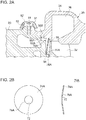
FIG. 2A is a cross-sectional view illustrating a structure around a fastening portion between the turbine housing and the bearing housing according to an embodiment.FIG. 2B is a diagram illustrating a configuration of the back plate inFIG. 2A . -
FIG. 3 is a cross-sectional view illustrating a structure around a fastening portion between a turbine housing and a bearing housing according to an embodiment. -
FIG. 4A is a cross-sectional view illustrating a structure around a fastening portion between the turbine housing and the bearing housing according to an embodiment.FIG. 4B is a diagram illustrating a configuration of the back plate inFIG. 4A . -
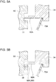
FIGs. 5A and 5B are each a cross-sectional view illustrating a configuration of a housing having a groove which receives a tip of a fin portion according to an embodiment. - Embodiments of the present invention will now be described in detail with reference to the accompanying drawings. It is intended, however, that unless particularly identified, dimensions, materials, shapes, relative positions and the like of components described in the embodiments shall be interpreted as illustrative only and not intended to limit the scope of the present invention.
-
FIG. 1 is a cross-sectional view illustrating an overall configuration of a turbocharger according to an embodiment. - As shown in the drawing, the
turbocharger 10 includes acompressor 20 for pressurizing intake air to an internal combustion engine (not depicted), and aturbine 30 driven by exhaust gas of the internal combustion engine. - The
compressor 20 includes acompressor wheel 22, and acompressor housing 24 disposed so as to cover thecompressor wheel 22. Intake air having entered from aninlet portion 26 of thecompressor 20 is compressed by thecompressor wheel 22, flows out from anoutlet portion 28 of thecompressor 20, and is guided to the internal combustion engine. - Furthermore, the
turbine 30 includes aturbine wheel 32, and aturbine housing 34 disposed so as to cover theturbine wheel 32. Theturbine wheel 32 is coupled to thecompressor wheel 22 via arotational shaft 33. Accordingly, theturbine wheel 32 rotates with thecompressor wheel 22. Exhaust gas having entered from an inlet portion (scroll portion) 36 of theturbine 30 performs work for theturbine wheel 32, and then is discharged from anoutlet portion 38 of theturbine 30. - Further, on the back-surface side of the
turbine wheel 32, aback plate 70 described below is provided. - A bearing
housing 50 is disposed between thecompressor housing 24 and theturbine housing 34. The bearinghousing 50 includesradial bearings thrust bearing 16. Therotational shaft 33 of theturbine wheel 32 is supported rotatably by the radial bearings (15A, 15B). Further, anoil deflector 18 is disposed on the side closer to thecompressor 20 than thethrust bearing 16, so as to block inflow of lubricant oil supplied to theradial bearings compressor 20. - The
turbine housing 34 and the bearinghousing 50 are fastened by afastening member 52. At this time, the position of theturbine housing 34 may be determined with respect to the bearinghousing 50, with a fin portion 60 disposed on one of theturbine housing 34 or the bearinghousing 50 being in contact with the other one of the housings (50, 34). The fin portion 60 will be described later. - In an illustrative embodiment depicted in
FIG. 1 , aflange 31 of theturbine housing 34 and aflange 53 of the bearinghousing 50 are fastened by aclamp 52. In another embodiment, theflange 31 of theturbine housing 34 and theflange 53 of the bearinghousing 50 are fastened by using a fastening bolt, instead of theclamp 52. Further, to suppress heat transfer via the fastening portion between the housings (34, 50), aheat insulator 51 may be provided between theflange 31 of theturbine housing 34 and theflange 53 of the bearinghousing 50. -
FIG. 2A is a cross-sectional view illustrating a structure around a fastening portion between the turbine housing and the bearing housing according to an embodiment.FIG. 2B is a diagram illustrating a configuration of theback plate 70A inFIG. 2A .FIG. 3 is a cross-sectional view illustrating a structure around a fastening portion between a turbine housing and a bearing housing according to an embodiment.FIG. 4A is a cross-sectional view illustrating a structure around a fastening portion between the turbine housing and the bearing housing according to an embodiment.FIG. 4B is a diagram illustrating a configuration of theback plate 70B inFIG. 4A . - In some embodiments, as shown in
FIGs. 2 to 4 , one of theturbine housing 34 or the bearinghousing 50 includes a fin portion 60 (60A, 60B) extending along the axial direction of therotational shaft 33. The fin portion 60 (60A, 60B) protrudes toward the other one of theturbine housing 34 or the bearinghousing 50. The tip of the fin portion 60 (60A, 60B) is in contact with the other one of theturbine housing 34 or the bearinghousing 50. - In an embodiment, the fin portion 60 (60A, 60B) is an annular fin disposed around the
rotational shaft 33. - In this case, the fin portion 60 is continuous in the circumferential direction, and it is possible to effectively suppress a leakage flow passing through the tip gap of the fin portion 60 in the radial direction.
- Further, a pair of
cavities cavity 80A is formed on the inner side of the fin portion 60 with respect to the radial direction, between theturbine housing 34 and the bearinghousing 50. Furthermore, thecavity 80B is formed on the outer side of the fin portion 60 with respect to the radial direction, between theturbine housing 34 and the bearinghousing 50. That is, the pair ofcavities rotational shaft 33. - In an illustrative embodiment shown in
FIGs. 2 to 4 , the fin portion 60 (60A, 60B) has a constant thickness. Nevertheless, the fin portion may have a thickness that decreases toward the tip in the radial direction. - Accordingly, by forming the
cavities turbine housing 34 to the bearinghousing 50, and reduce loss of thermal energy of theturbocharger 10. - Further, the fin portion 60 (60A, 60B) and the
cavities turbine housing 34 and the bearinghousing 50. In particular, in a case where the tip of the fin portion 60 (60A, 60B) is in contact with theturbine housing 34 or the bearinghousing 50 as described above, it is possible to achieve a high sealing effect generated by the fin portion 60. - Further, in an illustrative embodiment shown in
FIGs. 2A and4A , afin portion 60A is disposed on theturbine housing 34 so as to protrude toward the bearinghousing 50 in the axial direction. In contrast, in an illustrative embodiment shown inFIG. 3 , afin portion 60B is disposed on the bearinghousing 50 so as to protrude toward theturbine housing 34 in the axial direction. - In some embodiments, as shown in
FIGs. 2 to 4 , the back plate 70 (70A, 70B) is disposed on the back surface side of theturbine wheel 32. The first end of theback plate 70 is in contact with theturbine housing 34. The second end of theback plate 70 is in contact with the bearinghousing 50. Accordingly, theback plate 70 is held between theturbine housing 34 and the bearinghousing 50. - Accordingly, with the
back plate 70 being disposed on the back-surface side of theturbine wheel 32, it is possible to suppress heat transfer from theturbine housing 34 to the bearinghousing 50 even further, through the heat shield effect generated by theback plate 70. Furthermore, with both of the end portions of theback plate 70 being in contact with theturbine housing 34 and the bearinghousing 50 respectively to hold theback plate 70, it is possible to reduce the amount of heat transmitted to the bearinghousing 50 from theturbine housing 34 via theback plate 70, compared to a case where the turbine housing and the bearing housing nip the back plate. - In the embodiment shown in
FIGs. 2 to 4 , theturbine housing 34 includes a first steppedportion 35 for locking the first end of the back plate 70 (70A, 70B). Furthermore, the bearinghousing 50 includes a second steppedportion 54 for locking the second end of the back plate 70 (70A, 70B). - Accordingly, with both of the end portions of the
back plate 70 being locked by the first steppedportion 35 of theturbine housing 34 and the second steppedportion 54 of the bearinghousing 50, it is possible to hold theback plate 70 appropriately while suppressing heat transfer from theturbine housing 34 to the bearinghousing 50 via theback plate 70. - As shown in
FIG. 2B , in an embodiment, theback plate 70A has anopening 72 into which a cylindrical portion disposed on the bearinghousing 50 is to be fitted. On the radially outer side of theopening 72, theback plate 70A is disposed continuously in the circumferential direction. In a cross-section taken along the axial direction of therotational shaft 33, theback plate 70A extends obliquely with respect to the radial direction so as to become farther away from theturbine wheel 32 in the axial direction, from the first end of theback plate 70A on the side of the turbine housing 34 (radiallyouter portion 74A) toward the second end of theback plate 70A on the side of the bearing housing 50 (radiallyinner portion 76A), and theback plate 70A has a truncated cone shape as a whole. - As shown in
FIG. 2A andFIG. 3 , in theback plate 70A having the above configuration, the radiallyouter portion 74A is in contact with the first steppedportion 35 of theturbine housing 34, and the radiallyinner portion 76A is in contact with the second steppedportion 54 of the bearinghousing 50. Accordingly, theback plate 70A having a truncated cone shape is held between theturbine housing 34 and the bearinghousing 50. - In another embodiment, as shown in
FIG. 4B , theback plate 70B has anopening 72 into which a cylindrical portion disposed on the bearinghousing 50 is to be fitted. On the radially outer side of theopening 72, theback plate 70B is disposed continuously in the circumferential direction. Theback plate 70B includes a firstannular portion 74B positioned on the radially outer side, a secondannular portion 76B having theopening 72 and being positioned on the radially inner side, and amiddle flange portion 78B connecting the firstannular portion 74B and the secondannular portion 76B. In other words, theback plate 70B has a disc portion formed by themiddle flange portion 78B, and has annular protrudingportions - As shown in
FIG. 4A , theback plate 70B having the above configuration is held between theturbine housing 34 and the bearinghousing 50. In this state, the firstannular portion 74B of theback plate 70B extends in the axial direction along the wall surface of theturbine housing 34, and is in contact with the first steppedportion 35 of theturbine housing 34. Furthermore, the secondannular portion 76B extends in the axial direction along the wall surface of the bearinghousing 50, and is in contact with the second steppedportion 54 of the bearinghousing 50. - In the embodiments shown in
FIGs. 2 to 4 , the wall surface of the housing (34, 50) facing the tip of the fin portion 60 (60A, 60B) is a flat surface. However, in some other embodiments, a groove is formed on the housing (34, 50) facing the tip of the fin portion 60 (60A, 60B). -
FIGs. 5A and 5B are each a cross-sectional view illustrating a configuration of a housing having a groove which receives a tip of a fin portion according to an embodiment. - As shown in
FIGs. 5A and 5B , on the wall surface facing thefin portion 60A of the bearinghousing 50, agroove 56 which receives the tip of thefin portion 60A is formed. The tip of thefin portion 60A is in contact with the bottom surface of thegroove 56, so as to improve the sealing performance of thefin portion 60A. - In the illustrative embodiment shown in
FIG. 5B , aheat insulator 58A or a fillingmaterial 58B is disposed in thegroove 56 of the bearinghousing 50. - In a case where the
heat insulator 58A is disposed in thegroove 56, it is possible to suppress heat transfer to the bearinghousing 50 from theturbine housing 34 effectively. As theheat insulator 58A, a heat insulator (heat shield) having a thermal conductivity of not higher than 0.1W/m/K at normal temperature may be used, and for instance, theheat insulator 58A may be formed from a porous body made of a ceramic-based material or a silica-based material. - In a case where the filling
material 58B is disposed in thegroove 56, it is possible to prevent leakage of exhaust gas via the gap between thefin portion 60A and thegroove 56 with the fillingmaterial 58B, and to improve the sealing performance. - Further, a single member may serve as both of the
heat insulator 58A and the fillingmaterial 58B. - Further, in the embodiment shown in
FIGs. 5A and 5B , thefin portion 60A is disposed on theturbine housing 34 and thegroove 56 is disposed on the bearinghousing 50. Nevertheless, this example is not limitative. That is, thefin portion 60B may be disposed on the bearinghousing 50, and a groove that receives the tip of thefin portion 60B may be disposed on theturbine housing 34. In this case, theheat insulator 58A or the fillingmaterial 58B may be disposed in the groove of theturbine housing 34. - As described above, according to some embodiments of the present invention, the fin portion 60 (60A, 60B) is provided so as to extend along the axial direction of the
rotational shaft 33 from one of theturbine housing 34 or the bearinghousing 50 toward the other one of theturbine housing 34 or the bearinghousing 50, with thecavities turbine housing 34 to the bearinghousing 50, and reduce loss of thermal energy of theturbocharger 10. Further, the fin portion 60 and thecavities turbine housing 34 and the bearinghousing 50. - Embodiments of the present invention were described in detail above, but the present invention is not limited thereto, and various amendments and modifications may be implemented.
- Further, in the present specification, an expression of relative or absolute arrangement such as "in a direction", "along a direction", "parallel", "orthogonal", "centered", "concentric" and "coaxial" shall not be construed as indicating only the arrangement in a strict literal sense, but also includes a state where the arrangement is relatively displaced by a tolerance, or by an angle or a distance whereby it is possible to achieve the same function.
- For instance, an expression of an equal state such as "same" "equal" and "uniform" shall not be construed as indicating only the state in which the feature is strictly equal, but also includes a state in which there is a tolerance or a difference that can still achieve the same function.
- Further, for instance, an expression of a shape such as a rectangular shape or a cylindrical shape shall not be construed as only the geometrically strict shape, but also includes a shape with unevenness or chamfered corners within the range in which the same effect can be achieved.
- On the other hand, an expression such as "comprise", "include", "have", "contain" and "constitute" are not intended to be exclusive of other components.
-
- 10
- Turbocharger
- 15A
- Radial bearing
- 16
- Thrust bearing
- 18
- Oil deflector
- 20
- Compressor
- 22
- Compressor wheel
- 24
- Compressor housing
- 26
- Inlet portion
- 30
- Turbine
- 31
- Flange
- 32
- Turbine wheel
- 33
- Rotational shaft
- 34
- Turbine housing
- 35
- First stepped portion
- 50
- Bearing housing
- 51
- Heat insulator
- 52
- Fastening member
- 54
- Second stepped portion
- 56
- Groove
- 58A
- Heat insulator
- 58B
- Filling material
- 60, 60A, 60B
- Fin portion
- 70, 70A, 70B
- Back plate
- 72
- Opening
- 74A
- Radially outer portion
- 76A
- Radially inner portion
- 76B
- First annular portion
- 74B
- Second annular portion
- 78B
- Middle flange portion
- 80A, 80B
- Cavity
Claims (12)
- A turbocharger, comprising:a compressor wheel;a turbine wheel configured to rotate with the compressor wheel;a turbine housing disposed so as to cover the turbine wheel;a bearing supporting a rotational shaft of the turbine wheel rotatably; anda bearing housing accommodating the bearing,wherein one of the turbine housing or the bearing housing includes a fin portion protruding toward the other one of the turbine housing or the bearing housing so as to extend along an axial direction of the rotational shaft, andwherein, between the turbine housing and the bearing housing, a cavity is formed on each side of the fin portion with respect to a radial direction of the rotational shaft.
- The turbocharger according to claim 1,
wherein the fin portion includes a tip being in contact with the other one of the turbine housing or the bearing housing. - The turbocharger according to claim 1 or 2,
further comprising a fastening portion configured to fasten the turbine housing and the bearing housing,
wherein the fastening portion is configured to apply a fastening force in the axial direction to the turbine housing and the bearing housing so that a tip of the fin portion makes contact with the other one of the turbine housing or the bearing housing. - The turbocharger according to any one of claims 1 to 3,
wherein the other one of the turbine housing or the bearing housing includes a groove which receives a tip of the fin portion. - The turbocharger according to claim 4,
wherein the tip of the fin portion is in contact with a bottom surface of the groove. - The turbocharger according to claim 4 or 5,
further comprising a heat insulator disposed inside the groove. - The turbocharger according to any one of claims 4 to 6,
further comprising a filling material disposed inside the groove. - The turbocharger according to any one of claims 1 to 7,
further comprising a back plate disposed on a back-surface side of the turbine wheel,
wherein the back plate includes a first end and a second end with respect to the radial direction, and the back plate is held between the turbine housing and the bearing housing so that the first end is in contact with the turbine housing and the second end is in contact with the other one of the bearing housing. - The turbocharger according to claim 8,
wherein the turbine housing includes a first stepped portion for locking the first end of the back plate, and
wherein the bearing housing includes a second stepped portion for locking the second end of the back plate. - The turbocharger according to claim 8 or 9,
wherein the back plate extends obliquely with respect to the radial direction from the first end toward the second end of the back plate, in a cross section along the axial direction. - The turbocharger according to claim 8 or 9,
wherein the back plate includes:a first annular portion including the first end and extending in the axial direction along a wall surface of the turbine housing;a second annular portion including the second end and extending in the axial direction along a wall surface of the bearing housing; anda middle flange portion disposed between the first annular portion and the second annular portion so as to connect the first annular portion and the second annular portion. - The turbocharger according to any one of claims 1 to 11,
wherein the fin portion is an annular fin disposed around the rotational shaft.
Applications Claiming Priority (2)
| Application Number | Priority Date | Filing Date | Title |
|---|---|---|---|
| JP2016240770A JP6684698B2 (en) | 2016-12-12 | 2016-12-12 | Turbocharger |
| PCT/JP2017/035252 WO2018110032A1 (en) | 2016-12-12 | 2017-09-28 | Turbocharger |
Publications (3)
| Publication Number | Publication Date |
|---|---|
| EP3470648A1 true EP3470648A1 (en) | 2019-04-17 |
| EP3470648A4 EP3470648A4 (en) | 2019-12-25 |
| EP3470648B1 EP3470648B1 (en) | 2020-12-23 |
Family
ID=62558329
Family Applications (1)
| Application Number | Title | Priority Date | Filing Date |
|---|---|---|---|
| EP17880022.3A Active EP3470648B1 (en) | 2016-12-12 | 2017-09-28 | Turbocharger |
Country Status (5)
| Country | Link |
|---|---|
| US (1) | US10954816B2 (en) |
| EP (1) | EP3470648B1 (en) |
| JP (1) | JP6684698B2 (en) |
| CN (1) | CN109477420B (en) |
| WO (1) | WO2018110032A1 (en) |
Families Citing this family (4)
| Publication number | Priority date | Publication date | Assignee | Title |
|---|---|---|---|---|
| WO2019087231A1 (en) * | 2017-10-30 | 2019-05-09 | 三菱重工エンジン&ターボチャージャ株式会社 | Turbocharger |
| WO2021140562A1 (en) | 2020-01-07 | 2021-07-15 | 三菱重工エンジン&ターボチャージャ株式会社 | Turbine housing and turbocharger |
| WO2021199308A1 (en) * | 2020-03-31 | 2021-10-07 | 三菱重工エンジン&ターボチャージャ株式会社 | Turbocharger |
| US12540565B2 (en) * | 2023-02-24 | 2026-02-03 | Garrett Transportation I Inc. | Turbomachine with unitary housing member having chamber with plurality of internal braces |
Family Cites Families (38)
| Publication number | Priority date | Publication date | Assignee | Title |
|---|---|---|---|---|
| US3928963A (en) * | 1974-11-04 | 1975-12-30 | Gen Motors Corp | Cast in place gas turbine containment ring and method of manufacture |
| DE2823261C2 (en) * | 1978-05-27 | 1985-05-23 | Robert Bosch Gmbh, 7000 Stuttgart | Electric machine |
| JPS56138421A (en) * | 1980-04-01 | 1981-10-29 | Toyota Motor Corp | Conjoining structure of turbosupercharger |
| EP0646699B1 (en) * | 1993-09-03 | 1998-04-22 | Asea Brown Boveri Ag | Method for adapting the radial turbine of a turbocharger on an internal combustion engine |
| US6464268B1 (en) * | 2000-07-14 | 2002-10-15 | Cummins Inc. | High strength radial flange coupling |
| JP2003227344A (en) * | 2001-11-28 | 2003-08-15 | Hitachi Ltd | Turbocharger |
| DE10256418A1 (en) * | 2002-12-02 | 2004-06-09 | Abb Turbo Systems Ag | Exhaust turbine housing |
| EP1426563A1 (en) * | 2002-12-03 | 2004-06-09 | BorgWarner Inc. | Turbocharger with ceramic or metallic seal between the turbine and the bearing casing |
| DE202005009491U1 (en) * | 2005-06-16 | 2005-08-25 | Borgwarner Inc., Auburn Hills | Turbocharger rotor bearing arrangement for use in road vehicle internal combustion engine has disk sealing device with spring disk and heat insulating disk |
| US8784076B2 (en) | 2006-03-14 | 2014-07-22 | Borgwarner Inc. | Disk spring for a turbocharger |
| US7559199B2 (en) * | 2006-09-22 | 2009-07-14 | Honeywell International Inc. | Variable-nozzle cartridge for a turbocharger |
| JP4755071B2 (en) * | 2006-11-20 | 2011-08-24 | 三菱重工業株式会社 | Exhaust turbocharger |
| JP4885118B2 (en) * | 2007-12-21 | 2012-02-29 | 三菱重工業株式会社 | Variable displacement exhaust turbocharger with variable nozzle mechanism |
| JP2010138885A (en) * | 2008-12-15 | 2010-06-24 | Toyota Motor Corp | Turbocharger |
| DE102009058411A1 (en) * | 2009-12-16 | 2011-06-22 | BorgWarner Inc., Mich. | turbocharger |
| JP5402682B2 (en) * | 2010-01-29 | 2014-01-29 | 株式会社Ihi | Turbocharger sealing device |
| DE102010015272A1 (en) * | 2010-04-15 | 2011-10-20 | Bosch Mahle Turbo Systems Gmbh & Co. Kg | loader |
| US9988939B2 (en) * | 2010-09-13 | 2018-06-05 | Ihi Corporation | Fixed vane-type turbocharger |
| DE102010043198B4 (en) * | 2010-11-01 | 2022-06-02 | Abb Schweiz Ag | Burst protection for an exhaust gas turbocharger |
| JP2012117483A (en) * | 2010-12-02 | 2012-06-21 | Ihi Corp | Stationary blade type turbocharger |
| JP5832090B2 (en) * | 2010-12-15 | 2015-12-16 | 三菱重工業株式会社 | Turbocharger housing seal structure |
| US8763393B2 (en) * | 2011-08-08 | 2014-07-01 | Honeywell International Inc. | Sealing arrangement between a variable-nozzle assembly and a turbine housing of a turbocharger |
| KR20130017196A (en) | 2011-08-10 | 2013-02-20 | 삼성전자주식회사 | Washing machine |
| DE102011114060A1 (en) * | 2011-09-22 | 2013-03-28 | Ihi Charging Systems International Gmbh | Heat shield for an exhaust gas turbocharger and arrangement of a heat shield between two housing parts of an exhaust gas turbocharger |
| CN202417693U (en) * | 2012-01-18 | 2012-09-05 | 潍坊富源增压器有限公司 | Turbocharger |
| US9353637B2 (en) * | 2012-05-11 | 2016-05-31 | Honeywell International Inc. | Turbine exhaust housing |
| JP5966786B2 (en) * | 2012-09-10 | 2016-08-10 | 株式会社Ihi | Variable capacity turbocharger |
| JP6040727B2 (en) * | 2012-11-21 | 2016-12-07 | 株式会社Ihi | Turbocharger |
| WO2014168803A1 (en) * | 2013-04-12 | 2014-10-16 | Borgwarner Inc. | Exhaust-gas turbocharger |
| ES2935815T3 (en) * | 2013-09-06 | 2023-03-10 | MTU Aero Engines AG | (Dis)assembly of a gas turbine rotor, in particular front |
| DE102013111562A1 (en) * | 2013-10-21 | 2015-04-23 | Ihi Charging Systems International Gmbh | turbocharger |
| US9988977B2 (en) * | 2014-10-14 | 2018-06-05 | Borgwarner Inc. | Heat shield with centering features |
| JP5816356B2 (en) * | 2014-10-31 | 2015-11-18 | 三菱重工業株式会社 | Turbocharger housing seal structure |
| US10683870B2 (en) * | 2015-03-24 | 2020-06-16 | Mitsubishi Heavy Industries Engine & Turbocharger, Ltd. | Impeller cover, rotary machine, and impeller cover manufacturing method |
| US20160326893A1 (en) * | 2015-05-07 | 2016-11-10 | Icr Turbine Engine Corporation | Ceramic turbine volute |
| US10161265B2 (en) * | 2015-09-10 | 2018-12-25 | Mitsubishi Heavy Industries Engine & Turbocharger, Ltd. | Bearing device for turbocharger, and turbocharger |
| WO2018109933A1 (en) * | 2016-12-16 | 2018-06-21 | 三菱重工エンジン&ターボチャージャ株式会社 | Turbine housing, exhaust turbine, and turbocharger |
| DE102017121316A1 (en) * | 2017-09-14 | 2019-03-14 | Man Diesel & Turbo Se | turbocharger |
-
2016
- 2016-12-12 JP JP2016240770A patent/JP6684698B2/en active Active
-
2017
- 2017-09-28 CN CN201780043216.8A patent/CN109477420B/en active Active
- 2017-09-28 WO PCT/JP2017/035252 patent/WO2018110032A1/en not_active Ceased
- 2017-09-28 EP EP17880022.3A patent/EP3470648B1/en active Active
- 2017-09-28 US US16/311,285 patent/US10954816B2/en active Active
Also Published As
| Publication number | Publication date |
|---|---|
| EP3470648B1 (en) | 2020-12-23 |
| EP3470648A4 (en) | 2019-12-25 |
| WO2018110032A1 (en) | 2018-06-21 |
| US20190234237A1 (en) | 2019-08-01 |
| JP6684698B2 (en) | 2020-04-22 |
| CN109477420B (en) | 2021-04-02 |
| US10954816B2 (en) | 2021-03-23 |
| JP2018096267A (en) | 2018-06-21 |
| CN109477420A (en) | 2019-03-15 |
Similar Documents
| Publication | Publication Date | Title |
|---|---|---|
| KR101989548B1 (en) | Turbocharger bearing housing with integrated heat shield | |
| US10677287B2 (en) | Bearing structure and turbocharger | |
| EP3470648B1 (en) | Turbocharger | |
| CN107208543A (en) | Turbocharger | |
| US11199201B2 (en) | Impeller back surface cooling structure and supercharger | |
| KR20100091259A (en) | Housing fastening method | |
| JP2010229925A (en) | Turbine shroud | |
| WO2016051531A1 (en) | Turbine | |
| KR102554216B1 (en) | Nozzle ring for turbocharger | |
| US10781704B2 (en) | Turbine and turbocharge | |
| US10907541B2 (en) | Turbine housing, exhaust turbine, and turbocharger | |
| US10753367B2 (en) | Mounting structure and turbocharger | |
| US11118501B2 (en) | Turbine and turbocharger including the same | |
| US11713709B2 (en) | Nozzle device and exhaust turbocharger | |
| US11300140B2 (en) | Compressor wheel and supercharger | |
| US11319964B2 (en) | Turbocharger and bearing housing therefor | |
| EP3418579A1 (en) | Compressor impeller | |
| CN106150675A (en) | Turbocharger and automobile | |
| JP2011149390A (en) | Supercharger |
Legal Events
| Date | Code | Title | Description |
|---|---|---|---|
| STAA | Information on the status of an ep patent application or granted ep patent |
Free format text: STATUS: THE INTERNATIONAL PUBLICATION HAS BEEN MADE |
|
| PUAI | Public reference made under article 153(3) epc to a published international application that has entered the european phase |
Free format text: ORIGINAL CODE: 0009012 |
|
| STAA | Information on the status of an ep patent application or granted ep patent |
Free format text: STATUS: REQUEST FOR EXAMINATION WAS MADE |
|
| 17P | Request for examination filed |
Effective date: 20190111 |
|
| AK | Designated contracting states |
Kind code of ref document: A1 Designated state(s): AL AT BE BG CH CY CZ DE DK EE ES FI FR GB GR HR HU IE IS IT LI LT LU LV MC MK MT NL NO PL PT RO RS SE SI SK SM TR |
|
| AX | Request for extension of the european patent |
Extension state: BA ME |
|
| A4 | Supplementary search report drawn up and despatched |
Effective date: 20191121 |
|
| RIC1 | Information provided on ipc code assigned before grant |
Ipc: F01D 25/14 20060101ALI20191115BHEP Ipc: F01D 25/24 20060101ALI20191115BHEP Ipc: F02B 39/00 20060101AFI20191115BHEP Ipc: F02C 6/12 20060101ALI20191115BHEP Ipc: F02B 37/00 20060101ALI20191115BHEP |
|
| DAV | Request for validation of the european patent (deleted) | ||
| DAX | Request for extension of the european patent (deleted) | ||
| GRAP | Despatch of communication of intention to grant a patent |
Free format text: ORIGINAL CODE: EPIDOSNIGR1 |
|
| STAA | Information on the status of an ep patent application or granted ep patent |
Free format text: STATUS: GRANT OF PATENT IS INTENDED |
|
| RIC1 | Information provided on ipc code assigned before grant |
Ipc: F01D 25/24 20060101ALI20200626BHEP Ipc: F02B 39/00 20060101AFI20200626BHEP Ipc: F01D 5/04 20060101ALI20200626BHEP Ipc: F02B 37/00 20060101ALI20200626BHEP Ipc: F01D 25/14 20060101ALI20200626BHEP Ipc: F02C 6/12 20060101ALI20200626BHEP |
|
| INTG | Intention to grant announced |
Effective date: 20200722 |
|
| GRAS | Grant fee paid |
Free format text: ORIGINAL CODE: EPIDOSNIGR3 |
|
| GRAA | (expected) grant |
Free format text: ORIGINAL CODE: 0009210 |
|
| STAA | Information on the status of an ep patent application or granted ep patent |
Free format text: STATUS: THE PATENT HAS BEEN GRANTED |
|
| AK | Designated contracting states |
Kind code of ref document: B1 Designated state(s): AL AT BE BG CH CY CZ DE DK EE ES FI FR GB GR HR HU IE IS IT LI LT LU LV MC MK MT NL NO PL PT RO RS SE SI SK SM TR |
|
| REG | Reference to a national code |
Ref country code: GB Ref legal event code: FG4D |
|
| REG | Reference to a national code |
Ref country code: DE Ref legal event code: R096 Ref document number: 602017030257 Country of ref document: DE |
|
| REG | Reference to a national code |
Ref country code: AT Ref legal event code: REF Ref document number: 1347932 Country of ref document: AT Kind code of ref document: T Effective date: 20210115 |
|
| REG | Reference to a national code |
Ref country code: IE Ref legal event code: FG4D |
|
| PG25 | Lapsed in a contracting state [announced via postgrant information from national office to epo] |
Ref country code: FI Free format text: LAPSE BECAUSE OF FAILURE TO SUBMIT A TRANSLATION OF THE DESCRIPTION OR TO PAY THE FEE WITHIN THE PRESCRIBED TIME-LIMIT Effective date: 20201223 Ref country code: RS Free format text: LAPSE BECAUSE OF FAILURE TO SUBMIT A TRANSLATION OF THE DESCRIPTION OR TO PAY THE FEE WITHIN THE PRESCRIBED TIME-LIMIT Effective date: 20201223 Ref country code: NO Free format text: LAPSE BECAUSE OF FAILURE TO SUBMIT A TRANSLATION OF THE DESCRIPTION OR TO PAY THE FEE WITHIN THE PRESCRIBED TIME-LIMIT Effective date: 20210323 Ref country code: GR Free format text: LAPSE BECAUSE OF FAILURE TO SUBMIT A TRANSLATION OF THE DESCRIPTION OR TO PAY THE FEE WITHIN THE PRESCRIBED TIME-LIMIT Effective date: 20210324 |
|
| REG | Reference to a national code |
Ref country code: AT Ref legal event code: MK05 Ref document number: 1347932 Country of ref document: AT Kind code of ref document: T Effective date: 20201223 |
|
| REG | Reference to a national code |
Ref country code: NL Ref legal event code: MP Effective date: 20201223 |
|
| PG25 | Lapsed in a contracting state [announced via postgrant information from national office to epo] |
Ref country code: BG Free format text: LAPSE BECAUSE OF FAILURE TO SUBMIT A TRANSLATION OF THE DESCRIPTION OR TO PAY THE FEE WITHIN THE PRESCRIBED TIME-LIMIT Effective date: 20210323 Ref country code: LV Free format text: LAPSE BECAUSE OF FAILURE TO SUBMIT A TRANSLATION OF THE DESCRIPTION OR TO PAY THE FEE WITHIN THE PRESCRIBED TIME-LIMIT Effective date: 20201223 Ref country code: SE Free format text: LAPSE BECAUSE OF FAILURE TO SUBMIT A TRANSLATION OF THE DESCRIPTION OR TO PAY THE FEE WITHIN THE PRESCRIBED TIME-LIMIT Effective date: 20201223 |
|
| PG25 | Lapsed in a contracting state [announced via postgrant information from national office to epo] |
Ref country code: HR Free format text: LAPSE BECAUSE OF FAILURE TO SUBMIT A TRANSLATION OF THE DESCRIPTION OR TO PAY THE FEE WITHIN THE PRESCRIBED TIME-LIMIT Effective date: 20201223 Ref country code: NL Free format text: LAPSE BECAUSE OF FAILURE TO SUBMIT A TRANSLATION OF THE DESCRIPTION OR TO PAY THE FEE WITHIN THE PRESCRIBED TIME-LIMIT Effective date: 20201223 |
|
| REG | Reference to a national code |
Ref country code: LT Ref legal event code: MG9D |
|
| PG25 | Lapsed in a contracting state [announced via postgrant information from national office to epo] |
Ref country code: SM Free format text: LAPSE BECAUSE OF FAILURE TO SUBMIT A TRANSLATION OF THE DESCRIPTION OR TO PAY THE FEE WITHIN THE PRESCRIBED TIME-LIMIT Effective date: 20201223 Ref country code: EE Free format text: LAPSE BECAUSE OF FAILURE TO SUBMIT A TRANSLATION OF THE DESCRIPTION OR TO PAY THE FEE WITHIN THE PRESCRIBED TIME-LIMIT Effective date: 20201223 Ref country code: CZ Free format text: LAPSE BECAUSE OF FAILURE TO SUBMIT A TRANSLATION OF THE DESCRIPTION OR TO PAY THE FEE WITHIN THE PRESCRIBED TIME-LIMIT Effective date: 20201223 Ref country code: LT Free format text: LAPSE BECAUSE OF FAILURE TO SUBMIT A TRANSLATION OF THE DESCRIPTION OR TO PAY THE FEE WITHIN THE PRESCRIBED TIME-LIMIT Effective date: 20201223 Ref country code: RO Free format text: LAPSE BECAUSE OF FAILURE TO SUBMIT A TRANSLATION OF THE DESCRIPTION OR TO PAY THE FEE WITHIN THE PRESCRIBED TIME-LIMIT Effective date: 20201223 Ref country code: PT Free format text: LAPSE BECAUSE OF FAILURE TO SUBMIT A TRANSLATION OF THE DESCRIPTION OR TO PAY THE FEE WITHIN THE PRESCRIBED TIME-LIMIT Effective date: 20210423 Ref country code: SK Free format text: LAPSE BECAUSE OF FAILURE TO SUBMIT A TRANSLATION OF THE DESCRIPTION OR TO PAY THE FEE WITHIN THE PRESCRIBED TIME-LIMIT Effective date: 20201223 |
|
| PG25 | Lapsed in a contracting state [announced via postgrant information from national office to epo] |
Ref country code: AT Free format text: LAPSE BECAUSE OF FAILURE TO SUBMIT A TRANSLATION OF THE DESCRIPTION OR TO PAY THE FEE WITHIN THE PRESCRIBED TIME-LIMIT Effective date: 20201223 Ref country code: PL Free format text: LAPSE BECAUSE OF FAILURE TO SUBMIT A TRANSLATION OF THE DESCRIPTION OR TO PAY THE FEE WITHIN THE PRESCRIBED TIME-LIMIT Effective date: 20201223 |
|
| REG | Reference to a national code |
Ref country code: DE Ref legal event code: R097 Ref document number: 602017030257 Country of ref document: DE |
|
| PG25 | Lapsed in a contracting state [announced via postgrant information from national office to epo] |
Ref country code: IS Free format text: LAPSE BECAUSE OF FAILURE TO SUBMIT A TRANSLATION OF THE DESCRIPTION OR TO PAY THE FEE WITHIN THE PRESCRIBED TIME-LIMIT Effective date: 20210423 |
|
| PG25 | Lapsed in a contracting state [announced via postgrant information from national office to epo] |
Ref country code: IT Free format text: LAPSE BECAUSE OF FAILURE TO SUBMIT A TRANSLATION OF THE DESCRIPTION OR TO PAY THE FEE WITHIN THE PRESCRIBED TIME-LIMIT Effective date: 20201223 Ref country code: AL Free format text: LAPSE BECAUSE OF FAILURE TO SUBMIT A TRANSLATION OF THE DESCRIPTION OR TO PAY THE FEE WITHIN THE PRESCRIBED TIME-LIMIT Effective date: 20201223 |
|
| PLBE | No opposition filed within time limit |
Free format text: ORIGINAL CODE: 0009261 |
|
| STAA | Information on the status of an ep patent application or granted ep patent |
Free format text: STATUS: NO OPPOSITION FILED WITHIN TIME LIMIT |
|
| PG25 | Lapsed in a contracting state [announced via postgrant information from national office to epo] |
Ref country code: DK Free format text: LAPSE BECAUSE OF FAILURE TO SUBMIT A TRANSLATION OF THE DESCRIPTION OR TO PAY THE FEE WITHIN THE PRESCRIBED TIME-LIMIT Effective date: 20201223 |
|
| 26N | No opposition filed |
Effective date: 20210924 |
|
| PG25 | Lapsed in a contracting state [announced via postgrant information from national office to epo] |
Ref country code: ES Free format text: LAPSE BECAUSE OF FAILURE TO SUBMIT A TRANSLATION OF THE DESCRIPTION OR TO PAY THE FEE WITHIN THE PRESCRIBED TIME-LIMIT Effective date: 20201223 |
|
| PG25 | Lapsed in a contracting state [announced via postgrant information from national office to epo] |
Ref country code: SI Free format text: LAPSE BECAUSE OF FAILURE TO SUBMIT A TRANSLATION OF THE DESCRIPTION OR TO PAY THE FEE WITHIN THE PRESCRIBED TIME-LIMIT Effective date: 20201223 |
|
| REG | Reference to a national code |
Ref country code: CH Ref legal event code: PL |
|
| REG | Reference to a national code |
Ref country code: BE Ref legal event code: MM Effective date: 20210930 |
|
| PG25 | Lapsed in a contracting state [announced via postgrant information from national office to epo] |
Ref country code: IS Free format text: LAPSE BECAUSE OF FAILURE TO SUBMIT A TRANSLATION OF THE DESCRIPTION OR TO PAY THE FEE WITHIN THE PRESCRIBED TIME-LIMIT Effective date: 20210423 Ref country code: MC Free format text: LAPSE BECAUSE OF FAILURE TO SUBMIT A TRANSLATION OF THE DESCRIPTION OR TO PAY THE FEE WITHIN THE PRESCRIBED TIME-LIMIT Effective date: 20201223 |
|
| PG25 | Lapsed in a contracting state [announced via postgrant information from national office to epo] |
Ref country code: LU Free format text: LAPSE BECAUSE OF NON-PAYMENT OF DUE FEES Effective date: 20210928 Ref country code: IE Free format text: LAPSE BECAUSE OF NON-PAYMENT OF DUE FEES Effective date: 20210928 Ref country code: BE Free format text: LAPSE BECAUSE OF NON-PAYMENT OF DUE FEES Effective date: 20210930 |
|
| PG25 | Lapsed in a contracting state [announced via postgrant information from national office to epo] |
Ref country code: LI Free format text: LAPSE BECAUSE OF NON-PAYMENT OF DUE FEES Effective date: 20210930 Ref country code: CH Free format text: LAPSE BECAUSE OF NON-PAYMENT OF DUE FEES Effective date: 20210930 |
|
| PG25 | Lapsed in a contracting state [announced via postgrant information from national office to epo] |
Ref country code: CY Free format text: LAPSE BECAUSE OF FAILURE TO SUBMIT A TRANSLATION OF THE DESCRIPTION OR TO PAY THE FEE WITHIN THE PRESCRIBED TIME-LIMIT Effective date: 20201223 |
|
| PG25 | Lapsed in a contracting state [announced via postgrant information from national office to epo] |
Ref country code: HU Free format text: LAPSE BECAUSE OF FAILURE TO SUBMIT A TRANSLATION OF THE DESCRIPTION OR TO PAY THE FEE WITHIN THE PRESCRIBED TIME-LIMIT; INVALID AB INITIO Effective date: 20170928 |
|
| PG25 | Lapsed in a contracting state [announced via postgrant information from national office to epo] |
Ref country code: MK Free format text: LAPSE BECAUSE OF FAILURE TO SUBMIT A TRANSLATION OF THE DESCRIPTION OR TO PAY THE FEE WITHIN THE PRESCRIBED TIME-LIMIT Effective date: 20201223 |
|
| PG25 | Lapsed in a contracting state [announced via postgrant information from national office to epo] |
Ref country code: TR Free format text: LAPSE BECAUSE OF FAILURE TO SUBMIT A TRANSLATION OF THE DESCRIPTION OR TO PAY THE FEE WITHIN THE PRESCRIBED TIME-LIMIT Effective date: 20201223 |
|
| PG25 | Lapsed in a contracting state [announced via postgrant information from national office to epo] |
Ref country code: MT Free format text: LAPSE BECAUSE OF FAILURE TO SUBMIT A TRANSLATION OF THE DESCRIPTION OR TO PAY THE FEE WITHIN THE PRESCRIBED TIME-LIMIT Effective date: 20201223 |
|
| PGFP | Annual fee paid to national office [announced via postgrant information from national office to epo] |
Ref country code: DE Payment date: 20250805 Year of fee payment: 9 |
|
| PGFP | Annual fee paid to national office [announced via postgrant information from national office to epo] |
Ref country code: GB Payment date: 20250807 Year of fee payment: 9 |
|
| PGFP | Annual fee paid to national office [announced via postgrant information from national office to epo] |
Ref country code: FR Payment date: 20250808 Year of fee payment: 9 |