EP3470613A1 - Lamella, solar shading device, multiple glazing glass sheet, facade element and method for producing a lamella and use of a retroreflective coating on a lamella - Google Patents
Lamella, solar shading device, multiple glazing glass sheet, facade element and method for producing a lamella and use of a retroreflective coating on a lamella Download PDFInfo
- Publication number
- EP3470613A1 EP3470613A1 EP17001700.8A EP17001700A EP3470613A1 EP 3470613 A1 EP3470613 A1 EP 3470613A1 EP 17001700 A EP17001700 A EP 17001700A EP 3470613 A1 EP3470613 A1 EP 3470613A1
- Authority
- EP
- European Patent Office
- Prior art keywords
- retroreflective
- layer
- lamella
- elements
- shading device
- Prior art date
- Legal status (The legal status is an assumption and is not a legal conclusion. Google has not performed a legal analysis and makes no representation as to the accuracy of the status listed.)
- Withdrawn
Links
Images

Classifications
-
- E—FIXED CONSTRUCTIONS
- E06—DOORS, WINDOWS, SHUTTERS, OR ROLLER BLINDS IN GENERAL; LADDERS
- E06B—FIXED OR MOVABLE CLOSURES FOR OPENINGS IN BUILDINGS, VEHICLES, FENCES OR LIKE ENCLOSURES IN GENERAL, e.g. DOORS, WINDOWS, BLINDS, GATES
- E06B9/00—Screening or protective devices for wall or similar openings, with or without operating or securing mechanisms; Closures of similar construction
- E06B9/24—Screens or other constructions affording protection against light, especially against sunshine; Similar screens for privacy or appearance; Slat blinds
- E06B9/26—Lamellar or like blinds, e.g. venetian blinds
- E06B9/38—Other details
- E06B9/386—Details of lamellae
-
- E—FIXED CONSTRUCTIONS
- E06—DOORS, WINDOWS, SHUTTERS, OR ROLLER BLINDS IN GENERAL; LADDERS
- E06B—FIXED OR MOVABLE CLOSURES FOR OPENINGS IN BUILDINGS, VEHICLES, FENCES OR LIKE ENCLOSURES IN GENERAL, e.g. DOORS, WINDOWS, BLINDS, GATES
- E06B9/00—Screening or protective devices for wall or similar openings, with or without operating or securing mechanisms; Closures of similar construction
- E06B9/24—Screens or other constructions affording protection against light, especially against sunshine; Similar screens for privacy or appearance; Slat blinds
- E06B9/26—Lamellar or like blinds, e.g. venetian blinds
- E06B9/264—Combinations of lamellar blinds with roller shutters, screen windows, windows, or double panes; Lamellar blinds with special devices
-
- E—FIXED CONSTRUCTIONS
- E06—DOORS, WINDOWS, SHUTTERS, OR ROLLER BLINDS IN GENERAL; LADDERS
- E06B—FIXED OR MOVABLE CLOSURES FOR OPENINGS IN BUILDINGS, VEHICLES, FENCES OR LIKE ENCLOSURES IN GENERAL, e.g. DOORS, WINDOWS, BLINDS, GATES
- E06B9/00—Screening or protective devices for wall or similar openings, with or without operating or securing mechanisms; Closures of similar construction
- E06B9/24—Screens or other constructions affording protection against light, especially against sunshine; Similar screens for privacy or appearance; Slat blinds
- E06B2009/2417—Light path control; means to control reflection
-
- E—FIXED CONSTRUCTIONS
- E06—DOORS, WINDOWS, SHUTTERS, OR ROLLER BLINDS IN GENERAL; LADDERS
- E06B—FIXED OR MOVABLE CLOSURES FOR OPENINGS IN BUILDINGS, VEHICLES, FENCES OR LIKE ENCLOSURES IN GENERAL, e.g. DOORS, WINDOWS, BLINDS, GATES
- E06B9/00—Screening or protective devices for wall or similar openings, with or without operating or securing mechanisms; Closures of similar construction
- E06B9/24—Screens or other constructions affording protection against light, especially against sunshine; Similar screens for privacy or appearance; Slat blinds
- E06B9/26—Lamellar or like blinds, e.g. venetian blinds
- E06B9/264—Combinations of lamellar blinds with roller shutters, screen windows, windows, or double panes; Lamellar blinds with special devices
- E06B2009/2643—Screens between double windows
Definitions
- the invention relates to a lamella for a shading device, in particular for a Venetian blind, a shading device, a multi-pane glass, a facade element, a method for producing a lamella and a use of a retroreflective layer on a lamella.
- Such slats and shading devices in particular venetian blinds are known from the prior art and practice in different embodiments.
- Shading devices such as venetian blinds serve, for example, to prevent direct irradiation of high-energy sunlight through a pane into a room, without, however, completely preventing the passage of scattered light through the pane and sealing it in a non-transparent manner.
- Visibility, sun protection and glare protection on and around buildings is a central factor for life and health Quality of work in buildings.
- Venetian blinds are the wishes for as much daylight and visual contact to the outside, a glare-free workplace with air and surface temperatures in the comfort zone and a minimal effort for heating and air conditioning to meet hardly.
- Direct sunlight into the room can cause unwanted heating of the room.
- the entry of scattered light in the room is desirable because it contributes to the lighting of the room and thus to a good sense of space.
- the object of the invention is therefore to provide a lamella, a shading device, a multiple glass pane, a facade element and a method for producing a lamella and a use of the type mentioned, which improve the performance characteristics and in particular the reflection properties of fins and shading devices equipped therewith.
- a lamella for a shading device which has a retroreflective layer on at least one side.
- the retroreflective layer may be applied to a main body of the lamella.
- the retroreflective layer on at least one side of the lamella makes it possible to reflect light beams which impinge on a point of the layer on the at least one side of the lamella at different angles of incidence against their direction of irradiation from the lamella. This results in the lamella having retroreflective properties due to the retroreflective layer within a certain angular range, which may be comparatively large.
- the at least one side of the lamella on which the retroreflective layer is arranged or applied may be, for example, a, in particular curved, top of the lamella. It can be advantageous if the retroreflective layer completely covers the at least one side of the lamella.
- a lamella is created with the blade according to the invention, which is more tolerant with respect to the angular position between a radiation source, for example, the sun, and the lamella than previously known slats.
- the lamella can tolerate or take into account different or changing azimuth angles of the sun better than lamellae known from practice to date, without losing their effect.
- the lamella according to the invention makes it possible to retroreflect the light striking the lamella, even when it is changing Sun position without changing the orientation of the slat would be required. This effect can occur in a large Einstrahlwinkel Scheme.
- the orientation of the slat according to the invention must therefore be adapted less frequently or not at all to the position of the sun in order to prevent unwanted irradiation of light by a shading device equipped with the slat, in particular by a venetian blind.
- the blade provided with such a retroreflective layer also has the advantage that it can be produced on conventional machines and also processed. Elaborate folding and / or embossing of the blade, as they are known in practice in part, to influence the reflection properties of the previous slats, can be avoided. Such pleats and / or embossments of the sipe may cause difficulties in processing the sipes and in producing the sipe louvers equipped with such sipes. These disadvantages can be avoided with the blade according to the invention. This is especially true if the retroreflective layer has a layer thickness that is only a few millimeters or even less than one millimeter, that is, for example, in the micrometer range.
- Shading devices for which the blade according to the invention is suitable for example, venetian blinds or slatted curtains.
- the retroreflective layer may include or contain retroreflective elements or consist of such retroreflective elements.
- the retroreflective elements can be made of a transparent Material, for example made of glass or plastic.
- the retroreflective layer comprises a carrier material layer in which the retroreflective elements are embedded.
- a material for the substrate layer for example, paint, paint and / or film can be used.
- a carrier material it is also possible first of all to use liquid plastic which, after application, cures to the at least one side of the lamella and then, together with the retroreflective elements, forms the retroreflective layer on the at least one side of the lamella.
- the retroreflective layer is a retroreflective lacquer layer.
- so-called retroreflective varnish can be used, which is applied to the at least one side, in particular of a base body, of the lamella and forms the retroreflecting layer there.
- a reflective color layer for example of retroreflective color, can be applied to the at least one side of the lamella.
- the retroreflective layer may be formed from a retroreflective sheeting.
- the retroreflective sheeting may be adhered to and / or laminated to the at least one side of the sipe.
- the retroreflective elements can be arranged or contained in or on the lacquer.
- the retroreflective elements may be contained or disposed in or on the ink. The retroreflective elements can then comparatively simple and uncomplicated in applying the Color or the paint get into their position of use on the at least one side of the lamella.
- a retroreflective sheeting as a retroreflective layer on the at least one side of the lamella is characterized by its ease of handling.
- retroreflective elements may be included in the retroreflective sheeting.
- the film then acts as a carrier material for the retroreflective elements.
- the retroreflective sheeting can be tailored according to the dimensions of the side of the lamella to be coated, in particular cut to size, and then glued or laminated onto the at least one side of the lamella.
- the retroreflective layer can also consist of retroreflective elements. Then no carrier material such as paint, paint or foil is used, in which the retroreflective elements are embedded.
- the retroreflective elements may preferably be made of a transparent material.
- the most suitable materials are glass and plastic.
- the retroreflective elements may be isotropic with respect to their retroreflective properties.
- the retroreflective elements are therefore retroreflective regardless of their orientation. This can be advantageous since the retroreflective elements can then be arranged particularly easily and without regard to their orientation in or on or on the layer. Regardless of their orientation, the retroreflective elements can then develop their retroreflective properties due to their isotropic nature.
- the retroreflective elements consist of a transparent material, for example of glass and / or plastic, whose refractive index is isotropic.
- Such isotropic material has a computational index that is independent of the location or orientation of the retroreflective element to a radiation source. In this way, regardless of their position in, on or on the layer, the retroreflective bodies can exhibit their retroreflective effect. This too can simplify manufacture of the lamella, in particular application of the layer.
- the retroreflective elements may be retroreflective bodies, which are preferably made of a transparent material, such as glass.
- retroreflective bodies in the form of spheres, beads and / or prisms can be used. Particularly preferred as prisms tetrahedral prisms can be used.
- the retroreflective layer on the at least one side of the lamella may be particularly thin if the retroreflective elements are retroreflective microbodies, in particular spheres, beads and / or prisms, preferably tetrahedral prisms.
- microelements may be understood to be those retroreflective elements in which a dimension relevant to their retroreflective properties is smaller than one millimeter, that is to say in the micrometer range.
- a relevant dimension may be the diameter of the spherical microbody. This diameter of the spherical and retroreflective microbody may then be less than one millimeter.
- glass beads or glass beads as Retroflexionsdeem which have a diameter which is smaller than 0.3 millimeters.
- a shading device with at least one blade according to one of claims 1 to 5 is proposed.
- the shading device is designed as a venetian blind.
- the at least one lamella is pivotable or rotatable about its longitudinal axis.
- the at least one lamella can be arranged to be pivotable or rotatable, for example, on a carrier element of the shading device.
- a multi-pane glass with the means and features of the directed to a multiple glass pane independent claim is proposed.
- a shading device in particular a venetian blind, according to one of claims 6 or 7 is arranged, the at least one lamella after a of claims 1 to 5.
- the multiple glass pane can be designed as an insulating glass pane.
- Such multiple glass panes may also be referred to as laminated glass panes.
- the slats of the shading device in particular the venetian blind, can be arranged rotatably or pivotably on an element, in particular on a frame or spacer frame, the multi-pane glass or on a carrier element of the shading device, in particular the Venetian blind.
- a facade element in particular a composite façade element is proposed, which has the means and features of the directed on a facade element independent claim.
- a façade element with at least two panes is proposed to solve the problem thus having a disc space arranged between the panes or formed in which a shading device, in particular a Venetian blind according to one of claims 6 or 7 is arranged, the at least one lamella after a of claims 1 to 5.
- the slats of the shading device in particular the venetian blind, rotatable or pivotable on an element, in particular on a frame or spacer frame, the composite facade element or on a support member of the shading device, in particular the venetian blind arranged his.
- a method for producing a lamella in particular a lamella according to one of claims 1 to 5 is proposed, in which at least one side, in particular of a base body, the lamella is provided with a retroreflective layer.
- this side of the lamella can be coated with the retroreflective layer.
- the side to which the retroreflective layer is applied may be a, preferably curved, top of the lamella.
- the retroreflective layer can be applied to a main body of the lamella and cover there at least partially or preferably over the entire surface of at least one side of the lamella.
- retroreflective elements may be applied to the at least one side as a retroreflective layer.
- a retroreflective layer can also be a carrier material layer, preferably embedded therein, retroreflective applied to the at least one side.
- a retroreflective lacquer layer, a retroreflective ink layer or a retroreflective sheeting with preferably retroreflective elements located therein is applied to the at least one side of the fin as a retroreflective layer.
- the retroreflective lacquer layer and the retroreflective colored layer can be brushed, brushed, sprayed or even poured on. Also, the order by immersing the blade in a corresponding paint or dye bath is possible.
- the retroreflective layer can be applied in the form of a retroreflective sheeting on the at least one side of the lamella.
- the retroreflective sheeting may be adhered and / or laminated to the at least one side, for example.
- the paint, the paint and / or the film can each serve as a carrier material, in which the retroreflective elements are embedded in the position of use.
- retroreflective elements are applied as a retroreflective layer on the at least one side of the blade. This can optionally be done without a carrier material such as paint, paint or foil.
- the retroreflective layer may comprise retroreflective elements made of a transparent material, in particular of glass and / or plastic.
- the properties which the retroreflective elements may have are described in detail above.
- the retroreflective layer used may be a substrate layer having retroreflective elements embedded therein.
- a retroreflective lacquer layer a retroreflective ink layer and / or a retroreflective sheeting may be used as the layer.
- the retroreflective layer consists of such retroreflective elements.
- retroreflection can be understood to mean the reflection of a radiation incident on a surface, which largely independent of the orientation of the surface to the radiation source and largely in the direction back to the radiation source.
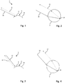
- FIGS. 1 and 3 and FIGS. 5 and 6 show lamellae designated as a whole by 1 for a shade device designed as a louvered blind 2.
- the lamellae 1 shown in the figures are provided on at least one side 3, here on their curved top 3, with a retroreflective layer 4.
- the layer 4 is applied to a main body la of the blade 1 and covers the side 3 of the blade 1 at least partially, in the present case even completely.
- the retroreflective layer 4 has the effect that light rays which are emitted at different angles of incidence (cf. Fig. 1 to 4 ) impinge on a point of the layer 4, are retroreflected contrary to their direction of irradiation. In this way, light incident on the lamella 1 can be retroreflected largely independently of the orientation of the lamella 1 to the light source in the direction of the light source.
- the retroreflective layer 4 may be a retroreflective resist layer, a retroreflective ink layer, and / or a retroreflective sheeting.
- the retroreflective layer 4 includes a plurality of retroreflective elements 5, one of which is in the FIGS. 2 and 4 is shown very schematically.
- the retroreflective elements 5 are made of a transparent material. Preferably, transparent glass is used here.
- the layer 4 comprises a carrier material in which the retroreflective elements 5 are embedded.
- the carrier material may be, for example, paint, paint, foil or, initially, liquid and hardening plastic by order.
- retroreflective elements 5 are isotropic with regard to their reflection property. Thus, they have no preferred direction in which they have to be aligned or oriented in or on the layer 4 in order to develop their retroreflective properties.
- the retroreflective elements 5 are made of a transparent material, here made of a glass whose refractive index is isotropic.
- the material, here the glass, from which the retroreflective elements 5 each consist has a non-directional and direction-independent refractive index. Regardless of the orientation of the retroreflective elements 5 in, on or on the layer 4 so the refractive index of the material is always the same.
- the FIGS. 2 and 4 further clarify that the retroreflective elements 5 are retroreflective bodies.
- the retroreflective bodies have a spherical shape and can therefore be referred to as spheres or as beads.
- retroreflective bodies which have a prismatic geometry. Tetrahedral prisms may be particularly suitable as retroreflective elements 5.
- the retroreflective elements 5 are present as retroreflective microbodies because of their dimensions in the micrometer range. In the in the FIGS. 2 and 4 In the embodiment shown, these are retroreflective bodies which have a dimension relevant to retroreflection, which is smaller than one millimeter and lies in the micrometer range.
- the in the FIGS. 1 and 3 shown slats 1 are used on a Venetian blind 2, as for example in the FIGS. 5 and 6 are shown.
- the slats are 1 in the FIGS. 5 and 6 shown Venetian blinds 2 each pivotable about its longitudinal axis or rotatably arranged. This in order to change the orientation of the slats 1 in the venetian blind 2, if necessary.
- the slats 1 can be arranged pivotably or rotatably on a support element of the slatted blind 2 or else on a support element of a multiple glass pane 6 or a facade element, in particular on a composite facade element.
- FIGS. 5 and 6 now show a multiple glass pane 6, which can also be used as a facade element or composite facade element.
- the in the FIGS. 5 and 6 shown multiple glass pane 6 has a total of two panes 7 and arranged between the panes 7 disc space 8.
- the Venetian blind 2 is arranged with the slats 1.
- the multi-pane glass 6 has a head box 9 for receiving the blind 2.
- the at least one side 3 of the lamella 1 is provided with the retroreflective layer 4. This can preferably be done over the entire surface.
- a retroreflective lacquer layer, a retroreflective ink layer and / or a retroreflective sheeting with retroreflective elements 5 may be applied as the retroreflective layer 4.
- a retroreflective sheeting may be glued or laminated to the at least one side 3.
- the retroreflective layer 4 is used on at least one side 3 of the lamella 1 of the venetian blind 2.
- FIG. 1 shows how a first light beam 10 impinges on the retroreflective layer 4 on the lamella 1 at a first angle.
- the dashed and provided with the reference numeral 11 arrow shows the reflection of the light beam 10. It is noteworthy that the reflection due to the retroreflective layer 4 on the lamella 1 takes place counter to the direction of irradiation of the light beam 10. In this case, the light beam 10 can be reflected in itself or offset to the layer 4.
- a second light beam 12 impinges on the retroreflective layer 4 of the lamella 1 with an unchanged angle of the lamella 1 at a different angle of incidence than the first light beam 10, a retroreflection of the light beam 12 also occurs here on the retroreflective layer 4 of the lamella 1.
- the light beam 12 is thrown back against the irradiation direction of the light beam 12 by the retroreflective layer 4 on the side 3 of the lamella 1 via the reflected light beam 13 shown in dashed lines.
- retroreflection can mean that one on the Retroreflective layer 4 incident light beam is reflected or reflected almost parallel or parallel offset to its direction of irradiation counter to its irradiation direction of the retroreflective layer 4 of the lamella 1.
- FIGS. 2 and 4 Now illustrate the beam path of the light beams 10 and 12 and the reflected light beams 11 and 13 in the spherical retroreflective elements 5, which are arranged in the layer 4 of the lamella 1.
- the light beam 10 enters the retroreflective element 5
- the light beam 10 is refracted.
- total reflection occurs so that the light beam 10 in the form of the reflected light beam 11 exits the retroreflective element 5 counter to the irradiation direction of the light beam 10.
- the light beam 12 occurs at a different angle of incidence to the retroreflective body 5 disposed within the retroreflective layer 4, retroreflection of the light beam 12 in and on the retroreflective body 5 also occurs here according to the previously described principle Retroreflexionselement 5 first broken, then totally reflected at the back 14 of the retroreflective element 5 and then exits as a dashed line shown light beam 13 opposite to the direction of irradiation of the light beam 12 from the retroreflective element 5 again.
- the lamella 1 has its orientation to the light source, which emits the light beams 10 and 12, not changed.
- the slat 1 is proposed. This has a retroreflective layer 4 on at least one side 3, so that light incident on the retroreflecting layer 4 is retroreflected at least in a certain angular range, independently of the orientation of the lamella 1 to a light source.
Landscapes
- Engineering & Computer Science (AREA)
- Structural Engineering (AREA)
- Architecture (AREA)
- Civil Engineering (AREA)
- Blinds (AREA)
Abstract
Zur Verbesserung der Reflexionseigenschaften von Lamellen und Verschattungsvorrichtungen wie Lamellenjalousien wird unter anderem die Lamelle (1) vorgeschlagen. Diese weist an zumindest einer Seite 3 eine retroreflektierende Schicht (4) auf, so dass auf die retroreflektierende Schicht (4) auftreffendes Licht zumindest in einem bestimmten Winkelbereich unabhängig von der Ausrichtung der Lamelle (1) zu einer Lichtquelle retroreflektiert wirdTo improve the reflective properties of slats and shading devices such as venetian blinds, inter alia, the slat (1) is proposed. This has a retroreflective layer (4) on at least one side 3, so that light incident on the retroreflecting layer (4) is retroreflected at least in a certain angular range, irrespective of the orientation of the lamella (1) to a light source
Description
Die Erfindung betrifft eine Lamelle für eine Verschattungsvorrichtung, insbesondere für eine Lamellenjalousie, eine Verschattungsvorrichtung, eine Mehrfachglasscheibe, ein Fassadenenlement, ein Verfahren zur Herstellung einer Lamelle sowie eine Verwendung einer retroreflektierenden Schicht an einer Lamelle.The invention relates to a lamella for a shading device, in particular for a Venetian blind, a shading device, a multi-pane glass, a facade element, a method for producing a lamella and a use of a retroreflective layer on a lamella.
Derartige Lamellen und Verschattungsvorrichtungen, insbesondere Lamellenjalousien sind aus dem Stand der Technik und der Praxis in unterschiedlichen Ausführungsformen bekannt. Verschattungsvorrichtungen wie Lamellenjalousien dienen zum Beispiel dazu, eine direkte Einstrahlung von hochenergetischem Sonnenlicht durch eine Scheibe in einen Raum zu verhindern, ohne jedoch den Durchtritt von Streulicht durch die Scheibe gänzlich zu verhindern und diese blickdicht zu verschließen.Such slats and shading devices, in particular venetian blinds are known from the prior art and practice in different embodiments. Shading devices such as venetian blinds serve, for example, to prevent direct irradiation of high-energy sunlight through a pane into a room, without, however, completely preventing the passage of scattered light through the pane and sealing it in a non-transparent manner.
Der Sicht-, Sonnen- und Blendschutz von und an Gebäuden ist ein zentraler Faktor für Lebens- und Arbeitsqualität in Gebäuden. Mit den bisher bekannten Lamellenjalousien sind die Wünsche nach möglichst viel Tageslicht und Sichtkontakt nach außen, ein blendfreier Arbeitsplatz mit Luft- und Oberflächentemperaturen im Wohlfühlbereich und ein minimaler Aufwand für Heizung und Klimatisierung bisher kaum zu erfüllen.Visibility, sun protection and glare protection on and around buildings is a central factor for life and health Quality of work in buildings. With the previously known Venetian blinds are the wishes for as much daylight and visual contact to the outside, a glare-free workplace with air and surface temperatures in the comfort zone and a minimal effort for heating and air conditioning to meet hardly.
Eine direkte Einstrahlung von Sonnenlicht in den Raum kann eine ungewünschte Aufheizung des Raums verursachen. Der Eintrag von Streulicht in den Raum ist jedoch erwünscht, da er zur Beleuchtung des Raums und damit zu einem guten Raumgefühl beiträgt.Direct sunlight into the room can cause unwanted heating of the room. The entry of scattered light in the room is desirable because it contributes to the lighting of the room and thus to a good sense of space.
Um eine direkte Einstrahlung von Sonnenlicht zu verhindern und auch eine Aufheizung der Lamellen zu vermeiden, ist es beispielsweise vorbekannt, Lamellen aus hochreflektierenden Metallbändern zu verwenden. Dabei werden auf die Lamelle auftreffende Lichtstrahlen nach dem Prinzip Einfallswinkel gleich Ausfallswinkel von den Oberfläche der Lamellen reflektiert.In order to prevent a direct irradiation of sunlight and to avoid heating of the slats, it is for example already known to use slats of highly reflective metal bands. In this case, light rays incident on the lamella are reflected by the surface of the lamellae according to the principle of angle of incidence equal to the angle of reflection.
Je nachdem, wie die Lamellen zur Sonne ausgerichtet ist, kann eine unerwünschte Einstrahlung von Sonnenlicht durch die Lamellenjalousie auftreten. Dies führt nicht nur zu einer Aufheizung des Raumes, sondern auch zu möglicherweise störenden Blendeffekten. Um die Einstrahlung von Sonnenlicht zu verhindern und Blendeffekte aufgrund von Reflexionen, die in den Raum gelenkt werden, zu vermeiden, kann es erforderlich sein, die Ausrichtung der Lamellen an den sich im Tagesverlauf verändernden Sonnenstand von Zeit zu Zeit anzupassen. Dies kann manuell oder automatisch durch eine Steuerung erfolgen und ist mit einem gewissen Aufwand verbunden.Depending on how the fins are aligned with the sun, unwanted sunlight may be transmitted through the venetian blinds. This not only leads to a heating of the room, but also to potentially disturbing glare effects. To prevent sunlight from entering and to avoid dazzling effects due to reflections being directed into the room, it may be necessary to adjust the orientation of the slats to the changing position of the sun from time to time. This can be done manually or automatically by a controller and is associated with a certain effort.
Je nach Sonnenstand ist es unter Umständen sogar notwendig, die Lamellen in eine nahezu vollständig geschlossene Stellung zu bringen, um eine direkte Einstrahlung von Sonnenlicht zu verhindern. Dies mit dem Nebeneffekt, dass dann auch kein Streulicht mehr in den Raum eingetragen werden kann.Depending on the position of the sun, it may even be necessary to bring the lamellae into an almost completely closed position in order to prevent a direct irradiation of sunlight. This with the side effect that then no stray light can be entered in the room.
Aufgabe der Erfindung ist es daher, eine Lamelle, eine Verschattungsvorrichtung, eine Mehrfachglasscheibe, ein Fassadenelement und ein Verfahren zur Herstellung einer Lamelle sowie eine Verwendung der eingangs genannten Art bereitzustellen, die die Gebrauchseigenschaften und insbesondere die Reflexionseigenschaften von Lamellen und damit ausgestatteten Verschattungsvorrichtungen verbessern.The object of the invention is therefore to provide a lamella, a shading device, a multiple glass pane, a facade element and a method for producing a lamella and a use of the type mentioned, which improve the performance characteristics and in particular the reflection properties of fins and shading devices equipped therewith.
Diese Aufgabe wird mit einer Lamelle der eingangs genannten Art gelöst, die die Mittel und Merkmale des unabhängigen, auf eine derartige Lamelle gerichteten Anspruchs aufweist. Zur Lösung der Aufgabe wird insbesondere eine Lamelle für eine Verschattungsvorrichtung vorgeschlagen, die an zumindest einer Seite eine retroreflektierende Schicht aufweist. Die retroreflektierende Schicht kann auf einen Grundkörper der Lamelle aufgetragen sein. Durch die retroreflektierende Schicht an zumindest einer Seite der Lamelle ist es möglich, Lichtstrahlen, die unter unterschiedlichen Einstrahlwinkeln auf einen Punkt der Schicht an der zumindest einen Seite der Lamelle auftreffen, entgegen ihrer Einstrahlungsrichtung von der Lamelle zu reflektieren. Dies führt dazu, dass die Lamelle innerhalb eines gewissen Winkelbereichs, der vergleichsweise groß sein kann, aufgrund der retroreflektierenden Schicht retroreflektierende Eigenschaften aufweist.This object is achieved with a lamella of the type mentioned, which has the means and features of independent, directed to such a lamella claim. To achieve the object, in particular a lamella for a shading device is proposed, which has a retroreflective layer on at least one side. The retroreflective layer may be applied to a main body of the lamella. The retroreflective layer on at least one side of the lamella makes it possible to reflect light beams which impinge on a point of the layer on the at least one side of the lamella at different angles of incidence against their direction of irradiation from the lamella. This results in the lamella having retroreflective properties due to the retroreflective layer within a certain angular range, which may be comparatively large.
Die zumindest eine Seite der Lamelle, an der die retroreflektierende Schicht angeordnet oder aufgetragen ist, kann zum Beispiel eine, insbesondere gewölbte, Oberseite der Lamelle sein. Vorteilhaft kann es sein, wenn die retroreflektierende Schicht die zumindest eine Seite der Lamelle vollflächig überdeckt.The at least one side of the lamella on which the retroreflective layer is arranged or applied, may be, for example, a, in particular curved, top of the lamella. It can be advantageous if the retroreflective layer completely covers the at least one side of the lamella.
Somit kann auf die Lamelle auftreffendes Sonnenlicht weitgehend unabhängig vom sich im Tagesverlauf verändernden Sonnenstand auch bei unveränderter Ausrichtung der Lamelle mit Hilfe der retroreflektierenden Schicht zurück in Richtung der Sonne reflektiert werden. Eine Einstrahlung von Sonnenlicht, das an der Lamelle reflektiert und in einen mit der Lamelle zu verschattenden Raum eingespiegelt wird, kann so vermieden werden. Da das von der retroreflektierenden Schicht retroreflektierte Sonnenlicht weitgehend zurück in Richtung Sonne - oder allgemein gesprochen zurück in Richtung Strahlungsquelle - reflektiert wird, kann eine unerwünschte Einstrahlung von reflektiertem Licht auf andere Gebäude oder Gebäudeteile mithilfe der erfindungsgemäßen Lamelle vermieden werden. Bei den bisher bekannten Lamellen besteht das Risiko, mit dem von der Lamelle reflektierten Licht andere Gebäude, Gebäudeteile oder auch Personen, insbesondere Verkehrsteilnehmer, zu treffen und gegebenenfalls zu blenden.As a result, sunlight striking the lamella can largely be reflected back into the direction of the sun, regardless of the position of the sun changing during the course of the day, even if the lamella is still aligned with the aid of the retroreflecting layer. An irradiation of sunlight, which is reflected at the lamella and reflected in a shaded with the lamella space can be avoided. As the retroreflective layer retroreflected by the retroreflective layer is largely reflected back toward the sun - or generally speaking back towards the radiation source - unwanted irradiation of reflected light to other buildings or parts of buildings using the blade according to the invention can be avoided. In the lamellae known hitherto, there is the risk of hitting other buildings, parts of buildings or even persons, in particular road users, with the light reflected by the lamella, and possibly dazzling it.
Insgesamt wird mit der erfindungsgemäßen Lamelle eine Lamelle geschaffen, die toleranter bezüglich der Winkelstellung zwischen einer Strahlungsquelle, zum Beispiel der Sonne, und der Lamelle als bisher bekannte Lamellen ist. Zudem kann die Lamelle aufgrund der retroreflektierenden Schicht auch unterschiedliche oder sich ändernde Azimut-Winkel der Sonne besser tolerieren bzw. berücksichtigen als bisher aus der Praxis bekannte Lamellen, ohne ihre Wirkung zu verlieren.Overall, a lamella is created with the blade according to the invention, which is more tolerant with respect to the angular position between a radiation source, for example, the sun, and the lamella than previously known slats. In addition, due to the retroreflective layer, the lamella can tolerate or take into account different or changing azimuth angles of the sun better than lamellae known from practice to date, without losing their effect.
Die erfindungsgemäße Lamelle ermöglicht eine Retroreflexion des auf die Lamelle treffenden Lichts auch bei sich änderndem Sonnenstand, ohne dass eine Änderung der Ausrichtung der Lamelle erforderlich wäre. Dieser Effekt kann in einem großen Einstrahlwinkelbereich auftreten. Im Vergleich zu vorbekannten Lamellen muss die Ausrichtung der erfindungsgemäßen Lamelle somit seltener oder sogar gar nicht an den Sonnenstand angepasst werden, um eine ungewünschte Einstrahlung von Licht durch eine mit der Lamelle ausgestattete Verschattungsvorrichtung, insbesondere durch eine Lamellenjalousie zu verhindern.The lamella according to the invention makes it possible to retroreflect the light striking the lamella, even when it is changing Sun position without changing the orientation of the slat would be required. This effect can occur in a large Einstrahlwinkelbereich. Compared to previously known slats, the orientation of the slat according to the invention must therefore be adapted less frequently or not at all to the position of the sun in order to prevent unwanted irradiation of light by a shading device equipped with the slat, in particular by a venetian blind.
Die mit einer derart retroreflektierenden Schicht ausgestattete Lamelle hat außerdem den Vorteil, dass sie auf gängigen Maschinen hergestellt und auch verarbeitet werden kann. Aufwändige Faltungen und/oder Prägungen der Lamelle, wie sie aus der Praxis zum Teil bekannt sind, um die Reflexionseigenschaften der bisherigen Lamellen zu beeinflussen, können so vermieden werden. Derartige Faltungen und/oder Prägungen der Lamelle können Schwierigkeiten bei der Verarbeitung der Lamellen und bei der Herstellung der mit derartigen Lamellen ausgestatteten Lamellenjalousien verursachen. Diese Nachteile können mit der erfindungsgemäßen Lamelle vermieden werden. Dies insbesondere dann, wenn die retroreflektierende Schicht eine Schichtdicke aufweist, die nur wenige Millimeter oder gar weniger als einen Millimeter beträgt, also zum Beispiel im Mikrometerbereich liegt.The blade provided with such a retroreflective layer also has the advantage that it can be produced on conventional machines and also processed. Elaborate folding and / or embossing of the blade, as they are known in practice in part, to influence the reflection properties of the previous slats, can be avoided. Such pleats and / or embossments of the sipe may cause difficulties in processing the sipes and in producing the sipe louvers equipped with such sipes. These disadvantages can be avoided with the blade according to the invention. This is especially true if the retroreflective layer has a layer thickness that is only a few millimeters or even less than one millimeter, that is, for example, in the micrometer range.
Verschattungsvorrichtungen, für die die erfindungsgemäße Lamelle geeignet ist, sind beispielsweise Lamellenjalousien oder auch Lamellenvorhänge.Shading devices for which the blade according to the invention is suitable, for example, venetian blinds or slatted curtains.
Die retroreflektierende Schicht kann Retroreflexionselemente aufweisen oder enthalten oder aus solchen Retroreflexionselementen bestehen. Die Retroreflexionselemente können aus einem transparenten Material, beispielsweise aus Glas oder Kunststoff bestehen.The retroreflective layer may include or contain retroreflective elements or consist of such retroreflective elements. The retroreflective elements can be made of a transparent Material, for example made of glass or plastic.
Vorteilhaft kann es sein, wenn die retroreflektierende Schicht eine Trägermaterialschicht umfasst, in das die Retroreflexionselemente eingebettet sind. Als Material für die Trägermaterialschicht können zum Beispiel Lack, Farbe und/oder Folie zum Einsatz kommen. Als Trägermaterial kann auch zunächst flüssiger Kunststoff verwendet werden, der nach Auftrag auf die zumindest eine Seite der Lamelle aushärtet und dann zusammen mit den Retroreflexionselementen die retroreflektierende Schicht an der zumindest einen Seite der Lamelle ausbildet.It can be advantageous if the retroreflective layer comprises a carrier material layer in which the retroreflective elements are embedded. As a material for the substrate layer, for example, paint, paint and / or film can be used. As a carrier material, it is also possible first of all to use liquid plastic which, after application, cures to the at least one side of the lamella and then, together with the retroreflective elements, forms the retroreflective layer on the at least one side of the lamella.
Vorteilhaft kann es sein, wenn die retroreflektierende Schicht eine retroreflektierende Lackschicht ist. Dabei kann sogenannter Retroreflexionslack eingesetzt werden, der auf die zumindest eine Seite, insbesondere eines Grundkörpers, der Lamelle aufgetragen wird und dort die retroreflektierende Schicht ausbildet. Alternativ kann auch eine reflektierende Farbschicht, beispielsweise aus Retroreflexionsfarbe, auf die zumindest eine Seite der Lamelle aufgebracht werden. Ferner kann die retroreflektierende Schicht von einer retroreflektierenden Folie gebildet werden. Die retroreflektierende Folie kann beispielsweise auf die zumindest eine Seite der Lamelle aufgeklebt und/oder auf diese Seite laminiert werden.It can be advantageous if the retroreflective layer is a retroreflective lacquer layer. In this case, so-called retroreflective varnish can be used, which is applied to the at least one side, in particular of a base body, of the lamella and forms the retroreflecting layer there. Alternatively, a reflective color layer, for example of retroreflective color, can be applied to the at least one side of the lamella. Further, the retroreflective layer may be formed from a retroreflective sheeting. For example, the retroreflective sheeting may be adhered to and / or laminated to the at least one side of the sipe.
Bei Verwendung einer retroreflektierenden Lackschicht als retroreflektierende Schicht können die Retroreflexionselemente in oder auf dem Lack angeordnet oder enthalten sein. Bei Verwendung einer retroreflektierenden Farbschicht als retroreflektierende Schicht können die Retroreflexionselemente in oder auf der Farbe enthalten oder angeordnet sein. Die Retroreflexionselemente können dann vergleichsweise einfach und unkompliziert beim Aufbringen der Farbe oder des Lacks in ihre Gebrauchsstellung an der zumindest einen Seite der Lamelle gelangen.When using a retroreflective lacquer layer as a retroreflective layer, the retroreflective elements can be arranged or contained in or on the lacquer. When using a retroreflective ink layer as a retroreflective layer, the retroreflective elements may be contained or disposed in or on the ink. The retroreflective elements can then comparatively simple and uncomplicated in applying the Color or the paint get into their position of use on the at least one side of the lamella.
Eine retroreflektierende Folie als retroreflektierende Schicht an der zumindest einen Seite der Lamelle zeichnet sich durch ihre einfache Handhabung aus. Hier können Retroreflexionselemente in der retroreflektierenden Folie enthalten sein. Die Folie fungiert dann als Trägermaterial für die Retroreflexionselmente. Die retroreflektierende Folie kann entsprechend den Abmessungen der zu beschichtenden Seite der Lamelle konfektioniert, insbesondere zugeschnitten, und anschließend auf die zumindest eine Seite der Lamelle aufgeklebt oder laminiert werden.A retroreflective sheeting as a retroreflective layer on the at least one side of the lamella is characterized by its ease of handling. Here retroreflective elements may be included in the retroreflective sheeting. The film then acts as a carrier material for the retroreflective elements. The retroreflective sheeting can be tailored according to the dimensions of the side of the lamella to be coated, in particular cut to size, and then glued or laminated onto the at least one side of the lamella.
Bei einer Variante kann die retroreflektierende Schicht auch aus Retroreflexionselementen bestehen. Dann kommt kein Trägermaterial wie Lack, Farbe oder Folie zum Einsatz, in das die Retroreflexionselemente eingebettet sind.In a variant, the retroreflective layer can also consist of retroreflective elements. Then no carrier material such as paint, paint or foil is used, in which the retroreflective elements are embedded.
Wie zuvor bereits ausgeführt, können die Retroreflexionselemente vorzugsweise aus einem transparenten Material bestehen. Als Material eignen sich vor allem Glas und Kunststoff. Vorteilhafterweise können die Retroreflexionselemente isotrop in Bezug auf ihre Retroreflexionseigenschaften sein. Somit sind die Retroreflexionselemente also unabhängig von ihrer Ausrichtung retroreflektierend. Dies kann von Vorteil sein, da die Retroreflexionselemente dann besonders einfach und ohne Beachtung ihrer Ausrichtung in oder an oder auf der Schicht angeordnet werden können. Unabhängig von ihrer Ausrichtung können die Retroreflexionselemente aufgrund ihrer diesbezüglichen Isotropie dann ihre retroreflektierenden Eigenschaften entfalten.As previously stated, the retroreflective elements may preferably be made of a transparent material. The most suitable materials are glass and plastic. Advantageously, the retroreflective elements may be isotropic with respect to their retroreflective properties. Thus, the retroreflective elements are therefore retroreflective regardless of their orientation. This can be advantageous since the retroreflective elements can then be arranged particularly easily and without regard to their orientation in or on or on the layer. Regardless of their orientation, the retroreflective elements can then develop their retroreflective properties due to their isotropic nature.
Besonders vorteilhaft kann es außerdem sein, wenn die Retroreflexionselemente aus einem transparenten Material, beispielsweise aus Glas und/oder Kunststoff bestehen, dessen Brechungsindex isotrop ist. Derartig isotropes Material hat einen Berechnungsindex, der unabhängig von der Lage oder Ausrichtung des Retroreflexionselements zu einer Strahlungsquelle ist. Auf diese Weise können die Retroreflexionskörper unabhängig von ihrer Lage in, an oder auf der Schicht ihre retroreflektierende Wirkung entfalten. Auch dies kann eine Herstellung der Lamelle, insbesondere eine Aufbringung der Schicht vereinfachen.It can also be particularly advantageous if the retroreflective elements consist of a transparent material, for example of glass and / or plastic, whose refractive index is isotropic. Such isotropic material has a computational index that is independent of the location or orientation of the retroreflective element to a radiation source. In this way, regardless of their position in, on or on the layer, the retroreflective bodies can exhibit their retroreflective effect. This too can simplify manufacture of the lamella, in particular application of the layer.
Die Retroreflexionselemente können Retroreflexionskörper sein, die bevorzugt aus einem transparenten Material, etwa aus Glas bestehen. Beispielsweise können Retroreflexionskörper in Form von Kugeln, Perlen und/oder Prismen verwendet werden. Besonders bevorzugt können als Prismen tetraedrische Prismen verwendet werden.The retroreflective elements may be retroreflective bodies, which are preferably made of a transparent material, such as glass. For example, retroreflective bodies in the form of spheres, beads and / or prisms can be used. Particularly preferred as prisms tetrahedral prisms can be used.
Die retroreflektierende Schicht an der zumindest einen Seite der Lamelle kann besonders dünn sein, wenn die Retroreflexionselemente retroreflektierende Mikrokörper, insbesondere Kugeln, Perlen und/oder Prismen, vorzugsweise tetraedrische Prismen sind. Als Mikrokörper können im Kontext der Erfindung solche Retroreflexionselemente verstanden werden, bei denen eine für ihre retroreflektierenden Eigenschaften relevante Abmessung kleiner als ein Millimeter ist, also im Mikrometerbereich liegt. Bei einem Retroreflexionselement, das in Form eines kugelförmigen Mikrokörpers vorliegt, kann eine relevanten Abmessung beispielsweise der Durchmesser des kugelförmigen Mikrokörpers sein. Dieser Durchmesser des kugelförmigen und retroreflektierenden Mikrokörpers kann dann kleiner als ein Millimeter sein. Besonders bevorzugt können beispielsweise Glasperlen oder Glaskugeln als Retroflexionskörper verwendet werden, die einen Durchmesser aufweisen, der kleiner als 0,3 Millimeter ist.The retroreflective layer on the at least one side of the lamella may be particularly thin if the retroreflective elements are retroreflective microbodies, in particular spheres, beads and / or prisms, preferably tetrahedral prisms. In the context of the invention, microelements may be understood to be those retroreflective elements in which a dimension relevant to their retroreflective properties is smaller than one millimeter, that is to say in the micrometer range. For example, in a retroreflective element that is in the form of a spherical microbody, a relevant dimension may be the diameter of the spherical microbody. This diameter of the spherical and retroreflective microbody may then be less than one millimeter. Particularly preferred, for example, glass beads or glass beads as Retroflexionskörper be used, which have a diameter which is smaller than 0.3 millimeters.
Zur Lösung der zuvor genannten Aufgabe wird auch eine Verschattungsvorrichtung mit wenigstens einer Lamelle nach einem der Ansprüche 1 bis 5 vorgeschlagen. Vorzugsweise ist die Verschattungsvorrichtung als Lamellenjalousie ausgebildet.To achieve the aforementioned object, a shading device with at least one blade according to one of
Besonders vorteilhaft kann es sein, wenn die wenigstens eine Lamelle dabei um ihre Längsachse schwenkbar oder drehbar ist. Dazu kann die wenigstens eine Lamelle beispielsweise an einem Trägerelement der Verschattungsvorrichtung schwenkbar oder drehbar angeordnet sein.It may be particularly advantageous if the at least one lamella is pivotable or rotatable about its longitudinal axis. For this purpose, the at least one lamella can be arranged to be pivotable or rotatable, for example, on a carrier element of the shading device.
Zur Lösung der Aufgabe wird auch eine Mehrfachglasscheibe mit den Mitteln und Merkmalen des auf eine Mehrfachglasscheibe gerichteten unabhängigen Anspruchs vorgeschlagen. Insbesondere wird zur Lösung der Aufgabe bei einer Mehrfachglasscheibe mit zumindest zwei Scheiben, zwischen denen ein Scheibenzwischenraum angeordnet ist, vorgeschlagen, dass in dem Scheibenzwischenraum eine Verschattungsvorrichtung, insbesondere eine Lamellenjalousie, nach einem der Ansprüche 6 oder 7 angeordnet ist, die wenigstens eine Lamelle nach einem der Ansprüche 1 bis 5 aufweist. Wenn die Lamellen in dem Scheibenzwischenraum angeordnet sind, ist die retroreflektierenden Schicht gut vor Beschädigungen und Verschmutzung geschützt, sodass sie ihre retroreflektierende Eigenschaft dauerhaft beibehalten kann.To achieve the object, a multi-pane glass with the means and features of the directed to a multiple glass pane independent claim is proposed. In particular, to solve the problem in a multiple glass pane having at least two panes, between which a space between the panes is arranged, proposed that in the space between the panes a shading device, in particular a venetian blind, according to one of
Besonders bevorzugt kann die Mehrfachglasscheibe dabei als Isolierglasscheibe ausgebildet sein. Solche Mehrfachglasscheiben können auch als Verbundglasscheiben bezeichnet werden. Um eine Ausrichtung der Lamellen im Scheibenzwischenraum zu erlauben, können die Lamellen der Verschattungsvorrichtung, insbesondere der Lamellenjalousie, drehbar oder schwenkbar an einem Element, insbesondere an einem Rahmen oder Abstandhalterrahmen, der Mehrfachglasscheibe oder an einem Trägerelement der Verschattungsvorrichtung, insbesondere der Lamellenjalousie, angeordnet sein.Particularly preferably, the multiple glass pane can be designed as an insulating glass pane. Such multiple glass panes may also be referred to as laminated glass panes. To align the slats in the To allow space between panes, the slats of the shading device, in particular the venetian blind, can be arranged rotatably or pivotably on an element, in particular on a frame or spacer frame, the multi-pane glass or on a carrier element of the shading device, in particular the Venetian blind.
Zur Lösung der Aufgabe wird ferner ein Fassadenelement, insbesondere ein Verbundfassadenelement, vorgeschlagen, das die Mittel und Merkmale des auf ein Fassadenelement gerichteten unabhängigen Anspruchs aufweist. Insbesondere wird zur Lösung der Aufgabe somit ein Fassadenelement mit zumindest zwei Scheiben vorgeschlagen, das einen zwischen den Scheiben angeordneten oder ausgebildeten Scheibenzwischenraum aufweist, in dem eine Verschattungsvorrichtung, insbesondere eine Lamellenjalousiem nach einem der Ansprüche 6 oder 7 angeordnet ist, die wenigstens eine Lamelle nach einem der Ansprüche 1 bis 5 aufweist.To achieve the object, a facade element, in particular a composite façade element is proposed, which has the means and features of the directed on a facade element independent claim. In particular, a façade element with at least two panes is proposed to solve the problem thus having a disc space arranged between the panes or formed in which a shading device, in particular a Venetian blind according to one of
Um eine Ausrichtung der Lamellen im Scheibenzwischenraum zu erlauben, können auch hier die Lamellen der Verschattungsvorrichtung, insbesondere der Lamellenjalousie, drehbar oder schwenkbar an einem Element, insbesondere an einem Rahmen oder Abstandhalterrahmen, des Verbundfassadenelements oder an einem Trägerelement der Verschattungsvorrichtung, insbesondere der Lamellenjalousie, angeordnet sein.In order to allow alignment of the slats in the space between the panes, the slats of the shading device, in particular the venetian blind, rotatable or pivotable on an element, in particular on a frame or spacer frame, the composite facade element or on a support member of the shading device, in particular the venetian blind arranged his.
Zur Lösung der eingangs genannten Aufgabe wird auch ein Verfahren zur Herstellung einer Lamelle, insbesondere einer Lamelle nach einem der Ansprüche 1 bis 5 vorgeschlagen, bei dem zumindest eine Seite, insbesondere eines Grundkörpers, der Lamelle mit einer retroreflektierenden Schicht versehen wird.To achieve the object mentioned above, a method for producing a lamella, in particular a lamella according to one of
Dabei kann diese Seite der Lamelle mit der retroreflektierenden Schicht beschichtet werden. Die Seite, auf die die retroreflektierende Schicht aufgebracht wird, kann eine, vorzugsweise gewölbte, Oberseite der Lamelle sein. Zu diesem Zweck kann die retroreflektierende Schicht auf einen Grundkörper der Lamelle aufgebracht werden und dort die zumindest eine Seite der Lamelle wenigstens teilweise oder vorzugsweise vollflächig überdecken.In this case, this side of the lamella can be coated with the retroreflective layer. The side to which the retroreflective layer is applied may be a, preferably curved, top of the lamella. For this purpose, the retroreflective layer can be applied to a main body of the lamella and cover there at least partially or preferably over the entire surface of at least one side of the lamella.
Bei einer Ausführungsform des Verfahrens können Retroreflexionselemente als retroreflektierende Schicht auf die zumindest eine Seite aufgebracht werden. Als retroreflektierende Schicht kann aber auch eine Trägermaterialschicht mit, vorzugsweise darin eingebetteten, Retroreflexionselementen auf die zumindest eine Seite aufgebracht werden.In one embodiment of the method, retroreflective elements may be applied to the at least one side as a retroreflective layer. As a retroreflective layer but can also be a carrier material layer, preferably embedded therein, retroreflective applied to the at least one side.
Besonders vorteilhaft kann es sein, wenn als retroreflektierende Schicht eine retroreflektierende Lackschicht, eine retroreflektierende Farbschicht oder eine retroreflektierende Folie mit vorzugsweise jeweils darin befindlichen Retroreflexionselementen auf die wenigstens eine Seite der Lamelle aufgebracht wird. Die retroreflektierende Lackschicht und die retroreflektierende Farbschicht können beispielsweise aufgestrichen, aufgepinselt, aufgesprüht oder auch aufgegossen werden. Auch der Auftrag mittels Eintauchens der Lamelle in ein entsprechendes Lack- oder Farbbad ist möglich.It may be particularly advantageous if a retroreflective lacquer layer, a retroreflective ink layer or a retroreflective sheeting with preferably retroreflective elements located therein is applied to the at least one side of the fin as a retroreflective layer. For example, the retroreflective lacquer layer and the retroreflective colored layer can be brushed, brushed, sprayed or even poured on. Also, the order by immersing the blade in a corresponding paint or dye bath is possible.
Besonders einfach kann die retroreflektierende Schicht in Form einer retroreflektierenden Folie auf die wenigstens eine Seite der Lamelle aufgebracht werden. Die retroreflektierende Folie kann auf die zumindest eine Seite zum Beispiel aufgeklebt und/oder laminiert werden.Particularly simply, the retroreflective layer can be applied in the form of a retroreflective sheeting on the at least one side of the lamella. The retroreflective sheeting may be adhered and / or laminated to the at least one side, for example.
Bei den zuvor beschriebenen Ausführungsformen des Verfahrens, können der Lack, die Farbe und/oder die Folie jeweils als Trägermaterial dienen, in das die Retroreflexionselemente in Gebrauchsstellung eingebettet sind.In the embodiments of the method described above, the paint, the paint and / or the film can each serve as a carrier material, in which the retroreflective elements are embedded in the position of use.
Es ist aber auch möglich, dass Retroreflexionselemente als retroreflektierende Schicht auf die zumindest eine Seite der Lamelle aufgebracht werden. Dies kann gegebenenfalls ohne Trägermaterial wie Lack, Farbe oder Folie erfolgen.But it is also possible that retroreflective elements are applied as a retroreflective layer on the at least one side of the blade. This can optionally be done without a carrier material such as paint, paint or foil.
Ferner wird zur Lösung der Aufgabe auch noch die Verwendung einer retroreflektierenden Schicht an zumindest einer Seite einer Lamelle vorgeschlagen. Dabei kann die retroreflektierende Schicht Retroreflexionselemente aus einem transparenten Material, insbesondere aus Glas und/oder Kunststoff aufweisen. Die Eigenschaften, die die Retroreflexionselemente aufweisen können, sind weiter oben ausführlich beschrieben.Furthermore, the use of a retroreflective layer on at least one side of a lamella is also proposed for achieving the object. In this case, the retroreflective layer may comprise retroreflective elements made of a transparent material, in particular of glass and / or plastic. The properties which the retroreflective elements may have are described in detail above.
Die verwendete retroreflektierende Schicht kann eine Trägermaterialschicht mit darin eingebetteten Retroreflexionselementen sein.The retroreflective layer used may be a substrate layer having retroreflective elements embedded therein.
Wie bereits zuvor ausgeführt, kann als Schicht eine retroreflektierende Lackschicht, eine retroreflektierende Farbschicht und/oder auch eine retroreflektierende Folie verwendet werden. Es ist aber auch möglich, dass die die retroreflektierende Schicht aus solchen Retroreflexionselementen besteht.As previously stated, a retroreflective lacquer layer, a retroreflective ink layer and / or a retroreflective sheeting may be used as the layer. But it is also possible that the retroreflective layer consists of such retroreflective elements.
Unter Retroreflexion kann im Kontext der Erfindung die Reflexion einer auf eine Fläche einfallenden Strahlung verstanden werden, die weitgehend unabhängig von der Ausrichtung der Fläche zur Strahlungsquelle und großteils in Richtung zurück zur Strahlungsquelle erfolgt.In the context of the invention, retroreflection can be understood to mean the reflection of a radiation incident on a surface, which largely independent of the orientation of the surface to the radiation source and largely in the direction back to the radiation source.
Die Erfindung wird nun anhand von Ausführungsbeispielen näher beschrieben, ist aber nicht auf diese Ausführungsbeispiele beschränkt. Es zeigen in stark schematisierter Darstellung:
- Fig. 1
- eine Seitenansicht einer erfindungsgemäßen Lamelle, mit einer auf einer Seite der Lamelle, nämlich ihrer gewölbten Oberseite, aufgebrachten retroreflektierenden Schicht, auf die Licht unter einem ersten Winkel einfällt und von dieser retroreflektiert wird,
- Fig. 2
- eine stark schematisierte Darstellung eines kugelförmigen Retroreflexionselements, das in der retroreflektierenden Schicht der in
Figur 1 - Fig. 3
- die in
Figur 1Vergleich zu Figur 1 anderen Winkel mit Licht bestrahlt wird und auch hier Retroreflexion auftritt, - Fig. 4
- eine weitere Darstellung des bereits in
Figur 2 - Fig. 5
- eine stark schematisierte, perspektivische Darstellung einer Mehrfachglasscheibe mit einer als Lamellenjalousie ausgebildeten Verschattungsvorrichtung, die in einem Scheibenzwischenraum der Mehrfachglasscheibe angeordnet ist und deren Lamellen solche Lamellen sind, wie sie in
den Figuren 1 und 3 dargestellt sind, sowie - Fig. 6
- eine weitere perspektivische Darstellung der in
Figur 5 dargestellten Mehrfachglasscheibe, mit einem Kopfkasten zur Aufnahme der Lamellenjalousie.
- Fig. 1
- a side view of a blade according to the invention, with a on one side of the lamella, namely its curved top, applied retroreflective layer, incident on the light at a first angle and is retroreflected by this,
- Fig. 2
- a highly schematic representation of a spherical retroreflective element, which in the retroreflective layer of in
FIG. 1 is shown, for illustrating the forming within the retroreflective element beam path, - Fig. 3
- in the
FIG. 1 in this illustration, the retroreflective layer of the blade under a comparison withFIG. 1 other angle is irradiated with light and also here retroreflection occurs, - Fig. 4
- another illustration of the already in
FIG. 2 illustrated retroreflective element, wherein here also a beam path is shown within the retroreflective element to illustrate the retroreflection, - Fig. 5
- a highly schematic, perspective view of a multiple glass pane with a Venetian blind formed shading device, which is arranged in a space between the panes of the multi-pane glass and the lamellae are such lamellae as in the
FIGS. 1 and 3 are shown, as well - Fig. 6
- a further perspective view of the multiple glass pane shown in Figure 5, with a head box for receiving the Venetian blind.
Die
Die retroreflektierende Schicht 4 hat den Effekt, dass Lichtstrahlen, die unter unterschiedlichen Einstrahlwinkeln (vgl.
Die retroreflektierende Schicht 4 kann eine retroreflektierende Lackschicht, eine retroreflektierende Farbschicht und/oder eine retroreflektierende Folie sein.The retroreflective layer 4 may be a retroreflective resist layer, a retroreflective ink layer, and / or a retroreflective sheeting.
Die retroreflektierende Schicht 4 enthält eine Vielzahl von Retroreflexionselementen 5, von denen jeweils eines in den
Die in den
Die
Die Retroreflexionselemente 5 liegen aufgrund ihrer Abemssungen im Mikrometerbereich als retroreflektierende Mikrokörper vor. In dem in den
Die in den
Die
Zur Herstellung der Lamelle 1, wie sie in den
Als retroreflektierende Schicht 4 kann, wie bereits zuvor erwähnt, eine retroreflektierende Lackschicht, eine retroreflektierende Farbschicht und/oder auch eine retroreflektierende Folie mit Retroreflexionselementen 5 aufgebracht werden. Eine retroreflektierende Folie kann auf die wenigstens eine Seite 3 geklebt oder laminiert werden. Somit wird also die retroreflektierende Schicht 4 an zumindest einer Seite 3 der Lamelle 1 der Lamellenjalousie 2 verwendet.As mentioned above, a retroreflective lacquer layer, a retroreflective ink layer and / or a retroreflective sheeting with
Die Funktionsweise der retroreflektierenden Schicht 4 wird anhand der
Obwohl ein zweiter Lichtstrahl 12 unter einem anderen Einstrahlwinkel auf die retroreflektierende Schicht 4 der Lamelle 1 bei unveränderter Ausrichtung der Lamelle 1 auftrifft als der erste Lichstrahl 10, tritt auch hier eine Retroreflexion des Lichtstrahls 12 an der retroreflektierenden Schicht 4 der Lamelle 1 auf. So wird der Lichtstrahl 12 über den strichliniert dargestellten reflektierten Lichtstrahl 13 entgegen der Einstrahlungsrichtung des Lichtstrahls 12 von der retroreflektierenden Schicht 4 an der Seite 3 der Lamelle 1 zurückgeworfen.Although a
Retroreflexion kann in diesem Fall bedeuten, dass ein auf die retroreflektierende Schicht 4 auftreffender Lichtstrahl in sich zurückgeworfen wird oder aber nahezu parallel oder parallel versetzt zu seiner Einstrahlungsrichtung entgegen seiner Einstrahlungsrichtung von der retroreflektierenden Schicht 4 der Lamelle 1 reflektiert wird.In this case, retroreflection can mean that one on the Retroreflective layer 4 incident light beam is reflected or reflected almost parallel or parallel offset to its direction of irradiation counter to its irradiation direction of the retroreflective layer 4 of the
Die
Obwohl der Lichtstrahl 12 unter einem anderen Einstrahlungswinkel auf die innerhalb der retroreflektierenden Schicht 4 angeordneten Retroreflexionskörper 5 auftritt, erfolgt auch hier nach dem zuvor beschriebenen Prinzip eine Retroreflexion des Lichtstrahls 12 in und an dem Retroreflexionskörper 5. Auch hier wird der Lichtstrahl 12 beim Eintritt in das Retroreflexionselement 5 zunächst gebrochen, anschließend an der Rückseite 14 des Retroreflexionselements 5 total reflektiert und tritt dann als hier strichliniert dargestellter Lichtstrahl 13 entgegen der Einstrahlungsrichtung des Lichtstrahls 12 aus dem Retroreflexionselement 5 wieder aus. Die Lamelle 1 hat dabei ihre Ausrichtung zu der Lichtquelle, die die Lichtstrahlen 10 und 12 abgibt, nicht verändert.Although the
Zur Verbesserung der Reflexionseigenschaften von Lamellen und Lamellenjalousien wird unter anderem die Lamelle 1 vorgeschlagen. Diese weist an zumindest einer Seite 3 eine retroreflektierende Schicht 4 auf, so dass auf die retroreflektierende Schicht 4 auftreffendes Licht zumindest in einem bestimmten Winkelbereich unabhängig von der Ausrichtung der Lamelle 1 zu einer Lichtquelle retroreflektiert wird.To improve the reflective properties of slats and venetian blinds, inter alia, the
- 11
- Lamellelamella
- 1a1a
- Grundkörper von 1Basic body of 1
- 22
- Verschattungsvorrichtung / LamellenjalousieShading device / Venetian blind
- 33
- Seite/Oberseite von 1Side / top of 1
- 44
- retroreflektierende Schichtretroreflective layer
- 55
- RetroreflexionselementRetroreflective element
- 66
- Mehrfachglasscheibe/FassadenelementMultiple-layer glass / facade element
- 77
- Scheibedisc
- 88th
- ScheibenzwischenraumDisk space
- 99
- Kopfkastenheadbox
- 1010
- Lichtstrahlbeam of light
- 1111
- reflektierter Lichtstrahlreflected light beam
- 1212
- Lichtstrahlbeam of light
- 1313
- reflektierter Lichtstrahlreflected light beam
- 1414
- Rückseite von 5Back of 5
Claims (15)
Priority Applications (1)
| Application Number | Priority Date | Filing Date | Title |
|---|---|---|---|
| EP17001700.8A EP3470613A1 (en) | 2017-10-13 | 2017-10-13 | Lamella, solar shading device, multiple glazing glass sheet, facade element and method for producing a lamella and use of a retroreflective coating on a lamella |
Applications Claiming Priority (1)
| Application Number | Priority Date | Filing Date | Title |
|---|---|---|---|
| EP17001700.8A EP3470613A1 (en) | 2017-10-13 | 2017-10-13 | Lamella, solar shading device, multiple glazing glass sheet, facade element and method for producing a lamella and use of a retroreflective coating on a lamella |
Publications (1)
| Publication Number | Publication Date |
|---|---|
| EP3470613A1 true EP3470613A1 (en) | 2019-04-17 |
Family
ID=60143463
Family Applications (1)
| Application Number | Title | Priority Date | Filing Date |
|---|---|---|---|
| EP17001700.8A Withdrawn EP3470613A1 (en) | 2017-10-13 | 2017-10-13 | Lamella, solar shading device, multiple glazing glass sheet, facade element and method for producing a lamella and use of a retroreflective coating on a lamella |
Country Status (1)
| Country | Link |
|---|---|
| EP (1) | EP3470613A1 (en) |
Citations (3)
| Publication number | Priority date | Publication date | Assignee | Title |
|---|---|---|---|---|
| DE10158620A1 (en) * | 2001-11-29 | 2003-07-10 | Prismen Gmbh & Co Kg | Daylight system with coated glass lamella for architectural applications has coated strips of flat glass arranged horizontally one above the other or vertically adjacent to each other |
| US20110310487A1 (en) * | 2010-06-16 | 2011-12-22 | Sony Corporation | Optical body, wall member, fitting, and solar shading device |
| WO2017130110A1 (en) * | 2016-01-26 | 2017-08-03 | Pellini S.P.A. | Double-glazing system with retroreflectivity properties |
-
2017
- 2017-10-13 EP EP17001700.8A patent/EP3470613A1/en not_active Withdrawn
Patent Citations (3)
| Publication number | Priority date | Publication date | Assignee | Title |
|---|---|---|---|---|
| DE10158620A1 (en) * | 2001-11-29 | 2003-07-10 | Prismen Gmbh & Co Kg | Daylight system with coated glass lamella for architectural applications has coated strips of flat glass arranged horizontally one above the other or vertically adjacent to each other |
| US20110310487A1 (en) * | 2010-06-16 | 2011-12-22 | Sony Corporation | Optical body, wall member, fitting, and solar shading device |
| WO2017130110A1 (en) * | 2016-01-26 | 2017-08-03 | Pellini S.P.A. | Double-glazing system with retroreflectivity properties |
Similar Documents
| Publication | Publication Date | Title |
|---|---|---|
| EP2041388B1 (en) | Sun protection device with angle-selective transmission properties | |
| EP0243912B1 (en) | Wall, window, and/or parapet element | |
| DE19700111C2 (en) | Sun protection device in the manner of a blind | |
| DE69514005T2 (en) | STEP LAMPS FOR DIRECT LIGHT RADIATION | |
| DE2732592A1 (en) | SCREEN FOR RADIANT ENERGY | |
| DE3612681A1 (en) | Glazing | |
| WO2003052232A1 (en) | Sun protection device | |
| DE19543811A1 (en) | Stepped lamella for light radiation control | |
| EP3470613A1 (en) | Lamella, solar shading device, multiple glazing glass sheet, facade element and method for producing a lamella and use of a retroreflective coating on a lamella | |
| DE19929141A1 (en) | Light deflecting lamellae consist of a partially toothed surface, where the top of the light lamellae concentrate retro-reflected rays | |
| EP0303107B1 (en) | Antiglare device | |
| EP0984131B1 (en) | Darkening and light-deflecting system | |
| EP2060734B1 (en) | Anti-dazzle device | |
| DE4140851A1 (en) | Sun-blind for protecting building from heating effect of solar radiation - has juxtaposed cells or channels separated by struts, with inner surfaces having larger reflective index for visible radiation than for solar and sky radiation components | |
| EP2538013A1 (en) | Angle-selective sunlight dimming on a building exterior | |
| DE10338378A1 (en) | Light transparent components for selective masking of light radiation in architectural applications, uses surface structures with linear prismatic structured surfaces | |
| DE102019206496B3 (en) | LIGHT PROTECTION DEVICE WITH HIGH-PRECISION OPTICS FOR GLARE-FREE LIGHT DEFLECTION | |
| AT525471B1 (en) | Film product for attachment to a building envelope to protect against bird strike | |
| WO2023147617A1 (en) | Film product for application to a building shell for protection against bird impact | |
| DE10128314C2 (en) | Device for influencing light radiation | |
| DE202021004109U1 (en) | Transparent composite structure with a micromirror device | |
| AT517822B1 (en) | Device for mixing colored light beams | |
| DE19929140A1 (en) | Toothed daylight panel has toothed upper side with teeth with one side facing sunlight, rear side facing room, inclination angle of sunlight side increasing from input to output cross-section | |
| WO2024200691A1 (en) | Optical element as sun protection for windows | |
| DE202011101237U1 (en) | Slat for sun protection and daylight steering systems |
Legal Events
| Date | Code | Title | Description |
|---|---|---|---|
| PUAI | Public reference made under article 153(3) epc to a published international application that has entered the european phase |
Free format text: ORIGINAL CODE: 0009012 |
|
| AK | Designated contracting states |
Kind code of ref document: A1 Designated state(s): AL AT BE BG CH CY CZ DE DK EE ES FI FR GB GR HR HU IE IS IT LI LT LU LV MC MK MT NL NO PL PT RO RS SE SI SK SM TR |
|
| AX | Request for extension of the european patent |
Extension state: BA ME |
|
| STAA | Information on the status of an ep patent application or granted ep patent |
Free format text: STATUS: THE APPLICATION HAS BEEN WITHDRAWN |
|
| 18W | Application withdrawn |
Effective date: 20190522 |