EP3470543A1 - Coated component and method of preparing a coated component - Google Patents
Coated component and method of preparing a coated component Download PDFInfo
- Publication number
- EP3470543A1 EP3470543A1 EP18198444.4A EP18198444A EP3470543A1 EP 3470543 A1 EP3470543 A1 EP 3470543A1 EP 18198444 A EP18198444 A EP 18198444A EP 3470543 A1 EP3470543 A1 EP 3470543A1
- Authority
- EP
- European Patent Office
- Prior art keywords
- coating
- diffusion barrier
- corrosion
- substrate
- barrier coating
- Prior art date
- Legal status (The legal status is an assumption and is not a legal conclusion. Google has not performed a legal analysis and makes no representation as to the accuracy of the status listed.)
- Pending
Links
- 238000000034 method Methods 0.000 title claims abstract description 48
- 238000000576 coating method Methods 0.000 claims abstract description 195
- 239000011248 coating agent Substances 0.000 claims abstract description 193
- 238000009792 diffusion process Methods 0.000 claims abstract description 86
- 230000004888 barrier function Effects 0.000 claims abstract description 78
- 239000000758 substrate Substances 0.000 claims abstract description 75
- 238000005260 corrosion Methods 0.000 claims abstract description 68
- 230000007797 corrosion Effects 0.000 claims abstract description 68
- 229910052782 aluminium Inorganic materials 0.000 claims abstract description 52
- XAGFODPZIPBFFR-UHFFFAOYSA-N aluminium Chemical compound [Al] XAGFODPZIPBFFR-UHFFFAOYSA-N 0.000 claims abstract description 49
- 229910052710 silicon Inorganic materials 0.000 claims abstract description 43
- 239000010703 silicon Substances 0.000 claims abstract description 38
- 239000002355 dual-layer Substances 0.000 claims abstract description 28
- 229910000951 Aluminide Inorganic materials 0.000 claims abstract description 23
- 230000009977 dual effect Effects 0.000 claims abstract description 10
- PXHVJJICTQNCMI-UHFFFAOYSA-N Nickel Chemical compound [Ni] PXHVJJICTQNCMI-UHFFFAOYSA-N 0.000 claims description 41
- XEEYBQQBJWHFJM-UHFFFAOYSA-N Iron Chemical compound [Fe] XEEYBQQBJWHFJM-UHFFFAOYSA-N 0.000 claims description 28
- 229910045601 alloy Inorganic materials 0.000 claims description 25
- 239000000956 alloy Substances 0.000 claims description 25
- 229910052759 nickel Inorganic materials 0.000 claims description 17
- 229910052742 iron Inorganic materials 0.000 claims description 15
- 229910000531 Co alloy Inorganic materials 0.000 claims description 9
- 230000003247 decreasing effect Effects 0.000 claims description 5
- XUIMIQQOPSSXEZ-UHFFFAOYSA-N Silicon Chemical compound [Si] XUIMIQQOPSSXEZ-UHFFFAOYSA-N 0.000 description 32
- 239000000463 material Substances 0.000 description 24
- 239000011651 chromium Substances 0.000 description 19
- 229910052804 chromium Inorganic materials 0.000 description 17
- 229910052799 carbon Inorganic materials 0.000 description 15
- 239000002002 slurry Substances 0.000 description 15
- 229910052721 tungsten Inorganic materials 0.000 description 13
- VYZAMTAEIAYCRO-UHFFFAOYSA-N Chromium Chemical compound [Cr] VYZAMTAEIAYCRO-UHFFFAOYSA-N 0.000 description 11
- 229910052796 boron Inorganic materials 0.000 description 11
- 238000010438 heat treatment Methods 0.000 description 11
- 239000000203 mixture Substances 0.000 description 11
- 239000011230 binding agent Substances 0.000 description 10
- 229910017052 cobalt Inorganic materials 0.000 description 10
- 239000010941 cobalt Substances 0.000 description 10
- GUTLYIVDDKVIGB-UHFFFAOYSA-N cobalt atom Chemical compound [Co] GUTLYIVDDKVIGB-UHFFFAOYSA-N 0.000 description 10
- 239000007789 gas Substances 0.000 description 10
- 239000010936 titanium Substances 0.000 description 10
- OKTJSMMVPCPJKN-UHFFFAOYSA-N Carbon Chemical compound [C] OKTJSMMVPCPJKN-UHFFFAOYSA-N 0.000 description 9
- 239000012535 impurity Substances 0.000 description 9
- 239000011572 manganese Substances 0.000 description 9
- 229910052719 titanium Inorganic materials 0.000 description 9
- ZOXJGFHDIHLPTG-UHFFFAOYSA-N Boron Chemical compound [B] ZOXJGFHDIHLPTG-UHFFFAOYSA-N 0.000 description 8
- 229910052715 tantalum Inorganic materials 0.000 description 8
- 229910052748 manganese Inorganic materials 0.000 description 7
- 229910052750 molybdenum Inorganic materials 0.000 description 7
- WFKWXMTUELFFGS-UHFFFAOYSA-N tungsten Chemical compound [W] WFKWXMTUELFFGS-UHFFFAOYSA-N 0.000 description 7
- 239000010937 tungsten Substances 0.000 description 7
- 238000002485 combustion reaction Methods 0.000 description 6
- 238000005507 spraying Methods 0.000 description 6
- ZOKXTWBITQBERF-UHFFFAOYSA-N Molybdenum Chemical compound [Mo] ZOKXTWBITQBERF-UHFFFAOYSA-N 0.000 description 5
- RTAQQCXQSZGOHL-UHFFFAOYSA-N Titanium Chemical compound [Ti] RTAQQCXQSZGOHL-UHFFFAOYSA-N 0.000 description 5
- 239000011733 molybdenum Substances 0.000 description 5
- GUVRBAGPIYLISA-UHFFFAOYSA-N tantalum atom Chemical compound [Ta] GUVRBAGPIYLISA-UHFFFAOYSA-N 0.000 description 5
- XKRFYHLGVUSROY-UHFFFAOYSA-N Argon Chemical compound [Ar] XKRFYHLGVUSROY-UHFFFAOYSA-N 0.000 description 4
- NBIIXXVUZAFLBC-UHFFFAOYSA-N Phosphoric acid Chemical compound OP(O)(O)=O NBIIXXVUZAFLBC-UHFFFAOYSA-N 0.000 description 4
- 239000000969 carrier Substances 0.000 description 4
- 229910017053 inorganic salt Inorganic materials 0.000 description 4
- 229910052758 niobium Inorganic materials 0.000 description 4
- 239000000843 powder Substances 0.000 description 4
- 229910052717 sulfur Inorganic materials 0.000 description 4
- 229910052726 zirconium Inorganic materials 0.000 description 4
- YXFVVABEGXRONW-UHFFFAOYSA-N Toluene Chemical compound CC1=CC=CC=C1 YXFVVABEGXRONW-UHFFFAOYSA-N 0.000 description 3
- 238000001035 drying Methods 0.000 description 3
- -1 for example Substances 0.000 description 3
- 238000010286 high velocity air fuel Methods 0.000 description 3
- WPBNNNQJVZRUHP-UHFFFAOYSA-L manganese(2+);methyl n-[[2-(methoxycarbonylcarbamothioylamino)phenyl]carbamothioyl]carbamate;n-[2-(sulfidocarbothioylamino)ethyl]carbamodithioate Chemical compound [Mn+2].[S-]C(=S)NCCNC([S-])=S.COC(=O)NC(=S)NC1=CC=CC=C1NC(=S)NC(=O)OC WPBNNNQJVZRUHP-UHFFFAOYSA-L 0.000 description 3
- 230000003647 oxidation Effects 0.000 description 3
- 238000007254 oxidation reaction Methods 0.000 description 3
- 238000007581 slurry coating method Methods 0.000 description 3
- 238000007751 thermal spraying Methods 0.000 description 3
- 230000007704 transition Effects 0.000 description 3
- XLYOFNOQVPJJNP-UHFFFAOYSA-N water Substances O XLYOFNOQVPJJNP-UHFFFAOYSA-N 0.000 description 3
- CSCPPACGZOOCGX-UHFFFAOYSA-N Acetone Chemical compound CC(C)=O CSCPPACGZOOCGX-UHFFFAOYSA-N 0.000 description 2
- 229910000838 Al alloy Inorganic materials 0.000 description 2
- PWHULOQIROXLJO-UHFFFAOYSA-N Manganese Chemical compound [Mn] PWHULOQIROXLJO-UHFFFAOYSA-N 0.000 description 2
- NINIDFKCEFEMDL-UHFFFAOYSA-N Sulfur Chemical compound [S] NINIDFKCEFEMDL-UHFFFAOYSA-N 0.000 description 2
- 239000000654 additive Substances 0.000 description 2
- 230000000996 additive effect Effects 0.000 description 2
- 229910000147 aluminium phosphate Inorganic materials 0.000 description 2
- 229910052786 argon Inorganic materials 0.000 description 2
- QVGXLLKOCUKJST-UHFFFAOYSA-N atomic oxygen Chemical compound [O] QVGXLLKOCUKJST-UHFFFAOYSA-N 0.000 description 2
- KRVSOGSZCMJSLX-UHFFFAOYSA-L chromic acid Substances O[Cr](O)(=O)=O KRVSOGSZCMJSLX-UHFFFAOYSA-L 0.000 description 2
- 239000011247 coating layer Substances 0.000 description 2
- 239000010949 copper Substances 0.000 description 2
- 239000000945 filler Substances 0.000 description 2
- 238000010304 firing Methods 0.000 description 2
- AWJWCTOOIBYHON-UHFFFAOYSA-N furo[3,4-b]pyrazine-5,7-dione Chemical compound C1=CN=C2C(=O)OC(=O)C2=N1 AWJWCTOOIBYHON-UHFFFAOYSA-N 0.000 description 2
- 229910000856 hastalloy Inorganic materials 0.000 description 2
- 229910052751 metal Inorganic materials 0.000 description 2
- 239000002184 metal Substances 0.000 description 2
- 229910001235 nimonic Inorganic materials 0.000 description 2
- 229910052760 oxygen Inorganic materials 0.000 description 2
- 239000001301 oxygen Substances 0.000 description 2
- 150000003839 salts Chemical class 0.000 description 2
- 239000011863 silicon-based powder Substances 0.000 description 2
- 239000011593 sulfur Substances 0.000 description 2
- 238000010290 vacuum plasma spraying Methods 0.000 description 2
- 238000003466 welding Methods 0.000 description 2
- RYGMFSIKBFXOCR-UHFFFAOYSA-N Copper Chemical compound [Cu] RYGMFSIKBFXOCR-UHFFFAOYSA-N 0.000 description 1
- 229910015342 Ni2Al3 Inorganic materials 0.000 description 1
- 229910000943 NiAl Inorganic materials 0.000 description 1
- OAICVXFJPJFONN-UHFFFAOYSA-N Phosphorus Chemical compound [P] OAICVXFJPJFONN-UHFFFAOYSA-N 0.000 description 1
- NPXOKRUENSOPAO-UHFFFAOYSA-N Raney nickel Chemical compound [Al].[Ni] NPXOKRUENSOPAO-UHFFFAOYSA-N 0.000 description 1
- QCWXUUIWCKQGHC-UHFFFAOYSA-N Zirconium Chemical compound [Zr] QCWXUUIWCKQGHC-UHFFFAOYSA-N 0.000 description 1
- 238000005275 alloying Methods 0.000 description 1
- 238000000149 argon plasma sintering Methods 0.000 description 1
- 230000015572 biosynthetic process Effects 0.000 description 1
- 238000005422 blasting Methods 0.000 description 1
- 230000001680 brushing effect Effects 0.000 description 1
- 239000006227 byproduct Substances 0.000 description 1
- 238000006243 chemical reaction Methods 0.000 description 1
- ZCDOYSPFYFSLEW-UHFFFAOYSA-N chromate(2-) Chemical class [O-][Cr]([O-])(=O)=O ZCDOYSPFYFSLEW-UHFFFAOYSA-N 0.000 description 1
- 239000006255 coating slurry Substances 0.000 description 1
- 239000000567 combustion gas Substances 0.000 description 1
- 150000001875 compounds Chemical class 0.000 description 1
- 229910052802 copper Inorganic materials 0.000 description 1
- 238000005336 cracking Methods 0.000 description 1
- 239000013078 crystal Substances 0.000 description 1
- WMYWOWFOOVUPFY-UHFFFAOYSA-L dihydroxy(dioxo)chromium;phosphoric acid Chemical compound OP(O)(O)=O.O[Cr](O)(=O)=O WMYWOWFOOVUPFY-UHFFFAOYSA-L 0.000 description 1
- 238000007598 dipping method Methods 0.000 description 1
- 238000005328 electron beam physical vapour deposition Methods 0.000 description 1
- 239000000446 fuel Substances 0.000 description 1
- 229910052735 hafnium Inorganic materials 0.000 description 1
- VBJZVLUMGGDVMO-UHFFFAOYSA-N hafnium atom Chemical compound [Hf] VBJZVLUMGGDVMO-UHFFFAOYSA-N 0.000 description 1
- 239000001257 hydrogen Substances 0.000 description 1
- 229910052739 hydrogen Inorganic materials 0.000 description 1
- 125000004435 hydrogen atom Chemical class [H]* 0.000 description 1
- 239000004615 ingredient Substances 0.000 description 1
- 229910052746 lanthanum Inorganic materials 0.000 description 1
- FZLIPJUXYLNCLC-UHFFFAOYSA-N lanthanum atom Chemical compound [La] FZLIPJUXYLNCLC-UHFFFAOYSA-N 0.000 description 1
- 230000008018 melting Effects 0.000 description 1
- 238000002844 melting Methods 0.000 description 1
- 230000004048 modification Effects 0.000 description 1
- 238000012986 modification Methods 0.000 description 1
- MEFBJEMVZONFCJ-UHFFFAOYSA-N molybdate Chemical class [O-][Mo]([O-])(=O)=O MEFBJEMVZONFCJ-UHFFFAOYSA-N 0.000 description 1
- 238000005457 optimization Methods 0.000 description 1
- 150000003013 phosphoric acid derivatives Chemical class 0.000 description 1
- 229910052698 phosphorus Inorganic materials 0.000 description 1
- 239000011574 phosphorus Substances 0.000 description 1
- 238000010248 power generation Methods 0.000 description 1
- 230000008569 process Effects 0.000 description 1
- 230000008439 repair process Effects 0.000 description 1
- 239000013557 residual solvent Substances 0.000 description 1
- 229910052702 rhenium Inorganic materials 0.000 description 1
- WUAPFZMCVAUBPE-UHFFFAOYSA-N rhenium atom Chemical compound [Re] WUAPFZMCVAUBPE-UHFFFAOYSA-N 0.000 description 1
- 238000005096 rolling process Methods 0.000 description 1
- 238000005245 sintering Methods 0.000 description 1
- PBYZMCDFOULPGH-UHFFFAOYSA-N tungstate Chemical class [O-][W]([O-])(=O)=O PBYZMCDFOULPGH-UHFFFAOYSA-N 0.000 description 1
- 238000001947 vapour-phase growth Methods 0.000 description 1
- 238000010284 wire arc spraying Methods 0.000 description 1
Images

Classifications
-
- C—CHEMISTRY; METALLURGY
- C23—COATING METALLIC MATERIAL; COATING MATERIAL WITH METALLIC MATERIAL; CHEMICAL SURFACE TREATMENT; DIFFUSION TREATMENT OF METALLIC MATERIAL; COATING BY VACUUM EVAPORATION, BY SPUTTERING, BY ION IMPLANTATION OR BY CHEMICAL VAPOUR DEPOSITION, IN GENERAL; INHIBITING CORROSION OF METALLIC MATERIAL OR INCRUSTATION IN GENERAL
- C23C—COATING METALLIC MATERIAL; COATING MATERIAL WITH METALLIC MATERIAL; SURFACE TREATMENT OF METALLIC MATERIAL BY DIFFUSION INTO THE SURFACE, BY CHEMICAL CONVERSION OR SUBSTITUTION; COATING BY VACUUM EVAPORATION, BY SPUTTERING, BY ION IMPLANTATION OR BY CHEMICAL VAPOUR DEPOSITION, IN GENERAL
- C23C4/00—Coating by spraying the coating material in the molten state, e.g. by flame, plasma or electric discharge
- C23C4/02—Pretreatment of the material to be coated, e.g. for coating on selected surface areas
-
- C—CHEMISTRY; METALLURGY
- C23—COATING METALLIC MATERIAL; COATING MATERIAL WITH METALLIC MATERIAL; CHEMICAL SURFACE TREATMENT; DIFFUSION TREATMENT OF METALLIC MATERIAL; COATING BY VACUUM EVAPORATION, BY SPUTTERING, BY ION IMPLANTATION OR BY CHEMICAL VAPOUR DEPOSITION, IN GENERAL; INHIBITING CORROSION OF METALLIC MATERIAL OR INCRUSTATION IN GENERAL
- C23C—COATING METALLIC MATERIAL; COATING MATERIAL WITH METALLIC MATERIAL; SURFACE TREATMENT OF METALLIC MATERIAL BY DIFFUSION INTO THE SURFACE, BY CHEMICAL CONVERSION OR SUBSTITUTION; COATING BY VACUUM EVAPORATION, BY SPUTTERING, BY ION IMPLANTATION OR BY CHEMICAL VAPOUR DEPOSITION, IN GENERAL
- C23C10/00—Solid state diffusion of only metal elements or silicon into metallic material surfaces
- C23C10/02—Pretreatment of the material to be coated
-
- C—CHEMISTRY; METALLURGY
- C23—COATING METALLIC MATERIAL; COATING MATERIAL WITH METALLIC MATERIAL; CHEMICAL SURFACE TREATMENT; DIFFUSION TREATMENT OF METALLIC MATERIAL; COATING BY VACUUM EVAPORATION, BY SPUTTERING, BY ION IMPLANTATION OR BY CHEMICAL VAPOUR DEPOSITION, IN GENERAL; INHIBITING CORROSION OF METALLIC MATERIAL OR INCRUSTATION IN GENERAL
- C23C—COATING METALLIC MATERIAL; COATING MATERIAL WITH METALLIC MATERIAL; SURFACE TREATMENT OF METALLIC MATERIAL BY DIFFUSION INTO THE SURFACE, BY CHEMICAL CONVERSION OR SUBSTITUTION; COATING BY VACUUM EVAPORATION, BY SPUTTERING, BY ION IMPLANTATION OR BY CHEMICAL VAPOUR DEPOSITION, IN GENERAL
- C23C10/00—Solid state diffusion of only metal elements or silicon into metallic material surfaces
- C23C10/18—Solid state diffusion of only metal elements or silicon into metallic material surfaces using liquids, e.g. salt baths, liquid suspensions
- C23C10/20—Solid state diffusion of only metal elements or silicon into metallic material surfaces using liquids, e.g. salt baths, liquid suspensions only one element being diffused
-
- C—CHEMISTRY; METALLURGY
- C23—COATING METALLIC MATERIAL; COATING MATERIAL WITH METALLIC MATERIAL; CHEMICAL SURFACE TREATMENT; DIFFUSION TREATMENT OF METALLIC MATERIAL; COATING BY VACUUM EVAPORATION, BY SPUTTERING, BY ION IMPLANTATION OR BY CHEMICAL VAPOUR DEPOSITION, IN GENERAL; INHIBITING CORROSION OF METALLIC MATERIAL OR INCRUSTATION IN GENERAL
- C23C—COATING METALLIC MATERIAL; COATING MATERIAL WITH METALLIC MATERIAL; SURFACE TREATMENT OF METALLIC MATERIAL BY DIFFUSION INTO THE SURFACE, BY CHEMICAL CONVERSION OR SUBSTITUTION; COATING BY VACUUM EVAPORATION, BY SPUTTERING, BY ION IMPLANTATION OR BY CHEMICAL VAPOUR DEPOSITION, IN GENERAL
- C23C10/00—Solid state diffusion of only metal elements or silicon into metallic material surfaces
- C23C10/18—Solid state diffusion of only metal elements or silicon into metallic material surfaces using liquids, e.g. salt baths, liquid suspensions
- C23C10/26—Solid state diffusion of only metal elements or silicon into metallic material surfaces using liquids, e.g. salt baths, liquid suspensions more than one element being diffused
-
- C—CHEMISTRY; METALLURGY
- C23—COATING METALLIC MATERIAL; COATING MATERIAL WITH METALLIC MATERIAL; CHEMICAL SURFACE TREATMENT; DIFFUSION TREATMENT OF METALLIC MATERIAL; COATING BY VACUUM EVAPORATION, BY SPUTTERING, BY ION IMPLANTATION OR BY CHEMICAL VAPOUR DEPOSITION, IN GENERAL; INHIBITING CORROSION OF METALLIC MATERIAL OR INCRUSTATION IN GENERAL
- C23C—COATING METALLIC MATERIAL; COATING MATERIAL WITH METALLIC MATERIAL; SURFACE TREATMENT OF METALLIC MATERIAL BY DIFFUSION INTO THE SURFACE, BY CHEMICAL CONVERSION OR SUBSTITUTION; COATING BY VACUUM EVAPORATION, BY SPUTTERING, BY ION IMPLANTATION OR BY CHEMICAL VAPOUR DEPOSITION, IN GENERAL
- C23C10/00—Solid state diffusion of only metal elements or silicon into metallic material surfaces
- C23C10/60—After-treatment
-
- C—CHEMISTRY; METALLURGY
- C23—COATING METALLIC MATERIAL; COATING MATERIAL WITH METALLIC MATERIAL; CHEMICAL SURFACE TREATMENT; DIFFUSION TREATMENT OF METALLIC MATERIAL; COATING BY VACUUM EVAPORATION, BY SPUTTERING, BY ION IMPLANTATION OR BY CHEMICAL VAPOUR DEPOSITION, IN GENERAL; INHIBITING CORROSION OF METALLIC MATERIAL OR INCRUSTATION IN GENERAL
- C23C—COATING METALLIC MATERIAL; COATING MATERIAL WITH METALLIC MATERIAL; SURFACE TREATMENT OF METALLIC MATERIAL BY DIFFUSION INTO THE SURFACE, BY CHEMICAL CONVERSION OR SUBSTITUTION; COATING BY VACUUM EVAPORATION, BY SPUTTERING, BY ION IMPLANTATION OR BY CHEMICAL VAPOUR DEPOSITION, IN GENERAL
- C23C28/00—Coating for obtaining at least two superposed coatings either by methods not provided for in a single one of groups C23C2/00 - C23C26/00 or by combinations of methods provided for in subclasses C23C and C25C or C25D
- C23C28/02—Coating for obtaining at least two superposed coatings either by methods not provided for in a single one of groups C23C2/00 - C23C26/00 or by combinations of methods provided for in subclasses C23C and C25C or C25D only coatings only including layers of metallic material
- C23C28/021—Coating for obtaining at least two superposed coatings either by methods not provided for in a single one of groups C23C2/00 - C23C26/00 or by combinations of methods provided for in subclasses C23C and C25C or C25D only coatings only including layers of metallic material including at least one metal alloy layer
- C23C28/022—Coating for obtaining at least two superposed coatings either by methods not provided for in a single one of groups C23C2/00 - C23C26/00 or by combinations of methods provided for in subclasses C23C and C25C or C25D only coatings only including layers of metallic material including at least one metal alloy layer with at least one MCrAlX layer
-
- C—CHEMISTRY; METALLURGY
- C23—COATING METALLIC MATERIAL; COATING MATERIAL WITH METALLIC MATERIAL; CHEMICAL SURFACE TREATMENT; DIFFUSION TREATMENT OF METALLIC MATERIAL; COATING BY VACUUM EVAPORATION, BY SPUTTERING, BY ION IMPLANTATION OR BY CHEMICAL VAPOUR DEPOSITION, IN GENERAL; INHIBITING CORROSION OF METALLIC MATERIAL OR INCRUSTATION IN GENERAL
- C23C—COATING METALLIC MATERIAL; COATING MATERIAL WITH METALLIC MATERIAL; SURFACE TREATMENT OF METALLIC MATERIAL BY DIFFUSION INTO THE SURFACE, BY CHEMICAL CONVERSION OR SUBSTITUTION; COATING BY VACUUM EVAPORATION, BY SPUTTERING, BY ION IMPLANTATION OR BY CHEMICAL VAPOUR DEPOSITION, IN GENERAL
- C23C28/00—Coating for obtaining at least two superposed coatings either by methods not provided for in a single one of groups C23C2/00 - C23C26/00 or by combinations of methods provided for in subclasses C23C and C25C or C25D
- C23C28/02—Coating for obtaining at least two superposed coatings either by methods not provided for in a single one of groups C23C2/00 - C23C26/00 or by combinations of methods provided for in subclasses C23C and C25C or C25D only coatings only including layers of metallic material
- C23C28/023—Coating for obtaining at least two superposed coatings either by methods not provided for in a single one of groups C23C2/00 - C23C26/00 or by combinations of methods provided for in subclasses C23C and C25C or C25D only coatings only including layers of metallic material only coatings of metal elements only
-
- C—CHEMISTRY; METALLURGY
- C23—COATING METALLIC MATERIAL; COATING MATERIAL WITH METALLIC MATERIAL; CHEMICAL SURFACE TREATMENT; DIFFUSION TREATMENT OF METALLIC MATERIAL; COATING BY VACUUM EVAPORATION, BY SPUTTERING, BY ION IMPLANTATION OR BY CHEMICAL VAPOUR DEPOSITION, IN GENERAL; INHIBITING CORROSION OF METALLIC MATERIAL OR INCRUSTATION IN GENERAL
- C23C—COATING METALLIC MATERIAL; COATING MATERIAL WITH METALLIC MATERIAL; SURFACE TREATMENT OF METALLIC MATERIAL BY DIFFUSION INTO THE SURFACE, BY CHEMICAL CONVERSION OR SUBSTITUTION; COATING BY VACUUM EVAPORATION, BY SPUTTERING, BY ION IMPLANTATION OR BY CHEMICAL VAPOUR DEPOSITION, IN GENERAL
- C23C28/00—Coating for obtaining at least two superposed coatings either by methods not provided for in a single one of groups C23C2/00 - C23C26/00 or by combinations of methods provided for in subclasses C23C and C25C or C25D
- C23C28/02—Coating for obtaining at least two superposed coatings either by methods not provided for in a single one of groups C23C2/00 - C23C26/00 or by combinations of methods provided for in subclasses C23C and C25C or C25D only coatings only including layers of metallic material
- C23C28/028—Including graded layers in composition or in physical properties, e.g. density, porosity, grain size
-
- C—CHEMISTRY; METALLURGY
- C23—COATING METALLIC MATERIAL; COATING MATERIAL WITH METALLIC MATERIAL; CHEMICAL SURFACE TREATMENT; DIFFUSION TREATMENT OF METALLIC MATERIAL; COATING BY VACUUM EVAPORATION, BY SPUTTERING, BY ION IMPLANTATION OR BY CHEMICAL VAPOUR DEPOSITION, IN GENERAL; INHIBITING CORROSION OF METALLIC MATERIAL OR INCRUSTATION IN GENERAL
- C23C—COATING METALLIC MATERIAL; COATING MATERIAL WITH METALLIC MATERIAL; SURFACE TREATMENT OF METALLIC MATERIAL BY DIFFUSION INTO THE SURFACE, BY CHEMICAL CONVERSION OR SUBSTITUTION; COATING BY VACUUM EVAPORATION, BY SPUTTERING, BY ION IMPLANTATION OR BY CHEMICAL VAPOUR DEPOSITION, IN GENERAL
- C23C4/00—Coating by spraying the coating material in the molten state, e.g. by flame, plasma or electric discharge
- C23C4/04—Coating by spraying the coating material in the molten state, e.g. by flame, plasma or electric discharge characterised by the coating material
- C23C4/06—Metallic material
- C23C4/073—Metallic material containing MCrAl or MCrAlY alloys, where M is nickel, cobalt or iron, with or without non-metal elements
-
- C—CHEMISTRY; METALLURGY
- C23—COATING METALLIC MATERIAL; COATING MATERIAL WITH METALLIC MATERIAL; CHEMICAL SURFACE TREATMENT; DIFFUSION TREATMENT OF METALLIC MATERIAL; COATING BY VACUUM EVAPORATION, BY SPUTTERING, BY ION IMPLANTATION OR BY CHEMICAL VAPOUR DEPOSITION, IN GENERAL; INHIBITING CORROSION OF METALLIC MATERIAL OR INCRUSTATION IN GENERAL
- C23C—COATING METALLIC MATERIAL; COATING MATERIAL WITH METALLIC MATERIAL; SURFACE TREATMENT OF METALLIC MATERIAL BY DIFFUSION INTO THE SURFACE, BY CHEMICAL CONVERSION OR SUBSTITUTION; COATING BY VACUUM EVAPORATION, BY SPUTTERING, BY ION IMPLANTATION OR BY CHEMICAL VAPOUR DEPOSITION, IN GENERAL
- C23C4/00—Coating by spraying the coating material in the molten state, e.g. by flame, plasma or electric discharge
- C23C4/04—Coating by spraying the coating material in the molten state, e.g. by flame, plasma or electric discharge characterised by the coating material
- C23C4/06—Metallic material
- C23C4/08—Metallic material containing only metal elements
-
- C—CHEMISTRY; METALLURGY
- C23—COATING METALLIC MATERIAL; COATING MATERIAL WITH METALLIC MATERIAL; CHEMICAL SURFACE TREATMENT; DIFFUSION TREATMENT OF METALLIC MATERIAL; COATING BY VACUUM EVAPORATION, BY SPUTTERING, BY ION IMPLANTATION OR BY CHEMICAL VAPOUR DEPOSITION, IN GENERAL; INHIBITING CORROSION OF METALLIC MATERIAL OR INCRUSTATION IN GENERAL
- C23C—COATING METALLIC MATERIAL; COATING MATERIAL WITH METALLIC MATERIAL; SURFACE TREATMENT OF METALLIC MATERIAL BY DIFFUSION INTO THE SURFACE, BY CHEMICAL CONVERSION OR SUBSTITUTION; COATING BY VACUUM EVAPORATION, BY SPUTTERING, BY ION IMPLANTATION OR BY CHEMICAL VAPOUR DEPOSITION, IN GENERAL
- C23C4/00—Coating by spraying the coating material in the molten state, e.g. by flame, plasma or electric discharge
- C23C4/18—After-treatment
Definitions
- the present disclosure is generally directed to a coated component and a method of preparing a coated component. More specifically, the present disclosure is generally directed to a coated alloy component and a method of preparing a coated alloy component.
- Gas turbines for power generation systems must satisfy the highest demands with respect to reliability, power, efficiency, economy, and operating service life.
- Modern high-efficiency combustion turbines have firing temperatures that exceed about 2,300 °F (1,260 °C), and firing temperatures continue to increase as demand for more efficient engines continues.
- Many components that form the combustor and "hot gas path" turbine sections are directly exposed to aggressive hot combustion gases.
- the use of coatings on turbine components, such as combustors, combustion liners, combustion transition pieces, combustion hardware, blades (buckets), vanes (nozzles) and shrouds, is important in commercial gas turbine engines.
- a coated component comprises a substrate and a dual layer coating system overlying the substrate.
- the dual layer coating system comprises a diffusion barrier coating and a corrosion-resistant coating.
- the corrosion-resistant coating comprises a greater concentration of silicon and aluminum than the diffusion barrier coating, and the dual layer coating system includes an aluminide interdiffusion zone.
- a method of preparing a coated component includes providing a substrate; and applying a dual coating system to the substrate.
- the applying of the dual coating system includes applying a diffusion barrier coating; and applying a corrosion-resistant coating.
- the corrosion-resistant coating comprises a greater concentration of silicon and aluminum than the diffusion barrier coating.
- an exemplary coated component and a method of preparing a coated component are provided.
- Embodiments of the present disclosure in comparison to components and method not utilizing one or more features disclosed herein, enable the formation of a durable, gradient dual layer coating system resistant to hot corrosion as well as oxidation, thereby extending the service life of the coated component without affecting functionality. Without the dual layer coating system, the components are limited in their operating temperatures and have increased service and/or repair requirements.
- At least one means one or more and thus includes individual components as well as mixtures/combinations.
- essentially devoid of means containing less than 2 percent by weight of, preferably less than 1 percent by weight of, more preferably less than 0.1 percent any weight of, more preferably less than 0.01 percent by weight of, and even more preferably free of.
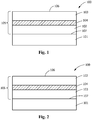
- Coated component 100 comprises a substrate 101 and a dual layer coating system 105 overlying substrate 101.
- Dual layer coating system 105 comprises a diffusion barrier coating 102 and a corrosion-resistant coating 103.
- diffusion barrier coating 102 is adjacent substrate 101.
- Corrosion-resistant coating 103 comprises a greater concentration of silicon and aluminum than diffusion barrier coating 102, and dual layer coating system 105 includes an aluminide interdiffusion zone 104.
- substrate 101 comprises an alloy including, but not limited to, cobalt-based alloy, iron-based alloy, nickel-based alloy or combinations thereof. In another embodiment, substrate 101 is cobalt-based alloy. In another embodiment, substrate 101 is essentially devoid of aluminum. In another embodiment, substrate 101 is devoid of aluminum. In another embodiment, substrate 101 is cobalt-based alloy devoid of aluminum.
- substrate 101 is formed from a CoCrMo alloy.
- substrate 101 is formed from an alloy having a composition, by weight, of: about 10% nickel, about 29% chromium, about 7% tungsten, about 1% iron, about 0.25% carbon, about 0.01% boron, and balance cobalt (e.g., FSX414); about 3.5 to about 4.1% tungsten, about 9 to about 10% cobalt, about 13.7 to about 14.3% chromium, about 2.8 to about 3.2% aluminum, about 2.4 to about 3.1% of tantalum, about 4.7 to about 5.1% titanium, about 1.4 to about 1.7% molybdenum, about 0.35% of iron, about 0.005 to about 0.02% of boron, about 0.08 to about 0.12% of carbon and a balance of nickel (e.g., GTD 111); between about 22.2 and about 22.8% Cr, between about 18.5 and about 19.5% Co, about 2.3% Ti, between about 1.8 and about 2.2% W, about 1.2%
- nickel e
- substrate 101 is formed from an alloy having a composition, by weight, of: about 7.5% cobalt, about 7.0% chromium, about 6.5% tantalum, about 6.2% aluminum, about 5.0% tungsten, about 3.0% rhenium, about 1.5% molybdenum, about 0.15% hafnium, and a balance of nickel (e.g., René N5); about 9.3% and about 9.7% W, between about 9.0% and about 9.5% Co, between about 8.0% and about 8.5% Cr, between about 5.4% and about 5.7% Al, up to about 0.25% Si, up to about 0.1% Mn, between about 0.06% and about 0.09% C, incidental impurities, and a balance of Ni (e.g., MarM247); about 9.3% and about 9.7% W, between about 9.0% and about 9.5% Co, between about 8.0% and about 8.5% Cr, between about 5.4% and about 5.7% Al, up to about 0.25% Si, up to about 0.1% Mn, between about 0.06% and about 0.09% C, incidental im
- Particularly suitable substrates includes CoCrMo alloys that have been formed by direct metal laser melting (DMLM), alloys having a composition, by weight, of: about 10% nickel, about 29% chromium, about 7% tungsten, about 1% iron, about 0.25% carbon, about 0.01% boron, and balance cobalt (e.g., FSX414) that have been deposited by DMLM or direct metal laser sintering (DMLS) including ⁇ - ⁇ 'cobalt alloys that contain Al.
- DMLM direct metal laser melting
- DMLS direct metal laser sintering
- the concentration of aluminum in the alloy is less than about 1.0 wt% or less than about 0.8 wt% or less than about 0.5 wt% or less than about 0.1 wt% or less than about 0.05 wt% or less than about 0.01 wt%.
- René N5 is substantially a single crystal.
- Mar-M-247LC, IN738 and IN738LC are both equiaxed and directionally solidified (DS).
- substrate 101 comprises the combination of aforementioned materials.
- corrosion-resistant coating 103 is an aluminum and/or silicon rich corrosion-resistant coating.
- the corrosion-resistant coating comprises a greater concentration of silicon and aluminum than the diffusion barrier coating.
- corrosion-resistant coating 103 comprises 15 to 50% of aluminum and 2 to 15% of silicon based on the total weight of the corrosion-resistant coating.
- Dual layer coating system 105 comprises a concentration gradient in silicon and aluminum increasing from a boundary 107 between substrate 101 and diffusion barrier coating 102 to an outer surface 106 of corrosion-resistant coating 103.
- coated component 100 is a hot gas path component.
- coated component 100 is a turbine component including, but not limited to, blades (buckets), vanes (nozzles), shrouds, combustors, transition ducts, compressor blades, or combinations thereof.
- coated component 100 is a gas turbine component.
- Coated component 100 comprises a substrate 101 and a dual layer coating system 105 overlying substrate 101.
- Dual layer coating system 105 comprises a diffusion barrier coating 102 and a corrosion-resistant coating 103.
- corrosion-resistant coating 103 is adjacent substrate 101.
- Corrosion-resistant coating 103 comprises a greater concentration of silicon and aluminum than diffusion barrier coating 102
- dual layer coating system 105 includes an aluminide interdiffusion zone 104.
- dual layer coating system 105 comprises a concentration gradient in silicon and aluminum decreasing from a boundary 107 between substrate 101 and corrosion-resistant coating 103 to an outer surface 106 of diffusion barrier coating 102.
- a method 300 of preparing a coated component comprises providing a substrate (step 301). The method further includes applying a diffusion barrier coating 102 to the substrate 101 (step 302)
- the diffusion barrier coating 102 applied to the substrate 101 or the corrosion-resistant coating 103 is a MCrAlY bond coating alloy, where M is nickel, cobalt, iron, alloys thereof, or combinations thereof.
- the diffusion barrier coating 102 is applied by one or more thermal spraying techniques.
- the thermal spraying technique is high-velocity oxygen fuel (HVOF) spraying, vacuum plasma spraying (VPS), high-velocity air-fuel (HVAF) spraying, wire arc spraying, flame/combustion spraying, or any combinations thereof.
- the thermal spraying technique preferably heats the overlay material to a temperature of at least 1900 °C (3450 °F), alternatively to at least 2000 °C (3650 °F).
- the HVOF spraying technique heats the overlay material to the range of about 2750 °C to about 3600 °C (5000-6500 °F), alternatively about 2750 °C to about 3300 °C (5000-6000 °F), alternatively about 2750 °C to about 3050 °C (5000-5500 °F), alternatively about 3050 °C to about 3300°C (5500-6000 °F), alternatively about 3300 °C to about 3600 °C (6000-6500 °F), or any suitable combination, sub-combination, range, or sub-range thereof.
- the HVAF spraying technique heats the overlay material to the range of about 1900 °C to about 2000 °C (3450-3550 °F), alternatively about 1900 °C to about 1950 °C (3450-3550 °F), alternatively about 1950 °C to about 2000 °C (3550-3650 °F), or any suitable combination, sub-combination, range, or sub-range thereof.
- the diffusion barrier coating 102 is an aluminide.
- the diffusion barrier coating may be a slurry, a gel, or any other suitable material capable of application to the substrate 101 or the corrosion-resistant coating 103, such as vapor phase deposition.
- the aluminide in the diffusion barrier coating is preferably NiAl or Ni 2 Al 3 .
- the diffusion barrier coating includes aluminum at a concentration, by weight, of about 8% to about 35%, alternatively about 12% to about 32%, alternatively about 15% to about 25%, alternatively about 15% to about 20%, alternatively about 20% to about 25%, alternatively about 20% to about 30%, alternatively about 25% to about 30%, alternatively about 15%, alternatively about 20%, alternatively about 25%, alternatively about 30%, or any suitable combination, sub-combination, range, or sub-range thereof.
- the diffusion barrier coating 102 may be soaked or dipped in the slurry, gel, or other suitable material. Alternatively, the diffusion barrier coating forming material may be poured, sprayed, or brushed onto the substrate 101, and/or applied by any other application process capable of applying the diffusion barrier coating forming material. In some embodiments, the diffusion barrier coating 102 diffuses into the substrate 101, for example, by a diffusion depth.
- the diffusion depth may be at least about 25 microns (1 mil), alternatively at least about 38 microns (1.5 mils), alternatively at least about 50 microns (2 mils), alternatively about 25 microns (1 mil), alternatively about 38 microns (1.5 mils), alternatively about 50 microns (2 mils), alternatively within a range of about 25 microns (1 mil) to about 50 microns (2 mils), alternatively within a range of about 25 microns (1 mil) to about 38 microns (1.5 mils), alternatively within a range of about 38 microns (1.5 mils) to about 50 microns (2 mils), or any suitable combination, sub-combination, range, or sub-range thereof.
- the applying of the diffusion barrier coating 102 is followed by or done while heating the diffusion barrier coating 102 and/or the component 100.
- the substrate 101 is positioned in an atmospheric furnace and the heating is performed, for example, in an inert atmosphere, such as with argon gas and/or with low oxygen content.
- the heating is performed under a reduced pressure or a vacuum.
- the method further includes applying a corrosion-resistant coating 103 to the diffusion barrier coating (step 303).
- the corrosion-resistant coating comprises a greater concentration of silicon and aluminum than the diffusion barrier coating.
- the corrosion-resistant coating 103 is formed from application of a slurry including a donor powder, a binder, and a carrier, the donor powder including a metallic aluminum alloy.
- the donor material includes aluminum and silicon.
- the donor material includes at least 35 wt% aluminum or at least about 40 wt% or from about 40 wt% to about 45 wt% aluminum or from about 42 wt% to about 44 wt% aluminum or up to about 50 wt% aluminum.
- Suitable donor materials include, but are not limited to, aluminum alloys, aluminum containing compounds and other aluminum donor materials.
- the donor material may include additive components. Suitable additive components for the donor material may include, but are not limited to, powder in elemental form selected from at least one of the group consisting of silicon, chromium, titanium, tantalum or boron.
- the binder is a heat curable binder and may include any suitable binder material, such as inorganic salts.
- the binder material includes at least 10 wt% inorganic salt or at least about 20 wt% or from about 10 wt% to about 50 wt% inorganic salt or from about 15 wt% to about 30 wt% inorganic salt or from about 20 wt% to about 25 wt% inorganic salt.
- suitable binder materials include, but are not limited to, chromate compounds, phosphate compounds, molybdate compounds, tungstate compounds, and combinations thereof. Examples of binder components include phosphoric acid, chromic acid, and combinations thereof.
- the carrier may include inorganic or organic carriers. Suitable carriers include, but are not limited to, water, toluene, acetone, and combinations thereof. In one embodiment, the carrier is free of gel material. In one embodiment, the slurry is free of inert fillers and inorganic carriers. The absence of inert fillers and inorganic carriers prevents such materials from sintering and becoming entrapped in the substrate 102.
- Suitable slurry compositions for use with the present disclosure include a composition comprising less than about 20 wt% phosphoric acid, less than about 1 wt% chromic acid, less than or equal to 50 wt% aluminum powder and less than about 6 wt% silicon powder, and a balance water as carrier.
- Another suitable slurry composition includes about 35% aluminum powder, about 6% silicon powder, about 12% phosphate-chromate binder (binder salts), with a balance water as carrier.
- the slurry is applied to the substrate 101 and heated to dry and cure the slurry on the diffusion barrier coating 101 and to leave a dried coating material.
- the slurry includes, by weight, about 35 to about 65% of the donor powder, about 1 to about 25% of the binder, and balance essentially carrier.
- the applied slurry composition may include a non-uniform thickness with a minimum thickness of about 0.05 mm and a maximum thickness of about 1 mm or more, and the aluminide coating system 100 has a thickness which varies by about 0.01 mm or less, and is therefore essentially independent of the thickness of the slurry coating.
- the slurry coating may include a maximum thickness of about 1 mm.
- the slurry is applied to the surface of the substrate by any suitable technique. Suitable application techniques include spraying, rolling, dipping or brushing.
- the drying step is preferably accomplished by heating the coating slurry to a drying temperature of from about 125° F to about 300° F (about 52 °C to about 149 °C) in air, for a time of from about 1 to about 4 hours.
- the coating is cured prior to diffusion treatment into a green-body by heating to a temperature from about 572° F to about 752° F (about 300 °C to about 400 °C) for a time of from about 1 to about 4 hours.
- the applying, drying steps and curing steps may be repeated two times, three times, four times or more to provide a thicker dried coating.
- the slurry coating that has been applied to the diffusion barrier coating 102 which may have been dried or not, is heated to form the dual coating system 105.
- the coating chamber is evacuated, and may be backfilled with an inert or reducing atmosphere (such as argon or hydrogen, respectively).
- the slurry may be heated on the substrate to a temperature within a range of about 800 °C to about 900 °C or 825 °C to about 875 °C or 840 °C to about 860 °C.
- the temperature within the coating chamber is raised to a temperature sufficient to volatilize the slurry components, and aluminum is deposited on and into the substrate 102.
- the component 100 may be maintained at the diffusion temperature, for example, for a suitable duration, depending on the final thickness desired for the diffusion barrier coating 102 and the interdiffusion zone 104.
- the heat treatment may include any suitable duration, including, but not limited to, a duration from about 1 to 8 hours, alternatively from about 2 hours to about 7 hours, alternatively from about 3 hours to about 6 hours, or alternatively from about 4 to about 5 hours or alternatively from about 1 to about 3 hours or alternatively from about 1.5 to about 2.5 hours.
- the heat treatment of the slurry may form a residue.
- the residue may be removed by any suitable technique, including, but not limited to, directing forced gas flow at the aluminide coating system 100, grit blasting the aluminide coating system 100, or a combination thereof.
- the substrate 101 comprises an alloy including, but not limited to, cobalt-based alloy, iron-based alloy, nickel-based alloy or combinations thereof. In another embodiment, substrate 101 is cobalt-based alloy. In another embodiment, substrate 101 is essentially devoid of aluminum. In another embodiment, substrate 101 is devoid of aluminum. In one embodiment, substrate 101 is of FSX414, GTD 111, GTD 222, GTD 241, HASTELLOY X, Nimonic 263, HAYNES® 188, MarM509, MarM918, IN625, René N5, IN738, IN738LC, MarM247, MarM247LC or combinations thereof.
- the diffusion barrier coating 102 includes MCrAlY, gel aluminide or combinations thereof. In another embodiment, the diffusion barrier coating 102 is essentially devoid of silicon. In another embodiment, the diffusion barrier coating 102 is devoid of silicon. In one embodiment, diffusion barrier coating 102 is more ductile and oxidation-protective than corrosion-resistant coating 103.
- the step of applying a diffusion barrier coating to the substrate comprises slurry, gel aluminide, any suitable diffusion aluminide, diffusion, EBPVD, plasma jet, air jet, air plasma jet, or combinations thereof.
- the dual layer coating system 105 comprises a concentration gradient in silicon and aluminum increasing from a boundary 107 between the substrate 101 and the diffusion barrier coating 102 to an outer surface 106 of the corrosion-resistant coating 103.
- method 300 further comprises a step of heating-treating the component to form an interdiffusion zone between the diffusion barrier coating and the corrosion-resistant coating.
- the heat treatment optimization creates more dispersed and continuous aluminide interdiffusion zone (IDZ).
- the method 300 further comprises a step of post-heat treating the component.
- the post-heat treating may include, for example, heating with a furnace to bring up the temperature of the gas turbine component.
- the post-heat treatment preferably alters the material of the dual coating system 105 and/or substrate 101 to allow the material from the diffusion zone to flow between the coating layers and between the coating layers and substrate 101 and to further bond the dual layer system 105 to the substrate 101.
- a suitable post-heat treatment includes suitable temperatures, for example, temperatures of about 870 °C to about 1200 °C (1600 °F to 2200 °F), alternatively about 1040 °C to about 1180 °C (1900 °F to 2150 °F), alternatively about 1070 °C to about 1150 °C (1950 °F to 2100 °F), alternatively at about 1080 °C (1975 °F), alternatively at about 1090 °C (2000 °F), alternatively at about 1120 °C (2050 °F), or any suitable combination, sub-combination, range, or sub-range thereof.
- heat treating is at a temperature capable of forming a ductile intermetallic material, such as a ductile aluminide, for example, having a strain range of about 4% and/or permitting the component 100 to be devoid or substantially devoid of cracking formed by application of a brittle aluminide.
- a ductile intermetallic material such as a ductile aluminide, for example, having a strain range of about 4% and/or permitting the component 100 to be devoid or substantially devoid of cracking formed by application of a brittle aluminide.
- the coated component is a hot gas path component.
- the coated component is a turbine component including, but not limited to, blades (buckets), vanes (nozzles), shrouds, combustors, transition ducts, or combinations thereof.
- the coated component is a gas turbine component.
- a method 400 of preparing a coated component comprises providing a substrate (step 401).
- the method further includes applying a corrosion-resistant coating 103 to the substrate 101 (step 402).
- the method further includes applying a diffusion barrier coating 102 to the corrosion-resistant coating 103 (step 403).
- Each step can be implemented by the aforementioned corresponding methods described above with respect to FIG. 3 .
- the dual layer coating system 105 comprises a concentration gradient in silicon and aluminum increasing from a boundary 107 between the substrate 101 and the corrosion-resistant coating 103 to an outer surface 106 of the diffusion barrier coating 102.
Abstract
Description
- The present disclosure is generally directed to a coated component and a method of preparing a coated component. More specifically, the present disclosure is generally directed to a coated alloy component and a method of preparing a coated alloy component.
- Gas turbines for power generation systems must satisfy the highest demands with respect to reliability, power, efficiency, economy, and operating service life. Modern high-efficiency combustion turbines have firing temperatures that exceed about 2,300 °F (1,260 °C), and firing temperatures continue to increase as demand for more efficient engines continues. Many components that form the combustor and "hot gas path" turbine sections are directly exposed to aggressive hot combustion gases. The use of coatings on turbine components, such as combustors, combustion liners, combustion transition pieces, combustion hardware, blades (buckets), vanes (nozzles) and shrouds, is important in commercial gas turbine engines.
- Traditional oxidation coatings made of MCrAlY as well as diffusion aluminides are susceptible to hot corrosion in combustion environments. In certain coating systems, in order to enable a better hot corrosion resistant coating, the coating chemistry is adjusted to include Si as an alloying element. However, the addition of Si results in a coating that is brittle. Furthermore, known coating systems that are hot corrosion resistant are not always oxidation resistant.
- In an exemplary embodiment, a coated component is provided. The coated component comprises a substrate and a dual layer coating system overlying the substrate. The dual layer coating system comprises a diffusion barrier coating and a corrosion-resistant coating. The corrosion-resistant coating comprises a greater concentration of silicon and aluminum than the diffusion barrier coating, and the dual layer coating system includes an aluminide interdiffusion zone.
- In another exemplary embodiment, a method of preparing a coated component is provided. The method includes providing a substrate; and applying a dual coating system to the substrate. The applying of the dual coating system includes applying a diffusion barrier coating; and applying a corrosion-resistant coating. The corrosion-resistant coating comprises a greater concentration of silicon and aluminum than the diffusion barrier coating.
- Other features and advantages of the present invention will be apparent from the following more detailed description of the preferred embodiment, taken in conjunction with the accompanying drawings, which illustrate, by way of example, the principles of the invention.
-
-
FIG. 1 illustrates a coated component, according to an embodiment of the present disclosure. -
FIG. 2 illustrates a coated component, according to an embodiment of the present disclosure. -
FIG. 3 is a flow chart illustrating a method of welding a treated component, according to an embodiment of the present disclosure. -
FIG. 4 is a flow chart illustrating a method of welding a treated component, according to an embodiment of the present disclosure. - The detailed description set forth below in connection with the appended drawings where like numerals reference like elements is intended as a description of various embodiments of the disclosed subject matter and is not intended to represent the only embodiments. Each embodiment described in this disclosure is provided merely as an example or illustration and should not be construed as preferred or advantageous over other embodiments. The illustrative examples provided herein are not intended to be exhaustive or to limit the claimed subject matter to the precise forms disclosed.
- Provided are an exemplary coated component and a method of preparing a coated component. Embodiments of the present disclosure, in comparison to components and method not utilizing one or more features disclosed herein, enable the formation of a durable, gradient dual layer coating system resistant to hot corrosion as well as oxidation, thereby extending the service life of the coated component without affecting functionality. Without the dual layer coating system, the components are limited in their operating temperatures and have increased service and/or repair requirements.
- All numbers expressing quantities of ingredients and/or reaction conditions are to be understood as being modified in all instances by the term "about", unless otherwise indicated.
- All percentages and ratios are calculated by weight unless otherwise indicated. All percentages are calculated based on the total weight of a composition unless otherwise indicated. All component or composition levels are in reference to the active level of that component or composition, and are exclusive of impurities, for example, residual solvents or by-products, which may be present in commercially available sources.
- The articles "a" and "an," as used herein, mean one or more when applied to any feature in embodiments of the present invention described in the specification and claims. The use of "a" and "an" does not limit the meaning to a single feature unless such a limit is specifically stated. The article "the" preceding singular or plural nouns or noun phrases denotes a particular specified feature or particular specified features and may have a singular or plural connotation depending upon the context in which it is used. The adjective "any" means one, some, or all indiscriminately of whatever quantity.
- The term "at least one," as used herein, means one or more and thus includes individual components as well as mixtures/combinations.
- The term "comprising" (and its grammatical variations), as used herein, is used in the inclusive sense of "having" or "including" and not in the exclusive sense of "consisting only of."
- The term "essentially devoid of " means containing less than 2 percent by weight of, preferably less than 1 percent by weight of, more preferably less than 0.1 percent any weight of, more preferably less than 0.01 percent by weight of, and even more preferably free of.
- With reference to
FIG. 1 , a coatedcomponent 100 is provided. Coatedcomponent 100 comprises asubstrate 101 and a duallayer coating system 105 overlyingsubstrate 101. Duallayer coating system 105 comprises adiffusion barrier coating 102 and a corrosion-resistant coating 103. In the embodiment shown inFIG. 1 ,diffusion barrier coating 102 isadjacent substrate 101. Corrosion-resistant coating 103 comprises a greater concentration of silicon and aluminum thandiffusion barrier coating 102, and duallayer coating system 105 includes analuminide interdiffusion zone 104. - In one embodiment,
substrate 101 comprises an alloy including, but not limited to, cobalt-based alloy, iron-based alloy, nickel-based alloy or combinations thereof. In another embodiment,substrate 101 is cobalt-based alloy. In another embodiment,substrate 101 is essentially devoid of aluminum. In another embodiment,substrate 101 is devoid of aluminum. In another embodiment,substrate 101 is cobalt-based alloy devoid of aluminum. - In one embodiment,
substrate 101 is formed from a CoCrMo alloy. In another embodiment,substrate 101 is formed from an alloy having a composition, by weight, of: about 10% nickel, about 29% chromium, about 7% tungsten, about 1% iron, about 0.25% carbon, about 0.01% boron, and balance cobalt (e.g., FSX414); about 3.5 to about 4.1% tungsten, about 9 to about 10% cobalt, about 13.7 to about 14.3% chromium, about 2.8 to about 3.2% aluminum, about 2.4 to about 3.1% of tantalum, about 4.7 to about 5.1% titanium, about 1.4 to about 1.7% molybdenum, about 0.35% of iron, about 0.005 to about 0.02% of boron, about 0.08 to about 0.12% of carbon and a balance of nickel (e.g., GTD 111); between about 22.2 and about 22.8% Cr, between about 18.5 and about 19.5% Co, about 2.3% Ti, between about 1.8 and about 2.2% W, about 1.2% Al, about 1.0% Ta, about 0.8% Nb, about 0.25% Si, between about 0.08 and about 0.12% C, about 0.10% Mn, about 0.05% Zr, about 0.008% B, incidental impurities, and a balance of Ni (e.g., GTD 222); about 22.5% Cr, about 19% Co, about 2% W, about 1.35% Nb, about 2.3% Ti, about 1.2% Al, about 0.1% C, incidental impurities, and a balance of Ni (e.g., GTD 241); between about 8% and about 10% molybdenum (Mo), between about 20.5% and about 23% chromium (Cr), between about 17% and about 20% iron (Fe), between about 0.2% and about 1% tungsten (W), between about 0.5% and about 2.5% cobalt (Co), between about 0.05% and about 0.15% carbon (C), up to about 1% silicon (Si), up to about 1% manganese (Mn), up to about 0.01% boron (B), up to about 0.04% phosphorus (P), up to about 0.03 sulfur (S), incidental impurities, and a balance of nickel (Ni) (e.g., HASTELLOY X); between about 19% and about 21% chromium (Cr), between about 19% and about 21% cobalt (Co), between about 5.6% and about 6.1% molybdenum (Mo), between about 1.9% and about 2.4% titanium (Ti), up to about 0.6% aluminum (Al), up to about 0.6% manganese (Mn), up to about 0.4% silicon (Si), up to about 0.2% copper (Cu), incidental impurities, and a balance of nickel (Ni) (e.g., Nimonic 263); about 0.015% boron, about 0.05% to about 0.15% carbon, about 20% to about 24% chromium, about 3% iron, about 0.02% to about 0.12% lanthanum, about 1.25% manganese, about 20% to about 24% nickel, about 0.2% to about 0.5% silicon, about 13% to about 15% tungsten, and balance cobalt (e.g., HAYNES® 188); about 22.5% to about 24.25% chromium, up to about 0.3% titanium (e.g., about 0.15% to about 0.3% titanium), about 6.5% to about 7.5% tungsten, about 9% to about 11% nickel, about 3% to about 4% tantalum, up to about 0.65% carbon (e.g., about 0.55% to about 0.65% carbon), about 2% to about 3% boron (e.g., about 2% to about 3% boron), about 1.3% iron, up to about 0.4% silicon, up to about 0.1% manganese, up to about 0.02% sulfur, and balance cobalt (e.g., MarM509); about 0.05% carbon, about 20% nickel, about 20% chromium, about 0.1% zirconium, about 7.5% tantalum, and balance cobalt (e.g., MarM918); about 5% iron, about 20% to about 23% chromium, up to about 0.5% silicon, about 8% to about 10% molybdenum, up to about 0.5% manganese, up to about 0.1% carbon, and balance nickel (e.g., IN625). In another embodiment,substrate 101 is formed from an alloy having a composition, by weight, of: about 7.5% cobalt, about 7.0% chromium, about 6.5% tantalum, about 6.2% aluminum, about 5.0% tungsten, about 3.0% rhenium, about 1.5% molybdenum, about 0.15% hafnium, and a balance of nickel (e.g., René N5); about 9.3% and about 9.7% W, between about 9.0% and about 9.5% Co, between about 8.0% and about 8.5% Cr, between about 5.4% and about 5.7% Al, up to about 0.25% Si, up to about 0.1% Mn, between about 0.06% and about 0.09% C, incidental impurities, and a balance of Ni (e.g., MarM247); about 9.3% and about 9.7% W, between about 9.0% and about 9.5% Co, between about 8.0% and about 8.5% Cr, between about 5.4% and about 5.7% Al, up to about 0.25% Si, up to about 0.1% Mn, between about 0.06% and about 0.09% C, incidental impurities, and a balance of Ni (e.g., MarM247LC); about 15.7% and about 16.3% Cr, about 8.0% to about 9.0% Co, between about 3.2% and about 3.7% Ti, between about 3.2% and about 3.7% Al, between about 2.4% and about 2.8% W, between about 1.5% and about 2.0% Ta, between about 1.5% and about 2.0% Mo, between about 0.6% and about 1.1% Nb, up to about 0.5% Fe, up to about 0.3% Si, up to about 0.2% Mn, between about 0.15% and about 0.20% C, between about 0.05% and about 0.15% Zr, up to about 0.015% S, between about 0.005% and about 0.015% B, incidental impurities, and a balance of Ni (e.g., IN738); about 15.7% and about 16.3% Cr, about 8.0% to about 9.0% Co, between about 3.2% and about 3.7% Ti, between about 3.2% and about 3.7% Al, between about 2.4% and about 2.8% W, between about 1.5% and about 2.0% Ta, between about 1.5% and about 2.0% Mo, between about 0.6% and about 1.1% Nb, up to about 0.5% Fe, up to about 0.3% Si, up to about 0.2% Mn, between about 0.10% and about 0.20% C, between about 0.5% and about 1.0% Zr, up to about 0.015% S, between about 0.005% and about 0.015% B, incidental impurities, and a balance of Ni (e.g., IN738LC). Particularly suitable substrates includes CoCrMo alloys that have been formed by direct metal laser melting (DMLM), alloys having a composition, by weight, of: about 10% nickel, about 29% chromium, about 7% tungsten, about 1% iron, about 0.25% carbon, about 0.01% boron, and balance cobalt (e.g., FSX414) that have been deposited by DMLM or direct metal laser sintering (DMLS) including γ-γ'cobalt alloys that contain Al. In one embodiment, the concentration of aluminum in the alloy is less than about 1.0 wt% or less than about 0.8 wt% or less than about 0.5 wt% or less than about 0.1 wt% or less than about 0.05 wt% or less than about 0.01 wt%. In one embodiment, René N5 is substantially a single crystal. In one embodiment, Mar-M-247LC, IN738 and IN738LC are both equiaxed and directionally solidified (DS). In one embodiment,substrate 101 comprises the combination of aforementioned materials. - In one embodiment,
diffusion barrier coating 102 includes MCrAlY (M=Ni, Co, Fe or combinations thereof), gel aluminide or combinations thereof. In another embodiment, the diffusion barrier coating is devoid of silicon. In one embodiment,diffusion barrier coating 102 is more ductile and oxidation-protective than corrosion-resistant coating 103. - In one embodiment, corrosion-
resistant coating 103 is an aluminum and/or silicon rich corrosion-resistant coating. The corrosion-resistant coating comprises a greater concentration of silicon and aluminum than the diffusion barrier coating. - In one embodiment, corrosion-
resistant coating 103 comprises 15 to 50% of aluminum and 2 to 15% of silicon based on the total weight of the corrosion-resistant coating. - Dual
layer coating system 105 comprises a concentration gradient in silicon and aluminum increasing from aboundary 107 betweensubstrate 101 anddiffusion barrier coating 102 to anouter surface 106 of corrosion-resistant coating 103. - In one embodiment,
coated component 100 is a hot gas path component. In another embodiment,coated component 100 is a turbine component including, but not limited to, blades (buckets), vanes (nozzles), shrouds, combustors, transition ducts, compressor blades, or combinations thereof. In another embodiment,coated component 100 is a gas turbine component. - With reference to
FIG. 2 , acoated component 100 is provided.Coated component 100 comprises asubstrate 101 and a duallayer coating system 105overlying substrate 101. Duallayer coating system 105 comprises adiffusion barrier coating 102 and a corrosion-resistant coating 103. In the embodiment shown inFIG. 2 , corrosion-resistant coating 103 isadjacent substrate 101. Corrosion-resistant coating 103 comprises a greater concentration of silicon and aluminum thandiffusion barrier coating 102, and duallayer coating system 105 includes an aluminide interdiffusionzone 104. In one embodiment, duallayer coating system 105 comprises a concentration gradient in silicon and aluminum decreasing from aboundary 107 betweensubstrate 101 and corrosion-resistant coating 103 to anouter surface 106 ofdiffusion barrier coating 102. - With reference to
FIG. 3 , amethod 300 of preparing a coated component is provided. Themethod 300 comprises providing a substrate (step 301). The method further includes applying adiffusion barrier coating 102 to the substrate 101 (step 302) - In some embodiments, the
diffusion barrier coating 102 applied to thesubstrate 101 or the corrosion-resistant coating 103 is a MCrAlY bond coating alloy, where M is nickel, cobalt, iron, alloys thereof, or combinations thereof. - In some embodiments, the
diffusion barrier coating 102 is applied by one or more thermal spraying techniques. In some embodiments, the thermal spraying technique is high-velocity oxygen fuel (HVOF) spraying, vacuum plasma spraying (VPS), high-velocity air-fuel (HVAF) spraying, wire arc spraying, flame/combustion spraying, or any combinations thereof. The thermal spraying technique preferably heats the overlay material to a temperature of at least 1900 °C (3450 °F), alternatively to at least 2000 °C (3650 °F). In some embodiments, the HVOF spraying technique heats the overlay material to the range of about 2750 °C to about 3600 °C (5000-6500 °F), alternatively about 2750 °C to about 3300 °C (5000-6000 °F), alternatively about 2750 °C to about 3050 °C (5000-5500 °F), alternatively about 3050 °C to about 3300°C (5500-6000 °F), alternatively about 3300 °C to about 3600 °C (6000-6500 °F), or any suitable combination, sub-combination, range, or sub-range thereof. In some embodiments, the HVAF spraying technique heats the overlay material to the range of about 1900 °C to about 2000 °C (3450-3550 °F), alternatively about 1900 °C to about 1950 °C (3450-3550 °F), alternatively about 1950 °C to about 2000 °C (3550-3650 °F), or any suitable combination, sub-combination, range, or sub-range thereof. - In some embodiments, the
diffusion barrier coating 102 is an aluminide. In such embodiments, the diffusion barrier coating may be a slurry, a gel, or any other suitable material capable of application to thesubstrate 101 or the corrosion-resistant coating 103, such as vapor phase deposition. The aluminide in the diffusion barrier coating is preferably NiAl or Ni2Al3. In some embodiments, the diffusion barrier coating includes aluminum at a concentration, by weight, of about 8% to about 35%, alternatively about 12% to about 32%, alternatively about 15% to about 25%, alternatively about 15% to about 20%, alternatively about 20% to about 25%, alternatively about 20% to about 30%, alternatively about 25% to about 30%, alternatively about 15%, alternatively about 20%, alternatively about 25%, alternatively about 30%, or any suitable combination, sub-combination, range, or sub-range thereof. - The
diffusion barrier coating 102 may be soaked or dipped in the slurry, gel, or other suitable material. Alternatively, the diffusion barrier coating forming material may be poured, sprayed, or brushed onto thesubstrate 101, and/or applied by any other application process capable of applying the diffusion barrier coating forming material. In some embodiments, thediffusion barrier coating 102 diffuses into thesubstrate 101, for example, by a diffusion depth. The diffusion depth may be at least about 25 microns (1 mil), alternatively at least about 38 microns (1.5 mils), alternatively at least about 50 microns (2 mils), alternatively about 25 microns (1 mil), alternatively about 38 microns (1.5 mils), alternatively about 50 microns (2 mils), alternatively within a range of about 25 microns (1 mil) to about 50 microns (2 mils), alternatively within a range of about 25 microns (1 mil) to about 38 microns (1.5 mils), alternatively within a range of about 38 microns (1.5 mils) to about 50 microns (2 mils), or any suitable combination, sub-combination, range, or sub-range thereof. - In some embodiments, the applying of the
diffusion barrier coating 102 is followed by or done while heating thediffusion barrier coating 102 and/or thecomponent 100. For example, in one embodiment, thesubstrate 101 is positioned in an atmospheric furnace and the heating is performed, for example, in an inert atmosphere, such as with argon gas and/or with low oxygen content. In some embodiments, the heating is performed under a reduced pressure or a vacuum. - With reference to
FIG. 3 , the method further includes applying a corrosion-resistant coating 103 to the diffusion barrier coating (step 303). The corrosion-resistant coating comprises a greater concentration of silicon and aluminum than the diffusion barrier coating. - In some embodiments, the corrosion-
resistant coating 103 is formed from application of a slurry including a donor powder, a binder, and a carrier, the donor powder including a metallic aluminum alloy. In one embodiment, the donor material includes aluminum and silicon. In one embodiment, the donor material includes at least 35 wt% aluminum or at least about 40 wt% or from about 40 wt% to about 45 wt% aluminum or from about 42 wt% to about 44 wt% aluminum or up to about 50 wt% aluminum. Suitable donor materials include, but are not limited to, aluminum alloys, aluminum containing compounds and other aluminum donor materials. The donor material may include additive components. Suitable additive components for the donor material may include, but are not limited to, powder in elemental form selected from at least one of the group consisting of silicon, chromium, titanium, tantalum or boron. - The binder is a heat curable binder and may include any suitable binder material, such as inorganic salts. In one embodiment, the binder material includes at least 10 wt% inorganic salt or at least about 20 wt% or from about 10 wt% to about 50 wt% inorganic salt or from about 15 wt% to about 30 wt% inorganic salt or from about 20 wt% to about 25 wt% inorganic salt. Suitable binder materials include, but are not limited to, chromate compounds, phosphate compounds, molybdate compounds, tungstate compounds, and combinations thereof. Examples of binder components include phosphoric acid, chromic acid, and combinations thereof.
- The carrier may include inorganic or organic carriers. Suitable carriers include, but are not limited to, water, toluene, acetone, and combinations thereof. In one embodiment, the carrier is free of gel material. In one embodiment, the slurry is free of inert fillers and inorganic carriers. The absence of inert fillers and inorganic carriers prevents such materials from sintering and becoming entrapped in the
substrate 102. - Suitable slurry compositions for use with the present disclosure include a composition comprising less than about 20 wt% phosphoric acid, less than about 1 wt% chromic acid, less than or equal to 50 wt% aluminum powder and less than about 6 wt% silicon powder, and a balance water as carrier. Another suitable slurry composition includes about 35% aluminum powder, about 6% silicon powder, about 12% phosphate-chromate binder (binder salts), with a balance water as carrier.
- The slurry is applied to the
substrate 101 and heated to dry and cure the slurry on thediffusion barrier coating 101 and to leave a dried coating material. In one embodiment, the slurry includes, by weight, about 35 to about 65% of the donor powder, about 1 to about 25% of the binder, and balance essentially carrier. The applied slurry composition may include a non-uniform thickness with a minimum thickness of about 0.05 mm and a maximum thickness of about 1 mm or more, and thealuminide coating system 100 has a thickness which varies by about 0.01 mm or less, and is therefore essentially independent of the thickness of the slurry coating. The slurry coating may include a maximum thickness of about 1 mm. The slurry is applied to the surface of the substrate by any suitable technique. Suitable application techniques include spraying, rolling, dipping or brushing. - The drying step is preferably accomplished by heating the coating slurry to a drying temperature of from about 125° F to about 300° F (about 52 °C to about 149 °C) in air, for a time of from about 1 to about 4 hours. In addition, the coating is cured prior to diffusion treatment into a green-body by heating to a temperature from about 572° F to about 752° F (about 300 °C to about 400 °C) for a time of from about 1 to about 4 hours. In one embodiment, the applying, drying steps and curing steps may be repeated two times, three times, four times or more to provide a thicker dried coating.
- The slurry coating that has been applied to the
diffusion barrier coating 102, which may have been dried or not, is heated to form thedual coating system 105. The coating chamber is evacuated, and may be backfilled with an inert or reducing atmosphere (such as argon or hydrogen, respectively). The slurry may be heated on the substrate to a temperature within a range of about 800 °C to about 900 °C or 825 °C to about 875 °C or 840 °C to about 860 °C. The temperature within the coating chamber is raised to a temperature sufficient to volatilize the slurry components, and aluminum is deposited on and into thesubstrate 102. Thecomponent 100 may be maintained at the diffusion temperature, for example, for a suitable duration, depending on the final thickness desired for thediffusion barrier coating 102 and theinterdiffusion zone 104. The heat treatment may include any suitable duration, including, but not limited to, a duration from about 1 to 8 hours, alternatively from about 2 hours to about 7 hours, alternatively from about 3 hours to about 6 hours, or alternatively from about 4 to about 5 hours or alternatively from about 1 to about 3 hours or alternatively from about 1.5 to about 2.5 hours. The heat treatment of the slurry may form a residue. The residue may be removed by any suitable technique, including, but not limited to, directing forced gas flow at thealuminide coating system 100, grit blasting thealuminide coating system 100, or a combination thereof. - In one embodiment, the
substrate 101 comprises an alloy including, but not limited to, cobalt-based alloy, iron-based alloy, nickel-based alloy or combinations thereof. In another embodiment,substrate 101 is cobalt-based alloy. In another embodiment,substrate 101 is essentially devoid of aluminum. In another embodiment,substrate 101 is devoid of aluminum. In one embodiment,substrate 101 is of FSX414, GTD 111, GTD 222, GTD 241, HASTELLOY X, Nimonic 263, HAYNES® 188, MarM509, MarM918, IN625, René N5, IN738, IN738LC, MarM247, MarM247LC or combinations thereof. - In one embodiment, the
diffusion barrier coating 102 includes MCrAlY, gel aluminide or combinations thereof. In another embodiment, thediffusion barrier coating 102 is essentially devoid of silicon. In another embodiment, thediffusion barrier coating 102 is devoid of silicon. In one embodiment,diffusion barrier coating 102 is more ductile and oxidation-protective than corrosion-resistant coating 103. - In one embodiment, the step of applying a diffusion barrier coating to the substrate (step 302) comprises slurry, gel aluminide, any suitable diffusion aluminide, diffusion, EBPVD, plasma jet, air jet, air plasma jet, or combinations thereof.
- With reference to
FIG. 3 , the duallayer coating system 105 comprises a concentration gradient in silicon and aluminum increasing from aboundary 107 between thesubstrate 101 and thediffusion barrier coating 102 to anouter surface 106 of the corrosion-resistant coating 103. - In one embodiment,
method 300 further comprises a step of heating-treating the component to form an interdiffusion zone between the diffusion barrier coating and the corrosion-resistant coating. The heat treatment optimization creates more dispersed and continuous aluminide interdiffusion zone (IDZ). - In one embodiment, the
method 300 further comprises a step of post-heat treating the component. The post-heat treating may include, for example, heating with a furnace to bring up the temperature of the gas turbine component. The post-heat treatment preferably alters the material of thedual coating system 105 and/orsubstrate 101 to allow the material from the diffusion zone to flow between the coating layers and between the coating layers andsubstrate 101 and to further bond thedual layer system 105 to thesubstrate 101. - A suitable post-heat treatment includes suitable temperatures, for example, temperatures of about 870 °C to about 1200 °C (1600 °F to 2200 °F), alternatively about 1040 °C to about 1180 °C (1900 °F to 2150 °F), alternatively about 1070 °C to about 1150 °C (1950 °F to 2100 °F), alternatively at about 1080 °C (1975 °F), alternatively at about 1090 °C (2000 °F), alternatively at about 1120 °C (2050 °F), or any suitable combination, sub-combination, range, or sub-range thereof. In one embodiment, heat treating is at a temperature capable of forming a ductile intermetallic material, such as a ductile aluminide, for example, having a strain range of about 4% and/or permitting the
component 100 to be devoid or substantially devoid of cracking formed by application of a brittle aluminide. - In one embodiment, the coated component is a hot gas path component. In another embodiment, the coated component is a turbine component including, but not limited to, blades (buckets), vanes (nozzles), shrouds, combustors, transition ducts, or combinations thereof. In another embodiment, the coated component is a gas turbine component.
- With reference to
FIG. 4 , amethod 400 of preparing a coated component is provided. Themethod 400 comprises providing a substrate (step 401). The method further includes applying a corrosion-resistant coating 103 to the substrate 101 (step 402). The method further includes applying adiffusion barrier coating 102 to the corrosion-resistant coating 103 (step 403). Each step can be implemented by the aforementioned corresponding methods described above with respect toFIG. 3 . - In one embodiment, the dual
layer coating system 105 comprises a concentration gradient in silicon and aluminum increasing from aboundary 107 between thesubstrate 101 and the corrosion-resistant coating 103 to anouter surface 106 of thediffusion barrier coating 102. - While the invention has been described with reference to a preferred embodiment, it will be understood by those skilled in the art that various changes may be made and equivalents may be substituted for elements thereof without departing from the scope of the invention. In addition, many modifications may be made to adapt a particular situation or material to the teachings of the invention without departing from the essential scope thereof. Therefore, it is intended that the invention not be limited to the particular embodiment disclosed as the best mode contemplated for carrying out this invention, but that the invention will include all embodiments falling within the scope of the appended claims. Various aspects and embodiments of the present invention will now be defined by the following numbered clauses:
- 1. A coated component comprising:
- a substrate; and
- a dual layer coating system overlying the substrate, comprising:
- a diffusion barrier coating;
- a corrosion-resistant coating,
- wherein the corrosion-resistant coating comprises a greater concentration of silicon and aluminum than the diffusion barrier coating, and
- wherein the dual layer coating system includes an aluminide interdiffusion zone.
- 2. The coated component of clause 1, wherein the substrate comprises an alloy selected from the group consisting of cobalt-based alloy, iron-based alloy, nickel-based alloy and combinations thereof.
- 3. The coated component of clause 1, wherein the substrate is devoid of aluminum.
- 4. The coated component of clause 1, wherein the corrosion-resistant coating includes a sufficient amount of silicon and aluminum to form the aluminide interdiffusion zone.
- 5. The coated component of clause 1, wherein the diffusion barrier coating is selected from the group consisting of MCrAlY, gel aluminide and combinations thereof.
- 6. The coated component of clause 1, wherein the diffusion barrier coating is devoid of silicon.
- 7. The coated component of clause 1, wherein the diffusion barrier coating or the corrosion-resistant coating is adjacent the substrate.
- 8. The coated component of clause 1, wherein the dual layer coating system comprises a concentration gradient in silicon and aluminum decreasing from a boundary between the substrate and the corrosion-resistant coating to an outer surface of the diffusion barrier coating.
- 9. The coated component of clause 1, wherein the dual layer coating system comprises a concentration gradient in silicon and aluminum increasing from a boundary between the substrate and the diffusion barrier coating to an outer surface of the corrosion-resistant coating.
- 10. A method of preparing a coated component comprising:
- providing a substrate;
- applying a dual coating system to the substrate, the applying of the dual coating system comprising:
- applying a diffusion barrier coating; and
- applying a corrosion-resistant coating,
- wherein the corrosion-resistant coating comprises a greater concentration of silicon and aluminum than the diffusion barrier coating.
- 11. The method of clause 10, wherein the corrosion-resistant coating is applied to the substrate and the diffusion barrier coating is applied to the corrosion-resistant coating.
- 12. The method of clause 11, wherein the dual layer coating system comprises a concentration gradient in silicon and aluminum decreasing from a boundary between the substrate and the corrosion-resistant coating to an outer surface of the diffusion barrier coating.
- 13. The method of clause 11, wherein the applying the corrosion resistant coating comprises heat-treating the corrosion-resistant coating.
- 14. The method of clause 11, wherein the applying the diffusion barrier coating comprises heat-treating the component to form an interdiffusion zone between the diffusion barrier coating and the corrosion-resistant coating.
- 15. The method of clause 10, wherein the diffusion barrier coating is applied to the substrate and the corrosion-resistant coating to the diffusion barrier coating.
- 16. The method of clause 15, wherein the dual layer coating system comprises a concentration gradient in silicon and aluminum increasing from a boundary between the substrate and the diffusion barrier coating to an outer surface of the corrosion-resistant coating.
- 17. The method of clause 15, wherein the applying the diffusion barrier coating comprises heat-treating the component to form the diffusion barrier coating.
- 18. The method of clause 15, wherein the applying the corrosion resistant coating comprises heat-treating the corrosion resistant coating to form an interdiffusion zone between the corrosion-resistant coating and the diffusion barrier coating.
- 19. The method of clause 10, further comprising post-heat treating the component.
- 20. The method of clause 10, wherein the substrate comprises an alloy selected from the group consisting of cobalt-based alloy, iron-based alloy, nickel-based alloy and combinations thereof.
Claims (15)
- A coated component comprising:a substrate; anda dual layer coating system overlying the substrate, comprising:a diffusion barrier coating;a corrosion-resistant coating,wherein the corrosion-resistant coating comprises a greater concentration of silicon andaluminum than the diffusion barrier coating, andwherein the dual layer coating system includes an aluminide interdiffusion zone.
- The coated component of claim 1, wherein the substrate comprises an alloy selected from the group consisting of cobalt-based alloy, iron-based alloy, nickel-based alloy and combinations thereof.
- The coated component of claim 1, wherein the substrate is devoid of aluminum.
- The coated component of claim 1, wherein the corrosion-resistant coating includes a sufficient amount of silicon and aluminum to form the aluminide interdiffusion zone.
- The coated component of claim 1, wherein the diffusion barrier coating is selected from the group consisting of MCrAlY, gel aluminide and combinations thereof.
- The coated component of claim 1, wherein the diffusion barrier coating is devoid of silicon.
- The coated component of claim 1, wherein the diffusion barrier coating or the corrosion-resistant coating is adjacent the substrate.
- The coated component of claim 1, wherein the dual layer coating system comprises a concentration gradient in silicon and aluminum decreasing from a boundary between the substrate and the corrosion-resistant coating to an outer surface of the diffusion barrier coating.
- The coated component of claim 1, wherein the dual layer coating system comprises a concentration gradient in silicon and aluminum increasing from a boundary between the substrate and the diffusion barrier coating to an outer surface of the corrosion-resistant coating.
- A method of preparing a coated component comprising:providing a substrate;applying a dual coating system to the substrate, the applying of the dual coating system comprising:applying a diffusion barrier coating; andapplying a corrosion-resistant coating,wherein the corrosion-resistant coating comprises a greater concentration of silicon andaluminum than the diffusion barrier coating.
- The method of claim 10, wherein the corrosion-resistant coating is applied to the substrate and the diffusion barrier coating is applied to the corrosion-resistant coating.
- The method of claim 11, wherein the dual layer coating system comprises a concentration gradient in silicon and aluminum decreasing from a boundary between the substrate and the corrosion-resistant coating to an outer surface of the diffusion barrier coating.
- The method of claim 11, wherein the applying the corrosion resistant coating comprises heat-treating the corrosion-resistant coating.
- The method of claim 11, wherein the applying the diffusion barrier coating comprises heat-treating the component to form an interdiffusion zone between the diffusion barrier coating and the corrosion-resistant coating.
- The method of claim 10, wherein the diffusion barrier coating is applied to the substrate and the corrosion-resistant coating to the diffusion barrier coating.
Applications Claiming Priority (1)
| Application Number | Priority Date | Filing Date | Title |
|---|---|---|---|
| IN201741036271 | 2017-10-12 |
Publications (1)
| Publication Number | Publication Date |
|---|---|
| EP3470543A1 true EP3470543A1 (en) | 2019-04-17 |
Family
ID=63914800
Family Applications (1)
| Application Number | Title | Priority Date | Filing Date |
|---|---|---|---|
| EP18198444.4A Pending EP3470543A1 (en) | 2017-10-12 | 2018-10-03 | Coated component and method of preparing a coated component |
Country Status (1)
| Country | Link |
|---|---|
| EP (1) | EP3470543A1 (en) |
Cited By (2)
| Publication number | Priority date | Publication date | Assignee | Title |
|---|---|---|---|---|
| CN114990465A (en) * | 2022-06-10 | 2022-09-02 | 中国地质大学(北京) | Wear-resistant blade and preparation method and application thereof |
| CN115190916A (en) * | 2019-12-30 | 2022-10-14 | C4激光技术有限公司 | Brake disc with wear and corrosion resistance and method for producing same |
Citations (6)
| Publication number | Priority date | Publication date | Assignee | Title |
|---|---|---|---|---|
| US4933239A (en) * | 1989-03-06 | 1990-06-12 | United Technologies Corporation | Aluminide coating for superalloys |
| GB2322382A (en) * | 1997-02-22 | 1998-08-26 | Rolls Royce Plc | A coated superalloy article |
| WO2001094664A2 (en) * | 2000-06-08 | 2001-12-13 | Surface Engineered Products Corporation | Coating system for high temperature stainless steel |
| US20040048090A1 (en) * | 2002-09-11 | 2004-03-11 | Creech George Edward | Corrosion-resistant layered coatings |
| EP1840238A2 (en) * | 2006-03-27 | 2007-10-03 | Mitsubishi Heavy Industries, Ltd. | Oxidation-resistant coating and formation method thereof, thermal barrier coating, heat-resistant member, and gas turbine |
| EP2743369A1 (en) * | 2012-12-11 | 2014-06-18 | Siemens Aktiengesellschaft | Coating system, method of coating a substrate, and gas turbine component |
-
2018
- 2018-10-03 EP EP18198444.4A patent/EP3470543A1/en active Pending
Patent Citations (6)
| Publication number | Priority date | Publication date | Assignee | Title |
|---|---|---|---|---|
| US4933239A (en) * | 1989-03-06 | 1990-06-12 | United Technologies Corporation | Aluminide coating for superalloys |
| GB2322382A (en) * | 1997-02-22 | 1998-08-26 | Rolls Royce Plc | A coated superalloy article |
| WO2001094664A2 (en) * | 2000-06-08 | 2001-12-13 | Surface Engineered Products Corporation | Coating system for high temperature stainless steel |
| US20040048090A1 (en) * | 2002-09-11 | 2004-03-11 | Creech George Edward | Corrosion-resistant layered coatings |
| EP1840238A2 (en) * | 2006-03-27 | 2007-10-03 | Mitsubishi Heavy Industries, Ltd. | Oxidation-resistant coating and formation method thereof, thermal barrier coating, heat-resistant member, and gas turbine |
| EP2743369A1 (en) * | 2012-12-11 | 2014-06-18 | Siemens Aktiengesellschaft | Coating system, method of coating a substrate, and gas turbine component |
Cited By (5)
| Publication number | Priority date | Publication date | Assignee | Title |
|---|---|---|---|---|
| CN115190916A (en) * | 2019-12-30 | 2022-10-14 | C4激光技术有限公司 | Brake disc with wear and corrosion resistance and method for producing same |
| CN115190916B (en) * | 2019-12-30 | 2024-04-09 | C4激光技术有限公司 | Brake disc with wear resistance and corrosion resistance and method for producing the same |
| CN114990465A (en) * | 2022-06-10 | 2022-09-02 | 中国地质大学(北京) | Wear-resistant blade and preparation method and application thereof |
| CN114990465B (en) * | 2022-06-10 | 2023-02-28 | 中国地质大学(北京) | Wear-resistant blade and preparation method and application thereof |
| WO2023236728A1 (en) * | 2022-06-10 | 2023-12-14 | 中国地质大学(北京) | Wear-resistant blade, and preparation method therefor and use thereof |
Similar Documents
| Publication | Publication Date | Title |
|---|---|---|
| EP1079073B1 (en) | Modified diffusion aluminide coating for internal surfaces of gas turbine components | |
| US8741420B2 (en) | Component and methods of fabricating and coating a component | |
| US6440496B1 (en) | Method of forming a diffusion aluminide coating | |
| US6306515B1 (en) | Thermal barrier and overlay coating systems comprising composite metal/metal oxide bond coating layers | |
| EP2435595B1 (en) | Layered coating system with a mcralx layer and a chromium rich layer and a method to produce it | |
| EP1806433A2 (en) | Diffusion barrier layer and methods of forming | |
| EP1584704A1 (en) | Method for protecting articles, and related compositions | |
| US11092019B2 (en) | Coated component and method of preparing a coated component | |
| JP2007231422A (en) | Coating process and coated article | |
| EP1840239A1 (en) | Machine components and methods of fabricating | |
| EP2093307B1 (en) | Cathodic arc deposition coatings for turbine engine components | |
| EP3470543A1 (en) | Coated component and method of preparing a coated component | |
| EP1445346B1 (en) | Aluminide coating of gas turbine engine blade | |
| EP1391533B1 (en) | Method for protecting articles, and related compositions | |
| EP3351653A1 (en) | Aluminide diffusion coating system and process for forming an aluminide diffusion coating system | |
| JP2016500756A (en) | Articles formed by plasma spray | |
| EP1790825B1 (en) | Method for applying a bond coat and a thermal barrier coating over an aluminided surface | |
| EP2781561B1 (en) | Treated coated article and process of treating a coated article | |
| EP1215301B1 (en) | Method for treating the bond coating of a component | |
| EP3192885B1 (en) | Internally cooled ni-base superalloy component with spallation-resistant tbc system | |
| US20140137408A1 (en) | Methods of fabricating and coating turbine components | |
| EP3012343B1 (en) | Coating system for internally-cooled component and process therefor | |
| Nakamura et al. | Development of Materials and Coating Processes for High Temperature Heavy Duty Gas Turbines | |
| Rani | Analysis of different types of Coating of Gas Turbine Blade | |
| US20140190834A1 (en) | Plating process |
Legal Events
| Date | Code | Title | Description |
|---|---|---|---|
| PUAI | Public reference made under article 153(3) epc to a published international application that has entered the european phase |
Free format text: ORIGINAL CODE: 0009012 |
|
| STAA | Information on the status of an ep patent application or granted ep patent |
Free format text: STATUS: THE APPLICATION HAS BEEN PUBLISHED |
|
| AK | Designated contracting states |
Kind code of ref document: A1 Designated state(s): AL AT BE BG CH CY CZ DE DK EE ES FI FR GB GR HR HU IE IS IT LI LT LU LV MC MK MT NL NO PL PT RO RS SE SI SK SM TR |
|
| AX | Request for extension of the european patent |
Extension state: BA ME |
|
| STAA | Information on the status of an ep patent application or granted ep patent |
Free format text: STATUS: REQUEST FOR EXAMINATION WAS MADE |
|
| 17P | Request for examination filed |
Effective date: 20191017 |
|
| RBV | Designated contracting states (corrected) |
Designated state(s): AL AT BE BG CH CY CZ DE DK EE ES FI FR GB GR HR HU IE IS IT LI LT LU LV MC MK MT NL NO PL PT RO RS SE SI SK SM TR |
|
| STAA | Information on the status of an ep patent application or granted ep patent |
Free format text: STATUS: EXAMINATION IS IN PROGRESS |
|
| 17Q | First examination report despatched |
Effective date: 20200319 |
|
| STAA | Information on the status of an ep patent application or granted ep patent |
Free format text: STATUS: EXAMINATION IS IN PROGRESS |
|
| STAA | Information on the status of an ep patent application or granted ep patent |
Free format text: STATUS: EXAMINATION IS IN PROGRESS |
|
| RAP1 | Party data changed (applicant data changed or rights of an application transferred) |
Owner name: GENERAL ELECTRIC TECHNOLOGY GMBH |