EP3470293A1 - Vehicle air-conditioning device and abnormality detection system for vehicle air-conditioning device - Google Patents
Vehicle air-conditioning device and abnormality detection system for vehicle air-conditioning device Download PDFInfo
- Publication number
- EP3470293A1 EP3470293A1 EP16904665.3A EP16904665A EP3470293A1 EP 3470293 A1 EP3470293 A1 EP 3470293A1 EP 16904665 A EP16904665 A EP 16904665A EP 3470293 A1 EP3470293 A1 EP 3470293A1
- Authority
- EP
- European Patent Office
- Prior art keywords
- vehicle
- vehicle air
- conditioning apparatus
- state data
- refrigerant circuit
- Prior art date
- Legal status (The legal status is an assumption and is not a legal conclusion. Google has not performed a legal analysis and makes no representation as to the accuracy of the status listed.)
- Granted
Links
Images




Classifications
-
- B—PERFORMING OPERATIONS; TRANSPORTING
- B60—VEHICLES IN GENERAL
- B60H—ARRANGEMENTS OF HEATING, COOLING, VENTILATING OR OTHER AIR-TREATING DEVICES SPECIALLY ADAPTED FOR PASSENGER OR GOODS SPACES OF VEHICLES
- B60H1/00—Heating, cooling or ventilating devices
- B60H1/00357—Air-conditioning arrangements specially adapted for particular vehicles
- B60H1/00371—Air-conditioning arrangements specially adapted for particular vehicles for vehicles carrying large numbers of passengers, e.g. buses
-
- B—PERFORMING OPERATIONS; TRANSPORTING
- B60—VEHICLES IN GENERAL
- B60H—ARRANGEMENTS OF HEATING, COOLING, VENTILATING OR OTHER AIR-TREATING DEVICES SPECIALLY ADAPTED FOR PASSENGER OR GOODS SPACES OF VEHICLES
- B60H1/00—Heating, cooling or ventilating devices
-
- B—PERFORMING OPERATIONS; TRANSPORTING
- B60—VEHICLES IN GENERAL
- B60H—ARRANGEMENTS OF HEATING, COOLING, VENTILATING OR OTHER AIR-TREATING DEVICES SPECIALLY ADAPTED FOR PASSENGER OR GOODS SPACES OF VEHICLES
- B60H1/00—Heating, cooling or ventilating devices
- B60H1/00642—Control systems or circuits; Control members or indication devices for heating, cooling or ventilating devices
- B60H1/00735—Control systems or circuits characterised by their input, i.e. by the detection, measurement or calculation of particular conditions, e.g. signal treatment, dynamic models
- B60H1/00764—Control systems or circuits characterised by their input, i.e. by the detection, measurement or calculation of particular conditions, e.g. signal treatment, dynamic models the input being a vehicle driving condition, e.g. speed
- B60H1/00778—Control systems or circuits characterised by their input, i.e. by the detection, measurement or calculation of particular conditions, e.g. signal treatment, dynamic models the input being a vehicle driving condition, e.g. speed the input being a stationary vehicle position, e.g. parking or stopping
-
- B—PERFORMING OPERATIONS; TRANSPORTING
- B60—VEHICLES IN GENERAL
- B60H—ARRANGEMENTS OF HEATING, COOLING, VENTILATING OR OTHER AIR-TREATING DEVICES SPECIALLY ADAPTED FOR PASSENGER OR GOODS SPACES OF VEHICLES
- B60H1/00—Heating, cooling or ventilating devices
- B60H1/00642—Control systems or circuits; Control members or indication devices for heating, cooling or ventilating devices
- B60H1/00978—Control systems or circuits characterised by failure of detection or safety means; Diagnostic methods
-
- B—PERFORMING OPERATIONS; TRANSPORTING
- B60—VEHICLES IN GENERAL
- B60H—ARRANGEMENTS OF HEATING, COOLING, VENTILATING OR OTHER AIR-TREATING DEVICES SPECIALLY ADAPTED FOR PASSENGER OR GOODS SPACES OF VEHICLES
- B60H1/00—Heating, cooling or ventilating devices
- B60H1/32—Cooling devices
- B60H1/3204—Cooling devices using compression
- B60H1/3225—Cooling devices using compression characterised by safety arrangements, e.g. compressor anti-seizure means or by signalling devices
-
- B—PERFORMING OPERATIONS; TRANSPORTING
- B61—RAILWAYS
- B61D—BODY DETAILS OR KINDS OF RAILWAY VEHICLES
- B61D27/00—Heating, cooling, ventilating, or air-conditioning
-
- F—MECHANICAL ENGINEERING; LIGHTING; HEATING; WEAPONS; BLASTING
- F25—REFRIGERATION OR COOLING; COMBINED HEATING AND REFRIGERATION SYSTEMS; HEAT PUMP SYSTEMS; MANUFACTURE OR STORAGE OF ICE; LIQUEFACTION SOLIDIFICATION OF GASES
- F25B—REFRIGERATION MACHINES, PLANTS OR SYSTEMS; COMBINED HEATING AND REFRIGERATION SYSTEMS; HEAT PUMP SYSTEMS
- F25B49/00—Arrangement or mounting of control or safety devices
- F25B49/02—Arrangement or mounting of control or safety devices for compression type machines, plants or systems
Definitions
- the present invention relates to a vehicle air-conditioning apparatus to be mounted on a vehicle, and an abnormality detection system for the vehicle air-conditioning apparatus.
- Patent Literature 1 discloses a refrigeration cycle apparatus.
- a calculation refrigerant amount is calculated based on an operation-state amount of a refrigerant circuit, a value obtained by correcting the calculation refrigerant amount is compared with an appropriate refrigerant amount, and it is determined whether a refrigerant amount is excess or deficient based on the result of the comparison. This determination is made at regular intervals.
- Patent Literature 1 Japanese Patent No. 4975052
- a refrigeration cycle apparatus includes a stationary air-conditioning apparatus and a non-stationary air-conditioning apparatus such as a vehicle air-conditioning apparatus.
- a stationary air-conditioning apparatus it is determined at regular intervals whether abnormality such as excess or deficiency of the amount of refrigerant occurs or not, and the abnormality can thus be detected early if it occurs.
- the operation conditions greatly vary in accordance with the traveling state of a vehicle.
- the traveling state of a vehicle there is a case where it is hard to detect abnormality under a traveling state. Therefore, in the vehicle air-conditioning apparatus, even if it is determined at regular intervals whether abnormality occurs or not, there is a case where the abnormality cannot be detected early.
- the present invention has been made to solve the above problem, and an object of the present invention is to provide a vehicle air-conditioning apparatus and an abnormality detection system for the vehicle air-conditioning apparatus, which can detect abnormality early if it occurs.
- a vehicle air-conditioning apparatus includes a refrigerant circuit and a control unit which controls the refrigerant circuit, and is mounted on a vehicle.
- the control unit determines whether or not the vehicle is stationary based on position information or speed information on the vehicle, causes the refrigerant circuit to operate when the vehicle is stationary, acquires state data on the refrigerant circuit at the time when the vehicle is stationary, and detects whether abnormality occurs in the refrigerant circuit based on the state data.
- An abnormality detection system for a vehicle air-conditioning apparatus mounted on a vehicle includes: the vehicle air-conditioning apparatus which includes a refrigerant circuit and a control unit which controls the refrigerant circuit; and a ground system connected to the control unit via a communication network.
- the control unit determines whether or not the vehicle is stationary based on position information or speed information on the vehicle, causes the refrigerant circuit to operate when the vehicle is stationary, acquires state data on the refrigerant circuit at the time when the vehicle is stationary, and transmits the state data to the ground system.
- the ground system detects whether abnormality occurs in the refrigerant circuit based on the state data.
- Fig. 1 is a schematic side view illustrating a configuration of a railway vehicle 100 on which a vehicle air-conditioning apparatus 1 according to embodiment 1 is mounted. It should be noted that in the following figures including Fig. 1 , the relationship in dimension between components and the shapes thereof may be different from those of actual components.
- the vehicle air-conditioning apparatus 1 is mounted on a roof of the railway vehicle 100.
- An air duct 102 is provided in a ceiling of a compartment 101 in the railway vehicle 100. From the vehicle air-conditioning apparatus 1, air for air-conditioning is made to blow into the compartment 101 through the air duct 102. Then, air in the compartment 101 is sucked into the vehicle air-conditioning apparatus 1 through a return air duct (not illustrated).
- the vehicle air-conditioning apparatus 1 of the present embodiment is mounted on the roof of the railway vehicle 100, but it may be mounted under a floor of the railway vehicle 100.
- the railway vehicle 100 forms part or the whole of a single train.
- a single train is made up of at least one railway vehicle 100.
- one or more vehicle air-conditioning apparatuses 1 are mounted.
- Fig. 2 is a schematic refrigerant circuit diagram illustrating a configuration of the vehicle air-conditioning apparatus 1.
- the vehicle air-conditioning apparatus 1 includes, for example, two refrigerant circuits 10a and 10b.
- the vehicle air-conditioning apparatus 1 includes an outdoor chamber 20, and indoor chambers 21a and 21b which are respectively provided on right and left sides of the outdoor chamber 20 in the longitudinal direction of the railway vehicle 100, with the outdoor chamber 20 interposed between the indoor chambers 21a and 21b.
- a compressor 11a In a configuration of the refrigerant circuit 10a, a compressor 11a, a four-way valve 12a, an indoor heat exchanger 13a, a pressure-reducing device 14a (for example, a linear electronic expansion valve) and an outdoor heat exchanger 15a are connected by refrigerant pipes.
- the compressor 11a, the indoor heat exchanger 13a, the pressure-reducing device 14a and the outdoor heat exchanger 15a are connected in this order.
- the indoor heat exchanger 13a functions as a condenser
- the outdoor heat exchanger 15a functions as an evaporator.
- a refrigerant flow path is switched by the four-way valve 12a, and the compressor 11a, the outdoor heat exchanger 15a, the pressure-reducing device 14a and the indoor heat exchanger 13a are connected in this order.
- the indoor heat exchanger 13a functions as an evaporator
- the outdoor heat exchanger 15a functions as a condenser.
- the compressor 11a, the four-way valve 12a, the pressure-reducing device 14a and the outdoor heat exchanger 15a are provided in the outdoor chamber 20.
- the indoor heat exchanger 13a is provided in the indoor chamber 21a.
- a compressor 11b, a four-way valve 12b, an indoor heat exchanger 13b, a pressure-reducing device 14b (for example, a linear electronic expansion valve) and an outdoor heat exchanger 15b are connected by refrigerant pipes.
- the compressor 11b, the four-way valve 12b, the pressure-reducing device 14b and the outdoor heat exchanger 15b are provided in the outdoor chamber 20.
- the indoor heat exchanger 13b is provided in the indoor chamber 21b.
- an outdoor fan 16 which sends outdoor air to the outdoor heat exchangers 15a and 15b is provided.
- an indoor fan 17a which sends indoor air to the indoor heat exchanger 13a is provided. Indoor air which has passed through the indoor heat exchanger 13a and exchanged heat with the refrigerant is supplied to, for example, a front portion of the vehicle which is located in the compartment 101.
- an indoor fan 17b which sends indoor air to the indoor heat exchanger 13b is provided. Indoor air which has passed through the indoor heat exchanger 13b and exchanged heat with refrigerant is supplied to, for example, a rear portion of the vehicle which is located in the compartment 101.
- the vehicle air-conditioning apparatus 1 includes a terminal 30 as a controller.
- the terminal 30 includes a microcomputer provided with a CPU, a ROM, a RAM, an I/O port, etc.
- the terminal 30 controls the operations of the entire refrigerant circuits 10a and 10b which include the compressors 11a and 11b, the outdoor fan 16, and the indoor fans 17a and 17b based on, for example, detection signals output from various sensors.
- the terminal 30 functions as a controller of the vehicle air-conditioning apparatus 1, and forms part of an abnormality detection system 2, which will be described later.
- air-conditioning apparatuses 1 include respective terminals 30, but the refrigerant circuits 10a and 10b may include respective terminals 30.
- Fig. 3 is a schematic block diagram illustrating a configuration of the clogging detection system 2 for the vehicle air-conditioning apparatus 1, according to the present embodiment.
- the abnormality detection system 2 includes at least one vehicle-mounted system 40, and a ground system 50 which is connected to the vehicle-mounted system 40 via a communication network 60.
- the communication network 60 is a communication network using a wireless communication such as a mobile phone, a wireless LAN, WiMAX (registered trademark) or a millimeter wave.
- the vehicle-mounted system 40 is mounted on a train of railway vehicles 100.
- One vehicle-mounted system 40 is typically mounted on one train.
- the vehicle-mounted system 40 includes a vehicle-mounted communication device 41 which communicates with the ground system 50 via the communication network 60, central devices 42 and 43 which are provided at respective ones of the railway vehicles 100, which are located at front and rear ends of the train, and a plurality of terminals 30 provided, for example, in respective vehicle air-conditioning apparatuses 1.
- the vehicle-mounted communication device 41, the central devices 42 and 43 and the terminals 30 function as controllers which control the vehicle air-conditioning apparatuses 1 mounted on the train.
- the ground system 50 includes a ground communication device 51 which communicates with the vehicle-mounted system 40 via the communication network 60, a database 52 which stores data received from the vehicle-mounted system 40, and a controller (not illustrated) which controls the ground communication device 51 and the database 52.
- the ground system 50 transmits and receives data to and from at least one vehicle-mounted system 40 via the communication network 60 to remotely monitor each of the vehicle air-conditioning apparatuses 1.
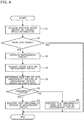
- Fig. 4 is a flowchart illustrating an example of the flow of abnormality detection processing to be executed by the terminal 30 in the vehicle air-conditioning apparatus 1 according to the present embodiment.
- the abnormality detection processing as indicated in Fig. 4 is repeatedly executed at regular intervals.
- step S1 the terminal 30 acquires position information or vehicle speed information on the train including the railway vehicle 100, from any of the vehicle-mounted communication device 41 and the central devices 42 and 43.
- vehicle speed information is also referred to as speed information.
- the position information on the train may be two-dimensional or three-dimensional position information received from a GPS, or kilometrage information on the distance from a station to the train.
- step S2 the terminal 30 determines whether or not the train is stationary based on the acquired position information or vehicle speed information.
- the "stationary" in this case means that the train is temporarily stopped during train service.
- the terminal 30 acquires position information on the train, if this acquired position information coincides with previously acquired position information, the terminal 30 can determine that the train is stationary.
- the terminal 30 acquires vehicle speed information of the train, if the vehicle speed is zero, the terminal 30 can determine that the train is stationary.
- the terminal 30 may be configured to determine that the train is stationary only when the train is stationary at any of the stations, and determine that the train is not stationary when the train is stationary at a location other than the stations.
- the terminal 30 may be configured to determine that the train is stationary whenever the train is stationary, regardless of where the train is stationary. In step S2, when the terminal 30 determines that the train is stationary, the process to be performed proceeds to step S3, and when the terminal 30 determines that the train is not stationary, the process ends.
- step S3 the terminal 30 forcibly causes the refrigerant circuits 10a and 10b to operate.
- the terminal 30 causes the refrigerant circuits 10a and 10b to start to operate, and when the refrigerant circuits 10a and 10b have already operated, the terminal 30 causes the refrigerant circuits 10a and 10b to continue to operate.
- step S4 the terminal 30 acquires state data on the refrigerant circuits 10a and 10b at the time when the train is stationary.
- the state data of the refrigerant circuits 10a and 10b includes data related to, for example, temperature, pressure, current and electric power.
- the state data on the refrigerant circuits 10a and 10b should be acquired under the same operation condition as state data on these circuits was previously acquired (for example, when the train was stationary at a previous station).
- the state data on the refrigerant circuits 10a and 10b should be acquired, with a refrigeration cycle stabilized, after the elapse of predetermined time from the start of the operation of the refrigerant circuits 10a and 10b.
- the operation of the refrigerant circuits 10a and 10b may be stopped after acquiring the state data on the refrigerant circuits 10a and 10b.
- the terminal 30 may be configured not to acquire the state data when it is detected that the train which has been stationary is started before the state data on the refrigerant circuits 10a and 10b is acquired.
- step S5 the terminal 30 determines whether or not abnormality occurs in the refrigerant circuits 10a and 10b based on the acquired state data. For example, the terminal 30 compares currently acquired state data with previously acquired state data (for example, state data acquired when the train was stationary at a previous station) acquired state data, and determines whether or not abnormality occurs in the refrigerant circuits 10a and 10b based on the result of the comparison. For example, in the case where the degree of superheat at the outlet of the evaporator and the pressures of the low-pressure sides of the refrigerant circuits decrease, as compared with those indicated in the previously acquired state data, it can be determined that clogging occurs in an expansion valve.
- previously acquired state data for example, state data acquired when the train was stationary at a previous station
- the terminal 30 may be configured to compare the acquired state data with state data acquired from a vehicle air-conditioning apparatus mounted on another vehicle in the train including the railway vehicle 100, and determine whether or not abnormality occurs in the refrigerant circuits 10a and 10b based on the result of the comparison.
- the state data on the vehicle air-conditioning apparatus mounted on the other vehicle can be, for example, acquired from any of the terminal 30, the central devices 42 and 43 and the vehicle-mounted communication device 41 of the vehicle air-conditioning apparatus mounted on the other vehicle.
- step S6 When the terminal 30 determines that abnormality occurs in the refrigerant circuits 10a and 10b (Yes in step S6), the process proceeds to step S7, and when the terminal 30 determines that abnormality does not occur (No in step S6), the process proceeds to step S8.
- the terminal 30 indicates that abnormality occurs in the refrigerant circuits 10a and 10b.
- the terminal 30 transmits information indicating what abnormality occurs in the refrigerant circuits 10a and 10b to the central devices 42 and 43.
- the central devices 42 and 43 causes respective display units provided thereat to display information indicating what abnormality occurs and in which of the vehicle air-conditioning apparatuses 1 the abnormality occurs.
- the terminal 30 may transmit the information indicating what abnormality occurs in the refrigerant circuits 10a and 10b to the ground system 50 via the vehicle-mounted communication device 41.
- the ground system 50 may cause a display unit provided thereat to display information indicating which of the trains is a train including a vehicle air-conditioning apparatus 1 that the abnormality occurs, which of the vehicle air-conditioning apparatuses 1 is the vehicle air-conditioning apparatus 1 that the abnormality occurs, and what the abnormality is.
- step S8 the terminal 30 indicates that abnormality does not occur in the refrigerant circuit 10a or the refrigerant circuit 10b.
- the terminal 30 transmits information indicating that abnormality does not occur in the refrigerant circuit 10a or the refrigerant circuit 10b to the central devices 42 and 43.
- the central devices 42 and 43 cause the display units provided thereat to display information indicating which of the vehicle air-conditioning apparatuses 1 has no abnormality.
- the terminal 30 may transmit the information indicating that abnormality does not occur in the refrigerant circuit 10a or the refrigerant circuit 10b to the ground system 50 via the vehicle-mounted communication device 41.
- the ground system 50 may be configured to cause the display unit provided thereat to display the information indicating which of the trains is a train including a vehicle air-conditioning apparatus 1 that abnormality does not occur, and which of the vehicle air-conditioning apparatuses 1 is the vehicle air-conditioning apparatus 1 that abnormality does not occur.
- the vehicle air-conditioning apparatus 1 includes the refrigerant circuits 10a and 10b, and the control unit (the terminal 30 in the present embodiment) which controls the refrigerant circuits 10a and 10b.
- the vehicle air-conditioning apparatus 1 is also mounted on the railway vehicle 100.
- the control unit determines whether or not the railway vehicle 100 is stationary based on the position information or speed information on the railway vehicle 100, causes the refrigerant circuits 10a and 10b to operate when the railway vehicle 100 is stationary, acquires state data on the refrigerant circuits 10a and 10b at the time when the railway vehicle 100 is stationary, and detects whether abnormality occurs in the refrigerant circuits 10a and 10b based on the state data.
- Vibration of the traveling railway vehicle 100 is transmitted to the vehicle air-conditioning apparatus 1. Therefore, there is a case where while the railway vehicle 100 is traveling, deterioration of each of components of the vehicle air-conditioning apparatus 1 is promoted or abnormality easily occurs in the vehicle air-conditioning apparatus 1, even when the vehicle air-conditioning apparatus 1 itself is not operated. For example, if the vibration is transmitted to the compressors 11a and 11b, there is a possibility that a rotor and a stator will collide with each other and be damaged. If the vibration is transmitted to the refrigerant pipe, there is a possibility that a joint of a refrigerant pipe will be damaged, and refrigerant will leak therefrom.
- the control unit can detect the abnormality of the refrigerant circuits 10a and 10b at an early stage. Therefore, a defective condition of the vehicle air-conditioning apparatus 1 which results from the abnormality can be corrected at an early stage.
- the operation conditions of the refrigerant circuits 10a and 10b easily vary since they are affected by wind and vibration made while the railway vehicle 100 is traveling.
- state data on the refrigerant circuits 10a and 10b which is acquired by the control unit while the railway vehicle 100 is traveling is not stable, and it is therefore hard to detect whether or not abnormality occur in the refrigerant circuits 10a and 10b.
- the vehicle air-conditioning apparatus 1 is not affected by wind or vibration which would be made while the railway vehicle 100 is traveling, and the state of the vehicle air-conditioning apparatus 1 is thus close to that of a stationary air-conditioning apparatus.
- the operation conditions of the refrigerant circuits 10a and 10b at the timing when the state data is acquired can be easily made to be the same as each other. Therefore, it is possible to improve the accuracy of detection of whether or not abnormality occurs in the refrigerant circuits 10a and 10b at least to the same level as that of the stationary type of air-conditioning apparatus, thereby preventing erroneous detection.
- control unit may be configured to compare acquired state data with previously acquired state data, and detect whether or not abnormality occurs in the refrigerant circuits 10a and 10b based on the result of the comparison. Also, the control unit may be configured to compare the acquired state data with state data acquired from a vehicle air-conditioning apparatus mounted on a vehicle other than the railway vehicle 100 (for example, another vehicle which is included in the same train as the railway vehicle 100), and detect whether or not abnormality occurs in the refrigerant circuits 10a and 10b based on the result of the comparison.
- an abnormality detection system for a vehicle air-conditioning apparatus will be described.
- abnormality in the refrigerant circuits 10a and 10b is detected by the terminal 30 of each of the vehicle air-conditioning apparatuses 1.
- abnormality in the refrigerant circuits 10a and 10b is detected by the ground system 50.
- a schematic configuration of an abnormality detection system 2 is the same as that as illustrated in Fig. 3 .
- Fig. 5 is a flowchart illustrating an example of the flow of state data acquisition processing to be executed by the terminal 30 in the abnormality detection system 2 for the vehicle air-conditioning apparatus 1 according to embodiment 2. Steps S11 to S14 as indicated in Fig. 5 are the same as steps S1 to S4 as indicated in Fig. 4 , and their descriptions will thus be omitted.
- step S15 the terminal 30 transmits state data on the refrigerant circuits 10a and 10b to the ground system 50 via the vehicle-mounted communication device 41 and the communication network 60.
- Fig. 6 is a flowchart illustrating an example of the flow of abnormality detection processing to be executed by the ground system 50 in the abnormality detection system 2 for the vehicle air-conditioning apparatus 1 according to embodiment 2.
- the ground system 50 receives state data on the refrigerant circuits 10a and 10b from a vehicle-mounted system 40 of a given train.
- the ground system 50 stores the received state data in a database 52.
- the database 52 stores state data items which are transmitted from respective vehicle-mounted systems 40a.
- step S22 the ground system 50 compares the state data received from the vehicle-mounted system 40 of the train with state data received from an vehicle-mounted system of another train (e.g., a train which travels ahead of or behind the above train), and determines whether or not abnormality occurs in the refrigerant circuits 10a and 10b based on the result of the comparison. For example, when the degree of superheat at the outlet of the evaporator and the pressures of the low-pressure sides of the refrigerant circuits lower as compared with those indicated in the state data received from the vehicle-mounted system of the other train, it can be determined that clogging occurs in in the expansion valve.
- step S23 When it is determined that abnormality occurs in the refrigerant circuits 10a and 10b (Yes in step S23), the process proceeds to step S24, and when it is determined that abnormality does not occur in the refrigerant circuit 10a or the refrigerant circuit 10b (No in step S23), the process proceeds to step S25.
- the ground system 50 indicates that abnormality occurs in the refrigerant circuits 10a and 10b.
- the ground system 50 causes the display unit provided thereat to display the information indicating which of the trains is a train including a vehicle air-conditioning apparatus 1 that abnormality occurs, which of the vehicle air-conditioning apparatuses 1 is the vehicle air-conditioning apparatus 1 that abnormality occurs, and what the abnormality is.
- the ground system 50 may transmit information indicating which of the vehicle air-conditioning apparatuses 1 is the vehicle air-conditioning apparatus 1 that abnormality occurs and what the abnormality is to the vehicle-mounted system 40 of the train on which the vehicle air-conditioning apparatus 1 that abnormality occurs is mounted.
- the vehicle-mounted system 40 upon reception of the above information, causes the display unit provided at each of the central devices 42 and 43 to display the information indicating which of the vehicle air-conditioning apparatuses 1 is the vehicle air-conditioning apparatus 1 that abnormality occurs, and what the abnormality is.
- the ground system 50 indicates that abnormality does not occur in the refrigerant circuit 10a or the refrigerant circuit 10b.
- the ground system 50 causes the display unit provided thereat to display information indicating which of the trains is a train including a vehicle air-conditioning apparatus 1 that abnormality does not occur, and which of the vehicle air-conditioning apparatuses 1 is the vehicle air-conditioning apparatus 1 that abnormality does not occur.
- the ground system 50 may transmit information indicating which of the vehicle air-conditioning apparatuses 1 is the vehicle air-conditioning apparatus 1 that abnormality does not occur to the vehicle-mounted system 40 of the train on which the vehicle air-conditioning apparatus 1 that abnormality does not occur is mounted.
- the vehicle-mounted system 40 upon reception of the above information, causes, for example, the display unit provided at each of the central devices 42 and 43 to display the information indicating which of the vehicle air-conditioning apparatuses 1 is the vehicle air-conditioning apparatus 1 that abnormality does not occur.
- the abnormality detection system 2 for the vehicle air-conditioning apparatus 1 includes: the vehicle air-conditioning apparatus 1 which includes the refrigerant circuits 10a and 10b and the control units (for example, the vehicle-mounted communication device 41, the central devices 42 and 43, and the terminal 30) which controls the refrigerant circuits 10a and 10b; and the ground system 50 connected to the control unit via the communication network 60.
- the vehicle air-conditioning apparatus 1 is mounted on the railway vehicle 100.
- the control unit of the vehicle air-conditioning apparatus 1 determines whether or not the railway vehicle 100 is stationary based on the position information or speed information on the railway vehicle 100, causes the refrigerant circuits 10a and 10b to operate when the railway vehicle 100 is stationary, acquires the state data on the refrigerant circuits 10a and 10b at the time when the railway vehicle 100 is stationary, and transmits the state data to the ground system 50.
- the ground system 50 detects whether abnormality occurs in the refrigerant circuits 10a and 10b based on the state data.
- the ground system 50 may be configured to compare the state data with state data acquired from a vehicle air-conditioning apparatus mounted on a vehicle included in a train other than the train including the railway vehicle 100, and detect whether abnormality occurs in the refrigerant circuits 10a and 10b based on the result of the comparison.
- vehicle air-conditioning apparatus abnormality detection system 10a, 10b refrigerant circuit 11a, 11b compressor 12a, 12b four-way valve 13a, 13b indoor heat exchanger 14a, 14b pressure-reducing device 15a, 15b outdoor heat exchanger 16 outdoor fan 17a, 17b indoor fan 20 outdoor chamber 21a, 21b indoor chamber 30 terminal 40 vehicle-mounted system 41 vehicle-mounted communication device 42, 43 central device 50 ground system 51 ground communication device 52 database 60 communication network 100 railway vehicle 101 compartment 102 air duct
Landscapes
- Engineering & Computer Science (AREA)
- Mechanical Engineering (AREA)
- Physics & Mathematics (AREA)
- Thermal Sciences (AREA)
- General Engineering & Computer Science (AREA)
- Air-Conditioning For Vehicles (AREA)
- Air Conditioning Control Device (AREA)
- Electric Propulsion And Braking For Vehicles (AREA)
Abstract
Description
- The present invention relates to a vehicle air-conditioning apparatus to be mounted on a vehicle, and an abnormality detection system for the vehicle air-conditioning apparatus.
-
Patent Literature 1 discloses a refrigeration cycle apparatus. In this refrigeration cycle apparatus, a calculation refrigerant amount is calculated based on an operation-state amount of a refrigerant circuit, a value obtained by correcting the calculation refrigerant amount is compared with an appropriate refrigerant amount, and it is determined whether a refrigerant amount is excess or deficient based on the result of the comparison. This determination is made at regular intervals. - Patent Literature 1: Japanese Patent No.
4975052 - A refrigeration cycle apparatus includes a stationary air-conditioning apparatus and a non-stationary air-conditioning apparatus such as a vehicle air-conditioning apparatus. In the stationary type air-conditioning apparatus, it is determined at regular intervals whether abnormality such as excess or deficiency of the amount of refrigerant occurs or not, and the abnormality can thus be detected early if it occurs.
- In contrast, in the vehicle air-conditioning apparatus, the operation conditions greatly vary in accordance with the traveling state of a vehicle. Thus, there is a case where it is hard to detect abnormality under a traveling state. Therefore, in the vehicle air-conditioning apparatus, even if it is determined at regular intervals whether abnormality occurs or not, there is a case where the abnormality cannot be detected early.
- The present invention has been made to solve the above problem, and an object of the present invention is to provide a vehicle air-conditioning apparatus and an abnormality detection system for the vehicle air-conditioning apparatus, which can detect abnormality early if it occurs.
- A vehicle air-conditioning apparatus according to an embodiment of the present invention includes a refrigerant circuit and a control unit which controls the refrigerant circuit, and is mounted on a vehicle. The control unit determines whether or not the vehicle is stationary based on position information or speed information on the vehicle, causes the refrigerant circuit to operate when the vehicle is stationary, acquires state data on the refrigerant circuit at the time when the vehicle is stationary, and detects whether abnormality occurs in the refrigerant circuit based on the state data.
- An abnormality detection system for a vehicle air-conditioning apparatus mounted on a vehicle, according to the embodiment of the present invention, includes: the vehicle air-conditioning apparatus which includes a refrigerant circuit and a control unit which controls the refrigerant circuit; and a ground system connected to the control unit via a communication network. The control unit determines whether or not the vehicle is stationary based on position information or speed information on the vehicle, causes the refrigerant circuit to operate when the vehicle is stationary, acquires state data on the refrigerant circuit at the time when the vehicle is stationary, and transmits the state data to the ground system. The ground system detects whether abnormality occurs in the refrigerant circuit based on the state data.
- According to embodiments of the present invention, it is possible to detect abnormality in a refrigerant circuit when a vehicle is stopped, even if the abnormality occurs in the refrigerant circuit while the vehicle is traveling. It is therefore possible to detect the abnormality of the refrigerant circuit at an early stage.
-
-
Fig. 1 is a schematic side view illustrating a configuration of arailway vehicle 100 on which a vehicle air-conditioning apparatus 1 according toembodiment 1 of the present invention is mounted. -
Fig. 2 is a schematic refrigerant circuit diagram illustrating a configuration of the vehicle air-conditioning apparatus 1 according toembodiment 1 of the present invention. -
Fig. 3 is a schematic block diagram illustrating a configuration of anabnormality detection system 2 for the vehicle air-conditioning apparatus 1 according toembodiment 1 of the present invention. -
Fig. 4 is a flowchart illustrating an example of the flow of abnormality detection processing to be executed by aterminal 30 in the vehicle air-conditioning apparatus 1 according toembodiment 1 of the present invention. -
Fig. 5 is a flowchart illustrating an example of the flow of state data acquisition processing to be executed by aterminal 30 in anabnormality detection system 2 for a vehicle air-conditioning apparatus 1 according toembodiment 2 of the present invention. -
Fig. 6 is a flowchart illustrating an example of the flow of abnormality detection processing to be executed by aground system 50 in theabnormality detection system 2 for the vehicle air-conditioning apparatus 1 according toembodiment 2 of the present invention. - A vehicle air-conditioning apparatus and an abnormality detection system for the vehicle air-conditioning apparatus, according to
embodiment 1 of the present invention, will be described.Fig. 1 is a schematic side view illustrating a configuration of arailway vehicle 100 on which a vehicle air-conditioning apparatus 1 according toembodiment 1 is mounted. It should be noted that in the following figures includingFig. 1 , the relationship in dimension between components and the shapes thereof may be different from those of actual components. - As illustrated in
Fig. 1 , the vehicle air-conditioning apparatus 1 is mounted on a roof of therailway vehicle 100. Anair duct 102 is provided in a ceiling of acompartment 101 in therailway vehicle 100. From the vehicle air-conditioning apparatus 1, air for air-conditioning is made to blow into thecompartment 101 through theair duct 102. Then, air in thecompartment 101 is sucked into the vehicle air-conditioning apparatus 1 through a return air duct (not illustrated). It should be noted that the vehicle air-conditioning apparatus 1 of the present embodiment is mounted on the roof of therailway vehicle 100, but it may be mounted under a floor of therailway vehicle 100. - The
railway vehicle 100 forms part or the whole of a single train. In other words, a single train is made up of at least onerailway vehicle 100. In asingle railway vehicle 100, one or more vehicle air-conditioning apparatuses 1 are mounted. -
Fig. 2 is a schematic refrigerant circuit diagram illustrating a configuration of the vehicle air-conditioning apparatus 1. As illustrated inFig. 2 , the vehicle air-conditioning apparatus 1 includes, for example, tworefrigerant circuits conditioning apparatus 1 includes anoutdoor chamber 20, andindoor chambers outdoor chamber 20 in the longitudinal direction of therailway vehicle 100, with theoutdoor chamber 20 interposed between theindoor chambers - In a configuration of the
refrigerant circuit 10a, acompressor 11a, a four-way valve 12a, anindoor heat exchanger 13a, a pressure-reducingdevice 14a (for example, a linear electronic expansion valve) and anoutdoor heat exchanger 15a are connected by refrigerant pipes. During a heating operation, thecompressor 11a, theindoor heat exchanger 13a, the pressure-reducingdevice 14a and theoutdoor heat exchanger 15a are connected in this order. Thereby, theindoor heat exchanger 13a functions as a condenser, and theoutdoor heat exchanger 15a functions as an evaporator. During a cooling operation, a refrigerant flow path is switched by the four-way valve 12a, and thecompressor 11a, theoutdoor heat exchanger 15a, the pressure-reducingdevice 14a and theindoor heat exchanger 13a are connected in this order. Thereby, theindoor heat exchanger 13a functions as an evaporator, and theoutdoor heat exchanger 15a functions as a condenser. Thecompressor 11a, the four-way valve 12a, the pressure-reducingdevice 14a and theoutdoor heat exchanger 15a are provided in theoutdoor chamber 20. Theindoor heat exchanger 13a is provided in theindoor chamber 21a. - Similarly, in a configuration of the
refrigerant circuit 10b, acompressor 11b, a four-way valve 12b, anindoor heat exchanger 13b, a pressure-reducingdevice 14b (for example, a linear electronic expansion valve) and anoutdoor heat exchanger 15b are connected by refrigerant pipes. Thecompressor 11b, the four-way valve 12b, the pressure-reducingdevice 14b and theoutdoor heat exchanger 15b are provided in theoutdoor chamber 20. Theindoor heat exchanger 13b is provided in theindoor chamber 21b. - In the
outdoor chamber 20, anoutdoor fan 16 which sends outdoor air to theoutdoor heat exchangers indoor chamber 21a, anindoor fan 17a which sends indoor air to theindoor heat exchanger 13a is provided. Indoor air which has passed through theindoor heat exchanger 13a and exchanged heat with the refrigerant is supplied to, for example, a front portion of the vehicle which is located in thecompartment 101. In theindoor chamber 21b, anindoor fan 17b which sends indoor air to theindoor heat exchanger 13b is provided. Indoor air which has passed through theindoor heat exchanger 13b and exchanged heat with refrigerant is supplied to, for example, a rear portion of the vehicle which is located in thecompartment 101. - The vehicle air-
conditioning apparatus 1 includes aterminal 30 as a controller. Theterminal 30 includes a microcomputer provided with a CPU, a ROM, a RAM, an I/O port, etc. Theterminal 30 controls the operations of theentire refrigerant circuits compressors outdoor fan 16, and theindoor fans terminal 30 functions as a controller of the vehicle air-conditioning apparatus 1, and forms part of anabnormality detection system 2, which will be described later. In the present embodiment, air-conditioning apparatuses 1 includerespective terminals 30, but therefrigerant circuits respective terminals 30. -
Fig. 3 is a schematic block diagram illustrating a configuration of the cloggingdetection system 2 for the vehicle air-conditioning apparatus 1, according to the present embodiment. As illustrated inFig. 3 , theabnormality detection system 2 includes at least one vehicle-mountedsystem 40, and aground system 50 which is connected to the vehicle-mountedsystem 40 via acommunication network 60. Thecommunication network 60 is a communication network using a wireless communication such as a mobile phone, a wireless LAN, WiMAX (registered trademark) or a millimeter wave. - The vehicle-mounted
system 40 is mounted on a train ofrailway vehicles 100. One vehicle-mountedsystem 40 is typically mounted on one train. The vehicle-mountedsystem 40 includes a vehicle-mountedcommunication device 41 which communicates with theground system 50 via thecommunication network 60,central devices railway vehicles 100, which are located at front and rear ends of the train, and a plurality ofterminals 30 provided, for example, in respective vehicle air-conditioning apparatuses 1. The vehicle-mountedcommunication device 41, thecentral devices terminals 30 function as controllers which control the vehicle air-conditioning apparatuses 1 mounted on the train. - The
ground system 50 includes aground communication device 51 which communicates with the vehicle-mountedsystem 40 via thecommunication network 60, adatabase 52 which stores data received from the vehicle-mountedsystem 40, and a controller (not illustrated) which controls theground communication device 51 and thedatabase 52. Theground system 50 transmits and receives data to and from at least one vehicle-mountedsystem 40 via thecommunication network 60 to remotely monitor each of the vehicle air-conditioning apparatuses 1. -
Fig. 4 is a flowchart illustrating an example of the flow of abnormality detection processing to be executed by the terminal 30 in the vehicle air-conditioning apparatus 1 according to the present embodiment. The abnormality detection processing as indicated inFig. 4 is repeatedly executed at regular intervals. - In step S1 as indicated in
Fig. 4 , the terminal 30 acquires position information or vehicle speed information on the train including therailway vehicle 100, from any of the vehicle-mountedcommunication device 41 and thecentral devices - In step S2, the terminal 30 determines whether or not the train is stationary based on the acquired position information or vehicle speed information. The "stationary" in this case means that the train is temporarily stopped during train service. In the case where the terminal 30 acquires position information on the train, if this acquired position information coincides with previously acquired position information, the terminal 30 can determine that the train is stationary. In the case where the terminal 30 acquires vehicle speed information of the train, if the vehicle speed is zero, the terminal 30 can determine that the train is stationary. In the case where the terminal 30 stores position information on stations at which the train will be stopped, the terminal 30 may be configured to determine that the train is stationary only when the train is stationary at any of the stations, and determine that the train is not stationary when the train is stationary at a location other than the stations. Alternatively, the terminal 30 may be configured to determine that the train is stationary whenever the train is stationary, regardless of where the train is stationary. In step S2, when the terminal 30 determines that the train is stationary, the process to be performed proceeds to step S3, and when the terminal 30 determines that the train is not stationary, the process ends.
- In step S3, the terminal 30 forcibly causes the
refrigerant circuits refrigerant circuits refrigerant circuits refrigerant circuits refrigerant circuits - In step S4, the terminal 30 acquires state data on the
refrigerant circuits refrigerant circuits indoor heat exchangers refrigerant circuits outdoor fan 16 and theindoor fans compressors compressors refrigerant circuits refrigerant circuits refrigerant circuits refrigerant circuits refrigerant circuits refrigerant circuits refrigerant circuits - In step S5, the terminal 30 determines whether or not abnormality occurs in the
refrigerant circuits refrigerant circuits - The terminal 30 may be configured to compare the acquired state data with state data acquired from a vehicle air-conditioning apparatus mounted on another vehicle in the train including the
railway vehicle 100, and determine whether or not abnormality occurs in therefrigerant circuits central devices communication device 41 of the vehicle air-conditioning apparatus mounted on the other vehicle. - When the terminal 30 determines that abnormality occurs in the
refrigerant circuits - In step S7, the terminal 30 indicates that abnormality occurs in the
refrigerant circuits refrigerant circuits central devices central devices conditioning apparatuses 1 the abnormality occurs. The terminal 30 may transmit the information indicating what abnormality occurs in therefrigerant circuits ground system 50 via the vehicle-mountedcommunication device 41. Theground system 50 may cause a display unit provided thereat to display information indicating which of the trains is a train including a vehicle air-conditioning apparatus 1 that the abnormality occurs, which of the vehicle air-conditioning apparatuses 1 is the vehicle air-conditioning apparatus 1 that the abnormality occurs, and what the abnormality is. - In step S8, the terminal 30 indicates that abnormality does not occur in the
refrigerant circuit 10a or therefrigerant circuit 10b. For example, the terminal 30 transmits information indicating that abnormality does not occur in therefrigerant circuit 10a or therefrigerant circuit 10b to thecentral devices central devices conditioning apparatuses 1 has no abnormality. The terminal 30 may transmit the information indicating that abnormality does not occur in therefrigerant circuit 10a or therefrigerant circuit 10b to theground system 50 via the vehicle-mountedcommunication device 41. Theground system 50 may be configured to cause the display unit provided thereat to display the information indicating which of the trains is a train including a vehicle air-conditioning apparatus 1 that abnormality does not occur, and which of the vehicle air-conditioning apparatuses 1 is the vehicle air-conditioning apparatus 1 that abnormality does not occur. - As described above, the vehicle air-
conditioning apparatus 1 according to the present embodiment includes therefrigerant circuits refrigerant circuits conditioning apparatus 1 is also mounted on therailway vehicle 100. The control unit determines whether or not therailway vehicle 100 is stationary based on the position information or speed information on therailway vehicle 100, causes therefrigerant circuits railway vehicle 100 is stationary, acquires state data on therefrigerant circuits railway vehicle 100 is stationary, and detects whether abnormality occurs in therefrigerant circuits - Vibration of the traveling
railway vehicle 100 is transmitted to the vehicle air-conditioning apparatus 1. Therefore, there is a case where while therailway vehicle 100 is traveling, deterioration of each of components of the vehicle air-conditioning apparatus 1 is promoted or abnormality easily occurs in the vehicle air-conditioning apparatus 1, even when the vehicle air-conditioning apparatus 1 itself is not operated. For example, if the vibration is transmitted to thecompressors compressors compressors refrigerant circuits compressors compressors - In the present embodiment, even if abnormality occurs in the
refrigerant circuits railway vehicle 100 is traveling, it is possible to detect the abnormality in therefrigerant circuits railway vehicle 100 is stopped at a station or the like. Therefore, according to the present embodiment, the control unit can detect the abnormality of therefrigerant circuits conditioning apparatus 1 which results from the abnormality can be corrected at an early stage. - While the
railway vehicle 100 is traveling, the operation conditions of therefrigerant circuits railway vehicle 100 is traveling. Thus, state data on therefrigerant circuits railway vehicle 100 is traveling is not stable, and it is therefore hard to detect whether or not abnormality occur in therefrigerant circuits railway vehicle 100 is stationary, the vehicle air-conditioning apparatus 1 is not affected by wind or vibration which would be made while therailway vehicle 100 is traveling, and the state of the vehicle air-conditioning apparatus 1 is thus close to that of a stationary air-conditioning apparatus. Therefore, by acquiring the state date on therefrigerant circuits railway vehicle 100 is stationary, the operation conditions of therefrigerant circuits refrigerant circuits - In the vehicle air-
conditioning apparatus 1 according to the present embodiment, the control unit may be configured to compare acquired state data with previously acquired state data, and detect whether or not abnormality occurs in therefrigerant circuits refrigerant circuits - An abnormality detection system for a vehicle air-conditioning apparatus according to
embodiment 2 of the present invention will be described. Inembodiment 1 described above, abnormality in therefrigerant circuits terminal 30 of each of the vehicle air-conditioning apparatuses 1. In contrast, inembodiment 2, abnormality in therefrigerant circuits ground system 50. A schematic configuration of anabnormality detection system 2 is the same as that as illustrated inFig. 3 . -
Fig. 5 is a flowchart illustrating an example of the flow of state data acquisition processing to be executed by the terminal 30 in theabnormality detection system 2 for the vehicle air-conditioning apparatus 1 according toembodiment 2. Steps S11 to S14 as indicated inFig. 5 are the same as steps S1 to S4 as indicated inFig. 4 , and their descriptions will thus be omitted. - In step S15, the terminal 30 transmits state data on the
refrigerant circuits ground system 50 via the vehicle-mountedcommunication device 41 and thecommunication network 60. -
Fig. 6 is a flowchart illustrating an example of the flow of abnormality detection processing to be executed by theground system 50 in theabnormality detection system 2 for the vehicle air-conditioning apparatus 1 according toembodiment 2. In step S21 as indicated inFig. 6 , theground system 50 receives state data on therefrigerant circuits system 40 of a given train. Theground system 50 stores the received state data in adatabase 52. Thedatabase 52 stores state data items which are transmitted from respective vehicle-mounted systems 40a. - In step S22, the
ground system 50 compares the state data received from the vehicle-mountedsystem 40 of the train with state data received from an vehicle-mounted system of another train (e.g., a train which travels ahead of or behind the above train), and determines whether or not abnormality occurs in therefrigerant circuits - When it is determined that abnormality occurs in the
refrigerant circuits refrigerant circuit 10a or therefrigerant circuit 10b (No in step S23), the process proceeds to step S25. - In step S24, the
ground system 50 indicates that abnormality occurs in therefrigerant circuits ground system 50 causes the display unit provided thereat to display the information indicating which of the trains is a train including a vehicle air-conditioning apparatus 1 that abnormality occurs, which of the vehicle air-conditioning apparatuses 1 is the vehicle air-conditioning apparatus 1 that abnormality occurs, and what the abnormality is. Theground system 50 may transmit information indicating which of the vehicle air-conditioning apparatuses 1 is the vehicle air-conditioning apparatus 1 that abnormality occurs and what the abnormality is to the vehicle-mountedsystem 40 of the train on which the vehicle air-conditioning apparatus 1 that abnormality occurs is mounted. In this case, upon reception of the above information, the vehicle-mountedsystem 40 causes the display unit provided at each of thecentral devices conditioning apparatuses 1 is the vehicle air-conditioning apparatus 1 that abnormality occurs, and what the abnormality is. - In step S25, the
ground system 50 indicates that abnormality does not occur in therefrigerant circuit 10a or therefrigerant circuit 10b. For example, theground system 50 causes the display unit provided thereat to display information indicating which of the trains is a train including a vehicle air-conditioning apparatus 1 that abnormality does not occur, and which of the vehicle air-conditioning apparatuses 1 is the vehicle air-conditioning apparatus 1 that abnormality does not occur. Theground system 50 may transmit information indicating which of the vehicle air-conditioning apparatuses 1 is the vehicle air-conditioning apparatus 1 that abnormality does not occur to the vehicle-mountedsystem 40 of the train on which the vehicle air-conditioning apparatus 1 that abnormality does not occur is mounted. In this case, upon reception of the above information, the vehicle-mountedsystem 40 causes, for example, the display unit provided at each of thecentral devices conditioning apparatuses 1 is the vehicle air-conditioning apparatus 1 that abnormality does not occur. - As described above, the
abnormality detection system 2 for the vehicle air-conditioning apparatus 1 according toembodiment 2 includes: the vehicle air-conditioning apparatus 1 which includes therefrigerant circuits communication device 41, thecentral devices refrigerant circuits ground system 50 connected to the control unit via thecommunication network 60. The vehicle air-conditioning apparatus 1 is mounted on therailway vehicle 100. The control unit of the vehicle air-conditioning apparatus 1 determines whether or not therailway vehicle 100 is stationary based on the position information or speed information on therailway vehicle 100, causes therefrigerant circuits railway vehicle 100 is stationary, acquires the state data on therefrigerant circuits railway vehicle 100 is stationary, and transmits the state data to theground system 50. Theground system 50 detects whether abnormality occurs in therefrigerant circuits - According to
embodiment 2, it is possible to detect abnormality in therefrigerant circuits embodiment 1. - In the
abnormality detection system 2 for the vehicle air-conditioning apparatus 1 according toembodiment 2, theground system 50 may be configured to compare the state data with state data acquired from a vehicle air-conditioning apparatus mounted on a vehicle included in a train other than the train including therailway vehicle 100, and detect whether abnormality occurs in therefrigerant circuits - The above embodiments and modifications can be combined and put to practical use.
- 1 vehicle air-
conditioning apparatus 2abnormality detection system refrigerant circuit 11b compressor way valve indoor heat exchanger device outdoor heat exchanger 16outdoor fan indoor fan 20outdoor chamber indoor chamber 30terminal 40 vehicle-mountedsystem 41 vehicle-mountedcommunication device central device 50ground system 51ground communication device 52database 60communication network 100railway vehicle 101compartment 102 air duct
Claims (5)
- A vehicle air-conditioning apparatus mounted on a vehicle, comprising:a refrigerant circuit; anda control unit configured to control the refrigerant circuit,wherein the control unit is configured to determine whether the vehicle is stationary based on position information or speed information on the vehicle, cause the refrigerant circuit to operate when the vehicle is stationary, acquire state data on the refrigerant circuit at time when the vehicle is stationary, and detect whether abnormality occurs in the refrigerant circuit based on the state data.
- The vehicle air-conditioning apparatus of claim 1, wherein
the control unit is configured to compare the state data with previously acquired state data, and detect whether abnormality occurs in the refrigerant circuit based on a result of comparison. - The vehicle air-conditioning apparatus of claim 1, wherein
the control unit is configured to compare the state data with state data acquired from a vehicle air-conditioning apparatus mounted on a vehicle other than the vehicle, and detect whether abnormality occurs in the refrigerant circuit based on a result of comparison. - An abnormality detection system for a vehicle air-conditioning apparatus which is mounted on a vehicle, and which includes a refrigerant circuit and a control unit configured to control the refrigerant circuit, the abnormality detection system comprising:the vehicle air-conditioning apparatus; anda ground system connected to the control unit via a communication network,wherein the control unit is configured to determine whether or not the vehicle is stationary based on position information or speed information on the vehicle, cause the refrigerant circuit to operate when the vehicle is stationary, acquire state data on the refrigerant circuit at time when the vehicle is stationary, and transmit the state data to the ground system, andthe ground system is configured to detect whether or not abnormality occur in the refrigerant circuit based on the state data.
- The abnormality detection system of claim 4, wherein
the ground system is configured to compare the state data with state data acquired from a vehicle air-conditioning apparatus mounted on an other vehicle which is included in a train other than a train including the vehicle, and detect whether or not abnormality occurs in the refrigerant circuit based on a result of comparison.
Applications Claiming Priority (1)
| Application Number | Priority Date | Filing Date | Title |
|---|---|---|---|
| PCT/JP2016/067342 WO2017212631A1 (en) | 2016-06-10 | 2016-06-10 | Vehicle air-conditioning device and abnormality detection system for vehicle air-conditioning device |
Publications (3)
| Publication Number | Publication Date |
|---|---|
| EP3470293A1 true EP3470293A1 (en) | 2019-04-17 |
| EP3470293A4 EP3470293A4 (en) | 2019-06-19 |
| EP3470293B1 EP3470293B1 (en) | 2021-09-08 |
Family
ID=60579009
Family Applications (1)
| Application Number | Title | Priority Date | Filing Date |
|---|---|---|---|
| EP16904665.3A Active EP3470293B1 (en) | 2016-06-10 | 2016-06-10 | Vehicle air-conditioning apparatus |
Country Status (5)
| Country | Link |
|---|---|
| US (1) | US10913326B2 (en) |
| EP (1) | EP3470293B1 (en) |
| JP (1) | JP6567184B2 (en) |
| CN (1) | CN109219552B (en) |
| WO (1) | WO2017212631A1 (en) |
Families Citing this family (3)
| Publication number | Priority date | Publication date | Assignee | Title |
|---|---|---|---|---|
| CN109311489B (en) * | 2016-06-10 | 2021-08-10 | 三菱电机株式会社 | Air conditioner for vehicle and jam detection system for air conditioner for vehicle |
| WO2020255454A1 (en) | 2019-06-20 | 2020-12-24 | 三菱電機株式会社 | Vehicular air-conditioning device |
| WO2022013937A1 (en) * | 2020-07-14 | 2022-01-20 | 株式会社日立製作所 | Railroad car |
Family Cites Families (26)
| Publication number | Priority date | Publication date | Assignee | Title |
|---|---|---|---|---|
| US5623426A (en) * | 1994-02-23 | 1997-04-22 | Sanyo Electric Co., Ltd. | Failure diagnosing system for absorption chillers |
| FR2772310B1 (en) | 1997-12-17 | 2000-02-11 | Chausson Service | METHOD AND DEVICE FOR DIAGNOSING A MOTOR VEHICLE AIR CONDITIONING LOOP |
| JPH11245807A (en) * | 1998-03-02 | 1999-09-14 | Mitsubishi Electric Corp | Vehicle air conditioning system |
| JP2000006802A (en) * | 1998-06-19 | 2000-01-11 | Hitachi Ltd | Failure diagnosis method for railcar air conditioner |
| DE19935269C1 (en) * | 1999-07-27 | 2001-01-25 | Daimler Chrysler Ag | Refrigerant filling level monitoring method for automobile air-conditioning device uses temperature difference between measured temperature at refrigerant compressor and calculated temperature value |
| US20040083744A1 (en) | 2002-11-04 | 2004-05-06 | Visteon Global Technologies, Inc. | Low-charge leak detection strategy for dual automatic temperature control system |
| JP2006010176A (en) * | 2004-06-24 | 2006-01-12 | Mitsubishi Heavy Ind Ltd | Refrigerant leakage detection control of vehicular air conditioner |
| CN101274636A (en) * | 2007-03-26 | 2008-10-01 | 林贵生 | Vehicle-mounted intelligent supervising and early warning device for running status of track traffic vehicle |
| ES2550603T3 (en) * | 2008-06-11 | 2015-11-11 | Mitsubishi Electric Corporation | Air conditioner for vehicle use, vehicle air conditioning management system, and vehicle air conditioning management method |
| JP5040887B2 (en) * | 2008-10-17 | 2012-10-03 | 三菱電機株式会社 | Vehicle air conditioning management system |
| DE102008037485B4 (en) | 2008-10-27 | 2010-09-02 | Webasto Ag | A method of evaluating operational data from a plurality of similar vehicle ancillary devices |
| US20100174412A1 (en) * | 2009-01-06 | 2010-07-08 | Lg Electronics Inc. | Air conditioner and method for detecting malfunction thereof |
| JP4975052B2 (en) | 2009-03-30 | 2012-07-11 | 三菱電機株式会社 | Refrigeration cycle equipment |
| US8892277B2 (en) * | 2009-07-22 | 2014-11-18 | Mitsubishi Electric Corporation | Vehicle air-conditioning control method |
| CN103733006B (en) * | 2011-07-29 | 2015-12-09 | 大金工业株式会社 | Transport refrigeration unit |
| US20150184880A1 (en) * | 2012-10-25 | 2015-07-02 | Mitsubishi Electric Corporation | Monitoring system |
| JP6073651B2 (en) * | 2012-11-09 | 2017-02-01 | サンデンホールディングス株式会社 | Air conditioner for vehicles |
| US9829230B2 (en) * | 2013-02-28 | 2017-11-28 | Mitsubishi Electric Corporation | Air conditioning apparatus |
| JP6012542B2 (en) * | 2013-05-21 | 2016-10-25 | 三菱電機株式会社 | On-vehicle system, train communication system, and train communication method |
| EP3023716B1 (en) * | 2013-07-18 | 2022-05-18 | Hangzhou Sanhua Research Institute Co., Ltd. | Method for controlling vehicle air-conditioning system, and vehicle air-conditioning system |
| EP3023276B1 (en) * | 2013-07-18 | 2020-01-01 | Hangzhou Sanhua Research Institute Co., Ltd. | Method for controlling degree of superheat of vehicle air-conditioning system, and vehicle air-conditioning system |
| JP6297817B2 (en) * | 2013-11-08 | 2018-03-20 | 東日本旅客鉄道株式会社 | Maintenance time determination method for vehicle air conditioner |
| KR101497048B1 (en) * | 2013-12-11 | 2015-02-27 | 서울메트로 | Simulation System for heating and cooling of rolling stock |
| US9302565B2 (en) * | 2014-06-09 | 2016-04-05 | Ford Global Technologies, Llc | Circulation for pressure loss event |
| CN104385875A (en) * | 2014-11-11 | 2015-03-04 | 无锡悟莘科技有限公司 | Intelligent auxiliary control system of automobile air conditioner |
| CN105946504A (en) * | 2016-05-05 | 2016-09-21 | 上汽通用汽车有限公司 | Method and device for controlling running modes of vehicle-mounted air conditioner |
-
2016
- 2016-06-10 US US16/306,416 patent/US10913326B2/en active Active
- 2016-06-10 CN CN201680086423.7A patent/CN109219552B/en active Active
- 2016-06-10 WO PCT/JP2016/067342 patent/WO2017212631A1/en not_active Ceased
- 2016-06-10 JP JP2018522275A patent/JP6567184B2/en active Active
- 2016-06-10 EP EP16904665.3A patent/EP3470293B1/en active Active
Also Published As
| Publication number | Publication date |
|---|---|
| US20200189358A1 (en) | 2020-06-18 |
| CN109219552A (en) | 2019-01-15 |
| JPWO2017212631A1 (en) | 2018-12-13 |
| JP6567184B2 (en) | 2019-08-28 |
| CN109219552B (en) | 2021-04-13 |
| EP3470293A4 (en) | 2019-06-19 |
| EP3470293B1 (en) | 2021-09-08 |
| US10913326B2 (en) | 2021-02-09 |
| WO2017212631A1 (en) | 2017-12-14 |
Similar Documents
| Publication | Publication Date | Title |
|---|---|---|
| US10996007B2 (en) | Vehicle air-conditioning apparatus and clogging detection system for vehicle air-conditioning apparatus | |
| US10654494B2 (en) | Vehicle air-conditioning device and train communication system | |
| EP4692690A2 (en) | Refrigerant system for cooling electronics | |
| US11260728B2 (en) | Distributed hazard detection system for a transport refrigeration system | |
| US10816248B2 (en) | Refrigeration cycle apparatus | |
| KR101496599B1 (en) | Heat source apparatus | |
| US9121624B2 (en) | Information transfer system for refrigeration air-conditioning apparatus | |
| CN107560085B (en) | Minimum operation frequency control method and control device for air conditioner compressor | |
| EP3470293B1 (en) | Vehicle air-conditioning apparatus | |
| JP7040420B2 (en) | Failure analysis system, failure analysis device | |
| RU2014137805A (en) | FIRE EXTINGUISHING SYSTEM FOR HEATING, VENTILATION AND AIR CONDITIONING VEHICLES | |
| CN105066258A (en) | Split Floor Air Conditioner | |
| JP6180094B2 (en) | On-vehicle monitoring device, ground equipment, and vehicle air conditioning system | |
| HK40000490A (en) | Vehicle air-conditioning device and abnormality detection system for vehicle air-conditioning device | |
| HK40000490B (en) | Vehicle air-conditioning device and abnormality detection system for vehicle air-conditioning device | |
| EP3591317A3 (en) | Lubricant quality management for a compressor | |
| HK40001526A (en) | Vehicle air-conditioning device and obstruction detection system for vehicle air-conditioning device | |
| HK40001526B (en) | Vehicle air-conditioning device and obstruction detection system for vehicle air-conditioning device | |
| HK40001524A (en) | Vehicle air-conditioning device and railroad-car communication system | |
| HK40001524B (en) | Vehicle air-conditioning device and railroad-car communication system | |
| JP2016169904A (en) | Operating condition management device |
Legal Events
| Date | Code | Title | Description |
|---|---|---|---|
| STAA | Information on the status of an ep patent application or granted ep patent |
Free format text: STATUS: THE INTERNATIONAL PUBLICATION HAS BEEN MADE |
|
| PUAI | Public reference made under article 153(3) epc to a published international application that has entered the european phase |
Free format text: ORIGINAL CODE: 0009012 |
|
| STAA | Information on the status of an ep patent application or granted ep patent |
Free format text: STATUS: REQUEST FOR EXAMINATION WAS MADE |
|
| 17P | Request for examination filed |
Effective date: 20181127 |
|
| AK | Designated contracting states |
Kind code of ref document: A1 Designated state(s): AL AT BE BG CH CY CZ DE DK EE ES FI FR GB GR HR HU IE IS IT LI LT LU LV MC MK MT NL NO PL PT RO RS SE SI SK SM TR |
|
| AX | Request for extension of the european patent |
Extension state: BA ME |
|
| A4 | Supplementary search report drawn up and despatched |
Effective date: 20190517 |
|
| RIC1 | Information provided on ipc code assigned before grant |
Ipc: B61D 27/00 20060101AFI20190513BHEP Ipc: B60H 1/32 20060101ALI20190513BHEP Ipc: F25B 49/02 20060101ALI20190513BHEP Ipc: B60H 1/00 20060101ALI20190513BHEP |
|
| DAV | Request for validation of the european patent (deleted) | ||
| DAX | Request for extension of the european patent (deleted) | ||
| STAA | Information on the status of an ep patent application or granted ep patent |
Free format text: STATUS: EXAMINATION IS IN PROGRESS |
|
| 17Q | First examination report despatched |
Effective date: 20200124 |
|
| GRAP | Despatch of communication of intention to grant a patent |
Free format text: ORIGINAL CODE: EPIDOSNIGR1 |
|
| STAA | Information on the status of an ep patent application or granted ep patent |
Free format text: STATUS: GRANT OF PATENT IS INTENDED |
|
| INTG | Intention to grant announced |
Effective date: 20210330 |
|
| GRAS | Grant fee paid |
Free format text: ORIGINAL CODE: EPIDOSNIGR3 |
|
| GRAA | (expected) grant |
Free format text: ORIGINAL CODE: 0009210 |
|
| STAA | Information on the status of an ep patent application or granted ep patent |
Free format text: STATUS: THE PATENT HAS BEEN GRANTED |
|
| AK | Designated contracting states |
Kind code of ref document: B1 Designated state(s): AL AT BE BG CH CY CZ DE DK EE ES FI FR GB GR HR HU IE IS IT LI LT LU LV MC MK MT NL NO PL PT RO RS SE SI SK SM TR |
|
| REG | Reference to a national code |
Ref country code: GB Ref legal event code: FG4D |
|
| REG | Reference to a national code |
Ref country code: CH Ref legal event code: EP Ref country code: AT Ref legal event code: REF Ref document number: 1428342 Country of ref document: AT Kind code of ref document: T Effective date: 20210915 |
|
| REG | Reference to a national code |
Ref country code: DE Ref legal event code: R096 Ref document number: 602016063604 Country of ref document: DE |
|
| REG | Reference to a national code |
Ref country code: IE Ref legal event code: FG4D |
|
| REG | Reference to a national code |
Ref country code: LT Ref legal event code: MG9D |
|
| REG | Reference to a national code |
Ref country code: NL Ref legal event code: MP Effective date: 20210908 |
|
| PG25 | Lapsed in a contracting state [announced via postgrant information from national office to epo] |
Ref country code: LT Free format text: LAPSE BECAUSE OF FAILURE TO SUBMIT A TRANSLATION OF THE DESCRIPTION OR TO PAY THE FEE WITHIN THE PRESCRIBED TIME-LIMIT Effective date: 20210908 Ref country code: BG Free format text: LAPSE BECAUSE OF FAILURE TO SUBMIT A TRANSLATION OF THE DESCRIPTION OR TO PAY THE FEE WITHIN THE PRESCRIBED TIME-LIMIT Effective date: 20211208 Ref country code: NO Free format text: LAPSE BECAUSE OF FAILURE TO SUBMIT A TRANSLATION OF THE DESCRIPTION OR TO PAY THE FEE WITHIN THE PRESCRIBED TIME-LIMIT Effective date: 20211208 Ref country code: ES Free format text: LAPSE BECAUSE OF FAILURE TO SUBMIT A TRANSLATION OF THE DESCRIPTION OR TO PAY THE FEE WITHIN THE PRESCRIBED TIME-LIMIT Effective date: 20210908 Ref country code: FI Free format text: LAPSE BECAUSE OF FAILURE TO SUBMIT A TRANSLATION OF THE DESCRIPTION OR TO PAY THE FEE WITHIN THE PRESCRIBED TIME-LIMIT Effective date: 20210908 Ref country code: HR Free format text: LAPSE BECAUSE OF FAILURE TO SUBMIT A TRANSLATION OF THE DESCRIPTION OR TO PAY THE FEE WITHIN THE PRESCRIBED TIME-LIMIT Effective date: 20210908 Ref country code: SE Free format text: LAPSE BECAUSE OF FAILURE TO SUBMIT A TRANSLATION OF THE DESCRIPTION OR TO PAY THE FEE WITHIN THE PRESCRIBED TIME-LIMIT Effective date: 20210908 Ref country code: RS Free format text: LAPSE BECAUSE OF FAILURE TO SUBMIT A TRANSLATION OF THE DESCRIPTION OR TO PAY THE FEE WITHIN THE PRESCRIBED TIME-LIMIT Effective date: 20210908 |
|
| REG | Reference to a national code |
Ref country code: AT Ref legal event code: MK05 Ref document number: 1428342 Country of ref document: AT Kind code of ref document: T Effective date: 20210908 |
|
| PG25 | Lapsed in a contracting state [announced via postgrant information from national office to epo] |
Ref country code: LV Free format text: LAPSE BECAUSE OF FAILURE TO SUBMIT A TRANSLATION OF THE DESCRIPTION OR TO PAY THE FEE WITHIN THE PRESCRIBED TIME-LIMIT Effective date: 20210908 Ref country code: GR Free format text: LAPSE BECAUSE OF FAILURE TO SUBMIT A TRANSLATION OF THE DESCRIPTION OR TO PAY THE FEE WITHIN THE PRESCRIBED TIME-LIMIT Effective date: 20211209 |
|
| PG25 | Lapsed in a contracting state [announced via postgrant information from national office to epo] |
Ref country code: AT Free format text: LAPSE BECAUSE OF FAILURE TO SUBMIT A TRANSLATION OF THE DESCRIPTION OR TO PAY THE FEE WITHIN THE PRESCRIBED TIME-LIMIT Effective date: 20210908 |
|
| PG25 | Lapsed in a contracting state [announced via postgrant information from national office to epo] |
Ref country code: IS Free format text: LAPSE BECAUSE OF FAILURE TO SUBMIT A TRANSLATION OF THE DESCRIPTION OR TO PAY THE FEE WITHIN THE PRESCRIBED TIME-LIMIT Effective date: 20220108 Ref country code: SM Free format text: LAPSE BECAUSE OF FAILURE TO SUBMIT A TRANSLATION OF THE DESCRIPTION OR TO PAY THE FEE WITHIN THE PRESCRIBED TIME-LIMIT Effective date: 20210908 Ref country code: SK Free format text: LAPSE BECAUSE OF FAILURE TO SUBMIT A TRANSLATION OF THE DESCRIPTION OR TO PAY THE FEE WITHIN THE PRESCRIBED TIME-LIMIT Effective date: 20210908 Ref country code: RO Free format text: LAPSE BECAUSE OF FAILURE TO SUBMIT A TRANSLATION OF THE DESCRIPTION OR TO PAY THE FEE WITHIN THE PRESCRIBED TIME-LIMIT Effective date: 20210908 Ref country code: PT Free format text: LAPSE BECAUSE OF FAILURE TO SUBMIT A TRANSLATION OF THE DESCRIPTION OR TO PAY THE FEE WITHIN THE PRESCRIBED TIME-LIMIT Effective date: 20220110 Ref country code: PL Free format text: LAPSE BECAUSE OF FAILURE TO SUBMIT A TRANSLATION OF THE DESCRIPTION OR TO PAY THE FEE WITHIN THE PRESCRIBED TIME-LIMIT Effective date: 20210908 Ref country code: NL Free format text: LAPSE BECAUSE OF FAILURE TO SUBMIT A TRANSLATION OF THE DESCRIPTION OR TO PAY THE FEE WITHIN THE PRESCRIBED TIME-LIMIT Effective date: 20210908 Ref country code: EE Free format text: LAPSE BECAUSE OF FAILURE TO SUBMIT A TRANSLATION OF THE DESCRIPTION OR TO PAY THE FEE WITHIN THE PRESCRIBED TIME-LIMIT Effective date: 20210908 Ref country code: CZ Free format text: LAPSE BECAUSE OF FAILURE TO SUBMIT A TRANSLATION OF THE DESCRIPTION OR TO PAY THE FEE WITHIN THE PRESCRIBED TIME-LIMIT Effective date: 20210908 Ref country code: AL Free format text: LAPSE BECAUSE OF FAILURE TO SUBMIT A TRANSLATION OF THE DESCRIPTION OR TO PAY THE FEE WITHIN THE PRESCRIBED TIME-LIMIT Effective date: 20210908 |
|
| REG | Reference to a national code |
Ref country code: DE Ref legal event code: R097 Ref document number: 602016063604 Country of ref document: DE |
|
| PLBE | No opposition filed within time limit |
Free format text: ORIGINAL CODE: 0009261 |
|
| STAA | Information on the status of an ep patent application or granted ep patent |
Free format text: STATUS: NO OPPOSITION FILED WITHIN TIME LIMIT |
|
| PG25 | Lapsed in a contracting state [announced via postgrant information from national office to epo] |
Ref country code: DK Free format text: LAPSE BECAUSE OF FAILURE TO SUBMIT A TRANSLATION OF THE DESCRIPTION OR TO PAY THE FEE WITHIN THE PRESCRIBED TIME-LIMIT Effective date: 20210908 |
|
| 26N | No opposition filed |
Effective date: 20220609 |
|
| PG25 | Lapsed in a contracting state [announced via postgrant information from national office to epo] |
Ref country code: SI Free format text: LAPSE BECAUSE OF FAILURE TO SUBMIT A TRANSLATION OF THE DESCRIPTION OR TO PAY THE FEE WITHIN THE PRESCRIBED TIME-LIMIT Effective date: 20210908 |
|
| PG25 | Lapsed in a contracting state [announced via postgrant information from national office to epo] |
Ref country code: MC Free format text: LAPSE BECAUSE OF FAILURE TO SUBMIT A TRANSLATION OF THE DESCRIPTION OR TO PAY THE FEE WITHIN THE PRESCRIBED TIME-LIMIT Effective date: 20210908 |
|
| REG | Reference to a national code |
Ref country code: CH Ref legal event code: PL |
|
| REG | Reference to a national code |
Ref country code: BE Ref legal event code: MM Effective date: 20220630 |
|
| PG25 | Lapsed in a contracting state [announced via postgrant information from national office to epo] |
Ref country code: LU Free format text: LAPSE BECAUSE OF NON-PAYMENT OF DUE FEES Effective date: 20220610 Ref country code: LI Free format text: LAPSE BECAUSE OF NON-PAYMENT OF DUE FEES Effective date: 20220630 Ref country code: IE Free format text: LAPSE BECAUSE OF NON-PAYMENT OF DUE FEES Effective date: 20220610 Ref country code: CH Free format text: LAPSE BECAUSE OF NON-PAYMENT OF DUE FEES Effective date: 20220630 |
|
| PG25 | Lapsed in a contracting state [announced via postgrant information from national office to epo] |
Ref country code: BE Free format text: LAPSE BECAUSE OF NON-PAYMENT OF DUE FEES Effective date: 20220630 |
|
| P01 | Opt-out of the competence of the unified patent court (upc) registered |
Effective date: 20230512 |
|
| REG | Reference to a national code |
Ref country code: DE Ref legal event code: R084 Ref document number: 602016063604 Country of ref document: DE |
|
| PG25 | Lapsed in a contracting state [announced via postgrant information from national office to epo] |
Ref country code: HU Free format text: LAPSE BECAUSE OF FAILURE TO SUBMIT A TRANSLATION OF THE DESCRIPTION OR TO PAY THE FEE WITHIN THE PRESCRIBED TIME-LIMIT; INVALID AB INITIO Effective date: 20160610 |
|
| PG25 | Lapsed in a contracting state [announced via postgrant information from national office to epo] |
Ref country code: MK Free format text: LAPSE BECAUSE OF FAILURE TO SUBMIT A TRANSLATION OF THE DESCRIPTION OR TO PAY THE FEE WITHIN THE PRESCRIBED TIME-LIMIT Effective date: 20210908 Ref country code: CY Free format text: LAPSE BECAUSE OF FAILURE TO SUBMIT A TRANSLATION OF THE DESCRIPTION OR TO PAY THE FEE WITHIN THE PRESCRIBED TIME-LIMIT Effective date: 20210908 |
|
| PG25 | Lapsed in a contracting state [announced via postgrant information from national office to epo] |
Ref country code: TR Free format text: LAPSE BECAUSE OF FAILURE TO SUBMIT A TRANSLATION OF THE DESCRIPTION OR TO PAY THE FEE WITHIN THE PRESCRIBED TIME-LIMIT Effective date: 20210908 |
|
| PG25 | Lapsed in a contracting state [announced via postgrant information from national office to epo] |
Ref country code: MT Free format text: LAPSE BECAUSE OF FAILURE TO SUBMIT A TRANSLATION OF THE DESCRIPTION OR TO PAY THE FEE WITHIN THE PRESCRIBED TIME-LIMIT Effective date: 20210908 |
|
| PGFP | Annual fee paid to national office [announced via postgrant information from national office to epo] |
Ref country code: DE Payment date: 20250429 Year of fee payment: 10 |
|
| PGFP | Annual fee paid to national office [announced via postgrant information from national office to epo] |
Ref country code: GB Payment date: 20250501 Year of fee payment: 10 |
|
| PGFP | Annual fee paid to national office [announced via postgrant information from national office to epo] |
Ref country code: IT Payment date: 20250522 Year of fee payment: 10 |
|
| PGFP | Annual fee paid to national office [announced via postgrant information from national office to epo] |
Ref country code: FR Payment date: 20250508 Year of fee payment: 10 |