EP3470285A2 - Driving support device - Google Patents
Driving support device Download PDFInfo
- Publication number
- EP3470285A2 EP3470285A2 EP18196356.2A EP18196356A EP3470285A2 EP 3470285 A2 EP3470285 A2 EP 3470285A2 EP 18196356 A EP18196356 A EP 18196356A EP 3470285 A2 EP3470285 A2 EP 3470285A2
- Authority
- EP
- European Patent Office
- Prior art keywords
- collision
- yes
- vehicle
- control
- velocity
- Prior art date
- Legal status (The legal status is an assumption and is not a legal conclusion. Google has not performed a legal analysis and makes no representation as to the accuracy of the status listed.)
- Granted
Links
- 230000015654 memory Effects 0.000 claims description 20
- 230000004048 modification Effects 0.000 claims description 7
- 238000012986 modification Methods 0.000 claims description 7
- 238000000034 method Methods 0.000 description 38
- 230000008569 process Effects 0.000 description 38
- 238000012423 maintenance Methods 0.000 description 20
- 230000003247 decreasing effect Effects 0.000 description 12
- 230000008859 change Effects 0.000 description 9
- 230000001133 acceleration Effects 0.000 description 6
- 238000002485 combustion reaction Methods 0.000 description 5
- 238000010586 diagram Methods 0.000 description 5
- 238000001514 detection method Methods 0.000 description 4
- 239000000284 extract Substances 0.000 description 4
- 238000013459 approach Methods 0.000 description 3
- 239000000470 constituent Substances 0.000 description 2
- 230000000694 effects Effects 0.000 description 2
- 230000000881 depressing effect Effects 0.000 description 1
- 239000000446 fuel Substances 0.000 description 1
- 230000006870 function Effects 0.000 description 1
- 239000011521 glass Substances 0.000 description 1
- 239000004973 liquid crystal related substance Substances 0.000 description 1
- 230000004044 response Effects 0.000 description 1
- XLYOFNOQVPJJNP-UHFFFAOYSA-N water Substances O XLYOFNOQVPJJNP-UHFFFAOYSA-N 0.000 description 1
Images


Classifications
-
- B—PERFORMING OPERATIONS; TRANSPORTING
- B60—VEHICLES IN GENERAL
- B60W—CONJOINT CONTROL OF VEHICLE SUB-UNITS OF DIFFERENT TYPE OR DIFFERENT FUNCTION; CONTROL SYSTEMS SPECIALLY ADAPTED FOR HYBRID VEHICLES; ROAD VEHICLE DRIVE CONTROL SYSTEMS FOR PURPOSES NOT RELATED TO THE CONTROL OF A PARTICULAR SUB-UNIT
- B60W50/00—Details of control systems for road vehicle drive control not related to the control of a particular sub-unit, e.g. process diagnostic or vehicle driver interfaces
- B60W50/08—Interaction between the driver and the control system
- B60W50/12—Limiting control by the driver depending on vehicle state, e.g. interlocking means for the control input for preventing unsafe operation
-
- B—PERFORMING OPERATIONS; TRANSPORTING
- B60—VEHICLES IN GENERAL
- B60W—CONJOINT CONTROL OF VEHICLE SUB-UNITS OF DIFFERENT TYPE OR DIFFERENT FUNCTION; CONTROL SYSTEMS SPECIALLY ADAPTED FOR HYBRID VEHICLES; ROAD VEHICLE DRIVE CONTROL SYSTEMS FOR PURPOSES NOT RELATED TO THE CONTROL OF A PARTICULAR SUB-UNIT
- B60W30/00—Purposes of road vehicle drive control systems not related to the control of a particular sub-unit, e.g. of systems using conjoint control of vehicle sub-units
- B60W30/08—Active safety systems predicting or avoiding probable or impending collision or attempting to minimise its consequences
- B60W30/09—Taking automatic action to avoid collision, e.g. braking and steering
-
- B—PERFORMING OPERATIONS; TRANSPORTING
- B60—VEHICLES IN GENERAL
- B60W—CONJOINT CONTROL OF VEHICLE SUB-UNITS OF DIFFERENT TYPE OR DIFFERENT FUNCTION; CONTROL SYSTEMS SPECIALLY ADAPTED FOR HYBRID VEHICLES; ROAD VEHICLE DRIVE CONTROL SYSTEMS FOR PURPOSES NOT RELATED TO THE CONTROL OF A PARTICULAR SUB-UNIT
- B60W30/00—Purposes of road vehicle drive control systems not related to the control of a particular sub-unit, e.g. of systems using conjoint control of vehicle sub-units
- B60W30/08—Active safety systems predicting or avoiding probable or impending collision or attempting to minimise its consequences
- B60W30/095—Predicting travel path or likelihood of collision
- B60W30/0956—Predicting travel path or likelihood of collision the prediction being responsive to traffic or environmental parameters
-
- B—PERFORMING OPERATIONS; TRANSPORTING
- B60—VEHICLES IN GENERAL
- B60W—CONJOINT CONTROL OF VEHICLE SUB-UNITS OF DIFFERENT TYPE OR DIFFERENT FUNCTION; CONTROL SYSTEMS SPECIALLY ADAPTED FOR HYBRID VEHICLES; ROAD VEHICLE DRIVE CONTROL SYSTEMS FOR PURPOSES NOT RELATED TO THE CONTROL OF A PARTICULAR SUB-UNIT
- B60W50/00—Details of control systems for road vehicle drive control not related to the control of a particular sub-unit, e.g. process diagnostic or vehicle driver interfaces
- B60W50/0097—Predicting future conditions
-
- B—PERFORMING OPERATIONS; TRANSPORTING
- B60—VEHICLES IN GENERAL
- B60W—CONJOINT CONTROL OF VEHICLE SUB-UNITS OF DIFFERENT TYPE OR DIFFERENT FUNCTION; CONTROL SYSTEMS SPECIALLY ADAPTED FOR HYBRID VEHICLES; ROAD VEHICLE DRIVE CONTROL SYSTEMS FOR PURPOSES NOT RELATED TO THE CONTROL OF A PARTICULAR SUB-UNIT
- B60W50/00—Details of control systems for road vehicle drive control not related to the control of a particular sub-unit, e.g. process diagnostic or vehicle driver interfaces
- B60W50/08—Interaction between the driver and the control system
- B60W50/10—Interpretation of driver requests or demands
-
- B—PERFORMING OPERATIONS; TRANSPORTING
- B60—VEHICLES IN GENERAL
- B60W—CONJOINT CONTROL OF VEHICLE SUB-UNITS OF DIFFERENT TYPE OR DIFFERENT FUNCTION; CONTROL SYSTEMS SPECIALLY ADAPTED FOR HYBRID VEHICLES; ROAD VEHICLE DRIVE CONTROL SYSTEMS FOR PURPOSES NOT RELATED TO THE CONTROL OF A PARTICULAR SUB-UNIT
- B60W10/00—Conjoint control of vehicle sub-units of different type or different function
- B60W10/04—Conjoint control of vehicle sub-units of different type or different function including control of propulsion units
-
- B—PERFORMING OPERATIONS; TRANSPORTING
- B60—VEHICLES IN GENERAL
- B60W—CONJOINT CONTROL OF VEHICLE SUB-UNITS OF DIFFERENT TYPE OR DIFFERENT FUNCTION; CONTROL SYSTEMS SPECIALLY ADAPTED FOR HYBRID VEHICLES; ROAD VEHICLE DRIVE CONTROL SYSTEMS FOR PURPOSES NOT RELATED TO THE CONTROL OF A PARTICULAR SUB-UNIT
- B60W50/00—Details of control systems for road vehicle drive control not related to the control of a particular sub-unit, e.g. process diagnostic or vehicle driver interfaces
- B60W2050/0062—Adapting control system settings
- B60W2050/007—Switching between manual and automatic parameter input, and vice versa
- B60W2050/0071—Controller overrides driver automatically
-
- B—PERFORMING OPERATIONS; TRANSPORTING
- B60—VEHICLES IN GENERAL
- B60W—CONJOINT CONTROL OF VEHICLE SUB-UNITS OF DIFFERENT TYPE OR DIFFERENT FUNCTION; CONTROL SYSTEMS SPECIALLY ADAPTED FOR HYBRID VEHICLES; ROAD VEHICLE DRIVE CONTROL SYSTEMS FOR PURPOSES NOT RELATED TO THE CONTROL OF A PARTICULAR SUB-UNIT
- B60W50/00—Details of control systems for road vehicle drive control not related to the control of a particular sub-unit, e.g. process diagnostic or vehicle driver interfaces
- B60W2050/0062—Adapting control system settings
- B60W2050/007—Switching between manual and automatic parameter input, and vice versa
- B60W2050/0073—Driver overrides controller
-
- B—PERFORMING OPERATIONS; TRANSPORTING
- B60—VEHICLES IN GENERAL
- B60W—CONJOINT CONTROL OF VEHICLE SUB-UNITS OF DIFFERENT TYPE OR DIFFERENT FUNCTION; CONTROL SYSTEMS SPECIALLY ADAPTED FOR HYBRID VEHICLES; ROAD VEHICLE DRIVE CONTROL SYSTEMS FOR PURPOSES NOT RELATED TO THE CONTROL OF A PARTICULAR SUB-UNIT
- B60W2420/00—Indexing codes relating to the type of sensors based on the principle of their operation
- B60W2420/40—Photo, light or radio wave sensitive means, e.g. infrared sensors
- B60W2420/403—Image sensing, e.g. optical camera
-
- B—PERFORMING OPERATIONS; TRANSPORTING
- B60—VEHICLES IN GENERAL
- B60W—CONJOINT CONTROL OF VEHICLE SUB-UNITS OF DIFFERENT TYPE OR DIFFERENT FUNCTION; CONTROL SYSTEMS SPECIALLY ADAPTED FOR HYBRID VEHICLES; ROAD VEHICLE DRIVE CONTROL SYSTEMS FOR PURPOSES NOT RELATED TO THE CONTROL OF A PARTICULAR SUB-UNIT
- B60W2420/00—Indexing codes relating to the type of sensors based on the principle of their operation
- B60W2420/40—Photo, light or radio wave sensitive means, e.g. infrared sensors
- B60W2420/408—Radar; Laser, e.g. lidar
-
- B—PERFORMING OPERATIONS; TRANSPORTING
- B60—VEHICLES IN GENERAL
- B60W—CONJOINT CONTROL OF VEHICLE SUB-UNITS OF DIFFERENT TYPE OR DIFFERENT FUNCTION; CONTROL SYSTEMS SPECIALLY ADAPTED FOR HYBRID VEHICLES; ROAD VEHICLE DRIVE CONTROL SYSTEMS FOR PURPOSES NOT RELATED TO THE CONTROL OF A PARTICULAR SUB-UNIT
- B60W2520/00—Input parameters relating to overall vehicle dynamics
- B60W2520/10—Longitudinal speed
-
- B—PERFORMING OPERATIONS; TRANSPORTING
- B60—VEHICLES IN GENERAL
- B60W—CONJOINT CONTROL OF VEHICLE SUB-UNITS OF DIFFERENT TYPE OR DIFFERENT FUNCTION; CONTROL SYSTEMS SPECIALLY ADAPTED FOR HYBRID VEHICLES; ROAD VEHICLE DRIVE CONTROL SYSTEMS FOR PURPOSES NOT RELATED TO THE CONTROL OF A PARTICULAR SUB-UNIT
- B60W2540/00—Input parameters relating to occupants
- B60W2540/10—Accelerator pedal position
- B60W2540/103—Accelerator thresholds, e.g. kickdown
-
- B—PERFORMING OPERATIONS; TRANSPORTING
- B60—VEHICLES IN GENERAL
- B60W—CONJOINT CONTROL OF VEHICLE SUB-UNITS OF DIFFERENT TYPE OR DIFFERENT FUNCTION; CONTROL SYSTEMS SPECIALLY ADAPTED FOR HYBRID VEHICLES; ROAD VEHICLE DRIVE CONTROL SYSTEMS FOR PURPOSES NOT RELATED TO THE CONTROL OF A PARTICULAR SUB-UNIT
- B60W2554/00—Input parameters relating to objects
-
- B—PERFORMING OPERATIONS; TRANSPORTING
- B60—VEHICLES IN GENERAL
- B60W—CONJOINT CONTROL OF VEHICLE SUB-UNITS OF DIFFERENT TYPE OR DIFFERENT FUNCTION; CONTROL SYSTEMS SPECIALLY ADAPTED FOR HYBRID VEHICLES; ROAD VEHICLE DRIVE CONTROL SYSTEMS FOR PURPOSES NOT RELATED TO THE CONTROL OF A PARTICULAR SUB-UNIT
- B60W2556/00—Input parameters relating to data
- B60W2556/45—External transmission of data to or from the vehicle
- B60W2556/50—External transmission of data to or from the vehicle of positioning data, e.g. GPS [Global Positioning System] data
-
- B—PERFORMING OPERATIONS; TRANSPORTING
- B60—VEHICLES IN GENERAL
- B60W—CONJOINT CONTROL OF VEHICLE SUB-UNITS OF DIFFERENT TYPE OR DIFFERENT FUNCTION; CONTROL SYSTEMS SPECIALLY ADAPTED FOR HYBRID VEHICLES; ROAD VEHICLE DRIVE CONTROL SYSTEMS FOR PURPOSES NOT RELATED TO THE CONTROL OF A PARTICULAR SUB-UNIT
- B60W2720/00—Output or target parameters relating to overall vehicle dynamics
- B60W2720/10—Longitudinal speed
- B60W2720/106—Longitudinal acceleration
-
- B—PERFORMING OPERATIONS; TRANSPORTING
- B60—VEHICLES IN GENERAL
- B60W—CONJOINT CONTROL OF VEHICLE SUB-UNITS OF DIFFERENT TYPE OR DIFFERENT FUNCTION; CONTROL SYSTEMS SPECIALLY ADAPTED FOR HYBRID VEHICLES; ROAD VEHICLE DRIVE CONTROL SYSTEMS FOR PURPOSES NOT RELATED TO THE CONTROL OF A PARTICULAR SUB-UNIT
- B60W2754/00—Output or target parameters relating to objects
- B60W2754/10—Spatial relation or speed relative to objects
-
- B—PERFORMING OPERATIONS; TRANSPORTING
- B60—VEHICLES IN GENERAL
- B60W—CONJOINT CONTROL OF VEHICLE SUB-UNITS OF DIFFERENT TYPE OR DIFFERENT FUNCTION; CONTROL SYSTEMS SPECIALLY ADAPTED FOR HYBRID VEHICLES; ROAD VEHICLE DRIVE CONTROL SYSTEMS FOR PURPOSES NOT RELATED TO THE CONTROL OF A PARTICULAR SUB-UNIT
- B60W30/00—Purposes of road vehicle drive control systems not related to the control of a particular sub-unit, e.g. of systems using conjoint control of vehicle sub-units
- B60W30/18—Propelling the vehicle
- B60W30/18009—Propelling the vehicle related to particular drive situations
- B60W30/18163—Lane change; Overtaking manoeuvres
-
- B—PERFORMING OPERATIONS; TRANSPORTING
- B60—VEHICLES IN GENERAL
- B60W—CONJOINT CONTROL OF VEHICLE SUB-UNITS OF DIFFERENT TYPE OR DIFFERENT FUNCTION; CONTROL SYSTEMS SPECIALLY ADAPTED FOR HYBRID VEHICLES; ROAD VEHICLE DRIVE CONTROL SYSTEMS FOR PURPOSES NOT RELATED TO THE CONTROL OF A PARTICULAR SUB-UNIT
- B60W40/00—Estimation or calculation of non-directly measurable driving parameters for road vehicle drive control systems not related to the control of a particular sub unit, e.g. by using mathematical models
- B60W40/02—Estimation or calculation of non-directly measurable driving parameters for road vehicle drive control systems not related to the control of a particular sub unit, e.g. by using mathematical models related to ambient conditions
- B60W40/04—Traffic conditions
-
- B—PERFORMING OPERATIONS; TRANSPORTING
- B60—VEHICLES IN GENERAL
- B60W—CONJOINT CONTROL OF VEHICLE SUB-UNITS OF DIFFERENT TYPE OR DIFFERENT FUNCTION; CONTROL SYSTEMS SPECIALLY ADAPTED FOR HYBRID VEHICLES; ROAD VEHICLE DRIVE CONTROL SYSTEMS FOR PURPOSES NOT RELATED TO THE CONTROL OF A PARTICULAR SUB-UNIT
- B60W40/00—Estimation or calculation of non-directly measurable driving parameters for road vehicle drive control systems not related to the control of a particular sub unit, e.g. by using mathematical models
- B60W40/08—Estimation or calculation of non-directly measurable driving parameters for road vehicle drive control systems not related to the control of a particular sub unit, e.g. by using mathematical models related to drivers or passengers
- B60W40/09—Driving style or behaviour
-
- B—PERFORMING OPERATIONS; TRANSPORTING
- B60—VEHICLES IN GENERAL
- B60W—CONJOINT CONTROL OF VEHICLE SUB-UNITS OF DIFFERENT TYPE OR DIFFERENT FUNCTION; CONTROL SYSTEMS SPECIALLY ADAPTED FOR HYBRID VEHICLES; ROAD VEHICLE DRIVE CONTROL SYSTEMS FOR PURPOSES NOT RELATED TO THE CONTROL OF A PARTICULAR SUB-UNIT
- B60W40/00—Estimation or calculation of non-directly measurable driving parameters for road vehicle drive control systems not related to the control of a particular sub unit, e.g. by using mathematical models
- B60W40/10—Estimation or calculation of non-directly measurable driving parameters for road vehicle drive control systems not related to the control of a particular sub unit, e.g. by using mathematical models related to vehicle motion
- B60W40/105—Speed
-
- G—PHYSICS
- G05—CONTROLLING; REGULATING
- G05D—SYSTEMS FOR CONTROLLING OR REGULATING NON-ELECTRIC VARIABLES
- G05D1/00—Control of position, course, altitude or attitude of land, water, air or space vehicles, e.g. using automatic pilots
- G05D1/02—Control of position or course in two dimensions
- G05D1/021—Control of position or course in two dimensions specially adapted to land vehicles
- G05D1/0231—Control of position or course in two dimensions specially adapted to land vehicles using optical position detecting means
- G05D1/0238—Control of position or course in two dimensions specially adapted to land vehicles using optical position detecting means using obstacle or wall sensors
Definitions
- the present disclosure relates to a driving support device for performing a pre-collision control in order to prevent a collision between an own vehicle and an object when a control start condition is satisfied, the control start condition being a condition satisfied when a collision index value correlating with a probability of the collision and an index value threshold satisfy a predetermined relationship.
- a device configured to perform a pre-collision control (for example, alert, automatic brake, and the like) of a vehicle when an obstacle with a high probability of colliding with the vehicle is detected.
- a pre-collision control for example, alert, automatic brake, and the like
- the conventional device determines that an operation performed on an accelerator by the driver is a wrong operation so as to perform a pre-collision control, when an operation amount of the accelerator is greater than a threshold Sa and an operation speed is higher than a threshold Va.
- a driver tends to press/step the accelerator pedal greatly and quickly, when the driver intends/wishes to overtake a preceding vehicle.
- the conventional device is likely to determines, by mistake, that the operation performed on the accelerator pedal is the wrong operation so as to perform the pre-collision control. Accordingly, the conventional device may perform an unnecessary pre-collision control when the driver performs the intentional operation on the accelerator pedal. This unnecessary pre-collision control may sometimes annoy the driver.
- This device allows itself to perform the pre-collision control at a timing at which a collision probability becomes high if an allowance condition has been satisfied before that timing.
- the allowance condition is satisfied when the operation amount of the accelerator pedal is equal to or greater than an operation amount threshold and a vehicle velocity is equal to or lower than a velocity threshold.
- this device prohibits itself from performing the pre-collision control.
- the velocity threshold are set at the same value for all regions in the above described device.
- a region in which drivers tend to press the accelerator pedal greatly in order to make the vehicle overtake the preceding vehicle when the vehicle velocity is low is referred to as a "low velocity overtaking region”.
- the low velocity overtaking region even though the operation on the accelerator pedal is the intentional operation to make the vehicle overtake the preceding vehicle, the "possibility that the above described device determines that the allowance condition is satisfied so as to perform the unnecessary pre-collision control" becomes higher as compared with the other regions.
- high velocity wrong operation region there is a region in which the drivers tend to perform the wrong operation on the accelerator when the vehicle velocity is high.
- high velocity wrong operation region even though the operation on the accelerator pedal is the wrong operation, the "possibility that the above described device determines that the allowance condition is not satisfied so as not to perform the pre-collision control" becomes higher as compared with the other regions.
- the present disclosure has been made in order to solve the above described problem.
- the present disclosure has an object to provide a driving support device that can reduce/decrease the possibility that the unnecessary pre-collision control is performed and that can perform the pre-collision control certainly when the driver performs the wrong operation, through setting the velocity threshold of the allowance condition for the pre-collision control to an appropriate value in consideration of the characteristics of the region.
- the driving support device (hereinafter, referred to as the present embodiment) according to the present disclosure comprises:
- the pre-collision control performing unit is configured to:
- the vehicle velocity threshold is acquired based on the information for identifying the region in which the own vehicle is traveling, and it is determined whether or not the allowance condition that the accelerator operation amount is equal to or greater than the operation amount threshold and the vehicle velocity is equal to lower than the acquire velocity threshold. If the allowance condition has been satisfied before the time point at which the control start condition becomes satisfied, the pre-collision control is performed. This is because it is considered (or is highly likely) that the "cause the accelerator operation amount to become equal to or greater than the operation amount threshold" is the driver's wrong operation which is an accelerator operation for accelerating the own vehicle in spite of the driver's indention to decelerate the own vehicle".
- the pre-collision control is not performed. This is because it is considered in this case that "a possibility that the accelerator operation amount becomes equal to or greater than the operation amount threshold owing to the driver's intentional operation for making the own vehicle overtake a preceding vehicle" is high.
- the present embodiment allows the velocity threshold to have been set to a value determined in advance in consideration of the driver characteristics in the region in which the own vehicle is traveling. Thus, it can be determined whether or not the "allowance condition corresponding to the characteristics in the region in which the own vehicle is traveling" is satisfied. If the velocity threshold corresponding to the "low velocity overtaking region" has been set to a relatively low value, the present embodiment can reduce/decrease a possibility that it is erroneously determined that the wrong operation is performed (i.e., the possibility that it is erroneously determined that the allowance condition is satisfied), when the own vehicle is made to overtake the preceding vehicle while the vehicle velocity is relatively low in such a low velocity overtaking region.
- the present embodiment can reduce/decrease a possibility that an unnecessary pre-collision control is performed in the low velocity overtaking region.
- the velocity threshold corresponding to the "high velocity wrong operation region" has been set to a relatively high value, the present embodiment can increase a possibility that it can be correctly determined that the wrong operation is performed (i.e., a possibility that it is certainly determined that the allowance condition is satisfied), when the wrong operation is performed while the vehicle velocity is relatively high in such a high velocity wrong operation region.
- the present embodiment can reduce/decrease the possibility that the unnecessary pre-collision control is performed, and can increase the possibility that the pre-collision control is performed when the wrong operation is performed.
- the driving support device further comprises a relationship memory unit (12) in which velocity threshold information (14 and 17) defining a relationship between each of a plurality of regions and the corresponding one velocity threshold has been stored in advance, wherein the pre-collision control performing unit is configured to acquire the velocity threshold corresponding to the region in which the own vehicle travels, based on the velocity threshold information (Step 530, Step 805).
- the velocity threshold corresponding to the region in which the own vehicle is traveling is acquired from the velocity threshold information which can define the velocity threshold in consideration of the (driver) characteristics in each of a plurality of regions. Therefore, this embodiment can determine whether or not the allowance condition is satisfied using the velocity threshold having a value in consideration of (or corresponding to, or reflecting) the characteristics in the region in which the own vehicle is traveling. Accordingly, the device can reduce/decrease the possibility that the unnecessary pre-collision control is performed, and can increase the possibility that the pre-collision control is performed when the wrong operation is performed.
- the velocity threshold information (70) which has been stored in the relationship memory unit in advance, defines a relationship between each of the plurality of regions and the corresponding one first velocity threshold serving as the velocity threshold and a relationship between each of a plurality of regions and the corresponding one second velocity threshold serving as the velocity threshold, the pre-collision control performing unit is configured to:
- This embodiment can use the "velocity threshold for each of the first pre-collision control and the second pre-collision control" that corresponds to each of a plurality of the regions.
- the first velocity threshold for a region where there are many drivers who do not want the first pre-collision control to be performed has been set to a smaller value. This allows the first allowance condition to be harder to be satisfied.
- the second velocity threshold for a region where there are many drives who do not want the second pre-collision control to be performed has been set to a smaller value. This allows the second allowance condition to be harder to be satisfied.
- the driving support device further comprises a destination information memory unit (a body ECU 24) in which information (destination information 25) for identifying a destination which is a region in which the own vehicle is to be sold has been stored, wherein, information which defines a relationship between each of the plurality of the destinations and the corresponding one velocity threshold has been stored as the velocity threshold information (14 and 70) in the relationship memory unit in advance, and the pre-collision control performing unit is configured to apply the destination which has been stored in the destination memory unit to the relationship memory unit so as to acquire the velocity threshold (Step 530, Step 805).
- a destination information memory unit a body ECU 24
- information destination information 25
- the pre-collision control performing unit is configured to apply the destination which has been stored in the destination memory unit to the relationship memory unit so as to acquire the velocity threshold (Step 530, Step 805).
- This embodiment acquires the velocity threshold corresponding to the destination indicating a region where the own vehicle is to be sold. Therefore, the velocity threshold can be acquired based on the destination which more accurately indicates the region in which the own vehicle travels. It is determined whether or not the allowance condition is satisfied using the velocity threshold corresponding to the destination. Accordingly, it can be determined whether or not the allowance condition is satisfied using the vehicle velocity which accurately reflects the characteristics of the region in which the own vehicle travels, so that this embodiment can further reduce/decrease the possibility that the unnecessary pre-collision control is performed, and can further increase the possibility that the pre-collision control is performed when the wrong operation is performed.
- the driving support device further comprises a location acquiring unit (26) for acquiring a present location of the own vehicle, wherein the pre-collision control performing unit is configured to:
- This embodiment acquires the present location of the own vehicle, and the velocity threshold corresponding to the acquired present location.
- the velocity threshold can be acquired based on the present location of the own vehicle which more accurately represents the region in which the own vehicle travels. It is determined whether or not the allowance condition is satisfied using the velocity threshold corresponding to the present location of the own vehicle. Accordingly, it can be determined whether or not the allowance condition is satisfied using the vehicle velocity which accurately reflects the characteristics in the region in which the own vehicle is traveling, so that the present device can further reduce/decrease the possibility that the unnecessary pre-collision control is performed, and can further increase the possibility that the pre-collision control is performed when the wrong operation is performed.
- the present disclosure comprises the object detecting unit, the accelerator operation amount detecting unit, the velocity detecting unit, and the pre-collision control performing unit.
- the present device further comprises a performing propriety information memory unit (12) in which performing propriety information (14, 70) indicative of whether or not the pre-collision control is allowed to be performed in each of a plurality of regions has been stored in advance.
- the pre-collision control performing unit is configured to:
- the performing propriety information for the region where there are many drivers who do not want the pre-collision control to be performed can be set in such a manner that the performing propriety information represents/indicates that the pre-collision control is not allowed to be performed.
- the performing propriety information for the region where there are many drivers who want the pre-collision control to be performed can be set in such a manner that the performing propriety information represents/indicates that the pre-collision control is allowed to be performed. Therefore, the performing propriety information can be information corresponding to the characteristics in the region in which the own vehicle travels.
- the embodiment can reduce/decrease the possibility that the unnecessary pre-collision control is performed, and can improve/increase the possibility that the pre-collision control is performed when the wrong operation is performed, based on the performing propriety information which reflects the characteristics if the region in which the own vehicle is traveling.
- One embodiment of the present disclosure can also be expressed as follows.
- the embodiment comprises the object detecting unit, the accelerator operation amount detecting unit, the velocity detecting unit, and the pre-collision control performing unit.
- the pre-collision control performing unit is configured to:
- the embodiment above allows the first velocity threshold corresponding to the first pre-collision control and the second velocity threshold corresponding to the second pre-collision control to be independent from each other. Therefore, difficulty for the first allowance condition corresponding to the first pre-collision control to be satisfied can be set independently form difficulty for the second allowance condition corresponding to the second pre-collision control to be satisfied.
- the first velocity threshold can be set to a value smaller than the second velocity threshold. In this case, the first allowance condition is harder to be satisfied than the second allowance condition.
- a driving support device according to each embodiment of the present disclosure will next be described with reference to the accompanying drawings.
- a vehicle in which the driving support device is installed is referred to as an "own vehicle SV", when this vehicle needs to be distinguished from other vehicles.
- a driving support device (hereinafter, referred to as a "first device") according to a first embodiment of the present disclosure performs one of pre-collision controls.
- the pre-collision controls performed by the first device include an alert control, an advanced pre-collision brake control, and a final pre-collision brake control.
- the first device performs the alert control at the earliest timing, the advanced pre-collision brake control at the next earliest timing, and the final pre-collision brake control at the latest timing.
- the first device informs "a driver of the own vehicle SV" of presence of an object with a high probability of a collision with the own vehicle SV, using a display unit 30 (refer to FIG. 1 ) and a speaker 31 (refer to FIG. 1 ) through the alert control. That is, the first device alerts the driver of a high probability of the collision.
- the first device decrease a vehicle velocity/speed Vs of the own vehicle SV through braking "in order to prevent the collision between the own vehicle SV and the object and/or decrease the velocity at a collision timing" through the advanced pre-collision brake control and through the final pre-collision brake control.
- the final pre-collision brake control is different from the advanced pre-collision brake control in the following point.
- the first device continues braking until the vehicle velocity Vs becomes "0", and maintains the vehicle velocity Vs at "0" during a predetermined time period after the vehicle velocity becomes "0".
- the first device comprises a pre-collision control ECU 10.
- the pre-collision control ECU 10 comprises a microcomputer including a CPU 11 , a ROM 12, a RAM 13, and the like.
- a velocity threshold table 14 (refer to FIG. 3 ) described below has been stored in the ROM 12.
- an ECU is an abbreviation of an "Electronic Control Unit” which includes a microcomputer as a main part in this specification.
- the microcomputer includes a CPU and memories (for example, a ROM , a RAM, and the like). The CPU achieves various functions by executing instructions (program, routine) stored in the ROM.
- the first device further comprises a millimeter wave radar 20, an accelerator opening sensor 21, a yaw rate sensor 22, wheel velocity sensors 23, a body ECU 24, GPS (Global Positioning System) receiver 26, the display unit 30, the speaker 31, a brake ECU 32, a brake sensor 33, a brake actuator 34, an engine ECU 36, and an engine actuator 38.
- the pre-collision ECU 10 is connected to the millimeter wave radar 20, the accelerator opening sensor 21, the yaw rate sensor 22, the wheel velocity sensors 23, the GPS receiver 26, the display unit 30, and the speaker 31.
- the pre-collision control ECU 10, the body ECU 24, the brake ECU 32, and the engine ECU 36 are connected to each other via a CAN (Controller Area Network) to be able to transmit and receive information to/from each other.
- CAN Controller Area Network
- the millimeter wave radar 20 is arranged at a center location of a front end of the own vehicle SV in a vehicle width direction.
- the millimeter wave radar 20 detects an object location and an object relative velocity in relation to the own vehicle SV using radio waves (hereinafter, referred to as "millimeter waves") in a millimeter band. More specifically, the millimeter wave radar 20 emits (transmits) the millimeter waves, and receives the millimeter waves (reflected waves) which are reflected by the object (three dimensions object) which is present in an emission area of the millimeter waves.
- millimeter waves radio waves
- the millimeter wave radar 20 calculates a distance (object distance) between the own vehicle SV and the object based on a time period between a time point at which the millimeter waves are transmitted and a time point at which the millimeter waves are received, and calculates an object direction in relation to the own vehicle SV based on a direction of the received reflected waves.
- An object location in relation to the own vehicle SV is specified by the object distance and the object direction.
- the millimeter wave radar 20 calculates the object relative velocity in relation to the own vehicle SV based on a frequency change (the Doppler effect) of the reflected waves.
- the millimeter wave radar 20 transmits object information including the object location and the object relative velocity to the pre-collision control ECU 10, every time a predetermined time period elapses.
- the accelerator opening sensor 21 detects an operation amount (an accelerator pedal pressing/stepping amount) of an accelerator (an accelerator pedal) on which a driver performs an operation for accelerating the own vehicle SV.
- the accelerator opening sensor 21 generates a signal indicative of an accelerator operation amount AP.
- the pre-collision control ECU 10 acquires (detects) the accelerator operation amount AP from the accelerator opening sensor 21, every time a predetermined time period elapses.
- the yaw rate sensor 22 detects a yaw rate Yr generated in the own vehicle SV, and generates a signal indicative of the yaw rate Yr.
- the pre-collision control ECU 10 acquires (detects) the yaw rate Yr from the yaw rate sensor 22, every time a predetermined time period elapses.
- Each of the wheel velocity sensors 23 is provided in the corresponding one of the wheels.
- Each of the wheel velocity sensors 23 generates one pulse signal (one wheel pulse signal) when the corresponding one of the wheels rotates by a predetermined angle.
- the pre-collision control ECU 10 calculates a rotation velocity (a wheel velocity) of each of the wheels, based on the number of the pulse signals transmitted from the corresponding one of the wheel velocity sensors 23 for/within a predetermined time period.
- the pre-collision control ECU 10 calculates the vehicle velocity Vs indicative of a velocity of the own vehicle SV based on the wheel velocity of each of the wheels. For example, the vehicle velocity Vs is an average value of the wheel velocities of four wheels.
- the body ECU 24 controls a state of each door lock apparatus (not shown) of the own vehicle SV, an open-close state of windows (not shown) of the own vehicle SV, and the like.
- Destination information 25 has been stored in a ROM (not shown) of the body ECU 24.
- the destination information 25 is an identifier for identifying a region in which the own vehicle SV is sold (shipped).
- the own vehicle SV travels in the region identified by the destination information 25.
- the region is a country/state, an area, or the like.
- the GPS receiver 26 receives a GPS signal from GPS satellites so as to acquire a present location of the own vehicle SV.
- the GPS receiver 26 acquires the present location of the own vehicle SV, every time a predetermined time period elapses, and transmits location information on the own vehicle SV indicative of the acquired present location to the pre-collision control ECU 10, every time a predetermined time period elapses.
- the GPS receiver 26 is used in a modification example described later of this embodiment.
- the display unit 30 receives display information from each of the ECUs and a navigation apparatus installed in the own vehicle SV, and displays the display information on a partial area (a display area) of a front glass of the own vehicle SV. That is, the display unit 30 is a head up display (hereinafter, referred to as a "HUD").
- An alert screen for causing the driver to pay attention to "a control target obstacle which is the object with a high probability of the collision between the object and the own vehicle SV among the objects detected by the millimeter wave radar 20".
- the display unit 30 displays the alert screen.
- the display unit 30 is a liquid crystal display.
- the speaker 31 When the speaker 31 receives, from the pre-collision control ECU 10, output instruction information for instructing the speaker 31 to output/generate alert sound, the speaker 31 outputs/generates the alert sound for causing the driver to pay attention to the obstacle, in response to the received output instruction information.
- the brake ECU 32 is connected to the wheel velocity sensors 23 and the brake sensor 33, and receives detection signals from theses sensors.
- the brake sensor 33 detects parameters which are used when a brake apparatus (not shown) installed in the own vehicle is controlled.
- the brake sensor 33 includes a sensor for detecting an operation amount (a press/step amount) of a brake pedal, and the like.
- the brake ECU 32 is connected to the brake actuator 34.
- the brake actuator 34 is a Hydraulic control actuator.
- the brake actuator 34 is provided in a hydraulic circuit between an "unillustrated master cylinder which pressurizes working oil by using a depressing force applied to the brake pedal" and an "unillustrated friction brake apparatus which includes well-known wheel cylinder provided in each of the wheels".
- the brake actuator 34 adjusts oil pressure applied to each of the wheel cylinders.
- the brake ECU 32 drives the brake actuator 34 so as to adjust braking force (an acceleration of the own vehicle SV (a negative acceleration, that is a deceleration)) of each of the wheels.
- the brake ECU 32 When the brake ECU 32 receives a brake instruction signal form the pre-collision control ECU 10, the brake ECU 32 controls the brake actuator 34 to decrease the vehicle velocity Vs by braking such that the actual acceleration of the own vehicle SV coincides with a target deceleration TG included in the brake instruction signal.
- the pre-collision control ECU 10 acquires the actual acceleration of the own vehicle SV based on a change amount of the vehicle velocity Vs for/within a predetermined time period.
- the engine ECU 36 is connected to the engine actuator 38.
- the engine actuator 38 is an actuator for changing an operating state of an internal combustion engine (not shown) which is a driving source of the own vehicle SV.
- the engine actuator 38 includes at least a throttle valve actuator for changing throttle valve opening.
- the engine ECU 36 drives the engine actuator 38 so as to change torque which the internal combustion engine generates. Therefore, the engine ECU 36 can control driving force of the own vehicle SV.
- the pre-collision control ECU 10 transmits the brake instruction signal to the brake ECU 32
- the pre-collision control ECU 10 transmits a torque decreasing instruction signal to the engine ECU 36.
- the engine ECU 36 drives the engine actuator 38 (in actuality, the engine ECU 36 drives the throttle valve actuator in such a manner the throttle valve opening becomes the minimum opening) so that the torque of the internal combustion engine becomes the minimum torque.
- the engine ECU 36 can control the driving force of the own vehicle SV which is generated by at least one of the internal combustion engine and a motor as the vehicle driving source. If the own vehicle SV is an electronic vehicle, the engine ECU 36 can control the driving force generated by the motor as the vehicle driving source.
- the first device performs an allowance process and a pre-collision control performing process independently, every time a predetermined time period elapses.
- the allowance process is a process for determining whether or not "an allowance condition for allowing the first device to perform the pre-collision control" is satisfied.
- the pre-collision control performing process is a process for determining whether or not the first device actually performs at least one of the pre-collision controls.
- the first device acquires the destination information 25 from the body ECU 24, and refers to the velocity threshold table 14 to acquire a velocity threshold Vsth corresponding to the destination identified by the acquired destination information 25. Thereafter, the first device determines whether or not the allowance condition is satisfied.
- the allowance condition is satisfied when the accelerator operation amount AP is equal to or greater than a first operation amount threshold AP1th and the vehicle velocity Vs is equal to or lower than the velocity threshold Vsth.
- the first operation amount threshold AP1th has been set to "90%" when the maximum accelerator operation amount is defined as "100%".
- the velocity threshold table 14 is described referring to FIG. 3 .
- the velocity threshold table 14 defines the velocity threshold Vsth for each of a plurality of the destinations. More specifically, the velocity threshold Vsth corresponding to a destination A of the velocity threshold table 14 has been set to "20km/h”. The velocity threshold Vsth corresponding to a destination B of the velocity threshold table 14 has been set to "15km/h”. The velocity threshold Vsth corresponding to a destination C of the velocity threshold table 14 has been set to "10km/h”. The velocity threshold Vsth corresponding to a destination D of the velocity threshold table 14 has been set to "0km/h".
- the pre-collision control performing process will be next described.
- the first device extracts, as the obstacle, the object with the probability that the object collides with the own vehicle SV among the objects detected by the millimeter wave radar 20. Thereafter, the first device calculates a predicted collision time period TTC (time to collision) for each of the obstacles.
- the predicted collision time period TTC represents a rime period which it takes for each of the obstacles to collide with the own vehicle SV.
- the first device performs one of the pre-collision controls when the predicted collision time period TTC becomes equal to or shorter than a time thresholds T(n)th.
- the control threshold APcth has been set to "90%" when the maximum accelerator operation amount is defined as "100%”.
- the first device does not perform one of the pre-collision controls when the predicted time period TTC is greater than the time thresholds T(n)th.
- the time thresholds T(n)th have been set for each of the pre-collision controls including the above described alert control, the above described advanced pre-collision brake control, and the above described final pre-collision brake control.
- the time thresholds T(n)th include a time threshold T1th, a time threshold T2th, and a time threshold T3th.
- the time threshold T1th is a time threshold for the alert control
- the time threshold T2th is a time threshold for the advanced pre-collision brake control
- the time threshold T3th is a time threshold for the final pre-collision brake control.
- the time threshold T1th has been set at the greatest value among the time thresholds T(n)th
- the time threshold T2th has been set at the next/second greatest value among the time thresholds T(n)th
- the time threshold T3th has been set at the smallest value among the time thresholds T(n)th.
- the first device determines whether or not the allowance condition has been satisfied before a time point at which the predicted collision time period TTC becomes equal to or smaller than the time threshold T(n)th. If the allowance condition has been satisfied before the above described time point, the first device performs the respective pre-collision controls. In contrast, if the allowance condition has not been satisfied before the above described time point, the first device does not perform the respective pre-collision controls.
- the accelerator pedal When the accelerator operation amount AP is equal to or greater than the control threshold APcth, the accelerator pedal is pressed/stepped greatly by the driver due to either the driver's intentional operation or the driver's wrong operation.
- the wrong operation is caused due to the driver's misrecognization of the brake pedal for the accelerator pedal.
- the wrong operation is likely to be performed when the vehicle velocity is relatively low, because the wrong operation tends to be performed when the own vehicle SV starts to travel/run.
- the wrong operation When the wrong operation is performed, the own vehicle SV is accelerated rapidly. Therefore, the driver notices the excessive acceleration of the own vehicle SV and is likely to press/step the accelerator pedal instead of the brake pedal again greatly at once in order to brake the vehicle.
- the accelerator operation amount AP becomes equal to or greater than the operation amount threshold AP1th when the vehicle velocity Vs is relatively low. That is, when the wrong operation is performed, the above described allowance condition (AP ⁇ AP1th and Vs ⁇ Vsth) is likely to be satisfied.
- the accelerator operation amount AP becomes equal to or greater than the first operation amount threshold AP1th.
- the above described allowance condition AP ⁇ AP1th and Vs ⁇ Vsth
- the first device determines whether or not the allowance condition has been satisfied in order to determine whether the driver presses/steps the accelerator pedal greatly due to the driver's intentional operation or the driver's wrong operation.
- the first device determines that the driver presses/steps the accelerator pedal due to the driver's intentional operation so as not to perform the respective pre-collision controls.
- the first device determines that the driver presses/steps the accelerator pedal due to the driver's wrong operation so as to perform the respective pre-collision controls.
- the first device can perform the respective pre-collision controls certainly when the wrong operation is performed, and the first device can prohibit itself from performing the unnecessary pre-collision controls when the wrong operation is not performed so that the first device can avoid the unnecessary pre-collision controls which may annoy the driver.
- the first device may determine that the allowance condition is not satisfied when the wrong operation is performed while the vehicle velocity Vs is relatively high so that the first device may not perform the respective pre-collision controls.
- the velocity threshold Vsth of the first device installed in the vehicle which is to be sold in the high velocity wrong operation region needs to have been set at a value greater than the velocity threshold Vsth of the first device installed in the vehicle which is to be sold in the other region.
- the velocity threshold Vsth of the first device installed in the vehicle which is to be sold in the high velocity wrong operation region has been set at a relatively great value so that the first device can improve/increase a possibility that the allowance condition is satisfied when the wrong operation is performed while the vehicle velocity Vs is relatively high.
- the first device can improve/increase a possibility that the respective pre-collision controls are performed in this case.
- the first device may determine that the allowance condition is satisfied when the own vehicle SV overtakes while the vehicle velocity Vs is relatively low, so that the first device may perform the unnecessary pre-collision controls. From this viewpoint, the velocity threshold Vsth of the first device installed in the vehicle which is to be sold in the low velocity overtaking region needs to have been set at a value greater than the velocity threshold Vsth of the first device installed in the vehicle which is to be sold in the other region.
- the velocity threshold Vsth of the first device installed in the vehicle which is to be sold in the low velocity overtaking region has been set at a relatively small value so that the first device can reduce/decrease a possibility that the allowance condition is satisfied when the own vehicle SV overtakes the preceding vehicle while the vehicle velocity Vs is relatively low.
- the first device can reduce/decrease a possibility that the first device performs the respective pre-collision controls although the operation on the accelerator pedal is based on the driver's intentional operation.
- the first device uses the velocity threshold table 14 to be able to set the velocity threshold Vsth to a value suitable for each of the regions in which the vehicle is to be sold in consideration of the above described region characteristics. More specifically, the velocity threshold Vsth corresponding to the high velocity wrong operation region (a destination A) has been set at the relatively great value (20km/h) in the velocity threshold table 14. Furthermore, the velocity threshold Vsth corresponding to the low velocity overtaking region (a destination C) has been set at the relatively small value (10km/h) in the velocity threshold table 14.
- the first device acquires the velocity threshold Vsth corresponding to the destination information 25 from the velocity threshold table 14, and determines whether or not the allowance condition is satisfied through determining whether or not "the accelerator operation amount AP is equal to or greater than the first operation amount threshold AP1th and the vehicle velocity Vs is equal to or smaller than the acquired velocity threshold Vsth". Therefore, the first device can determine whether or not the allowance condition is satisfied using the velocity threshold Vsth corresponding to the characteristics of the region in which the own vehicle SV travels. Consequently, the first device can reduce/decrease the possibility that the unnecessary pre-collision controls are performed and can improve/increase the possibility that the respective pre-collision controls are performed when the wrong operation is performed.
- the first device operation will be described using an example shown in FIG. 4 .
- the following assumptions are made in the example shown in FIG. 4 .
- the first device acquires the velocity threshold Vsth corresponding to the destination B from the velocity threshold table 14 at the time point ta.
- the accelerator operation amount AP at the time point ta is equal to or greater than the first operation amount threshold AP1th and the vehicle velocity Vs (15km/h) at the time point ta is equal to or lower than the acquired velocity threshold Vsth (15km/h). Therefore, the first device determines that the allowance condition is satisfied to set a value of an allowance flag PF to "1". None of the pre-collision controls is performed at the time point ta, because the predicted collision time period TTC is longer than the time threshold T1th.
- the allowance flag When the allowance flag is "0", the allowance flag represents that the allowance condition has not been satisfied yet. When the allowance flag is "1”, the allowance flag represents that the allowance condition has been satisfied (once).
- the predicted collision time period TTC becomes equal to or shorter than the time threshold T1th from a value greater than the time threshold T1th at the time point tb. Therefore, the control start condition (hereinafter, referred to as a "first control start condition") for the alert control becomes satisfied at the time point tb.
- the control start condition for the alert control is a condition that the predicted collision time period TTC is equal to or shorter than the time threshold T1th and the accelerator operation amount AP is equal to or greater than the control threshold APcth.
- the allowance flag PF was set to "1" at the time point ta before the time point tb. Accordingly, the first device performs the alert control as the pre-collision control at the time point tb, because the control start condition for the alert control is satisfied at the time point tb and the allowance condition has been satisfied before the time point tb.
- the predicted collision time period TTC becomes equal to or shorter than the time threshold T2th from a value greater than the time threshold T2th at the time point tc. Therefore, the control start condition (hereinafter, referred to as a "second control start condition") for the advanced pre-collision brake control becomes satisfied at the time point tc.
- the control start condition for the advanced pre-collision brake control is a condition that the predicted collision time period TTC is equal to or shorter than the time threshold T2th and the accelerator operation amount AP is equal to or greater than the control threshold APcth.
- the allowance flag PF was set to "1" at the time point ta before the time point tc.
- the first device performs the advanced pre-collision brake control as the pre-collision control at the time point tc, because the control start condition for the advanced pre-collision brake control is satisfied at the time point tc and the allowance condition has been satisfied before the time point tc.
- the predicted collision time period TTC becomes equal to or shorter than the time threshold T3th from a value greater than the time threshold T3th at the time point td. Therefore, the control start condition (hereinafter, referred to as a "third control start condition") for the final pre-collision brake control becomes satisfied at the time point td.
- the control start condition for the advanced pre-collision brake control is a condition that the predicted collision time period TTC is equal to or shorter than the time threshold T3th and the accelerator operation amount AP is equal to or greater than the control threshold APcth.
- the allowance flag PF was set to "1" at the time point ta before the time point td.
- the first device performs the final pre-collision brake control as the pre-collision control at the time point td, because the control start condition for the final pre-collision brake control is satisfied at the time point t4 and the allowance condition has been satisfied before the time point td.
- the first device determines whether or not the allowance condition has been satisfied before a time point at which the control start condition becomes satisfied. If the allowance condition has been satisfied before the time point at which the control start condition becomes satisfied, the first device performs the respective pre-collision controls. On the other hand, if the allowance condition has not been satisfied before the time point at which the control start condition becomes satisfied, the first device does not perform the respective pre-collision controls.
- the first device can improve/increase the possibility that the respective pre-collision controls are performed when the wrong operation is performed, and can reduce/decrease the possibility that the unnecessary pre-collision controls are performed when the intentional operation (i.e., the operation for making the own vehicle overtake the preceding vehicle) is performed.
- the velocity threshold Vsth corresponding to the destination C is lower than velocity threshold Vsth corresponding to the destination B. More specifically, The velocity threshold Vsth corresponding to the destination C has been set at "10km/h".
- the accelerator operation amount AP at the time point ta is equal to or greater than the first operation amount threshold AP1th, but the vehicle velocity Vs (15km/h) at the time point ta is greater than the velocity threshold Vsth (10km/h). Therefore, the allowance condition is not satisfied at the time point ta. Furthermore, the allowance condition is not satisfied at the time points tb and tc.
- the first device determines that the accelerator operation which has made the accelerator operation amount AP become equal to or greater than the first operation amount threshold AP1th is the intentional operation for making the own vehicle SV overtake the preceding vehicle. Consequently, although the predicted collision time period TTC is equal to or shorter than the time threshold T(n)th during a time period between the time point tb and the time point td, the first device performs none of the pre-collision control during this time period.
- the velocity threshold Vsth corresponding to the destination A is higher than velocity threshold Vsth corresponding to the destination B. More specifically, the velocity threshold Vsth corresponding to the destination A has been set at "20km/h".
- the allowance condition is satisfied at the time point ta, and the first device performs the respective pre-collision controls during a time period between the time point tb and the time point td.
- the allowance condition is satisfied.
- the destination A case is different from the destination B case in the above described point.
- the velocity threshold Vsth has been set to a suitable value for each of the regions (destinations) in consideration of the driver's characteristics in the velocity threshold table 14.
- the first device acquires the velocity threshold Vsth corresponding to the destination information 25, and determines whether or not the allowance condition is satisfied using the acquired velocity threshold Vsth. Therefore, the first device can improve/increase the possibility that the respective pre-collision controls are performed when the wrong operation is performed, and can reduce/decrease the possibility that the unnecessary pre-collision controls are performed when the intentional operation (i.e., the operation for making the own vehicle overtake the preceding vehicle) is performed.
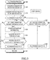
- the CPU 11 of the pre-collision control ECU 10 executes a routine represented by a flowchart shown in FIG. 5 , every time a predetermined time period elapses.
- the routine shown in FIG. 5 is a routine for determining whether or not the allowance condition is satisfied when the allowance condition has not been satisfied yet, and for determining whether or not an allowance cancel condition is satisfied when the allowance condition has been satisfied.
- Step 500 the CPU 11 starts the process from Step 500 shown in FIG. 5 , and proceeds to Step 505 to acquire the current accelerator operation amount AP from the accelerator opening sensor 21. Thereafter, the CPU 11 proceeds to Step 510 to acquire the vehicle velocity Vs based on the wheel pulse signals transmitted from the wheel velocity sensors 23, and proceeds to Step 515.
- the CPU 11 determines whether or not the allowance flag PF has been set to "0". It should be noted that the allowance flag PF has been set to "0" through an initial routine which is executed when the driver performs an operation to change a position of an ignition key switch (now shown) of the own vehicle SV from an off-position to an on-position.
- the CPU makes a "Yes” determination at Step 515 to proceed to Step 520.
- the CPU 11 determines whether or not the accelerator operation amount AP acquired at Step 505 is equal to or greater than the first operation amount threshold AP1th.
- the first operation amount threshold AP1th has been set at "90%".
- the CPU 11 makes a "No" determination at Step 520, and proceeds to Step 595 to tentatively terminate the present routine. As a result, the allowance condition is not satisfied so that the allowance flag PF does not change from "0".
- the CPU 11 makes a "Yes" determination at Step 520, and executes the following Step 525 through Step 535 in order.
- Step 525 The CPU 11 acquires the destination information 25 from the body ECU 24.
- Step 530 The CPU 11 acquires, from the velocity threshold table 14, the velocity threshold Vsth corresponding to the destination which is represented/indicated by the destination information 25 acquired at Step 525.
- Step 535 The CPU 11 determines whether or not the vehicle velocity Vs acquired at Step 510 is equal to or lower than the velocity threshold Vsth acquired at Step 530.
- the CPU 11 makes a "No" determination at Step 535 (that is, the CPU 11 determines that the allowance condition has not been satisfied), and proceeds to Step 595 to tentatively terminate the present routine. As a result, the allowance condition is not satisfied so that the allowance flag PF does not change from "0".
- the CPU 11 makes a "Yes” determination (that is, the CPU 11 determines that the allowance condition is satisfied), and proceeds to Step 540.
- the CPU 11 sets the allowance flag PF to "1", and proceeds to Step 595 to tentatively terminate the present routine.
- the allowance flag PF changes from "0" to "1".
- Step 515 the PCU 11 determines whether or not the accelerator operation amount AP acquired at Step 505 becomes smaller than the second operation amount threshold AP2th.
- the second operation amount threshold AP2th has been set at a value (i.e., "70%" in this example) smaller than the first operation amount threshold AP1th.
- the CPU 11 makes a "No" determination at Step 545, and proceeds to Step 595 to tentatively terminate the present routine. As a result, the allowance cancel condition is not satisfied so that the allowance flag does not change from "1".
- Step 545 when the accelerator operation amount AP becomes smaller than the second operation amount threshold AP2th, the CPU 11 makes a "Yes" determination at Step 545, and proceeds to Step 550.
- Step 550 the CPU 11 determines that the allowance condition is satisfied to set the allowance flag to "0", and proceeds to Step 595 to tentatively terminate the present routine. As a result, the allowance flag changes from "0" to "1".
- the first device when the accelerator operation amount AP is equal to or greater than the first operation amount threshold AP1th and the vehicle velocity Vs is equal to or lower than the velocity threshold Vsth corresponding to the destination, it is determined that the allowance condition is satisfied so that the allowance flag PF is set to "1".
- the allowance flag PF has been set to "1"
- the first device is allowed/permitted to perform the respective pre-collision controls when the accelerator operation amount AP is equal to or greater than the control threshold APcth. Therefore, the first device can improve/increase the possibility that the respective pre-collision controls are performed certainly when the wrong operation is performed.
- the first device When the accelerator operation amount AP becomes smaller than the second operation amount threshold AP2th after the allowance condition was satisfied once (that is, after the allowance flag PF was set to "1"), it is determined that the allowance cancel condition is satisfied so that the allowance flag is set to "0".
- the allowance flag PF has been set to "0"
- the first device is prohibited from performing the respective pre-collision controls when the accelerator operation amount AP is equal to or greater than the control threshold APcth. Therefore, the first device can prevent itself from performing the unnecessary pre-collision controls when the driver no longer performs the wrong operation after the driver once performed the wrong operation.
- the velocity threshold Vsth corresponding to the destination D has been set at "0km/h" in the velocity threshold table 14 shown in FIG. 3 .
- the allowance condition is satisfied in the destination D.
- the vehicle velocity Vs is equal to or lower than the "0km/h” at a time point at which the accelerator operation amount AP becomes equal to or greater than the first operation amount threshold AP1th, because the own vehicle SV inevitably accelerates until the accelerator operation amount AP becomes equal to or greater than the first operation amount threshold AP1th. Therefore, when the velocity threshold Vsth is "0km/h" (i.e., in the destination D), the pre-collision controls performed when the accelerator operation amount AP is equal to or greater than the control threshold APcth is substantially prohibited.
- the velocity threshold Vsth corresponding to the first specific destination has been set at a value greater/higher than "0km/h" in the velocity threshold table 14.
- the velocity threshold Vsth corresponding to the second specific destination has been set at "0km/h" in the velocity threshold table 14.
- the velocity threshold table 14 can be expressed as a table which stores information which indicates whether or not the pre-collision controls are allowed to be performed (or the pre-collision controls are prohibited) for each of the destinations.
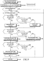
- the CPU 11 of the pre-collision control ECU 10 executes a routine represented by a flowchart shown in FIG. 6 , every time a predetermined time period elapses.
- the routine shown in FIG. 6 is a routine for determining whether or not the respective pre-collision controls are performed.
- Step 600 the CPU 11 starts the process from Step 600 shown in FIG. 6 to execute the following processes from Step 602 through Step 612 in order, and proceeds to Step 614.
- Step 602 The CPU 11 acquires the current accelerator operation amount AP from the accelerator opening sensor 21.
- Step 604 The CPU 11 acquires the object information from the millimeter wave radar 20.
- Step 606 The CPU 11 acquires the vehicle velocity Vs of the own vehicle SV based on the wheel pulse signals transmitted from the wheel velocity sensors 23.
- Step 608 The CPU 11 acquires the yaw rate Yr which is generated in the own vehicle SV from the yaw rate sensor 22.
- Step 610 The CPU 11 calculates a predicted traveling path RCR (refer to FIG. 2 ) of the own vehicle SV.
- Step 610 A process of Step 610 will be described in detail.
- the CPU 11 calculates a turning radius of the own vehicle SV based on the velocity Vs of the own vehicle SV acquired at Step 606 and the yaw rate acquired at Step 608. Thereafter, the CPU 11 predicts/extrapolates, as the predicted traveling path RCR, a traveling path along which a center point in the width direction of the own vehicle SV (the center point PO (referring to FIG. 2 ) of a wheel axis connecting a left wheel and a right wheel) will move.
- the CPU 11 predicts/extrapolates a path having an arc shape as the predicted traveling path RCR.
- the magnitude of the yaw rate is equal to "0"
- the CPU 11 predicts a straight path along a direction of acceleration of the own vehicle SV as the predicted traveling path RCR.
- Step 612 The CPU 11 extracts, as the obstacle(s), the object(s) which has (have) the probability of colliding with the own vehicle SV from among the object(s) represented by the object information, based on the location/position and the velocity of the object point(s) and the predicted traveling path RCR of the own vehicle SV.
- the selected obstacle(s) may include an object(s) which is (are) predicted not to collide with the own vehicle SV but to have a narrow margin of clearance between the object(s) and the own vehicle SV (or to extremely approach the own vehicle SV).
- Step 612 The process of Step 612 will next be described in detail with reference to FIG. 2 .
- the CPU 11 predicts/extrapolates, based on the "predicted traveling path RCR having a finite length", a predicted left traveling path LEC along which a "point PL away from a left end of a vehicle-body of the own vehicle SV in the left direction by a predetermined distance aL" will move, and a predicted right traveling path REC along which a "point PR away from a right end of the vehicle-body of the own vehicle SV in the right direction by a predetermined distance aR" will move.
- the predicted left traveling path LEC is a path obtained by parallelly shifting the predicted traveling path RCR in the left direction of the own vehicle SV by a "distance obtained by adding a half (W/2) of the vehicle-body width W to the predetermined distance aL".
- the predicted right traveling path REC is a path obtained by parallelly shifting the predicted traveling path RCR to the right direction of the own vehicle SV by a "distance obtained by adding a half (W/2) of the vehicle-body width W to the predetermined distance aR".
- Each of the distance aL and the distance aR is a distance which is longer than or equal to "0".
- the distance aL and the distance aR may be the same as each other, or may be different from each other.
- the CPU 11 specifies/designates, as a predicted traveling path area ECA, an area between the predicted left traveling path LEC and the predicted right traveling path REC.
- the CPU 11 calculates/predicts a moving trajectory of each of the objects based on the locations of each of the past objects with which the present object point is associated. Thereafter, the CPU 11 calculates/predicts a moving direction of each of the objects in relation to the own vehicle SV based on the calculated moving trajectory of each of the objects.
- the CPU 11 selects/extracts, as one or more of the obstacles which have high probability of colliding with the own vehicle SV,
- the CPU 11 predicts the "trajectory/path along which the point PL will move” as the predicted left traveling path LEC and the "trajectory/path along which the point PR will move” as the predicted right traveling path REC. Therefore, if both the values aL and aR are positive values, "the object which has been in the predicted traveling path area ECA and will intersect with the front end area TA of the own vehicle SV" may include an object which is likely to pass near the left side or the right side of the own vehicle SV, and the "object which will be in the predicted traveling path area ECA and will intersect with the front end area TA of the own vehicle SV” may include an object which is likely to pass near the left side or the right side of the own vehicle SV. Accordingly, the CPU 11 can select/extract, as the obstacle, the object which has a probability of passing near the left side or the right side of the own vehicle SV.
- Step 614 determines whether or not a final pre-collision brake flag ABF described later has been set at "0".
- the final pre-collision brake flag ABF is set to "1" at a time point at which the final pre-collision brake control is started.
- the final pre-collision brake flag ABF is set to "0" at a time point at which a predetermined time period elapses from a time point at which the own vehicle SV stops. It should be noted that the final pre-collision brake flag ABF is set to "0" through the above described initial routine.
- the CPU 11 makes a "Yes” determination at Step 614, and proceeds to Step 616 to determine whether or not any of the obstacle(s) has been extracted/selected at Step 612.
- the CPU 11 makes a "No" determination at Step 616, and proceeds to Step 695 to tentatively terminates the present routine. As a result, the pre-collision controls are not performed.
- the CPU 11 makes a "Yes" determination at Step 616, and proceeds to Step 618 to calculate the predicted collision time period TTC (Time to Collision) which it takes for each of the obstacles to reach the area TA of the own vehicle SV.
- TTC Time to Collision
- the CPU 11 obtains the predicted collision time period TTC of the obstacle by dividing the distance (the relative length) between the own vehicle SV and the obstacle point by the relative velocity of the obstacle in relation to the own vehicle SV.
- the predicted collision time period TTC is either one of a time period T1 or a time period T2, described below.
- the time period T1 is a time (period) which it takes for the obstacle to collide with the own vehicle SV (a time period from the present time point to a predicted collision time point).
- the time period T2 is a time (period) which it takes for the obstacle which has the high probability of passing near either side of the own vehicle SV to reach the closest point to the own vehicle SV (a time period from the present time point to the time point at which the own vehicle SV most closely approaches to the obstacle).
- the predicted collision time period TTC is a time which it takes for the obstacle to reach the "front end area TA of the own vehicle SV" under an assumption that the obstacle and the own vehicle SV move with keeping the relative velocity and the relative moving direction at the present time period.
- the predicted collision time period TTC represents a time period for which the first device is able to perform the respective pre-collision controls for preventing the own vehicle SV from colliding with the obstacle or a time period for which the driver is able to perform a collision preventing operation for preventing the own vehicle SV from colliding with the obstacle.
- the time to collision TTC is an index value (a collision index value) correlating with a probability (a collision probability) of a collision between the obstacle and the own vehicle SV.
- a collision probability a collision probability of a collision between the obstacle and the own vehicle SV.
- the predicted collision time period TTC is shorter, the collision probability is higher.
- the predicted collision time period TTC is longer, the collision probability is lower. It should be noted that, when a plurality of the obstacles have been extracted/selected at Step 612, the CPU select the shortest (minimum) predicted collision time period TTC among a plurality of the predicted collision time periods at Step 618.
- Step 620 determines whether or not the accelerator operation amount AP acquired at Step 602 is equal to greater than the control threshold APcth.
- the control threshold APcth has been set to "90%".
- the CPU 11 makes a "Yes" determination at Step 620, and proceeds to Step 622.
- the CPU 11 determines whether or not the above described allowance flag PF has been set to "1". When the allowance flag PF has been set to "0", the CPU 11 makes a "No" determination at Step 622, and proceeds to Step 695 to tentatively terminate the present routine.
- the situation where the CPU 11 makes a "No" determination at Step 622 means the situation where the accelerator operation amount AP at the present time point is equal to or greater than the control threshold APcth and the allowance condition has not been satisfied yet.
- An example of such a situation may be a situation where the driver presses/steps the accelerator pedal greatly when the vehicle velocity Vs is higher than the velocity threshold Vsth so that the accelerator operation amount AP becomes equal to or greater than the control threshold APcth.
- the driver is likely to perform the intentional operation for making the own vehicle SV overtake the preceding vehicle. Therefore, even if the predicted collision time period TTC is equal to or shorter than the time thresholds T(n)th, the CPU 11 does not perform the respective pre-collision controls. Therefore, in this situation, the CPU 11 tentatively terminates the present routine without executing processes for performing the pre-collision controls (Step 624 through Step 636). As a result, any one of the pre-collision controls is not performed.
- Step 624 the CPU 11 determines whether or not the predicted collision time period TTC calculated at Step 624 is equal to or shorter than the time threshold T1th for the alert control.
- the CPU 11 makes a "No" determination at Step 624, and proceeds to Step 695 to tentatively terminate the present routine. In this case, none of the pre-collision controls is performed, because the predicted time period TTC is longer than the time threshold T1th which is the longest among the time thresholds T(n)th.
- the CPU 11 makes a "Yes" determination at Step 624, and proceeds to Step 626 to determine whether or not the predicted time period TTC is equal to shorter than the time threshold T2th for the advanced pre-collision brake control.
- the CPU 11 makes a "No" determination at Step 626, and proceeds to Step 628.
- the CPU 11 performs the above described alert control (alert), and proceeds to Step 695 to tentatively terminate the present routine. More specifically, the CPU 11 transmits the display instruction information to the display unit 30 at Step 628 so as to display the above described alert screen on the display unit 30. In addition, the CPU 11 transmits the output instruction information to the speaker 31 so as to output/generate the above described alert sound from the speaker 31.
- the CPU 11 stops/cancels performing the alert control when at least one of the following conditions (1A) through (3A) is satisfied owing to the collision preventing operation by the driver, a moving state change of the obstacle, and the like.
- the CPU 11 makes a "Yes" determination at Step 626, and proceeds to Step 630 to determine whether or not the predicted collision time period TTC is equal to or shorter than the time threshold T3th for the final pre-collision brake control.
- the CPU 11 makes a "No" determination at Step 630, and proceeds to Step 632.
- the CPU 11 performs the above described advanced pre-collision brake control, and proceeds to Step 695 to tentatively terminate the present routine. More specifically, when the shortest (minimum) predicted collision time period TTC is equal to or shorter than the time threshold T2th and longer than a time threshold T2th' (refer to FIG.
- the CPU 11 calculates a target deceleration TG1 based on the distance between the own vehicle SV and the object having the shortest TTC, and the relative velocity of the object having the shortest TTC in relation to the own vehicle SV at this time point.
- the target deceleration TG1 is calculated so as to be a deceleration necessary for the own vehicle SV to stop before the own vehicle SV collides with the obstacle which was extracted at Step 612 and has the shortest TTC.
- the CPU 11 transmits the brake instruction signal for decelerating the own vehicle SV at the target deceleration TG1 to the brake ECU 32, and transmits the torque decreasing instruction signal to the engine ECU 36.
- the CPU 11 calculates a target deceleration TG2 based on the distance between the own vehicle SV and the object having the shortest TTC, and the relative velocity of the object having the shortest TTC in relation to the own vehicle SV at this time point.
- the target deceleration TG2 is calculated so as to be greater than the target deceleration TG1 and a deceleration necessary for the own vehicle SV to stop before the own vehicle SV collides with the obstacle which was extracted at Step 612 and has the shortest TTC.
- the target deceleration TG2 is calculated so as to be greater than the target deceleration TG1 and a maximum deceleration which is able to be generated by the own vehicle SV.
- the CPU 11 transmits the brake instruction signal for decelerating the own vehicle SV at the target deceleration TG2 to the brake ECU 32, and transmits the torque decreasing instruction signal to the engine ECU 36.
- the own vehicle SV is decelerated more rapidly at the target deceleration TG2 than at the target deceleration TG1. It should be noted that the CPU 11 continues performing the alert control while the CPU 11 is performing the advanced pre-collision brake control.
- the CPU 11 stops/cancels performing the advanced pre-collision brake control when at least one of the following conditions (1B) through (3B) is satisfied owing to the collision preventing operation by the driver, a moving state change of the obstacle, and the like.
- the CPU 11 makes a "Yes" determination at Step 630, and proceeds to Step 634.
- the CPU 11 sets the final pre-collision brake flag ABF to "1", and proceeds to Step 636.
- the CPU 11 performs the final pre-collision brake control, and proceeds to Step 695 to tentatively terminate the present routine. More specifically, the CPU 11 transmits the brake instruction signal for decelerating the own vehicle SV at the target deceleration TG2 to the brake ECU 32 and the torque decreasing instruction signal to the engine ECU 36. It should be noted that the CPU 11 continues performing the alert control while the CPU 11 is performing the final pre-collision brake control.
- the final pre-collision brake control is different from the advanced pre-collision brake control in that once the CPU 11 starts the final pre-collision brake control, the CPU 11 continues braking the own vehicle SV at the target deceleration TG2 until the vehicle velocity Vs becomes "0" (the own vehicle SV stops) regardless of a presence/absence of the obstacle and the predicted collision time period TTC.
- the vehicle velocity Vs becomes "0" through the final pre-collision brake control at time point te in FIG. 4 .
- the CPU 11 has set the target deceleration to the target deceleration TG1 in order to maintain the vehicle velocity Vs at "0" during a time period from "the time point (the time point te) at which the own vehicle SV stops” to a time point at which a predetermined time period elapses from the time point te in the final pre-collision brake control.
- the own vehicle SV is not decelerated at the target deceleration TG1 because the own vehicle SV stops. Therefore, the brake ECU 32 determines that the braking force is insufficient so that the brake ECU 32 continues driving the braking actuator 34.
- the CPU 11 determines whether or not a stop maintenance flag SKF has been set to "0".
- the stop maintenance flag SKF is set to "1" at a time point at which the vehicle velocity Vs becomes “0" while the CPU 11 is performing the final pre-collision brake control.
- the stop maintenance flag SKF is set to "0" at the time point at which the predetermined time period elapses from the time point at which the vehicle velocity Vs becomes "0" owing to the final pre-collision brake control.
- the stop maintenance flag SKF is set to "0" through the initial routine.
- Step 638 the CPU 11 makes a "Yes” determination at Step 638, and proceeds to Step 640 to determine whether or not the vehicle velocity Vs acquired at Step 606 is "0".
- Step 640 the CPU 11 makes a "No" determination at Step 640, and proceeds to Step 636 to perform the final pre-collision brake control so as to decelerate the own vehicle SV. Thereafter, the CPU 11 proceeds to Step 695 to tentatively terminate the present routine.
- Step 642 the CPU 11 sets the stop maintenance flag SKF to "1", and proceeds to Step 644.
- Step 644 the CPU 11 sets a stop maintenance timer SKT to "0" so as to initialize the stop maintenance timer SKT, and proceeds to Step 646.
- the stop maintenance timer SKT is used for determining whether or not the predetermined time period elapses from the time point at which the vehicle velocity Vs becomes "0" owing to the final pre-collision brake control.
- the CPU 11 determines whether or not the stop maintenance timer SKT is equal to or smaller than a timer threshold Tsth.
- the CPU 11 makes a "Yes" determination at Step 646, and proceeds to Step 648.
- the CPU 11 performs a stop maintenance control for maintaining a stop state of the own vehicle SV (in other words, maintaining the vehicle velocity Vs at "0") as a part of the final pre-collision brake control.
- Step 648 the CPU 11 transmits the brake instruction signal for decelerating the own vehicle SV at the target deceleration TG1 to the brake ECU 32, and transmits the torque decreasing instruction signal to the engine ECU 36. Thereafter, the CPU 11 proceeds to Step 695 to tentatively terminate the present routine.
- Step 638 the CPU 11 again started to execute after the stop maintenance flag SKF was set to "1" at Step 642
- the CPU 11 makes a "No" determination at Step 638, and proceeds to Step 650.
- Step 650 the CPU 11 sets the stop maintenance timer SKT to a value obtained by adding "1" to the current stop maintenance timer SKT, and proceeds to Step 646.
- the CPU 11 adds "1" to the stop maintenance timer SKT every time the process of Step 650 is executed, and continues performing the stop maintenance control at Step 648 during a time period from a time point at which the CPU 11 sets the stop maintenance flag to "1" at Step 642 to a time point at which the CPU 11 makes a "No" determination at Step 646 (that is, during a time period from a time point at which the vehicle velocity Vs becomes "0" owing to the final pre-collision brake control to a time point at which the predetermined time period elapses from the time point at which the vehicle velocity Vs becomes "0").
- Step 646 the CPU 11 makes a "No" determination at Step 646, and proceeds to Step 652.
- Step 652 the CPU 11 sets the stop maintenance flag SKF to "0", and proceeds to Step 654 to set the final pre-collision brake flag ABF to "0". Thereafter, the CPU 11 proceeds to Step 695 to tentatively terminate the present routine.
- the final pre-collision brake flag ABF is set to "1" and the final pre-collision brake control is started. Once the final pre-collision brake control is started, the final pre-collision brake flag ABF is not set to "0" until the predetermined time period elapses from the time point at which the vehicle velocity Vs becomes "0". When the final pre-collision brake flag ABF has been set to "1", the CPU 11 makes a "No" determination at Step 614. As a result, the CPU 11 does not execute the process of Step 616 through Step 634.
- the own vehicle SV is decelerated until the vehicle velocity Vs becomes "0" regardless of the predicted collision time period TTC.
- the stop state of the own vehicle SV is maintained until the predetermined time period elapses from the time point at which the vehicle velocity Vs becomes "0".
- the CPU 11 does not use the predicted collision time period TTC while the CPU 11 is performing the final pre-collision brake control, because "the millimeter wave radar detection error in detecting "the location and the relative velocity" of the object which is present in a short distance area from the millimeter wave radar 20" tends to be great.
- the CPU 11 makes a "No" determination at Step 620. Thereafter, the CPU 11 proceeds the processes after Step 624 without executing the process of Step 622.
- the CPU 11 performs the respective pre-collision controls when the predicted collision time period TTC is equal to or shorter than the time thresholds T(n)th, and the CPU 11 does not perform the respective pre-collision controls when the predicted collision time period TTC is longer than the time threshold T1th (which is the longest threshold among the time thresholds T(n)).
- the CPU 11 sets the allowance flag to "1" at Step 540 shown in FIG. 5 .
- the CPU 11 makes a "Yes" determination at Step 622 shown in FIG. 6 .
- the CPU 11 performs the respective pre-collision controls. Therefore, the first device can improve/increase the possibility that the respective pre-collision controls are performed certainly when the collision probability becomes high due to the wrong operation which is performed on the accelerator.
- the allowance condition is not satisfied. Therefore, the allowance flag continues being "0".
- the CPU 11 makes a "No" determination at Step 622 shown in FIG. 6 . In this case, the CPU 11 does not perform any of the pre-collision controls, and tentatively terminates the routine shown in FIG. 6 .
- the first device determines that the driver is performing the intentional operation, when the driver presses/steps the accelerator pedal greatly (that is, when the accelerator operation amount AP is equal to or greater than the control threshold APcth) while the driver is not performing the wrong operation on the accelerator pedal and the collision probability becomes high.
- the first device does not perform any of the pre-collision controls. Accordingly, the first device can reduce/decrease the possibility that the unnecessary pre-collision controls are performed while the driver is performing the intentional operation.
- both the destination information 25 and the velocity threshold table 14 have been stored in the first device.
- the destination information 25 represents (or is indicative of) the destination (place of destination) of the own vehicle SV.
- the velocity threshold table 14 includes/stores the information on the velocity threshold Vsth corresponding to each of the destinations.
- the destination information 25 is acquired at Step 525 shown in FIG. 5
- the velocity threshold Vsth corresponding to the destination represented by the acquire destination information 25 is acquired at Step 530.
- the CPU 11 determines whether or not the vehicle velocity Vs at the present time point is equal to or lower than the velocity threshold Vsth acquired at Step 530.
- the velocity threshold Vsth corresponding to the low velocity overtaking region region has been set to the relatively low value (refer to the destination C), and the velocity threshold Vsth corresponding to the high velocity wrong operation region has been set to the relatively high value (refer to the destination A). Therefore, when the own vehicle SV travels in the low velocity overtaking region, the possibility that the allowance condition is satisfied can be reduced/decreased even if the own vehicle SV starts overtaking the preceding vehicle when the vehicle velocity Vs is relatively low, so that the possibility that the unnecessary pre-collision controls are performed can be reduce/decreased.
- a driving support device (hereinafter, referred to as a "second device") according to a second embodiment of the present disclosure will be next described.
- the second device is different from the first device only in that the a velocity threshold table 70 shown in FIG. 7 in place of the velocity threshold table 14 shown in FIG. 3 has been stored in the ROM 12 included in the pre-collision control ECU 10.
- This velocity threshold table 70 is a table for defining the velocity threshold Vsth for each pre-collision control (that is, for each of the alert control, the advanced pre-collision brake control, and the final pre-collision brake control) corresponding to each of the destinations.
- the velocity threshold table 14 of the first device defines the same velocity thresholds Vsth for all of the pre-collision controls as each other.
- a single value is commonly set to be used as the velocity threshold Vsth for all of the pre-collision controls for each of the destinations.
- the velocity threshold table 70 can define the velocity threshold Vsth for each of the pre-collision controls independently from each other.
- an independent single value is set to be used as the velocity threshold Vsth for each of the pre-collision controls for each of the destinations. Therefore, the allowance condition for the alert control, the allowance condition for the advanced pre-collision brake control, and the allowance condition for the final pre-collision brake control can be set independently from each other.
- the CPU 11 of the pre-collision control ECU 10 executes "a routine for executing an allowance process" represented by a flowchart shown in FIG. 8 , every time a predetermined time period elapses. It should be noted that (values of) "an allowance flag PFA for the alert control, an allowance flag PFB for the advanced pre-collision brake control, and an allowance flag PFC for the final pre-collision brake control” are changed through this routine. Furthermore, (the values of) these flags have been set to "0" through the above described initial routine.
- Step 800 the CPU 11 starts the process from Step 800, and executes the processes of Step 505, Step 510, and Step 525 in order. Subsequently, the CPU 11 proceeds to Step 805 to acquire, from the velocity threshold table 70, "the velocity threshold (Vs1th, Vs2th, and Vs3th) for each of the pre-collision controls" corresponding to the destination represented by the destination information 25 acquired at Step 525.
- Step 810 determines whether or not the flag PFA has been set to "0".
- the CPU 11 makes a "Yes” determination at Step 810, and proceeds to Step 815 to determine whether or not the allowance condition for the alert control is satisfied.
- the allowance condition for the alert control is satisfied when both of the following two conditions are satisfied.
- Step 815 When the allowance condition for the alert control is satisfied, the CPU 11 makes a "Yes" determination at Step 815, and proceeds to Step 820.
- Step 820 the CPU 11 sets the flag PFA to "1", and proceeds to Step 835.
- the CPU 11 makes a "No" determination at Step 815, and proceeds to Step 835 directly.
- Step 810 when the flag PFA has not been set to "0" at the time point at which the CPU 11 executes the process of Step 810, the CPU 11 makes a "No" determination at Step 810, and proceeds to Step 825 to determine whether or not the accelerator operation amount AP is smaller than the second operation amount threshold AP2th.
- the CPU 11 makes a "Yes" determination at Step 825, and proceeds to Step 830.
- the CPU 11 sets the flag PFA to "0", and proceeds to Step 835.
- the accelerator operation amount AP is equal to or greater than the second operation amount threshold AP2th, the CPU 11 makes a "No" determination at Step 825, and proceeds to Step 835 directly.
- Step 835 the CPU 11 determines whether or not the flag PFB has been set to "0". When the flag PFB has been set to "0", the CPU 11 makes a "Yes" determination at Step 835, and proceeds to Step 840 to determine whether or not the allowance condition for the advanced pre-collision brake control is satisfied.
- the allowance condition for the advanced pre-collision brake control is satisfied when both of the following two conditions are satisfied.
- Step 845 the CPU 11 sets the flag PFB to "1" to proceed to Step 860.
- the CPU 11 makes a "No" determination at Step 840, and proceeds to Step 860 directly.
- Step 835 determines whether or not the accelerator operation amount AP is smaller than the second operation amount threshold AP2th.
- the CPU 11 makes a "Yes" determination at Step 850, and proceeds to Step 855.
- Step 855 the CPU 11 sets the flag PFB to "0", and proceeds to Step 860.
- the accelerator operation amount AP is equal to or greater than the second operation amount threshold AP2th, the CPU 11 makes a "No" determination at Step 850, and proceeds to Step 860 directly.
- Step 860 the CPU 11 determines whether or not the flag PFC has been set to "0". When the flag PFC has been set to "0", the CPU 11 makes a "Yes" determination at Step 860, and proceeds to Step 865 to determine whether or not the allowance condition for the final pre-collision brake control is satisfied.
- the allowance condition for the final pre-collision brake control is satisfied when both of the following two conditions are satisfied.
- Step 865 When the allowance condition for the final pre-collision brake control is satisfied, the CPU 11 makes a "Yes" determination at Step 865, and proceeds to Step 870. At Step 870, the CPU 11 sets the flag PFC to "1" to proceed to Step 895. In contrast, when the allowance condition for the final pre-collision brake control is not satisfied, the CPU 11 makes a "No" determination at Step 865, and proceeds to Step 895 directly.
- Step 860 when the flag PFC has not been set to "0" at the time point at which the CPU 11 executes the process of Step 860, the CPU 11 makes a "No" determination at Step 860, and proceeds to Step 875 to determine whether or not the accelerator operation amount AP is smaller than the second operation amount threshold AP2th.
- the CPU 11 makes a "Yes" determination at Step 875, and proceeds to Step 880.
- Step 880 the CPU 11 sets the flag PFC to "0", and proceeds to Step 895.
- the accelerator operation amount AP is equal to or greater than the second operation amount threshold AP2th, the CPU 11 makes a "No" determination at Step 875, and proceeds to Step 895 directly.
- Step 895 the CPU 11 tentatively terminates the present routine.
- the CPU 11 executes a routine for performing a pre-collision control performing process represented by a flowchart shown in FIG. 9 , every time a predetermined time period elapses. It should be noted that the final pre-collision brake flag ABF is set to "0" through the above described initial routine.
- Step 900 the CPU 11 starts the process from Step 900, and executes the processes of Step 602 through Step 612 in order, so as to acquire the various types of the parameters. Subsequently, the CPU 11 proceeds to Step 614 to determine whether or not the final pre-collision brake flag ABF has been set to "0". When the final pre-collision brake flag ABF has not been set to "0", the CPU 11 makes a "No" determination at Step 614, and proceeds to Step 995 to tentatively terminate the present routine.
- the CPU 11 makes a "Yes” determination at Step 614, and proceeds to Step 616 to determine whether or not at least one obstacle has been extracted.
- the CPU 11 makes a "No" determination at Step 616, and proceeds to Step 995 to tentatively terminate the present routine.
- the CPU 11 makes a "Yes" determination at Step 616, and proceeds to Step 905 to determine whether or not a first performance condition for the alert control.
- the first performance condition for the alert control is satisfied when all of the following three conditions are satisfied.
- the predicted collision time period TTC is the shortest (minimum) TTC among the predicted collision time period(s) of the extracted obstacles. This point is applied to cases described later.
- Step 910 When the first performance condition is satisfied, the CPU 11 makes a "Yes" at Step 905, proceeds to Step 910 to perform the alert control, and proceeds to Step 925. In contrast, when the first performance condition is not satisfied, the CPU 11 makes a "No" at Step 905, and proceeds to Step 915 to determine whether or not a second performance condition for the alert control.
- the second performance condition for the alert control is satisfied when all of the following two conditions are satisfied.
- Step 915 the CPU 11 makes a "Yes" determination at Step 915, proceeds to Step 910 to perform the alert control, and proceeds to Step 925.
- Step 920 if the CPU 11 is performing the alert control, the CPU 11 stops/cancels the alert control, and proceeds to Step 925. If the CPU 11 is not performing the alert control, the CPU 11 executes no process at Step 920, and proceeds to Step 925.
- the CPU 11 determines whether or not a first performance condition for the advanced pre-collision brake control is satisfied.
- the first performance condition for the advanced pre-collision brake control is satisfied when all of the following three conditions are satisfied.
- the CPU 11 makes a "Yes" determination at Step 925, proceeds to Step 930 to perform the advanced pre-collision brake control, and proceeds to Step 945.
- the CPU 11 makes a "No" determination at Step 925, and proceeds to Step 935 to determine whether or not the second performance condition for the advanced pre-collision brake control is satisfied.
- the second performance condition for the advanced pre-collision brake control is satisfied when all of the following two conditions are satisfied.
- Step 935 When the second performance condition for the advanced pre-collision brake control is satisfied, the CPU 11 makes a "Yes" determination at Step 935, proceeds to Step 930 to perform the advanced pre-collision brake control, and proceeds to Step 945. In contrast, when the second performance condition for the advanced pre-collision brake control is not satisfied, the CPU 11 makes a "No" determination at Step 935 to proceed to Step 940.
- Step 940 if the CPU 11 is performing the advanced pre-collision brake control, the CPU 11 stops/cancels the advanced pre-collision brake control, and proceeds to Step 945. If the CPU 11 is not performing the advanced pre-collision brake control, the CPU 11 executes no process at Step 940, and proceeds to Step 945.
- the CPU 11 determines whether or not a first performance condition for the final pre-collision brake control is satisfied.
- the first performance condition for the final pre-collision brake control is satisfied when all of the following three conditions are satisfied.
- Step 945 the CPU 11 makes a "Yes" determination at Step 945, proceeds to Step 950 to perform the final pre-collision brake control.
- the CPU 11 continues performing the final pre-collision brake control until the vehicle velocity Vs becomes "0", and continues performing the final pre-collision brake control until the predetermined time period elapses from the time point at which the vehicle velocity becomes "0", in the same manner as the final pre-collision brake control performed by the first device. Subsequently, the CPU 11 proceeds to Step 955 to set the flag ABF to "1", and proceeds to Step 995 to tentatively terminate the present routine. It should be noted that the CPU 11 sets the flag ABF to "0" when the CPU 11 completes the final pre-collision brake control.
- the CPU 11 makes a "No" determination at Step 945, and proceeds to Step 960 to determine whether or not the second performance condition for the final pre-collision brake control is satisfied.
- the second performance condition for the final pre-collision brake control is satisfied when all of the following two conditions are satisfied.
- Step 960 When the second performance condition for the final pre-collision brake control is satisfied, the CPU 11 makes a "Yes" determination at Step 960, and executes the processes of Step 950 and Step 955 to proceed to Step 995. In contrast, when the second performance condition for the final pre-collision brake control is not satisfied, the CPU 11 makes a "No" determination at Step 960, and proceeds to Step 995 directly to tentatively terminate the present routine.
- the second device can set the independent allowance conditions (the condition for setting the flag PFA to "1", the condition for setting the flag PFB to "1", and the condition for setting the flag PFC to "1") for the pre-collision controls (the alert control, the advanced pre-collision brake control, and the final pre-collision brake control) which are performed when the accelerator operation amount AP is equal to or greater than the control threshold APcth.
- the second device can achieve the following effects.
- the own vehicle SV tends to complete overtaking the preceding vehicle before the predicted collision time period TTC becomes equal to or shorter than the time threshold T3th. If the velocity threshold Vs1th for the alert control and the velocity threshold Vs2th for the advanced pre-collision brake control have been set to the same value as the velocity threshold Vs3th for the final pre-collision brake control, the allowance conditions for the alert control, the advanced pre-collision brake control, and the final pre-collision brake control become satisfied simultaneously (at the same timing). Therefore, when the own vehicle SV overtakes the preceding vehicle, a "situation where both of the alert control and the advanced pre-collision brake control are performed, but the final pre-collision brake control is not performed" occurs. Such a situation annoys the driver.
- the second device can set both the velocity threshold Vs1th for the alert control and the velocity threshold Vs2th for the advanced pre-collision brake control to values smaller than the velocity threshold Vs3th for the final pre-collision brake control (for example, refer to the destination C of the table shown in FIG. 7 ).
- both the allowance condition for the alert control and the allowance condition for the advanced pre-collision brake control is harder to be satisfied than the allowance condition for the final pre-collision brake control. Therefore, even if the predicted collision time period TTC becomes equal to or shorter than the time threshold T1th while the own vehicle SV is overtaking the preceding vehicle, the second device hardly performs the alert control, because the allowance condition for the alert control has not been satisfied in many cases.
- the second hardly performs the advanced pre-collision brake control, because the allowance condition for the advanced pre-collision brake control has not been satisfied in many cases. That is, the second device can reduce/decrease a possibility that the unnecessary alert control and/or the unnecessary advance control are performed. In addition, the allowance condition for the final pre-collision brake control is satisfied more easily than the allowance condition for the alert control and the allowance condition for the advanced pre-collision brake control. Therefore, the second device can improve/increase the possibility that the final pre-collision brake control is performed when the driver performs the wrong operation.
- the velocity thresholds Vs1th and Vs2th corresponding to the destination C are set at "10km/h", and the velocity threshold Vs3th corresponding to the destination C is set at "15km/h”. It is assumed that the accelerator operation amount AP becomes equal to or greater than the operation amount threshold AP1th when the vehicle velocity Vs is "13km/h" while the driver is performing the operation for making the own vehicle SV overtake the preceding vehicle.
- the vehicle velocity Vs is higher than any of the velocity thresholds Vs1th and Vs2th, and the vehicle velocity Vs is lower than the velocity threshold Vs3th.
- the second device determines that neither the allowance condition for the alert control nor the allowance condition for the advanced pre-collision brake control is satisfied, and the allowance condition for the final pre-collision brake control is satisfied. Even when the predicted collision time period TTC becomes equal to or shorter than the time threshold T1th, the second device does not perform the alert control, since the allowance condition for the alert control has not been satisfied. In addition, even when the predicted collision time period TTC becomes equal to or shorter than the time threshold T2th, the second device does not perform the advanced pre-collision brake control, since the allowance condition for the advanced pre-collision brake control has not been satisfied. Moreover, the second device performs the final pre-collision brake control, if the own vehicle SV has not completed overtaking the preceding vehicle before the predicted collision time period TTC becomes equal to or shorter than the time threshold T3th.
- the accelerator operation amount AP becomes equal to or greater than the operation amount threshold AP1th when the vehicle velocity Vs is "13km/h" while the driver is performing the wrong operation.
- the second device determines that only the allowance condition for the final pre-collision brake control is satisfied. Therefore, even when the predicted collision time period TTC becomes equal to or shorter than the time threshold T1th, the second device does not perform the alert control. Similarly, even when the predicted collision time period TTC becomes equal to or shorter than the time threshold T2th, the second device does not perform the advanced pre-collision brake control. However, the second device performs the final pre-collision brake control, when the predicted collision time period TTC becomes equal to or shorter than the time threshold T3th.
- the velocity threshold Vsth corresponding to the destination C has been set at "10km/h" in the velocity threshold table 14 of the first device. Therefore, none of the allowance conditions is satisfied under any of the assumptions described above. Accordingly, the first device does not perform any pre-collision controls.
- each of the threshold velocity Vs1th for the alert control and the threshold velocity Vs2th for the advanced pre-collision brake control can be set to a value smaller than the velocity threshold Vs3th for the final pre-collision brake control, corresponding to the specific destination. Therefore, in the case where the own vehicle SV travels in the specific destination, the second device can reduce/decrease the possibility that the unnecessary alert control and the unnecessary advanced pre-collision brake control are performed when the own vehicle SV is overtaking the preceding vehicle, and can prevent "the possibility that at least the final pre-collision brake control is performed certainly" from being reduced/decreased, when the driver is performing the wrong operation.
- the final pre-collision brake control continues being performed until the time point at which the predetermined time period elapses from the time point at which the velocity vehicle Vs becomes "0".
- the alert control which is started when the accelerator operation amount AP is equal to or greater than the control threshold APcth is stopped/canceled when at least one of the above described conditions (1A) through (3A) is satisfied.
- the advanced pre-collision brake control which is started when the accelerator operation amount AP is equal to or greater than the control threshold APcth is stopped/canceled when at least one of the above described conditions (1B) through (3B) is satisfied.
- the velocity threshold Vs3th for the final pre-collision brake control can be set to a value smaller than the vehicle threshold Vs1th for the alert control or to a value smaller than the vehicle threshold Vs2th for the advanced pre-collision brake control (refer to the destination A of the table in FIG. 7 ). Therefore, according to the second device, the allowance condition for the final pre-collision brake control is designed to be harder to be satisfied than the allowance condition for the alert control and the allowance condition for the advanced pre-collision brake control. As a result, the possibility that the final pre-collision brake control is performed can be reduced/decreased.
- the second device can prevent the "possibility that the alert control and the advanced pre-collision brake control are performed when the wrong operation is performed" from being reduced/decreased.
- the velocity thresholds Vs1th and Vs2th have been set to "20km/h", and the velocity threshold Vs3th has been set to "10km/h” corresponding to the destination A according to the velocity threshold table 70 shown in FIG. 7 .
- the accelerator operation amount AP becomes equal to or greater than the operation amount threshold AP1th when the vehicle velocity Vs is "13km/h" while the driver is performing the operation for making the own vehicle SV overtake the preceding vehicle.
- the vehicle velocity Vs is equal to or lower than any of the velocity thresholds Vs1th and Vs2th, and the vehicle velocity Vs is higher than the velocity threshold Vs3th.
- the second device determines that the allowance conditions for the alert control and the advanced pre-collision brake control are satisfied, and the allowance condition for the final pre-collision brake control is not satisfied. Accordingly, the second device performs the alert control when the predicted collision time period TTC becomes equal to or shorter than the time threshold T1th, because the allowance condition for the alert control has been satisfied. Furthermore, the second device performs the advanced pre-collision brake control when the predicted collision time period TTC becomes equal to or shorter than the time threshold T2th, because the allowance condition for the advanced pre-collision brake control has been satisfied. However, the allowance condition for the final pre-collision brake control has not been satisfied, and thus, the second device does not perform the final pre-collision brake control even when the predicted collision time period TTC becomes equal to or shorter than the time threshold T3th.
- the vehicle threshold Vsth for the respective pre-collision controls which is designed not to be performed has been set at "0km/h” in the velocity threshold table 70. More specifically, "the velocity threshold Vs1th for the alert control and the velocity threshold Vs2th for the advanced pre-collision brake control" corresponding to the destination D have been set at "0km/h” in the velocity threshold table 70. For this reason, as with the velocity threshold table 14, the velocity threshold table 70 can be expressed as a table which stores information which indicates whether or not the respective pre-collision controls are allowed to be performed (or the respective pre-collision controls are prohibited) for each of the destinations.
- the second device can set the velocity threshold Vsth for each of the pre-collision controls. Therefore, the allowance condition for each of the pre-collision controls which is desired to be performed can be made to be satisfied easily, and the allowance condition for each of the pre-collision controls which is desired to be performed can be made to be harder to be satisfied.
- the CPU 11 acquires the present location of the own vehicle SV from the GPS receiver 26, and regards/specifies a "region including/covering the acquired present location" as the destination (destination information). According to this embodiment, the CPU 11 can accurately acquire the velocity threshold corresponding to the region including the present location of the own vehicle SV.
- "prohibition information indicating that a certain pre-collision control is prohibited” is stored in the memory area where the "0km/h" as the velocity threshold Vsth is stored in the velocity threshold table 14 or 70.
- the CPU 11 acquires "the information indicative of the velocity threshold Vsth or the prohibition information" corresponding to "the destination represented by the destination information 25" from the velocity threshold 14 at Step 530 in the routine shown in FIG. 5 .
- the CPU 11 proceeds to Step 535 to determine whether or not the vehicle velocity Vs is equal to or lower than the vehicle velocity Vsth.
- the CPU 11 proceeds to Step 540 to set the allowance flag to "1".
- Step 535 when the vehicle velocity Vs is higher than the velocity threshold Vsth, the CPU 11 makes a "No" determination at Step 535, and proceeds to Step 595 to tentatively terminate the present routine.
- the CPU 11 determines that the allowance condition is not satisfied to proceed to Step 550 from Step 530 so as to set the allowance flag to "0". Thereafter, the CPU 11 proceeds to Step 595 to tentatively terminate the present routine.
- the CPU 11 makes a "No" determination at Step 622 in the routine shown in FIG. 6 . As a result, any of the pre-collision controls are not performed.
- the accelerator operation amount AP is detected by the accelerator opening sensor 21.
- the accelerator operation amount AP is detected by a throttle opening sensor (not shown).
- the throttle opening sensor detects opening of the throttle valve of the internal combustion engine. As the accelerator operation amount AP becomes greater, the throttle valve opening becomes greater.
- the CPU 11 determines whether or not the accelerator operation amount AP is equal to or greater than the first operation amount AP1th and an operation speed indicative of a speed of the operation performed on the accelerator pedal is equal to or higher than an operation speed threshold. In this embodiment, when the accelerator operation amount AP is equal to or greater than the first operation amount AP1th and the operation speed is equal to or higher than the operation speed threshold, the CPU 11 makes a "Yes" determination at Step 520 to proceed to Step 525.
- the CPU 11 makes a "No" determination at Step 520 to proceed to Step 595 so as to tentatively terminate the present routine.
- the CPU 11 determines whether or not a current TTC is longer than a previous TTC.
- the current TTC is the shortest/minimum predicted collision time period TTC among the predicted collision time periods TTC which were calculated at Step 618 in the routine shown in FIG. 6 when the routine was executed at a time point (a latest time point) which is the latest to the current time point.
- the previous TTC is the minimum predicted collision time period TTC among the predicted collision time periods TTC which were calculated at Step 618 in the routine when the routine was executed at a time point one time before the latest time point (a time point which is the predetermined time period before the latest time point).
- the CPU 11 when the current TTC is longer than the previous TTC, the CPU 11 makes a "Yes" determination at Step 545, and proceeds to Step 550 to set the allowance flag PF to "0".
- the CPU 11 makes a "No" determination at Step 545, and proceeds to Step 595 to tentatively terminate the routine shown in FIG. 5 . This is because, when the drivers performs the steering operation so as to prevent the own vehicle SV from colliding with the obstacle, the current TTC of the obstacle becomes longer than the previous TTC of the obstacle, and thus, the CPU 11 can determine that the allowance cancel condition is satisfied so as to set the allowance flag PF to "0".
- the CPU 11 may set the allowance flag to "0" when the current TTC is equal to or longer than the present TTC, only in a case where the accelerator operation amount AP is equal to or greater than the second operation amount threshold AP2th (only in the case where the CPU 11 makes a "No" determination at Step 545 shown in FIG. 5 ).
- the CPU 11 when the current TTC is longer than the previous TTC, and a magnitude of a subtraction value (a difference) between the current TTC and the previous TTC is equal to or larger than a predetermined value, the CPU 11 makes a "Yes" determination at Step 545 to set the allowance flag to "0".
- the CPU 11 uses the target deceleration TG as the collision index value correlating with the collision probability instead of the predicted collision time period TTC.
- the CPU 11 calculates, as the target deceleration TG, a deceleration at which the own vehicle SV can stop before the own vehicle SV reaches each of the obstacles, based on the relative velocity of each of the obstacles and the distance between each of the obstacles and the own vehicle SV.
- the target deceleration TG is a negative value. Therefore, as the target deceleration TG which is the negative value is smaller, the collision probability is higher.
- the collision index value is smaller, regardless of whether the predicted collision time period TTC or the target deceleration TG is used as the collision index value.
- the collision index value may be a value which enables the driving support device to determine the collision probability.
- the relative velocity of the obstacle in relation to the own vehicle SV, the relative distance of the obstacle in relation to the own vehicle, a relative lateral velocity of the obstacle in relation to the own vehicle SV, or the like is used as the collision index value.
- control threshold APcth is a valued different from a value set as the first operation amount threshold AP1th. In some embodiments, the control threshold APcth has been set to a value equal to or greater than the second operation amount threshold AP2th.
- the CPU 11 executes "the process for the alert control at Step 628" immediately after the CPU 11 makes a "Yes" determination at Step 624, and then, proceeds to Step 626.
- the alert control continues being performed while the advanced pre-collision brake control or the final pre-collision brake control is being performed.
- the pre-collision controls are performed only when the vehicle velocity Vs is within a predetermined range.
- the accelerator pedal is described as an example of the accelerator on which the driver performs the operation in order to accelerate the own vehicle SV, the accelerator is not limited to this example (the accelerator pedal).
- an accelerator lever is used as the accelerator.
- the CPU 11 calculates the turning radius of the own vehicle SV based on the vehicle velocity Vs of the own vehicle SV and "a steering angel ⁇ of a steering wheel which are detected by a steering angle sensor (not shown)", to calculate the predicted traveling path RCR at Step 610 in the routine shown in FIG. 6 .
- the CPU 11 calculates/updates the target deceleration TG for the advanced pre-collision brake control based on "the distance between the obstacle and the own vehicle SV" and "the relative velocity of the obstacle in relation to the own vehicle SV" at a time point at which the CPU 11 executes the process of Step 632 shown in FIG. 6 , every time the CPU executes the process of Step 632 while the predicted collision time period TTC is equal to or shorter than the time threshold T2th.
- the target deceleration TG2 for the final pre-collision brake control is set to the target deceleration TG for the advanced pre-collision brake control which is lastly calculated in the advanced pre-collision brake control before the final pre-collision brake control is started, and the target deceleration TG1 for the final pre-collision brake control is set to the target deceleration TG for the advanced pre-collision brake control which was initially calculated in the advanced pre-collision brake control.
- "either a monocular camera or a stereo camera” which is able to detect the distance between the own vehicle SV and the object and the direction of the obstacle in relation to the own vehicle SV is used instead of the millimeter wave radar 20.
- the relative velocity of the object is calculates based on the past object locations.
- the driving support device fuses an object detection result acquired by the millimeter wave radar 20 with an object detection result acquired by either the monocular camera or the stereo camera, so as to detect the object location and the object relative velocity.
- the millimeter wave radar 20 may be a sensor which transmits/emits a wireless medium and receives the reflected wireless medium to thereby detect the object. Therefore, in some embodiments, an infrared radar or a sonar radar is used instead of the millimeter wave radar 20.
- the display unit 30 is not limited to the HUD.
- the display unit 30 may be a Multi Information Display (MID), a touch panel of the navigation device, or the like.
- the MID is a display panel which is arranged on a dash board and which includes a speed meter, a taco meter, a fuel gauge, an water temperature gauge, an od/trip meter, an warning lump, or the like.
Landscapes
- Engineering & Computer Science (AREA)
- Automation & Control Theory (AREA)
- Transportation (AREA)
- Mechanical Engineering (AREA)
- Human Computer Interaction (AREA)
- Physics & Mathematics (AREA)
- Mathematical Physics (AREA)
- Traffic Control Systems (AREA)
- Control Of Driving Devices And Active Controlling Of Vehicle (AREA)
- Auxiliary Drives, Propulsion Controls, And Safety Devices (AREA)
- Regulating Braking Force (AREA)
- Control Of Vehicle Engines Or Engines For Specific Uses (AREA)
Abstract
Description
- The present disclosure relates to a driving support device for performing a pre-collision control in order to prevent a collision between an own vehicle and an object when a control start condition is satisfied, the control start condition being a condition satisfied when a collision index value correlating with a probability of the collision and an index value threshold satisfy a predetermined relationship.
- Hereinto, as proposed in Japanese Patent Application Laid-open No.
2012-121534 - The conventional device determines that an operation performed on an accelerator by the driver is a wrong operation so as to perform a pre-collision control, when an operation amount of the accelerator is greater than a threshold Sa and an operation speed is higher than a threshold Va.
- In general, a driver tends to press/step the accelerator pedal greatly and quickly, when the driver intends/wishes to overtake a preceding vehicle. When the driver presses the accelerator pedal intentionally (when the driver performs an intentional operation on the accelerator pedal) in order to make the vehicle overtake the preceding vehicle, the conventional device is likely to determines, by mistake, that the operation performed on the accelerator pedal is the wrong operation so as to perform the pre-collision control. Accordingly, the conventional device may perform an unnecessary pre-collision control when the driver performs the intentional operation on the accelerator pedal. This unnecessary pre-collision control may sometimes annoy the driver.
- In the above described context, the following device is considered. This device allows itself to perform the pre-collision control at a timing at which a collision probability becomes high if an allowance condition has been satisfied before that timing. The allowance condition is satisfied when the operation amount of the accelerator pedal is equal to or greater than an operation amount threshold and a vehicle velocity is equal to or lower than a velocity threshold. On the other hand, if the allowance condition has been not satisfied before this timing, this device prohibits itself from performing the pre-collision control.
- Meanwhile, it has been known that driving characteristics of the driver differ from region (a country, a prefecture, and the like) to region. However, the velocity threshold are set at the same value for all regions in the above described device. There is a region in which drivers tend to press the accelerator pedal greatly in order to make the vehicle overtake the preceding vehicle when the vehicle velocity is low. Hereinafter, such a region is referred to as a "low velocity overtaking region". In the low velocity overtaking region, even though the operation on the accelerator pedal is the intentional operation to make the vehicle overtake the preceding vehicle, the "possibility that the above described device determines that the allowance condition is satisfied so as to perform the unnecessary pre-collision control" becomes higher as compared with the other regions. On the other hand, there is a region in which the drivers tend to perform the wrong operation on the accelerator when the vehicle velocity is high. Hereinafter, such a region is referred to as a "high velocity wrong operation region". In the high velocity wrong operation region, even though the operation on the accelerator pedal is the wrong operation, the "possibility that the above described device determines that the allowance condition is not satisfied so as not to perform the pre-collision control" becomes higher as compared with the other regions.
- The present disclosure has been made in order to solve the above described problem. The present disclosure has an object to provide a driving support device that can reduce/decrease the possibility that the unnecessary pre-collision control is performed and that can perform the pre-collision control certainly when the driver performs the wrong operation, through setting the velocity threshold of the allowance condition for the pre-collision control to an appropriate value in consideration of the characteristics of the region.
- The driving support device (hereinafter, referred to as the present embodiment) according to the present disclosure comprises:
- an object detecting unit (20, 10, Step 604) for detecting an object which is present around an own vehicle;
- an accelerator operation amount detecting unit (21, 10,
Step 505, Step 602) for acquiring an operation amount (AP) of an accelerator on which a driver performs an operation for accelerating the own vehicle; - a velocity detecting unit (23, 10,
Step 510, Step 606) for detecting a vehicle velocity (Vs) which is a velocity of the own vehicle; and - a pre-collision control performing unit (10, 30, 31, 32, 34, 36, 38,
Step 628,Step 636,Step 910,Step 930, Step 950) for performing a pre-collision control to prevent a collision between the own vehicle and the object when a control start condition is satisfied ("Yes" atStep 624, "Yes" atStep 626, "No" atStep 626, "Yes" atStep 630, "No" atStep 630, "Yes" atStep 905, "Yes" atStep 915, "Yes" atStep 925, "Yes" atStep 935, "Yes" atStep 945, "Yes" at Step 960), the control start condition being a condition satisfied when a collision index value correlating with a probability of the collision between the own vehicle and the object and an index value threshold satisfy a predetermined relationship. - The pre-collision control performing unit is configured to:
- the pre-collision control performing unit configured to:
- acquire a velocity threshold (Vsth) corresponding to a region in which the own vehicle travels, based on information (destination information 25 and a present location) to specify the region (
Step 530, Step 805); and - start to perform the pre-collision control ("Yes" at
Step 622,Step 628,Step 632,Step 636, "Yes" atStep 905,Step 910, "Yes" atStep 925,Step 930, "Yes" atStep 945, Step 950) if an allowance condition has been satisfied before a timing at which the control start condition becomes satisfied ("Yes" atStep 520, "Yes" atStep 535, "Yes" atStep 815, "Yes" atStep 840, "Yes" at Step 865), the allowance condition being a condition that the accelerator operation amount is equal to or greater than an operation amount threshold (AP1th) and the vehicle velocity is equal to or lower than the acquired velocity threshold; and
- acquire a velocity threshold (Vsth) corresponding to a region in which the own vehicle travels, based on information (destination information 25 and a present location) to specify the region (
- the pre-collision control performing unit configured not to:
perform the pre-collision control if the allowance condition has not been satisfied before the timing at which the control start condition becomes satisfied ("No" atStep 622, "No" atStep 905, "No" atStep 925, "No" at Step 945). - According to the present embodiment, the vehicle velocity threshold is acquired based on the information for identifying the region in which the own vehicle is traveling, and it is determined whether or not the allowance condition that the accelerator operation amount is equal to or greater than the operation amount threshold and the vehicle velocity is equal to lower than the acquire velocity threshold. If the allowance condition has been satisfied before the time point at which the control start condition becomes satisfied, the pre-collision control is performed. This is because it is considered (or is highly likely) that the "cause the accelerator operation amount to become equal to or greater than the operation amount threshold" is the driver's wrong operation which is an accelerator operation for accelerating the own vehicle in spite of the driver's indention to decelerate the own vehicle". On the other hand, if the allowance condition has not been satisfied before the time point at which the control condition becomes satisfied, the pre-collision control is not performed. This is because it is considered in this case that "a possibility that the accelerator operation amount becomes equal to or greater than the operation amount threshold owing to the driver's intentional operation for making the own vehicle overtake a preceding vehicle" is high.
- The present embodiment allows the velocity threshold to have been set to a value determined in advance in consideration of the driver characteristics in the region in which the own vehicle is traveling. Thus, it can be determined whether or not the "allowance condition corresponding to the characteristics in the region in which the own vehicle is traveling" is satisfied. If the velocity threshold corresponding to the "low velocity overtaking region" has been set to a relatively low value, the present embodiment can reduce/decrease a possibility that it is erroneously determined that the wrong operation is performed (i.e., the possibility that it is erroneously determined that the allowance condition is satisfied), when the own vehicle is made to overtake the preceding vehicle while the vehicle velocity is relatively low in such a low velocity overtaking region. Thus, the present embodiment can reduce/decrease a possibility that an unnecessary pre-collision control is performed in the low velocity overtaking region. On the other hand, if the velocity threshold corresponding to the "high velocity wrong operation region" has been set to a relatively high value, the present embodiment can increase a possibility that it can be correctly determined that the wrong operation is performed (i.e., a possibility that it is certainly determined that the allowance condition is satisfied), when the wrong operation is performed while the vehicle velocity is relatively high in such a high velocity wrong operation region.
- Accordingly, the present embodiment can reduce/decrease the possibility that the unnecessary pre-collision control is performed, and can increase the possibility that the pre-collision control is performed when the wrong operation is performed.
- According to one embodiment of the present disclosure,
The driving support device further comprises a relationship memory unit (12) in which velocity threshold information (14 and 17) defining a relationship between each of a plurality of regions and the corresponding one velocity threshold has been stored in advance,
wherein the pre-collision control performing unit is configured to acquire the velocity threshold corresponding to the region in which the own vehicle travels, based on the velocity threshold information (Step 530, Step 805). - The velocity threshold corresponding to the region in which the own vehicle is traveling is acquired from the velocity threshold information which can define the velocity threshold in consideration of the (driver) characteristics in each of a plurality of regions. Therefore, this embodiment can determine whether or not the allowance condition is satisfied using the velocity threshold having a value in consideration of (or corresponding to, or reflecting) the characteristics in the region in which the own vehicle is traveling. Accordingly, the device can reduce/decrease the possibility that the unnecessary pre-collision control is performed, and can increase the possibility that the pre-collision control is performed when the wrong operation is performed.
- According to one embodiment of the present disclosure, the velocity threshold information (70), which has been stored in the relationship memory unit in advance, defines a relationship between each of the plurality of regions and the corresponding one first velocity threshold serving as the velocity threshold and a relationship between each of a plurality of regions and the corresponding one second velocity threshold serving as the velocity threshold, the pre-collision control performing unit is configured to:
- acquire the first velocity threshold and the second velocity threshold, each corresponding to the region in which the own vehicle travels, based on the velocity threshold information (Step 805); and
- start to perform a first pre-collision control serving as the pre-collision control (
Step 910,Step 930, Step 945) at a first timing at which a first control start condition serving as the control start condition becomes satisfied if a first allowance condition serving as the allowance condition has been satisfied before the first timing ("Yes" atStep 905, "Yes" atStep 925, "Yes" at Step 945),- the first control start condition being a condition that the collision index value and a first index value threshold serving as the index value threshold satisfy a first predetermined relationship serving as the predetermined relationship, and
- the first allowance condition being a condition that the accelerator operation amount is equal to or greater than the operation amount threshold and the vehicle velocity is equal to or lower than the acquired first velocity threshold ("Yes" at
Step 815, "Yes" atStep 840, "Yes" at Step 865),
- the pre-collision control performing unit is configured not to:
- perform the first pre-collision control if the first allowance condition has not been satisfied before the first timing ("No" at
Step 905, "No" atStep 925, "No" at Step 945), - the pre-collision control performing unit is configured to:
- start to perform a second pre-collision control serving as the pre-collision control (
Step 910,Step 930, Step 945) at a second timing at which a second control start condition serving as the control start condition becomes satisfied if a second allowance condition serving as the allowance condition has been satisfied before the second timing ("Yes" atStep 905, "Yes" atStep 925, "Yes" at Step 945),- the second control start condition being a condition that the collision index value and a second index value threshold serving as the index value threshold satisfy a second predetermined relationship serving as the predetermined relationship, and
- the second allowance condition being a condition that the accelerator operation amount is equal to or greater than the operation amount threshold and the vehicle velocity is equal to or lower than the acquired second velocity threshold ("Yes" at
Step 815, "Yes" atStep 840, "Yes" at Step 865), and
- the pre-collision control performing unit is configured not to:
- perform the second pre-collision control if the second allowance condition has not been satisfied before the second timing ("No" at
Step 905, "No" atStep 925, "No" at Step 945).
- perform the second pre-collision control if the second allowance condition has not been satisfied before the second timing ("No" at
- perform the first pre-collision control if the first allowance condition has not been satisfied before the first timing ("No" at
- This embodiment can use the "velocity threshold for each of the first pre-collision control and the second pre-collision control" that corresponds to each of a plurality of the regions. The first velocity threshold for a region where there are many drivers who do not want the first pre-collision control to be performed has been set to a smaller value. This allows the first allowance condition to be harder to be satisfied. The second velocity threshold for a region where there are many drives who do not want the second pre-collision control to be performed has been set to a smaller value. This allows the second allowance condition to be harder to be satisfied.
- According to one embodiment of the present disclosure,
the driving support device further comprises a destination information memory unit (a body ECU 24) in which information (destination information 25) for identifying a destination which is a region in which the own vehicle is to be sold has been stored,
wherein,
information which defines a relationship between each of the plurality of the destinations and the corresponding one velocity threshold has been stored as the velocity threshold information (14 and 70) in the relationship memory unit in advance, and
the pre-collision control performing unit is configured to apply the destination which has been stored in the destination memory unit to the relationship memory unit so as to acquire the velocity threshold (Step 530, Step 805). - This embodiment acquires the velocity threshold corresponding to the destination indicating a region where the own vehicle is to be sold. Therefore, the velocity threshold can be acquired based on the destination which more accurately indicates the region in which the own vehicle travels. It is determined whether or not the allowance condition is satisfied using the velocity threshold corresponding to the destination. Accordingly, it can be determined whether or not the allowance condition is satisfied using the vehicle velocity which accurately reflects the characteristics of the region in which the own vehicle travels, so that this embodiment can further reduce/decrease the possibility that the unnecessary pre-collision control is performed, and can further increase the possibility that the pre-collision control is performed when the wrong operation is performed.
- According to one embodiment of the present disclosure,
the driving support device further comprises a location acquiring unit (26) for acquiring a present location of the own vehicle,
wherein the pre-collision control performing unit is configured to: - acquire the present location of the own vehicle from the location acquiring unit (
Step 525 in a modification example); and - apply the acquired present location to the relationship memory unit so as to acquire the velocity threshold (
Step 530 in the modification example). - This embodiment acquires the present location of the own vehicle, and the velocity threshold corresponding to the acquired present location. Thus, the velocity threshold can be acquired based on the present location of the own vehicle which more accurately represents the region in which the own vehicle travels. It is determined whether or not the allowance condition is satisfied using the velocity threshold corresponding to the present location of the own vehicle. Accordingly, it can be determined whether or not the allowance condition is satisfied using the vehicle velocity which accurately reflects the characteristics in the region in which the own vehicle is traveling, so that the present device can further reduce/decrease the possibility that the unnecessary pre-collision control is performed, and can further increase the possibility that the pre-collision control is performed when the wrong operation is performed.
- The present disclosure can be expressed as follows.
- The present disclosure comprises the object detecting unit, the accelerator operation amount detecting unit, the velocity detecting unit, and the pre-collision control performing unit.
- The present device further comprises a performing propriety information memory unit (12) in which performing propriety information (14, 70) indicative of whether or not the pre-collision control is allowed to be performed in each of a plurality of regions has been stored in advance.
- The pre-collision control performing unit is configured to:
- acquire the performing propriety information corresponding to a region in which the own vehicle travels from the performing propriety information memory unit (
Step 530, Step 805); and - start to perform the pre-collision control if an allowance condition has been satisfied before a timing at which the control start condition becomes satisfied ("Yes" at
Step 622,Step 628,Step 632,Step 636, "Yes" atStep 905,Step 910, "Yes" atStep 925,Step 930, "Yes" atStep 945, Step 950), in a case where the performing propriety information indicates that the pre-collision control is allowed to be performed (Vsth>0), the allowance condition being a condition that the accelerator operation amount is equal to or greater than an operation amount threshold and the vehicle velocity is equal to or lower than a velocity threshold ("Yes" atStep 520 and "Yes" atStep 535, "Yes" atStep 815, "Yes" atStep 840, "Yes" at Step 865); and - the pre-collision control performing unit configured not to:
- perform the pre-collision control when the allowance condition has not been satisfied before the timing at which the control start condition becomes satisfied ("No" at
Step 622, "No" atStep 905, "No" atStep 925, "No" at Step 945); and - the pre-collision control performing unit configured not to:
perform the pre-collision control regardless of whether or not the allowance condition has been satisfied, in a case where the performing propriety information indicates that the pre-collision control is not allowed to be performed ("No" atStep 622, "No" atStep 905, "No" atStep 925, "No" at Step 945).
- perform the pre-collision control when the allowance condition has not been satisfied before the timing at which the control start condition becomes satisfied ("No" at
- The performing propriety information for the region where there are many drivers who do not want the pre-collision control to be performed can be set in such a manner that the performing propriety information represents/indicates that the pre-collision control is not allowed to be performed. The performing propriety information for the region where there are many drivers who want the pre-collision control to be performed can be set in such a manner that the performing propriety information represents/indicates that the pre-collision control is allowed to be performed. Therefore, the performing propriety information can be information corresponding to the characteristics in the region in which the own vehicle travels. Accordingly, the embodiment can reduce/decrease the possibility that the unnecessary pre-collision control is performed, and can improve/increase the possibility that the pre-collision control is performed when the wrong operation is performed, based on the performing propriety information which reflects the characteristics if the region in which the own vehicle is traveling.
- One embodiment of the present disclosure can also be expressed as follows.
- The embodiment comprises the object detecting unit, the accelerator operation amount detecting unit, the velocity detecting unit, and the pre-collision control performing unit.
- The pre-collision control performing unit is configured to:
- start to perform a first pre-collision control serving as the pre-collision control (
Step 910,Step 930, Step 945) at a first timing at which a first control start condition serving as the control start condition becomes satisfied, if a first allowance condition has been satisfied before the first timing ("Yes" atStep 905, "Yes" atStep 925, "Yes" at Step 945),- the first control start condition being a condition that the collision index value and a first index value threshold serving as the index value threshold satisfy a first predetermined relationship serving as the predetermined relationship; and
- the first allowance condition being a condition that the accelerator operation amount is equal to or greater than an operation amount threshold and the vehicle velocity is equal to or lower than a first velocity threshold ("Yes" at
Step 815, "Yes" atStep 840, "Yes" at Step 865),
- the pre-collision control performing unit configured not to:
- perform the first pre-collision control if the first allowance condition has not been satisfied before the first timing ("No" at
Step 905, "No" atStep 925, "No" at Step 945); - the pre-collision control performing unit configured to:
- start to perform a second pre-collision control serving as the pre-collision control (
Step 910,Step 930, Step 945) at a second timing at which a second control start condition serving as the control start condition becomes satisfied if a second allowance condition has been satisfied before the second timing ("Yes" atStep 905, "Yes" atStep 925, "Yes" at Step 945),- the second control start condition being a condition that the collision index value and a second index value threshold serving as the index value threshold satisfy a second predetermined relationship serving as the predetermined relationship; and
- the second allowance condition being a condition that the accelerator operation amount is equal to or greater than the operation amount threshold and the vehicle velocity is equal to or lower than a second velocity threshold ("Yes" at
Step 815, "Yes" atStep 840, "Yes" at Step 865), and
- the pre-collision control performing unit configured not to:
- perform the second pre-collision control if the second allowance condition has not been satisfied before the second timing ("No" at
Step 905, "No" atStep 925, "No" at Step 945).
- perform the second pre-collision control if the second allowance condition has not been satisfied before the second timing ("No" at
- start to perform a second pre-collision control serving as the pre-collision control (
- perform the first pre-collision control if the first allowance condition has not been satisfied before the first timing ("No" at
- The embodiment above allows the first velocity threshold corresponding to the first pre-collision control and the second velocity threshold corresponding to the second pre-collision control to be independent from each other. Therefore, difficulty for the first allowance condition corresponding to the first pre-collision control to be satisfied can be set independently form difficulty for the second allowance condition corresponding to the second pre-collision control to be satisfied. For example, when the first pre-collision control includes an advanced pre-collision brake control, and the second pre-collision control includes a final pre-collision brake control, the first velocity threshold can be set to a value smaller than the second velocity threshold. In this case, the first allowance condition is harder to be satisfied than the second allowance condition. This can reduce/decrease the possibility that the first pre-collision control (the advanced pre-collision brake control) is performed erroneously while the own vehicle is overtaking the preceding vehicle. Furthermore, this can prevent "the possibility that the second pre-collision control (the final pre-collision brake control) is performed when the wrong operation is performed" from being reduced/decreased.
- In the above description, in order to facilitate the understanding of the disclosure, reference symbols used in embodiment of the present disclosure are enclosed in parentheses and are assigned to each of the constituent features of the disclosure corresponding to the embodiment. However, each of the constituent features of the disclosure is not limited to the embodiment as defined by the reference symbols. Other objects, other features, and accompanying advantages of the present disclosure can be readily understood from a description of the embodiments of the present disclosure provided referring to the accompanying drawings.
-
-
FIG. 1 is a schematic system configuration diagram of a driving support device (a first device) according to a first embodiment of the present disclosure. -
FIG. 2 is an explanatory diagram illustrating a location in which a millimeter wave radar is arranged and a predicted traveling path. -
FIG. 3 is an explanatory diagram illustrating a velocity threshold table shown inFIG. 1 . -
FIG. 4 is an explanatory diagram illustrating an outline of the first device operation. -
FIG. 5 is a flowchart illustrating a routine which a CPU of a pre-collision control ECU shown inFIG. 1 executes. -
FIG. 6 is a flowchart illustrating another routine which the CPU of the pre-collision control ECU shown inFIG. 1 executes. -
FIG. 7 is an explanatory diagram illustrating a velocity threshold table of a driving support device (a second device) according to a second embodiment of the present disclosure. -
FIG. 8 is a flowchart illustrating a routine which a CPU of a pre-collision control ECU according to the second device. -
FIG. 9 is a flowchart illustrating another routine which the CPU of the pre-collision control ECU according to the second device. - A driving support device according to each embodiment of the present disclosure will next be described with reference to the accompanying drawings. A vehicle in which the driving support device is installed is referred to as an "own vehicle SV", when this vehicle needs to be distinguished from other vehicles.
- When a collision index value correlates with a "collision probability of a collision between an object detected by a
millimeter wave radar 20 shown inFIG. 1 and the own vehicle SV" satisfies a predetermined control start condition, a driving support device (hereinafter, referred to as a "first device") according to a first embodiment of the present disclosure performs one of pre-collision controls. The pre-collision controls performed by the first device include an alert control, an advanced pre-collision brake control, and a final pre-collision brake control. The first device performs the alert control at the earliest timing, the advanced pre-collision brake control at the next earliest timing, and the final pre-collision brake control at the latest timing. - The first device informs "a driver of the own vehicle SV" of presence of an object with a high probability of a collision with the own vehicle SV, using a display unit 30 (refer to
FIG. 1 ) and a speaker 31 (refer toFIG. 1 ) through the alert control. That is, the first device alerts the driver of a high probability of the collision. - The first device decrease a vehicle velocity/speed Vs of the own vehicle SV through braking "in order to prevent the collision between the own vehicle SV and the object and/or decrease the velocity at a collision timing" through the advanced pre-collision brake control and through the final pre-collision brake control. The final pre-collision brake control is different from the advanced pre-collision brake control in the following point. Through the final pre-collision brake control, the first device continues braking until the vehicle velocity Vs becomes "0", and maintains the vehicle velocity Vs at "0" during a predetermined time period after the vehicle velocity becomes "0".
- As shown in
FIG. 1 , the first device comprises apre-collision control ECU 10. Thepre-collision control ECU 10 comprises a microcomputer including a CPU 11 , aROM 12, aRAM 13, and the like. A velocity threshold table 14 (refer toFIG. 3 ) described below has been stored in theROM 12. It should be noted that an ECU is an abbreviation of an "Electronic Control Unit" which includes a microcomputer as a main part in this specification. The microcomputer includes a CPU and memories (for example, a ROM , a RAM, and the like). The CPU achieves various functions by executing instructions (program, routine) stored in the ROM. - The first device further comprises a
millimeter wave radar 20, anaccelerator opening sensor 21, ayaw rate sensor 22,wheel velocity sensors 23, abody ECU 24, GPS (Global Positioning System)receiver 26, thedisplay unit 30, thespeaker 31, abrake ECU 32, abrake sensor 33, abrake actuator 34, anengine ECU 36, and anengine actuator 38. Thepre-collision ECU 10 is connected to themillimeter wave radar 20, theaccelerator opening sensor 21, theyaw rate sensor 22, thewheel velocity sensors 23, theGPS receiver 26, thedisplay unit 30, and thespeaker 31. Thepre-collision control ECU 10, thebody ECU 24, thebrake ECU 32, and theengine ECU 36 are connected to each other via a CAN (Controller Area Network) to be able to transmit and receive information to/from each other. - As shown in
FIG. 2 , themillimeter wave radar 20 is arranged at a center location of a front end of the own vehicle SV in a vehicle width direction. Themillimeter wave radar 20 detects an object location and an object relative velocity in relation to the own vehicle SV using radio waves (hereinafter, referred to as "millimeter waves") in a millimeter band. More specifically, themillimeter wave radar 20 emits (transmits) the millimeter waves, and receives the millimeter waves (reflected waves) which are reflected by the object (three dimensions object) which is present in an emission area of the millimeter waves. Thereafter, themillimeter wave radar 20 calculates a distance (object distance) between the own vehicle SV and the object based on a time period between a time point at which the millimeter waves are transmitted and a time point at which the millimeter waves are received, and calculates an object direction in relation to the own vehicle SV based on a direction of the received reflected waves. An object location in relation to the own vehicle SV is specified by the object distance and the object direction. - The
millimeter wave radar 20 calculates the object relative velocity in relation to the own vehicle SV based on a frequency change (the Doppler effect) of the reflected waves. Themillimeter wave radar 20 transmits object information including the object location and the object relative velocity to thepre-collision control ECU 10, every time a predetermined time period elapses. - Referring to
FIG. 1 again, theaccelerator opening sensor 21 detects an operation amount (an accelerator pedal pressing/stepping amount) of an accelerator (an accelerator pedal) on which a driver performs an operation for accelerating the own vehicle SV. Theaccelerator opening sensor 21 generates a signal indicative of an accelerator operation amount AP. Thepre-collision control ECU 10 acquires (detects) the accelerator operation amount AP from theaccelerator opening sensor 21, every time a predetermined time period elapses. - The
yaw rate sensor 22 detects a yaw rate Yr generated in the own vehicle SV, and generates a signal indicative of the yaw rate Yr. Thepre-collision control ECU 10 acquires (detects) the yaw rate Yr from theyaw rate sensor 22, every time a predetermined time period elapses. - Each of the
wheel velocity sensors 23 is provided in the corresponding one of the wheels. Each of thewheel velocity sensors 23 generates one pulse signal (one wheel pulse signal) when the corresponding one of the wheels rotates by a predetermined angle. Thepre-collision control ECU 10 calculates a rotation velocity (a wheel velocity) of each of the wheels, based on the number of the pulse signals transmitted from the corresponding one of thewheel velocity sensors 23 for/within a predetermined time period. Thepre-collision control ECU 10 calculates the vehicle velocity Vs indicative of a velocity of the own vehicle SV based on the wheel velocity of each of the wheels. For example, the vehicle velocity Vs is an average value of the wheel velocities of four wheels. - The
body ECU 24 controls a state of each door lock apparatus (not shown) of the own vehicle SV, an open-close state of windows (not shown) of the own vehicle SV, and the like. Destination information 25 has been stored in a ROM (not shown) of thebody ECU 24. The destination information 25 is an identifier for identifying a region in which the own vehicle SV is sold (shipped). The own vehicle SV travels in the region identified by the destination information 25. For example, the region is a country/state, an area, or the like. - The
GPS receiver 26 receives a GPS signal from GPS satellites so as to acquire a present location of the own vehicle SV. TheGPS receiver 26 acquires the present location of the own vehicle SV, every time a predetermined time period elapses, and transmits location information on the own vehicle SV indicative of the acquired present location to thepre-collision control ECU 10, every time a predetermined time period elapses. TheGPS receiver 26 is used in a modification example described later of this embodiment. - The
display unit 30 receives display information from each of the ECUs and a navigation apparatus installed in the own vehicle SV, and displays the display information on a partial area (a display area) of a front glass of the own vehicle SV. That is, thedisplay unit 30 is a head up display (hereinafter, referred to as a "HUD"). An alert screen for causing the driver to pay attention to "a control target obstacle which is the object with a high probability of the collision between the object and the own vehicle SV among the objects detected by themillimeter wave radar 20". When thedisplay unit 30 receives, from thepre-collision control ECU 10, display instruction information which instructs thedisplay unit 30 to display the alert screen, thedisplay unit 30 displays the alert screen. In some embodiments, thedisplay unit 30 is a liquid crystal display. - When the
speaker 31 receives, from thepre-collision control ECU 10, output instruction information for instructing thespeaker 31 to output/generate alert sound, thespeaker 31 outputs/generates the alert sound for causing the driver to pay attention to the obstacle, in response to the received output instruction information. - The
brake ECU 32 is connected to thewheel velocity sensors 23 and thebrake sensor 33, and receives detection signals from theses sensors. Thebrake sensor 33 detects parameters which are used when a brake apparatus (not shown) installed in the own vehicle is controlled. Thebrake sensor 33 includes a sensor for detecting an operation amount (a press/step amount) of a brake pedal, and the like. - The
brake ECU 32 is connected to thebrake actuator 34. Thebrake actuator 34 is a Hydraulic control actuator. Thebrake actuator 34 is provided in a hydraulic circuit between an "unillustrated master cylinder which pressurizes working oil by using a depressing force applied to the brake pedal" and an "unillustrated friction brake apparatus which includes well-known wheel cylinder provided in each of the wheels". Thebrake actuator 34 adjusts oil pressure applied to each of the wheel cylinders. Thebrake ECU 32 drives thebrake actuator 34 so as to adjust braking force (an acceleration of the own vehicle SV (a negative acceleration, that is a deceleration)) of each of the wheels. - When the
brake ECU 32 receives a brake instruction signal form thepre-collision control ECU 10, thebrake ECU 32 controls thebrake actuator 34 to decrease the vehicle velocity Vs by braking such that the actual acceleration of the own vehicle SV coincides with a target deceleration TG included in the brake instruction signal. Thepre-collision control ECU 10 acquires the actual acceleration of the own vehicle SV based on a change amount of the vehicle velocity Vs for/within a predetermined time period. - The
engine ECU 36 is connected to theengine actuator 38. Theengine actuator 38 is an actuator for changing an operating state of an internal combustion engine (not shown) which is a driving source of the own vehicle SV. Theengine actuator 38 includes at least a throttle valve actuator for changing throttle valve opening. Theengine ECU 36 drives theengine actuator 38 so as to change torque which the internal combustion engine generates. Therefore, theengine ECU 36 can control driving force of the own vehicle SV. When thepre-collision control ECU 10 transmits the brake instruction signal to thebrake ECU 32, thepre-collision control ECU 10 transmits a torque decreasing instruction signal to theengine ECU 36. When theengine ECU 36 receives the torque decreasing instruction signal, theengine ECU 36 drives the engine actuator 38 (in actuality, theengine ECU 36 drives the throttle valve actuator in such a manner the throttle valve opening becomes the minimum opening) so that the torque of the internal combustion engine becomes the minimum torque. If the own vehicle SV is a hybrid vehicle, theengine ECU 36 can control the driving force of the own vehicle SV which is generated by at least one of the internal combustion engine and a motor as the vehicle driving source. If the own vehicle SV is an electronic vehicle, theengine ECU 36 can control the driving force generated by the motor as the vehicle driving source. - An outline of the first device operation will next be described. The first device performs an allowance process and a pre-collision control performing process independently, every time a predetermined time period elapses. The allowance process is a process for determining whether or not "an allowance condition for allowing the first device to perform the pre-collision control" is satisfied. The pre-collision control performing process is a process for determining whether or not the first device actually performs at least one of the pre-collision controls.
- First, the allowance process will be described.
- The first device acquires the destination information 25 from the
body ECU 24, and refers to the velocity threshold table 14 to acquire a velocity threshold Vsth corresponding to the destination identified by the acquired destination information 25. Thereafter, the first device determines whether or not the allowance condition is satisfied. The allowance condition is satisfied when the accelerator operation amount AP is equal to or greater than a first operation amount threshold AP1th and the vehicle velocity Vs is equal to or lower than the velocity threshold Vsth. For example, the first operation amount threshold AP1th has been set to "90%" when the maximum accelerator operation amount is defined as "100%". - The velocity threshold table 14 is described referring to
FIG. 3 . - The velocity threshold table 14 defines the velocity threshold Vsth for each of a plurality of the destinations. More specifically, the velocity threshold Vsth corresponding to a destination A of the velocity threshold table 14 has been set to "20km/h". The velocity threshold Vsth corresponding to a destination B of the velocity threshold table 14 has been set to "15km/h". The velocity threshold Vsth corresponding to a destination C of the velocity threshold table 14 has been set to "10km/h". The velocity threshold Vsth corresponding to a destination D of the velocity threshold table 14 has been set to "0km/h".
- The pre-collision control performing process will be next described.
- The first device extracts, as the obstacle, the object with the probability that the object collides with the own vehicle SV among the objects detected by the
millimeter wave radar 20. Thereafter, the first device calculates a predicted collision time period TTC (time to collision) for each of the obstacles. The predicted collision time period TTC represents a rime period which it takes for each of the obstacles to collide with the own vehicle SV. - In a case where the accelerator operation amount AP is equal to or smaller than a control threshold APcth, the first device performs one of the pre-collision controls when the predicted collision time period TTC becomes equal to or shorter than a time thresholds T(n)th. For example, the control threshold APcth has been set to "90%" when the maximum accelerator operation amount is defined as "100%". On the other hand, the first device does not perform one of the pre-collision controls when the predicted time period TTC is greater than the time thresholds T(n)th.
- The time thresholds T(n)th have been set for each of the pre-collision controls including the above described alert control, the above described advanced pre-collision brake control, and the above described final pre-collision brake control. In actuality, the time thresholds T(n)th include a time threshold T1th, a time threshold T2th, and a time threshold T3th. The time threshold T1th is a time threshold for the alert control, the time threshold T2th is a time threshold for the advanced pre-collision brake control, and the time threshold T3th is a time threshold for the final pre-collision brake control. The time threshold T1th has been set at the greatest value among the time thresholds T(n)th, the time threshold T2th has been set at the next/second greatest value among the time thresholds T(n)th, and the time threshold T3th has been set at the smallest value among the time thresholds T(n)th. When the predicted collision time period TTC is equal to or shorter/smaller than the time threshold T1th, the first device performs the alert control. When the predicted collision time period TTC is equal to or shorter/smaller than the time threshold T2th, the first device performs the advanced pre-collision brake control. When the predicted collision time period TTC is equal to or shorter/smaller than the time threshold T3th, the first device performs the final pre-collision brake control.
- On the other hand, in a case where the accelerator operation amount AP is equal to or greater than the control threshold APcth, and when the predicted collision time period TTC becomes equal to or shorter/smaller than the time threshold T(n)th, the first device determines whether or not the allowance condition has been satisfied before a time point at which the predicted collision time period TTC becomes equal to or smaller than the time threshold T(n)th. If the allowance condition has been satisfied before the above described time point, the first device performs the respective pre-collision controls. In contrast, if the allowance condition has not been satisfied before the above described time point, the first device does not perform the respective pre-collision controls.
- When the accelerator operation amount AP is equal to or greater than the control threshold APcth, the accelerator pedal is pressed/stepped greatly by the driver due to either the driver's intentional operation or the driver's wrong operation. The wrong operation is caused due to the driver's misrecognization of the brake pedal for the accelerator pedal. The wrong operation is likely to be performed when the vehicle velocity is relatively low, because the wrong operation tends to be performed when the own vehicle SV starts to travel/run. When the wrong operation is performed, the own vehicle SV is accelerated rapidly. Therefore, the driver notices the excessive acceleration of the own vehicle SV and is likely to press/step the accelerator pedal instead of the brake pedal again greatly at once in order to brake the vehicle. Thus, in the case where the wrong operation is performed, the accelerator operation amount AP becomes equal to or greater than the operation amount threshold AP1th when the vehicle velocity Vs is relatively low. That is, when the wrong operation is performed, the above described allowance condition (AP≧AP1th and Vs≦Vsth) is likely to be satisfied. On the other hand, when the driver tries to have the own vehicle SV overtake the preceding vehicle, the accelerator operation amount AP becomes equal to or greater than the first operation amount threshold AP1th. However, it is likely that the own vehicle SV overtakes the preceding vehicle when the vehicle velocity Vs of the own vehicle SV is relatively high. Therefore, when the driver tries to have the own vehicle SV overtake the preceding vehicle, the above described allowance condition (AP≥AP1th and Vs≤Vsth) is unlikely to be satisfied.
- In the above described context, when the accelerator operation amount AP is equal to or greater than the control threshold APcth and the predicted collision time period TTC becomes equal to or shorter/smaller than the time thresholds T(n)th, the first device determines whether or not the allowance condition has been satisfied in order to determine whether the driver presses/steps the accelerator pedal greatly due to the driver's intentional operation or the driver's wrong operation. More specifically, when the allowance condition has not been satisfied before the time point at which the accelerator operation amount AP is equal to or greater than the control threshold APcth and the predicted collision time period TTC becomes equal to or shorter than the time thresholds T(n)th, the first device determines that the driver presses/steps the accelerator pedal due to the driver's intentional operation so as not to perform the respective pre-collision controls. On the other hand, if the allowance condition has been satisfied before the time point at which the accelerator operation amount AP is equal to or greater than the control threshold APcth and the predicted collision time period TTC becomes equal to or shorter than the time thresholds T(n)th, the first device determines that the driver presses/steps the accelerator pedal due to the driver's wrong operation so as to perform the respective pre-collision controls.
- According to such an approach, the first device can perform the respective pre-collision controls certainly when the wrong operation is performed, and the first device can prohibit itself from performing the unnecessary pre-collision controls when the wrong operation is not performed so that the first device can avoid the unnecessary pre-collision controls which may annoy the driver.
- However, it is turned out that there is the region in which a ratio of "the driver who performs the wrong operation on the accelerator pedal when vehicle velocity Vs is relatively high" is high. Such a region is referred to as the high velocity wrong operation region. If "the velocity threshold Vsth of the first device installed in the vehicle which is to be sold in the high velocity wrong operation region" has been set to the same relatively low value as "the velocity threshold Vsth of the first device installed in the vehicle which is to be sold in the region (the other region) other than the high velocity wrong operation region", the first device may determine that the allowance condition is not satisfied when the wrong operation is performed while the vehicle velocity Vs is relatively high so that the first device may not perform the respective pre-collision controls. From this viewpoint, the velocity threshold Vsth of the first device installed in the vehicle which is to be sold in the high velocity wrong operation region needs to have been set at a value greater than the velocity threshold Vsth of the first device installed in the vehicle which is to be sold in the other region. The velocity threshold Vsth of the first device installed in the vehicle which is to be sold in the high velocity wrong operation region has been set at a relatively great value so that the first device can improve/increase a possibility that the allowance condition is satisfied when the wrong operation is performed while the vehicle velocity Vs is relatively high. As a result, the first device can improve/increase a possibility that the respective pre-collision controls are performed in this case.
- On the other hand, it is turned out that there is the region in which a ratio of "the driver who presses/steps the accelerator pedal greatly in order to make the own vehicle SV overtake the preceding vehicle when the vehicle velocity Vs is relatively low" is high. Such a region is referred to as the low velocity overtaking region. If "the velocity threshold Vsth of the first device installed in the vehicle which is to be sold in the low velocity overtaking region" has been set at the same relatively high value as "the velocity threshold Vsth of the first device installed in the vehicle which is to be sold in the region (the other region) other than the low velocity overtaking region", the first device may determine that the allowance condition is satisfied when the own vehicle SV overtakes while the vehicle velocity Vs is relatively low, so that the first device may perform the unnecessary pre-collision controls. From this viewpoint, the velocity threshold Vsth of the first device installed in the vehicle which is to be sold in the low velocity overtaking region needs to have been set at a value greater than the velocity threshold Vsth of the first device installed in the vehicle which is to be sold in the other region. The velocity threshold Vsth of the first device installed in the vehicle which is to be sold in the low velocity overtaking region has been set at a relatively small value so that the first device can reduce/decrease a possibility that the allowance condition is satisfied when the own vehicle SV overtakes the preceding vehicle while the vehicle velocity Vs is relatively low. As a result, the first device can reduce/decrease a possibility that the first device performs the respective pre-collision controls although the operation on the accelerator pedal is based on the driver's intentional operation.
- The first device uses the velocity threshold table 14 to be able to set the velocity threshold Vsth to a value suitable for each of the regions in which the vehicle is to be sold in consideration of the above described region characteristics. More specifically, the velocity threshold Vsth corresponding to the high velocity wrong operation region (a destination A) has been set at the relatively great value (20km/h) in the velocity threshold table 14. Furthermore, the velocity threshold Vsth corresponding to the low velocity overtaking region (a destination C) has been set at the relatively small value (10km/h) in the velocity threshold table 14. The first device acquires the velocity threshold Vsth corresponding to the destination information 25 from the velocity threshold table 14, and determines whether or not the allowance condition is satisfied through determining whether or not "the accelerator operation amount AP is equal to or greater than the first operation amount threshold AP1th and the vehicle velocity Vs is equal to or smaller than the acquired velocity threshold Vsth". Therefore, the first device can determine whether or not the allowance condition is satisfied using the velocity threshold Vsth corresponding to the characteristics of the region in which the own vehicle SV travels. Consequently, the first device can reduce/decrease the possibility that the unnecessary pre-collision controls are performed and can improve/increase the possibility that the respective pre-collision controls are performed when the wrong operation is performed.
- The first device operation will be described using an example shown in
FIG. 4 . The following assumptions are made in the example shown inFIG. 4 . - The destination information 25 which is acquired from the
body ECU 24 has been set at the destination B. - The wrong operation has been performed from a time point before a time point ta.
- The accelerator operation amount AP becomes equal to or greater than the first operation amount threshold AP1th from a value smaller than the first operation amount threshold AP1th, at the time point ta.
- The vehicle velocity Vs is "15km/h" at the time point ta.
- The accelerator operation amount AP continues being equal to or greater than the control threshold APcth during a time period between the time point ta and a time point td. Further, the accelerator operation amount AP continues being equal to or greater than a second operation amount threshold AP2th which has been set at a "value equal to or smaller than the first operation amount threshold AP1th" during the time period between the time point ta and the time point td.
- The predicted collision time period TTC becomes equal to or shorter than the time threshold T1th at a time point tb.
- The predicted collision time period TTC becomes equal to or shorter than the time threshold T2th at a time point tc.
- The predicted collision time period TTC becomes equal to or shorter than the time threshold T3th at the time point td.
- The first device acquires the velocity threshold Vsth corresponding to the destination B from the velocity threshold table 14 at the time point ta. The accelerator operation amount AP at the time point ta is equal to or greater than the first operation amount threshold AP1th and the vehicle velocity Vs (15km/h) at the time point ta is equal to or lower than the acquired velocity threshold Vsth (15km/h). Therefore, the first device determines that the allowance condition is satisfied to set a value of an allowance flag PF to "1". None of the pre-collision controls is performed at the time point ta, because the predicted collision time period TTC is longer than the time threshold T1th.
- When the allowance flag is "0", the allowance flag represents that the allowance condition has not been satisfied yet. When the allowance flag is "1", the allowance flag represents that the allowance condition has been satisfied (once).
- The predicted collision time period TTC becomes equal to or shorter than the time threshold T1th from a value greater than the time threshold T1th at the time point tb. Therefore, the control start condition (hereinafter, referred to as a "first control start condition") for the alert control becomes satisfied at the time point tb. The control start condition for the alert control is a condition that the predicted collision time period TTC is equal to or shorter than the time threshold T1th and the accelerator operation amount AP is equal to or greater than the control threshold APcth. The allowance flag PF was set to "1" at the time point ta before the time point tb. Accordingly, the first device performs the alert control as the pre-collision control at the time point tb, because the control start condition for the alert control is satisfied at the time point tb and the allowance condition has been satisfied before the time point tb.
- The predicted collision time period TTC becomes equal to or shorter than the time threshold T2th from a value greater than the time threshold T2th at the time point tc. Therefore, the control start condition (hereinafter, referred to as a "second control start condition") for the advanced pre-collision brake control becomes satisfied at the time point tc. The control start condition for the advanced pre-collision brake control is a condition that the predicted collision time period TTC is equal to or shorter than the time threshold T2th and the accelerator operation amount AP is equal to or greater than the control threshold APcth. The allowance flag PF was set to "1" at the time point ta before the time point tc. Accordingly, the first device performs the advanced pre-collision brake control as the pre-collision control at the time point tc, because the control start condition for the advanced pre-collision brake control is satisfied at the time point tc and the allowance condition has been satisfied before the time point tc.
- The predicted collision time period TTC becomes equal to or shorter than the time threshold T3th from a value greater than the time threshold T3th at the time point td. Therefore, the control start condition (hereinafter, referred to as a "third control start condition") for the final pre-collision brake control becomes satisfied at the time point td. The control start condition for the advanced pre-collision brake control is a condition that the predicted collision time period TTC is equal to or shorter than the time threshold T3th and the accelerator operation amount AP is equal to or greater than the control threshold APcth. The allowance flag PF was set to "1" at the time point ta before the time point td. Accordingly, the first device performs the final pre-collision brake control as the pre-collision control at the time point td, because the control start condition for the final pre-collision brake control is satisfied at the time point t4 and the allowance condition has been satisfied before the time point td.
- As understood from the above described example, when the control start condition that the predicted collision time period TTC is equal to or shorter than the time thresholds T(n)th and the accelerator operation amount is equal to or greater than the control threshold APcth is satisfied, the first device determines whether or not the allowance condition has been satisfied before a time point at which the control start condition becomes satisfied. If the allowance condition has been satisfied before the time point at which the control start condition becomes satisfied, the first device performs the respective pre-collision controls. On the other hand, if the allowance condition has not been satisfied before the time point at which the control start condition becomes satisfied, the first device does not perform the respective pre-collision controls. Consequently, the first device can improve/increase the possibility that the respective pre-collision controls are performed when the wrong operation is performed, and can reduce/decrease the possibility that the unnecessary pre-collision controls are performed when the intentional operation (i.e., the operation for making the own vehicle overtake the preceding vehicle) is performed.
- Now, it is assumed that the destination information 25 has been set at the destination C. The velocity threshold Vsth corresponding to the destination C is lower than velocity threshold Vsth corresponding to the destination B. More specifically, The velocity threshold Vsth corresponding to the destination C has been set at "10km/h". In this case, the accelerator operation amount AP at the time point ta is equal to or greater than the first operation amount threshold AP1th, but the vehicle velocity Vs (15km/h) at the time point ta is greater than the velocity threshold Vsth (10km/h). Therefore, the allowance condition is not satisfied at the time point ta. Furthermore, the allowance condition is not satisfied at the time points tb and tc. Thus, the first device determines that the accelerator operation which has made the accelerator operation amount AP become equal to or greater than the first operation amount threshold AP1th is the intentional operation for making the own vehicle SV overtake the preceding vehicle. Consequently, although the predicted collision time period TTC is equal to or shorter than the time threshold T(n)th during a time period between the time point tb and the time point td, the first device performs none of the pre-collision control during this time period.
- Now, it is assumed that the destination information 25 has been set at the destination A. The velocity threshold Vsth corresponding to the destination A is higher than velocity threshold Vsth corresponding to the destination B. More specifically, the velocity threshold Vsth corresponding to the destination A has been set at "20km/h". In this case, as with a destination B case described in
FIG. 4 , the allowance condition is satisfied at the time point ta, and the first device performs the respective pre-collision controls during a time period between the time point tb and the time point td. In the destination A case, if the vehicle velocity Vs is equal to or higher than "20km/h" at a time point at which the accelerator operation amount AP is equal to or greater than the first operation amount threshold AP1th, the allowance condition is satisfied. The destination A case is different from the destination B case in the above described point. - The velocity threshold Vsth has been set to a suitable value for each of the regions (destinations) in consideration of the driver's characteristics in the velocity threshold table 14. The first device acquires the velocity threshold Vsth corresponding to the destination information 25, and determines whether or not the allowance condition is satisfied using the acquired velocity threshold Vsth. Therefore, the first device can improve/increase the possibility that the respective pre-collision controls are performed when the wrong operation is performed, and can reduce/decrease the possibility that the unnecessary pre-collision controls are performed when the intentional operation (i.e., the operation for making the own vehicle overtake the preceding vehicle) is performed.
- The CPU 11 of the
pre-collision control ECU 10 executes a routine represented by a flowchart shown inFIG. 5 , every time a predetermined time period elapses. The routine shown inFIG. 5 is a routine for determining whether or not the allowance condition is satisfied when the allowance condition has not been satisfied yet, and for determining whether or not an allowance cancel condition is satisfied when the allowance condition has been satisfied. - When a predetermined timing has come, the CPU 11 starts the process from
Step 500 shown inFIG. 5 , and proceeds to Step 505 to acquire the current accelerator operation amount AP from theaccelerator opening sensor 21. Thereafter, the CPU 11 proceeds to Step 510 to acquire the vehicle velocity Vs based on the wheel pulse signals transmitted from thewheel velocity sensors 23, and proceeds to Step 515. - At
Step 515, the CPU 11 determines whether or not the allowance flag PF has been set to "0". It should be noted that the allowance flag PF has been set to "0" through an initial routine which is executed when the driver performs an operation to change a position of an ignition key switch (now shown) of the own vehicle SV from an off-position to an on-position. - When the allowance flag has been set to "0", the CPU makes a "Yes" determination at
Step 515 to proceed to Step 520. AtStep 520, the CPU 11 determines whether or not the accelerator operation amount AP acquired atStep 505 is equal to or greater than the first operation amount threshold AP1th. The first operation amount threshold AP1th has been set at "90%". - When the accelerator operation amount AP is smaller than the first operation amount threshold AP1th, the CPU 11 makes a "No" determination at
Step 520, and proceeds to Step 595 to tentatively terminate the present routine. As a result, the allowance condition is not satisfied so that the allowance flag PF does not change from "0". - On the other hand, when the accelerator operation amount AP is equal to or greater than the first operation amount threshold AP1th, the CPU 11 makes a "Yes" determination at
Step 520, and executes thefollowing Step 525 throughStep 535 in order. - Step 525: The CPU 11 acquires the destination information 25 from the
body ECU 24. - Step 530: The CPU 11 acquires, from the velocity threshold table 14, the velocity threshold Vsth corresponding to the destination which is represented/indicated by the destination information 25 acquired at
Step 525. - Step 535: The CPU 11 determines whether or not the vehicle velocity Vs acquired at
Step 510 is equal to or lower than the velocity threshold Vsth acquired atStep 530. - When the vehicle velocity Vs is higher than the velocity threshold Vsth, the CPU 11 makes a "No" determination at Step 535 (that is, the CPU 11 determines that the allowance condition has not been satisfied), and proceeds to Step 595 to tentatively terminate the present routine. As a result, the allowance condition is not satisfied so that the allowance flag PF does not change from "0".
- On the other hand, when the vehicle velocity Vs is equal to or lower than the velocity threshold Vsth acquired at
Step 535, the CPU 11 makes a "Yes" determination (that is, the CPU 11 determines that the allowance condition is satisfied), and proceeds to Step 540. At step 540, the CPU 11 sets the allowance flag PF to "1", and proceeds to Step 595 to tentatively terminate the present routine. As a result, the allowance flag PF changes from "0" to "1". - On the other hand, when the allowance flag PF has not been set to "0" at a time point at which the CPU 11 executes the process of
Step 515, that is, when the allowance flag PF has been set to "1" and the allowance condition has been satisfied, the CPU 11 makes a "No" determination atStep 515, and proceeds to Step 545. AtStep 545, the PCU 11 determines whether or not the accelerator operation amount AP acquired atStep 505 becomes smaller than the second operation amount threshold AP2th. As described above, the second operation amount threshold AP2th has been set at a value (i.e., "70%" in this example) smaller than the first operation amount threshold AP1th. - When the accelerator operation amount AP is equal to or greater than the second operation amount AP2th, the CPU 11 makes a "No" determination at
Step 545, and proceeds to Step 595 to tentatively terminate the present routine. As a result, the allowance cancel condition is not satisfied so that the allowance flag does not change from "1". - On the other hand, when the accelerator operation amount AP becomes smaller than the second operation amount threshold AP2th, the CPU 11 makes a "Yes" determination at
Step 545, and proceeds to Step 550. At Step 550, the CPU 11 determines that the allowance condition is satisfied to set the allowance flag to "0", and proceeds to Step 595 to tentatively terminate the present routine. As a result, the allowance flag changes from "0" to "1". - As understood from the above, when the accelerator operation amount AP is equal to or greater than the first operation amount threshold AP1th and the vehicle velocity Vs is equal to or lower than the velocity threshold Vsth corresponding to the destination, it is determined that the allowance condition is satisfied so that the allowance flag PF is set to "1". When the allowance flag PF has been set to "1", as described later, the first device is allowed/permitted to perform the respective pre-collision controls when the accelerator operation amount AP is equal to or greater than the control threshold APcth. Therefore, the first device can improve/increase the possibility that the respective pre-collision controls are performed certainly when the wrong operation is performed. When the accelerator operation amount AP becomes smaller than the second operation amount threshold AP2th after the allowance condition was satisfied once (that is, after the allowance flag PF was set to "1"), it is determined that the allowance cancel condition is satisfied so that the allowance flag is set to "0". When the allowance flag PF has been set to "0", as described later, the first device is prohibited from performing the respective pre-collision controls when the accelerator operation amount AP is equal to or greater than the control threshold APcth. Therefore, the first device can prevent itself from performing the unnecessary pre-collision controls when the driver no longer performs the wrong operation after the driver once performed the wrong operation.
- The velocity threshold Vsth corresponding to the destination D has been set at "0km/h" in the velocity threshold table 14 shown in
FIG. 3 . Thus, in the destination D, when the accelerator operation amount AP is equal to or greater than the first operation amount threshold AP1th and the vehicle velocity is equal to or lower than "0km/h", the allowance condition is satisfied. However, there is no possibility that the vehicle velocity Vs is equal to or lower than the "0km/h" at a time point at which the accelerator operation amount AP becomes equal to or greater than the first operation amount threshold AP1th, because the own vehicle SV inevitably accelerates until the accelerator operation amount AP becomes equal to or greater than the first operation amount threshold AP1th. Therefore, when the velocity threshold Vsth is "0km/h" (i.e., in the destination D), the pre-collision controls performed when the accelerator operation amount AP is equal to or greater than the control threshold APcth is substantially prohibited. - In other words, when the respective pre-collision controls are allowed/permitted in a first specific destination, the velocity threshold Vsth corresponding to the first specific destination has been set at a value greater/higher than "0km/h" in the velocity threshold table 14. In contrast, when the pre-collision controls are prohibited (i.e., the respective pre-collision controls are made not to be performed) in a second specific destination, the velocity threshold Vsth corresponding to the second specific destination has been set at "0km/h" in the velocity threshold table 14. For this reason, the velocity threshold table 14 can be expressed as a table which stores information which indicates whether or not the pre-collision controls are allowed to be performed (or the pre-collision controls are prohibited) for each of the destinations.
- The CPU 11 of the
pre-collision control ECU 10 executes a routine represented by a flowchart shown inFIG. 6 , every time a predetermined time period elapses. The routine shown inFIG. 6 is a routine for determining whether or not the respective pre-collision controls are performed. - When a predetermined timing has come, the CPU 11 starts the process from
Step 600 shown inFIG. 6 to execute the following processes fromStep 602 throughStep 612 in order, and proceeds to Step 614. - Step 602: The CPU 11 acquires the current accelerator operation amount AP from the
accelerator opening sensor 21. - Step 604: The CPU 11 acquires the object information from the
millimeter wave radar 20. - Step 606: The CPU 11 acquires the vehicle velocity Vs of the own vehicle SV based on the wheel pulse signals transmitted from the
wheel velocity sensors 23. - Step 608: The CPU 11 acquires the yaw rate Yr which is generated in the own vehicle SV from the
yaw rate sensor 22. - Step 610: The CPU 11 calculates a predicted traveling path RCR (refer to
FIG. 2 ) of the own vehicle SV. - A process of
Step 610 will be described in detail. - The CPU 11 calculates a turning radius of the own vehicle SV based on the velocity Vs of the own vehicle SV acquired at
Step 606 and the yaw rate acquired atStep 608. Thereafter, the CPU 11 predicts/extrapolates, as the predicted traveling path RCR, a traveling path along which a center point in the width direction of the own vehicle SV (the center point PO (referring toFIG. 2 ) of a wheel axis connecting a left wheel and a right wheel) will move. When the yaw rate is generated, the CPU 11 predicts/extrapolates a path having an arc shape as the predicted traveling path RCR. In contrast, when the magnitude of the yaw rate is equal to "0", the CPU 11 predicts a straight path along a direction of acceleration of the own vehicle SV as the predicted traveling path RCR. - Step 612: The CPU 11 extracts, as the obstacle(s), the object(s) which has (have) the probability of colliding with the own vehicle SV from among the object(s) represented by the object information, based on the location/position and the velocity of the object point(s) and the predicted traveling path RCR of the own vehicle SV. The selected obstacle(s) may include an object(s) which is (are) predicted not to collide with the own vehicle SV but to have a narrow margin of clearance between the object(s) and the own vehicle SV (or to extremely approach the own vehicle SV).
- The process of
Step 612 will next be described in detail with reference toFIG. 2 . - The CPU 11 predicts/extrapolates, based on the "predicted traveling path RCR having a finite length", a predicted left traveling path LEC along which a "point PL away from a left end of a vehicle-body of the own vehicle SV in the left direction by a predetermined distance aL" will move, and a predicted right traveling path REC along which a "point PR away from a right end of the vehicle-body of the own vehicle SV in the right direction by a predetermined distance aR" will move. The predicted left traveling path LEC is a path obtained by parallelly shifting the predicted traveling path RCR in the left direction of the own vehicle SV by a "distance obtained by adding a half (W/2) of the vehicle-body width W to the predetermined distance aL". The predicted right traveling path REC is a path obtained by parallelly shifting the predicted traveling path RCR to the right direction of the own vehicle SV by a "distance obtained by adding a half (W/2) of the vehicle-body width W to the predetermined distance aR". Each of the distance aL and the distance aR is a distance which is longer than or equal to "0". The distance aL and the distance aR may be the same as each other, or may be different from each other. The CPU 11 specifies/designates, as a predicted traveling path area ECA, an area between the predicted left traveling path LEC and the predicted right traveling path REC.
- The CPU 11 calculates/predicts a moving trajectory of each of the objects based on the locations of each of the past objects with which the present object point is associated. Thereafter, the CPU 11 calculates/predicts a moving direction of each of the objects in relation to the own vehicle SV based on the calculated moving trajectory of each of the objects.
- Thereafter, the CPU 11 selects/extracts, as one or more of the obstacles which have high probability of colliding with the own vehicle SV,
- one or more of the object points which have been in the predicted traveling path area ECA and which will intersect with a front end area TA of the own vehicle SV, and
- one or more of the object points which will be in the predicted traveling path area ECA and which will intersect with the front end area TA of the own vehicle SV,
- The CPU 11 predicts the "trajectory/path along which the point PL will move" as the predicted left traveling path LEC and the "trajectory/path along which the point PR will move" as the predicted right traveling path REC. Therefore, if both the values aL and aR are positive values, "the object which has been in the predicted traveling path area ECA and will intersect with the front end area TA of the own vehicle SV" may include an object which is likely to pass near the left side or the right side of the own vehicle SV, and the "object which will be in the predicted traveling path area ECA and will intersect with the front end area TA of the own vehicle SV" may include an object which is likely to pass near the left side or the right side of the own vehicle SV. Accordingly, the CPU 11 can select/extract, as the obstacle, the object which has a probability of passing near the left side or the right side of the own vehicle SV.
- Subsequently, the CPU 11 proceeds to Step 614 to determine whether or not a final pre-collision brake flag ABF described later has been set at "0". The final pre-collision brake flag ABF is set to "1" at a time point at which the final pre-collision brake control is started. The final pre-collision brake flag ABF is set to "0" at a time point at which a predetermined time period elapses from a time point at which the own vehicle SV stops. It should be noted that the final pre-collision brake flag ABF is set to "0" through the above described initial routine.
- When the final pre-collision brake flag ABF has been set to "0", the CPU 11 makes a "Yes" determination at
Step 614, and proceeds to Step 616 to determine whether or not any of the obstacle(s) has been extracted/selected atStep 612. When no obstacle has been extracted/selected atStep 612, the CPU 11 makes a "No" determination atStep 616, and proceeds to Step 695 to tentatively terminates the present routine. As a result, the pre-collision controls are not performed. - On the other hand, when at least one obstacle has been extracted/selected at
Step 612, the CPU 11 makes a "Yes" determination atStep 616, and proceeds to Step 618 to calculate the predicted collision time period TTC (Time to Collision) which it takes for each of the obstacles to reach the area TA of the own vehicle SV. - Now, a calculation process of the predicted collision time period TTC of each of the obstacles is described.
- The CPU 11 obtains the predicted collision time period TTC of the obstacle by dividing the distance (the relative length) between the own vehicle SV and the obstacle point by the relative velocity of the obstacle in relation to the own vehicle SV.
- The predicted collision time period TTC is either one of a time period T1 or a time period T2, described below.
- The time period T1 is a time (period) which it takes for the obstacle to collide with the own vehicle SV (a time period from the present time point to a predicted collision time point).
- The time period T2 is a time (period) which it takes for the obstacle which has the high probability of passing near either side of the own vehicle SV to reach the closest point to the own vehicle SV (a time period from the present time point to the time point at which the own vehicle SV most closely approaches to the obstacle).
- The predicted collision time period TTC is a time which it takes for the obstacle to reach the "front end area TA of the own vehicle SV" under an assumption that the obstacle and the own vehicle SV move with keeping the relative velocity and the relative moving direction at the present time period.
- Furthermore, the predicted collision time period TTC represents a time period for which the first device is able to perform the respective pre-collision controls for preventing the own vehicle SV from colliding with the obstacle or a time period for which the driver is able to perform a collision preventing operation for preventing the own vehicle SV from colliding with the obstacle. The time to collision TTC is an index value (a collision index value) correlating with a probability (a collision probability) of a collision between the obstacle and the own vehicle SV. As the predicted collision time period TTC is shorter, the collision probability is higher. In contrast, the predicted collision time period TTC is longer, the collision probability is lower. It should be noted that, when a plurality of the obstacles have been extracted/selected at
Step 612, the CPU select the shortest (minimum) predicted collision time period TTC among a plurality of the predicted collision time periods atStep 618. - After the process of
Step 618, the CPU 11 proceeds to Step 620 to determine whether or not the accelerator operation amount AP acquired atStep 602 is equal to greater than the control threshold APcth. The control threshold APcth has been set to "90%". When the accelerator operation amount AP is equal to or greater than the control threshold APcth, the CPU 11 makes a "Yes" determination atStep 620, and proceeds to Step 622. - At
Step 622, the CPU 11 determines whether or not the above described allowance flag PF has been set to "1". When the allowance flag PF has been set to "0", the CPU 11 makes a "No" determination atStep 622, and proceeds to Step 695 to tentatively terminate the present routine. The situation where the CPU 11 makes a "No" determination atStep 622 means the situation where the accelerator operation amount AP at the present time point is equal to or greater than the control threshold APcth and the allowance condition has not been satisfied yet. An example of such a situation may be a situation where the driver presses/steps the accelerator pedal greatly when the vehicle velocity Vs is higher than the velocity threshold Vsth so that the accelerator operation amount AP becomes equal to or greater than the control threshold APcth. In this situation, the driver is likely to perform the intentional operation for making the own vehicle SV overtake the preceding vehicle. Therefore, even if the predicted collision time period TTC is equal to or shorter than the time thresholds T(n)th, the CPU 11 does not perform the respective pre-collision controls. Therefore, in this situation, the CPU 11 tentatively terminates the present routine without executing processes for performing the pre-collision controls (Step 624 through Step 636). As a result, any one of the pre-collision controls is not performed. - On the other hand, when the allowance flag PF has been set to "1", the CPU 11 makes a "Yes" determination at
Step 622, and proceeds to Step 624. When the accelerator operation amount AP is equal to or greater than the control threshold APcth and the allowance flag PF has been set to "1", the operation performed on the accelerator pedal at the present time point is likely to be the wrong operation, since the allowance condition has been satisfied before the present time point. Therefore, when the predicted collision time period TTC is equal to or shorter than the time thresholds T(n)th, the CPU 11 needs to perform the respective pre-collision controls. Accordingly, atStep 624, the CPU 11 determines whether or not the predicted collision time period TTC calculated atStep 624 is equal to or shorter than the time threshold T1th for the alert control. - When the predicted collision time period TTC is longer than the time threshold T1th, the CPU 11 makes a "No" determination at
Step 624, and proceeds to Step 695 to tentatively terminate the present routine. In this case, none of the pre-collision controls is performed, because the predicted time period TTC is longer than the time threshold T1th which is the longest among the time thresholds T(n)th. - When the predicted collision time period TTC is equal to shorter than the time thresholds time period T1th, the CPU 11 makes a "Yes" determination at
Step 624, and proceeds to Step 626 to determine whether or not the predicted time period TTC is equal to shorter than the time threshold T2th for the advanced pre-collision brake control. - When the predicted collision time period TTC is longer than the time threshold T2th (that is, when the predicted collision time period TTC is longer than the time threshold T2th and equal to or shorter than the time threshold T1th), the CPU 11 makes a "No" determination at
Step 626, and proceeds to Step 628. AtStep 628, the CPU 11 performs the above described alert control (alert), and proceeds to Step 695 to tentatively terminate the present routine. More specifically, the CPU 11 transmits the display instruction information to thedisplay unit 30 atStep 628 so as to display the above described alert screen on thedisplay unit 30. In addition, the CPU 11 transmits the output instruction information to thespeaker 31 so as to output/generate the above described alert sound from thespeaker 31. - Even after the CPU 11 has performed the alert control once, the CPU 11 stops/cancels performing the alert control when at least one of the following conditions (1A) through (3A) is satisfied owing to the collision preventing operation by the driver, a moving state change of the obstacle, and the like.
- Condition (1A): No obstacle is detected ("No" at Step 616).
- Condition (2A): The allowance flag becomes "0" when and after the alert control was started on the condition that the allowance flag was "1" ("No" at Step 622).
- Condition (3A): The predicted collision time period TTC becomes longer than the time threshold T1th ("No" at Step 624).
- On the other hand, when the predicted collision time period TTC is equal to or shorter than the time threshold T2th, the CPU 11 makes a "Yes" determination at
Step 626, and proceeds to Step 630 to determine whether or not the predicted collision time period TTC is equal to or shorter than the time threshold T3th for the final pre-collision brake control. - When the predicted collision time period TTC is longer than the time threshold T3th (that is, when the predicted collision time period TTC is longer than the time threshold T3th and equal to or shorter than the time threshold T2th), the CPU 11 makes a "No" determination at
Step 630, and proceeds to Step 632. AtStep 632, the CPU 11 performs the above described advanced pre-collision brake control, and proceeds to Step 695 to tentatively terminate the present routine. More specifically, when the shortest (minimum) predicted collision time period TTC is equal to or shorter than the time threshold T2th and longer than a time threshold T2th' (refer toFIG. 4 ), the CPU 11 calculates a target deceleration TG1 based on the distance between the own vehicle SV and the object having the shortest TTC, and the relative velocity of the object having the shortest TTC in relation to the own vehicle SV at this time point. For example, the target deceleration TG1 is calculated so as to be a deceleration necessary for the own vehicle SV to stop before the own vehicle SV collides with the obstacle which was extracted atStep 612 and has the shortest TTC. Thereafter, the CPU 11 transmits the brake instruction signal for decelerating the own vehicle SV at the target deceleration TG1 to thebrake ECU 32, and transmits the torque decreasing instruction signal to theengine ECU 36. On the other hand, when the shortest (minimum) predicted collision time period TTC calculated atStep 618 is equal to or shorter than the time threshold T2th' and longer than time threshold T3th, the CPU 11 calculates a target deceleration TG2 based on the distance between the own vehicle SV and the object having the shortest TTC, and the relative velocity of the object having the shortest TTC in relation to the own vehicle SV at this time point. The target deceleration TG2 is calculated so as to be greater than the target deceleration TG1 and a deceleration necessary for the own vehicle SV to stop before the own vehicle SV collides with the obstacle which was extracted atStep 612 and has the shortest TTC. In some embodiments, the target deceleration TG2 is calculated so as to be greater than the target deceleration TG1 and a maximum deceleration which is able to be generated by the own vehicle SV. Thereafter, the CPU 11 transmits the brake instruction signal for decelerating the own vehicle SV at the target deceleration TG2 to thebrake ECU 32, and transmits the torque decreasing instruction signal to theengine ECU 36. The own vehicle SV is decelerated more rapidly at the target deceleration TG2 than at the target deceleration TG1. It should be noted that the CPU 11 continues performing the alert control while the CPU 11 is performing the advanced pre-collision brake control. - Even after the CPU 11 has performed the advanced pre-collision brake control once, the CPU 11 stops/cancels performing the advanced pre-collision brake control when at least one of the following conditions (1B) through (3B) is satisfied owing to the collision preventing operation by the driver, a moving state change of the obstacle, and the like.
- Condition (1B): No obstacle is detected ("No" at Step 616).
- Condition (2B): The allowance flag becomes "0" when and after the advanced pre-collision brake control was started on the condition that the allowance flag was "1" ("No" at Step 622).
- Condition (3B): The predicted collision time period TTC becomes longer than the time threshold T2th ("No" at
Step 624 and "No" at Step 626). - On the other hand, when the predicted collision time period TTC is equal to or shorter than the time threshold T3th, the CPU 11 makes a "Yes" determination at
Step 630, and proceeds to Step 634. AtStep 634, the CPU 11 sets the final pre-collision brake flag ABF to "1", and proceeds to Step 636. AtStep 636, the CPU 11 performs the final pre-collision brake control, and proceeds to Step 695 to tentatively terminate the present routine. More specifically, the CPU 11 transmits the brake instruction signal for decelerating the own vehicle SV at the target deceleration TG2 to thebrake ECU 32 and the torque decreasing instruction signal to theengine ECU 36. It should be noted that the CPU 11 continues performing the alert control while the CPU 11 is performing the final pre-collision brake control. - The final pre-collision brake control is different from the advanced pre-collision brake control in that once the CPU 11 starts the final pre-collision brake control, the CPU 11 continues braking the own vehicle SV at the target deceleration TG2 until the vehicle velocity Vs becomes "0" (the own vehicle SV stops) regardless of a presence/absence of the obstacle and the predicted collision time period TTC. The vehicle velocity Vs becomes "0" through the final pre-collision brake control at time point te in
FIG. 4 . The CPU 11 has set the target deceleration to the target deceleration TG1 in order to maintain the vehicle velocity Vs at "0" during a time period from "the time point (the time point te) at which the own vehicle SV stops" to a time point at which a predetermined time period elapses from the time point te in the final pre-collision brake control. In this case, the own vehicle SV is not decelerated at the target deceleration TG1 because the own vehicle SV stops. Therefore, thebrake ECU 32 determines that the braking force is insufficient so that thebrake ECU 32 continues driving thebraking actuator 34. - When the CPU executes the present routine after the final pre-collision brake flag ABF was set to "1" at
Step 634 and the final pre-collision brake control was started atStep 636, the CPU 11 makes a "No" determination atStep 614, and proceeds to Step 638. - At
Step 638, the CPU 11 determines whether or not a stop maintenance flag SKF has been set to "0". The stop maintenance flag SKF is set to "1" at a time point at which the vehicle velocity Vs becomes "0" while the CPU 11 is performing the final pre-collision brake control. The stop maintenance flag SKF is set to "0" at the time point at which the predetermined time period elapses from the time point at which the vehicle velocity Vs becomes "0" owing to the final pre-collision brake control. In addition, the stop maintenance flag SKF is set to "0" through the initial routine. - When the stop maintenance flag SKF has been set to "0", the CPU 11 makes a "Yes" determination at
Step 638, and proceeds to Step 640 to determine whether or not the vehicle velocity Vs acquired atStep 606 is "0". - When the vehicle velocity Vs is not "0", the CPU 11 makes a "No" determination at
Step 640, and proceeds to Step 636 to perform the final pre-collision brake control so as to decelerate the own vehicle SV. Thereafter, the CPU 11 proceeds to Step 695 to tentatively terminate the present routine. - On the other hand, when the vehicle velocity VS becomes "0" through the final pre-collision brake control, the CPU 11 makes a "Yes" determination at
Step 640, and proceeds to Step 642. AtStep 642, the CPU 11 sets the stop maintenance flag SKF to "1", and proceeds to Step 644. AtStep 644, the CPU 11 sets a stop maintenance timer SKT to "0" so as to initialize the stop maintenance timer SKT, and proceeds to Step 646. The stop maintenance timer SKT is used for determining whether or not the predetermined time period elapses from the time point at which the vehicle velocity Vs becomes "0" owing to the final pre-collision brake control. - At
Step 646, the CPU 11 determines whether or not the stop maintenance timer SKT is equal to or smaller than a timer threshold Tsth. When the stop maintenance timer SKT is equal to or smaller than the timer threshold Tsth, the CPU 11 makes a "Yes" determination atStep 646, and proceeds to Step 648. AtStep 648, the CPU 11 performs a stop maintenance control for maintaining a stop state of the own vehicle SV (in other words, maintaining the vehicle velocity Vs at "0") as a part of the final pre-collision brake control. More specifically, atStep 648, the CPU 11 transmits the brake instruction signal for decelerating the own vehicle SV at the target deceleration TG1 to thebrake ECU 32, and transmits the torque decreasing instruction signal to theengine ECU 36. Thereafter, the CPU 11 proceeds to Step 695 to tentatively terminate the present routine. - When the CPU 11 proceeds to Step 638 in the present routine which the CPU 11 again started to execute after the stop maintenance flag SKF was set to "1" at
Step 642, the CPU 11 makes a "No" determination atStep 638, and proceeds to Step 650. AtStep 650, the CPU 11 sets the stop maintenance timer SKT to a value obtained by adding "1" to the current stop maintenance timer SKT, and proceeds to Step 646. - Accordingly, the CPU 11 adds "1" to the stop maintenance timer SKT every time the process of
Step 650 is executed, and continues performing the stop maintenance control atStep 648 during a time period from a time point at which the CPU 11 sets the stop maintenance flag to "1" atStep 642 to a time point at which the CPU 11 makes a "No" determination at Step 646 (that is, during a time period from a time point at which the vehicle velocity Vs becomes "0" owing to the final pre-collision brake control to a time point at which the predetermined time period elapses from the time point at which the vehicle velocity Vs becomes "0"). - When the CPU 11 proceeds to Step 646 in the present routine which is executed after the stop maintenance timer SKT became greater than the timer threshold Tsth, the CPU 11 makes a "No" determination at
Step 646, and proceeds to Step 652. AtStep 652, the CPU 11 sets the stop maintenance flag SKF to "0", and proceeds to Step 654 to set the final pre-collision brake flag ABF to "0". Thereafter, the CPU 11 proceeds to Step 695 to tentatively terminate the present routine. - When the predicted collision time period TTC is equal to or shorter than the time threshold T3th, the final pre-collision brake flag ABF is set to "1" and the final pre-collision brake control is started. Once the final pre-collision brake control is started, the final pre-collision brake flag ABF is not set to "0" until the predetermined time period elapses from the time point at which the vehicle velocity Vs becomes "0". When the final pre-collision brake flag ABF has been set to "1", the CPU 11 makes a "No" determination at
Step 614. As a result, the CPU 11 does not execute the process ofStep 616 throughStep 634. That is, once the final pre-collision brake control is performed, the own vehicle SV is decelerated until the vehicle velocity Vs becomes "0" regardless of the predicted collision time period TTC. The stop state of the own vehicle SV is maintained until the predetermined time period elapses from the time point at which the vehicle velocity Vs becomes "0". The CPU 11 does not use the predicted collision time period TTC while the CPU 11 is performing the final pre-collision brake control, because "the millimeter wave radar detection error in detecting "the location and the relative velocity" of the object which is present in a short distance area from themillimeter wave radar 20" tends to be great. - Meanwhile, when the accelerator operation amount AP acquired at
Step 602 is smaller than the control threshold APcth at the time point at which the CPU 11 executes the process ofStep 620, the CPU 11 makes a "No" determination atStep 620. Thereafter, the CPU 11 proceeds the processes afterStep 624 without executing the process ofStep 622. That is, in the case where the accelerator operation amount AP is smaller than the control threshold APcth, regardless of the allowance flag PF (regardless of whether or not the allowance condition has been satisfied), the CPU 11 performs the respective pre-collision controls when the predicted collision time period TTC is equal to or shorter than the time thresholds T(n)th, and the CPU 11 does not perform the respective pre-collision controls when the predicted collision time period TTC is longer than the time threshold T1th (which is the longest threshold among the time thresholds T(n)). - As understood from the above example, when "the allowance condition that the accelerator operation amount AP is equal to or greater than the first operation amount threshold AP1th and the vehicle velocity Vs is equal to or smaller than the velocity threshold Vsth" has been satisfied, the CPU 11 sets the allowance flag to "1" at Step 540 shown in
FIG. 5 . When the accelerator operation amount AP is equal to or greater than the control threshold APcth and the allowance flag has been set to "1", the CPU 11 makes a "Yes" determination atStep 622 shown inFIG. 6 . In this case, when the predicted collision time period TTC is equal to or shorter than the time thresholds T(n)th, the CPU 11 performs the respective pre-collision controls. Therefore, the first device can improve/increase the possibility that the respective pre-collision controls are performed certainly when the collision probability becomes high due to the wrong operation which is performed on the accelerator. - On the other hand, if a situation does not occur where the accelerator operation amount AP is equal to or greater than the first operation amount AP1th and the vehicle velocity Vs is equal to or lower than the velocity threshold Vsth, the allowance condition is not satisfied. Therefore, the allowance flag continues being "0". When the accelerator operation amount AP is equal to or greater than the control threshold APcth and the allowance flag PF has been set to "0" (that is, the allowance condition has not been satisfied), the CPU 11 makes a "No" determination at
Step 622 shown inFIG. 6 . In this case, the CPU 11 does not perform any of the pre-collision controls, and tentatively terminates the routine shown inFIG. 6 . This allows the first device to determine that the driver is performing the intentional operation, when the driver presses/steps the accelerator pedal greatly (that is, when the accelerator operation amount AP is equal to or greater than the control threshold APcth) while the driver is not performing the wrong operation on the accelerator pedal and the collision probability becomes high. In this case, the first device does not perform any of the pre-collision controls. Accordingly, the first device can reduce/decrease the possibility that the unnecessary pre-collision controls are performed while the driver is performing the intentional operation. - In addition, both the destination information 25 and the velocity threshold table 14 have been stored in the first device. The destination information 25 represents (or is indicative of) the destination (place of destination) of the own vehicle SV. The velocity threshold table 14 includes/stores the information on the velocity threshold Vsth corresponding to each of the destinations. The destination information 25 is acquired at
Step 525 shown inFIG. 5 , and the velocity threshold Vsth corresponding to the destination represented by the acquire destination information 25 is acquired atStep 530. The CPU 11 determines whether or not the vehicle velocity Vs at the present time point is equal to or lower than the velocity threshold Vsth acquired atStep 530. In the velocity threshold table 14, the velocity threshold Vsth corresponding to the low velocity overtaking region region has been set to the relatively low value (refer to the destination C), and the velocity threshold Vsth corresponding to the high velocity wrong operation region has been set to the relatively high value (refer to the destination A). Therefore, when the own vehicle SV travels in the low velocity overtaking region, the possibility that the allowance condition is satisfied can be reduced/decreased even if the own vehicle SV starts overtaking the preceding vehicle when the vehicle velocity Vs is relatively low, so that the possibility that the unnecessary pre-collision controls are performed can be reduce/decreased. In addition, when the own vehicle SV travels in the high velocity wrong operation region, "the possibility that the allowance condition is satisfied at a time point at which the wrong operation is performed while the velocity Vs of the own vehicle SV is relatively high" can be increased. Accordingly, the possibility that the respective pre-collision controls are performed when the wrong operation is performed can be increased. - A driving support device (hereinafter, referred to as a "second device") according to a second embodiment of the present disclosure will be next described. The second device is different from the first device only in that the a velocity threshold table 70 shown in
FIG. 7 in place of the velocity threshold table 14 shown inFIG. 3 has been stored in theROM 12 included in thepre-collision control ECU 10. This velocity threshold table 70 is a table for defining the velocity threshold Vsth for each pre-collision control (that is, for each of the alert control, the advanced pre-collision brake control, and the final pre-collision brake control) corresponding to each of the destinations. - The velocity threshold table 14 of the first device defines the same velocity thresholds Vsth for all of the pre-collision controls as each other. In other words, in the velocity threshold table 14, a single value is commonly set to be used as the velocity threshold Vsth for all of the pre-collision controls for each of the destinations. In contrast, as shown in
FIG. 7 , the velocity threshold table 70 can define the velocity threshold Vsth for each of the pre-collision controls independently from each other. In other words, in the velocity threshold table 70, an independent single value is set to be used as the velocity threshold Vsth for each of the pre-collision controls for each of the destinations.
Therefore, the allowance condition for the alert control, the allowance condition for the advanced pre-collision brake control, and the allowance condition for the final pre-collision brake control can be set independently from each other. - More specifically, the CPU 11 of the
pre-collision control ECU 10 according to the second device executes "a routine for executing an allowance process" represented by a flowchart shown inFIG. 8 , every time a predetermined time period elapses. It should be noted that (values of) "an allowance flag PFA for the alert control, an allowance flag PFB for the advanced pre-collision brake control, and an allowance flag PFC for the final pre-collision brake control" are changed through this routine. Furthermore, (the values of) these flags have been set to "0" through the above described initial routine. - When a predetermined timing has come, the CPU 11 starts the process from
Step 800, and executes the processes ofStep 505,Step 510, andStep 525 in order. Subsequently, the CPU 11 proceeds to Step 805 to acquire, from the velocity threshold table 70, "the velocity threshold (Vs1th, Vs2th, and Vs3th) for each of the pre-collision controls" corresponding to the destination represented by the destination information 25 acquired atStep 525. - Subsequently, the CPU 11 proceeds to Step 810 to determine whether or not the flag PFA has been set to "0". When the flag PFA has been set to "0", the CPU 11 makes a "Yes" determination at
Step 810, and proceeds to Step 815 to determine whether or not the allowance condition for the alert control is satisfied. The allowance condition for the alert control is satisfied when both of the following two conditions are satisfied. - The accelerator operation amount AP is equal to or greater than the first operation amount AP1th.
- The vehicle velocity Vs is equal to or lower than the velocity threshold Vs1th for the alert control.
- When the allowance condition for the alert control is satisfied, the CPU 11 makes a "Yes" determination at
Step 815, and proceeds to Step 820. AtStep 820, the CPU 11 sets the flag PFA to "1", and proceeds to Step 835. In contrast, when the allowance condition for the alert control is not satisfied, the CPU 11 makes a "No" determination atStep 815, and proceeds to Step 835 directly. - On the other hand, when the flag PFA has not been set to "0" at the time point at which the CPU 11 executes the process of
Step 810, the CPU 11 makes a "No" determination atStep 810, and proceeds to Step 825 to determine whether or not the accelerator operation amount AP is smaller than the second operation amount threshold AP2th. When the accelerator operation amount AP is smaller than the second operation amount threshold AP2th, the CPU 11 makes a "Yes" determination atStep 825, and proceeds to Step 830. AtStep 830, the CPU 11 sets the flag PFA to "0", and proceeds to Step 835. When the accelerator operation amount AP is equal to or greater than the second operation amount threshold AP2th, the CPU 11 makes a "No" determination atStep 825, and proceeds to Step 835 directly. - At
Step 835, the CPU 11 determines whether or not the flag PFB has been set to "0". When the flag PFB has been set to "0", the CPU 11 makes a "Yes" determination atStep 835, and proceeds to Step 840 to determine whether or not the allowance condition for the advanced pre-collision brake control is satisfied. The allowance condition for the advanced pre-collision brake control is satisfied when both of the following two conditions are satisfied. - The accelerator operation amount AP is equal to or greater than the first operation amount threshold AP1th.
- The vehicle velocity Vs is equal to or lower than the velocity threshold Vs2th for the advanced pre-collision brake control.
- When the allowance condition for the advanced pre-collision brake control is satisfied, the CPU 11 makes a "Yes" determination at
Step 840, and proceeds to Step 845. AtStep 845, the CPU 11 sets the flag PFB to "1" to proceed to Step 860. In contrast, when the allowance condition for the advanced pre-collision brake control is not satisfied, the CPU 11 makes a "No" determination atStep 840, and proceeds to Step 860 directly. - On the other hand, when the flag PFB has not been set to "0" at the time point at which the CPU 11 executes the process of
Step 835, the CPU 11 makes a "No" determination atStep 835, and proceeds to Step 850 to determine whether or not the accelerator operation amount AP is smaller than the second operation amount threshold AP2th. When the accelerator operation amount AP is smaller than the second operation amount threshold AP2th, the CPU 11 makes a "Yes" determination atStep 850, and proceeds to Step 855. AtStep 855, the CPU 11 sets the flag PFB to "0", and proceeds to Step 860. When the accelerator operation amount AP is equal to or greater than the second operation amount threshold AP2th, the CPU 11 makes a "No" determination atStep 850, and proceeds to Step 860 directly. - At
Step 860, the CPU 11 determines whether or not the flag PFC has been set to "0". When the flag PFC has been set to "0", the CPU 11 makes a "Yes" determination atStep 860, and proceeds to Step 865 to determine whether or not the allowance condition for the final pre-collision brake control is satisfied. The allowance condition for the final pre-collision brake control is satisfied when both of the following two conditions are satisfied. - The accelerator operation amount AP is equal to or greater than the first operation amount threshold AP1th.
- The vehicle velocity Vs is equal to or lower than the velocity threshold Vs3th for the final pre-collision brake control.
- When the allowance condition for the final pre-collision brake control is satisfied, the CPU 11 makes a "Yes" determination at
Step 865, and proceeds to Step 870. AtStep 870, the CPU 11 sets the flag PFC to "1" to proceed to Step 895. In contrast, when the allowance condition for the final pre-collision brake control is not satisfied, the CPU 11 makes a "No" determination atStep 865, and proceeds to Step 895 directly. - On the other hand, when the flag PFC has not been set to "0" at the time point at which the CPU 11 executes the process of
Step 860, the CPU 11 makes a "No" determination atStep 860, and proceeds to Step 875 to determine whether or not the accelerator operation amount AP is smaller than the second operation amount threshold AP2th. When the accelerator operation amount AP is smaller than the second operation amount threshold AP2th, the CPU 11 makes a "Yes" determination atStep 875, and proceeds to Step 880. AtStep 880, the CPU 11 sets the flag PFC to "0", and proceeds to Step 895. When the accelerator operation amount AP is equal to or greater than the second operation amount threshold AP2th, the CPU 11 makes a "No" determination atStep 875, and proceeds to Step 895 directly. AtStep 895, the CPU 11 tentatively terminates the present routine. - The CPU 11 executes a routine for performing a pre-collision control performing process represented by a flowchart shown in
FIG. 9 , every time a predetermined time period elapses. It should be noted that the final pre-collision brake flag ABF is set to "0" through the above described initial routine. - When a predetermined timing has come, the CPU 11 starts the process from
Step 900, and executes the processes ofStep 602 throughStep 612 in order, so as to acquire the various types of the parameters. Subsequently, the CPU 11 proceeds to Step 614 to determine whether or not the final pre-collision brake flag ABF has been set to "0". When the final pre-collision brake flag ABF has not been set to "0", the CPU 11 makes a "No" determination atStep 614, and proceeds to Step 995 to tentatively terminate the present routine. - When the final pre-collision brake control has been set to "0", the CPU 11 makes a "Yes" determination at
Step 614, and proceeds to Step 616 to determine whether or not at least one obstacle has been extracted. When no obstacle has been extracted, the CPU 11 makes a "No" determination atStep 616, and proceeds to Step 995 to tentatively terminate the present routine. - When at least one obstacle has been extracted, the CPU 11 makes a "Yes" determination at
Step 616, and proceeds to Step 905 to determine whether or not a first performance condition for the alert control. The first performance condition for the alert control is satisfied when all of the following three conditions are satisfied. Note that the predicted collision time period TTC is the shortest (minimum) TTC among the predicted collision time period(s) of the extracted obstacles. This point is applied to cases described later. - The predicted collision time period TTC is equal to or shorter than the time threshold T1th.
- The accelerator operation amount AP is equal to or greater than the control threshold APcth.
- The allowance flag PFA for the alert control has been set to "1".
- When the first performance condition is satisfied, the CPU 11 makes a "Yes" at
Step 905, proceeds to Step 910 to perform the alert control, and proceeds to Step 925.
In contrast, when the first performance condition is not satisfied, the CPU 11 makes a "No" atStep 905, and proceeds to Step 915 to determine whether or not a second performance condition for the alert control. The second performance condition for the alert control is satisfied when all of the following two conditions are satisfied. - The predicted collision time period TTC is equal to or shorter than the time threshold T1th.
- The accelerator operation amount AP is smaller than the control threshold APcth.
- When the second performance condition for the alert control is satisfied, the CPU 11 makes a "Yes" determination at
Step 915, proceeds to Step 910 to perform the alert control, and proceeds to Step 925. In contrast, when the second performance condition for the alert control is not satisfied, the CPU 11 makes a "No" determination atStep 915 to proceed to Step 920. AtStep 920, if the CPU 11 is performing the alert control, the CPU 11 stops/cancels the alert control, and proceeds to Step 925. If the CPU 11 is not performing the alert control, the CPU 11 executes no process atStep 920, and proceeds to Step 925. - At
Step 925, the CPU 11 determines whether or not a first performance condition for the advanced pre-collision brake control is satisfied. The first performance condition for the advanced pre-collision brake control is satisfied when all of the following three conditions are satisfied. - The predicted collision time period TTC is equal to or shorter than the time threshold T2th.
- The accelerator operation amount AP is equal to or greater than the control threshold APcth.
- The allowance flag PFB for the advanced pre-collision brake control has been set to "1".
- When the first performance condition for the advanced pre-collision brake control is satisfied, the CPU 11 makes a "Yes" determination at
Step 925, proceeds to Step 930 to perform the advanced pre-collision brake control, and proceeds to Step 945. In contrast, when the first performance condition for the advanced pre-collision brake control is not satisfied, the CPU 11 makes a "No" determination atStep 925, and proceeds to Step 935 to determine whether or not the second performance condition for the advanced pre-collision brake control is satisfied. The second performance condition for the advanced pre-collision brake control is satisfied when all of the following two conditions are satisfied. - The predicted collision time period TTC is equal to or shorter than the time threshold T2th.
- The accelerator operation amount AP is smaller than the control threshold APcth.
- When the second performance condition for the advanced pre-collision brake control is satisfied, the CPU 11 makes a "Yes" determination at
Step 935, proceeds to Step 930 to perform the advanced pre-collision brake control, and proceeds to Step 945. In contrast, when the second performance condition for the advanced pre-collision brake control is not satisfied, the CPU 11 makes a "No" determination atStep 935 to proceed to Step 940. At Step 940, if the CPU 11 is performing the advanced pre-collision brake control, the CPU 11 stops/cancels the advanced pre-collision brake control, and proceeds to Step 945. If the CPU 11 is not performing the advanced pre-collision brake control, the CPU 11 executes no process at Step 940, and proceeds to Step 945. - At
Step 945, the CPU 11 determines whether or not a first performance condition for the final pre-collision brake control is satisfied. The first performance condition for the final pre-collision brake control is satisfied when all of the following three conditions are satisfied. - The predicted collision time period TTC is equal to or shorter than the time threshold T3th.
- The accelerator operation amount AP is equal to or greater than the control threshold APcth.
- The allowance flag PFC for the final pre-collision brake control has been set to "1".
- When the first performance condition for the final pre-collision brake control is satisfied, the CPU 11 makes a "Yes" determination at
Step 945, proceeds to Step 950 to perform the final pre-collision brake control. The CPU 11 continues performing the final pre-collision brake control until the vehicle velocity Vs becomes "0", and continues performing the final pre-collision brake control until the predetermined time period elapses from the time point at which the vehicle velocity becomes "0", in the same manner as the final pre-collision brake control performed by the first device. Subsequently, the CPU 11 proceeds to Step 955 to set the flag ABF to "1", and proceeds to Step 995 to tentatively terminate the present routine. It should be noted that the CPU 11 sets the flag ABF to "0" when the CPU 11 completes the final pre-collision brake control. - In contrast, when the first performance condition for the final pre-collision brake control is not satisfied, the CPU 11 makes a "No" determination at
Step 945, and proceeds to Step 960 to determine whether or not the second performance condition for the final pre-collision brake control is satisfied. The second performance condition for the final pre-collision brake control is satisfied when all of the following two conditions are satisfied. - The predicted collision time period TTC is equal to or shorter than the time threshold T3th.
- The accelerator operation amount AP is smaller than the control threshold APcth.
- When the second performance condition for the final pre-collision brake control is satisfied, the CPU 11 makes a "Yes" determination at
Step 960, and executes the processes ofStep 950 andStep 955 to proceed to Step 995. In contrast, when the second performance condition for the final pre-collision brake control is not satisfied, the CPU 11 makes a "No" determination atStep 960, and proceeds to Step 995 directly to tentatively terminate the present routine. - As described above, the second device can set the independent allowance conditions (the condition for setting the flag PFA to "1", the condition for setting the flag PFB to "1", and the condition for setting the flag PFC to "1") for the pre-collision controls (the alert control, the advanced pre-collision brake control, and the final pre-collision brake control) which are performed when the accelerator operation amount AP is equal to or greater than the control threshold APcth. Thus, the second device can achieve the following effects.
- For example, the own vehicle SV tends to complete overtaking the preceding vehicle before the predicted collision time period TTC becomes equal to or shorter than the time threshold T3th. If the velocity threshold Vs1th for the alert control and the velocity threshold Vs2th for the advanced pre-collision brake control have been set to the same value as the velocity threshold Vs3th for the final pre-collision brake control, the allowance conditions for the alert control, the advanced pre-collision brake control, and the final pre-collision brake control become satisfied simultaneously (at the same timing). Therefore, when the own vehicle SV overtakes the preceding vehicle, a "situation where both of the alert control and the advanced pre-collision brake control are performed, but the final pre-collision brake control is not performed" occurs. Such a situation annoys the driver.
- In contrast, the second device can set both the velocity threshold Vs1th for the alert control and the velocity threshold Vs2th for the advanced pre-collision brake control to values smaller than the velocity threshold Vs3th for the final pre-collision brake control (for example, refer to the destination C of the table shown in
FIG. 7 ). In this case, both the allowance condition for the alert control and the allowance condition for the advanced pre-collision brake control is harder to be satisfied than the allowance condition for the final pre-collision brake control. Therefore, even if the predicted collision time period TTC becomes equal to or shorter than the time threshold T1th while the own vehicle SV is overtaking the preceding vehicle, the second device hardly performs the alert control, because the allowance condition for the alert control has not been satisfied in many cases. Furthermore, even if the predicted collision time period TTC becomes equal to or shorter than the time threshold T2th while the own vehicle SV is overtaking the preceding vehicle, the second hardly performs the advanced pre-collision brake control, because the allowance condition for the advanced pre-collision brake control has not been satisfied in many cases. That is, the second device can reduce/decrease a possibility that the unnecessary alert control and/or the unnecessary advance control are performed. In addition, the allowance condition for the final pre-collision brake control is satisfied more easily than the allowance condition for the alert control and the allowance condition for the advanced pre-collision brake control. Therefore, the second device can improve/increase the possibility that the final pre-collision brake control is performed when the driver performs the wrong operation. - More specifically, according to the velocity threshold table 70 shown in
FIG. 7 , the velocity thresholds Vs1th and Vs2th corresponding to the destination C are set at "10km/h", and the velocity threshold Vs3th corresponding to the destination C is set at "15km/h". It is assumed that the accelerator operation amount AP becomes equal to or greater than the operation amount threshold AP1th when the vehicle velocity Vs is "13km/h" while the driver is performing the operation for making the own vehicle SV overtake the preceding vehicle. The vehicle velocity Vs is higher than any of the velocity thresholds Vs1th and Vs2th, and the vehicle velocity Vs is lower than the velocity threshold Vs3th. Therefore, the second device determines that neither the allowance condition for the alert control nor the allowance condition for the advanced pre-collision brake control is satisfied, and the allowance condition for the final pre-collision brake control is satisfied. Even when the predicted collision time period TTC becomes equal to or shorter than the time threshold T1th, the second device does not perform the alert control, since the allowance condition for the alert control has not been satisfied. In addition, even when the predicted collision time period TTC becomes equal to or shorter than the time threshold T2th, the second device does not perform the advanced pre-collision brake control, since the allowance condition for the advanced pre-collision brake control has not been satisfied. Moreover, the second device performs the final pre-collision brake control, if the own vehicle SV has not completed overtaking the preceding vehicle before the predicted collision time period TTC becomes equal to or shorter than the time threshold T3th. - In contrast, it is assumed that the accelerator operation amount AP becomes equal to or greater than the operation amount threshold AP1th when the vehicle velocity Vs is "13km/h" while the driver is performing the wrong operation. In this case, as described above, the second device determines that only the allowance condition for the final pre-collision brake control is satisfied. Therefore, even when the predicted collision time period TTC becomes equal to or shorter than the time threshold T1th, the second device does not perform the alert control. Similarly, even when the predicted collision time period TTC becomes equal to or shorter than the time threshold T2th, the second device does not perform the advanced pre-collision brake control. However, the second device performs the final pre-collision brake control, when the predicted collision time period TTC becomes equal to or shorter than the time threshold T3th.
- Meanwhile, the velocity threshold Vsth corresponding to the destination C has been set at "10km/h" in the velocity threshold table 14 of the first device. Therefore, none of the allowance conditions is satisfied under any of the assumptions described above. Accordingly, the first device does not perform any pre-collision controls.
- As understood from the above described example, according to the velocity threshold table 70, each of the threshold velocity Vs1th for the alert control and the threshold velocity Vs2th for the advanced pre-collision brake control can be set to a value smaller than the velocity threshold Vs3th for the final pre-collision brake control, corresponding to the specific destination. Therefore, in the case where the own vehicle SV travels in the specific destination, the second device can reduce/decrease the possibility that the unnecessary alert control and the unnecessary advanced pre-collision brake control are performed when the own vehicle SV is overtaking the preceding vehicle, and can prevent "the possibility that at least the final pre-collision brake control is performed certainly" from being reduced/decreased, when the driver is performing the wrong operation.
- Once the final pre-collision brake control starts to be performed, the final pre-collision brake control continues being performed until the time point at which the predetermined time period elapses from the time point at which the velocity vehicle Vs becomes "0". In contrast, the alert control which is started when the accelerator operation amount AP is equal to or greater than the control threshold APcth is stopped/canceled when at least one of the above described conditions (1A) through (3A) is satisfied. Furthermore, the advanced pre-collision brake control which is started when the accelerator operation amount AP is equal to or greater than the control threshold APcth is stopped/canceled when at least one of the above described conditions (1B) through (3B) is satisfied. It is considered that there is a region in which there are many drivers who feel more annoyed with the final pre-collision brake control if that final pre-collision brake control is wrongly/erroneously caused to start than (as compared with) "the alert control and the advanced pre-collision brake control" if "the alert control and the advanced pre-collision brake control" are wrongly/erroneously caused to start. This is because, the final pre-collision brake control continues being performed until the vehicle velocity Vs becomes "0", whereas, "the alert control and the advanced pre-collision brake control" can be stopped/canceled when the accelerator operation amount AP becomes equal to or smaller than the second operation amount threshold AP2th.
- According to the second device, the velocity threshold Vs3th for the final pre-collision brake control can be set to a value smaller than the vehicle threshold Vs1th for the alert control or to a value smaller than the vehicle threshold Vs2th for the advanced pre-collision brake control (refer to the destination A of the table in
FIG. 7 ). Therefore, according to the second device, the allowance condition for the final pre-collision brake control is designed to be harder to be satisfied than the allowance condition for the alert control and the allowance condition for the advanced pre-collision brake control. As a result, the possibility that the final pre-collision brake control is performed can be reduced/decreased. Furthermore, the allowance condition for the alert control and the allowance condition for the advanced pre-collision brake control are satisfied more easily than the allowance condition for the final pre-collision brake control. Therefore, the second device can prevent the "possibility that the alert control and the advanced pre-collision brake control are performed when the wrong operation is performed" from being reduced/decreased. - For example, the velocity thresholds Vs1th and Vs2th have been set to "20km/h", and the velocity threshold Vs3th has been set to "10km/h" corresponding to the destination A according to the velocity threshold table 70 shown in
FIG. 7 . It is assumed that the accelerator operation amount AP becomes equal to or greater than the operation amount threshold AP1th when the vehicle velocity Vs is "13km/h" while the driver is performing the operation for making the own vehicle SV overtake the preceding vehicle. The vehicle velocity Vs is equal to or lower than any of the velocity thresholds Vs1th and Vs2th, and the vehicle velocity Vs is higher than the velocity threshold Vs3th. Therefore, the second device determines that the allowance conditions for the alert control and the advanced pre-collision brake control are satisfied, and the allowance condition for the final pre-collision brake control is not satisfied. Accordingly, the second device performs the alert control when the predicted collision time period TTC becomes equal to or shorter than the time threshold T1th, because the allowance condition for the alert control has been satisfied. Furthermore, the second device performs the advanced pre-collision brake control when the predicted collision time period TTC becomes equal to or shorter than the time threshold T2th, because the allowance condition for the advanced pre-collision brake control has been satisfied. However, the allowance condition for the final pre-collision brake control has not been satisfied, and thus, the second device does not perform the final pre-collision brake control even when the predicted collision time period TTC becomes equal to or shorter than the time threshold T3th. - It should be noted that the vehicle threshold Vsth for the respective pre-collision controls which is designed not to be performed has been set at "0km/h" in the velocity threshold table 70. More specifically, "the velocity threshold Vs1th for the alert control and the velocity threshold Vs2th for the advanced pre-collision brake control" corresponding to the destination D have been set at "0km/h" in the velocity threshold table 70. For this reason, as with the velocity threshold table 14, the velocity threshold table 70 can be expressed as a table which stores information which indicates whether or not the respective pre-collision controls are allowed to be performed (or the respective pre-collision controls are prohibited) for each of the destinations.
- As understood from the above, the second device can set the velocity threshold Vsth for each of the pre-collision controls. Therefore, the allowance condition for each of the pre-collision controls which is desired to be performed can be made to be satisfied easily, and the allowance condition for each of the pre-collision controls which is desired to be performed can be made to be harder to be satisfied.
- The present disclosure is not limited to the above described embodiments, and can adopts various modifications. In some embodiments, at
Step 525 in the routine shown inFIG. 5 orFIG. 8 , the CPU 11 acquires the present location of the own vehicle SV from theGPS receiver 26, and regards/specifies a "region including/covering the acquired present location" as the destination (destination information). According to this embodiment, the CPU 11 can accurately acquire the velocity threshold corresponding to the region including the present location of the own vehicle SV. - In some embodiments, "prohibition information indicating that a certain pre-collision control is prohibited" is stored in the memory area where the "0km/h" as the velocity threshold Vsth is stored in the velocity threshold table 14 or 70.
- Processes according to this embodiment will be next described in detail.
- The CPU 11 acquires "the information indicative of the velocity threshold Vsth or the prohibition information" corresponding to "the destination represented by the destination information 25" from the
velocity threshold 14 atStep 530 in the routine shown inFIG. 5 . When the information acquired by the CPU 11 atStep 530 is not the prohibition information but the velocity threshold Vsth, the CPU 11 proceeds to Step 535 to determine whether or not the vehicle velocity Vs is equal to or lower than the vehicle velocity Vsth. When the vehicle velocity Vs is equal to or the velocity threshold Vsth, The CPU 11 proceeds to Step 540 to set the allowance flag to "1". On the other hand, when the vehicle velocity Vs is higher than the velocity threshold Vsth, the CPU 11 makes a "No" determination atStep 535, and proceeds to Step 595 to tentatively terminate the present routine. In contrast, when the information acquired by the CPU 11 atStep 530 is not the velocity threshold Vsth but the prohibition information, the CPU 11 does not proceed to Step 535 fromStep 530. Instead, the CPU 11 determines that the allowance condition is not satisfied to proceed to Step 550 fromStep 530 so as to set the allowance flag to "0". Thereafter, the CPU 11 proceeds to Step 595 to tentatively terminate the present routine. - As understood from the above, it is determined that the allowance condition is not satisfied in the destination which is represented by the destination information 25 and corresponds to the prohibition information stored in the velocity threshold table 14 instead of the velocity threshold Vsth. In that destination, the CPU 11 makes a "No" determination at
Step 622 in the routine shown inFIG. 6 . As a result, any of the pre-collision controls are not performed. - In the above embodiments, the accelerator operation amount AP is detected by the
accelerator opening sensor 21. In some embodiments, the accelerator operation amount AP is detected by a throttle opening sensor (not shown). The throttle opening sensor detects opening of the throttle valve of the internal combustion engine. As the accelerator operation amount AP becomes greater, the throttle valve opening becomes greater. - In some embodiments, at
Step 520 shown inFIG. 5 , the CPU 11 determines whether or not the accelerator operation amount AP is equal to or greater than the first operation amount AP1th and an operation speed indicative of a speed of the operation performed on the accelerator pedal is equal to or higher than an operation speed threshold. In this embodiment, when the accelerator operation amount AP is equal to or greater than the first operation amount AP1th and the operation speed is equal to or higher than the operation speed threshold, the CPU 11 makes a "Yes" determination atStep 520 to proceed to Step 525. On the other hand, when at least one of "a condition that the accelerator operation amount AP is smaller than the first operation amount AP1th" and "a condition that the operation speed is lower than the operation speed threshold" is satisfied, the CPU 11 makes a "No" determination atStep 520 to proceed to Step 595 so as to tentatively terminate the present routine. - In some embodiments, at
Step 545 shown inFIG. 5 , the CPU 11 determines whether or not a current TTC is longer than a previous TTC. The current TTC is the shortest/minimum predicted collision time period TTC among the predicted collision time periods TTC which were calculated atStep 618 in the routine shown inFIG. 6 when the routine was executed at a time point (a latest time point) which is the latest to the current time point. The previous TTC is the minimum predicted collision time period TTC among the predicted collision time periods TTC which were calculated atStep 618 in the routine when the routine was executed at a time point one time before the latest time point (a time point which is the predetermined time period before the latest time point). In this embodiment, when the current TTC is longer than the previous TTC, the CPU 11 makes a "Yes" determination atStep 545, and proceeds to Step 550 to set the allowance flag PF to "0". On the other hand, when the current TTC is equal to or shorter than the previous TTC, the CPU 11 makes a "No" determination atStep 545, and proceeds to Step 595 to tentatively terminate the routine shown inFIG. 5 . This is because, when the drivers performs the steering operation so as to prevent the own vehicle SV from colliding with the obstacle, the current TTC of the obstacle becomes longer than the previous TTC of the obstacle, and thus, the CPU 11 can determine that the allowance cancel condition is satisfied so as to set the allowance flag PF to "0". Furthermore, in this embodiment, the CPU 11 may set the allowance flag to "0" when the current TTC is equal to or longer than the present TTC, only in a case where the accelerator operation amount AP is equal to or greater than the second operation amount threshold AP2th (only in the case where the CPU 11 makes a "No" determination atStep 545 shown inFIG. 5 ). - In some embodiments, when the current TTC is longer than the previous TTC, and a magnitude of a subtraction value (a difference) between the current TTC and the previous TTC is equal to or larger than a predetermined value, the CPU 11 makes a "Yes" determination at
Step 545 to set the allowance flag to "0". - In some embodiments, the CPU 11 uses the target deceleration TG as the collision index value correlating with the collision probability instead of the predicted collision time period TTC. In this case, the CPU 11 calculates, as the target deceleration TG, a deceleration at which the own vehicle SV can stop before the own vehicle SV reaches each of the obstacles, based on the relative velocity of each of the obstacles and the distance between each of the obstacles and the own vehicle SV. When a direction in which the own vehicle SV accelerates is defined as a positive value, the target deceleration TG is a negative value. Therefore, as the target deceleration TG which is the negative value is smaller, the collision probability is higher. Thus, as the collision probability is higher, the collision index value is smaller, regardless of whether the predicted collision time period TTC or the target deceleration TG is used as the collision index value.
- The collision index value may be a value which enables the driving support device to determine the collision probability. In some embodiments, the relative velocity of the obstacle in relation to the own vehicle SV, the relative distance of the obstacle in relation to the own vehicle, a relative lateral velocity of the obstacle in relation to the own vehicle SV, or the like is used as the collision index value.
- In some embodiments, the control threshold APcth is a valued different from a value set as the first operation amount threshold AP1th. In some embodiments, the control threshold APcth has been set to a value equal to or greater than the second operation amount threshold AP2th.
- In some embodiments, the CPU 11 executes "the process for the alert control at
Step 628" immediately after the CPU 11 makes a "Yes" determination atStep 624, and then, proceeds to Step 626. According to this embodiment, the alert control continues being performed while the advanced pre-collision brake control or the final pre-collision brake control is being performed. - In some embodiments, the pre-collision controls are performed only when the vehicle velocity Vs is within a predetermined range.
- Although the accelerator pedal is described as an example of the accelerator on which the driver performs the operation in order to accelerate the own vehicle SV, the accelerator is not limited to this example (the accelerator pedal). For example, an accelerator lever is used as the accelerator.
- In some embodiments, the CPU 11 calculates the turning radius of the own vehicle SV based on the vehicle velocity Vs of the own vehicle SV and "a steering angel θ of a steering wheel which are detected by a steering angle sensor (not shown)", to calculate the predicted traveling path RCR at
Step 610 in the routine shown inFIG. 6 . - In some embodiments, the CPU 11 calculates/updates the target deceleration TG for the advanced pre-collision brake control based on "the distance between the obstacle and the own vehicle SV" and "the relative velocity of the obstacle in relation to the own vehicle SV" at a time point at which the CPU 11 executes the process of
Step 632 shown inFIG. 6 , every time the CPU executes the process ofStep 632 while the predicted collision time period TTC is equal to or shorter than the time threshold T2th. In this case, the target deceleration TG2 for the final pre-collision brake control is set to the target deceleration TG for the advanced pre-collision brake control which is lastly calculated in the advanced pre-collision brake control before the final pre-collision brake control is started, and the target deceleration TG1 for the final pre-collision brake control is set to the target deceleration TG for the advanced pre-collision brake control which was initially calculated in the advanced pre-collision brake control. - In some embodiments, "either a monocular camera or a stereo camera" which is able to detect the distance between the own vehicle SV and the object and the direction of the obstacle in relation to the own vehicle SV is used instead of the
millimeter wave radar 20. In this case, the relative velocity of the object is calculates based on the past object locations. - In some embodiments, the driving support device fuses an object detection result acquired by the
millimeter wave radar 20 with an object detection result acquired by either the monocular camera or the stereo camera, so as to detect the object location and the object relative velocity. - The
millimeter wave radar 20 may be a sensor which transmits/emits a wireless medium and receives the reflected wireless medium to thereby detect the object. Therefore, in some embodiments, an infrared radar or a sonar radar is used instead of themillimeter wave radar 20. - The
display unit 30 is not limited to the HUD. Thedisplay unit 30 may be a Multi Information Display (MID), a touch panel of the navigation device, or the like. The MID is a display panel which is arranged on a dash board and which includes a speed meter, a taco meter, a fuel gauge, an water temperature gauge, an od/trip meter, an warning lump, or the like.
Claims (7)
- A driving support device comprising:an object detecting unit (20, 10, Step 604) for detecting an object which is present around an own vehicle;an accelerator operation amount detecting unit (21, 10, Step 505, Step 602) for acquiring an operation amount of an accelerator on which a driver performs an operation for accelerating the own vehicle;a velocity detecting unit (23, 10, Step 510, Step 606) for detecting a vehicle velocity which is a velocity of the own vehicle; anda pre-collision control performing unit (10, 30, 31, 32, 34, 36, 38, Step 628, Step 636, Step 910, Step 930, Step 950) for performing a pre-collision control to prevent a collision between the own vehicle and the object when a control start condition is satisfied ("Yes" at Step 624, "Yes" at Step 626, "No" at Step 626, "Yes" at Step 630, "No" at Step 630, "Yes" at Step 905, "Yes" at Step 915, "Yes" at Step 925, "Yes" at Step 935, "Yes" at Step 945, "Yes" at Step 960), the control start condition being a condition satisfied when a collision index value correlating with a probability of the collision between the own vehicle and the object and an index value threshold satisfy a predetermined relationship;the pre-collision control performing unit configured to:acquire a velocity threshold corresponding to a region in which the own vehicle travels, based on information to specify the region (Step 530, Step 805); andstart to perform the pre-collision control ("Yes" at Step 622, Step 628, Step 632, Step 636, "Yes" at Step 905, Step 910, "Yes" at Step 925, Step 930, "Yes" at Step 945, Step 950) if an allowance condition has been satisfied before a timing at which the control start condition becomes satisfied ("Yes" at Step 520, "Yes" at Step 535, "Yes" at Step 815, "Yes" at Step 840, "Yes" at Step 865), the allowance condition being a condition that the accelerator operation amount is equal to or greater than an operation amount threshold and the vehicle velocity is equal to or lower than the acquired velocity threshold; andthe pre-collision control performing unit configured not to:perform the pre-collision control if the allowance condition has not been satisfied before the timing at which the control start condition becomes satisfied ("No" at Step 622, "No" at Step 905, "No" at Step 925, "No" at Step 945).
- The driving support device according to claim 1 further comprising a relationship memory unit (12) in which velocity threshold information (14, 17) defining a relationship between each of a plurality of regions and the corresponding one velocity threshold has been stored in advance,
wherein the pre-collision control performing unit is configured to acquire the velocity threshold corresponding to the region in which the own vehicle travels, based on the velocity threshold information (Step 530, Step 805). - The driving support device according to claim 2,
wherein,
the velocity threshold information (70), which has been stored in the relationship memory unit in advance, defines a relationship between each of the plurality of regions and the corresponding one first velocity threshold serving as the velocity threshold and a relationship between each of a plurality of regions and the corresponding one second velocity threshold serving as the velocity threshold,
the pre-collision control performing unit is configured to:acquire the first velocity threshold and the second velocity threshold, each corresponding to the region in which the own vehicle travels, based on the velocity threshold information (Step 805); andstart to perform a first pre-collision control serving as the pre-collision control (Step 910, Step 930, Step 945) at a first timing at which a first control start condition serving as the control start condition becomes satisfied if a first allowance condition serving as the allowance condition has been satisfied before the first timing ("Yes" at Step 905, "Yes" at Step 925, "Yes" at Step 945),the first control start condition being a condition that the collision index value and a first index value threshold serving as the index value threshold satisfy a first predetermined relationship serving as the predetermined relationship, andthe first allowance condition being a condition that the accelerator operation amount is equal to or greater than the operation amount threshold and the vehicle velocity is equal to or lower than the acquired first velocity threshold ("Yes" at Step 815, "Yes" at Step 840, "Yes" at Step 865),the pre-collision control performing unit is configured not to:perform the first pre-collision control if the first allowance condition has not been satisfied before the first timing ("No" at Step 905, "No" at Step 925, "No" at Step 945),the pre-collision control performing unit is configured to:start to perform a second pre-collision control serving as the pre-collision control (Step 910, Step 930, Step 945) at a second timing at which a second control start condition serving as the control start condition becomes satisfied if a second allowance condition serving as the allowance condition has been satisfied before the second timing ("Yes" at Step 905, "Yes" at Step 925, "Yes" at Step 945),the second control start condition being a condition that the collision index value and a second index value threshold serving as the index value threshold satisfy a second predetermined relationship serving as the predetermined relationship, andthe second allowance condition being a condition that the accelerator operation amount is equal to or greater than the operation amount threshold and the vehicle velocity is equal to or lower than the acquired second velocity threshold ("Yes" at Step 815, "Yes" at Step 840, "Yes" at Step 865), andthe pre-collision control performing unit is configured not to:perform the second pre-collision control if the second allowance condition has not been satisfied before the second timing ("No" at Step 905, "No" at Step 925, "No" at Step 945). - The driving support device according to claim 2 further comprising a destination information memory unit (24) in which information (25) for identifying a destination which is a region in which the own vehicle is to be sold has been stored,
wherein,
information which defines a relationship between each of the plurality of the destinations and the corresponding one velocity threshold has been stored as the velocity threshold information (14, 70) in the relationship memory unit in advance, and
the pre-collision control performing unit is configured to apply the destination which has been stored in the destination memory unit to the relationship memory unit so as to acquire the velocity threshold (Step 530, Step 805). - The driving support device according to claim 2 further comprising a location acquiring unit (26) for acquiring a present location of the own vehicle,
wherein the pre-collision control performing unit is configured to:acquire the present location of the own vehicle from the location acquiring unit (Step 525 in a modification example); andapply the acquired present location to the relationship memory unit so as to acquire the velocity threshold (Step 530 in the modification example). - A driving support device comprising:an object detecting unit (20, 10, Step 604) for detecting an object which is present around an own vehicle;an accelerator operation amount detecting unit (21, 10, Step 505, Step 602) for acquiring an operation amount of an accelerator on which a driver performs an operation for accelerating the own vehicle;a velocity detecting unit (23, 10, Step 510, Step 606) for detecting a vehicle velocity which is a velocity of the own vehicle;a pre-collision control performing unit (10, 30, 31, 32, 34, 36, 38, Step 628, Step 636, Step 910, Step 930, Step 950) for performing a pre-collision control to prevent a collision between the own vehicle and the object when a control start condition is satisfied ("Yes" at Step 624, "Yes" at Step 626, "No" at Step 626, "Yes" at Step 630, "No" at Step 630, "Yes" at Step 905, "Yes" at Step 915, "Yes" at Step 925, "Yes" at Step 935, "Yes" at Step 945, "Yes" at Step 960), the control start condition being a condition satisfied when a collision index value correlating with a probability of the collision between the own vehicle and the object and an index value threshold satisfy a predetermined relationship; anda performing propriety information memory unit (12) in which performing propriety information (14, 70) indicative of whether or not the pre-collision control is allowed to be performed in each of a plurality of regions has been stored in advance;the pre-collision control performing unit configured to:acquire the performing propriety information corresponding to a region in which the own vehicle travels from the performing propriety information memory unit (Step 530, Step 805); andstart to perform the pre-collision control if an allowance condition has been satisfied before a timing at which the control start condition becomes satisfied ("Yes" at Step 622, Step 628, Step 632, Step 636, "Yes" at Step 905, Step 910, "Yes" at Step 925, Step 930, "Yes" at Step 945, Step 950), in a case where the performing propriety information indicates that the pre-collision control is allowed to be performed, the allowance condition being a condition that the accelerator operation amount is equal to or greater than an operation amount threshold and the vehicle velocity is equal to or lower than a velocity threshold ("Yes" at Step 520 and "Yes" at Step 535, "Yes" at Step 815, "Yes" at Step 840, "Yes" at Step 865); andthe pre-collision control performing unit configured not to:perform the pre-collision control when the allowance condition has not been satisfied before the timing at which the control start condition becomes satisfied ("No" at Step 622, "No" at Step 905, "No" at Step 925, "No" at Step 945); andthe pre-collision control performing unit configured not to:perform the pre-collision control regardless of whether or not the allowance condition has been satisfied, in a case where the performing propriety information indicates that the pre-collision control is not allowed to be performed ("No" at Step 622, "No" at Step 905, "No" at Step 925, "No" at Step 945).
- A driving support device comprising:an object detecting unit (20, 10, Step 604) for detecting an object which is present around an own vehicle;an accelerator operation amount detecting unit (21, 10, Step 505, Step 602) for acquiring an operation amount of an accelerator on which a driver performs an operation for accelerating the own vehicle;a velocity detecting unit (23, 10, Step 510, Step 606) for a vehicle velocity which is a velocity of the own vehicle; anda pre-collision control performing unit (10, 30, 31, 32, 34, 36, 38, Step 910, Step 930, Step 950) for performing a pre-collision control to prevent a collision between the own vehicle and the object, when a control start condition is satisfied ("Yes" at Step 905, "Yes" at Step 915, "Yes" at Step 925, "Yes" at Step 935, "Yes" at Step 945, "Yes" at Step 960), the control start condition being a condition satisfied when a collision index value correlating with a probability of the collision between the own vehicle and the object and an index value threshold satisfy a predetermined relationship;the pre-collision control performing unit configured to:start to perform a first pre-collision control serving as the pre-collision control (Step 910, Step 930, Step 945) at a first timing at which a first control start condition serving as the control start condition becomes satisfied, if a first allowance condition has been satisfied before the first timing ("Yes" at Step 905, "Yes" at Step 925, "Yes" at Step 945),the first control start condition being a condition that the collision index value and a first index value threshold serving as the index value threshold satisfy a first predetermined relationship serving as the predetermined relationship; andthe first allowance condition being a condition that the accelerator operation amount is equal to or greater than an operation amount threshold and the vehicle velocity is equal to or lower than a first velocity threshold ("Yes" at Step 815, "Yes" at Step 840, "Yes" at Step 865),the pre-collision control performing unit configured not to:perform the first pre-collision control if the first allowance condition has not been satisfied before the first timing ("No" at Step 905, "No" at Step 925, "No" at Step 945);the pre-collision control performing unit configured to:start to perform a second pre-collision control serving as the pre-collision control (Step 910, Step 930, Step 945) at a second timing at which a second control start condition serving as the control start condition becomes satisfied if a second allowance condition has been satisfied before the second timing ("Yes" at Step 905, "Yes" at Step 925, "Yes" at Step 945),the second control start condition being a condition that the collision index value and a second index value threshold serving as the index value threshold satisfy a second predetermined relationship serving as the predetermined relationship; andthe second allowance condition being a condition that the accelerator operation amount is equal to or greater than the operation amount threshold and the vehicle velocity is equal to or lower than a second velocity threshold ("Yes" at Step 815, "Yes" at Step 840, "Yes" at Step 865), andthe pre-collision control performing unit configured not to:perform the second pre-collision control if the second allowance condition has not been satisfied before the second timing ("No" at Step 905, "No" at Step 925, "No" at Step 945).
Applications Claiming Priority (1)
| Application Number | Priority Date | Filing Date | Title |
|---|---|---|---|
| JP2017183117A JP6939322B2 (en) | 2017-09-25 | 2017-09-25 | Driving support device |
Publications (3)
| Publication Number | Publication Date |
|---|---|
| EP3470285A2 true EP3470285A2 (en) | 2019-04-17 |
| EP3470285A3 EP3470285A3 (en) | 2019-07-24 |
| EP3470285B1 EP3470285B1 (en) | 2023-02-22 |
Family
ID=63683661
Family Applications (1)
| Application Number | Title | Priority Date | Filing Date |
|---|---|---|---|
| EP18196356.2A Active EP3470285B1 (en) | 2017-09-25 | 2018-09-24 | Driving support device |
Country Status (4)
| Country | Link |
|---|---|
| US (1) | US10829128B2 (en) |
| EP (1) | EP3470285B1 (en) |
| JP (1) | JP6939322B2 (en) |
| CN (1) | CN109552321B (en) |
Families Citing this family (15)
| Publication number | Priority date | Publication date | Assignee | Title |
|---|---|---|---|---|
| JP6972744B2 (en) | 2017-08-01 | 2021-11-24 | トヨタ自動車株式会社 | Driving support device |
| JP7035712B2 (en) * | 2018-03-29 | 2022-03-15 | トヨタ自動車株式会社 | Rear monitoring device |
| JP7035753B2 (en) | 2018-04-16 | 2022-03-15 | トヨタ自動車株式会社 | Driving support device |
| JP6973290B2 (en) * | 2018-05-21 | 2021-11-24 | 株式会社デンソー | Driving support device |
| JP2019206206A (en) * | 2018-05-28 | 2019-12-05 | トヨタ自動車株式会社 | Driving force control apparatus |
| KR102592825B1 (en) * | 2018-08-31 | 2023-10-23 | 현대자동차주식회사 | Control apparatus for avoiding collision and method thereof |
| US11327507B2 (en) | 2019-04-12 | 2022-05-10 | Waymo Llc | Exception handling for autonomous vehicles |
| JP7125917B2 (en) * | 2019-05-31 | 2022-08-25 | 本田技研工業株式会社 | Vehicle protection device |
| JP7307647B2 (en) * | 2019-09-27 | 2023-07-12 | 日立Astemo株式会社 | VEHICLE CONTROL DEVICE, VEHICLE CONTROL METHOD, AND VEHICLE CONTROL SYSTEM |
| JP7347099B2 (en) * | 2019-10-11 | 2023-09-20 | トヨタ自動車株式会社 | vehicle warning device |
| JP7015338B2 (en) * | 2020-03-16 | 2022-02-02 | 本田技研工業株式会社 | Parking support device |
| JPWO2022030077A1 (en) * | 2020-08-04 | 2022-02-10 | ||
| JP7343846B2 (en) * | 2020-11-24 | 2023-09-13 | トヨタ自動車株式会社 | Vehicle control device and vehicle control method |
| JP7569010B2 (en) | 2021-02-10 | 2024-10-17 | トヨタ自動車株式会社 | Vehicle image processing system, vehicle, and image transmission method |
| CN114148323A (en) * | 2021-12-13 | 2022-03-08 | 中国平安财产保险股份有限公司 | Vehicle driving assistance method and device, computer equipment and storage medium |
Citations (1)
| Publication number | Priority date | Publication date | Assignee | Title |
|---|---|---|---|---|
| JP2012121534A (en) | 2010-12-10 | 2012-06-28 | Daimler Ag | Automatic braking device of vehicle |
Family Cites Families (19)
| Publication number | Priority date | Publication date | Assignee | Title |
|---|---|---|---|---|
| JPH11278092A (en) | 1998-03-26 | 1999-10-12 | Isuzu Motors Ltd | Automatic transmission vehicle runaway preventive device |
| DE102005033087A1 (en) | 2005-07-15 | 2007-01-25 | Robert Bosch Gmbh | Method and device for avoiding rear-end collisions |
| JP4169022B2 (en) * | 2005-08-05 | 2008-10-22 | 日産自動車株式会社 | VEHICLE DRIVE OPERATION ASSISTANCE DEVICE AND VEHICLE HAVING VEHICLE DRIVE OPERATION ASSISTANCE DEVICE |
| DE112010000079B4 (en) * | 2009-03-04 | 2023-04-20 | Continental Autonomous Mobility Germany GmbH | Method for automatically detecting a driving maneuver of a motor vehicle and a driver assistance system comprising this method |
| US8255121B2 (en) * | 2009-07-07 | 2012-08-28 | GM Global Technology Operations LLC | Autonomous control for vehicle pedal mis-apply situations |
| DE102010062350A1 (en) * | 2010-12-02 | 2012-06-06 | Robert Bosch Gmbh | Method for assisting a driver of a motor vehicle |
| JP5206804B2 (en) | 2011-01-21 | 2013-06-12 | 株式会社デンソー | In-vehicle system |
| JP2013129228A (en) | 2011-12-20 | 2013-07-04 | Toyota Motor Corp | Vehicle control device |
| JP5542178B2 (en) * | 2012-07-18 | 2014-07-09 | 富士重工業株式会社 | Vehicle driving force suppression device |
| US9505409B2 (en) * | 2012-11-27 | 2016-11-29 | Nissan Motor Co., Ltd. | Vehicle acceleration suppression device |
| US9409574B2 (en) * | 2012-11-27 | 2016-08-09 | Nissan Motor Co., Ltd. | Vehicle acceleration suppression device and vehicle acceleration suppression method |
| JP6299179B2 (en) * | 2013-11-27 | 2018-03-28 | 日産自動車株式会社 | Vehicle acceleration suppression device |
| US10632977B2 (en) * | 2014-10-03 | 2020-04-28 | Ford Global Technologies, Llc | Vehicular post-impact forward movement mitigation |
| JP6166242B2 (en) * | 2014-11-28 | 2017-07-19 | 株式会社アドヴィックス | Collision avoidance device |
| JP6502662B2 (en) * | 2014-12-24 | 2019-04-17 | 株式会社デンソー | Vehicle control device |
| JP6183388B2 (en) * | 2015-02-03 | 2017-08-23 | トヨタ自動車株式会社 | Vehicle control device |
| US9669832B2 (en) * | 2015-03-10 | 2017-06-06 | Toyota Motor Engineering & Manufacturing North America, Inc. | Proximity-based engine control system |
| JP2017045265A (en) * | 2015-08-26 | 2017-03-02 | いすゞ自動車株式会社 | Data recording device and data recording method |
| JP6281712B2 (en) * | 2015-12-22 | 2018-02-21 | トヨタ自動車株式会社 | Vehicle control device |
-
2017
- 2017-09-25 JP JP2017183117A patent/JP6939322B2/en active Active
-
2018
- 2018-09-20 CN CN201811116915.3A patent/CN109552321B/en active Active
- 2018-09-24 EP EP18196356.2A patent/EP3470285B1/en active Active
- 2018-09-24 US US16/139,753 patent/US10829128B2/en active Active
Patent Citations (1)
| Publication number | Priority date | Publication date | Assignee | Title |
|---|---|---|---|---|
| JP2012121534A (en) | 2010-12-10 | 2012-06-28 | Daimler Ag | Automatic braking device of vehicle |
Also Published As
| Publication number | Publication date |
|---|---|
| US20190092343A1 (en) | 2019-03-28 |
| JP6939322B2 (en) | 2021-09-22 |
| EP3470285B1 (en) | 2023-02-22 |
| US10829128B2 (en) | 2020-11-10 |
| CN109552321B (en) | 2022-01-04 |
| CN109552321A (en) | 2019-04-02 |
| EP3470285A3 (en) | 2019-07-24 |
| JP2019059252A (en) | 2019-04-18 |
Similar Documents
| Publication | Publication Date | Title |
|---|---|---|
| US10829128B2 (en) | Driving support device | |
| US11932265B2 (en) | Driving assistance system | |
| JP6497349B2 (en) | Vehicle travel control device | |
| US11731621B2 (en) | Collision avoidance assistance apparatus | |
| EP3772441B1 (en) | Drive assistance device | |
| JP2008296887A (en) | Vehicular control device | |
| EP4036869B1 (en) | Collision avoidance support apparatus | |
| JP7070450B2 (en) | Vehicle travel control device | |
| JP2020015480A (en) | Travel control device for vehicle | |
| JP7211291B2 (en) | Vehicle running control device | |
| JP2021109558A (en) | Vehicle travel control device | |
| JP7343840B2 (en) | Vehicle control device | |
| US20210402996A1 (en) | Vehicle control device | |
| JP2019057242A (en) | Vehicle-purposed alarm system | |
| JP2023082817A (en) | Driving support apparatus | |
| JP2023117727A (en) | Vehicle control device |
Legal Events
| Date | Code | Title | Description |
|---|---|---|---|
| PUAI | Public reference made under article 153(3) epc to a published international application that has entered the european phase |
Free format text: ORIGINAL CODE: 0009012 |
|
| STAA | Information on the status of an ep patent application or granted ep patent |
Free format text: STATUS: REQUEST FOR EXAMINATION WAS MADE |
|
| STAA | Information on the status of an ep patent application or granted ep patent |
Free format text: STATUS: REQUEST FOR EXAMINATION WAS MADE |
|
| 17P | Request for examination filed |
Effective date: 20180924 |
|
| AK | Designated contracting states |
Kind code of ref document: A2 Designated state(s): AL AT BE BG CH CY CZ DE DK EE ES FI FR GB GR HR HU IE IS IT LI LT LU LV MC MK MT NL NO PL PT RO RS SE SI SK SM TR |
|
| AX | Request for extension of the european patent |
Extension state: BA ME |
|
| PUAL | Search report despatched |
Free format text: ORIGINAL CODE: 0009013 |
|
| AK | Designated contracting states |
Kind code of ref document: A3 Designated state(s): AL AT BE BG CH CY CZ DE DK EE ES FI FR GB GR HR HU IE IS IT LI LT LU LV MC MK MT NL NO PL PT RO RS SE SI SK SM TR |
|
| AX | Request for extension of the european patent |
Extension state: BA ME |
|
| RIC1 | Information provided on ipc code assigned before grant |
Ipc: B60W 30/08 20120101AFI20190617BHEP |
|
| GRAP | Despatch of communication of intention to grant a patent |
Free format text: ORIGINAL CODE: EPIDOSNIGR1 |
|
| STAA | Information on the status of an ep patent application or granted ep patent |
Free format text: STATUS: GRANT OF PATENT IS INTENDED |
|
| RIC1 | Information provided on ipc code assigned before grant |
Ipc: B60W 30/09 20120101ALI20221117BHEP Ipc: B60W 30/08 20120101AFI20221117BHEP |
|
| INTG | Intention to grant announced |
Effective date: 20221205 |
|
| GRAS | Grant fee paid |
Free format text: ORIGINAL CODE: EPIDOSNIGR3 |
|
| GRAA | (expected) grant |
Free format text: ORIGINAL CODE: 0009210 |
|
| STAA | Information on the status of an ep patent application or granted ep patent |
Free format text: STATUS: THE PATENT HAS BEEN GRANTED |
|
| AK | Designated contracting states |
Kind code of ref document: B1 Designated state(s): AL AT BE BG CH CY CZ DE DK EE ES FI FR GB GR HR HU IE IS IT LI LT LU LV MC MK MT NL NO PL PT RO RS SE SI SK SM TR |
|
| REG | Reference to a national code |
Ref country code: GB Ref legal event code: FG4D |
|
| REG | Reference to a national code |
Ref country code: CH Ref legal event code: EP |
|
| REG | Reference to a national code |
Ref country code: DE Ref legal event code: R096 Ref document number: 602018046361 Country of ref document: DE |
|
| REG | Reference to a national code |
Ref country code: AT Ref legal event code: REF Ref document number: 1549331 Country of ref document: AT Kind code of ref document: T Effective date: 20230315 Ref country code: IE Ref legal event code: FG4D |
|
| REG | Reference to a national code |
Ref country code: LT Ref legal event code: MG9D |
|
| REG | Reference to a national code |
Ref country code: NL Ref legal event code: MP Effective date: 20230222 |
|
| REG | Reference to a national code |
Ref country code: AT Ref legal event code: MK05 Ref document number: 1549331 Country of ref document: AT Kind code of ref document: T Effective date: 20230222 |
|
| PG25 | Lapsed in a contracting state [announced via postgrant information from national office to epo] |
Ref country code: RS Free format text: LAPSE BECAUSE OF FAILURE TO SUBMIT A TRANSLATION OF THE DESCRIPTION OR TO PAY THE FEE WITHIN THE PRESCRIBED TIME-LIMIT Effective date: 20230222 Ref country code: PT Free format text: LAPSE BECAUSE OF FAILURE TO SUBMIT A TRANSLATION OF THE DESCRIPTION OR TO PAY THE FEE WITHIN THE PRESCRIBED TIME-LIMIT Effective date: 20230622 Ref country code: NO Free format text: LAPSE BECAUSE OF FAILURE TO SUBMIT A TRANSLATION OF THE DESCRIPTION OR TO PAY THE FEE WITHIN THE PRESCRIBED TIME-LIMIT Effective date: 20230522 Ref country code: NL Free format text: LAPSE BECAUSE OF FAILURE TO SUBMIT A TRANSLATION OF THE DESCRIPTION OR TO PAY THE FEE WITHIN THE PRESCRIBED TIME-LIMIT Effective date: 20230222 Ref country code: LV Free format text: LAPSE BECAUSE OF FAILURE TO SUBMIT A TRANSLATION OF THE DESCRIPTION OR TO PAY THE FEE WITHIN THE PRESCRIBED TIME-LIMIT Effective date: 20230222 Ref country code: LT Free format text: LAPSE BECAUSE OF FAILURE TO SUBMIT A TRANSLATION OF THE DESCRIPTION OR TO PAY THE FEE WITHIN THE PRESCRIBED TIME-LIMIT Effective date: 20230222 Ref country code: HR Free format text: LAPSE BECAUSE OF FAILURE TO SUBMIT A TRANSLATION OF THE DESCRIPTION OR TO PAY THE FEE WITHIN THE PRESCRIBED TIME-LIMIT Effective date: 20230222 Ref country code: ES Free format text: LAPSE BECAUSE OF FAILURE TO SUBMIT A TRANSLATION OF THE DESCRIPTION OR TO PAY THE FEE WITHIN THE PRESCRIBED TIME-LIMIT Effective date: 20230222 Ref country code: AT Free format text: LAPSE BECAUSE OF FAILURE TO SUBMIT A TRANSLATION OF THE DESCRIPTION OR TO PAY THE FEE WITHIN THE PRESCRIBED TIME-LIMIT Effective date: 20230222 |
|
| REG | Reference to a national code |
Ref country code: DE Ref legal event code: R084 Ref document number: 602018046361 Country of ref document: DE |
|
| PG25 | Lapsed in a contracting state [announced via postgrant information from national office to epo] |
Ref country code: SE Free format text: LAPSE BECAUSE OF FAILURE TO SUBMIT A TRANSLATION OF THE DESCRIPTION OR TO PAY THE FEE WITHIN THE PRESCRIBED TIME-LIMIT Effective date: 20230222 Ref country code: PL Free format text: LAPSE BECAUSE OF FAILURE TO SUBMIT A TRANSLATION OF THE DESCRIPTION OR TO PAY THE FEE WITHIN THE PRESCRIBED TIME-LIMIT Effective date: 20230222 Ref country code: IS Free format text: LAPSE BECAUSE OF FAILURE TO SUBMIT A TRANSLATION OF THE DESCRIPTION OR TO PAY THE FEE WITHIN THE PRESCRIBED TIME-LIMIT Effective date: 20230622 Ref country code: GR Free format text: LAPSE BECAUSE OF FAILURE TO SUBMIT A TRANSLATION OF THE DESCRIPTION OR TO PAY THE FEE WITHIN THE PRESCRIBED TIME-LIMIT Effective date: 20230523 Ref country code: FI Free format text: LAPSE BECAUSE OF FAILURE TO SUBMIT A TRANSLATION OF THE DESCRIPTION OR TO PAY THE FEE WITHIN THE PRESCRIBED TIME-LIMIT Effective date: 20230222 |
|
| PG25 | Lapsed in a contracting state [announced via postgrant information from national office to epo] |
Ref country code: SM Free format text: LAPSE BECAUSE OF FAILURE TO SUBMIT A TRANSLATION OF THE DESCRIPTION OR TO PAY THE FEE WITHIN THE PRESCRIBED TIME-LIMIT Effective date: 20230222 Ref country code: RO Free format text: LAPSE BECAUSE OF FAILURE TO SUBMIT A TRANSLATION OF THE DESCRIPTION OR TO PAY THE FEE WITHIN THE PRESCRIBED TIME-LIMIT Effective date: 20230222 Ref country code: EE Free format text: LAPSE BECAUSE OF FAILURE TO SUBMIT A TRANSLATION OF THE DESCRIPTION OR TO PAY THE FEE WITHIN THE PRESCRIBED TIME-LIMIT Effective date: 20230222 Ref country code: DK Free format text: LAPSE BECAUSE OF FAILURE TO SUBMIT A TRANSLATION OF THE DESCRIPTION OR TO PAY THE FEE WITHIN THE PRESCRIBED TIME-LIMIT Effective date: 20230222 Ref country code: CZ Free format text: LAPSE BECAUSE OF FAILURE TO SUBMIT A TRANSLATION OF THE DESCRIPTION OR TO PAY THE FEE WITHIN THE PRESCRIBED TIME-LIMIT Effective date: 20230222 |
|
| REG | Reference to a national code |
Ref country code: DE Ref legal event code: R097 Ref document number: 602018046361 Country of ref document: DE |
|
| P01 | Opt-out of the competence of the unified patent court (upc) registered |
Effective date: 20231024 |
|
| PG25 | Lapsed in a contracting state [announced via postgrant information from national office to epo] |
Ref country code: SK Free format text: LAPSE BECAUSE OF FAILURE TO SUBMIT A TRANSLATION OF THE DESCRIPTION OR TO PAY THE FEE WITHIN THE PRESCRIBED TIME-LIMIT Effective date: 20230222 |
|
| PLBE | No opposition filed within time limit |
Free format text: ORIGINAL CODE: 0009261 |
|
| STAA | Information on the status of an ep patent application or granted ep patent |
Free format text: STATUS: NO OPPOSITION FILED WITHIN TIME LIMIT |
|
| 26N | No opposition filed |
Effective date: 20231123 |
|
| PG25 | Lapsed in a contracting state [announced via postgrant information from national office to epo] |
Ref country code: SI Free format text: LAPSE BECAUSE OF FAILURE TO SUBMIT A TRANSLATION OF THE DESCRIPTION OR TO PAY THE FEE WITHIN THE PRESCRIBED TIME-LIMIT Effective date: 20230222 |
|
| REG | Reference to a national code |
Ref country code: CH Ref legal event code: PL |
|
| PG25 | Lapsed in a contracting state [announced via postgrant information from national office to epo] |
Ref country code: LU Free format text: LAPSE BECAUSE OF NON-PAYMENT OF DUE FEES Effective date: 20230924 |
|
| REG | Reference to a national code |
Ref country code: BE Ref legal event code: MM Effective date: 20230930 |
|
| GBPC | Gb: european patent ceased through non-payment of renewal fee |
Effective date: 20230924 |
|
| PG25 | Lapsed in a contracting state [announced via postgrant information from national office to epo] |
Ref country code: LU Free format text: LAPSE BECAUSE OF NON-PAYMENT OF DUE FEES Effective date: 20230924 Ref country code: IT Free format text: LAPSE BECAUSE OF FAILURE TO SUBMIT A TRANSLATION OF THE DESCRIPTION OR TO PAY THE FEE WITHIN THE PRESCRIBED TIME-LIMIT Effective date: 20230222 Ref country code: MC Free format text: LAPSE BECAUSE OF FAILURE TO SUBMIT A TRANSLATION OF THE DESCRIPTION OR TO PAY THE FEE WITHIN THE PRESCRIBED TIME-LIMIT Effective date: 20230222 |
|
| REG | Reference to a national code |
Ref country code: IE Ref legal event code: MM4A |
|
| PG25 | Lapsed in a contracting state [announced via postgrant information from national office to epo] |
Ref country code: IE Free format text: LAPSE BECAUSE OF NON-PAYMENT OF DUE FEES Effective date: 20230924 |
|
| PG25 | Lapsed in a contracting state [announced via postgrant information from national office to epo] |
Ref country code: GB Free format text: LAPSE BECAUSE OF NON-PAYMENT OF DUE FEES Effective date: 20230924 |
|
| PG25 | Lapsed in a contracting state [announced via postgrant information from national office to epo] |
Ref country code: CH Free format text: LAPSE BECAUSE OF NON-PAYMENT OF DUE FEES Effective date: 20230930 |
|
| PG25 | Lapsed in a contracting state [announced via postgrant information from national office to epo] |
Ref country code: GB Free format text: LAPSE BECAUSE OF NON-PAYMENT OF DUE FEES Effective date: 20230924 Ref country code: FR Free format text: LAPSE BECAUSE OF NON-PAYMENT OF DUE FEES Effective date: 20230930 Ref country code: CH Free format text: LAPSE BECAUSE OF NON-PAYMENT OF DUE FEES Effective date: 20230930 Ref country code: IE Free format text: LAPSE BECAUSE OF NON-PAYMENT OF DUE FEES Effective date: 20230924 |
|
| PG25 | Lapsed in a contracting state [announced via postgrant information from national office to epo] |
Ref country code: BE Free format text: LAPSE BECAUSE OF NON-PAYMENT OF DUE FEES Effective date: 20230930 |
|
| PGFP | Annual fee paid to national office [announced via postgrant information from national office to epo] |
Ref country code: DE Payment date: 20240730 Year of fee payment: 7 |