EP3470038A1 - Absorbent article - Google Patents
Absorbent article Download PDFInfo
- Publication number
- EP3470038A1 EP3470038A1 EP17810384.2A EP17810384A EP3470038A1 EP 3470038 A1 EP3470038 A1 EP 3470038A1 EP 17810384 A EP17810384 A EP 17810384A EP 3470038 A1 EP3470038 A1 EP 3470038A1
- Authority
- EP
- European Patent Office
- Prior art keywords
- curve
- high compression
- absorbent article
- parts
- outside
- Prior art date
- Legal status (The legal status is an assumption and is not a legal conclusion. Google has not performed a legal analysis and makes no representation as to the accuracy of the status listed.)
- Granted
Links
Images


Classifications
-
- A—HUMAN NECESSITIES
- A61—MEDICAL OR VETERINARY SCIENCE; HYGIENE
- A61F—FILTERS IMPLANTABLE INTO BLOOD VESSELS; PROSTHESES; DEVICES PROVIDING PATENCY TO, OR PREVENTING COLLAPSING OF, TUBULAR STRUCTURES OF THE BODY, e.g. STENTS; ORTHOPAEDIC, NURSING OR CONTRACEPTIVE DEVICES; FOMENTATION; TREATMENT OR PROTECTION OF EYES OR EARS; BANDAGES, DRESSINGS OR ABSORBENT PADS; FIRST-AID KITS
- A61F13/00—Bandages or dressings; Absorbent pads
- A61F13/15—Absorbent pads, e.g. sanitary towels, swabs or tampons for external or internal application to the body; Supporting or fastening means therefor; Tampon applicators
- A61F13/45—Absorbent pads, e.g. sanitary towels, swabs or tampons for external or internal application to the body; Supporting or fastening means therefor; Tampon applicators characterised by the shape
- A61F13/47—Sanitary towels, incontinence pads or napkins
- A61F13/472—Sanitary towels, incontinence pads or napkins specially adapted for female use
- A61F13/47236—Sanitary towels, incontinence pads or napkins specially adapted for female use characterised by an unusual contour
-
- A—HUMAN NECESSITIES
- A61—MEDICAL OR VETERINARY SCIENCE; HYGIENE
- A61F—FILTERS IMPLANTABLE INTO BLOOD VESSELS; PROSTHESES; DEVICES PROVIDING PATENCY TO, OR PREVENTING COLLAPSING OF, TUBULAR STRUCTURES OF THE BODY, e.g. STENTS; ORTHOPAEDIC, NURSING OR CONTRACEPTIVE DEVICES; FOMENTATION; TREATMENT OR PROTECTION OF EYES OR EARS; BANDAGES, DRESSINGS OR ABSORBENT PADS; FIRST-AID KITS
- A61F13/00—Bandages or dressings; Absorbent pads
- A61F13/15—Absorbent pads, e.g. sanitary towels, swabs or tampons for external or internal application to the body; Supporting or fastening means therefor; Tampon applicators
- A61F13/45—Absorbent pads, e.g. sanitary towels, swabs or tampons for external or internal application to the body; Supporting or fastening means therefor; Tampon applicators characterised by the shape
- A61F13/47—Sanitary towels, incontinence pads or napkins
- A61F13/4704—Sanitary towels, incontinence pads or napkins having preferential bending zones, e.g. fold lines or grooves
-
- A—HUMAN NECESSITIES
- A61—MEDICAL OR VETERINARY SCIENCE; HYGIENE
- A61F—FILTERS IMPLANTABLE INTO BLOOD VESSELS; PROSTHESES; DEVICES PROVIDING PATENCY TO, OR PREVENTING COLLAPSING OF, TUBULAR STRUCTURES OF THE BODY, e.g. STENTS; ORTHOPAEDIC, NURSING OR CONTRACEPTIVE DEVICES; FOMENTATION; TREATMENT OR PROTECTION OF EYES OR EARS; BANDAGES, DRESSINGS OR ABSORBENT PADS; FIRST-AID KITS
- A61F13/00—Bandages or dressings; Absorbent pads
- A61F13/15—Absorbent pads, e.g. sanitary towels, swabs or tampons for external or internal application to the body; Supporting or fastening means therefor; Tampon applicators
- A61F13/45—Absorbent pads, e.g. sanitary towels, swabs or tampons for external or internal application to the body; Supporting or fastening means therefor; Tampon applicators characterised by the shape
- A61F13/47—Sanitary towels, incontinence pads or napkins
-
- A—HUMAN NECESSITIES
- A61—MEDICAL OR VETERINARY SCIENCE; HYGIENE
- A61F—FILTERS IMPLANTABLE INTO BLOOD VESSELS; PROSTHESES; DEVICES PROVIDING PATENCY TO, OR PREVENTING COLLAPSING OF, TUBULAR STRUCTURES OF THE BODY, e.g. STENTS; ORTHOPAEDIC, NURSING OR CONTRACEPTIVE DEVICES; FOMENTATION; TREATMENT OR PROTECTION OF EYES OR EARS; BANDAGES, DRESSINGS OR ABSORBENT PADS; FIRST-AID KITS
- A61F13/00—Bandages or dressings; Absorbent pads
- A61F13/15—Absorbent pads, e.g. sanitary towels, swabs or tampons for external or internal application to the body; Supporting or fastening means therefor; Tampon applicators
- A61F13/45—Absorbent pads, e.g. sanitary towels, swabs or tampons for external or internal application to the body; Supporting or fastening means therefor; Tampon applicators characterised by the shape
- A61F13/47—Sanitary towels, incontinence pads or napkins
- A61F13/475—Sanitary towels, incontinence pads or napkins characterised by edge leakage prevention means
- A61F13/4751—Sanitary towels, incontinence pads or napkins characterised by edge leakage prevention means the means preventing fluid flow in a transversal direction
- A61F13/4756—Sanitary towels, incontinence pads or napkins characterised by edge leakage prevention means the means preventing fluid flow in a transversal direction the means consisting of grooves, e.g. channels, depressions or embossments, resulting in a heterogeneous surface level
-
- A—HUMAN NECESSITIES
- A61—MEDICAL OR VETERINARY SCIENCE; HYGIENE
- A61F—FILTERS IMPLANTABLE INTO BLOOD VESSELS; PROSTHESES; DEVICES PROVIDING PATENCY TO, OR PREVENTING COLLAPSING OF, TUBULAR STRUCTURES OF THE BODY, e.g. STENTS; ORTHOPAEDIC, NURSING OR CONTRACEPTIVE DEVICES; FOMENTATION; TREATMENT OR PROTECTION OF EYES OR EARS; BANDAGES, DRESSINGS OR ABSORBENT PADS; FIRST-AID KITS
- A61F13/00—Bandages or dressings; Absorbent pads
- A61F13/15—Absorbent pads, e.g. sanitary towels, swabs or tampons for external or internal application to the body; Supporting or fastening means therefor; Tampon applicators
- A61F13/51—Absorbent pads, e.g. sanitary towels, swabs or tampons for external or internal application to the body; Supporting or fastening means therefor; Tampon applicators characterised by the outer layers of the pads
- A61F13/511—Topsheet, i.e. the permeable cover or layer facing the skin
- A61F13/51104—Topsheet, i.e. the permeable cover or layer facing the skin the top sheet having a three-dimensional cross-section, e.g. corrugations, embossments, recesses or projections
-
- A—HUMAN NECESSITIES
- A61—MEDICAL OR VETERINARY SCIENCE; HYGIENE
- A61F—FILTERS IMPLANTABLE INTO BLOOD VESSELS; PROSTHESES; DEVICES PROVIDING PATENCY TO, OR PREVENTING COLLAPSING OF, TUBULAR STRUCTURES OF THE BODY, e.g. STENTS; ORTHOPAEDIC, NURSING OR CONTRACEPTIVE DEVICES; FOMENTATION; TREATMENT OR PROTECTION OF EYES OR EARS; BANDAGES, DRESSINGS OR ABSORBENT PADS; FIRST-AID KITS
- A61F13/00—Bandages or dressings; Absorbent pads
- A61F13/15—Absorbent pads, e.g. sanitary towels, swabs or tampons for external or internal application to the body; Supporting or fastening means therefor; Tampon applicators
- A61F13/51—Absorbent pads, e.g. sanitary towels, swabs or tampons for external or internal application to the body; Supporting or fastening means therefor; Tampon applicators characterised by the outer layers of the pads
- A61F13/511—Topsheet, i.e. the permeable cover or layer facing the skin
- A61F13/51104—Topsheet, i.e. the permeable cover or layer facing the skin the top sheet having a three-dimensional cross-section, e.g. corrugations, embossments, recesses or projections
- A61F13/51108—Topsheet, i.e. the permeable cover or layer facing the skin the top sheet having a three-dimensional cross-section, e.g. corrugations, embossments, recesses or projections the top sheet having corrugations or embossments having one axis relatively longer than the other axis, e.g. forming channels or grooves in a longitudinal direction
-
- A—HUMAN NECESSITIES
- A61—MEDICAL OR VETERINARY SCIENCE; HYGIENE
- A61F—FILTERS IMPLANTABLE INTO BLOOD VESSELS; PROSTHESES; DEVICES PROVIDING PATENCY TO, OR PREVENTING COLLAPSING OF, TUBULAR STRUCTURES OF THE BODY, e.g. STENTS; ORTHOPAEDIC, NURSING OR CONTRACEPTIVE DEVICES; FOMENTATION; TREATMENT OR PROTECTION OF EYES OR EARS; BANDAGES, DRESSINGS OR ABSORBENT PADS; FIRST-AID KITS
- A61F13/00—Bandages or dressings; Absorbent pads
- A61F13/15—Absorbent pads, e.g. sanitary towels, swabs or tampons for external or internal application to the body; Supporting or fastening means therefor; Tampon applicators
- A61F13/45—Absorbent pads, e.g. sanitary towels, swabs or tampons for external or internal application to the body; Supporting or fastening means therefor; Tampon applicators characterised by the shape
- A61F13/47—Sanitary towels, incontinence pads or napkins
- A61F13/472—Sanitary towels, incontinence pads or napkins specially adapted for female use
-
- A—HUMAN NECESSITIES
- A61—MEDICAL OR VETERINARY SCIENCE; HYGIENE
- A61F—FILTERS IMPLANTABLE INTO BLOOD VESSELS; PROSTHESES; DEVICES PROVIDING PATENCY TO, OR PREVENTING COLLAPSING OF, TUBULAR STRUCTURES OF THE BODY, e.g. STENTS; ORTHOPAEDIC, NURSING OR CONTRACEPTIVE DEVICES; FOMENTATION; TREATMENT OR PROTECTION OF EYES OR EARS; BANDAGES, DRESSINGS OR ABSORBENT PADS; FIRST-AID KITS
- A61F13/00—Bandages or dressings; Absorbent pads
- A61F13/15—Absorbent pads, e.g. sanitary towels, swabs or tampons for external or internal application to the body; Supporting or fastening means therefor; Tampon applicators
- A61F13/53—Absorbent pads, e.g. sanitary towels, swabs or tampons for external or internal application to the body; Supporting or fastening means therefor; Tampon applicators characterised by the absorbing medium
- A61F13/531—Absorbent pads, e.g. sanitary towels, swabs or tampons for external or internal application to the body; Supporting or fastening means therefor; Tampon applicators characterised by the absorbing medium having a homogeneous composition through the thickness of the pad
- A61F13/532—Absorbent pads, e.g. sanitary towels, swabs or tampons for external or internal application to the body; Supporting or fastening means therefor; Tampon applicators characterised by the absorbing medium having a homogeneous composition through the thickness of the pad inhomogeneous in the plane of the pad
- A61F13/533—Absorbent pads, e.g. sanitary towels, swabs or tampons for external or internal application to the body; Supporting or fastening means therefor; Tampon applicators characterised by the absorbing medium having a homogeneous composition through the thickness of the pad inhomogeneous in the plane of the pad having discontinuous areas of compression
-
- A—HUMAN NECESSITIES
- A61—MEDICAL OR VETERINARY SCIENCE; HYGIENE
- A61F—FILTERS IMPLANTABLE INTO BLOOD VESSELS; PROSTHESES; DEVICES PROVIDING PATENCY TO, OR PREVENTING COLLAPSING OF, TUBULAR STRUCTURES OF THE BODY, e.g. STENTS; ORTHOPAEDIC, NURSING OR CONTRACEPTIVE DEVICES; FOMENTATION; TREATMENT OR PROTECTION OF EYES OR EARS; BANDAGES, DRESSINGS OR ABSORBENT PADS; FIRST-AID KITS
- A61F13/00—Bandages or dressings; Absorbent pads
- A61F13/15—Absorbent pads, e.g. sanitary towels, swabs or tampons for external or internal application to the body; Supporting or fastening means therefor; Tampon applicators
- A61F13/53—Absorbent pads, e.g. sanitary towels, swabs or tampons for external or internal application to the body; Supporting or fastening means therefor; Tampon applicators characterised by the absorbing medium
- A61F13/534—Absorbent pads, e.g. sanitary towels, swabs or tampons for external or internal application to the body; Supporting or fastening means therefor; Tampon applicators characterised by the absorbing medium having an inhomogeneous composition through the thickness of the pad
-
- A—HUMAN NECESSITIES
- A61—MEDICAL OR VETERINARY SCIENCE; HYGIENE
- A61F—FILTERS IMPLANTABLE INTO BLOOD VESSELS; PROSTHESES; DEVICES PROVIDING PATENCY TO, OR PREVENTING COLLAPSING OF, TUBULAR STRUCTURES OF THE BODY, e.g. STENTS; ORTHOPAEDIC, NURSING OR CONTRACEPTIVE DEVICES; FOMENTATION; TREATMENT OR PROTECTION OF EYES OR EARS; BANDAGES, DRESSINGS OR ABSORBENT PADS; FIRST-AID KITS
- A61F13/00—Bandages or dressings; Absorbent pads
- A61F13/15—Absorbent pads, e.g. sanitary towels, swabs or tampons for external or internal application to the body; Supporting or fastening means therefor; Tampon applicators
- A61F13/53—Absorbent pads, e.g. sanitary towels, swabs or tampons for external or internal application to the body; Supporting or fastening means therefor; Tampon applicators characterised by the absorbing medium
- A61F13/534—Absorbent pads, e.g. sanitary towels, swabs or tampons for external or internal application to the body; Supporting or fastening means therefor; Tampon applicators characterised by the absorbing medium having an inhomogeneous composition through the thickness of the pad
- A61F13/535—Absorbent pads, e.g. sanitary towels, swabs or tampons for external or internal application to the body; Supporting or fastening means therefor; Tampon applicators characterised by the absorbing medium having an inhomogeneous composition through the thickness of the pad inhomogeneous in the plane of the pad, e.g. core absorbent layers being of different sizes
- A61F13/536—Absorbent pads, e.g. sanitary towels, swabs or tampons for external or internal application to the body; Supporting or fastening means therefor; Tampon applicators characterised by the absorbing medium having an inhomogeneous composition through the thickness of the pad inhomogeneous in the plane of the pad, e.g. core absorbent layers being of different sizes having discontinuous areas of compression
Definitions
- the present invention relates to an absorbent article that is used mainly in sanitary napkins, vaginal discharge sheets, incontinence pads, or toiletries, in more detail, to an absorbent article in which a substantially crescent shape compression part is formed by denting from a skin-contact surface side in a plan view.
- absorbent articles such as pantiliners, sanitary napkins, and incontinence pads
- absorbent articles such as pantiliners, sanitary napkins, and incontinence pads
- an impermeable back-surface sheet such as a polyethylene sheet or a polyethylene sheet laminate nonwoven fabric
- a permeable front sheet such as a nonwoven fabric or a permeable plastic sheet
- Patent Literature 1 a technology of forming a circular emboss groove toward a front side on a back side of an absorber is proposed.
- Patent Literature 2 an absorbent article that includes a front compressed groove extending in the width direction in a front region and a pair of vertical compressed grooves extending in the longitudinal direction on both side parts along the longitudinal direction in a region facing an excretion part, wherein the front compressed grooves and each of the vertical compressed grooves are communicated while forming a bundling part bundled toward the inside in the width direction, and the front compressed grooves have a dented part dented toward a back side at a center part in the width direction is proposed.
- a front compressed groove has a circular right convex compressed groove protruded in convex to a right diagonal front direction and a circular left convex compressed groove protruded in convex to a left diagonal front direction, wherein since the right convex compressed groove and left convex compressed groove intersect and are connected in conjunction at a dented part dented in a V-shape at a central line, when the central part bends in the width direction with the dented part as a base point, a wrinkle in the vertical direction tended to occur in the front part.
- a main problem of the present invention is to provide an absorbent article that makes it easy to deform along a shape of the body and makes it difficult to generate twists or leakage.
- an absorbent article in which an absorber is interposed between a permeable front-surface sheet and a non-permeable back-surface sheet, an absorbent article, wherein on a skin-contact surface on a front side of the absorbent article, in a plan view, a concave low compression part obtained by denting, from a skin-contact surface side, a closed region part partitioned by an inside curve formed of a curved line swelling on a front end side of the absorbent article, and an outside curve that is located on a front end side than the inside curve, formed of a curved line swelling on a front end side of the absorbent article, and has both ends that are respectively connected the both ends of the inside curve is formed; and, in the low compression part, a plurality of high compression parts is discretely formed respectively along the inside curve and outside curve, wherein the high compression parts formed along the inside curve are arranged over an entire length of the inside curve, and the high compression parts formed along the outside curve are
- the absorbent article tends to curve in the longitudinal direction with these toughened curved parts as a base point, and a front side rises up along the inside curve, thus, the absorbent article tends to deform along the roundness in the anteroposterior direction of the body.
- the rigidity is degraded relative to a region where the high compression part is formed, therefore both side parts on a front side than the low compression part tends to curve on a skin side, thus, a front part of the absorbent article tends to deform along the roundness in the width direction of the body.
- the front side of the absorbent article tends to deform along the roundness in the anteroposterior direction and the roundness in the width direction, the absorbent article fits a skin surface and becomes difficult to generate twists or leakage.
- the absorbent article deforms along the roundness in the width direction of the body, a vertical wrinkle tends to occur along the longitudinal direction at the central part in the width direction.
- the absorbent article according to the present invention since the high compression parts are concentrated at the central part of the outside curve, the vertical wrinkle may be suppressed from occurring and wearing feeling may be kept excellent.
- the absorbent article since a plurality of the high compression parts are discretely arranged respectively along the inside curve and outside curve, extraneous feeling in wearing of a part hardened by the high compression part may be alleviated, and since, in addition to that the absorbent article deforms along the roundness in the anteroposterior direction of the body, a gap is provided between the high compression parts, the absorbent article tends to deform along the roundness in the width direction of the body.
- the absorbent article described in Claim 1 that has the low compression part of which planar shape forms a crescent shape is provided.
- the absorbent article according to any one of Claims 1 and 2 in which, among the high compression parts formed along the outside curve, the high compression part placed at the center in the width direction of the absorbent article has a maximum area among the high compression parts is provided.
- the high compression part arranged at the center in the width direction of the absorbent article is formed so as to have a maximum area, with the high compression part of the maximum area as a base point, both side parts tend to deform along the roundness in the width direction of the body.
- the high compression parts formed along the outside curve one that has a planar shape long in one direction and in which the long axis direction is arranged inclined diagonally relative to the longitudinal direction line of the absorbent article is contained.
- the high compression part prevents from being disturbed to curve along the width direction of the body, and when the long axis direction of the high compression part is made not to coincide with the longitudinal direction of the absorbent article, the vertical wrinkle is prevented from occurring in the absorbent article with the high compression part as a base point.
- the absorbent article according to any one of Claims 1 to 4 in which among the high compression parts formed along the inside curve, the high compression part arranged at a position corresponding to a part having a large gap of adjacent high compression parts formed along the outside curve is formed with a relatively large area in accordance with its clearance.
- the high compression part arranged at a position corresponding to a part having a large clearance between adjacent high compression parts formed along the outside curve is preferably formed relatively large in accordance with the clearance, thereby the rigidity due to the high compression parts formed along the inside curve and the rigidity due to the high compression parts formed along the outside curve in the low compression part complement each other to be able to prevent unnecessary wrinkle from occurring.
- the absorbent article according to any one of Claims 1 to 5 in which when spaced on a back end side of the absorbent article than the low compression part, a right and left pair of longitudinal direction compressed grooves are formed along in the longitudinal direction respectively on both side parts, and front end parts of the longitudinal direction compressed groove are arranged on an extension line of both ends of the low compression part is provided.
- the absorbent article according to any one of Claims 1 to 6 in which a sum total of areas of the high compression parts formed along the inside curve and a sum total of areas of the high compression parts formed along the outside curve are substantially the same is provided.
- the absorbent article according to any one of Claims 1 to 7 in which on a skin-contact surface on a back side of the absorbent article, in a plan view, a concave back low compression part is formed by denting, from a skin-contact surface side, a closed region part partitioned by a back inside curve formed of a curved line swelling on a back end side of the absorbent article, and a back outside curve that is located on a back end side than the back inside curve and made of a curved line swelling on a back end side of the absorbent article and has both ends to which both ends of the back inside curve are respectively connected is formed; and a plurality of back high compression parts is discretely formed respectively along the back inside curve and back outside curve in the back low compression part; wherein the back high compression parts formed along the back inside curve are arranged over an entire length of the back inside curve; and the back high compression parts formed along the back outside curve are arranged at a center part of the back outside curve and are not arranged
- a back part is made easy to deform along the roundness of the body to prevent the twists or leakage of the back part.
- an absorbent article that may be readily deformed along a shape of a body and is difficult to generate twists or leakage may be provided.
- a sanitary napkin 1 includes, as shown in FIGs. 1 to 3 , an impermeable back-surface sheet 2 made of a polyethylene sheet or the like, a permeable front-surface sheet 3 that rapidly passes mensural blood or vaginal discharge (hereinafter, referred to as body liquid as a whole), an absorber 4 made of cotton pulp or synthetic pulp interposed between these both sheets 2, 3, and a side nonwoven fabric 7 provided over a substantially entire length along the longitudinal direction of both end parts on a skin-contact surface side, and in the surrounding of the absorber 4, outer peripheral parts of the impermeable back-surface sheet 2 and permeable front-surface sheet 3 are connected by joining means such as an adhesive such as hot melt, heat seal, or ultrasonic seal at upper and lower end edge parts thereof, further, the impermeable back-surface sheet 2 and the side nonwoven fabric 7 extending on a lateral side than the absorber 4 are connected by joining means such as an adhesive such as a hot melt, heat seal or ultrasonic seal at both side
- the absorber 4 in order to improve shape retention and diffusibility of the absorber 4, the absorber 4 is surrounded by a wrapping sheet 5 made of crepe sheet or nonwoven fabric, however, the wrapping sheet 5 may not be provided. Furthermore, though not shown in the drawing, adjacent on a non-skin side of the permeable front-surface sheet 3, a second sheet made of a hydrophilic nonwoven fabric of substantially the same shape with the permeable front-surface sheet 3 may be provided.
- the impermeable back-surface sheet 2 a sheet material that has at least a water blocking property such as polyethylene is used, one having moisture permeability is desirably used from the viewpoint of stuffiness prevention property.
- a water-blocking/moisture permeable sheet material a micro-porous sheet obtained in such a manner that an inorganic filler is molten and kneaded in an olefin-based resin such as polyethylene or polypropylene, followed by molding into a sheet, further followed by stretching in a uniaxial or biaxial direction is preferably used.
- a non-skin-contact surface (external surface) of the impermeable back-surface sheet 2 along the longitudinal direction of the napkin, one or a plurality of stripes of adhesive layers (not shown in the drawing) are formed so as to fix the sanitary napkin 1 on an underwear in wearing on the body.
- a polylaminated nonwoven fabric obtained by laminating a plastic film and a non-woven fabric may be used as the impermeable back-surface sheet 2.
- a perforated or non-perforated nonwoven fabric or a porous plastic sheet may be preferably used.
- a raw-material fiber that constitutes the non-woven fabric other than synthetic fibers such as olefin-based fibers such as polyethylene or polypropylene fibers, polyester-based fibers or polyamide-based fibers, recycled fibers such as rayon or cupra, or natural fibers such as cotton may be used, and nonwoven fabrics obtained according to an appropriate processing method such as a spunlace method, a spunbond method, a thermal bond method, a melt blown method, or a needle punch method may be used.
- the spunlace method is excellent in the point of having rich flexibility and draping property
- the thermal bond method is excellent in the point of having bulkiness and high compression restorability.
- the body liquid is speedily absorbed to result in being excellent in dry touch property.
- the fiber of the nonwoven fabric may be any of a long fiber or a short fiber, in order to show the drape of towel cloth, the short fiber is preferably used.
- the olefin-based fiber such as polyethylene or polypropylene having relatively low melting point is preferably used.
- a composite fiber of a core-sheath type fiber having a high melting point fiber as a core and a low melting point fiber as a sheath, a side-by-side type fiber, or a split type fiber may be also preferably used.
- the absorber 4 interposed between the impermeable back-surface sheet 2 and the permeable front-surface sheet 3 is constituted of, for example, cotton-like pulp and an absorbent polymer.
- the absorbent polymer is mixed in the pulp that constitutes the absorber as, for example, particulate powder.
- the pulp chemical pulp obtained from the timber, cellulose fibers such as molten pulp, and artificial cellulose fibers such as rayon, acetate can be used, and the softwood pulp having a fiber length longer than that of the hardwood pulp is preferably used from the viewpoint of function and price.
- the absorber 4 may be mixed with the synthetic fiber.
- the synthetic fiber for example, olefin-based synthetic fibers such as polyethylene or polypropylene, polyester-based synthetic fibers such as polyethylene terephthalate or polybutylene terephthalate, amide-based synthetic fibers such as nylon, and copolymers of these may be used, or ones obtained by mixing two kinds of these may be used.
- a composite fiber such as a core-sheath type fiber having a high melting point fiber as a core and a low melting point fiber as a sheath, a side-by-side type fiber, or a split-type fiber may be also used.
- the synthetic fiber is a hydrophobic fiber, one that is surface-treated with a hydrophilic agent is desirably used to impart the hydrophilicity to the body liquid.
- the thickness is set to 3 to 25 mm, and preferably to 5 to 18 mm.
- the center high part 6 is arranged in a region that contains a site corresponding to at least the body liquid excretion part H of a wearer.
- the center high part 6 may be formed into a slender shape continuing over from a region containing a site corresponding to a body liquid excretion part H to a region containing a site corresponding to a hip part groove, or may be arranged only in a region containing a site corresponding to the body liquid excretion part H and may not be arranged in a region containing a site corresponding to a hip part groove on a back side than this.
- a narrow width part in which contour lines on both sides are formed by swelling on the inside in the width direction is preferably provided.
- the center high part 6 contains at least the pulp fiber and synthetic fiber, and ones obtained by mixing in terms of weight at a ratio of the pulp fiber: synthetic fiber of 80 to 20: 20 to 80, and preferably of 40 to 60: 60 to 40 are desirable. Furthermore, the center high part 6 may contain an absorbent polymer.
- the absorbent polymer for example, crosslinked polyacrylates, self-crosslinked polyacrylates, saponified products of acrylic acid ester-vinyl acetate copolymer crosslinked products, isobutylene/maleic anhydride copolymer crosslinked products, crosslinked polysulfonates, and ones obtained by partially crosslinking water-swelling polymers such as polyethylene oxide or polyacrylamide are given.
- a water-absorbing power and absorption speed may be adjusted by adjusting a crosslinking density and a crosslinking density gradient in the production process of the absorbent polymer having water absorption performance.
- the absorbent polymer is desirably blended at a ratio of 1 to 10% in terms of weight relative to a total weight of the pulp fiber and synthetic fiber.
- a width dimension of the permeable front-surface sheet 3 is set to, in an illustrated example, as shown in cross-section diagrams of FIG. 2 and FIG. 3 , a slightly longer than a width of the absorber 4 to cover only the absorber 4, and, outside thereof, a side nonwoven fabric 7 separate from the permeable front-surface sheet 3, a side nonwoven fabric 7 that specifically prevents permeation of mensural blood or vaginal discharge, or in accordance with an object of enhancing skin contact feeling, a side nonwoven fabric 7 constituted with appropriately water-repellent treated or hydrophilic treated nonwoven fabric raw material is provided.
- side nonwoven fabric 7 ones formed according to an appropriate processing method with natural fibers, synthetic fibers or recycled fibers as a raw material may be used.
- a nonwoven fabric of which basis weight is suppressed to impart air permeability is preferably used.
- a nonwoven fabric that is produced with a basis weight controlled to 13 to 23 g/m 2 is desirably used, and, in order to secure prevention of permeation of the body liquid, water-repellent treated nonwoven fabrics coated with silicone-based, paraffin-based, or alkyl chromic chloride-based water repellent agent may be preferably used.
- an outside part than an intermediate part in the width direction is adhered with an adhesive such as hot-melt over a range from a predetermined inside position to an outer edge of the non-permeable back-surface sheet 2, from the side nonwoven fabric 7, the impermeable buck-surface sheet 2 and the laminate sheet part, a flap part where the absorber 4 is not interposed on both side parts of the absorber 4 is formed.
- a left and right pair of wing-like flaps W, W are formed at a position of absorber side part substantially corresponding to the body liquid excretion part H, and at a position on a hip part side than this (back side) , hip-hold flaps W B , W B may be formed.
- an adhesive layer (not shown in the drawing) is provided, and, in wearing shorts, the wing-like flaps W, W are folded back on the opposite side at a folding line RL position of a basis end part, is wound to a crotch part of the short to fasten and the hip-hold flaps W B , W B are fastened to an inner surface of the short.
- an inner side part of the side nonwoven fabric 7 is folded into substantially two folds, and in the inside of the two-folded sheet, one or a plurality of, in the illustrated example, three thread-like elastic stretchable members 9, 9 ... of which both ends or appropriate positions in the longitudinal direction are fixed to an intermediate part in the height direction are provided in a state where both ends or an appropriate position in the longitudinal direction are fixed.
- the double-folded sheet part is, in the anteroposterior edge parts, as shown in FIG. 3 , adhered to the absorber 4 side in a state once folded on the outside, thus, as shown in FIG.2 , linear solid gathers BS, BS rising on the front side while inclining toward the outside are formed in a left and right pair.
- a concave low compression part 10 dented from an outside surface side of the permeable front sheet 3 is formed on a skin-contact on a front side of the sanitary napkin 1.
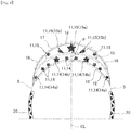
- the low compression part 10 is, as shown in detail in FIG.
- a plurality high compression parts 11, 11 ... are formed discretely respectively along the inside curve 12 and outside curve 13.
- the high compression parts 11 ... (14 %) formed along the inside curve 12 are arranged over an entire length of the inside curve 12, and the high compression parts 11 ... (15 %) formed along the outside curve 13 are arranged at a center part of the outside curve 13 and are not arranged at both end parts of the outside curve 13.
- the low compression part 10 is partitioned by the inside curve 12 and outside curve 13 to form a crescent shape that has a planar shape along the substantially width direction of the sanitary napkin 1 and a central part that swells on a front end side of the sanitary napkin 1. That is, the low compression part 10 is formed bilaterally symmetrically with respect to a central line CL in the longitudinal direction of the sanitary napkin 1 and is formed such that on the central line CL in the longitudinal direction, a part where the clearance in the longitudinal direction of napkin of the inside curve 12 and outside curve 13 becomes a maximum is located, and, as goes toward both side parts of the sanitary napkin 1, the clearance becomes gradually smaller.
- a dimension B in the napkin width direction of the low compression part 10 is formed smaller than the clearance between the side nonwoven fabrics 7, 7 on both sides and at 40 to 80%, preferably 50 to 70% relative to the width of the absorber.
- the width dimension B is smaller than 40% relative to the width of the absorber, when the absorber 4 is deformed, the low compression part 10 is difficult to work as the base point, and when the width dimension B exceeds 80% of the width of the absorber, the absorber 4 becomes too hard due to the low compression part 10 to result in generating extraneous feeling in wearing.
- a dimension L in the longitudinal direction of the sanitary napkin on a center line CL in the longitudinal direction of the sanitary napkin 1 is set to 5 to 20 mm, and desirably to 10 to 15 mm.
- the longitudinal dimension L is smaller than 5 mm, the effect of enhancing the rigidity due to the low compression part 10 is difficult to obtain, and when the longitudinal dimension L exceeds 20 mm, the absorber 4 becomes too hard to result in feeling extraneous feeling in wearing.
- the low compression part 10 is formed between a front end side than a site corresponding to the body liquid excretion part H of a wearer, specifically a front end side than a front end of the center high part 6, and more specifically a front end side than the wing-like flap W formed at both side parts, and a front end of the absorber 4.
- the sanitary napkin 1 may deform along the roundness of a front part of a body on a front end side than a groin part of the wearer.
- a clearance Y between the low compression part 10 and a front end of the absorber 4 is set to 5 to 30 mm, and preferably to 10 to 20 mm.
- the clearance Y is smaller than 5 mm, the effect of deforming a front end part of the absorber 4 with the low compression part 10 as the base point is difficult to obtain, and when the clearance Y exceeds 30 mm, the wrinkle or twists tend to occur on a front end side than the low compression part 10.
- the high compression parts 11, 11 ... are dot-like compression parts formed within the low compression part 10 partitioned by the inside curve 12 and outside curve 13 and formed with a compression depth deeper than that of the low compression part 10.
- the high compression parts 11 ... are arranged respectively along the inside curve 12 and outside curve 13. That the high compression part 11 is arranged along the inside curve 12 or outside curve 13 means whether a periphery of the high compression part 11 is arranged so as to contact with the inside curve 12 or outside curve 13, or if not contact with the respective curves 12, 13, is arranged on the respective curved line sides, with the center line drawn along a center of the clearance part of the inside curve 12 and the outside curve 13 of the low compression part 10 as a boundary.
- one arranged so as to contact with the inside curve 12 are the high compression parts 11 formed along the inside curve 12.
- the low compression part 10 is, as shown in FIG. 4 , partitioned into: a high compression part arrangement region 16 on the inside in which a plurality of high compression parts 14, 14 ... are discretely arranged over a substantially entire length of the inside curve 12; a high compression part arrangement region 17 on the outside in which a plurality of high compression parts 15, 15 ... are discretely arranged concentrated at a center part of the outside curve 13; and a high compression part absent region 18 where in each of both sides of the outside curve 13, a high compression part is not arranged.
- the clearances along the inside curve 12 of the adjacent high compression parts 14, 14 are set to substantially the same, or a ratio of the smallest clearance and the largest clearance is set to three times or smaller, preferably 2.5 times or smaller.
- the rigidity due to the high compression parts 14 ... may be intensified substantially uniformly over a substantially entire length of the inside curve 12.
- the number of the high compression parts 14 ... formed along the inside curve 12 is set to 4 to 20, preferably to 6 to 14. As shown in FIG. 4 , it is preferable that the high compression parts 14 formed along the inside curve 12 are not arranged on the central line CL in the longitudinal direction of the sanitary napkin 1 but are arranged bilaterally symmetrically on both sides of the central line CL.
- a length along the outside curve 13 of the high compression part arrangement region 17 is set to 30 to 70% of an entire length of the outside curve 13, and preferably to 40 to 60%.
- the length of the high compression part arrangement region 17 is smaller than 30% of an entire length of the outside curve 13, a sufficient enhancement effect due to the high compression parts 15 is not desired, and when the length exceeds 70% of the entire length of the outer curve 13, the high compression part absent region 18 of the both side parts becomes too small to be difficult to generate deformation of front both side parts of the sanitary napkin 1.
- the number of the high compression parts 15 arranged in the high compression part arrangement region 17 is set to 3 to 15, and preferably to 3 to 7.
- a pattern in which the high compression parts 15 are arranged on the central line CL in the longitudinal direction of the sanitary napkin 1, and one or a plurality of high compression parts 15 are bilaterally symmetrically arranged on both sides thereof is preferred.
- both sides tend to curve in the width direction to result in fitting to a shape of the body.
- the high compression parts 14 formed along the inside curve 12, and the high compression parts 15 formed along the outside curve 13 are preferably arranged to a maximum extent in zigzags at positions that are not overlapped in radial directions of the inside curve 12 and outside curve 13. Thereby, when these high compression parts 14, 15 are arranged at positions that overlap in the radial direction, the generation of the vertical wrinkle or the like may be prevented. By the way, the high compression parts 14 and 15 may overlap partially in the radial direction or may generate a slight gap.
- the inside curve 12 is enhanced in the rigidity over an entire length due to the high compression parts 14 formed along the inside curve 12, and the center part of the outside curve 13 is enhanced in the rigidity by the high compression parts 15 formed along the outside curve 13, with these curved parts of which rigidity is heightened as a base point, the sanitary napkin 1 tends to curve in the longitudinal direction, and due to rise-up of the front side along the inside curve 12, tends to deform along the roundness in the anteroposterior direction of the body.
- both side parts on the front side than the low compression part 10 of the sanitary napkin 1 tends to curve on a skin side and tends to deform along the roundness in the width direction of the body.
- the front side of the sanitary napkin 1 tends to deform along the roundness in the anteroposterior direction and the roundness in the width direction, the sanitary napkin 1 fits to a skin surface to be difficult to generate twists or leakage.
- the vertical wrinkle tends to occur along the longitudinal direction at the center part in the width direction.
- the high compression part arrangement region 17 is provided at the center part of the outside curve 13, the center part in the width direction is reinforced by the high compression part 15 of the high compression part arrangement region 17, may suppress occurrence of the vertical wrinkle and may maintain the wearing feeling excellent.
- the high compression parts 11 are discretely arranged respectively along the inside curve 12 and outside curve 13, extraneous feeling in wearing due to enhanced rigidity by the high compression part 11 may be alleviated, and the sanitary napkin 1 tends to be deformed along the roundness in the anteroposterior direction of the body, in addition thereto, tends to be deformed along the roundness in the width of the body.
- the high compression part 15a arranged on the center line CL in the longitudinal direction of the sanitary napkin 1 preferably has a maximum area among all high compression parts 11 ... formed within the low compression part 10.
- both side parts tend to deform along the roundness of the body with the high compression part 15a of the maximum area as a base point.
- An area of the high compression part 15a of the maximum area is preferably set to about 5 times to 10 times an area of the smallest high compression part 11.
- the high compression part 15a of the maximum area is preferably formed, as shown in FIG. 4 , in a planar shape having a plurality of convex parts projected toward outside (a star shape in the illustrated drawing) such as a polygonal shape, a star shape or a flower shape, and when the high compression part 15a at this time is arranged such that the convex part contacts with a center of the outside curve 13, both side parts from the center part in the width direction preferably tends to be curved and deformed with a convex part in contact with the outside curve 13 of the high compression part 15a of the maximum area as a base point.
- a star shape in the illustrated drawing such as a polygonal shape, a star shape or a flower shape
- the high compression parts 15 formed along the outside curve 13 have a planar shape long in one direction and contain a high compression part 15b in which a long axis direction is arranged inclined diagonally relative to a longitudinal direction line (a central line CL in the longitudinal direction) of the sanitary napkin 1.
- the high compression parts 15b are preferably arranged respectively on both sides of the high compression part 15a of the maximum area arranged at the center part in the width direction.
- the high compression part 15b is preferably arranged, as in the illustrated example, such that an inside in the width direction inclines toward a center side of the sanitary napkin 1. At this time, an angle ⁇ formed between the long axis of the high compression part 15b and the center line CL in the longitudinal direction of the sanitary napkin 1 is set to 30 to 60°, in particular, preferably to 40 to 50°.
- the high compression part 15b thus arranged is provided on both sides of the center in the width direction, the low compression part 10 region tends to further curve along the width direction with the high compression part 15b as a base point.
- a planar shape of the high compression part 15b may be any one of ones having a planar shape longer in one direction such as a drip shape, a long circle, an ellipse, or a rectangular shape.
- a drip shape in which one side in the longitudinal direction is formed with a width wider than the other side is preferable.
- the force tends to work on the outside curve 13 side, and the sanitary napkin 1 tends to curve along the outside curve 13.
- the high compression parts 14 ... formed along the inside curve 12 may be formed with substantially the same area over an entire length, or, as shown in FIG. 4 , may be formed with a partially relatively large area.
- the high compression parts 14 formed along the inside curve 12 are arranged at positions that do not overlap with the high compression parts 15 formed along the outside curve 13 in radial directions of the inside curve 12 and outside curve 13, and arranged substantially coinciding with the clearance part of the adjacent high compression parts 15, 15 formed along the outside curve 13, however, among the high compression parts 14 ...
- the high compression part 14b arranged at a position corresponding to a part having a large clearance of the adjacent high compression parts 15, 15 formed along the outside curve 13 may be formed with a relatively large area in accordance with the clearance.
- the rigidity due to the high compression parts 14 ... formed along the inside curve 12 within the low compression part 10 and the rigidity due to the high compression parts 15 ... formed along the outside curve 13 complement each other to be able to prevent occurrence of unnecessary wrinkle.
- the compressed grooves are constituted of :front side longitudinal direction compressed grooves 20, 20 that are arranged spaced on a back end side of the sanitary napkin 1 than the low compression part 10 and continuously formed along the substantially longitudinal direction of the napkin 1 respectively on both side parts over from a region containing a site corresponding to the body liquid excretion part H to a region containing a site corresponding to a hip part groove; back side longitudinal direction compressed grooves 21, 21 that are arranged spaced on a back side of the front side longitudinal direction compressed groove 20, and are continuously formed along the substantially longitudinal direction of the napkin 1 respectively on both side parts of a site corresponding to a back end part of a hip part groove; and a back end curve-shaped compressed groove 22 that is arranged spaced on a back side of the back side longitudinal direction compressed grooves 21, 21, crosses the longitudinal direction center line CL of the napkin 1 in the width direction, and is formed of a curved shape swelling toward a back direction.
- These compressed grooves 20 to 22 are obtained by
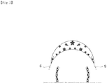
- the front longitudinal direction compressed grooves 20, 20 arranged adjacent on a back side of the low compression part 10 are, as shown in FIG. 4 , desirably arranged such that a front end part is located on an extension line S of both ends of the low compression part 10.
- a front end part of the front longitudinal direction compressed groove 20 is arranged on the extension line S like this, wrinkles occurring along the extension line S when the low compression part 10 is deformed along the roundness of the body may be suppressed.
- FIG. 4 The front longitudinal direction compressed grooves 20, 20 arranged adjacent on a back side of the low compression part 10 are, as shown in FIG. 4 , desirably arranged such that a front end part is located on an extension line S of both ends of the low compression part 10.
- the extension line S of both ends of the low compression part 10 is a tangent line at both ends of the low compression part 10 of the center line going through a center of a spaced part between the inside curve 12 and outside curve 13 of the low compression part 10. Furthermore, that a front end part of the front longitudinal direction compressed groove 20 is located on the extension line S means that the extension line S goes through within the groove width of the front end part of the front longitudinal direction compressed groove 20.
- a sum total of areas of the high compression parts 14 ... formed along the inside curve 12 and a sum total of areas of the high compression parts 15 ... formed along the outside curve 13 are preferably set to substantial the same. That these areas are substantially the same is that an area of one side is within ⁇ 5%, and preferably within ⁇ 3% of the other area side.
- the rigidity enhanced by the high compression parts 14, 15 becomes substantially the same between the inside curve 12 and outside curve, the low compression part 10 tends to deform along the roundness of the body to result in improving the fitting property.
- the low compression part 10 is provided only on a front side of the sanitary napkin 1 and on a back side, the back end curve-shaped compressed groove 22 with constant groove width formed of a curved shape swelling toward a back direction is arranged.
- the back end curve-shaped compressed groove 22 with constant groove width formed of a curved shape swelling toward a back direction is arranged.
- a concave back low compression part 30 obtained by denting, from a skin-contact surface side, a closed region part partitioned by a back inside curve 32 formed of a curved line swelling on a back end side of a sanitary napkin 1, and a back outside curve 33 that is located on a back end side than the back inside curve 32, formed of a curved line swelling on a back end side of the sanitary napkin 1, and has both ends that are respectively connected the both ends of the back inside curve 32 is formed; and, in the back low compression part 30, a plurality of back high compression parts 31 are discretely formed respectively along the back inside curve 32 and back outside curve 33, wherein the back high compression parts 34 formed along the back inside curve 32 are arranged over an entire length of the back inside curve 32, and the back high compression parts 35 formed along the back outside curve 33 are arranged at a center
Landscapes
- Health & Medical Sciences (AREA)
- Epidemiology (AREA)
- Engineering & Computer Science (AREA)
- Biomedical Technology (AREA)
- Heart & Thoracic Surgery (AREA)
- Vascular Medicine (AREA)
- Life Sciences & Earth Sciences (AREA)
- Animal Behavior & Ethology (AREA)
- General Health & Medical Sciences (AREA)
- Public Health (AREA)
- Veterinary Medicine (AREA)
- Physics & Mathematics (AREA)
- Fluid Mechanics (AREA)
- Absorbent Articles And Supports Therefor (AREA)
- Orthopedics, Nursing, And Contraception (AREA)
Abstract
Description
- The present invention relates to an absorbent article that is used mainly in sanitary napkins, vaginal discharge sheets, incontinence pads, or toiletries, in more detail, to an absorbent article in which a substantially crescent shape compression part is formed by denting from a skin-contact surface side in a plan view.
- So far, as absorbent articles such as pantiliners, sanitary napkins, and incontinence pads, ones in which an absorber made of cotton-like pulp or the like is interposed between an impermeable back-surface sheet such as a polyethylene sheet or a polyethylene sheet laminate nonwoven fabric and a permeable front sheet such as a nonwoven fabric or a permeable plastic sheet are known.
- Since this kind of absorbent articles have experienced various improvements, in order to prevent leakage of body liquid and to make it easy for an absorbent article to deform along a shape of the body in wearing, there are technologies for forming the compression part dented from a skin-contact surface side to a non-contact skin side into various forms.
- For example, in
Patent Literature 1 below, a technology of forming a circular emboss groove toward a front side on a back side of an absorber is proposed. Furthermore, inPatent Literature 2 below, an absorbent article that includes a front compressed groove extending in the width direction in a front region and a pair of vertical compressed grooves extending in the longitudinal direction on both side parts along the longitudinal direction in a region facing an excretion part, wherein the front compressed grooves and each of the vertical compressed grooves are communicated while forming a bundling part bundled toward the inside in the width direction, and the front compressed grooves have a dented part dented toward a back side at a center part in the width direction is proposed. -
- Patent Literature 1:
JP H11-113955 A - Patent Literature 2:
JP 2015-97719 A - In one described in the
Patent Literature 1, it is considered that by deforming the absorbent article in the longitudinal direction with the circular emboss groove as a base point, the absorbent article tends to follow roundness in an anteroposterior direction of a body. However, because there is no consideration of the deformation along the roundness in the width direction of the body, the fitting property to the body is insufficient and there was fear of generation of twists or leakage. - Furthermore, in the absorbent article described in the
Patent Literature 2, a front compressed groove has a circular right convex compressed groove protruded in convex to a right diagonal front direction and a circular left convex compressed groove protruded in convex to a left diagonal front direction, wherein since the right convex compressed groove and left convex compressed groove intersect and are connected in conjunction at a dented part dented in a V-shape at a central line, when the central part bends in the width direction with the dented part as a base point, a wrinkle in the vertical direction tended to occur in the front part. Furthermore, since the circular convex compressed grooves protruded in convex in a diagonal front direction respectively in left and right are formed, it is considered that the rigidity of front both side parts is enhanced by the compressed groove and front both side parts become difficult to deform along the roundness in the width direction of the body. Therefore, there is a fear that a gap is generated between a skin surface and the absorbent article to result in causing twists or leakage. - There, a main problem of the present invention is to provide an absorbent article that makes it easy to deform along a shape of the body and makes it difficult to generate twists or leakage.
- As the present invention according to
Claim 1 for solving the problem, in an absorbent article in which an absorber is interposed between a permeable front-surface sheet and a non-permeable back-surface sheet, an absorbent article,
wherein on a skin-contact surface on a front side of the absorbent article, in a plan view, a concave low compression part obtained by denting, from a skin-contact surface side, a closed region part partitioned by an inside curve formed of a curved line swelling on a front end side of the absorbent article, and an outside curve that is located on a front end side than the inside curve, formed of a curved line swelling on a front end side of the absorbent article, and has both ends that are respectively connected the both ends of the inside curve is formed; and,
in the low compression part, a plurality of high compression parts is discretely formed respectively along the inside curve and outside curve,
wherein the high compression parts formed along the inside curve are arranged over an entire length of the inside curve, and the high compression parts formed along the outside curve are arranged at a center part of the outside curve and are not arranged at both end parts of the outside curve is provided. - In the invention according to
Claim 1, since the inside curve is toughened over an entire length by the high compression part arranged over an entire length of the inside curve, and the central part of the outside curve is toughened by the high compression part arranged at the central part of the outside curve, the absorbent article tends to curve in the longitudinal direction with these toughened curved parts as a base point, and a front side rises up along the inside curve, thus, the absorbent article tends to deform along the roundness in the anteroposterior direction of the body. Furthermore, since the high compression part is not arranged to both end parts of the outside curve, the rigidity is degraded relative to a region where the high compression part is formed, therefore both side parts on a front side than the low compression part tends to curve on a skin side, thus, a front part of the absorbent article tends to deform along the roundness in the width direction of the body. Thus, since the front side of the absorbent article tends to deform along the roundness in the anteroposterior direction and the roundness in the width direction, the absorbent article fits a skin surface and becomes difficult to generate twists or leakage. - Furthermore, when the absorbent article deforms along the roundness in the width direction of the body, a vertical wrinkle tends to occur along the longitudinal direction at the central part in the width direction. However, in the absorbent article according to the present invention, since the high compression parts are concentrated at the central part of the outside curve, the vertical wrinkle may be suppressed from occurring and wearing feeling may be kept excellent.
- Furthermore, since a plurality of the high compression parts are discretely arranged respectively along the inside curve and outside curve, extraneous feeling in wearing of a part hardened by the high compression part may be alleviated, and since, in addition to that the absorbent article deforms along the roundness in the anteroposterior direction of the body, a gap is provided between the high compression parts, the absorbent article tends to deform along the roundness in the width direction of the body.
- As a present invention according to
Claim 2, the absorbent article described inClaim 1 that has the low compression part of which planar shape forms a crescent shape is provided. - Since a planar shape of the low compression part is formed in a crescent shape in the invention of the
Claim 2, due to the low compression part, the rigidity of the central part in the width direction is formed high, and the rigidity of both side parts in the width direction is formed low. Therefore, the absorbent article tends to deform along the roundness in the width direction of the body. - As a present invention according to
Claim 3, the absorbent article according to any one ofClaims - According to an invention of the
Claim 3, since among the high compression parts formed along the outside, the high compression part arranged at the center in the width direction of the absorbent article is formed so as to have a maximum area, with the high compression part of the maximum area as a base point, both side parts tend to deform along the roundness in the width direction of the body. - As a present invention according to
Claim 4, the absorbent article according to any one ofClaims 1 to 3 in which the high compression parts formed along the outside curve contain ones that have a planar shape long in one direction and in which a long axis direction is arranged inclined diagonally relative to a longitudinal direction line of the absorbent article is provided. - According to an invention of the
Claim 4, as the high compression parts formed along the outside curve, one that has a planar shape long in one direction and in which the long axis direction is arranged inclined diagonally relative to the longitudinal direction line of the absorbent article is contained. When the long axis direction of the high compression part is made not to coincide with the width direction of the absorbent article, the high compression part prevents from being disturbed to curve along the width direction of the body, and when the long axis direction of the high compression part is made not to coincide with the longitudinal direction of the absorbent article, the vertical wrinkle is prevented from occurring in the absorbent article with the high compression part as a base point. - As a present invention according to
Claim 5, the absorbent article according to any one ofClaims 1 to 4 in which among the high compression parts formed along the inside curve, the high compression part arranged at a position corresponding to a part having a large gap of adjacent high compression parts formed along the outside curve is formed with a relatively large area in accordance with its clearance. - In the invention according to the
Claim 5, among the high compression parts formed along the inside curve, the high compression part arranged at a position corresponding to a part having a large clearance between adjacent high compression parts formed along the outside curve is preferably formed relatively large in accordance with the clearance, thereby the rigidity due to the high compression parts formed along the inside curve and the rigidity due to the high compression parts formed along the outside curve in the low compression part complement each other to be able to prevent unnecessary wrinkle from occurring. - As a present invention according to
Claim 6, the absorbent article according to any one ofClaims 1 to 5 in which when spaced on a back end side of the absorbent article than the low compression part, a right and left pair of longitudinal direction compressed grooves are formed along in the longitudinal direction respectively on both side parts, and front end parts of the longitudinal direction compressed groove are arranged on an extension line of both ends of the low compression part is provided. - In the invention according to
Claim 6, when spaced on a back end side of the absorbent article than the low compression part, a right and left pair of longitudinal direction compressed grooves are formed along the longitudinal direction respectively on both side parts, front end parts of the longitudinal direction compressed groove are located on an extension line of both ends of the low compression part. Thus, the vertical wrinkle that tends to occur when the longitudinal direction compressed groove is not present on the extension line of both ends of the low compression part may be prevented and the absorbent article tends to curve along the inside curve. - As a present invention according to
Claim 7, the absorbent article according to any one ofClaims 1 to 6 in which a sum total of areas of the high compression parts formed along the inside curve and a sum total of areas of the high compression parts formed along the outside curve are substantially the same is provided. - In the invention according to
Claim 7, when the high compression parts formed along the inside curve and the high compression parts formed along the outside curve are formed with substantially the same sum total area, since the rigidity is not different but substantially the same between the inside curve and outside curve, the low compression part tends to fit the roundness of the body. - As a present invention according to Claim 8, the absorbent article according to any one of
Claims 1 to 7 in which on a skin-contact surface on a back side of the absorbent article, in a plan view, a concave back low compression part is formed by denting, from a skin-contact surface side, a closed region part partitioned by a back inside curve formed of a curved line swelling on a back end side of the absorbent article, and a back outside curve that is located on a back end side than the back inside curve and made of a curved line swelling on a back end side of the absorbent article and has both ends to which both ends of the back inside curve are respectively connected is formed; and
a plurality of back high compression parts is discretely formed respectively along the back inside curve and back outside curve in the back low compression part;
wherein the back high compression parts formed along the back inside curve are arranged over an entire length of the back inside curve; and
the back high compression parts formed along the back outside curve are arranged at a center part of the back outside curve and are not arranged at both end parts of the back outside curve is provided. - According to the invention of the Claim 8, by providing the low compression parts similarly on a back side of the absorbent article, a back part is made easy to deform along the roundness of the body to prevent the twists or leakage of the back part.
- As was detailed in the above, according to the present invention, an absorbent article that may be readily deformed along a shape of a body and is difficult to generate twists or leakage may be provided.
-
-
FIG. 1 is a partially broken development view of asanitary napkin 1 according to the present invention. -
FIG. 2 is an arrow view taken along a II-II line ofFIG. 1 . -
FIG. 3 is an arrow view taken along a III-III line ofFIG. 1 . -
FIG. 4 is an enlarged perspective view of alow compression part 10. -
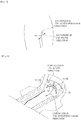
FIG. 5 is a front side perspective view of a groin part of a human body. -
FIG. 6 is a perspective view of asanitary napkin 1 showing a deformation state in wearing. -
FIG.7 is an enlarged plan view of a compressed groove that is not contained in the present invention. - FIG. 8 is a development view of a
sanitary napkin 1 according to another embodiment. - In what follows, an embodiment of the present invention will be detailed with reference to the drawings.
- A
sanitary napkin 1 according to the present invention includes, as shown inFIGs. 1 to 3 , an impermeable back-surface sheet 2 made of a polyethylene sheet or the like, a permeable front-surface sheet 3 that rapidly passes mensural blood or vaginal discharge (hereinafter, referred to as body liquid as a whole), an absorber 4 made of cotton pulp or synthetic pulp interposed between these bothsheets nonwoven fabric 7 provided over a substantially entire length along the longitudinal direction of both end parts on a skin-contact surface side, and in the surrounding of theabsorber 4, outer peripheral parts of the impermeable back-surface sheet 2 and permeable front-surface sheet 3 are connected by joining means such as an adhesive such as hot melt, heat seal, or ultrasonic seal at upper and lower end edge parts thereof, further, the impermeable back-surface sheet 2 and the sidenonwoven fabric 7 extending on a lateral side than theabsorber 4 are connected by joining means such as an adhesive such as a hot melt, heat seal or ultrasonic seal at both side edge parts, thus, a flap part in which the absorber is not interposed is formed. By the way, in an illustrated example, in order to improve shape retention and diffusibility of theabsorber 4, theabsorber 4 is surrounded by awrapping sheet 5 made of crepe sheet or nonwoven fabric, however, thewrapping sheet 5 may not be provided. Furthermore, though not shown in the drawing, adjacent on a non-skin side of the permeable front-surface sheet 3, a second sheet made of a hydrophilic nonwoven fabric of substantially the same shape with the permeable front-surface sheet 3 may be provided. - In what follows, when a structure of the
sanitary napkin 1 is described in more detail,
although, as the impermeable back-surface sheet 2, a sheet material that has at least a water blocking property such as polyethylene is used, one having moisture permeability is desirably used from the viewpoint of stuffiness prevention property. As the water-blocking/moisture permeable sheet material, a micro-porous sheet obtained in such a manner that an inorganic filler is molten and kneaded in an olefin-based resin such as polyethylene or polypropylene, followed by molding into a sheet, further followed by stretching in a uniaxial or biaxial direction is preferably used. On a non-skin-contact surface (external surface) of the impermeable back-surface sheet 2, along the longitudinal direction of the napkin, one or a plurality of stripes of adhesive layers (not shown in the drawing) are formed so as to fix thesanitary napkin 1 on an underwear in wearing on the body. As the impermeable back-surface sheet 2, a polylaminated nonwoven fabric obtained by laminating a plastic film and a non-woven fabric may be used. - Then, as the permeable front-
surface sheet 3, a perforated or non-perforated nonwoven fabric or a porous plastic sheet may be preferably used. As a raw-material fiber that constitutes the non-woven fabric, other than synthetic fibers such as olefin-based fibers such as polyethylene or polypropylene fibers, polyester-based fibers or polyamide-based fibers, recycled fibers such as rayon or cupra, or natural fibers such as cotton may be used, and nonwoven fabrics obtained according to an appropriate processing method such as a spunlace method, a spunbond method, a thermal bond method, a melt blown method, or a needle punch method may be used. Among these processing methods, the spunlace method is excellent in the point of having rich flexibility and draping property, and the thermal bond method is excellent in the point of having bulkiness and high compression restorability. When many permeable pores are formed in the permeable front-surface sheet 3, the body liquid is speedily absorbed to result in being excellent in dry touch property. Although the fiber of the nonwoven fabric may be any of a long fiber or a short fiber, in order to show the drape of towel cloth, the short fiber is preferably used. Furthermore, in order to make an emboss treatment easy, the olefin-based fiber such as polyethylene or polypropylene having relatively low melting point is preferably used. Still furthermore, a composite fiber of a core-sheath type fiber having a high melting point fiber as a core and a low melting point fiber as a sheath, a side-by-side type fiber, or a split type fiber may be also preferably used. - The
absorber 4 interposed between the impermeable back-surface sheet 2 and the permeable front-surface sheet 3 is constituted of, for example, cotton-like pulp and an absorbent polymer. The absorbent polymer is mixed in the pulp that constitutes the absorber as, for example, particulate powder. As the pulp, chemical pulp obtained from the timber, cellulose fibers such as molten pulp, and artificial cellulose fibers such as rayon, acetate can be used, and the softwood pulp having a fiber length longer than that of the hardwood pulp is preferably used from the viewpoint of function and price. - Furthermore, the
absorber 4 may be mixed with the synthetic fiber. As the synthetic fiber, for example, olefin-based synthetic fibers such as polyethylene or polypropylene, polyester-based synthetic fibers such as polyethylene terephthalate or polybutylene terephthalate, amide-based synthetic fibers such as nylon, and copolymers of these may be used, or ones obtained by mixing two kinds of these may be used. Still furthermore, a composite fiber such as a core-sheath type fiber having a high melting point fiber as a core and a low melting point fiber as a sheath, a side-by-side type fiber, or a split-type fiber may be also used. When the synthetic fiber is a hydrophobic fiber, one that is surface-treated with a hydrophilic agent is desirably used to impart the hydrophilicity to the body liquid. - As shown in
FIG. 1 andFIG. 2 , it is preferable to provide a centerhigh part 6 of the absorber of which thickness is increased on a skin side in a region containing a site corresponding to a body liquid excretion part H of theabsorber 4. The centerhigh part 6 is arranged adjacent to a skin side surface of theabsorber 4 and at a central part in the width direction of theabsorber 4, and is formed with a width dimension and a longitudinal dimension smaller than those of theabsorber 4. When a thickness of the centerhigh part 6 is too thick, the rigidity increases to degrade the adhesiveness to the body, and when the thickness is too thin, the adhesiveness with the body liquid excretion part H is degraded. Therefore, the thickness is set to 3 to 25 mm, and preferably to 5 to 18 mm. - The center
high part 6 is arranged in a region that contains a site corresponding to at least the body liquid excretion part H of a wearer. The centerhigh part 6 may be formed into a slender shape continuing over from a region containing a site corresponding to a body liquid excretion part H to a region containing a site corresponding to a hip part groove, or may be arranged only in a region containing a site corresponding to the body liquid excretion part H and may not be arranged in a region containing a site corresponding to a hip part groove on a back side than this. - When the center
high part 6 is formed into a slender shape continuing over from a region containing a site corresponding to the body liquid excretion part H to a region containing a site corresponding to a hip part groove, on a back side of the site corresponding to the body liquid excretion part H, a narrow width part in which contour lines on both sides are formed by swelling on the inside in the width direction is preferably provided. By providing the narrow width part, the absorbent article tends to fit also to fine irregularities formed on a skin surface over from a back end of the body liquid excretion part H to a start position of the hip groove to be able to improve the adhesiveness with the skin surface. - The center
high part 6 contains at least the pulp fiber and synthetic fiber, and ones obtained by mixing in terms of weight at a ratio of the pulp fiber: synthetic fiber of 80 to 20: 20 to 80, and preferably of 40 to 60: 60 to 40 are desirable. Furthermore, the centerhigh part 6 may contain an absorbent polymer. As the absorbent polymer, for example, crosslinked polyacrylates, self-crosslinked polyacrylates, saponified products of acrylic acid ester-vinyl acetate copolymer crosslinked products, isobutylene/maleic anhydride copolymer crosslinked products, crosslinked polysulfonates, and ones obtained by partially crosslinking water-swelling polymers such as polyethylene oxide or polyacrylamide are given. Among these, ones based on acrylic acid or acrylate having excellent amount of water absorption and water absorption speed are preferable. A water-absorbing power and absorption speed may be adjusted by adjusting a crosslinking density and a crosslinking density gradient in the production process of the absorbent polymer having water absorption performance. When a blending amount is increased from the necessity of promoting permeation of the centerhigh part 6 to theabsorber 4 side, a so-called gel blocking phenomenon occurs. Therefore, the absorbent polymer is desirably blended at a ratio of 1 to 10% in terms of weight relative to a total weight of the pulp fiber and synthetic fiber. By the way, when the content of the absorbent polymer exceeds 50%, tangling between pulp fibers becomes deficient to tend to undesirably cause degradation of the sheet strength to result in causing breakage or crack. - A width dimension of the permeable front-
surface sheet 3 is set to, in an illustrated example, as shown in cross-section diagrams ofFIG. 2 and FIG. 3 , a slightly longer than a width of theabsorber 4 to cover only theabsorber 4, and, outside thereof, a sidenonwoven fabric 7 separate from the permeable front-surface sheet 3, a sidenonwoven fabric 7 that specifically prevents permeation of mensural blood or vaginal discharge, or in accordance with an object of enhancing skin contact feeling, a sidenonwoven fabric 7 constituted with appropriately water-repellent treated or hydrophilic treated nonwoven fabric raw material is provided. As suchside nonwoven fabric 7, ones formed according to an appropriate processing method with natural fibers, synthetic fibers or recycled fibers as a raw material may be used. However, in order to make free from stiff feeling and to prevent the stuffiness, a nonwoven fabric of which basis weight is suppressed to impart air permeability is preferably used. Specifically, a nonwoven fabric that is produced with a basis weight controlled to 13 to 23 g/m2 is desirably used, and, in order to secure prevention of permeation of the body liquid, water-repellent treated nonwoven fabrics coated with silicone-based, paraffin-based, or alkyl chromic chloride-based water repellent agent may be preferably used. - In the side
nonwoven fabric 7, as shown inFIG. 2 and FIG. 3 , an outside part than an intermediate part in the width direction is adhered with an adhesive such as hot-melt over a range from a predetermined inside position to an outer edge of the non-permeable back-surface sheet 2, from the sidenonwoven fabric 7, the impermeable buck-surface sheet 2 and the laminate sheet part, a flap part where theabsorber 4 is not interposed on both side parts of theabsorber 4 is formed. In the flap part, a left and right pair of wing-like flaps W, W are formed at a position of absorber side part substantially corresponding to the body liquid excretion part H, and at a position on a hip part side than this (back side) , hip-hold flaps WB, WB may be formed. On each of outer surface sides of these wing-like flaps W, W and hip-hold flaps WB, WB, an adhesive layer (not shown in the drawing) is provided, and, in wearing shorts, the wing-like flaps W, W are folded back on the opposite side at a folding line RL position of a basis end part, is wound to a crotch part of the short to fasten and the hip-hold flaps WB, WB are fastened to an inner surface of the short. - On the other hand, an inner side part of the side
nonwoven fabric 7 is folded into substantially two folds, and in the inside of the two-folded sheet, one or a plurality of, in the illustrated example, three thread-like elasticstretchable members FIG. 3 , adhered to theabsorber 4 side in a state once folded on the outside, thus, as shown inFIG.2 , linear solid gathers BS, BS rising on the front side while inclining toward the outside are formed in a left and right pair. - In the present
sanitary napkin 1, on a skin-contact on a front side of thesanitary napkin 1, a concavelow compression part 10 dented from an outside surface side of thepermeable front sheet 3 is formed. Thelow compression part 10 is, as shown in detail inFIG. 4 , in a plan view, formed by denting, from a skin-contact surface side (an outer surface side of the permeable front-surface sheet) toward a non-skin side (impermeable back-surface sheet 2 side), a closed region part partitioned by aninside curve 12 formed of a curved line swelling on a front end side of asanitary napkin 1 and anoutside curve 13 that is located on the front end side of thesanitary napkin 1 than theinside curve 12 and formed of a curved line swelling on the front end side of thesanitary napkin 1, and has both ends that are connected respectively to both ends of theinside curve 12. In thelow compression part 10, a pluralityhigh compression parts inside curve 12 andoutside curve 13. Thehigh compression parts 11 ... (14 ...) formed along theinside curve 12 are arranged over an entire length of theinside curve 12, and thehigh compression parts 11 ... (15 ...) formed along theoutside curve 13 are arranged at a center part of theoutside curve 13 and are not arranged at both end parts of theoutside curve 13. - The
low compression part 10 is partitioned by theinside curve 12 andoutside curve 13 to form a crescent shape that has a planar shape along the substantially width direction of thesanitary napkin 1 and a central part that swells on a front end side of thesanitary napkin 1. That is, thelow compression part 10 is formed bilaterally symmetrically with respect to a central line CL in the longitudinal direction of thesanitary napkin 1 and is formed such that on the central line CL in the longitudinal direction, a part where the clearance in the longitudinal direction of napkin of theinside curve 12 andoutside curve 13 becomes a maximum is located, and, as goes toward both side parts of thesanitary napkin 1, the clearance becomes gradually smaller. - A dimension B in the napkin width direction of the
low compression part 10 is formed smaller than the clearance between the sidenonwoven fabrics absorber 4 is deformed, thelow compression part 10 is difficult to work as the base point, and when the width dimension B exceeds 80% of the width of the absorber, theabsorber 4 becomes too hard due to thelow compression part 10 to result in generating extraneous feeling in wearing. - Furthermore, a dimension L in the longitudinal direction of the sanitary napkin on a center line CL in the longitudinal direction of the
sanitary napkin 1 is set to 5 to 20 mm, and desirably to 10 to 15 mm. When the longitudinal dimension L is smaller than 5 mm, the effect of enhancing the rigidity due to thelow compression part 10 is difficult to obtain, and when the longitudinal dimension L exceeds 20 mm, theabsorber 4 becomes too hard to result in feeling extraneous feeling in wearing. - The
low compression part 10 is formed between a front end side than a site corresponding to the body liquid excretion part H of a wearer, specifically a front end side than a front end of the centerhigh part 6, and more specifically a front end side than the wing-like flap W formed at both side parts, and a front end of theabsorber 4. Thus, thesanitary napkin 1 may deform along the roundness of a front part of a body on a front end side than a groin part of the wearer. - A clearance Y between the
low compression part 10 and a front end of theabsorber 4 is set to 5 to 30 mm, and preferably to 10 to 20 mm. When the clearance Y is smaller than 5 mm, the effect of deforming a front end part of theabsorber 4 with thelow compression part 10 as the base point is difficult to obtain, and when the clearance Y exceeds 30 mm, the wrinkle or twists tend to occur on a front end side than thelow compression part 10. - The
high compression parts low compression part 10 partitioned by theinside curve 12 andoutside curve 13 and formed with a compression depth deeper than that of thelow compression part 10. Thehigh compression parts 11 ... are arranged respectively along theinside curve 12 andoutside curve 13. That thehigh compression part 11 is arranged along theinside curve 12 oroutside curve 13 means whether a periphery of thehigh compression part 11 is arranged so as to contact with theinside curve 12 oroutside curve 13, or if not contact with therespective curves inside curve 12 and theoutside curve 13 of thelow compression part 10 as a boundary. However, among the high compression parts 14 ... formed along theinside curve 12, high compression parts 14a arranged at both end parts of theinside curve 12, due to a shorter clearance with theoutside curve 13, may exude on theoutside curve 13 side than the central line of thelow compression part 10. However, even in this case, one arranged so as to contact with theinside curve 12 are thehigh compression parts 11 formed along theinside curve 12. - The
low compression part 10 is, as shown inFIG. 4 , partitioned into: a high compressionpart arrangement region 16 on the inside in which a plurality of high compression parts 14, 14 ... are discretely arranged over a substantially entire length of theinside curve 12; a high compressionpart arrangement region 17 on the outside in which a plurality of high compression parts 15, 15 ... are discretely arranged concentrated at a center part of theoutside curve 13; and a high compression partabsent region 18 where in each of both sides of theoutside curve 13, a high compression part is not arranged. - In the high compression
part arrangement region 16 on the inside, it is better that the clearances along theinside curve 12 of the adjacent high compression parts 14, 14 are set to substantially the same, or a ratio of the smallest clearance and the largest clearance is set to three times or smaller, preferably 2.5 times or smaller. Thus, the rigidity due to the high compression parts 14 ... may be intensified substantially uniformly over a substantially entire length of theinside curve 12. - The number of the high compression parts 14 ... formed along the
inside curve 12 is set to 4 to 20, preferably to 6 to 14. As shown inFIG. 4 , it is preferable that the high compression parts 14 formed along theinside curve 12 are not arranged on the central line CL in the longitudinal direction of thesanitary napkin 1 but are arranged bilaterally symmetrically on both sides of the central line CL. - On the other hand, a length along the
outside curve 13 of the high compressionpart arrangement region 17 is set to 30 to 70% of an entire length of theoutside curve 13, and preferably to 40 to 60%. When the length of the high compressionpart arrangement region 17 is smaller than 30% of an entire length of theoutside curve 13, a sufficient enhancement effect due to the high compression parts 15 is not desired, and when the length exceeds 70% of the entire length of theouter curve 13, the high compression partabsent region 18 of the both side parts becomes too small to be difficult to generate deformation of front both side parts of thesanitary napkin 1. - The number of the high compression parts 15 arranged in the high compression
part arrangement region 17 is set to 3 to 15, and preferably to 3 to 7. In the high compressionpart arrangement region 17, a pattern in which the high compression parts 15 are arranged on the central line CL in the longitudinal direction of thesanitary napkin 1, and one or a plurality of high compression parts 15 are bilaterally symmetrically arranged on both sides thereof is preferred. When the high compression parts 15 are arranged on the central line CL in the longitudinal direction, with the central high compression parts 15 as a base point, both sides tend to curve in the width direction to result in fitting to a shape of the body. - The high compression parts 14 formed along the
inside curve 12, and the high compression parts 15 formed along theoutside curve 13 are preferably arranged to a maximum extent in zigzags at positions that are not overlapped in radial directions of theinside curve 12 andoutside curve 13. Thereby, when these high compression parts 14, 15 are arranged at positions that overlap in the radial direction, the generation of the vertical wrinkle or the like may be prevented. By the way, the high compression parts 14 and 15 may overlap partially in the radial direction or may generate a slight gap. - Since in the
sanitary napkin 1 formed with the above constitution, as shown inFIG. 5 and FIG. 6 , theinside curve 12 is enhanced in the rigidity over an entire length due to the high compression parts 14 formed along theinside curve 12, and the center part of theoutside curve 13 is enhanced in the rigidity by the high compression parts 15 formed along theoutside curve 13, with these curved parts of which rigidity is heightened as a base point, thesanitary napkin 1 tends to curve in the longitudinal direction, and due to rise-up of the front side along theinside curve 12, tends to deform along the roundness in the anteroposterior direction of the body. Furthermore, since a high compression partabsent region 18 in which the high compression part 15 is not arranged is provided to both end parts of theoutside curve 13, the rigidity degrades relatively to the high compressionpart arrangement region 17 of the central part, both side parts on the front side than thelow compression part 10 of thesanitary napkin 1 tends to curve on a skin side and tends to deform along the roundness in the width direction of the body. Thus, since the front side of thesanitary napkin 1 tends to deform along the roundness in the anteroposterior direction and the roundness in the width direction, thesanitary napkin 1 fits to a skin surface to be difficult to generate twists or leakage. - Furthermore, when the
sanitary napkin 1 is deformed along the roundness in the width direction of the body, the vertical wrinkle tends to occur along the longitudinal direction at the center part in the width direction. However, since the high compressionpart arrangement region 17 is provided at the center part of theoutside curve 13, the center part in the width direction is reinforced by the high compression part 15 of the high compressionpart arrangement region 17, may suppress occurrence of the vertical wrinkle and may maintain the wearing feeling excellent. - Furthermore, since the
high compression parts 11 are discretely arranged respectively along theinside curve 12 andoutside curve 13, extraneous feeling in wearing due to enhanced rigidity by thehigh compression part 11 may be alleviated, and thesanitary napkin 1 tends to be deformed along the roundness in the anteroposterior direction of the body, in addition thereto, tends to be deformed along the roundness in the width of the body. - As shown in
FIG. 4 , among the high compression parts 15 ... formed along theoutside curve 13, the high compression part 15a arranged on the center line CL in the longitudinal direction of thesanitary napkin 1 preferably has a maximum area among allhigh compression parts 11 ... formed within thelow compression part 10. Thus, both side parts tend to deform along the roundness of the body with the high compression part 15a of the maximum area as a base point. An area of the high compression part 15a of the maximum area is preferably set to about 5 times to 10 times an area of the smallesthigh compression part 11. - Furthermore, the high compression part 15a of the maximum area is preferably formed, as shown in
FIG. 4 , in a planar shape having a plurality of convex parts projected toward outside (a star shape in the illustrated drawing) such as a polygonal shape, a star shape or a flower shape, and when the high compression part 15a at this time is arranged such that the convex part contacts with a center of theoutside curve 13, both side parts from the center part in the width direction preferably tends to be curved and deformed with a convex part in contact with theoutside curve 13 of the high compression part 15a of the maximum area as a base point. - As shown in
FIG. 4 , it is preferable that the high compression parts 15 formed along theoutside curve 13 have a planar shape long in one direction and contain a high compression part 15b in which a long axis direction is arranged inclined diagonally relative to a longitudinal direction line (a central line CL in the longitudinal direction) of thesanitary napkin 1. The high compression parts 15b are preferably arranged respectively on both sides of the high compression part 15a of the maximum area arranged at the center part in the width direction. When the long axis direction of the high compression part 15b is not coincided with the width direction of thesanitary napkin 1, a curving deformation along the width direction of a part in which the high compression part 15b is arranged is not disturbed, and when the long axis direction of the high compression part is not coincided with the longitudinal direction of thesanitary napkin 1, the vertical wrinkle with the high compression part 15b as a base point may be prevented from occurring. - The high compression part 15b is preferably arranged, as in the illustrated example, such that an inside in the width direction inclines toward a center side of the
sanitary napkin 1. At this time, an angle α formed between the long axis of the high compression part 15b and the center line CL in the longitudinal direction of thesanitary napkin 1 is set to 30 to 60°, in particular, preferably to 40 to 50°. When the high compression part 15b thus arranged is provided on both sides of the center in the width direction, thelow compression part 10 region tends to further curve along the width direction with the high compression part 15b as a base point. - A planar shape of the high compression part 15b may be any one of ones having a planar shape longer in one direction such as a drip shape, a long circle, an ellipse, or a rectangular shape. However, as in the illustrated example, a drip shape in which one side in the longitudinal direction is formed with a width wider than the other side is preferable. At this time, as in the illustrated example, when one side formed with a larger width is arranged toward a side nearer to the outside curve 13 (the front end side of the sanitary napkin 1), the force tends to work on the
outside curve 13 side, and thesanitary napkin 1 tends to curve along theoutside curve 13. - On the other hand, the high compression parts 14 ... formed along the
inside curve 12 may be formed with substantially the same area over an entire length, or, as shown inFIG. 4 , may be formed with a partially relatively large area. Specifically, as was described above, the high compression parts 14 formed along theinside curve 12 are arranged at positions that do not overlap with the high compression parts 15 formed along theoutside curve 13 in radial directions of theinside curve 12 andoutside curve 13, and arranged substantially coinciding with the clearance part of the adjacent high compression parts 15, 15 formed along theoutside curve 13, however, among the high compression parts 14 ... formed along theinside curve 12, the high compression part 14b arranged at a position corresponding to a part having a large clearance of the adjacent high compression parts 15, 15 formed along theoutside curve 13 may be formed with a relatively large area in accordance with the clearance. Thus, since with respect to radial directions of theinside curve 12 andoutside curve 13, a part in which the rigidity is remarkably degraded due to absence of the high compression parts 14, 15 is not formed, the rigidity due to the high compression parts 14 ... formed along theinside curve 12 within thelow compression part 10 and the rigidity due to the high compression parts 15 ... formed along theoutside curve 13 complement each other to be able to prevent occurrence of unnecessary wrinkle. - In the
sanitary napkin 1, as shown inFIG. 1 , other than thelow compression part 10 formed on a front side, at a position of a proximity outside part of the centerhigh part 6, compressed grooves dented from an outer surface side of the permeable front-surface sheet 3 toward the impermeable back-surface sheet 2 may be formed. In an example specifically shown inFIG.1 , the compressed grooves are constituted of :front side longitudinal direction compressedgrooves sanitary napkin 1 than thelow compression part 10 and continuously formed along the substantially longitudinal direction of thenapkin 1 respectively on both side parts over from a region containing a site corresponding to the body liquid excretion part H to a region containing a site corresponding to a hip part groove; back side longitudinal direction compressedgrooves groove 20, and are continuously formed along the substantially longitudinal direction of thenapkin 1 respectively on both side parts of a site corresponding to a back end part of a hip part groove; and a back end curve-shapedcompressed groove 22 that is arranged spaced on a back side of the back side longitudinal direction compressedgrooves napkin 1 in the width direction, and is formed of a curved shape swelling toward a back direction. Thesecompressed grooves 20 to 22 are obtained by compressing integrally over from the permeable front-surface sheet 3 to theabsorber 4 by hot embossing from an outer surface side of the permeable front-surface sheet 3. - The front longitudinal direction compressed
grooves low compression part 10 are, as shown inFIG. 4 , desirably arranged such that a front end part is located on an extension line S of both ends of thelow compression part 10. When a front end part of the front longitudinal direction compressedgroove 20 is arranged on the extension line S like this, wrinkles occurring along the extension line S when thelow compression part 10 is deformed along the roundness of the body may be suppressed. By contrast, as shown inFIG. 7 , when the front end part of the front longitudinal direction compressedgroove 20 is not present on the extension line S of both ends of thelow compression part 10, in the illustrated example, when the front end part of the front longitudinal direction compressedgroove 20 is arranged on an inner side than the extension line S of both ends of thelow compression part 10, the wrinkles of thelow compression parts 10 deformed along the roundness of the body tend to occur along the extension line S. Furthermore, when the wrinkle occurs along the extension line S, thelow compression part 10 becomes difficult to deform. Here, the extension line S of both ends of thelow compression part 10 is a tangent line at both ends of thelow compression part 10 of the center line going through a center of a spaced part between theinside curve 12 andoutside curve 13 of thelow compression part 10. Furthermore, that a front end part of the front longitudinal direction compressedgroove 20 is located on the extension line S means that the extension line S goes through within the groove width of the front end part of the front longitudinal direction compressedgroove 20. - Next, a sum total of areas of the high compression parts 14 ... formed along the
inside curve 12 and a sum total of areas of the high compression parts 15 ... formed along theoutside curve 13 are preferably set to substantial the same. That these areas are substantially the same is that an area of one side is within ± 5%, and preferably within ± 3% of the other area side. Thus, since the rigidity enhanced by the high compression parts 14, 15 becomes substantially the same between theinside curve 12 and outside curve, thelow compression part 10 tends to deform along the roundness of the body to result in improving the fitting property. - In the above embodiment, the
low compression part 10 is provided only on a front side of thesanitary napkin 1 and on a back side, the back end curve-shapedcompressed groove 22 with constant groove width formed of a curved shape swelling toward a back direction is arranged. However, as shown in FIG. 8, in place of the back end curve-shaped compressed groove 22 (illustrated example), or spaced in a back direction of the back end curve-shapedcompressed groove 22, in a plan view, a concave back low compression part 30 obtained by denting, from a skin-contact surface side, a closed region part partitioned by a back inside curve 32 formed of a curved line swelling on a back end side of asanitary napkin 1, and a back outside curve 33 that is located on a back end side than the back inside curve 32, formed of a curved line swelling on a back end side of thesanitary napkin 1, and has both ends that are respectively connected the both ends of the back inside curve 32 is formed; and,
in the back low compression part 30, a plurality of back high compression parts 31 are discretely formed respectively along the back inside curve 32 and back outside curve 33,
wherein the back high compression parts 34 formed along the back inside curve 32 are arranged over an entire length of the back inside curve 32, and the back high compression parts 35 formed along the back outside curve 33 are arranged at a center part of the back outside curve 33 and are not arranged at both end parts of the back outside curve 33. Thus, similarly also on a back side of thesanitary napkin 1, the sanitary napkin tends to deform along the roundness in the anteroposterior direction of the body and along the roundness in the width direction and the twists or leakage becomes difficult to occur. -
- 1 ... SANITARY NAPKIN
- 2 ... IMPERMEABLE BACK-SURFACE SHEET
- 3 ... PERMEABLE FRONT-SURFACE SHEET
- 4 ... ABSORBER
- 5 ... WRAPPING SHEET
- 6 ... CENTER HIGH PART
- 7 ... SIDE NONWOVEN FABRIC
- 9 ... THREAD-LIKE ELASTIC STRECHABLE MEMBER
- 10 ... LOW COMPRESSION PART
- 11/14/15 ... HIGH COMPRESSION PART
- 12 ... INSIDE CURVE
- 13 ... OUTSIDE CURVE
- 16/17 ... HIGH COMPRESSION PART ARRANGEMENT REGION
- 18 ... HIGH COMPRESSION PART ABSENT REGION
- 20 ... FRONT LONGITUDINAL DIRECTION COMPRESSED GROOVE
- 21 ... BACK LONGITUDINAL DIRECTION COMPRESSED GROOVE
- 22 ... BACK END CURVE-SHAPED COMPRESSION GROOVE
Claims (8)
- An absorbent article comprising:an absorber interposed between a permeable front-surface sheet and an impermeable back-surface sheet,wherein on a skin-contact surface on a front side of the absorbent article, in a plan view, a concave low compression part obtained by denting, from a skin-contact surface side, a closed region part partitioned by an inside curve formed of a curved line swelling on a front end side of the absorbent article, and an outside curve that is located on a front end side than the inside curve, is formed of a curved line swelling on a front end side of the absorbent article, and has both ends to which both ends of the inside curve are respectively connected is formed; and,in the low compression part, a plurality of high compression parts is discretely formed respectively along the inside curve and outside curve,wherein the high compression parts formed along the inside curve are arranged over an entire length of the inside curve, and the high compression parts formed along the outside curve are arranged at a center part of the outside curve and are not arranged at both end parts of the outside curve.
- The absorbent article according to claim 1, wherein the low compression part has a planar shape formed into crescent shape.
- The absorbent article according to any one of claims 1 and 2, wherein, among the high compression parts formed along the outside curve, a high compression part placed at the center in the width direction of the absorbent article has a maximum area among the high compression parts.
- The absorbent article according to any one of claims 1 to 3, wherein the high compression parts formed along the outside curve contain one that has a planar shape long in one direction and is arranged such that a long axis direction is inclined diagonally relative to a longitudinal direction line of the absorbent article.
- The absorbent article according to any one of claims 1 to 4, wherein among the high compression parts formed along the inside curve, a high compression part arranged at a position corresponding to a part having a large clearance of adjacent high compression parts formed along the outside curve is formed with a relatively large area in accordance with the clearance.
- The absorbent article according to any one of claims 1 to 5, wherein when spaced on a back end side of the absorbent article than the low compression part, a right and left pair of longitudinal direction compressed grooves are formed along in the longitudinal direction respectively on both side parts, and front end parts of the longitudinal direction compressed grooves are located on an extension line of both ends of the low compression part.
- The absorbent article according to any one of claims 1 to 6, wherein a sum total of areas of the high compression parts formed along the inside curve and a sum total of areas of the high compression parts formed along the outside curve are substantially the same.
- The absorbent article according to any one of claims 1 to 7, wherein on a skin-contact surface on a back side of the absorbent article, in a plan view, a concave back low compression part is formed by denting, from a skin-contact surface side, a closed region part partitioned by a back inside curve formed of a curved line swelling on a back end side of the absorbent article, and a back outside curve that is located on a back end side than the back inside curve and made of a curved line swelling on a back end side of the absorbent article and has both ends that are connected respectively to both ends of the back inside curve is formed; and
a plurality of back high compression parts formed discretely respectively along the back inside curve and back outside curve is formed in the back low compression part,
wherein the back high compression parts formed along the back inside curve are arranged over an entire length of the back inside curve; and
the back high compression parts formed along the back outside curve are arranged at a center part of the back outside curve and are not arranged at both end parts of the back outside curve.
Applications Claiming Priority (2)
| Application Number | Priority Date | Filing Date | Title |
|---|---|---|---|
| JP2016114960A JP6404269B2 (en) | 2016-06-09 | 2016-06-09 | Absorbent articles |
| PCT/JP2017/021266 WO2017213211A1 (en) | 2016-06-09 | 2017-06-08 | Absorbent article |
Publications (3)
| Publication Number | Publication Date |
|---|---|
| EP3470038A1 true EP3470038A1 (en) | 2019-04-17 |
| EP3470038A4 EP3470038A4 (en) | 2020-01-22 |
| EP3470038B1 EP3470038B1 (en) | 2022-10-12 |
Family
ID=60578694
Family Applications (1)
| Application Number | Title | Priority Date | Filing Date |
|---|---|---|---|
| EP17810384.2A Active EP3470038B1 (en) | 2016-06-09 | 2017-06-08 | Absorbent article |
Country Status (5)
| Country | Link |
|---|---|
| US (1) | US11173075B2 (en) |
| EP (1) | EP3470038B1 (en) |
| JP (1) | JP6404269B2 (en) |
| CN (1) | CN109310553B (en) |
| WO (1) | WO2017213211A1 (en) |
Families Citing this family (1)
| Publication number | Priority date | Publication date | Assignee | Title |
|---|---|---|---|---|
| PL3342386T3 (en) * | 2016-12-27 | 2019-10-31 | Ontex Bvba | Absorbent core, articles comprising said core, and methods of making |
Family Cites Families (11)
| Publication number | Priority date | Publication date | Assignee | Title |
|---|---|---|---|---|
| JPH11113955A (en) * | 1997-10-20 | 1999-04-27 | Shiseido Co Ltd | Body fluid absorbent articles |
| JP3816458B2 (en) * | 2003-03-19 | 2006-08-30 | 大王製紙株式会社 | Absorbent articles |
| JP4593986B2 (en) * | 2004-06-30 | 2010-12-08 | 大王製紙株式会社 | Absorber |
| WO2006060526A1 (en) * | 2004-11-30 | 2006-06-08 | The Procter & Gamble Company | Absorbent article having outwardly convex longitudinal central channels for improved protection |
| EP1885315A1 (en) * | 2005-06-02 | 2008-02-13 | The Procter and Gamble Company | Absorbent article having traverse reinforcing element |
| US20080281287A1 (en) * | 2007-05-08 | 2008-11-13 | Marcelo Ana Maria Elena R | Sanitary napkin including body-facing protrusions for preventing side leakage and obliquely arranged embossed channels |
| JP5294837B2 (en) * | 2008-12-25 | 2013-09-18 | ユニ・チャーム株式会社 | Absorbent articles |
| JP5455363B2 (en) * | 2008-12-25 | 2014-03-26 | ユニ・チャーム株式会社 | Thin absorbent article |
| JP5082007B1 (en) * | 2011-09-30 | 2012-11-28 | ユニ・チャーム株式会社 | Absorbent articles |
| JP6001984B2 (en) * | 2012-10-01 | 2016-10-05 | 花王株式会社 | Absorbent articles |
| JP6360335B2 (en) * | 2014-03-27 | 2018-07-18 | 大王製紙株式会社 | Absorbent articles |
-
2016
- 2016-06-09 JP JP2016114960A patent/JP6404269B2/en active Active
-
2017
- 2017-06-08 US US16/307,704 patent/US11173075B2/en active Active
- 2017-06-08 EP EP17810384.2A patent/EP3470038B1/en active Active
- 2017-06-08 WO PCT/JP2017/021266 patent/WO2017213211A1/en not_active Ceased
- 2017-06-08 CN CN201780035586.7A patent/CN109310553B/en active Active
Also Published As
| Publication number | Publication date |
|---|---|
| EP3470038A4 (en) | 2020-01-22 |
| CN109310553A (en) | 2019-02-05 |
| US20190262193A1 (en) | 2019-08-29 |
| EP3470038B1 (en) | 2022-10-12 |
| JP6404269B2 (en) | 2018-10-10 |
| JP2017217285A (en) | 2017-12-14 |
| US11173075B2 (en) | 2021-11-16 |
| WO2017213211A1 (en) | 2017-12-14 |
| CN109310553B (en) | 2021-09-21 |
Similar Documents
| Publication | Publication Date | Title |
|---|---|---|
| US10555843B2 (en) | Absorbent article | |
| EP3470036B1 (en) | Absorbent article | |
| EP3470039B1 (en) | Absorbent article | |
| EP3653186B1 (en) | Absorbent article | |
| JP6553137B2 (en) | Absorbent articles | |
| JP2018051110A (en) | Absorbent articles | |
| KR20210062592A (en) | Absorbent articles for men | |
| JP6694734B2 (en) | Absorbent article | |
| TWM479121U (en) | Absorbent article | |
| EP3831351B1 (en) | Absorbent article | |
| CN105167915B (en) | Absorbent article | |
| JP5944953B2 (en) | Absorbent articles | |
| JP2017042383A (en) | Absorbent article | |
| US11173075B2 (en) | Absorbent article | |
| JP2016002100A5 (en) | ||
| EP4424288A1 (en) | Absorbent article | |
| JP7834949B2 (en) | Absorbent articles | |
| JP5944951B2 (en) | Absorbent articles | |
| JP7071809B2 (en) | Absorbent article | |
| JP6108428B2 (en) | Absorbent articles | |
| JP2017063917A (en) | Absorbent article |
Legal Events
| Date | Code | Title | Description |
|---|---|---|---|
| STAA | Information on the status of an ep patent application or granted ep patent |
Free format text: STATUS: THE INTERNATIONAL PUBLICATION HAS BEEN MADE |
|
| PUAI | Public reference made under article 153(3) epc to a published international application that has entered the european phase |
Free format text: ORIGINAL CODE: 0009012 |
|
| STAA | Information on the status of an ep patent application or granted ep patent |
Free format text: STATUS: REQUEST FOR EXAMINATION WAS MADE |
|
| 17P | Request for examination filed |
Effective date: 20190107 |
|
| AK | Designated contracting states |
Kind code of ref document: A1 Designated state(s): AL AT BE BG CH CY CZ DE DK EE ES FI FR GB GR HR HU IE IS IT LI LT LU LV MC MK MT NL NO PL PT RO RS SE SI SK SM TR |
|
| AX | Request for extension of the european patent |
Extension state: BA ME |
|
| DAV | Request for validation of the european patent (deleted) | ||
| DAX | Request for extension of the european patent (deleted) | ||
| A4 | Supplementary search report drawn up and despatched |
Effective date: 20191219 |
|
| RIC1 | Information provided on ipc code assigned before grant |
Ipc: A61F 13/47 20060101AFI20191213BHEP Ipc: A61F 13/533 20060101ALI20191213BHEP Ipc: A61F 13/511 20060101ALI20191213BHEP Ipc: A61F 13/475 20060101ALI20191213BHEP |
|
| REG | Reference to a national code |
Ref country code: DE Ref legal event code: R079 Ref document number: 602017062626 Country of ref document: DE Free format text: PREVIOUS MAIN CLASS: A61F0013533000 Ipc: A61F0013470000 |
|
| GRAP | Despatch of communication of intention to grant a patent |
Free format text: ORIGINAL CODE: EPIDOSNIGR1 |
|
| STAA | Information on the status of an ep patent application or granted ep patent |
Free format text: STATUS: GRANT OF PATENT IS INTENDED |
|
| RIC1 | Information provided on ipc code assigned before grant |
Ipc: A61F 13/533 20060101ALI20220329BHEP Ipc: A61F 13/511 20060101ALI20220329BHEP Ipc: A61F 13/475 20060101ALI20220329BHEP Ipc: A61F 13/47 20060101AFI20220329BHEP |
|
| INTG | Intention to grant announced |
Effective date: 20220428 |
|
| RIN1 | Information on inventor provided before grant (corrected) |
Inventor name: KONAWA, SATOKO |
|
| GRAS | Grant fee paid |
Free format text: ORIGINAL CODE: EPIDOSNIGR3 |
|
| GRAA | (expected) grant |
Free format text: ORIGINAL CODE: 0009210 |
|
| STAA | Information on the status of an ep patent application or granted ep patent |
Free format text: STATUS: THE PATENT HAS BEEN GRANTED |
|
| AK | Designated contracting states |
Kind code of ref document: B1 Designated state(s): AL AT BE BG CH CY CZ DE DK EE ES FI FR GB GR HR HU IE IS IT LI LT LU LV MC MK MT NL NO PL PT RO RS SE SI SK SM TR |
|
| REG | Reference to a national code |
Ref country code: GB Ref legal event code: FG4D |
|
| REG | Reference to a national code |
Ref country code: CH Ref legal event code: EP |
|
| REG | Reference to a national code |
Ref country code: DE Ref legal event code: R096 Ref document number: 602017062626 Country of ref document: DE |
|
| REG | Reference to a national code |
Ref country code: IE Ref legal event code: FG4D |
|
| REG | Reference to a national code |
Ref country code: AT Ref legal event code: REF Ref document number: 1523717 Country of ref document: AT Kind code of ref document: T Effective date: 20221115 |
|
| REG | Reference to a national code |
Ref country code: LT Ref legal event code: MG9D |
|
| REG | Reference to a national code |
Ref country code: NL Ref legal event code: MP Effective date: 20221012 |
|
| REG | Reference to a national code |
Ref country code: AT Ref legal event code: MK05 Ref document number: 1523717 Country of ref document: AT Kind code of ref document: T Effective date: 20221012 |
|
| PG25 | Lapsed in a contracting state [announced via postgrant information from national office to epo] |
Ref country code: NL Free format text: LAPSE BECAUSE OF FAILURE TO SUBMIT A TRANSLATION OF THE DESCRIPTION OR TO PAY THE FEE WITHIN THE PRESCRIBED TIME-LIMIT Effective date: 20221012 |
|
| PG25 | Lapsed in a contracting state [announced via postgrant information from national office to epo] |
Ref country code: SE Free format text: LAPSE BECAUSE OF FAILURE TO SUBMIT A TRANSLATION OF THE DESCRIPTION OR TO PAY THE FEE WITHIN THE PRESCRIBED TIME-LIMIT Effective date: 20221012 Ref country code: PT Free format text: LAPSE BECAUSE OF FAILURE TO SUBMIT A TRANSLATION OF THE DESCRIPTION OR TO PAY THE FEE WITHIN THE PRESCRIBED TIME-LIMIT Effective date: 20230213 Ref country code: NO Free format text: LAPSE BECAUSE OF FAILURE TO SUBMIT A TRANSLATION OF THE DESCRIPTION OR TO PAY THE FEE WITHIN THE PRESCRIBED TIME-LIMIT Effective date: 20230112 Ref country code: LT Free format text: LAPSE BECAUSE OF FAILURE TO SUBMIT A TRANSLATION OF THE DESCRIPTION OR TO PAY THE FEE WITHIN THE PRESCRIBED TIME-LIMIT Effective date: 20221012 Ref country code: FI Free format text: LAPSE BECAUSE OF FAILURE TO SUBMIT A TRANSLATION OF THE DESCRIPTION OR TO PAY THE FEE WITHIN THE PRESCRIBED TIME-LIMIT Effective date: 20221012 Ref country code: ES Free format text: LAPSE BECAUSE OF FAILURE TO SUBMIT A TRANSLATION OF THE DESCRIPTION OR TO PAY THE FEE WITHIN THE PRESCRIBED TIME-LIMIT Effective date: 20221012 Ref country code: AT Free format text: LAPSE BECAUSE OF FAILURE TO SUBMIT A TRANSLATION OF THE DESCRIPTION OR TO PAY THE FEE WITHIN THE PRESCRIBED TIME-LIMIT Effective date: 20221012 |
|
| PG25 | Lapsed in a contracting state [announced via postgrant information from national office to epo] |
Ref country code: RS Free format text: LAPSE BECAUSE OF FAILURE TO SUBMIT A TRANSLATION OF THE DESCRIPTION OR TO PAY THE FEE WITHIN THE PRESCRIBED TIME-LIMIT Effective date: 20221012 Ref country code: PL Free format text: LAPSE BECAUSE OF FAILURE TO SUBMIT A TRANSLATION OF THE DESCRIPTION OR TO PAY THE FEE WITHIN THE PRESCRIBED TIME-LIMIT Effective date: 20221012 Ref country code: LV Free format text: LAPSE BECAUSE OF FAILURE TO SUBMIT A TRANSLATION OF THE DESCRIPTION OR TO PAY THE FEE WITHIN THE PRESCRIBED TIME-LIMIT Effective date: 20221012 Ref country code: IS Free format text: LAPSE BECAUSE OF FAILURE TO SUBMIT A TRANSLATION OF THE DESCRIPTION OR TO PAY THE FEE WITHIN THE PRESCRIBED TIME-LIMIT Effective date: 20230212 Ref country code: HR Free format text: LAPSE BECAUSE OF FAILURE TO SUBMIT A TRANSLATION OF THE DESCRIPTION OR TO PAY THE FEE WITHIN THE PRESCRIBED TIME-LIMIT Effective date: 20221012 Ref country code: GR Free format text: LAPSE BECAUSE OF FAILURE TO SUBMIT A TRANSLATION OF THE DESCRIPTION OR TO PAY THE FEE WITHIN THE PRESCRIBED TIME-LIMIT Effective date: 20230113 |
|
| REG | Reference to a national code |
Ref country code: DE Ref legal event code: R097 Ref document number: 602017062626 Country of ref document: DE |
|
| REG | Reference to a national code |
Ref country code: DE Ref legal event code: R084 Ref document number: 602017062626 Country of ref document: DE |
|
| PG25 | Lapsed in a contracting state [announced via postgrant information from national office to epo] |
Ref country code: SM Free format text: LAPSE BECAUSE OF FAILURE TO SUBMIT A TRANSLATION OF THE DESCRIPTION OR TO PAY THE FEE WITHIN THE PRESCRIBED TIME-LIMIT Effective date: 20221012 Ref country code: RO Free format text: LAPSE BECAUSE OF FAILURE TO SUBMIT A TRANSLATION OF THE DESCRIPTION OR TO PAY THE FEE WITHIN THE PRESCRIBED TIME-LIMIT Effective date: 20221012 Ref country code: EE Free format text: LAPSE BECAUSE OF FAILURE TO SUBMIT A TRANSLATION OF THE DESCRIPTION OR TO PAY THE FEE WITHIN THE PRESCRIBED TIME-LIMIT Effective date: 20221012 Ref country code: DK Free format text: LAPSE BECAUSE OF FAILURE TO SUBMIT A TRANSLATION OF THE DESCRIPTION OR TO PAY THE FEE WITHIN THE PRESCRIBED TIME-LIMIT Effective date: 20221012 Ref country code: CZ Free format text: LAPSE BECAUSE OF FAILURE TO SUBMIT A TRANSLATION OF THE DESCRIPTION OR TO PAY THE FEE WITHIN THE PRESCRIBED TIME-LIMIT Effective date: 20221012 |
|
| PLBE | No opposition filed within time limit |
Free format text: ORIGINAL CODE: 0009261 |
|
| STAA | Information on the status of an ep patent application or granted ep patent |
Free format text: STATUS: NO OPPOSITION FILED WITHIN TIME LIMIT |
|
| REG | Reference to a national code |
Ref country code: GB Ref legal event code: 746 Effective date: 20230803 |
|
| PG25 | Lapsed in a contracting state [announced via postgrant information from national office to epo] |
Ref country code: SK Free format text: LAPSE BECAUSE OF FAILURE TO SUBMIT A TRANSLATION OF THE DESCRIPTION OR TO PAY THE FEE WITHIN THE PRESCRIBED TIME-LIMIT Effective date: 20221012 Ref country code: AL Free format text: LAPSE BECAUSE OF FAILURE TO SUBMIT A TRANSLATION OF THE DESCRIPTION OR TO PAY THE FEE WITHIN THE PRESCRIBED TIME-LIMIT Effective date: 20221012 |
|
| 26N | No opposition filed |
Effective date: 20230713 |
|
| PG25 | Lapsed in a contracting state [announced via postgrant information from national office to epo] |
Ref country code: SI Free format text: LAPSE BECAUSE OF FAILURE TO SUBMIT A TRANSLATION OF THE DESCRIPTION OR TO PAY THE FEE WITHIN THE PRESCRIBED TIME-LIMIT Effective date: 20221012 |
|
| PG25 | Lapsed in a contracting state [announced via postgrant information from national office to epo] |
Ref country code: MC Free format text: LAPSE BECAUSE OF FAILURE TO SUBMIT A TRANSLATION OF THE DESCRIPTION OR TO PAY THE FEE WITHIN THE PRESCRIBED TIME-LIMIT Effective date: 20221012 |
|
| PG25 | Lapsed in a contracting state [announced via postgrant information from national office to epo] |
Ref country code: MC Free format text: LAPSE BECAUSE OF FAILURE TO SUBMIT A TRANSLATION OF THE DESCRIPTION OR TO PAY THE FEE WITHIN THE PRESCRIBED TIME-LIMIT Effective date: 20221012 |
|
| REG | Reference to a national code |
Ref country code: CH Ref legal event code: PL |
|
| REG | Reference to a national code |
Ref country code: BE Ref legal event code: MM Effective date: 20230630 |
|
| PG25 | Lapsed in a contracting state [announced via postgrant information from national office to epo] |
Ref country code: LU Free format text: LAPSE BECAUSE OF NON-PAYMENT OF DUE FEES Effective date: 20230608 |
|
| REG | Reference to a national code |
Ref country code: IE Ref legal event code: MM4A |
|
| PG25 | Lapsed in a contracting state [announced via postgrant information from national office to epo] |
Ref country code: LU Free format text: LAPSE BECAUSE OF NON-PAYMENT OF DUE FEES Effective date: 20230608 |
|
| PG25 | Lapsed in a contracting state [announced via postgrant information from national office to epo] |
Ref country code: IE Free format text: LAPSE BECAUSE OF NON-PAYMENT OF DUE FEES Effective date: 20230608 |
|
| PG25 | Lapsed in a contracting state [announced via postgrant information from national office to epo] |
Ref country code: IE Free format text: LAPSE BECAUSE OF NON-PAYMENT OF DUE FEES Effective date: 20230608 Ref country code: CH Free format text: LAPSE BECAUSE OF NON-PAYMENT OF DUE FEES Effective date: 20230630 |
|
| PG25 | Lapsed in a contracting state [announced via postgrant information from national office to epo] |
Ref country code: IT Free format text: LAPSE BECAUSE OF FAILURE TO SUBMIT A TRANSLATION OF THE DESCRIPTION OR TO PAY THE FEE WITHIN THE PRESCRIBED TIME-LIMIT Effective date: 20221012 Ref country code: BE Free format text: LAPSE BECAUSE OF NON-PAYMENT OF DUE FEES Effective date: 20230630 |
|
| PG25 | Lapsed in a contracting state [announced via postgrant information from national office to epo] |
Ref country code: BG Free format text: LAPSE BECAUSE OF FAILURE TO SUBMIT A TRANSLATION OF THE DESCRIPTION OR TO PAY THE FEE WITHIN THE PRESCRIBED TIME-LIMIT Effective date: 20221012 |
|
| PG25 | Lapsed in a contracting state [announced via postgrant information from national office to epo] |
Ref country code: BG Free format text: LAPSE BECAUSE OF FAILURE TO SUBMIT A TRANSLATION OF THE DESCRIPTION OR TO PAY THE FEE WITHIN THE PRESCRIBED TIME-LIMIT Effective date: 20221012 |
|
| PG25 | Lapsed in a contracting state [announced via postgrant information from national office to epo] |
Ref country code: CY Free format text: LAPSE BECAUSE OF FAILURE TO SUBMIT A TRANSLATION OF THE DESCRIPTION OR TO PAY THE FEE WITHIN THE PRESCRIBED TIME-LIMIT; INVALID AB INITIO Effective date: 20170608 |
|
| PG25 | Lapsed in a contracting state [announced via postgrant information from national office to epo] |
Ref country code: HU Free format text: LAPSE BECAUSE OF FAILURE TO SUBMIT A TRANSLATION OF THE DESCRIPTION OR TO PAY THE FEE WITHIN THE PRESCRIBED TIME-LIMIT; INVALID AB INITIO Effective date: 20170608 |
|
| PGFP | Annual fee paid to national office [announced via postgrant information from national office to epo] |
Ref country code: GB Payment date: 20260507 Year of fee payment: 10 |
|
| PGFP | Annual fee paid to national office [announced via postgrant information from national office to epo] |
Ref country code: DE Payment date: 20260430 Year of fee payment: 10 |
|
| PGFP | Annual fee paid to national office [announced via postgrant information from national office to epo] |
Ref country code: TR Payment date: 20260605 Year of fee payment: 10 |
|
| PGFP | Annual fee paid to national office [announced via postgrant information from national office to epo] |
Ref country code: FR Payment date: 20260511 Year of fee payment: 10 |