EP3470036B1 - Absorbent article - Google Patents
Absorbent article Download PDFInfo
- Publication number
- EP3470036B1 EP3470036B1 EP17813252.8A EP17813252A EP3470036B1 EP 3470036 B1 EP3470036 B1 EP 3470036B1 EP 17813252 A EP17813252 A EP 17813252A EP 3470036 B1 EP3470036 B1 EP 3470036B1
- Authority
- EP
- European Patent Office
- Prior art keywords
- high compression
- compression portion
- absorbent article
- area
- compressed groove
- Prior art date
- Legal status (The legal status is an assumption and is not a legal conclusion. Google has not performed a legal analysis and makes no representation as to the accuracy of the status listed.)
- Active
Links
- 230000002745 absorbent Effects 0.000 title claims description 89
- 239000002250 absorbent Substances 0.000 title claims description 89
- 230000006835 compression Effects 0.000 claims description 230
- 238000007906 compression Methods 0.000 claims description 230
- 239000007788 liquid Substances 0.000 claims description 32
- 238000004049 embossing Methods 0.000 claims description 17
- 238000000034 method Methods 0.000 claims description 15
- 238000004519 manufacturing process Methods 0.000 claims description 11
- 238000011144 upstream manufacturing Methods 0.000 claims description 9
- 238000003825 pressing Methods 0.000 claims description 4
- 239000000835 fiber Substances 0.000 description 38
- 239000004745 nonwoven fabric Substances 0.000 description 26
- 210000001124 body fluid Anatomy 0.000 description 15
- 239000010839 body fluid Substances 0.000 description 15
- -1 polyethylene Polymers 0.000 description 14
- 239000012209 synthetic fiber Substances 0.000 description 11
- 229920002994 synthetic fiber Polymers 0.000 description 11
- 229920000642 polymer Polymers 0.000 description 10
- 239000004698 Polyethylene Substances 0.000 description 8
- 239000000463 material Substances 0.000 description 8
- 229920000573 polyethylene Polymers 0.000 description 8
- 230000007547 defect Effects 0.000 description 7
- 230000000694 effects Effects 0.000 description 6
- 239000000853 adhesive Substances 0.000 description 5
- 230000001070 adhesive effect Effects 0.000 description 5
- XLYOFNOQVPJJNP-UHFFFAOYSA-N water Substances O XLYOFNOQVPJJNP-UHFFFAOYSA-N 0.000 description 5
- 239000004743 Polypropylene Substances 0.000 description 4
- 238000010521 absorption reaction Methods 0.000 description 4
- 229920001155 polypropylene Polymers 0.000 description 4
- NIXOWILDQLNWCW-UHFFFAOYSA-N 2-Propenoic acid Natural products OC(=O)C=C NIXOWILDQLNWCW-UHFFFAOYSA-N 0.000 description 3
- 239000004831 Hot glue Substances 0.000 description 3
- 229920000297 Rayon Polymers 0.000 description 3
- 239000002131 composite material Substances 0.000 description 3
- 230000008602 contraction Effects 0.000 description 3
- 229920001577 copolymer Polymers 0.000 description 3
- 238000004132 cross linking Methods 0.000 description 3
- 230000035699 permeability Effects 0.000 description 3
- 239000002985 plastic film Substances 0.000 description 3
- 238000003672 processing method Methods 0.000 description 3
- 239000002964 rayon Substances 0.000 description 3
- SMZOUWXMTYCWNB-UHFFFAOYSA-N 2-(2-methoxy-5-methylphenyl)ethanamine Chemical compound COC1=CC=C(C)C=C1CCN SMZOUWXMTYCWNB-UHFFFAOYSA-N 0.000 description 2
- 229920003043 Cellulose fiber Polymers 0.000 description 2
- 206010021639 Incontinence Diseases 0.000 description 2
- 239000012790 adhesive layer Substances 0.000 description 2
- 150000001336 alkenes Chemical class 0.000 description 2
- 239000008280 blood Substances 0.000 description 2
- 210000004369 blood Anatomy 0.000 description 2
- 210000001217 buttock Anatomy 0.000 description 2
- 210000003756 cervix mucus Anatomy 0.000 description 2
- 239000003795 chemical substances by application Substances 0.000 description 2
- 230000003247 decreasing effect Effects 0.000 description 2
- 230000002708 enhancing effect Effects 0.000 description 2
- 238000002844 melting Methods 0.000 description 2
- 230000008018 melting Effects 0.000 description 2
- 230000002175 menstrual effect Effects 0.000 description 2
- 239000000203 mixture Substances 0.000 description 2
- JRZJOMJEPLMPRA-UHFFFAOYSA-N olefin Natural products CCCCCCCC=C JRZJOMJEPLMPRA-UHFFFAOYSA-N 0.000 description 2
- 229920002647 polyamide Polymers 0.000 description 2
- 229920000728 polyester Polymers 0.000 description 2
- 239000005871 repellent Substances 0.000 description 2
- 150000003839 salts Chemical class 0.000 description 2
- 206010046901 vaginal discharge Diseases 0.000 description 2
- QTBSBXVTEAMEQO-UHFFFAOYSA-M Acetate Chemical compound CC([O-])=O QTBSBXVTEAMEQO-UHFFFAOYSA-M 0.000 description 1
- 229920000742 Cotton Polymers 0.000 description 1
- 229920000875 Dissolving pulp Polymers 0.000 description 1
- 239000004677 Nylon Substances 0.000 description 1
- 229920003171 Poly (ethylene oxide) Polymers 0.000 description 1
- 229920001131 Pulp (paper) Polymers 0.000 description 1
- XUIMIQQOPSSXEZ-UHFFFAOYSA-N Silicon Chemical compound [Si] XUIMIQQOPSSXEZ-UHFFFAOYSA-N 0.000 description 1
- 229920002125 Sokalan® Polymers 0.000 description 1
- 230000000903 blocking effect Effects 0.000 description 1
- 230000037237 body shape Effects 0.000 description 1
- 229960000359 chromic chloride Drugs 0.000 description 1
- 239000011636 chromium(III) chloride Substances 0.000 description 1
- 230000001747 exhibiting effect Effects 0.000 description 1
- 239000004744 fabric Substances 0.000 description 1
- 239000011121 hardwood Substances 0.000 description 1
- 230000002209 hydrophobic effect Effects 0.000 description 1
- 239000011256 inorganic filler Substances 0.000 description 1
- 229910003475 inorganic filler Inorganic materials 0.000 description 1
- 238000004898 kneading Methods 0.000 description 1
- 210000002414 leg Anatomy 0.000 description 1
- 239000000155 melt Substances 0.000 description 1
- 229920001778 nylon Polymers 0.000 description 1
- 239000012188 paraffin wax Substances 0.000 description 1
- 229920006255 plastic film Polymers 0.000 description 1
- 229920002492 poly(sulfone) Polymers 0.000 description 1
- 229920002401 polyacrylamide Polymers 0.000 description 1
- 229920000058 polyacrylate Polymers 0.000 description 1
- 239000004584 polyacrylic acid Substances 0.000 description 1
- 229920001707 polybutylene terephthalate Polymers 0.000 description 1
- 229920000139 polyethylene terephthalate Polymers 0.000 description 1
- 239000005020 polyethylene terephthalate Substances 0.000 description 1
- 229920000098 polyolefin Polymers 0.000 description 1
- 229920005672 polyolefin resin Polymers 0.000 description 1
- 239000000843 powder Substances 0.000 description 1
- 230000002265 prevention Effects 0.000 description 1
- 229910052710 silicon Inorganic materials 0.000 description 1
- 239000010703 silicon Substances 0.000 description 1
- 238000009751 slip forming Methods 0.000 description 1
- 239000011122 softwood Substances 0.000 description 1
- 238000004381 surface treatment Methods 0.000 description 1
- 239000002023 wood Substances 0.000 description 1
- 230000037303 wrinkles Effects 0.000 description 1
Images


Classifications
-
- A—HUMAN NECESSITIES
- A61—MEDICAL OR VETERINARY SCIENCE; HYGIENE
- A61F—FILTERS IMPLANTABLE INTO BLOOD VESSELS; PROSTHESES; DEVICES PROVIDING PATENCY TO, OR PREVENTING COLLAPSING OF, TUBULAR STRUCTURES OF THE BODY, e.g. STENTS; ORTHOPAEDIC, NURSING OR CONTRACEPTIVE DEVICES; FOMENTATION; TREATMENT OR PROTECTION OF EYES OR EARS; BANDAGES, DRESSINGS OR ABSORBENT PADS; FIRST-AID KITS
- A61F13/00—Bandages or dressings; Absorbent pads
- A61F13/15—Absorbent pads, e.g. sanitary towels, swabs or tampons for external or internal application to the body; Supporting or fastening means therefor; Tampon applicators
- A61F13/53—Absorbent pads, e.g. sanitary towels, swabs or tampons for external or internal application to the body; Supporting or fastening means therefor; Tampon applicators characterised by the absorbing medium
- A61F13/531—Absorbent pads, e.g. sanitary towels, swabs or tampons for external or internal application to the body; Supporting or fastening means therefor; Tampon applicators characterised by the absorbing medium having a homogeneous composition through the thickness of the pad
- A61F13/532—Absorbent pads, e.g. sanitary towels, swabs or tampons for external or internal application to the body; Supporting or fastening means therefor; Tampon applicators characterised by the absorbing medium having a homogeneous composition through the thickness of the pad inhomogeneous in the plane of the pad
- A61F13/533—Absorbent pads, e.g. sanitary towels, swabs or tampons for external or internal application to the body; Supporting or fastening means therefor; Tampon applicators characterised by the absorbing medium having a homogeneous composition through the thickness of the pad inhomogeneous in the plane of the pad having discontinuous areas of compression
-
- A61F13/01017—
-
- A—HUMAN NECESSITIES
- A61—MEDICAL OR VETERINARY SCIENCE; HYGIENE
- A61F—FILTERS IMPLANTABLE INTO BLOOD VESSELS; PROSTHESES; DEVICES PROVIDING PATENCY TO, OR PREVENTING COLLAPSING OF, TUBULAR STRUCTURES OF THE BODY, e.g. STENTS; ORTHOPAEDIC, NURSING OR CONTRACEPTIVE DEVICES; FOMENTATION; TREATMENT OR PROTECTION OF EYES OR EARS; BANDAGES, DRESSINGS OR ABSORBENT PADS; FIRST-AID KITS
- A61F13/00—Bandages or dressings; Absorbent pads
- A61F13/15—Absorbent pads, e.g. sanitary towels, swabs or tampons for external or internal application to the body; Supporting or fastening means therefor; Tampon applicators
- A61F13/45—Absorbent pads, e.g. sanitary towels, swabs or tampons for external or internal application to the body; Supporting or fastening means therefor; Tampon applicators characterised by the shape
- A61F13/47—Sanitary towels, incontinence pads or napkins
- A61F13/475—Sanitary towels, incontinence pads or napkins characterised by edge leakage prevention means
- A61F13/4751—Sanitary towels, incontinence pads or napkins characterised by edge leakage prevention means the means preventing fluid flow in a transversal direction
- A61F13/4756—Sanitary towels, incontinence pads or napkins characterised by edge leakage prevention means the means preventing fluid flow in a transversal direction the means consisting of grooves, e.g. channels, depressions or embossments, resulting in a heterogeneous surface level
-
- A—HUMAN NECESSITIES
- A61—MEDICAL OR VETERINARY SCIENCE; HYGIENE
- A61F—FILTERS IMPLANTABLE INTO BLOOD VESSELS; PROSTHESES; DEVICES PROVIDING PATENCY TO, OR PREVENTING COLLAPSING OF, TUBULAR STRUCTURES OF THE BODY, e.g. STENTS; ORTHOPAEDIC, NURSING OR CONTRACEPTIVE DEVICES; FOMENTATION; TREATMENT OR PROTECTION OF EYES OR EARS; BANDAGES, DRESSINGS OR ABSORBENT PADS; FIRST-AID KITS
- A61F13/00—Bandages or dressings; Absorbent pads
- A61F13/15—Absorbent pads, e.g. sanitary towels, swabs or tampons for external or internal application to the body; Supporting or fastening means therefor; Tampon applicators
- A61F13/51—Absorbent pads, e.g. sanitary towels, swabs or tampons for external or internal application to the body; Supporting or fastening means therefor; Tampon applicators characterised by the outer layers
- A61F13/511—Topsheet, i.e. the permeable cover or layer facing the skin
- A61F13/51104—Topsheet, i.e. the permeable cover or layer facing the skin the top sheet having a three-dimensional cross-section, e.g. corrugations, embossments, recesses or projections
- A61F13/51108—Topsheet, i.e. the permeable cover or layer facing the skin the top sheet having a three-dimensional cross-section, e.g. corrugations, embossments, recesses or projections the top sheet having corrugations or embossments having one axis relatively longer than the other axis, e.g. forming channels or grooves in a longitudinal direction
Definitions
- the present invention generally relates to an absorbent article used for a sanitary napkin, a panty liner, an incontinence pad, or toiletry, and specifically relates to an absorbent article in which a low compression portion and a high compression portion are formed on the bottom surface of a compressed groove that is recessed from a skin contact surface side.
- an absorbent article such as a panty liner, a sanitary napkin, and an incontinence pad
- an absorbent article that includes an absorbent body made of cotton-like pulp and interposed between a liquid impermeable back sheet such as a polyethylene sheet or a polyethylene-sheet-laminated non-woven fabric and a liquid permeable top sheet such as a non-woven fabric or a liquid permeable plastic sheet is known.
- Patent Document 1 discloses an apparatus for manufacturing an absorbent article.
- the apparatus includes an embossing roll having projecting portions for forming a compressed groove, and the embossing roll includes tension suppressing portions for suppressing tension that is applied to a top sheet when forming a compressed groove.
- the suppressing portions are provided around the projecting portions located next to each other in a roll axial direction.
- the tension suppressing portions are raised from the surface of the embossing roll up to a position lower than low pressure portions of the projecting portions for forming a compressed groove.
- the manufacturing apparatus because the tension suppressing portions raised lower than the low pressure portions are provided, and a level difference between the tension suppressing portions and the low pressure portions is small, it is possible to reduce tension applied in the roll axial direction of the top sheet. Accordingly, in a manufactured absorbent article, effects of the top sheet and the absorbent body being sufficiently integrally compressed, and of a compressed groove being less likely to be defectively formed, are described.
- Patent Document 2 discloses an absorbent article in which a compressed groove is composed of high-compressed portions and low-compressed portions.
- the high-compressed portions include approximately transverse high-compressed portions that are formed so as to approximately traverse the compressed groove in the width direction and that are arranged at intervals in a longitudinal direction of the compressed groove, and also include non-transverse high-compressed portions that are formed so as not to traverse the compressed groove and that are arranged at intervals in a region between the approximately transverse high-compressed portions.
- EP2380541 A1 discloses an absorbent article comprising a pair of right and left compressed grooves formed along the longitudinal direction on the skin-contact surface side of the absorbent article.
- EP2612635 A1 discloses an absorbent article including a compressed groove formed on the skin contacting surface.
- WO2015/072502 A1 discloses an absorbent article comprising compression grooves in which a surface sheet and an absorbent that extend in the longitudinal direction are compressed in the thickness direction.
- the tension suppressing portions press the surface of an absorbent article in the vicinity of front and back sides of a compressed groove.
- traces of the tension suppressing portions pressing the surface may be left in the vicinity of the front and back sides of the compressed groove, which may cause the fit and appearance of the absorbent article to decrease.
- no countermeasure is taken against tension that causes the top sheet to stretch when pressure is applied.
- the compressed groove readily becomes defectively formed or the top sheet readily becomes torn.
- the compressed groove has the approximately transverse high-compressed portions having a relatively larger area and the non-transverse high-compressed portions having a relatively smaller area.
- the approximately transverse high-compressed portions having a larger area are formed, large pressure is applied over a wide range, thereby causing a high compression pattern to be unsuccessfully formed and resulting in poor appearance.
- large pressure may be applied only in part, causing the top sheet to be torn.
- the invention according to claim 1 provides an absorbent article including an absorbent body interposed between a liquid permeable top sheet and a liquid impermeable back sheet, a low compression portion and a high compression portion being formed on a bottom surface of a compressed groove that is recessed from a skin contact surface side, wherein the high compression portion includes regularly-arranged high compression portions that are regularly arranged in a longitudinal direction of the compressed groove, a large-area high compression portion that is arranged in the compressed groove and has an area larger than an area of each of the regularly-arranged high compression portions, and an auxiliary high compression portion that is arranged at one side, in a longitudinal direction of the absorbent article, of the large-area high compression portion through the low compression portion so as to surround the one side, in the longitudinal direction of the absorbent article, of the large-area high compression portion.
- the large-area high compression portion having a relatively larger area is arranged at a predetermined position of the compressed groove.
- the auxiliary high compression portion wider than the large-area high compression portion is arranged at one side, in the longitudinal direction of the absorbent article, of the large-area high compression portion through the low compression portion so as to surround the one side of the large-area high compression portion.
- the one side in the longitudinal direction of the absorbent article is regarded as a downstream side of the direction in which the line moves when the absorbent article is manufactured. Accordingly, in embossing roll processing, the large-area high compression portion can be pressed while the absorbent body including the top sheet is being temporarily held by the auxiliary high compression portions. Accordingly, it becomes possible to reduce a possibility of the large-area high compression portion being defectively formed and improve appearance of the high compression portion, while also preventing the top sheet from being torn.
- the invention according to claim 2 provides the absorbent article according to claim 1, wherein the large-area high compression portion is formed in a vastly enlarged portion in which a width of the compressed groove is vastly enlarged.
- the large-area high compression portion is arranged in the vastly enlarged portion in which the width of the compressed groove is vastly enlarged.
- the vastly enlarged portion serves as a base for transmitting pressure, which is exerted from the both sides in the width direction when the sanitary napkin is worn, to the center portion in the width direction. This allows the center portion of the absorbent body in the width direction to readily protrude toward the skin side, and also allows appearance of the compressed groove to improve.
- the invention according to claim 3 provides the absorbent article according to claim 1 or 2, wherein an auxiliary low compression portion that is wider than the auxiliary high compression portion is disposed so as to surround one side, in the longitudinal direction of the absorbent article, of the auxiliary high compression portion.
- the auxiliary high compression portion is disposed at the one side of the large-area high compression portion, and also the auxiliary low compression portion is disposed at the one side, in the longitudinal direction of the absorbent article, of the auxiliary high compression portion.
- the invention according to claim 4 provides the absorbent article according to any one of claims 1 to 3, wherein a shape of the auxiliary high compression portion in planar view is approximately same as or different from a shape of the one side, in the longitudinal direction of the absorbent article, of the large-area high compression portion.
- the auxiliary high compression portion in planar view approximately the same as the shape of the one side, in the longitudinal direction of the absorbent article, of the large-area high compression portion, an effect of temporarily holding down the top sheet can be improved. Also, in order to suppress wrinkles due to the auxiliary high compression portion being formed, the auxiliary high compression portion may have a different shape from the one side of the large-area high compression portion.
- the invention according to claim 5 provides the absorbent article according to any one of claims 1 to 4, wherein the large-area high compression portion is arranged in contact with side walls of the compressed groove, or is arranged separately from the side walls of the compressed groove through the low compression portion.
- the other side, in the longitudinal direction of the absorbent article, of the large-area high compression portion may be arranged in contact with the side walls of the compressed groove or may be arranged separately from the side walls of the compressed groove.
- the invention according to claim 6 provides the absorbent article according to any one of claims 1 to 5, wherein the large-area high compression portion includes one or more large-area high compression portions arranged at one intermediate position or at one end position of the compressed groove, or arranged both at intermediate and end positions of or only at intermediate positions of the compressed groove while spaced at larger intervals than arrangement intervals of the regularly-arranged high compression portions.
- one or more large-area high compression portions may be arranged in the compressed groove.
- the arrangement pattern may be determined as desired, depending on the function or the size of the absorbent article.
- a sanitary napkin 1 includes: a liquid impermeable back sheet 2 formed of a polyethylene sheet, for example; a liquid permeable top sheet 3 that allows menstrual blood, vaginal discharge, and the like (hereinafter also collectively referred to as body fluids) to quickly pass through; an absorbent body 4 interposed between the sheets 2 and 3 and made of cotton-like pulp or synthetic pulp, for example; and a side non-woven fabric 7 provided over the approximately entire length of each side of a skin contact surface along a longitudinal direction.
- a liquid impermeable back sheet 2 formed of a polyethylene sheet, for example
- a liquid permeable top sheet 3 that allows menstrual blood, vaginal discharge, and the like (hereinafter also collectively referred to as body fluids) to quickly pass through
- an absorbent body 4 interposed between the sheets 2 and 3 and made of cotton-like pulp or synthetic pulp, for example
- a side non-woven fabric 7 provided over the approximately entire length of each side of a skin contact surface along a
- outer end portions of the liquid impermeable back sheet 2 and the liquid permeable top sheet 3 are bonded to each other with an adhesive such as a hot-melt adhesive or with an adhesive means such as a heat seal or an ultrasonic seal.
- an adhesive such as a hot-melt adhesive or with an adhesive means such as a heat seal or an ultrasonic seal.
- the liquid impermeable back sheet 2 and the side non-woven fabric 7 that laterally extends longer than the absorbent body 4 are bonded to each other with an adhesive such as a hot-melt adhesive or with an adhesive means such as a heat seal and an ultrasonic seal.
- the absorbent body 4 in order to maintain the shape of the absorbent body 4 and to improve diffusivity thereof, the absorbent body 4 is surrounded by an encapsulating sheet 5 made of a crepe paper sheet or a non-woven fabric; however, the encapsulating sheet 5 is not necessarily provided.
- a second sheet formed of a hydrophilic non-woven fabric and having approximately the same shape as the liquid permeable top sheet 3 may be disposed facing a non-skin side of the liquid permeable top sheet 3.
- the liquid impermeable back sheet 2 uses a sheet material such as polyethylene having at least a water shielding property.
- a material having moisture permeability is preferably used.
- a microporous sheet is preferably used as such a water shielding and permeable sheet material.
- the microporous sheet is obtained by forming a sheet by melting and kneading inorganic filler with olefin resin such as polyethylene and polypropylene, and subsequently stretching the sheet in one axial direction or two axial directions.
- liquid impermeable back sheet 2 On a non-skin side (an outer surface) of the liquid impermeable back sheet 2, one or more adhesive layers (not illustrated) are formed along the longitudinal direction of the napkin such that the sanitary napkin 1 is fixed to underwear when worn.
- a polyethylene laminate non-woven fabric having a plastic film and a non-woven fabric layered on each other may be used.
- a perforated or an imperforated non-woven fabric, a porous plastic sheet, or the like is preferably used as the liquid permeable top sheet 3.
- a material fiber forming the non-woven fabric include synthetic fibers such as an olefin-based synthetic fiber such as polyethylene or polypropylene, a polyester-based synthetic fiber, and a polyamide-based synthetic fiber, regenerated fibers such as rayon and cuprammonium rayon, and natural fibers such as cotton.
- liquid permeable top sheet 3 a non-woven fabric obtained by applying an appropriate processing method such as a spunlace method, a spunbond method, a thermal bond method, a melt blown method, or a needle punch method to any of the above-described material fibers may be used.
- the spunlace method is superior in terms of flexibility
- the spunbond method is superior in terms of drape properties
- the thermal bond method is superior in terms of bulkiness and compression restorability.
- a long fiber or a short fiber may be used as the non-woven fabric, it is preferable to use a short fiber in order to provide texture of towel cloth.
- an olefin-based fiber such as polyethylene or polypropylene having a relatively low melting point may be used.
- a composite fiber such as a core-in-sheath fiber having a high-melting-point fiber as a core and a low-melting-point fiber as a sheath, a side-by-side fiber, or a split fiber may be preferably used.
- the absorbent body 4 interposed between the liquid impermeable back sheet 2 and the liquid permeable top sheet 3 is formed of, for example, cotton-like pulp and a water-absorptive polymer.
- the water-absorptive polymer is mixed, for example, as a granular powder, into the pulp that forms the absorbent body.
- the pulp include chemical pulp made from wood, cellulose fibers such as dissolving pulp, and synthetic cellulose fibers such as rayon and acetate. In terms of function and price, softwood pulp with a long fiber length is more preferably used than hardwood pulp.
- a synthetic fiber may be mixed into the absorbent body 4.
- the synthetic fiber examples include polyolefin-based fibers such as polyethylene and polypropylene, polyester-based fibers such as polyethylene terephthalate and polybutylene terephthalate, polyamide-based fibers such as nylon, and a copolymer thereof. Also, a mixture of two types of the above-described fibers may be used. Further, a composite fiber such as a core-in-sheath fiber having a high-melting-point fiber as a core and a low-melting-point fiber as a sheath, a side-by-side fiber, or a split fiber may be used.
- a mixture of two types of the above-described fibers may be used.
- a composite fiber such as a core-in-sheath fiber having a high-melting-point fiber as a core and a low-melting-point fiber as a sheath, a side-by-side fiber, or a split fiber may be used.
- the synthetic fiber preferably undergoes surface treatment by using, for example, a hydrophilizing agent when a hydrophobic fiber is used.
- a raised center portion 6 having an increased thickness toward the skin side is preferably provided in an area including a region corresponding to a body fluid discharge portion H of the absorbent body 4.
- the raised center portion 6 is located at a skin-side surface of the absorbent body 4, and is provided at a center portion in the width direction of the absorbent body 4.
- the raised center portion 6 has a width dimension and a longitudinal dimension smaller relative to those of the absorbent body 4. If the raised center portion 6 is too thick, stiffness increases and the raised center portion 6 does not well fit the body. If the raised center portion 6 is too thin, the raised center portion 6 does not sufficiently make close contact with the body fluid discharge portion H. Accordingly, the thickness of the raised center portion 6 is 3 to 25 mm, and is preferably 5 to 18 mm.
- the raised center portion 6 is provided in an area including the region corresponding to at least the body fluid discharge portion H of the wearer.
- the raised center portion 6 may be formed into an elongated shape that continues from the area including the region corresponding to the body fluid discharge portion H to an area including a region corresponding to the intergluteal cleft of the wearer.
- the raised center portion 6 may be disposed only in the area including the region corresponding to the body fluid discharge portion H, and is not necessarily provided in the backward area including the region corresponding to the intergluteal cleft.
- a narrow width portion whose outline on each side is curved inward in the width direction, is preferably provided at the back of the region corresponding to the body fluid discharge portion H.
- the raised center portion 6 includes at least a pulp fiber and a synthetic fiber.
- the pulp fiber and synthetic fiber are mixed at a ratio ranging from 80:20 to 20:80 in terms of weight, and are preferably mixed at a ratio ranging from 40:60 to 60:40 in terms of weight.
- the raised center portion 6 may also include a water-absorptive polymer.
- water-absorptive polymer examples include a polyacrylate cross-linked product, a self-crosslinked polyacrylic acid salt, an acrylic acid ester-vinyl acetate copolymer cross-linked saponified product, an isobutylene-maleic anhydride copolymer cross-linked product, a polysulfone salt cross-linked product, and a product obtained by partially cross-linking a water-swellable polymer such as polyethylene oxide or polyacrylamide.
- an acrylic acid or an acrylic acid salt which is excellent in absorbed amount and water absorption rate, is preferable.
- the content of the water-absorptive polymer in terms of weight is preferably 1% to 10% of the total weight of the pulp fiber and the synthetic fiber.
- a width dimension of the liquid permeable top sheet 3 is slightly larger than a width of the absorbent body 4 so as to cover the absorbent body 4.
- the side non-woven fabric 7, formed of a different material from the liquid permeable top sheet 3, is provided outside the liquid permeable top sheet 3.
- the side non-woven fabric 7 is formed of a non-woven fabric material to which appropriate water-repellency treatment or hydrophilic treatment is applied, depending on the purpose such as preventing menstrual blood or vaginal discharge from permeating or enhancing texture.
- a sheet that uses a synthetic fiber or a regenerated fiber as a material and is formed by an appropriate processing method may be used.
- a non-woven fabric having air permeability with a reduced basis weight may be used as the side non-woven fabric 7.
- a non-woven fabric having air permeability with a reduced basis weight may be used as the side non-woven fabric 7.
- a non-woven fabric with a basis weight of 13 to 23 g/m 2 is desirably used.
- a water-repellent non-woven fabric coated with a silicon-based, a paraffin-based, or an alkyl-chromic-chloride-based water-repellent agent is preferably used.
- the side non-woven fabric 7 is bonded from an inward position to an outer edge of the liquid impermeable back sheet 2 with an adhesive such as a hot-melt adhesive.
- the layered sheet portions of the liquid impermeable back sheet 2 and each of the side non-woven fabrics 7 form flaps on both sides of the absorbent body 4, without the absorbent body 4 being interposed.
- the flaps may include a pair of right and left wing-shaped flaps W, W at positions alongside the body fluid discharge region H of the absorbent body 4, and may also include hip-holding flaps WB, WB on the buttocks side (back side) relative to the wing-shaped flaps W, W.
- Outer surfaces of the wing-shaped flaps W, W and the hip-holding flaps WB, WB have adhesive layers (not illustrated).
- An inner side of the side non-woven fabric 7 is folded back to be almost two-fold, and one or a plurality of (in the illustrated example, three) threadlike elastic expansion and contraction members 9, 9 are provided inside this double sheet.
- the ends or appropriate positions in the longitudinal direction of each of the elastic expansion and contraction members 9, 9 are fixed at a middle portion in the height direction of the double sheet.
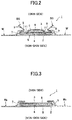
- the front and back ends of the double sheet is bonded to the absorbent body 4 side as illustrated in FIG. 3 . Accordingly, right and left three-dimensional linear gathers BS, BS standing toward the skin side while being sloped outward are formed as illustrated in FIG. 2 .
- a compressed groove 10 that is recessed from a skin contact surface side (an outer surface side of the liquid permeable top sheet 3) toward a non-skin side (a liquid impermeable back sheet 2 side) is formed.
- the compressed groove 10 has front-side lengthwise compressed grooves 11, 11 that are continuously formed, in the approximately longitudinal direction of the sanitary napkin 1, on each side extending from the area including the region corresponding to the body fluid discharge portion H to the area including the region corresponding to the intergluteal cleft.
- the compressed groove 10 also includes back-side lengthwise compressed grooves 12, 12 that are formed at the back away from the front-side lengthwise compressed grooves 11 and are formed on each side of a region corresponding to the back end of the intergluteal cleft.
- the compressed groove 10 also has a front-end crescent-shaped compressed groove 13 that is provided at the front away from the front-side lengthwise compressed grooves 11, 11, crosses the center line in the longitudinal direction of the sanitary napkin 1, and is formed approximately along the width direction of the sanitary napkin 1.
- the compressed groove 10 also has a back-end curved compressed groove 14 that is provided at the back away from the back-side lengthwise compressed grooves 12, 12, crosses the center line in the longitudinal direction of the sanitary napkin 1, and is curved backward.
- a low compression portion 15 and a predetermined high compression portion are formed on the bottom surface of the compressed groove 10.
- the low compression portion 15 is a portion formed such that the depth of the groove is relatively small and density is low.
- the high compression portion is a portion formed such that the depth of the groove is relatively large and density is high.
- the high compression portion in each of the front-side lengthwise compressed grooves 11, includes regularly-arranged high compression portions 16 that are regularly arranged in the longitudinal direction of the compressed groove 11, a large-area high compression portion 17 that is irregularly arranged in the compressed groove 11 and has an area larger than an area of each of the regularly-arranged high compression portions 16, and an auxiliary high compression portion 18 that is arranged at one side (at the front side), in the longitudinal direction of the napkin, of the large-area high compression portion 17 through the low compression portion 15 and that is formed wider than the large-area high compression portion 17 so as to surround the one side, in the longitudinal direction of the napkin, of the large-area high compression portion 17.
- the large-area high compression portion 17 provided at a predetermined position of each of the compressed grooves 11 can serve as a base for transmitting pressure, which is exerted from the both sides in the width direction when the napkin is worn, to the center portion of the absorbent body.
- the center portion of the absorbent body can readily protrude toward the skin side.
- the large-area high compression portion 17 serves as a distinctive feature, thereby improving external appearance of the compressed groove 10.
- pressure such as legs pressure or buttocks pressure is exerted inwardly from the both sides in the width direction.
- the compressed groove 10, provided on the both sides in the width direction transmits such pressure to the center portion of the absorbent body.
- the large-area high compression portion 17 formed in the compressed groove 10 allows pressure, exerted inwardly in the width direction, to be concentrated in the large-area high compression portion 17. Accordingly, the large-area high compression portion 17 can serve as a base for causing the center portion of the absorbent body in the width direction to protrude toward the skin side. By causing the center portion to protrude toward the skin side, the fit of the sanitary napkin can be improved.
- the sanitary napkin 1 is manufactured by what is termed as a vertically moving line method in which the moving direction of the line is taken as the longitudinal direction of the sanitary napkin 1, one side (the front side) in the longitudinal direction of the sanitary napkin 1 is taken as the downstream side in the moving direction of the line during manufacturing, and the other side (the back side) in the longitudinal direction is taken as the upstream side in the moving direction of the line during manufacturing.
- the skin-side surface of the absorbent body 4 being covered by the liquid permeable top sheet 3 is passed between an embossing roll and an anvil roll, and is compressed by projections formed on the embossing roll.
- compression pressure may be dispersed due to the large area, thereby causing a high compression pattern to be unsuccessfully formed.
- compression pressure may be concentrated in a part of the high compression portion, possibly resulting in an embossing defect such as a tear in the top sheet.
- the auxiliary high compression portion 18 is arranged at the downstream side of the large-area high compression portion 17 and is formed wider than the large-area high compression portion 17 so as to surround the downstream side of the large-area high compression portion 17. Therefore, the large-area high compression portion 17 can be pressed while the absorbent body 4 including the top sheet 3 is being temporarily held by the auxiliary high compression portion 18. Accordingly, the large-area high compression portion 17 can be properly formed while also preventing the top sheet 3 from being torn. Thus, embossing defects will not readily occur.
- the large-area high compression portion 17 can be successfully formed without any defect, pressure from the both sides can be readily transmitted to the center portion of the absorbent body and the center portion can readily protrude toward the skin side, allowing the fit of the sanitary napkin to be improved.
- the regularly-arranged high compression portions 16 are portions that are arranged at approximately equal intervals along the compressed groove 11.
- the regularly-arranged high compression portions 16 may be formed so as not to cross the compressed groove 11 in the width direction or may be formed so as to cross the compressed groove 11 in the width direction.
- the regularly-arranged high compression portions 16 are formed in a portion of the compressed groove 11 extending at approximately the same width.
- the large-area high compression portion 17 has a relatively larger area than an area of each of the regularly-arranged high compression portions 16.
- the area of the large-area high compression portion 17 is 2 to 10 times larger, and is preferably 3 to 5 times larger than the area of each of the regularly-arranged high compression portions 16. By setting the area within this range, the large-area high compression portion 17 readily becomes a base for directing pressure inward in the width direction, and external appearance can also be improved.
- the large-area high compression portion 17 is preferably formed in a vastly enlarged portion 19 in which the width of the compressed groove 11 is vastly enlarged.
- the vastly enlarged portion 19 is a portion in which a distance between both side walls of the compressed groove 11 is vastly enlarged, and is formed continuously from the connected compressed groove 11 without being separated from the connected compressed groove 11. Further, the compressed groove 11 can be curved approximately at the same curvature before and after the vastly enlarged portion 19, without being separated or bent at the vastly enlarged portion 19 provided in the middle.
- the regularly-arranged high compression portions 16 are not arranged in the vastly enlarged portion 19.
- the large-area high compression portion 17 and the auxiliary high compression portion 18 are provided in the vastly enlarged portion 19. Namely, the regularly-arranged high compression portions 16 are formed in the part of the compressed groove 11 that is connected to the vastly enlarged portion 19.
- the large-area high compression portion 17 is preferably formed wider than the part of the compressed groove 11 that is connected to the vastly enlarged portion 19 and extends in the front-back direction of the napkin at approximately the same width. Accordingly, the large-area high compression portion 17 readily becomes a base for directing pressure, which is exerted from the both sides in the width direction, inward, and also external appearance can be improved.
- the auxiliary high compression portion 18 is arranged at the downstream side of the large-area high compression portion 17 through the low compression portion 15. Namely, the auxiliary high compression portion 18 is not connected to the large-area high compression portion 17.
- the auxiliary high compression portion 18 is arranged separately from the large-area high compression portion 17. Namely, when a line passing through the large-area high compression portion 17 and extending in the longitudinal direction of the napkin is drawn, the auxiliary high compression portion 18, the low compression portion 15, and the large-area high compression portion 17 are arranged in this order from the downstream side toward the upstream side.
- the auxiliary high compression portion 18, the low compression portion 15, and the large-area high compression portion 17 are pressed in this order.
- the auxiliary high compression portion 18 is formed wider than the large-area high compression portion 17 so as to surround the downstream side of the large-area high compression portion 17. Namely, when the large-area high compression portion 17 is projected onto the downstream side (front side) along the longitudinal direction of the napkin, the projected large-area high compression portion 17 inevitably passes through the auxiliary high compression portion 18.
- the auxiliary high compression portion 18 is preferably formed in such a manner that an outer edge of the upstream side of the auxiliary high compression portion 18 overlaps a part of or the entirety of the large-area high compression portion 17 in the width direction of the napkin. Accordingly, the downstream side of the large-area high compression portion 17 is completely surrounded by the auxiliary high compression portion 18. Thus, an effect obtained by forming the auxiliary high compression portion 18 can be exhibited with more certainty.
- the auxiliary high compression portion 18 is preferably formed into a linear shape or a band shape extending approximately along the width direction of the napkin, so as to surround the downstream side of the large-area high compression portion 17.
- the line width or the band width of the auxiliary high compression portion 18 is preferably smaller than the size (the maximum dimension such as the width dimension or the longitudinal dimension in planar view) of the large-area high compression portion 17. Accordingly, in the embossing processing, the large-area high compression portion 17 can be compressed while being temporarily held by the auxiliary high compression portion 18 having a smaller area than that of the large-area high compression portion 17.
- an auxiliary low compression portion 20 wider than the auxiliary high compression portion 18 is preferably provided at the downstream side of the auxiliary high compression portion 18 so as to surround the downstream side of the auxiliary high compression portion 18. Further, by providing the auxiliary low compression portion 20 at the downstream side of the auxiliary high compression portion 18, while the absorbent body 4 including the top sheet 3 is being temporarily held with pressure lower than that for the auxiliary high compression portion 18, the auxiliary high compression portion 18 and the large-area high compression portion 17 can be pressed. Therefore, embossing defects caused by pressing the auxiliary high compression portion 18 and the large-area high compression portion 17 can be further reduced.
- the auxiliary low compression portion 20 is disposed adjacent to the auxiliary high compression portion 18, and extends from the outer edge of the auxiliary high compression portion 18 to the outer edge of the vastly enlarged portion 19.
- the auxiliary low compression portion 20 is preferably formed in such a manner that an outer edge of the upstream side of the auxiliary low compression portion 20 overlaps a part of or the entirety of the auxiliary high compression portion 18 in the width direction of the napkin. Accordingly, the downstream side of the auxiliary high compression portion 18 is completely surrounded by the auxiliary low compression portion 20. Thus, an effect obtained by forming the auxiliary low compression portion 20 can be exhibited with more certainty.
- the auxiliary low compression portion 20 When a line passing through the large-area high compression portion 17 and extending in the longitudinal direction of the napkin is drawn in the vastly enlarged portion 19 provided with the auxiliary low compression portion 20, the auxiliary low compression portion 20, the auxiliary high compression portion 18, the low compression portion 15, and the large-area high compression portion 17 are arranged in this order from the downstream side toward the upstream side, in such a manner that low compression portions and high compression portions are alternately arranged. Thus, embossing defects can be prevented with more certainty.
- the large-area high compression portion 17 is formed into an approximately star shape in planar view.
- the large-area high compression portion 17 may be formed into a circular shape in planar view as illustrated in FIG. 6 .
- the large-area high compression portion 17 may take various shapes such as an elliptical shape, a polygonal shape, a semicircular shape, and a drop shape, although not illustrated.
- the auxiliary high compression portion 18 may be formed into approximately the same shape in planar view as that of the downstream side of the large-area high compression portion 17.
- the auxiliary high compression portion 18 may be formed into a different shape from that of the downstream side of the large-area high compression portion 17 as illustrated in FIG. 6 (B) .
- the auxiliary high compression portion 18 is preferably formed into a linear shape that widens from the center of the groove width at the downstream side toward the both sides at the upstream side as illustrated in FIG. 6 (B) , so as to prevent embossing defects caused when the auxiliary high compression portion 17 is pressed.
- the large-area high compression portion 17 may be arranged in contact with side walls of the compressed groove 11 or side walls of the vastly enlarged portion 19.
- the large-area high compression portion 17 may be arranged separately from the side walls of the compressed groove 11 and the side walls of the vastly enlarged portion 19 through the low compression portion 15.
- the large-area high compression portion 17 allows pressure exerted from the outside in the width direction to become readily transmitted to the inside.
- the low compression portion 15 because the entire periphery of the large-area high compression portion 17 is surrounded by the low compression portion 15, it becomes possible to further reduce embossing defects while also improving appearance of the large-area high compression portion 17.
- FIG. 7 illustrates exemplary arrangement of the large-area high compression portions 17. Only some of the large-area high compression portions 17 illustrated in FIG. 7 may be arranged, or the large-area high compression portions 17 may be arranged at other positions. To be more specific, the large-area high compression portions 17 may be provided at one intermediate position or at one end position of each of the compressed grooves 11 through 14.
- the large-area high compression portions 17 may be arranged at a plurality of positions both at intermediate and end positions of or only at intermediate positions of each of the compressed grooves 11 through 14 while spaced at larger intervals than arrangement intervals of the regularly-arranged high compression portions 16.
- three large-area high compression portions 17 are arranged in an intermediate portion of each of the front-side lengthwise compressed grooves 11 while being spaced apart from each other in the longitudinal direction of the groove. Also, one large-area high compression portion 17 is arranged at a rear end position of each of the back-side lengthwise compressed grooves 12, one large-area high compression portion 17 is arranged at a rear edge position in the middle of the front-end crescent-shaped compressed groove 13 in the width direction, and one large-area high compression portion 17 is arranged at a middle position of the back-end curved compressed groove 14 in the width direction.
- the large-area high compression portions 17 When the large-area high compression portions 17 are provided at a plurality of positions of a compressed groove, the large-area high compression portions 17 make it easier to transmit pressure to the inside in the width direction. Also, when the large-area high compression portions 17 are provided at an end of compressed grooves, stiffness at the end of the compressed grooves can be prevented from decreasing. Further, when the large-area high compression portions 17 are provided at middle positions of transverse compressed grooves in the width direction, the large-area high compression portions 17 serve as distinctive features, and thus, external appearance of the compressed groove can be improved.
- the front side of the sanitary napkin 1 is regarded as the downstream side and the back side is regarded as the upstream side.
- the back side of the sanitary napkin 1 may be regarded as the downstream side, and the front side may be regarded as the upstream side.
Description
- The present invention generally relates to an absorbent article used for a sanitary napkin, a panty liner, an incontinence pad, or toiletry, and specifically relates to an absorbent article in which a low compression portion and a high compression portion are formed on the bottom surface of a compressed groove that is recessed from a skin contact surface side.
- Conventionally, as absorbent articles such as a panty liner, a sanitary napkin, and an incontinence pad, an absorbent article that includes an absorbent body made of cotton-like pulp and interposed between a liquid impermeable back sheet such as a polyethylene sheet or a polyethylene-sheet-laminated non-woven fabric and a liquid permeable top sheet such as a non-woven fabric or a liquid permeable plastic sheet is known.
- Various improvements have been made to this type of absorbent article. Currently, there is a technique that forms various forms of compressed portions that are concaved from a skin contact surface side toward a non-skin side, such that leakage of body fluids can be prevented and also the absorbent article can be readily deformed along the body shape when the absorbent article is worn.
- For example,
Patent Document 1 below discloses an apparatus for manufacturing an absorbent article. The apparatus includes an embossing roll having projecting portions for forming a compressed groove, and the embossing roll includes tension suppressing portions for suppressing tension that is applied to a top sheet when forming a compressed groove. On the surface of the embossing roll, the suppressing portions are provided around the projecting portions located next to each other in a roll axial direction. The tension suppressing portions are raised from the surface of the embossing roll up to a position lower than low pressure portions of the projecting portions for forming a compressed groove. According to the manufacturing apparatus, because the tension suppressing portions raised lower than the low pressure portions are provided, and a level difference between the tension suppressing portions and the low pressure portions is small, it is possible to reduce tension applied in the roll axial direction of the top sheet. Accordingly, in a manufactured absorbent article, effects of the top sheet and the absorbent body being sufficiently integrally compressed, and of a compressed groove being less likely to be defectively formed, are described. - Further,
Patent Document 2 discloses an absorbent article in which a compressed groove is composed of high-compressed portions and low-compressed portions. The high-compressed portions include approximately transverse high-compressed portions that are formed so as to approximately traverse the compressed groove in the width direction and that are arranged at intervals in a longitudinal direction of the compressed groove, and also include non-transverse high-compressed portions that are formed so as not to traverse the compressed groove and that are arranged at intervals in a region between the approximately transverse high-compressed portions. Further,EP2380541 A1 discloses an absorbent article comprising a pair of right and left compressed grooves formed along the longitudinal direction on the skin-contact surface side of the absorbent article.EP2612635 A1 discloses an absorbent article including a compressed groove formed on the skin contacting surface.WO2015/072502 A1 discloses an absorbent article comprising compression grooves in which a surface sheet and an absorbent that extend in the longitudinal direction are compressed in the thickness direction. -
- [Patent Document 1] Japanese Unexamined Patent Application Publication No.
2016-59540 - [Patent Document 2] Japanese Unexamined Patent Application Publication No.
2010-148706 - However, in the manufacturing apparatus disclosed in
Patent Document 1, the tension suppressing portions press the surface of an absorbent article in the vicinity of front and back sides of a compressed groove. Thus, traces of the tension suppressing portions pressing the surface may be left in the vicinity of the front and back sides of the compressed groove, which may cause the fit and appearance of the absorbent article to decrease. Also, in a region other than the front and back sides of the compressed groove, no countermeasure is taken against tension that causes the top sheet to stretch when pressure is applied. Thus, the compressed groove readily becomes defectively formed or the top sheet readily becomes torn. - In the above absorbent article disclosed in
Patent Document 2, the compressed groove has the approximately transverse high-compressed portions having a relatively larger area and the non-transverse high-compressed portions having a relatively smaller area. When the approximately transverse high-compressed portions having a larger area are formed, large pressure is applied over a wide range, thereby causing a high compression pattern to be unsuccessfully formed and resulting in poor appearance. Alternatively, there is also a problem in that large pressure may be applied only in part, causing the top sheet to be torn. - In view of the above, it is a general object of the present invention to provide an absorbent article in which a low compression portion and a high compression portion are formed on the bottom surface of a compressed groove, and that is capable of preventing the high compression portion from being defectively formed and also preventing the top sheet from being torn.
- In order to solve the above problem, the invention according to
claim 1 provides an absorbent article including an absorbent body interposed between a liquid permeable top sheet and a liquid impermeable back sheet, a low compression portion and a high compression portion being formed on a bottom surface of a compressed groove that is recessed from a skin contact surface side, wherein the high compression portion includes regularly-arranged high compression portions that are regularly arranged in a longitudinal direction of the compressed groove, a large-area high compression portion that is arranged in the compressed groove and has an area larger than an area of each of the regularly-arranged high compression portions, and an auxiliary high compression portion that is arranged at one side, in a longitudinal direction of the absorbent article, of the large-area high compression portion through the low compression portion so as to surround the one side, in the longitudinal direction of the absorbent article, of the large-area high compression portion. - According to the invention of
claim 1, in the aim of exhibiting an effect of causing a center portion of the absorbent body in the width direction to protrude toward a skin side when pressure is exerted from both sides in the width direction when a sanitary napkin is worn, and also in the aim of improving appearance of the compressed groove, the large-area high compression portion having a relatively larger area is arranged at a predetermined position of the compressed groove. The auxiliary high compression portion wider than the large-area high compression portion is arranged at one side, in the longitudinal direction of the absorbent article, of the large-area high compression portion through the low compression portion so as to surround the one side of the large-area high compression portion. The one side in the longitudinal direction of the absorbent article is regarded as a downstream side of the direction in which the line moves when the absorbent article is manufactured. Accordingly, in embossing roll processing, the large-area high compression portion can be pressed while the absorbent body including the top sheet is being temporarily held by the auxiliary high compression portions. Accordingly, it becomes possible to reduce a possibility of the large-area high compression portion being defectively formed and improve appearance of the high compression portion, while also preventing the top sheet from being torn. - The invention according to
claim 2 provides the absorbent article according toclaim 1, wherein the large-area high compression portion is formed in a vastly enlarged portion in which a width of the compressed groove is vastly enlarged. - In the invention according to
claim 2, the large-area high compression portion is arranged in the vastly enlarged portion in which the width of the compressed groove is vastly enlarged. Thus, the vastly enlarged portion serves as a base for transmitting pressure, which is exerted from the both sides in the width direction when the sanitary napkin is worn, to the center portion in the width direction. This allows the center portion of the absorbent body in the width direction to readily protrude toward the skin side, and also allows appearance of the compressed groove to improve. - The invention according to
claim 3 provides the absorbent article according toclaim - In the invention according to
claim 3, the auxiliary high compression portion is disposed at the one side of the large-area high compression portion, and also the auxiliary low compression portion is disposed at the one side, in the longitudinal direction of the absorbent article, of the auxiliary high compression portion. Thus, in the process of pressing the compressed groove, while the absorbent body including the top sheet is being temporarily held by the auxiliary low compression portion at pressure lower than that for the auxiliary high compression portion, the high compression portion can be pressed. Accordingly, it becomes possible to further improve appearance of the high compression portion while also securely preventing the top sheet from being torn. - The invention according to
claim 4 provides the absorbent article according to any one ofclaims 1 to 3, wherein a shape of the auxiliary high compression portion in planar view is approximately same as or different from a shape of the one side, in the longitudinal direction of the absorbent article, of the large-area high compression portion. - In the invention according to
claim 4, by forming the shape of the auxiliary high compression portion in planar view approximately the same as the shape of the one side, in the longitudinal direction of the absorbent article, of the large-area high compression portion, an effect of temporarily holding down the top sheet can be improved. Also, in order to suppress wrinkles due to the auxiliary high compression portion being formed, the auxiliary high compression portion may have a different shape from the one side of the large-area high compression portion. - The invention according to
claim 5 provides the absorbent article according to any one ofclaims 1 to 4, wherein the large-area high compression portion is arranged in contact with side walls of the compressed groove, or is arranged separately from the side walls of the compressed groove through the low compression portion. - In the invention according to
claim 5, the other side, in the longitudinal direction of the absorbent article, of the large-area high compression portion may be arranged in contact with the side walls of the compressed groove or may be arranged separately from the side walls of the compressed groove. - The invention according to
claim 6 provides the absorbent article according to any one ofclaims 1 to 5, wherein the large-area high compression portion includes one or more large-area high compression portions arranged at one intermediate position or at one end position of the compressed groove, or arranged both at intermediate and end positions of or only at intermediate positions of the compressed groove while spaced at larger intervals than arrangement intervals of the regularly-arranged high compression portions. - In the invention according to
claim 6, with regard to an arrangement pattern, one or more large-area high compression portions may be arranged in the compressed groove. The arrangement pattern may be determined as desired, depending on the function or the size of the absorbent article. - According to the invention as described above, it becomes possible to prevent a high compression portion from being defectively formed and also prevent a top sheet from being torn.
-
-
FIG. 1 is a partially expanded cutaway view of asanitary napkin 1; -
FIG. 2 is a cross-sectional view taken along a line II-II ofFIG. 1 ; -
FIG. 3 is a cross-sectional view taken along a line III-III ofFIG. 1 ; -
FIG. 4 is an enlarged view of a main portion ofFIG. 1 ; -
FIG. 5 is an enlarged view of a front-side lengthwise compressedgroove 11; -
FIG. 6 is an enlarged view of a front-side lengthwise compressedgroove 11 according to a variation; and -
FIG. 7 is an expanded view of asanitary napkin 1 according to the variation. - In the following, embodiments of the present invention are described below with reference to the accompanying drawings.
- As illustrated in
FIGS. 1 through 3 , asanitary napkin 1 according to the present invention includes: a liquidimpermeable back sheet 2 formed of a polyethylene sheet, for example; a liquid permeabletop sheet 3 that allows menstrual blood, vaginal discharge, and the like (hereinafter also collectively referred to as body fluids) to quickly pass through; anabsorbent body 4 interposed between thesheets non-woven fabric 7 provided over the approximately entire length of each side of a skin contact surface along a longitudinal direction. At front and back end portions of theabsorbent body 4, outer end portions of the liquidimpermeable back sheet 2 and the liquid permeabletop sheet 3 are bonded to each other with an adhesive such as a hot-melt adhesive or with an adhesive means such as a heat seal or an ultrasonic seal. Furthermore, at each side of theabsorbent body 4, the liquidimpermeable back sheet 2 and the sidenon-woven fabric 7 that laterally extends longer than theabsorbent body 4 are bonded to each other with an adhesive such as a hot-melt adhesive or with an adhesive means such as a heat seal and an ultrasonic seal. As a result, flaps without the absorbent body are formed. In the illustrated example, in order to maintain the shape of theabsorbent body 4 and to improve diffusivity thereof, theabsorbent body 4 is surrounded by an encapsulatingsheet 5 made of a crepe paper sheet or a non-woven fabric; however, the encapsulatingsheet 5 is not necessarily provided. Although not illustrated, a second sheet formed of a hydrophilic non-woven fabric and having approximately the same shape as the liquid permeabletop sheet 3 may be disposed facing a non-skin side of the liquid permeabletop sheet 3. - In the following, the structure of the
sanitary napkin 1 will be described in more detail. The liquidimpermeable back sheet 2 uses a sheet material such as polyethylene having at least a water shielding property. In addition, in terms of stuffiness prevention, a material having moisture permeability is preferably used. As such a water shielding and permeable sheet material, a microporous sheet is preferably used. The microporous sheet is obtained by forming a sheet by melting and kneading inorganic filler with olefin resin such as polyethylene and polypropylene, and subsequently stretching the sheet in one axial direction or two axial directions. On a non-skin side (an outer surface) of the liquidimpermeable back sheet 2, one or more adhesive layers (not illustrated) are formed along the longitudinal direction of the napkin such that thesanitary napkin 1 is fixed to underwear when worn. As the liquidimpermeable back sheet 2, a polyethylene laminate non-woven fabric having a plastic film and a non-woven fabric layered on each other may be used. - Next, as the liquid permeable
top sheet 3, a perforated or an imperforated non-woven fabric, a porous plastic sheet, or the like is preferably used. Examples of a material fiber forming the non-woven fabric include synthetic fibers such as an olefin-based synthetic fiber such as polyethylene or polypropylene, a polyester-based synthetic fiber, and a polyamide-based synthetic fiber, regenerated fibers such as rayon and cuprammonium rayon, and natural fibers such as cotton. Further, as the liquid permeabletop sheet 3, a non-woven fabric obtained by applying an appropriate processing method such as a spunlace method, a spunbond method, a thermal bond method, a melt blown method, or a needle punch method to any of the above-described material fibers may be used. Among these processing methods, the spunlace method is superior in terms of flexibility, the spunbond method is superior in terms of drape properties, and the thermal bond method is superior in terms of bulkiness and compression restorability. When a number of through-holes are formed on the liquid permeabletop sheet 3, body fluids can become quickly absorbed, providing a wearer with an excellent dry touch. Although either a long fiber or a short fiber may be used as the non-woven fabric, it is preferable to use a short fiber in order to provide texture of towel cloth. Further, in order to facilitate an embossing process, an olefin-based fiber such as polyethylene or polypropylene having a relatively low melting point may be used. Further, a composite fiber such as a core-in-sheath fiber having a high-melting-point fiber as a core and a low-melting-point fiber as a sheath, a side-by-side fiber, or a split fiber may be preferably used. - The
absorbent body 4 interposed between the liquidimpermeable back sheet 2 and the liquid permeabletop sheet 3 is formed of, for example, cotton-like pulp and a water-absorptive polymer. The water-absorptive polymer is mixed, for example, as a granular powder, into the pulp that forms the absorbent body. Examples of the pulp include chemical pulp made from wood, cellulose fibers such as dissolving pulp, and synthetic cellulose fibers such as rayon and acetate. In terms of function and price, softwood pulp with a long fiber length is more preferably used than hardwood pulp. - Further, a synthetic fiber may be mixed into the
absorbent body 4. Examples of the synthetic fiber that may be used include polyolefin-based fibers such as polyethylene and polypropylene, polyester-based fibers such as polyethylene terephthalate and polybutylene terephthalate, polyamide-based fibers such as nylon, and a copolymer thereof. Also, a mixture of two types of the above-described fibers may be used. Further, a composite fiber such as a core-in-sheath fiber having a high-melting-point fiber as a core and a low-melting-point fiber as a sheath, a side-by-side fiber, or a split fiber may be used. Also, a mixture of two types of the above-described fibers may be used. Further, a composite fiber such as a core-in-sheath fiber having a high-melting-point fiber as a core and a low-melting-point fiber as a sheath, a side-by-side fiber, or a split fiber may be used. In order to have hydrophilicity with body fluids, the synthetic fiber preferably undergoes surface treatment by using, for example, a hydrophilizing agent when a hydrophobic fiber is used. - As illustrated in
FIG. 1 andFIG. 2 , a raisedcenter portion 6 having an increased thickness toward the skin side is preferably provided in an area including a region corresponding to a body fluid discharge portion H of theabsorbent body 4. The raisedcenter portion 6 is located at a skin-side surface of theabsorbent body 4, and is provided at a center portion in the width direction of theabsorbent body 4. The raisedcenter portion 6 has a width dimension and a longitudinal dimension smaller relative to those of theabsorbent body 4. If the raisedcenter portion 6 is too thick, stiffness increases and the raisedcenter portion 6 does not well fit the body. If the raisedcenter portion 6 is too thin, the raisedcenter portion 6 does not sufficiently make close contact with the body fluid discharge portion H. Accordingly, the thickness of the raisedcenter portion 6 is 3 to 25 mm, and is preferably 5 to 18 mm. - The raised
center portion 6 is provided in an area including the region corresponding to at least the body fluid discharge portion H of the wearer. The raisedcenter portion 6 may be formed into an elongated shape that continues from the area including the region corresponding to the body fluid discharge portion H to an area including a region corresponding to the intergluteal cleft of the wearer. Alternatively, the raisedcenter portion 6 may be disposed only in the area including the region corresponding to the body fluid discharge portion H, and is not necessarily provided in the backward area including the region corresponding to the intergluteal cleft. - When the raised
center portion 6 is formed into the elongated shape, which continues from the area including the region corresponding to the body fluid discharge portion H to the area including the region corresponding to the intergluteal cleft, a narrow width portion, whose outline on each side is curved inward in the width direction, is preferably provided at the back of the region corresponding to the body fluid discharge portion H. By providing the narrow width portion, the raisedcenter portion 6 tends to fit a small recess or projection formed on the skin surface extending from the back end of the body fluid discharge portion H to the start position of the intergluteal cleft of the wearer, thereby enhancing close contact with the skin surface. - The raised
center portion 6 includes at least a pulp fiber and a synthetic fiber. The pulp fiber and synthetic fiber are mixed at a ratio ranging from 80:20 to 20:80 in terms of weight, and are preferably mixed at a ratio ranging from 40:60 to 60:40 in terms of weight. Further, the raisedcenter portion 6 may also include a water-absorptive polymer. Examples of the water-absorptive polymer include a polyacrylate cross-linked product, a self-crosslinked polyacrylic acid salt, an acrylic acid ester-vinyl acetate copolymer cross-linked saponified product, an isobutylene-maleic anhydride copolymer cross-linked product, a polysulfone salt cross-linked product, and a product obtained by partially cross-linking a water-swellable polymer such as polyethylene oxide or polyacrylamide. Among them, an acrylic acid or an acrylic acid salt, which is excellent in absorbed amount and water absorption rate, is preferable. For such a water-absorptive polymer having the above-described water absorption performance, it is possible to adjust the absorption power and the water absorption rate by adjusting the cross-linking density and the cross-linking density gradient in a production process. Because the raisedcenter portion 6 promotes permeation into theabsorbent body 4, what is known as gel blocking occurs when the content of the water-absorptive polymer is large. Thus, the content of the water-absorptive polymer in terms of weight is preferably 1% to 10% of the total weight of the pulp fiber and the synthetic fiber. When the content of the water-absorptive polymer exceeds 50%, the fibers become not entangled, decreasing the strength of the sheet and causing the sheet to be ripped or cracked. Thus, the water-absorptive polymer content of more than 50% is not desired. - As illustrated in the cross-sectional views of
FIG. 2 and FIG. 3 , a width dimension of the liquid permeabletop sheet 3 is slightly larger than a width of theabsorbent body 4 so as to cover theabsorbent body 4. The sidenon-woven fabric 7, formed of a different material from the liquid permeabletop sheet 3, is provided outside the liquid permeabletop sheet 3. To be more specific, the sidenon-woven fabric 7 is formed of a non-woven fabric material to which appropriate water-repellency treatment or hydrophilic treatment is applied, depending on the purpose such as preventing menstrual blood or vaginal discharge from permeating or enhancing texture. As the sidenon-woven fabric 7, a sheet that uses a synthetic fiber or a regenerated fiber as a material and is formed by an appropriate processing method may be used. Preferably, in order to prevent stuffiness while eliminating friction with the skin, a non-woven fabric having air permeability with a reduced basis weight may be used as the sidenon-woven fabric 7. Preferably, in order to prevent stuffiness while eliminating friction with the skin, a non-woven fabric having air permeability with a reduced basis weight may be used as the sidenon-woven fabric 7. To be more specific, a non-woven fabric with a basis weight of 13 to 23 g/m2 is desirably used. Further, in order to securely prevent body fluids from permeating, a water-repellent non-woven fabric coated with a silicon-based, a paraffin-based, or an alkyl-chromic-chloride-based water-repellent agent is preferably used. - As illustrated in
FIG. 2 and FIG. 3 , on each outer side of the sanitary napkin relative to the middle portion in the width direction, the sidenon-woven fabric 7 is bonded from an inward position to an outer edge of the liquidimpermeable back sheet 2 with an adhesive such as a hot-melt adhesive. The layered sheet portions of the liquidimpermeable back sheet 2 and each of theside non-woven fabrics 7 form flaps on both sides of theabsorbent body 4, without theabsorbent body 4 being interposed. The flaps may include a pair of right and left wing-shaped flaps W, W at positions alongside the body fluid discharge region H of theabsorbent body 4, and may also include hip-holding flaps WB, WB on the buttocks side (back side) relative to the wing-shaped flaps W, W. Outer surfaces of the wing-shaped flaps W, W and the hip-holding flaps WB, WB have adhesive layers (not illustrated). When the sanitary napkin is attached to underwear, the wing-shaped flaps W, W are folded back at positions of fold-back lines RL so as to be fixed to a crotch portion of the underwear, and also the hip-holding flaps WB, WB are fixed to an inner surface of the underwear. - An inner side of the side
non-woven fabric 7 is folded back to be almost two-fold, and one or a plurality of (in the illustrated example, three) threadlike elastic expansion andcontraction members contraction members absorbent body 4 side as illustrated inFIG. 3 . Accordingly, right and left three-dimensional linear gathers BS, BS standing toward the skin side while being sloped outward are formed as illustrated inFIG. 2 . - In the
sanitary napkin 1, acompressed groove 10 that is recessed from a skin contact surface side (an outer surface side of the liquid permeable top sheet 3) toward a non-skin side (a liquidimpermeable back sheet 2 side) is formed. As illustrated inFIG. 1 , thecompressed groove 10 has front-side lengthwise compressedgrooves sanitary napkin 1, on each side extending from the area including the region corresponding to the body fluid discharge portion H to the area including the region corresponding to the intergluteal cleft. Thecompressed groove 10 also includes back-side lengthwise compressedgrooves grooves 11 and are formed on each side of a region corresponding to the back end of the intergluteal cleft. Thecompressed groove 10 also has a front-end crescent-shapedcompressed groove 13 that is provided at the front away from the front-side lengthwise compressedgrooves sanitary napkin 1, and is formed approximately along the width direction of thesanitary napkin 1. Thecompressed groove 10 also has a back-end curved compressedgroove 14 that is provided at the back away from the back-side lengthwise compressedgrooves sanitary napkin 1, and is curved backward. - A
low compression portion 15 and a predetermined high compression portion are formed on the bottom surface of thecompressed groove 10. Thelow compression portion 15 is a portion formed such that the depth of the groove is relatively small and density is low. The high compression portion is a portion formed such that the depth of the groove is relatively large and density is high. - In the
sanitary napkin 1 according to the embodiment ofFIG. 1 , in each of the front-side lengthwise compressedgrooves 11, the high compression portion includes regularly-arrangedhigh compression portions 16 that are regularly arranged in the longitudinal direction of thecompressed groove 11, a large-areahigh compression portion 17 that is irregularly arranged in thecompressed groove 11 and has an area larger than an area of each of the regularly-arrangedhigh compression portions 16, and an auxiliaryhigh compression portion 18 that is arranged at one side (at the front side), in the longitudinal direction of the napkin, of the large-areahigh compression portion 17 through thelow compression portion 15 and that is formed wider than the large-areahigh compression portion 17 so as to surround the one side, in the longitudinal direction of the napkin, of the large-areahigh compression portion 17. - In the present
sanitary napkin 1, the large-areahigh compression portion 17 provided at a predetermined position of each of thecompressed grooves 11 can serve as a base for transmitting pressure, which is exerted from the both sides in the width direction when the napkin is worn, to the center portion of the absorbent body. As a result, the center portion of the absorbent body can readily protrude toward the skin side. Also, the large-areahigh compression portion 17 serves as a distinctive feature, thereby improving external appearance of thecompressed groove 10. To be more specific, when thesanitary napkin 1 is worn, pressure such as legs pressure or buttocks pressure is exerted inwardly from the both sides in the width direction. Thecompressed groove 10, provided on the both sides in the width direction, transmits such pressure to the center portion of the absorbent body. At this time, the large-areahigh compression portion 17 formed in thecompressed groove 10 allows pressure, exerted inwardly in the width direction, to be concentrated in the large-areahigh compression portion 17. Accordingly, the large-areahigh compression portion 17 can serve as a base for causing the center portion of the absorbent body in the width direction to protrude toward the skin side. By causing the center portion to protrude toward the skin side, the fit of the sanitary napkin can be improved. - The
sanitary napkin 1 is manufactured by what is termed as a vertically moving line method in which the moving direction of the line is taken as the longitudinal direction of thesanitary napkin 1, one side (the front side) in the longitudinal direction of thesanitary napkin 1 is taken as the downstream side in the moving direction of the line during manufacturing, and the other side (the back side) in the longitudinal direction is taken as the upstream side in the moving direction of the line during manufacturing. - In order to form the
compressed groove 10, the skin-side surface of theabsorbent body 4 being covered by the liquid permeabletop sheet 3 is passed between an embossing roll and an anvil roll, and is compressed by projections formed on the embossing roll. - At this time, when forming a high compression portion having a relatively large area, compression pressure may be dispersed due to the large area, thereby causing a high compression pattern to be unsuccessfully formed. Conversely, compression pressure may be concentrated in a part of the high compression portion, possibly resulting in an embossing defect such as a tear in the top sheet.
- In light of the above, in the
sanitary napkin 1, the auxiliaryhigh compression portion 18 is arranged at the downstream side of the large-areahigh compression portion 17 and is formed wider than the large-areahigh compression portion 17 so as to surround the downstream side of the large-areahigh compression portion 17. Therefore, the large-areahigh compression portion 17 can be pressed while theabsorbent body 4 including thetop sheet 3 is being temporarily held by the auxiliaryhigh compression portion 18. Accordingly, the large-areahigh compression portion 17 can be properly formed while also preventing thetop sheet 3 from being torn. Thus, embossing defects will not readily occur. Further, because the large-areahigh compression portion 17 can be successfully formed without any defect, pressure from the both sides can be readily transmitted to the center portion of the absorbent body and the center portion can readily protrude toward the skin side, allowing the fit of the sanitary napkin to be improved. - The regularly-arranged
high compression portions 16 are portions that are arranged at approximately equal intervals along thecompressed groove 11. The regularly-arrangedhigh compression portions 16 may be formed so as not to cross thecompressed groove 11 in the width direction or may be formed so as to cross thecompressed groove 11 in the width direction. The regularly-arrangedhigh compression portions 16 are formed in a portion of thecompressed groove 11 extending at approximately the same width. - The large-area
high compression portion 17 has a relatively larger area than an area of each of the regularly-arrangedhigh compression portions 16. The area of the large-areahigh compression portion 17 is 2 to 10 times larger, and is preferably 3 to 5 times larger than the area of each of the regularly-arrangedhigh compression portions 16. By setting the area within this range, the large-areahigh compression portion 17 readily becomes a base for directing pressure inward in the width direction, and external appearance can also be improved. - Referring to
FIG. 5 , the large-areahigh compression portion 17 is preferably formed in a vastlyenlarged portion 19 in which the width of thecompressed groove 11 is vastly enlarged. The vastlyenlarged portion 19 is a portion in which a distance between both side walls of thecompressed groove 11 is vastly enlarged, and is formed continuously from the connected compressedgroove 11 without being separated from the connected compressedgroove 11. Further, thecompressed groove 11 can be curved approximately at the same curvature before and after the vastlyenlarged portion 19, without being separated or bent at the vastlyenlarged portion 19 provided in the middle. - The regularly-arranged
high compression portions 16 are not arranged in the vastlyenlarged portion 19. The large-areahigh compression portion 17 and the auxiliaryhigh compression portion 18 are provided in the vastlyenlarged portion 19. Namely, the regularly-arrangedhigh compression portions 16 are formed in the part of thecompressed groove 11 that is connected to the vastlyenlarged portion 19. - The large-area
high compression portion 17 is preferably formed wider than the part of thecompressed groove 11 that is connected to the vastlyenlarged portion 19 and extends in the front-back direction of the napkin at approximately the same width. Accordingly, the large-areahigh compression portion 17 readily becomes a base for directing pressure, which is exerted from the both sides in the width direction, inward, and also external appearance can be improved. - The auxiliary
high compression portion 18 is arranged at the downstream side of the large-areahigh compression portion 17 through thelow compression portion 15. Namely, the auxiliaryhigh compression portion 18 is not connected to the large-areahigh compression portion 17. By providing thelow compression portion 15 between the auxiliaryhigh compression portion 18 and the large-areahigh compression portion 17, the auxiliaryhigh compression portion 18 is arranged separately from the large-areahigh compression portion 17. Namely, when a line passing through the large-areahigh compression portion 17 and extending in the longitudinal direction of the napkin is drawn, the auxiliaryhigh compression portion 18, thelow compression portion 15, and the large-areahigh compression portion 17 are arranged in this order from the downstream side toward the upstream side. Thus, when thesanitary napkin 1 is pressed by the embossing roll in the manufacturing process, the auxiliaryhigh compression portion 18, thelow compression portion 15, and the large-areahigh compression portion 17 are pressed in this order. - The auxiliary
high compression portion 18 is formed wider than the large-areahigh compression portion 17 so as to surround the downstream side of the large-areahigh compression portion 17. Namely, when the large-areahigh compression portion 17 is projected onto the downstream side (front side) along the longitudinal direction of the napkin, the projected large-areahigh compression portion 17 inevitably passes through the auxiliaryhigh compression portion 18. - The auxiliary
high compression portion 18 is preferably formed in such a manner that an outer edge of the upstream side of the auxiliaryhigh compression portion 18 overlaps a part of or the entirety of the large-areahigh compression portion 17 in the width direction of the napkin. Accordingly, the downstream side of the large-areahigh compression portion 17 is completely surrounded by the auxiliaryhigh compression portion 18. Thus, an effect obtained by forming the auxiliaryhigh compression portion 18 can be exhibited with more certainty. - The auxiliary
high compression portion 18 is preferably formed into a linear shape or a band shape extending approximately along the width direction of the napkin, so as to surround the downstream side of the large-areahigh compression portion 17. The line width or the band width of the auxiliaryhigh compression portion 18 is preferably smaller than the size (the maximum dimension such as the width dimension or the longitudinal dimension in planar view) of the large-areahigh compression portion 17. Accordingly, in the embossing processing, the large-areahigh compression portion 17 can be compressed while being temporarily held by the auxiliaryhigh compression portion 18 having a smaller area than that of the large-areahigh compression portion 17. - As illustrated in
FIG. 5 , in the vastlyenlarged portion 19, an auxiliarylow compression portion 20 wider than the auxiliaryhigh compression portion 18 is preferably provided at the downstream side of the auxiliaryhigh compression portion 18 so as to surround the downstream side of the auxiliaryhigh compression portion 18. Further, by providing the auxiliarylow compression portion 20 at the downstream side of the auxiliaryhigh compression portion 18, while theabsorbent body 4 including thetop sheet 3 is being temporarily held with pressure lower than that for the auxiliaryhigh compression portion 18, the auxiliaryhigh compression portion 18 and the large-areahigh compression portion 17 can be pressed. Therefore, embossing defects caused by pressing the auxiliaryhigh compression portion 18 and the large-areahigh compression portion 17 can be further reduced. The auxiliarylow compression portion 20 is disposed adjacent to the auxiliaryhigh compression portion 18, and extends from the outer edge of the auxiliaryhigh compression portion 18 to the outer edge of the vastlyenlarged portion 19. The auxiliarylow compression portion 20 is preferably formed in such a manner that an outer edge of the upstream side of the auxiliarylow compression portion 20 overlaps a part of or the entirety of the auxiliaryhigh compression portion 18 in the width direction of the napkin. Accordingly, the downstream side of the auxiliaryhigh compression portion 18 is completely surrounded by the auxiliarylow compression portion 20. Thus, an effect obtained by forming the auxiliarylow compression portion 20 can be exhibited with more certainty. When a line passing through the large-areahigh compression portion 17 and extending in the longitudinal direction of the napkin is drawn in the vastlyenlarged portion 19 provided with the auxiliarylow compression portion 20, the auxiliarylow compression portion 20, the auxiliaryhigh compression portion 18, thelow compression portion 15, and the large-areahigh compression portion 17 are arranged in this order from the downstream side toward the upstream side, in such a manner that low compression portions and high compression portions are alternately arranged. Thus, embossing defects can be prevented with more certainty. - In the example illustrated in
FIG. 5 , the large-areahigh compression portion 17 is formed into an approximately star shape in planar view. However, the large-areahigh compression portion 17 may be formed into a circular shape in planar view as illustrated inFIG. 6 . Alternatively, the large-areahigh compression portion 17 may take various shapes such as an elliptical shape, a polygonal shape, a semicircular shape, and a drop shape, although not illustrated. - As illustrated in
FIG. 5 and FIG. 6 (A) , the auxiliaryhigh compression portion 18 may be formed into approximately the same shape in planar view as that of the downstream side of the large-areahigh compression portion 17. Alternatively, the auxiliaryhigh compression portion 18 may be formed into a different shape from that of the downstream side of the large-areahigh compression portion 17 as illustrated inFIG. 6 (B) . When formed into a different shape, the auxiliaryhigh compression portion 18 is preferably formed into a linear shape that widens from the center of the groove width at the downstream side toward the both sides at the upstream side as illustrated inFIG. 6 (B) , so as to prevent embossing defects caused when the auxiliaryhigh compression portion 17 is pressed. - Also, as illustrated in
FIG. 5 and FIG. 6 (B) , the large-areahigh compression portion 17 may be arranged in contact with side walls of thecompressed groove 11 or side walls of the vastlyenlarged portion 19. Alternatively, as illustrated inFIG. 6 (A) , the large-areahigh compression portion 17 may be arranged separately from the side walls of thecompressed groove 11 and the side walls of the vastlyenlarged portion 19 through thelow compression portion 15. In the former case, the large-areahigh compression portion 17 allows pressure exerted from the outside in the width direction to become readily transmitted to the inside. In the latter case, because the entire periphery of the large-areahigh compression portion 17 is surrounded by thelow compression portion 15, it becomes possible to further reduce embossing defects while also improving appearance of the large-areahigh compression portion 17. - In the
sanitary napkin 1 illustrated inFIG. 1 , only one large-areahigh compression portion 17 is provided at an intermediate position of each of the front-side lengthwise compressedgrooves 11. However, as illustrated inFIG. 7 , a plurality of large-areahigh compression portions 17 may be provided at any positions of thecompressed grooves 11 through 14.FIG. 7 illustrates exemplary arrangement of the large-areahigh compression portions 17. Only some of the large-areahigh compression portions 17 illustrated inFIG. 7 may be arranged, or the large-areahigh compression portions 17 may be arranged at other positions. To be more specific, the large-areahigh compression portions 17 may be provided at one intermediate position or at one end position of each of thecompressed grooves 11 through 14. Alternatively, the large-areahigh compression portions 17 may be arranged at a plurality of positions both at intermediate and end positions of or only at intermediate positions of each of thecompressed grooves 11 through 14 while spaced at larger intervals than arrangement intervals of the regularly-arrangedhigh compression portions 16. - In the example of
FIG. 7 , three large-areahigh compression portions 17 are arranged in an intermediate portion of each of the front-side lengthwise compressedgrooves 11 while being spaced apart from each other in the longitudinal direction of the groove. Also, one large-areahigh compression portion 17 is arranged at a rear end position of each of the back-side lengthwise compressedgrooves 12, one large-areahigh compression portion 17 is arranged at a rear edge position in the middle of the front-end crescent-shapedcompressed groove 13 in the width direction, and one large-areahigh compression portion 17 is arranged at a middle position of the back-end curved compressedgroove 14 in the width direction. When the large-areahigh compression portions 17 are provided at a plurality of positions of a compressed groove, the large-areahigh compression portions 17 make it easier to transmit pressure to the inside in the width direction. Also, when the large-areahigh compression portions 17 are provided at an end of compressed grooves, stiffness at the end of the compressed grooves can be prevented from decreasing. Further, when the large-areahigh compression portions 17 are provided at middle positions of transverse compressed grooves in the width direction, the large-areahigh compression portions 17 serve as distinctive features, and thus, external appearance of the compressed groove can be improved. - In the above-described embodiment, the front side of the
sanitary napkin 1 is regarded as the downstream side and the back side is regarded as the upstream side. Conversely, the back side of thesanitary napkin 1 may be regarded as the downstream side, and the front side may be regarded as the upstream side. -
- 1
- sanitary napkin
- 2
- liquid impermeable back sheet
- 3
- liquid permeable top sheet
- 4
- absorbent body
- 5
- encapsulating sheet
- 6
- raised center portion
- 7
- side non-woven fabric
- 9
- threadlike elastic expansion and contraction member
- 10
- compressed groove
- 11
- front-side lengthwise compressed groove
- 12
- back-side lengthwise compressed groove
- 13
- front-end crescent-shaped compressed groove
- 14
- back-end curved compressed groove
- 15
- low compression portion
- 16
- regularly-arranged high compression portion
- 17
- large-area high compression portion
- 18
- auxiliary high compression portion
- 19
- vastly enlarged portion
- 20
- auxiliary low compression portion
Claims (8)
- An absorbent article (1) comprising,
an absorbent body (4) interposed between a liquid permeable top sheet (3) and a liquid impermeable back sheet (2), a low compression portion (15) and a high compression portion being formed on a bottom surface of a compressed groove (10) that is recessed from a skin contact surface side,
wherein the high compression portion includes regularly-arranged high compression portions (16) that are regularly arranged in a longitudinal direction of the compressed groove (10), a large-area high compression portion (17) that is arranged in the compressed groove (10) and has an area larger than an area of each of the regularly-arranged high compression portions (16), and an auxiliary high compression portion (18) that is arranged at one side, in a longitudinal direction of the absorbent article (1), of the large-area high compression portion (17) through the low compression portion (15) so as to surround the one side, in the longitudinal direction of the absorbent article (1), of the large-area high compression portion (17). - The absorbent article (1) according to claim 1, wherein the large-area high compression portion (17) is formed in an enlarged portion (19) in which a width of the compressed groove (10) is enlarged.
- The absorbent article (1) according to claim 1 or 2, wherein an auxiliary low compression portion (20) that is wider than the auxiliary high compression portion (18) is disposed so as to surround one side, in the longitudinal direction of the absorbent article (1), of the auxiliary high compression portion (18).
- The absorbent article (1) according to any one of claims 1 to 3, wherein a shape of the auxiliary high compression portion (18) in planar view is same as or different from a shape of the one side, in the longitudinal direction of the absorbent article (1), of the large-area high compression portion (17).
- The absorbent article (1) according to any one of claims 1 to 4, wherein the large-area high compression portion (17) is arranged in contact with side walls of the compressed groove (10), or is arranged separately from the side walls of the compressed groove (10) through the low compression portion (15).
- The absorbent article (1) according to any one of claims 1 to 5, wherein the large-area high compression portion (17) includes one or more large-area high compression portions (17) arranged at one intermediate position or at one end position of the compressed groove (10), or arranged both at intermediate and end positions of or only at intermediate positions of the compressed groove (10) while spaced at larger intervals than arrangement intervals of the regularly-arranged high compression portions (16).
- A method for manufacturing the absorbent article (1) according to any one of claims 1 to 6, by a vertically moving line method, wherein
a moving direction of a manufacturing line is taken as the longitudinal direction of the absorbent article (1),
a front side in the longitudinal direction of the absorbent article (1) is taken as a downstream side in the moving direction of the manufacturing line, and
a back side in the longitudinal direction of the absorbent article (1) is taken as an upstream side in the moving direction of the manufacturing line. - The method according to claim 7, wherein the auxiliary high compression portion (18) is arranged separately from the large-area high compression portion (17) by pressing the auxiliary high compression portion (18), the low compression portion (15), and the large-area high compression portion (17) in this order by an embossing roll.
Applications Claiming Priority (2)
| Application Number | Priority Date | Filing Date | Title |
|---|---|---|---|
| JP2016118172A JP6207675B1 (en) | 2016-06-14 | 2016-06-14 | Absorbent articles |
| PCT/JP2017/021592 WO2017217356A1 (en) | 2016-06-14 | 2017-06-12 | Absorbent article |
Publications (3)
| Publication Number | Publication Date |
|---|---|
| EP3470036A4 EP3470036A4 (en) | 2019-04-17 |
| EP3470036A1 EP3470036A1 (en) | 2019-04-17 |
| EP3470036B1 true EP3470036B1 (en) | 2021-02-17 |
Family
ID=59997668
Family Applications (1)
| Application Number | Title | Priority Date | Filing Date |
|---|---|---|---|
| EP17813252.8A Active EP3470036B1 (en) | 2016-06-14 | 2017-06-12 | Absorbent article |
Country Status (5)
| Country | Link |
|---|---|
| US (1) | US11510828B2 (en) |
| EP (1) | EP3470036B1 (en) |
| JP (1) | JP6207675B1 (en) |
| CN (1) | CN109152681B (en) |
| WO (1) | WO2017217356A1 (en) |
Families Citing this family (7)
| Publication number | Priority date | Publication date | Assignee | Title |
|---|---|---|---|---|
| MX2019014683A (en) | 2017-06-09 | 2020-02-07 | Essity Hygiene & Health Ab | Disposable hygiene article with improved fit. |
| US11123239B2 (en) | 2017-06-09 | 2021-09-21 | Essity Hygiene And Health Aktiebolag | Disposable hygiene article with improved fit |
| MX2019014718A (en) | 2017-06-09 | 2020-02-07 | Essity Hygiene & Health Ab | Disposable hygiene article with improved fit. |
| JP6965729B2 (en) * | 2017-12-21 | 2021-11-10 | 王子ホールディングス株式会社 | Absorbent article |
| WO2020117109A1 (en) | 2018-12-05 | 2020-06-11 | Essity Hygiene And Health Aktiebolag | Disposable hygiene article with improved fit |
| BR112021007853B1 (en) * | 2018-12-05 | 2024-01-02 | Essity Hygiene And Health Aktiebolag | DISPOSABLE HYGIENE ARTICLE AND METHOD FOR MANUFACTURING THE DISPOSABLE ARTICLE |
| EP3890675B1 (en) | 2018-12-05 | 2023-11-08 | Essity Hygiene and Health Aktiebolag | Disposable hygiene article with improved fit |
Family Cites Families (10)
| Publication number | Priority date | Publication date | Assignee | Title |
|---|---|---|---|---|
| JP4246446B2 (en) * | 2002-06-07 | 2009-04-02 | ユニ・チャーム株式会社 | Absorbent articles |
| JP5317685B2 (en) | 2008-12-25 | 2013-10-16 | ユニ・チャーム株式会社 | Absorbent articles |
| JP5294837B2 (en) * | 2008-12-25 | 2013-09-18 | ユニ・チャーム株式会社 | Absorbent articles |
| EA201201276A1 (en) * | 2010-04-06 | 2013-04-30 | Юничарм Корпорейшн | ABSORBING PRODUCT AND METHOD OF MANUFACTURING AN ABSORBING PRODUCT |
| JP5623828B2 (en) * | 2010-08-31 | 2014-11-12 | 大王製紙株式会社 | Absorbent articles |
| JP5755856B2 (en) | 2010-09-01 | 2015-07-29 | ユニ・チャーム株式会社 | Absorbent articles |
| JP5727246B2 (en) * | 2011-01-31 | 2015-06-03 | 大王製紙株式会社 | Absorbent articles |
| JP6219573B2 (en) * | 2013-01-31 | 2017-10-25 | ユニ・チャーム株式会社 | Absorbent articles |
| WO2015072502A1 (en) | 2013-11-14 | 2015-05-21 | ユニ・チャーム株式会社 | Absorbent article |
| JP6359393B2 (en) | 2014-09-17 | 2018-07-18 | 花王株式会社 | Absorbent article manufacturing equipment |
-
2016
- 2016-06-14 JP JP2016118172A patent/JP6207675B1/en active Active
-
2017
- 2017-06-12 US US16/305,217 patent/US11510828B2/en active Active
- 2017-06-12 CN CN201780031284.2A patent/CN109152681B/en active Active
- 2017-06-12 EP EP17813252.8A patent/EP3470036B1/en active Active
- 2017-06-12 WO PCT/JP2017/021592 patent/WO2017217356A1/en unknown
Non-Patent Citations (1)
| Title |
|---|
| None * |
Also Published As
| Publication number | Publication date |
|---|---|
| JP6207675B1 (en) | 2017-10-04 |
| CN109152681A (en) | 2019-01-04 |
| EP3470036A4 (en) | 2019-04-17 |
| CN109152681B (en) | 2021-04-27 |
| JP2017221336A (en) | 2017-12-21 |
| EP3470036A1 (en) | 2019-04-17 |
| US11510828B2 (en) | 2022-11-29 |
| US20200121523A1 (en) | 2020-04-23 |
| WO2017217356A1 (en) | 2017-12-21 |
Similar Documents
| Publication | Publication Date | Title |
|---|---|---|
| EP3470036B1 (en) | Absorbent article | |
| EP3156017B1 (en) | Absorbent product | |
| KR102289775B1 (en) | Method for producing absorbent article | |
| KR101608560B1 (en) | Absorptive article | |
| EP3763345B1 (en) | Absorbent article | |
| JP6068233B2 (en) | Absorbent articles | |
| WO2013154087A1 (en) | Absorbent article | |
| EP3470039B1 (en) | Absorbent article | |
| JP5766253B2 (en) | Absorbent articles | |
| JP5766254B2 (en) | Absorbent articles | |
| EP3470037B1 (en) | Absorbent article | |
| JP5944953B2 (en) | Absorbent articles | |
| EP3470038B1 (en) | Absorbent article | |
| JP6396553B1 (en) | Absorbent articles | |
| JP2016002100A5 (en) | ||
| JP5944951B2 (en) | Absorbent articles | |
| JP7109942B2 (en) | absorbent article | |
| JP6694734B2 (en) | Absorbent article |
Legal Events
| Date | Code | Title | Description |
|---|---|---|---|
| STAA | Information on the status of an ep patent application or granted ep patent |
Free format text: STATUS: THE INTERNATIONAL PUBLICATION HAS BEEN MADE |
|
| PUAI | Public reference made under article 153(3) epc to a published international application that has entered the european phase |
Free format text: ORIGINAL CODE: 0009012 |
|
| STAA | Information on the status of an ep patent application or granted ep patent |
Free format text: STATUS: REQUEST FOR EXAMINATION WAS MADE |
|
| 17P | Request for examination filed |
Effective date: 20181207 |
|
| A4 | Supplementary search report drawn up and despatched |
Effective date: 20190228 |
|
| AK | Designated contracting states |
Kind code of ref document: A1 Designated state(s): AL AT BE BG CH CY CZ DE DK EE ES FI FR GB GR HR HU IE IS IT LI LT LU LV MC MK MT NL NO PL PT RO RS SE SI SK SM TR |
|
| AX | Request for extension of the european patent |
Extension state: BA ME |
|
| DAV | Request for validation of the european patent (deleted) | ||
| DAX | Request for extension of the european patent (deleted) | ||
| STAA | Information on the status of an ep patent application or granted ep patent |
Free format text: STATUS: EXAMINATION IS IN PROGRESS |
|
| 17Q | First examination report despatched |
Effective date: 20191031 |
|
| GRAP | Despatch of communication of intention to grant a patent |
Free format text: ORIGINAL CODE: EPIDOSNIGR1 |
|
| STAA | Information on the status of an ep patent application or granted ep patent |
Free format text: STATUS: GRANT OF PATENT IS INTENDED |
|
| INTG | Intention to grant announced |
Effective date: 20200902 |
|
| RIN1 | Information on inventor provided before grant (corrected) |
Inventor name: SUZUKI, YOKO Inventor name: KONAWA, SATOKO |
|
| GRAS | Grant fee paid |
Free format text: ORIGINAL CODE: EPIDOSNIGR3 |
|
| GRAA | (expected) grant |
Free format text: ORIGINAL CODE: 0009210 |
|
| STAA | Information on the status of an ep patent application or granted ep patent |
Free format text: STATUS: THE PATENT HAS BEEN GRANTED |
|
| AK | Designated contracting states |
Kind code of ref document: B1 Designated state(s): AL AT BE BG CH CY CZ DE DK EE ES FI FR GB GR HR HU IE IS IT LI LT LU LV MC MK MT NL NO PL PT RO RS SE SI SK SM TR |
|
| REG | Reference to a national code |
Ref country code: GB Ref legal event code: FG4D |
|
| REG | Reference to a national code |
Ref country code: CH Ref legal event code: EP |
|
| REG | Reference to a national code |
Ref country code: DE Ref legal event code: R096 Ref document number: 602017032882 Country of ref document: DE |
|
| REG | Reference to a national code |
Ref country code: AT Ref legal event code: REF Ref document number: 1360502 Country of ref document: AT Kind code of ref document: T Effective date: 20210315 |
|
| REG | Reference to a national code |
Ref country code: IE Ref legal event code: FG4D |
|
| REG | Reference to a national code |
Ref country code: LT Ref legal event code: MG9D |
|
| REG | Reference to a national code |
Ref country code: NL Ref legal event code: MP Effective date: 20210217 |
|
| PG25 | Lapsed in a contracting state [announced via postgrant information from national office to epo] |
Ref country code: FI Free format text: LAPSE BECAUSE OF FAILURE TO SUBMIT A TRANSLATION OF THE DESCRIPTION OR TO PAY THE FEE WITHIN THE PRESCRIBED TIME-LIMIT Effective date: 20210217 Ref country code: HR Free format text: LAPSE BECAUSE OF FAILURE TO SUBMIT A TRANSLATION OF THE DESCRIPTION OR TO PAY THE FEE WITHIN THE PRESCRIBED TIME-LIMIT Effective date: 20210217 Ref country code: GR Free format text: LAPSE BECAUSE OF FAILURE TO SUBMIT A TRANSLATION OF THE DESCRIPTION OR TO PAY THE FEE WITHIN THE PRESCRIBED TIME-LIMIT Effective date: 20210518 Ref country code: PT Free format text: LAPSE BECAUSE OF FAILURE TO SUBMIT A TRANSLATION OF THE DESCRIPTION OR TO PAY THE FEE WITHIN THE PRESCRIBED TIME-LIMIT Effective date: 20210617 Ref country code: NO Free format text: LAPSE BECAUSE OF FAILURE TO SUBMIT A TRANSLATION OF THE DESCRIPTION OR TO PAY THE FEE WITHIN THE PRESCRIBED TIME-LIMIT Effective date: 20210517 Ref country code: BG Free format text: LAPSE BECAUSE OF FAILURE TO SUBMIT A TRANSLATION OF THE DESCRIPTION OR TO PAY THE FEE WITHIN THE PRESCRIBED TIME-LIMIT Effective date: 20210517 Ref country code: LT Free format text: LAPSE BECAUSE OF FAILURE TO SUBMIT A TRANSLATION OF THE DESCRIPTION OR TO PAY THE FEE WITHIN THE PRESCRIBED TIME-LIMIT Effective date: 20210217 |
|
| REG | Reference to a national code |
Ref country code: AT Ref legal event code: MK05 Ref document number: 1360502 Country of ref document: AT Kind code of ref document: T Effective date: 20210217 |
|
| PG25 | Lapsed in a contracting state [announced via postgrant information from national office to epo] |
Ref country code: LV Free format text: LAPSE BECAUSE OF FAILURE TO SUBMIT A TRANSLATION OF THE DESCRIPTION OR TO PAY THE FEE WITHIN THE PRESCRIBED TIME-LIMIT Effective date: 20210217 Ref country code: NL Free format text: LAPSE BECAUSE OF FAILURE TO SUBMIT A TRANSLATION OF THE DESCRIPTION OR TO PAY THE FEE WITHIN THE PRESCRIBED TIME-LIMIT Effective date: 20210217 Ref country code: PL Free format text: LAPSE BECAUSE OF FAILURE TO SUBMIT A TRANSLATION OF THE DESCRIPTION OR TO PAY THE FEE WITHIN THE PRESCRIBED TIME-LIMIT Effective date: 20210217 Ref country code: RS Free format text: LAPSE BECAUSE OF FAILURE TO SUBMIT A TRANSLATION OF THE DESCRIPTION OR TO PAY THE FEE WITHIN THE PRESCRIBED TIME-LIMIT Effective date: 20210217 Ref country code: SE Free format text: LAPSE BECAUSE OF FAILURE TO SUBMIT A TRANSLATION OF THE DESCRIPTION OR TO PAY THE FEE WITHIN THE PRESCRIBED TIME-LIMIT Effective date: 20210217 |
|
| PG25 | Lapsed in a contracting state [announced via postgrant information from national office to epo] |
Ref country code: IS Free format text: LAPSE BECAUSE OF FAILURE TO SUBMIT A TRANSLATION OF THE DESCRIPTION OR TO PAY THE FEE WITHIN THE PRESCRIBED TIME-LIMIT Effective date: 20210617 |
|
| PG25 | Lapsed in a contracting state [announced via postgrant information from national office to epo] |
Ref country code: EE Free format text: LAPSE BECAUSE OF FAILURE TO SUBMIT A TRANSLATION OF THE DESCRIPTION OR TO PAY THE FEE WITHIN THE PRESCRIBED TIME-LIMIT Effective date: 20210217 Ref country code: CZ Free format text: LAPSE BECAUSE OF FAILURE TO SUBMIT A TRANSLATION OF THE DESCRIPTION OR TO PAY THE FEE WITHIN THE PRESCRIBED TIME-LIMIT Effective date: 20210217 Ref country code: SM Free format text: LAPSE BECAUSE OF FAILURE TO SUBMIT A TRANSLATION OF THE DESCRIPTION OR TO PAY THE FEE WITHIN THE PRESCRIBED TIME-LIMIT Effective date: 20210217 Ref country code: AT Free format text: LAPSE BECAUSE OF FAILURE TO SUBMIT A TRANSLATION OF THE DESCRIPTION OR TO PAY THE FEE WITHIN THE PRESCRIBED TIME-LIMIT Effective date: 20210217 |
|
| REG | Reference to a national code |
Ref country code: DE Ref legal event code: R097 Ref document number: 602017032882 Country of ref document: DE |
|
| PG25 | Lapsed in a contracting state [announced via postgrant information from national office to epo] |
Ref country code: RO Free format text: LAPSE BECAUSE OF FAILURE TO SUBMIT A TRANSLATION OF THE DESCRIPTION OR TO PAY THE FEE WITHIN THE PRESCRIBED TIME-LIMIT Effective date: 20210217 Ref country code: SK Free format text: LAPSE BECAUSE OF FAILURE TO SUBMIT A TRANSLATION OF THE DESCRIPTION OR TO PAY THE FEE WITHIN THE PRESCRIBED TIME-LIMIT Effective date: 20210217 Ref country code: DK Free format text: LAPSE BECAUSE OF FAILURE TO SUBMIT A TRANSLATION OF THE DESCRIPTION OR TO PAY THE FEE WITHIN THE PRESCRIBED TIME-LIMIT Effective date: 20210217 |
|
| PLBE | No opposition filed within time limit |
Free format text: ORIGINAL CODE: 0009261 |
|
| STAA | Information on the status of an ep patent application or granted ep patent |
Free format text: STATUS: NO OPPOSITION FILED WITHIN TIME LIMIT |
|
| 26N | No opposition filed |
Effective date: 20211118 |
|
| PG25 | Lapsed in a contracting state [announced via postgrant information from national office to epo] |
Ref country code: AL Free format text: LAPSE BECAUSE OF FAILURE TO SUBMIT A TRANSLATION OF THE DESCRIPTION OR TO PAY THE FEE WITHIN THE PRESCRIBED TIME-LIMIT Effective date: 20210217 Ref country code: MC Free format text: LAPSE BECAUSE OF FAILURE TO SUBMIT A TRANSLATION OF THE DESCRIPTION OR TO PAY THE FEE WITHIN THE PRESCRIBED TIME-LIMIT Effective date: 20210217 Ref country code: ES Free format text: LAPSE BECAUSE OF FAILURE TO SUBMIT A TRANSLATION OF THE DESCRIPTION OR TO PAY THE FEE WITHIN THE PRESCRIBED TIME-LIMIT Effective date: 20210217 |
|
| REG | Reference to a national code |
Ref country code: CH Ref legal event code: PL |
|
| PG25 | Lapsed in a contracting state [announced via postgrant information from national office to epo] |
Ref country code: SI Free format text: LAPSE BECAUSE OF FAILURE TO SUBMIT A TRANSLATION OF THE DESCRIPTION OR TO PAY THE FEE WITHIN THE PRESCRIBED TIME-LIMIT Effective date: 20210217 |
|
| REG | Reference to a national code |
Ref country code: BE Ref legal event code: MM Effective date: 20210630 |
|
| PG25 | Lapsed in a contracting state [announced via postgrant information from national office to epo] |
Ref country code: LU Free format text: LAPSE BECAUSE OF NON-PAYMENT OF DUE FEES Effective date: 20210612 |
|
| PG25 | Lapsed in a contracting state [announced via postgrant information from national office to epo] |
Ref country code: LI Free format text: LAPSE BECAUSE OF NON-PAYMENT OF DUE FEES Effective date: 20210630 Ref country code: IT Free format text: LAPSE BECAUSE OF FAILURE TO SUBMIT A TRANSLATION OF THE DESCRIPTION OR TO PAY THE FEE WITHIN THE PRESCRIBED TIME-LIMIT Effective date: 20210217 Ref country code: IE Free format text: LAPSE BECAUSE OF NON-PAYMENT OF DUE FEES Effective date: 20210612 Ref country code: CH Free format text: LAPSE BECAUSE OF NON-PAYMENT OF DUE FEES Effective date: 20210630 |
|
| PG25 | Lapsed in a contracting state [announced via postgrant information from national office to epo] |
Ref country code: IS Free format text: LAPSE BECAUSE OF FAILURE TO SUBMIT A TRANSLATION OF THE DESCRIPTION OR TO PAY THE FEE WITHIN THE PRESCRIBED TIME-LIMIT Effective date: 20210617 |
|
| PG25 | Lapsed in a contracting state [announced via postgrant information from national office to epo] |
Ref country code: BE Free format text: LAPSE BECAUSE OF NON-PAYMENT OF DUE FEES Effective date: 20210630 |
|
| PG25 | Lapsed in a contracting state [announced via postgrant information from national office to epo] |
Ref country code: CY Free format text: LAPSE BECAUSE OF FAILURE TO SUBMIT A TRANSLATION OF THE DESCRIPTION OR TO PAY THE FEE WITHIN THE PRESCRIBED TIME-LIMIT Effective date: 20210217 |
|
| REG | Reference to a national code |
Ref country code: DE Ref legal event code: R084 Ref document number: 602017032882 Country of ref document: DE |
|
| PG25 | Lapsed in a contracting state [announced via postgrant information from national office to epo] |
Ref country code: HU Free format text: LAPSE BECAUSE OF FAILURE TO SUBMIT A TRANSLATION OF THE DESCRIPTION OR TO PAY THE FEE WITHIN THE PRESCRIBED TIME-LIMIT; INVALID AB INITIO Effective date: 20170612 |
|
| PGFP | Annual fee paid to national office [announced via postgrant information from national office to epo] |
Ref country code: FR Payment date: 20230510 Year of fee payment: 7 Ref country code: DE Payment date: 20230502 Year of fee payment: 7 |
|
| REG | Reference to a national code |
Ref country code: GB Ref legal event code: 746 Effective date: 20230803 |
|
| PGFP | Annual fee paid to national office [announced via postgrant information from national office to epo] |
Ref country code: TR Payment date: 20230609 Year of fee payment: 7 |
|
| PGFP | Annual fee paid to national office [announced via postgrant information from national office to epo] |
Ref country code: GB Payment date: 20230427 Year of fee payment: 7 |
|
| PG25 | Lapsed in a contracting state [announced via postgrant information from national office to epo] |
Ref country code: MK Free format text: LAPSE BECAUSE OF FAILURE TO SUBMIT A TRANSLATION OF THE DESCRIPTION OR TO PAY THE FEE WITHIN THE PRESCRIBED TIME-LIMIT Effective date: 20210217 |