EP3469768B1 - Gestreamte kommunikation - Google Patents
Gestreamte kommunikation Download PDFInfo
- Publication number
- EP3469768B1 EP3469768B1 EP17730904.4A EP17730904A EP3469768B1 EP 3469768 B1 EP3469768 B1 EP 3469768B1 EP 17730904 A EP17730904 A EP 17730904A EP 3469768 B1 EP3469768 B1 EP 3469768B1
- Authority
- EP
- European Patent Office
- Prior art keywords
- user
- controller
- multimedia
- network link
- multimedia receiver
- Prior art date
- Legal status (The legal status is an assumption and is not a legal conclusion. Google has not performed a legal analysis and makes no representation as to the accuracy of the status listed.)
- Active
Links
Images






Classifications
-
- H—ELECTRICITY
- H04—ELECTRIC COMMUNICATION TECHNIQUE
- H04L—TRANSMISSION OF DIGITAL INFORMATION, e.g. TELEGRAPHIC COMMUNICATION
- H04L65/00—Network arrangements, protocols or services for supporting real-time applications in data packet communication
- H04L65/40—Support for services or applications
- H04L65/403—Arrangements for multi-party communication, e.g. for conferences
-
- H—ELECTRICITY
- H04—ELECTRIC COMMUNICATION TECHNIQUE
- H04L—TRANSMISSION OF DIGITAL INFORMATION, e.g. TELEGRAPHIC COMMUNICATION
- H04L12/00—Data switching networks
- H04L12/28—Data switching networks characterised by path configuration, e.g. LAN [Local Area Networks] or WAN [Wide Area Networks]
- H04L12/46—Interconnection of networks
- H04L12/4604—LAN interconnection over a backbone network, e.g. Internet, Frame Relay
- H04L12/462—LAN interconnection over a bridge based backbone
- H04L12/4625—Single bridge functionality, e.g. connection of two networks over a single bridge
-
- H—ELECTRICITY
- H04—ELECTRIC COMMUNICATION TECHNIQUE
- H04L—TRANSMISSION OF DIGITAL INFORMATION, e.g. TELEGRAPHIC COMMUNICATION
- H04L12/00—Data switching networks
- H04L12/28—Data switching networks characterised by path configuration, e.g. LAN [Local Area Networks] or WAN [Wide Area Networks]
- H04L12/2803—Home automation networks
- H04L12/2838—Distribution of signals within a home automation network, e.g. involving splitting/multiplexing signals to/from different paths
-
- H—ELECTRICITY
- H04—ELECTRIC COMMUNICATION TECHNIQUE
- H04L—TRANSMISSION OF DIGITAL INFORMATION, e.g. TELEGRAPHIC COMMUNICATION
- H04L63/00—Network architectures or network communication protocols for network security
- H04L63/08—Network architectures or network communication protocols for network security for authentication of entities
- H04L63/083—Network architectures or network communication protocols for network security for authentication of entities using passwords
- H04L63/0838—Network architectures or network communication protocols for network security for authentication of entities using passwords using one-time-passwords
-
- H—ELECTRICITY
- H04—ELECTRIC COMMUNICATION TECHNIQUE
- H04L—TRANSMISSION OF DIGITAL INFORMATION, e.g. TELEGRAPHIC COMMUNICATION
- H04L65/00—Network arrangements, protocols or services for supporting real-time applications in data packet communication
- H04L65/60—Network streaming of media packets
- H04L65/65—Network streaming protocols, e.g. real-time transport protocol [RTP] or real-time control protocol [RTCP]
Definitions
- the present invention relates to a system and method for streaming data, particularly multimedia content, from one device to another.
- a presenter wishes to display multimedia content on an external monitor, they are faced with a number of options of how to do so.
- the most common solution is to use a cable to physically connect an external monitor to the presenter's device, such as a high-definition multimedia interface (HDMI®), video graphics array (VGA), digital visual interface (DVI) cable, or other similar type of multimedia format.
- HDMI® high-definition multimedia interface
- VGA video graphics array
- DVI digital visual interface
- the Applicant has appreciated that there are problems with this approach, such as the cable being limited in length, potentially difficult to connect to the device and that it requires the presenter's device to be physically located nearby.
- the Applicant has also appreciated that many modern devices have working lifetimes that may far exceed the lifetime of a connector standard such as HDMI®, VGA or DVI and thus may not be compatible with the available cable connector.
- US 2005/134682 A1 describes a network based conference system for allowing providing image access to remote attendees.
- the network based conference system includes an image acquisition module which communicates with a collaboration server over a network.
- Remote attendees may monitor an ongoing presentation in near real-time via a network connection to the collaboration server.
- the remote attendees may monitor the ongoing presentation via the use of a standard Internet browser.
- the Applicant has appreciated that it would be useful to have a system that required minimal setup and ensures that multimedia content is streamed to the correct destination.
- the present invention provides a system for streaming data comprising multimedia content, the system comprising:
- the present invention provides a multimedia streaming system wherein the media streaming network link between the end-user device (the source of the multimedia content to be streamed) and the selected multimedia receiver (the destination of said multimedia content) provides an independent network link therebetween, wherein the establishment of the media streaming network link is controlled by a separate controller having its own control network links to the end-user device and the selected multimedia receiver device.
- the selected multimedia receiver device can thus receive the streamed data, and subsequently convert it e.g. to a video signal for output to the external video reception device.
- the presenter can, using the end-user device, select or search for a target receiver device to which he or she wishes to stream multimedia content of his/her choice using the user interface and its connection to the control server.
- the list indicates which of the controllers is connected to one or more given multimedia receiver device(s) (i.e. "associated") via a second control network link.
- a controller in each meeting room may be connected (or connectable) to the multimedia receiver device(s) in that same room.
- the list may also contain further information about the controllers and associated multimedia receiver devices, for example giving the receivers user friendly nicknames such as "Conference Room 1" or "Lecture Theatre", to make it easier for the presenter to select or find the correct multimedia receiver device and associated controller.
- selection or “selecting” as used herein is not limited to making a manual selection of a particular multimedia receiver device within the list (e.g. by clicking a button or link within a graphical user interface) but extends to other methods of selection that may be hidden from the user. For example, the selection of the multimedia receiver device and associated controller may take place "behind the scenes" from the perspective of the user. As will be described in further detail below, the user may be presented with an "access code” that, when entered into the end-user device, allows the system to connect the end-user device to the appropriate controller and to be confident that the user is proximate to the intended multimedia receiver device and associated controller (or is authorised to stream thereto - e.g. by being provided with the access code "out-of-channel" by email, telephone call or the like).
- the controller associated with the selected multimedia receiver device only permits the establishment of the media streaming network link once it receives confirmation from a user (i.e. the user input).
- the user input comprises a first confirmation that the media streaming network link should be established with the selected multimedia receiver device. This advantageously ensures that the point-to-point media streaming link takes place between the correct devices. For example, if a presenter or some other participant within a meeting room wished to share their screen with everyone else within the room (e.g.
- the controller interface may, by way of example only, display a message to one or more local users within the conference room and request they confirm whether they wish to receive the stream from that particular remote user by performing the required user input, e.g. pressing a button on the controller interface.
- the end-user device and the controller associated with the selected multimedia receiver device are arranged only to initiate the media streaming session upon a second confirmation being entered into the end-user device via the user interface.
- the second confirmation comprises an access code.
- an access code may comprise a personal identification number (PIN) code or an alphanumeric passphrase which is to be entered into the end-user device via the user interface.
- the second confirmation is transmitted from the end-user device to the controller via the first control network link. This essentially provides mutual authentication, such that both parties can be sure that the media streaming session should go ahead. This advantageously prevents a situation in which the presenter selects an incorrect multimedia receiver device by accident and an unintended recipient confirms that they wish to receive the stream. This could have negative consequences such as sensitive information being presented to the wrong audience.
- the access code is generated by a server, which may be the control server as described above.
- a server which may be the control server as described above.
- OTA codes may, at least in some embodiments, be presented either on a display connected to the multimedia receiver or via a display of the controller interface such that the user can obtain a generated access code e.g. one-time authorisation code and enter it into the end-user device.
- This provides a means of proximity detection for a multimedia receiver and its associated controller in a particular room. The user may obtain the access e.g.
- the OTA code simply by looking at the display if he or she is physically present within the room or may be provided with the code by another participant within the room, for example via an email or by telephone. The user may then enter the access code via the user interface (e.g. using a web application) and, subject to verification, the appropriate multimedia receiver device is selected from the list hosted by the control server and access is given for multimedia content to be streamed to the relevant room.
- the list hosted by the control server comprises a list of current access codes e.g. a one-time authorisation code for each of the one or more multimedia receiver device(s) and associated controller(s).
- the user may not have to select the desired receiver manually from the list but by simply entering a currently valid access e.g.
- the server can "map" this code to a particular receiver and establish the multimedia streaming network link "in the background" without any need for the user to locate the receiver within the list themselves.
- the server e.g. control server as described above
- various embodiments of the present invention advantageously implement a proximity detection mechanism which prevents a situation in which the presenter selects and streams content to an incorrect multimedia receiver device intentionally or by accident. This could have negative consequences such as sensitive information being presented to the wrong audience or meetings being interrupted.
- the Applicant has appreciated that the system described hereinabove is particularly suited to applications such as web conferencing and screen sharing and thus in preferred embodiments the media streaming session is simplex.
- the first and second control network links are preferably two-way communications (i.e. they provide half- or full-duplex communications).
- the media streaming network link and/or the first control network link allows for flexibility in the proximity between the end-user device and the multimedia receiver device.
- the media streaming network link and/or the first control network link comprises a local area network (LAN).
- the media streaming network link and/or the first control network link comprises a virtual private network (VPN).
- the media streaming network link and/or the first control network link comprises an Internet connection.
- a LAN such as a wired network or wireless LAN may provide the necessary network connectivity.
- a VPN or Internet-based connection may be more appropriate.
- the user interface could be, for example, provided by a standalone computer program
- the user interface comprises a web browser.
- the end-user device can thus use a web browser to navigate to a particular Uniform Resource Locator (URL) - i.e. a web address - within a pre-existing web browser such as Firefox®, OperaTM, Internet Explorer®, ChromeTM, or EdgeTM.
- URL Uniform Resource Locator
- the web browser is arranged to implement the initiated media streaming session using a web application hosted by the control server.
- the control server may provide the list of receivers and associated controllers to the web application to enable a user to identify a desired multimedia receiver.
- the web browser is arranged to implement the initiated media streaming session using a Web Real-Time Communication (WebRTC) application programming interface (API).
- WebRTC Web Real-Time Communication
- API application programming interface
- the WebRTC technology standard is defined by the World Wide Web Consortium (W3C®) and provides for real-time, browser-to-browser communications via simple APIs.
- W3C® World Wide Web Consortium
- the Applicant has appreciated that WebRTC provides a platform agnostic mechanism for streaming from any web browser that supports it.
- the multimedia receiver device can then receive the WebRTC stream and directly convert it to a video stream before transmitting it via the multimedia interface to the video reception device.
- the user interface may comprise any suitable WebRTC-compliant browser that supports a method of capturing the desired content on the end-user device in order for it to be streamed using WebRTC.
- WebRTC is one media streaming protocol that is readily available, the principles of the present invention outlined herein are applicable to other media streaming protocols.
- the user interface may comprise a standalone computer program that supports the WebRTC protocol.
- the end-user device could host a local list of known multimedia receivers and associated controllers (i.e. the end-user device comprises the control server), in preferred embodiments the control server comprises a remote server arranged to be connected to the end-user device via a server network link.
- the control server comprises a remote server arranged to be connected to the end-user device via a server network link. This provides a centrally located, managed directory of all known receivers and associated controllers that can be accessed via any suitable end-user device, and thus the end-user devices advantageously require no prior knowledge of the system.
- the end-user device hosts a local list of known multimedia receivers and associated controllers.
- the local list hosted by the end-user device may be a subset of the list hosted by the control server and may, by way of example only, comprise a list of recently used multimedia receivers or a list of "favourite" multimedia receivers (e.g. those used most often by the user).
- multimedia interfaces known in the art that could be readily applied to the present invention such as video graphics array (VGA) or digital visual interface (DVI).
- VGA video graphics array
- DVI digital visual interface
- the multimedia interface comprises a high-definition multimedia interface (HDMI®).
- HDMI® and display port interfaces are capable of providing video data at relatively high resolutions as well as carrying sound data.
- the present invention is applicable to other multimedia interfaces not explicitly listed herein and the multimedia receiver device may use any kind of video output format.
- the second control network link which is preferably independent from the first control network link, provides for communications signals to be sent from the controller to the associated multimedia receiver device, wherein such signals could include notifications that an incoming media streaming session is to be established or could include parameters necessary for the establishment of said media streaming session.
- the second control network link comprises a local area network (LAN).
- the second control network link comprises a wireless local area network (WLAN or Wi-Fi®).
- the second control network link comprises a Bluetooth® connection, which might be a Bluetooth® Smart connection.
- the controller interface comprises a standalone control panel.
- This standalone control panel can then be located at a convenient location in e.g. a conference room such that media streaming sessions can be set up with relative ease.
- the system comprises a third control network link between the end-user device and the multimedia receiver device.
- said third control network link is also established by the controller device, via the first and second control network links.
- This additional control network link provides the ability for control signals to be passed directly between the end-user device and the multimedia receiver device without needing to relay the signals via the controller. It will be appreciated that this third control network link is not involved in transmission of the media streaming session.
- control network comprises a plurality of control network links as described hereinabove arranged such that each node within the control network can communicate with any other node via the connections of the control network, even if the two nodes are not directly connected to one another.
- a separate relay service may be provided for the transmission of the media stream such that the stream may continue in case a direct link between the end-user device and the receiver device cannot be established.
- the multimedia receiver device comprises at least one multimedia interface.
- the multimedia receiver device may optionally be arranged for connection to multiple video reception devices, using one or more multimedia interfaces.
- the or each video reception device may comprise a single display panel or multiple panels in an array, for example a display wall.
- the system may be used to stream the multimedia data to a single multimedia receiver device
- the system comprises a plurality of multimedia receiver devices each comprising a multimedia interface suitable for connection to a video reception device, wherein each multimedia receiver device has a dedicated media streaming network link to the end-user device.
- the media streaming protocol used in such embodiments must also support streaming content to a plurality of receivers.
- the end-user device can stream multimedia content to a number of different external displays simultaneously.
- at least two multimedia receiver devices have dedicated control network links to the same controller. This allows multiple external displays that are in close proximity to one another to share a controller, reducing the number of components required for such an installation.
- the system further comprises a matrix device comprising a plurality of multimedia interface inputs and at least one multimedia interface output, the matrix device being connected between the plurality of multimedia receiver devices and their associated controllers, wherein the matrix device is arranged to route media content streamed over each media streaming network link to the video reception device.
- each of the plurality of multimedia receiver devices is arranged to send an incoming stream signal to its associated controller upon receiving streamed media content from the end-user device, and the associated controller is arranged to send a matrix switch signal to the matrix device upon receiving the incoming stream signal, wherein the matrix device is arranged to route media content streamed over each media streaming network link to the video reception device upon receiving the matrix switch signal.
- the matrix device is arranged to route media content streamed over a plurality of media streaming network links to a plurality of virtual windows displayed on the video reception device. Additionally or alternatively, in at least some embodiments the matrix device is arranged to route media content streamed over a plurality of media streaming network links to different video reception devices.
- the system further comprises a plurality of controllers, wherein each multimedia receiver device has a dedicated second control network link to a different controller.
- controllers wherein each multimedia receiver device has a dedicated second control network link to a different controller.
- multimedia content may include at least one of: video data, audio data, media data or other interactive content.
- streaming data is a one-way transmission of data comprising multimedia content.
- the controller is physically separate from the multimedia receiver device.
- the multimedia receiver device may be physically connected to the video reception device via a cable but the controller is standalone, e.g. elsewhere in the same room. While the controller could be physically fixed at a particular location, in preferred embodiments the controller is portable. As previously discussed, in preferred embodiments the end-user device is located within the same room as the controller and the receiver.
- the present invention provides a method of streaming data comprising multimedia content from an end-user device having a user interface to a multimedia receiver device comprising a multimedia interface suitable for connection to a video reception device, the method comprising:
- the method further comprises displaying the multimedia content using a video reception device connected to the multimedia interface.
- such a method may include any of the features described hereinabove.
- the media streaming session may be initiated either partially or completely automatically (i.e. without the user needing to manually select a multimedia receiver device from the list), for example using an access code that the server can map to a particular receiver and overcome the proximity detection challenge at the same time.
- the Applicant has devised some further ways to provide for user proximity detection and enable automatic selection of an appropriate multimedia receiver device from the list.
- the system further comprises a user location system arranged to provide user location information to the control server.
- user location information e.g. as to the actual whereabouts of a user
- the control server may use the user location information to determine that a user is in a particular building, section of building, room, or on a particular floor of a building, which may narrow the list of viable multimedia receivers.
- the selection of a multimedia receiver device from the list is carried out automatically at least partially based on the user location information.
- the user location system may provide a trusted source of location information as to the whereabouts of users, it may not be necessary in such embodiments to carry out any further confirmation steps (e.g. inputting access codes as described hereinabove), though these may of course still be carried out optionally if desired in order to provide an additional layer of security.
- the user location system may be completely separate to the control server and connected via a suitable location information network link.
- the user location system is arranged to receive user location information from one or more beacons that can determine a user's physical location.
- These beacons may form part of an indoor positioning system where the one or more beacons are located throughout a physical area such as a workplace (e.g. throughout an office building or campus) and users carry an identification (ID) tag that can be read by the beacon(s) in order to determine where the users are at a given point in time.
- ID identification
- the system further comprises a scheduling server arranged to provide meeting information to a (or each) controller of the one or more controllers.
- the meeting information may include information corresponding to one or more users invited to a meeting in a room where the controller is located.
- a controller is arranged to pull meeting information from the scheduling server.
- the controller may intermittently or continuously request meeting information that includes a room booking for the room where the controller is located. This means that the controller does not need access to users' calendars stored in the scheduling server.
- the scheduling server Preferably, only the meeting information that is relevant to a given controller is provided by the scheduling server.
- the system is arranged to use the meeting information when providing for the selection of a multimedia receiver device from the list.
- the controller may be arranged to send meeting information to the control server via a network link.
- the control server may be arranged to aggregate the meeting information with the list of the one or more multimedia receiver device(s) and associated controller(s).
- advance meeting information can be used by the controller and/or control server when initiating a media streaming session.
- the selection of a multimedia receiver device from the list is carried out automatically at least partially based on the meeting information. For example, when a user who has been invited to a meeting confirms his/her presence at a controller in a particular meeting room (e.g.
- an appropriate multimedia receiver device for the associated controller may be automatically selected.
- Either of the users may enter a user input, via the controller interface or the end-user device, to initiate the media streaming session. Proximity detection is provided by the advance meeting information about the meeting participants.
- the present disclosure provides an exemplary system for streaming data comprising multimedia content, the system comprising:
- the present disclosure provides an exemplary method of streaming data comprising multimedia content from an end-user device having a user interface to a multimedia receiver device comprising a multimedia interface suitable for connection to a video reception device, the method comprising:
- the end-user device and the controller associated with the selected multimedia receiver device are arranged to initiate a media streaming session upon receiving a user input via the controller interface or via the end-user device.
- the end-user device comprises a user interface connected to the control server, said user interface being arranged for the selection of a multimedia receiver device from the list and the multimedia content to be streamed.
- selecting the multimedia receiver device associated with the controller based on the meeting information may be carried out in the background, e.g. because the meeting information includes the identity of one or more users expected to participate in a meeting and connecting the user interface of the end-user device to the control server includes providing a user identity.
- the user identity can be checked against the meeting information received from the controller and then a media streaming session automatically initiated between the end-user device and the selected multimedia receiver device associated with that controller.
- control server may be arranged to aggregate the meeting information with user information received from an external user catalogue.
- the step of connecting the user interface of the end-user device to the control server, to select the multimedia receiver device associated with the controller based on the meeting information may comprise verifying the identity of a user of the end-user device, e.g. using the user information received from an external user catalogue.
- the scheduling server provides a secure source of meeting information.
- the meeting information may include a verified list of one or more users who have security clearance for the meeting. This helps to ensure that the media streaming session only involves the correct participants at the location of the meeting.
- the scheduling server may provide a trusted source of information as to the participants of a meeting, it may not be necessary in such arrangements to carry out any further confirmation steps (e.g. inputting access codes as described hereinabove), though these may of course still be carried out optionally, if desired, e.g. in order to provide an additional layer of security.
- the scheduling server may be a completely separate server to the control server or these may share common hardware. Communication between the controller(s) and the scheduling server may take place via the control server, however in a preferred set of embodiments the one or more controllers are each connected to the scheduling server directly via a scheduling network link. This means that the control server does not have to be programmed or re-programmed to communicate with the scheduling server.
- the meeting information comprises calendar data, wherein the calendar data comprises room location information regarding an intended location of a user e.g. for a meeting.
- the calendar data comprises room location information regarding an intended location of a user e.g. for a meeting.
- the scheduling server comprises a Microsoft@ Exchange Server.
- the Applicant has recognised that initiating a media streaming session based on proximity detection provided by location information or meeting information inherently requires the users to be uniquely identified across all information sources.
- the system may therefore need a way of matching user information included in location information or meeting information with user information received by the end-user device and controller(s). This may be achieved using an external source of user information that may be independently accessed by the control server and by other components that provide location information or meeting information as described above.
- the control server is arranged to aggregate the location information and/or meeting information with user information received from an external user catalogue.
- the external user catalogue may comprise a Microsoft@ Active Directory.
- the system further comprises an external user catalogue connected to the control server via a user verification network link.
- the control server may be arranged to verify the identity of a user of the end-user device, and/or a user of one of the controllers, based on user information received from the external user catalogue.
- Fig. 1 shows a block diagram of a system 2 in accordance with an embodiment of the present invention.
- the system 2 is split across different rooms 4, 6 - however it will be appreciated that the system 2 finds application in situations wherein a user wishes to share their screen onto an external display in the same room but does not wish to use a cable to do so, as will be described with reference to Figs. 2 to 7 .
- the system 2 comprises an end-user device 8 located in a first room 4 (e.g. an office), and a controller 14 and multimedia receiver 10 located in a second room 6 (e.g. a conference room).
- the multimedia receiver 10 is, in this exemplary embodiment, connected to an external display 12 via a high-definition multimedia interface (HDMI®) cable 34.
- HDMI® high-definition multimedia interface
- the system 2 further comprises a control server 20 located in a remote location 18.
- the end-user device 8 is arranged to communicate with the controller 14 via a first control network link 26, and the controller 14 is then connected to the multimedia receiver 10 via a second control network link 28.
- these control network links 26, 28 are used to establish a multimedia streaming network link 32 (and optionally a third control network link 30) directly between the end-user device 8 and the multimedia receiver 10.
- the multimedia streaming network link 32 is used to stream multimedia content directly from the end-user device 8 to the multimedia receiver 10, and in this particular embodiment is a one-way i.e. simplex communications link.
- the optional third control network link 30 allows for control signals to be sent directly between the end-user device 8 and the multimedia receiver 10 without needing to be relayed via the controller 14.
- the third control network link 30 may be a two-way communications link.
- the stream may not be direct but instead carried out via a proxy connection.
- the controller 14 has a touch panel 16 which can take user inputs such as accepting streaming sessions, terminating existing streaming sessions, pausing a stream, altering volume etc.
- the controller 14 may also take user inputs relating to the display of multimedia content on the display 12.
- the controller 14 may be a Cyviz Controller designed to manage the display 12 in the form of a display wall.
- the remote control server 20 is arranged to acquire data via a network link 24 from the controller 14 within the room 6 about its current status and to acquire data 25 from the receiver 10 about its status.
- the remote control server 20 can also provide data 22 to the end-user device 8 about the available controller(s) 14 and receiver(s) 10 as will be described in detail below with reference to Fig. 3 .
- control server 20 may also be arranged to acquire meeting information and/or location information regarding one or more users.
- the control server 20 may be connected to a scheduling server 21 (e.g. Microsoft@ Exchange Server) by an additional network link 23.
- Meeting information may be provided without necessarily having full access to a user's calendar.
- the control server 20 may be active in pulling meeting information from the scheduling server 21 to create an aggregated information set in the server 20, e.g. creating a database linking a stored list of the available controller(s) 14 and receiver(s) 10 with scheduled meetings in the room 6.
- the control server 20 may push data including meeting information via the network link 24 to the controller 14 within the room 6 or the controller 14 may pull data including meeting information via the network link 24 from the control server 20.
- the scheduling server 21 is instead connected directly to the room controller 14 and the controller 14 may instead be active in fetching meeting information from the scheduling server 21.
- the control server 20 may be connected to a location system 21 (e.g. geolocation system) by an additional network link 23.
- the control server 20 is arranged to acquire location information regarding the physical location of one or more users from the location system 21 and aggregate this location information with stored data relating to the location of the room 6'. For example, when a user logs into the end-user device 8 the control server 20 knows the identity of the user and can send a user ID to the location system 21, asking for the known (i.e. detected) location of the user.
- Location information is returned from the location system 21 to the control server 20 and mapped against a stored list of the available controller(s) 14 and receiver(s) 10 in the room 6 having the same location as the user.
- this mapping has to take into account the precision level of the location information received from the location system 21.
- the user may need to be presented with a list of likely rooms, based on the location information, with user input required to verify the correct room.
- the location information may comprise real-time information regarding the user's actual (confirmed) location, e.g. using an indoor positioning system 21 where one or more beacon(s) are located throughout the workplace (e.g. throughout an office building or campus) and users carry an ID tag that can be read by the beacon(s) in order to determine where these users are physically located at a point in time.
- This location information can then be used by the control server 20 to determine whether a user of the end-user device 8 should be allowed to stream data to the display 12 based on their location and/or used to determine which room 6 the user should be streaming multimedia data to such that the selection of the appropriate multimedia receiver 10 may be made automatically without requiring user intervention beyond an initial user input via the controller interface 16 or the end-user device 8.
- the location system 21 may provide sufficiently trustworthy location information that it may not be necessary in such arrangements to carry out any further confirmation steps (e.g. inputting access codes including OTA codes as described below). However, using such access codes in combination with the location system 21 may be advantageous if the location system 21 provides location information indicating a rough area in which the user is located, thus narrowing down the number of viable rooms, but that is not necessarily sufficient to specify exactly or definitively which room a given user should be streaming multimedia data to.
- Fig. 2 illustrates the system 2 of Fig. 1 wherein a user 3 wishes to their screen in a meeting in a conference room.
- the user 3 wishes to share his screen to provide a presentation to a group of colleagues situated in a conference room 6a, wherein the presentation should be displayed on a large external monitor 12a.
- the user 3 opens up his web browser 5 on his laptop 8 and navigates to a particular web address which provides a web based user interface for establishing a streaming session.
- the user 3 uses this interface to indicate that he would like to set up a streaming session with the participants in the conference room 6a.
- the user interface provides the user 3 with data 22 comprising a list of the available controller(s) 14 and receiver(s) 10 as will be described with reference to Fig. 3 .
- first control network link 26a between the user's laptop 8 and the controller 14a in the room 6a
- second control network link 28a between the controller 14a and the receiver 10a.
- the receiver 10a is physically connected to the monitor 12a by a HDMI® cable 34a.
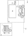
- Fig. 3 shows a typical network topography of the system 2 of Fig. 1 including the remote control server 20.
- the control server 20 has stored within it a list of all of the conference rooms 6a-e with which media streaming sessions can be established.
- Each conference room 6a-e has its own dedicated controller 14a-e and multimedia receiving device 10a-e, data relating to the availability of each is transmitted by network links 24a-e to the control server 20.
- the conference rooms 6a-e are all connected to the same company network.
- the user 3 is then presented with a list 7 of available conference rooms 6a-e to which he can begin streaming media data.
- the list 7 is displayed within the web based user interface via the web browser 5.
- Fig. 4 shows the presenter selecting the conference room 6a in which the meeting is taking place.
- the user 3 selects conference room 6a from the list 7 by moving a mouse cursor 40 over a button within the web based user interface and performing a mouse click.
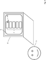
- Fig. 5 shows the controller 14a requiring confirmation from somebody within the conference room 6a which may be a colleague or the user 3.
- a request signal is transmitted to the controller 14a via the first control network link 26a, indicating to said controller 14a that the user 3 wishes to stream media data to the corresponding multimedia receiver 10a.
- the controller 14a Upon receiving the request signal via the first control network link 26a, the controller 14a displays on the touch panel 16a a confirmation message 36.
- This confirmation message 36 conveys to the participants in the room that the user 3 wants to stream media content to the display 12a in their current location, conference room 6a to ensure that the user 3 has selected the correct room.
- One of the participants or the user 3) must accept the request by e.g. pressing a button on the touch panel 16a. This ensures that the correct recipient is in close proximity to the receiver 10a and its associated controller 14a in the correct meeting room 6a.
- the controller 14a sends an acceptance signal back to the laptop 8 via the first control network link 26a to state that the streaming request has been accepted.
- the controller 14a also sends an initiation signal to the multimedia receiver 10a via the second control network link 28a to indicate that it should expect a new WebRTC stream directly from the laptop 8.
- Fig. 6 shows the user 3 selecting the media content he or she wishes to show on the external display 12a within the conference room 6a.
- the user 3 is presented with a choice between sharing the content of his or her screen 42, a specific application 43, or a webcam feed 41.
- the user might choose to stream different types of media content to different external displays. Once the user selects the type of media content to be streamed from the laptop 8 to the multimedia receiver 10a, the media streaming can begin.
- Fig. 7 shows the system 2 once a media streaming network link 32a has been established.
- a media streaming network link 32a between the end-user device i.e. the laptop 8 and the multimedia receiver 10a is established.
- the media streaming network link 32a is a WebRTC session, wherein data is sent browser-to-browser from the web browser 5 running on the laptop 8 to the multimedia receiver 10a.
- the image 42 appearing on the monitor connected to the laptop 8 is then mirrored to the external display 12 as the image 44.
- a third control network link 30a which is established directly between the laptop 8 and the multimedia receiver 10a.
- This third control network link 30a allows for control signals used for e.g. disconnecting from the stream or pausing the stream to be sent directly between the multimedia receiver 10a and the laptop 8 without necessarily needing to be sent via the controller 14a.
- Fig. 8 shows the system of Fig. 1 wherein multiple receivers 10e, 10f, 10g are connected to a matrix device 15.
- the system 2 being used to share different media streams to multiple displays 12e, 12f in the same room.
- the user 3 has selected from the list 7 the conference room 6e in which a meeting is taking place.
- Conference room 6e has two external displays 12e, 12f connected to the matrix device 15, which is in turn connected to the three multimedia receivers 10e, 10f, 10g.
- Each of the multimedia receivers 10e, 10f, 10g is connected to the same controller 14e which in turn has a touch panel 16e.
- first and second displays 12e, 12f are in fact not physically distinct monitors but instead form separate panels making up (at least part of) an array such as a Cyviz display wall 11.
- the user 3 wishes to share his screen on one display 12f, and a webcam feed of a remote user 70 to be shown alongside a further specific application (in this case an application running on the laptop 8) on the other display 12e in virtual windows 13e, 13g respectively.
- the participants within the conference room 6e can select the placement of each media stream (i.e. the shared screen, the application and the webcam video feed) using options presented to them via the controller touch panel 16e.
- the end-user device 8 also transmits a request signal to the controller 14e in the conference room 6e via a first control network link 26e, which in turn notifies the respective multimedia receivers 10e, 10f, 10g via their respective second control network links 28e, 28f, 28g.
- Separate media streaming network links 32e, 32f, 32g are then established between the laptop 8 and the multimedia receivers 10e, 10f, 10g respectively in the same manner as already described hereinabove.
- Each of these media streaming network links 32e, 32f, 32g are separate, dedicated WebRTC sessions, wherein data is sent browser-to-browser from the web browser 5 running on the computer 8 to the respective multimedia receivers 10e, 10f, 10g in parallel.
- the first multimedia receiver 10e obtains data from the first media streaming network link 32e, converts it to a video signal and transmits it to the matrix device 15 via a first matrix link 50e.
- the second and third multimedia receivers 10f, 10g obtain data from the second and third media streaming network links 32f, 32g, convert the respective data to video signals and transmit said video signals to the matrix device 15 via second and third matrix links 50f, 50g respectively.
- the matrix device 15 detects the video signals and uses an Automatic Video Routing Algorithm (known in the art per se and documented with reference to the Cyviz Display Controller) in order to route the video signals to the chosen displays 12e, 12f.
- the video signals from the first and third multimedia receivers 10e, 10g are routed to the first display 12e within virtual windows 13e, 13g via a first HDMI® cable 34e.
- the application 44e is displayed on the first external display 12e in the first virtual window 13e while the video 44g from the webcam is in the second virtual window 44g.
- the matrix device 15 routes the video data from the second multimedia receiver 10f to the second display 12f via a second HDMI® cable 34f.
- the image 42 appearing on the monitor connected to the laptop 8 is then mirrored to the second external display 12f as the image 44f.
- Fig. 9 illustrates the system 2 of Fig. 1 wherein a user 3 wishes to set up a media streaming session from a remote location such as an office 4a to the conference room 6a.
- a remote location such as an office 4a to the conference room 6a.
- the user 3, located in his office 4a wishes to share his screen to provide a presentation to a group of colleagues situated in a conference room 6a, wherein the presentation should be displayed on a large external monitor 12a.
- the receiver 10a is physically connected to the monitor 12a by a HDMI® cable 34a.
- the user 3 opens up his web browser 5 on his computer 8 and navigates to a particular web address which provides a web based user interface for establishing a streaming session.
- the user 3 uses this interface to indicate that he would like to set up a streaming session with the participants in the conference room 6a.
- Fig. 10 shows the controller 14a requiring confirmation from participants within the conference room 6a. After the user 3 has selected the conference room 6a, a request signal is transmitted to the controller 14a via the first control network link 26a, indicating to said controller 14a that the user 3 wishes to stream media data to the corresponding multimedia receiver 10a.
- the controller 14a Upon receiving the request signal via the first control network link 26a, the controller 14a displays on the touch panel 16a a confirmation message 36.
- This confirmation message 36 conveys to the participants in the room that the user 3 wants to stream media content to the display 12a in their current location, conference room 6a.
- One of the participants must accept the request by e.g. pressing a button on the touch panel 16a. This ensures that the correct recipient is in close proximity to the receiver 10a and its associated controller 14a in the correct meeting room 6a.
- the controller 14a sends an acceptance signal back to the computer 8 via the first control network link 26a to state that the streaming request has been accepted.
- the controller 14a also sends an initiation signal to the multimedia receiver 10a via the second control network link 28a to indicate that it should expect a new WebRTC stream directly from the computer 8.
- Fig. 11 shows the end-user device 8 requiring a PIN code for mutual authentication. While the stream could be established immediately following the confirmation within the conference room 6a as described above with reference to Fig. 10 , in this particular embodiment the system 2 requires mutual authentication.
- the controller 14a displays a four digit PIN code 38 on the touch panel 16a. This same PIN code 38 must then be entered into the browser 5 via a PIN confirmation screen 40 within the web-based user interface. Since the PIN code 38 must be relayed to the user 3, he can be confident that he has indeed selected the correct room and that any data he chooses to stream will not be made available to unintended participants.
- Fig. 12 shows the system 2 once a media streaming network link 32a has been established. After the system 2 has performed all of the required confirmation steps, a media streaming network link 32a between the end-user device i.e. the computer 8 and the multimedia receiver 10a is established.
- the media streaming network link 32a is a WebRTC session, wherein data is sent browser-to-browser from the web browser 5 running on the computer 8 to the multimedia receiver 10a.
- the image 42 appearing on the monitor connected to the laptop 8 is then mirrored to the external display 12 as the image 44.
- a third control network link 30a which is established directly between the computer 8 and the multimedia receiver 10a.
- This third control network link 30a allows for control signals used for e.g. disconnecting from the stream or pausing the stream to be sent directly between the multimedia receiver 10a and the computer 8 without necessarily needing to be sent via the controller 14a.
- Fig. 13 shows the system 2 being used to share the user's screen 42 to multiple locations 6a, 6b.
- the user 3 has selected two conference rooms 6a, 6b available for selection from the list 7.
- the connections between the computer 8 and the devices within the first conference room 6a are the same as described hereinbefore with reference to Figs. 2 to 12 .
- the end-user device 8 also transmits a request signal to the controller 14b in the second conference room 6b via a further control network link 26b.
- a second media streaming network link 32b between the end-user device (i.e. the computer 8) and the multimedia receiver 10b is established.
- the second media streaming network link 32b is a separate, dedicated WebRTC session, wherein data is sent browser-to-browser from the web browser 5 running on the computer 8 to the multimedia receiver 10b in parallel to the data being sent via the first media streaming network link 32a.
- Fig. 14 shows the system 2 being used to share different media streams to multiple displays in the same room.
- the user 3 has selected from the list 7 a conference room 6e that has two external displays 12e, 12f each being connected to a separate multimedia receiver 10e, 10f respectively.
- Each of the multimedia receivers 10e, 10f is connected to one central controller 14e which in turn has a touch panel 16e.
- the user 3 wishes to share his screen on one display 12e and have a video feed from his webcam 46 be shown on the other display 12f. It is however envisioned that the participants within the conference room 6e could select the placement of each media stream (i.e. the shared screen and the webcam video feed) using options presented to them via the controller touch panel 16e.
- the end-user device 8 also transmits a request signal to the controller 14e in the conference room 6e via a first control network link 26e, which in turn notifies the respective multimedia receivers 10e, 10f via their respective second control network links 28e, 28f.
- Separate media streaming network links 32e, 32f are then established between the end-user device (i.e. the computer 8) and the multimedia receivers 10e, 10f respectively in the same manner as already described hereinabove.
- Each of these media streaming network links 32e, 32f are separate, dedicated WebRTC sessions, wherein data is sent browser-to-browser from the web browser 5 running on the computer 8 to the respective multimedia receivers 10e, 10f in parallel.
- the first multimedia receiver 10e obtains data from the first media streaming network link 32e, converts it to a video signal and transmits it to the first display 12e via a first HDMI® cable 34e.
- the image 42 appearing on the monitor connected to the computer 8 is then mirrored to the first external display 12e as the image 44e.
- the second multimedia receiver 10f obtains data from the second media streaming network link 32f, converts it to a video signal and transmits it to the second display 12f via a second HDMI® cable 34f.
- the video 44f from the webcam 46 is then displayed on the second external display 12f.
- first and second displays 12e, 12f may not be physically distinct monitors but could be separate panels making up (at least part of) an array such as a Cyviz display wall.
- Fig. 15 shows the system 2 in an alternative configuration wherein the controller 14g provides a one-time authorisation (OTA) code 60 in order to establish a media streaming network link.
- OTA one-time authorisation
- the user 3 in conference room 6g wishes to share his screen on the display 12g.
- an OTA code option is provided by the system 2.
- An OTA code 60 is generated by the control server 20 and provided to the controller 14g via a network link 24g.
- the multimedia receiver 10g displays the OTA code 60 on the display 12g and in this case the OTA code 60 reads "red dog". It will of course be appreciated that the OTA code 60 could instead be displayed on the touch panel 16g.
- the user 3 enters "red dog" into a dialogue box 62 within the web browser 5 on his laptop 8, which is then relayed to the control server 20.
- the control server 20 has a list of current OTA codes and matches the entry "red dog" to the receiver 10g and associated controller 14g (there is a one-to-one relationship between the OTA codes and the receivers in the list stored on the server 20).
- a WebRTC media streaming network link 32g between the end-user device i.e. the laptop 8 and the multimedia receiver 10g is then "seamlessly" established without any further intervention by the user 3.
- this approach requires the user 3 to be present in the same room 6g as the intended receiver 10g, or in communication with someone in the room, thereby achieving proximity detection.
- Fig. 16 shows a block diagram of a system 2' in accordance with a further embodiment of the present invention, wherein like reference numerals denote like elements.
- the system 2' is split across different rooms 4', 6' but also supports users wishing to share their screen onto an external display in the same room but without using a cable to do so, as described previously with reference to Figs. 2 to 7 .
- the system 2' of Fig. 16 further comprises a scheduling server 64 and an external user catalogue 70 in a remote location 18'.
- the scheduling server 64 and external user catalogue 70 are shown as being in the same remote location 18' as the control server 20', however it will be appreciated that this does not necessarily need to be the case and these servers 20', 64, 70 could be in different physical locations to one another.
- the servers 20', 64, 70 may not be physically distinct but may be different server applications running in parallel on common server hardware.
- the scheduling server 64 is arranged to store meeting information regarding one or more users and/or one more room bookings. This meeting information may be used by the system 2' when determining whether or not a user is proximate to the room 6' (or at least is supposed to be) e.g. to present on the display 12' within the room 6'.
- the scheduling server 64 may provide this meeting information to the controller 14' via a scheduling network link 66, such that the controller 14' is aware of the expected participation of the user(s) in a scheduled meeting and/or is aware of which user(s) are scheduled to be in the room 6' according to room booking information stored by the scheduling server 64.
- the controller 14' is active in pulling meeting information from the scheduling server 64, for example intermittently, regularly or continuously fetching room booking information for the room 6' via the scheduling network link 66.
- the controller 14' does not need to access individual users' calendars as the meeting information provided via the scheduling network link 66 may be limited to a list of users booked to have a meeting in the room 6'.
- Room booking information may be displayed on the touch panel 16' and used to initiate a media streaming session upon receiving a user input via the controller interface e.g. to start the scheduled meeting.
- the scheduling server 64 may comprise a Microsoft@ Exchange Server or similar.
- the scheduling server 64 may store calendar information for users, including the locations of scheduled meetings at any given time. This information may be input to a user's calendar using their end-user device 8' which is connected to the scheduling server 64 through an exchange network link 68, or by any other means known in the art per se.
- the control server 20' is arranged to acquire data from the controller 14' via a network link 24'. This data now includes meeting information or a subset of such information, for example the expected participants for a meeting that is scheduled to take place in the room 6'.
- the controller 14' is arranged to push meeting information, e.g. room scheduling with participant information, to the control server 20'.
- the control server 20' can then create a database by aggregating meeting information from multiple controllers 14' in multiple rooms 6', without accessing individuals' calendars.
- the control server 20' is then able to predict where a user is intended to be.
- control server 20' is now provided with trusted information about the participants of a meeting in the room 6', there is no need to confirm proximity for a user of the end-user device 8' and the media streaming session may be initiated automatically without needing a second user input for confirmation.
- the control server 20' is sure of the user's identity before selecting the multimedia receiver device10' from the list based on the meeting information sent from the controller 14'.
- the end-user device 8' may present a web page (such as www.easyconnect.cyviz.com) with a "login" function, which allows the user to enter credentials which are sent to the control server 20' for verification.
- the control server 20' uses the external user catalogue 70, for example Microsoft@ Active Directory, to actually verify the credentials.
- the control server 20' provides a link between the external user catalogue 70 and the meeting information originating from the scheduling server 64, so that the system 2' can use the same "user object" when attempting to match information from different sources i.e. the controller 14' and the end-user device 8'.
- the login credentials entered into the end-user device 8' and the user information provided by the external user catalogue 70 after a successful authentication may take the form of e.g. a unique user number, user email address, or Globally Unique Identifier (GUID), as is known in the art.
- the external user catalogue 70 has a user verification network link 72 with the control server 20' and a network link 74 with the scheduling server 64.
- the controller 14' may also push meeting participant information to the scheduling server 64 via the location information network link 66.
- a host user may be able to log in to the controller 14' when they find a suitable location (e.g. a vacant conference room 6').
- the controller 14' may then inform the scheduling server 64 that the host of the meeting (or, in some arrangements, a different user invited to the meeting) has logged into the controller 14' and thus the location for the meeting stored on the scheduling server 64 can be updated to reflect this.
- This updated meeting information may then be used in order to determine which multimedia receiver device(s) should be available to meeting participants.
- the end-user device 8' is connected to the scheduling server 64 via the exchange network link 68, the user can be automatically presented an appropriate receiver 10' in the room 6' based on the updated meeting information. Again, user identity can be verified for the meeting participants based on information provided by the external user catalogue 70.
- the scheduling server 64 provides a trusted source of information as to the whereabouts of users, it may not be necessary in such arrangements to carry out any further confirmation steps (e.g. inputting access codes including OTA codes as described above), although these may of course still be carried out optionally if desired.
- the meeting participant logged into the end-user device 8' does not have to be in the same room 6' as the other meeting participants.
- the system 2' is network-centric, once the identity of the user has been verified, the media streaming session from the end-user device 8' to the receiver 10' can be initiated regardless of whether that user is physically present in the scheduled meeting. In some examples, this can enable screen sharing between remote locations while an audio link may be provided independently, for example using a telephone connection or web meeting e.g. Skype session.
- the meeting information could be combined with location information received by the control server 20', e.g. from a location system as described previously with reference to Fig. 1 , in order to confirm that one or more of the intended participants are indeed present.
- the control server 20' needs to be able to match the location information received from a location system (e.g. location system 21 in Fig. 1 ) to the identity of the users of the end-user device 8' and controller 14'.
- a location system 21 may be connected to the control server 20' and both may be connected to the same external user catalogue 70 to enable integration of location information in a way that uniquely identifies the same user across all information sources.
Landscapes
- Engineering & Computer Science (AREA)
- Computer Networks & Wireless Communication (AREA)
- Signal Processing (AREA)
- Multimedia (AREA)
- Automation & Control Theory (AREA)
- Computer Hardware Design (AREA)
- Computer Security & Cryptography (AREA)
- Computing Systems (AREA)
- General Engineering & Computer Science (AREA)
- Information Transfer Between Computers (AREA)
- Two-Way Televisions, Distribution Of Moving Picture Or The Like (AREA)
Claims (15)
- System (2) zum Streamen von Daten, die Multimedia-Inhalt (41, 42, 43) umfassen, wobei das System (2) Folgendes umfasst:eine oder mehrere Steuerungen (14), die eine Steuerungsschnittstelle (16) umfassen, die angeordnet ist, um über eine erste Steuernetzverbindung (26) mit einer Endbenutzervorrichtung (8) verbunden zu werden;eine oder mehrere Multimedia-Empfängervorrichtungen (10), die eine Multimedia-Schnittstelle umfassen, die geeignet ist für die Verbindung mit einer Videoempfangsvorrichtung (12), wobei jede der einen oder mehreren Multimedia-Empfängervorrichtungen (10) angeordnet ist, um über eine zweite Steuernetzverbindung (28) mit einer zugehörigen Steuerung (14) verbunden zu werden, und weiter angeordnet ist, um über eine Medienstreaming-Netzwerksverbindung (32) direkt mit der Endbenutzervorrichtung (8) verbunden zu werden;einen Steuerungsserver (20), der eine Liste (7) der einen oder mehreren Multimedia-Empfängervorrichtungen (10) und zugehörigen Steuerungen (14) hostet;wobei die Endbenutzervorrichtung (8) eine Benutzerschnittstelle (5) umfasst, die mit dem Steuerungsserver (20) verbunden ist, wobei die Benutzerschnittstelle (5) angeordnet ist für die Auswahl einer Multimedia-Empfängervorrichtung (10) aus der Liste (7) und des zu streamenden Multimedia-Inhalts (41, 42, 43);wobei die Endbenutzervorrichtung (8) und die zu der ausgewählten Multimedia-Empfängervorrichtung (10) zugehörige Steuerung (14) angeordnet sind, um eine Mediastreaming-Sitzung über die Medienstreaming-Netzwerksverbindung (32) zwischen der Endbenutzervorrichtung (8) und der ausgewählten Multimedia-Empfängervorrichtung (10) nach Erhalt einer Benutzereingabe (36) über die Steuerungsschnittstelle oder die Endbenutzervorrichtung (8) zu initiieren.
- System (2) nach Anspruch 1, wobei die Benutzereingabe (36) eine erste Bestätigung (36) umfasst, dass die Medienstreaming-Netzwerksverbindung (32) mit der ausgewählten Multimedia-Empfängervorrichtung (10) aufgebaut werden soll.
- System (2) nach Anspruch 1 oder 2, wobei die Endbenutzervorrichtung (8) und die zu der ausgewählten Multimedia-Empfängervorrichtung (10) zugehörige Steuerung (14) angeordnet sind, um die Mediastreaming-Sitzung nur nach einer zweiten Bestätigung (38) zu initiieren, die über die Benutzerschnittstelle (5) in die Endbenutzervorrichtung (8) eingegeben wird.
- System (2) nach Anspruch 3, wobei die zweite Bestätigung (38) von der Endbenutzervorrichtung (8) über die erste Steuernetzverbindung (26) an die Steuerung (14) übertragen wird.
- System (2) nach Anspruch 3 oder 4, wobei die zweite Bestätigung einen Zugangscode (38) umfasst.
- System (2) nach Anspruch 5, wobei der Zugangscode durch den Steuerungsserver (20) generiert wird.
- System (2) nach Anspruch 6, das angeordnet ist, um den Zugangscode über eine Anzeige anzuzeigen, die mit dem Multimediaempfänger (10) verbunden ist, oder über die Steuerungsschnittstelle.
- System (2) nach Anspruch 6 oder 7, wobei die vom Steuerungsserver (20) gehostete Liste (7) eine Liste (7) von gegenwärtigen Einmal-Autorisierungscodes (OTA) für jede der einen oder mehreren Multimedia-Empfängervorrichtungen (10) und zugehörigen Steuerungen (14) umfasst.
- System (2) nach einem der vorstehenden Ansprüche, weiter umfassend eine dritte Steuernetzverbindung (30) zwischen der Endbenutzervorrichtung (8) und der ausgewählten Multimedia-Empfängervorrichtung (10).
- System (2) nach einem der vorstehenden Ansprüche, umfassend eine Vielzahl von Multimedia-Empfängervorrichtungen (10), von denen jede eine Multimedia-Schnittstelle umfasst, die zur Verbindung mit einer Videoempfangsvorrichtung (12) geeignet ist, wobei jede Multimedia-Empfängervorrichtung eine dedizierte Medienstreaming-Netzwerksverbindung (32) mit einer Endbenutzervorrichtung (8) aufweist.
- System (2) nach Anspruch 10, weiter umfassend eine Matrixvorrichtung (15), die eine Vielzahl von Multimedia-Schnittstelleeingaben und mindestens eine Multimedia-Schnittstellenausgabe umfasst, wobei die Matrixvorrichtung (15) zwischen der Vielzahl von Multimedia-Empfängervorrichtungen (10) und ihren zugehörigen Steuerungen (14) verbunden ist, wobei die Matrixvorrichtung (15) angeordnet ist, um Medieninhalt (41, 42, 43), der über jede Medienstreaming-Netzwerksverbindung (32) gestreamt wird, an die Videoempfangsvorrichtung (12) zu leiten.
- System (2) nach einem der vorstehenden Ansprüche, weiter umfassend ein Benutzerstandortsystem (21), das angeordnet ist, um dem Steuerungsserver (20) Benutzerstandortinformationen bereitzustellen.
- System (2) nach Anspruch 12, wobei die Auswahl einer Multimedia-Empfängervorrichtung (10) aus der Liste (7) zumindest teilweise auf der Grundlage der Benutzerstandortinformationen automatisch ausgeführt wird.
- System (2) nach einem der vorstehenden Ansprüche, weiter umfassend einen Planungsserver (21), der angeordnet ist, um einer Steuerung der einen oder mehreren Steuerungen (14) Besprechungsinformationen bereitzustellen.
- Verfahren zum Streamen von Daten, die Multimedia-Inhalt (41, 42, 43) umfassen, von einer Endbenutzervorrichtung (8), die eine Benutzerschnittstelle (5) aufweist, an eine Multimedia-Empfängervorrichtung (10), die eine Multimedia-Schnittstelle umfasst, die geeignet ist für die Verbindung mit einer Videoempfangsvorrichtung (12), wobei das Verfahren Folgendes umfasst:Verbinden der Benutzerschnittstelle (5) der Endbenutzervorrichtung (8) mit einem Steuerungsserver (20), um auf eine Liste (7) von einer oder mehreren Multimedia-Empfängervorrichtungen (10) und zugehörigen Steuerungen (14) zuzugreifen;Auswählen von einem oder mehreren Multimediaempfängern (10) aus der Liste (7) über die Benutzerschnittstelle (5);Übertragen einer Streaminganfrage über eine erste Steuernetzverbindung (26) zwischen der Endbenutzervorrichtung (8) und einer Steuerung (14), die eine Steuerungsschnittstelle aufweist, die zu der ausgewählten Multimedia-Empfängervorrichtung (10) zugehörig ist;Empfangen einer Benutzereingabe (36) über die Steuerungsschnittstelle oder über die Endbenutzervorrichtung (8), um die Streaminganfrage anzunehmen;Übertragen eines Initiierungsbefehls von der Steuerung (14) an die ausgewählte/n Multimedia-Empfängervorrichtung/en (10) über eine zweite Steuernetzverbindung (28);Auswählen des über die Benutzerschnittstelle (5) zu streamenden Multimedia-Inhalts (41, 42, 43); undInitiieren einer Mediastreaming-Sitzung über eine Medienstreaming-Netzwerksverbindung (32) zwischen der Endbenutzervorrichtung (8) und der/den ausgewählten Multimedia-Empfängervorrichtung/en (10);wobei die Steuerungsschnittstelle angeordnet ist, um über die erste Steuernetzverbindung (26) mit der Endbenutzervorrichtung (8) verbunden zu werden; undwobei die Multimedia-Empfängervorrichtung/en (10) angeordnet ist/sind, um über die zweite Steuernetzverbindung (28) mit der/den zugehörigen Steuerung/en (14) verbunden zu werden, und weiter angeordnet ist/sind, um über die Medienstreaming-Netzwerksverbindung (32)direkt mit der Endbenutzervorrichtung (8) verbunden zu werden.
Applications Claiming Priority (2)
| Application Number | Priority Date | Filing Date | Title |
|---|---|---|---|
| GBGB1609986.3A GB201609986D0 (en) | 2016-06-08 | 2016-06-08 | Streamed communications |
| PCT/GB2017/051670 WO2017212279A1 (en) | 2016-06-08 | 2017-06-08 | Streamed communications |
Publications (2)
| Publication Number | Publication Date |
|---|---|
| EP3469768A1 EP3469768A1 (de) | 2019-04-17 |
| EP3469768B1 true EP3469768B1 (de) | 2020-12-30 |
Family
ID=56508240
Family Applications (1)
| Application Number | Title | Priority Date | Filing Date |
|---|---|---|---|
| EP17730904.4A Active EP3469768B1 (de) | 2016-06-08 | 2017-06-08 | Gestreamte kommunikation |
Country Status (5)
| Country | Link |
|---|---|
| US (1) | US11102254B2 (de) |
| EP (1) | EP3469768B1 (de) |
| CN (1) | CN109565454B (de) |
| GB (1) | GB201609986D0 (de) |
| WO (1) | WO2017212279A1 (de) |
Families Citing this family (9)
| Publication number | Priority date | Publication date | Assignee | Title |
|---|---|---|---|---|
| US10873617B2 (en) * | 2017-07-28 | 2020-12-22 | Barco N.V. | Method and system for streaming data over a network |
| EP3547611A1 (de) * | 2018-03-30 | 2019-10-02 | Ricoh Company, Ltd. | Kommunikationssystem, kommunikationsverfahren und informationsverarbeitungsvorrichtung |
| ES2754848B2 (es) | 2018-10-17 | 2021-11-23 | Fernandez Luis Lopez | Sistema y método para la asignación inteligente de ancho de banda en sistemas de comunicación multimedia de pista múltiple |
| US11042222B1 (en) | 2019-12-16 | 2021-06-22 | Microsoft Technology Licensing, Llc | Sub-display designation and sharing |
| US11093046B2 (en) * | 2019-12-16 | 2021-08-17 | Microsoft Technology Licensing, Llc | Sub-display designation for remote content source device |
| US11404028B2 (en) | 2019-12-16 | 2022-08-02 | Microsoft Technology Licensing, Llc | Sub-display notification handling |
| US11487423B2 (en) | 2019-12-16 | 2022-11-01 | Microsoft Technology Licensing, Llc | Sub-display input areas and hidden inputs |
| CN113590567B (zh) * | 2020-04-30 | 2023-12-19 | 明基智能科技(上海)有限公司 | 会议资料分享方法与会议资料分享系统 |
| US20230050116A1 (en) * | 2021-08-10 | 2023-02-16 | Logitech Europe S.A. | Electronic system and method for claiming and reserving work areas |
Family Cites Families (22)
| Publication number | Priority date | Publication date | Assignee | Title |
|---|---|---|---|---|
| US20050134682A1 (en) * | 2003-12-22 | 2005-06-23 | Epiphan Consulting Inc. | Network based conference system |
| CN101141485A (zh) | 2007-10-19 | 2008-03-12 | 中兴通讯股份有限公司 | 一种基于万维网的用户侧接入会议电视的系统及方法 |
| US20090228808A1 (en) | 2008-03-05 | 2009-09-10 | The Nasdaq Omx Group, Inc. | Web Conferencing |
| CN101287014B (zh) | 2008-06-10 | 2011-10-26 | 北京邮电大学 | 一种实现流媒体业务的方法、系统及装置 |
| US9032461B2 (en) | 2008-09-12 | 2015-05-12 | Centurylink Intellectual Property Llc | System and method for video conferencing through a television forwarding device |
| NO332231B1 (no) | 2010-01-18 | 2012-08-06 | Cisco Systems Int Sarl | Metode for a parre datamaskiner og videokonferanseinnretninger |
| US8909704B2 (en) * | 2010-04-29 | 2014-12-09 | Cisco Technology, Inc. | Network-attached display device as an attendee in an online collaborative computing session |
| US20110271332A1 (en) | 2010-04-30 | 2011-11-03 | American Teleconferencing Services Ltd. | Participant Authentication via a Conference User Interface |
| US9041765B2 (en) * | 2010-05-12 | 2015-05-26 | Blue Jeans Network | Systems and methods for security and privacy controls for videoconferencing |
| CN101984659A (zh) * | 2010-11-16 | 2011-03-09 | 中兴通讯股份有限公司 | 视频会议通话中灵活发送视频源的方法、终端及系统 |
| US9781385B2 (en) * | 2013-03-15 | 2017-10-03 | Blue Jeans Network | User interfaces for presentation of audio/video streams |
| US9398056B2 (en) | 2013-05-31 | 2016-07-19 | Vidyo, Inc. | Systems and methods for room system pairing in video conferencing |
| CN104427296B (zh) * | 2013-09-05 | 2019-03-01 | 华为终端(东莞)有限公司 | 视频会议中媒体流的传输方法与装置 |
| GB201317294D0 (en) | 2013-09-30 | 2013-11-13 | Microsoft Corp | Device pairing |
| US9179097B2 (en) | 2013-10-23 | 2015-11-03 | Google Inc. | Control of a video conference system using personal devices |
| WO2015199680A1 (en) * | 2014-06-25 | 2015-12-30 | Intel Corporation | Techniques to enhance wireless personal area network performance under interference conditions |
| US9710142B1 (en) * | 2016-02-05 | 2017-07-18 | Ringcentral, Inc. | System and method for dynamic user interface gamification in conference calls |
| US10264035B2 (en) * | 2016-02-23 | 2019-04-16 | At&T Intellectual Property I, L.P. | Method and apparatus for architecting multimedia conferencing services using SDN |
| US10673641B2 (en) * | 2016-03-11 | 2020-06-02 | Lenovo Enterprise Solutions (Singapore) Pte. Ltd | Connecting to a conference device |
| US10594785B2 (en) * | 2016-03-11 | 2020-03-17 | Intel Corporation | Transitioning from an infrastructure based wireless connection to a peer to peer (P2P) wireless connection |
| US10025550B2 (en) * | 2016-03-15 | 2018-07-17 | Intel Corporation | Fast keyboard for screen mirroring |
| US10686873B2 (en) * | 2016-03-16 | 2020-06-16 | Polycom, Inc. | Seamless transition of a video session between a mesh topology and a centralized bridge topology |
-
2016
- 2016-06-08 GB GBGB1609986.3A patent/GB201609986D0/en not_active Ceased
-
2017
- 2017-06-08 WO PCT/GB2017/051670 patent/WO2017212279A1/en not_active Ceased
- 2017-06-08 US US16/308,670 patent/US11102254B2/en active Active
- 2017-06-08 CN CN201780039827.5A patent/CN109565454B/zh not_active Expired - Fee Related
- 2017-06-08 EP EP17730904.4A patent/EP3469768B1/de active Active
Non-Patent Citations (1)
| Title |
|---|
| None * |
Also Published As
| Publication number | Publication date |
|---|---|
| CN109565454A (zh) | 2019-04-02 |
| GB201609986D0 (en) | 2016-07-20 |
| US11102254B2 (en) | 2021-08-24 |
| WO2017212279A1 (en) | 2017-12-14 |
| EP3469768A1 (de) | 2019-04-17 |
| CN109565454B (zh) | 2021-10-01 |
| US20190166169A1 (en) | 2019-05-30 |
Similar Documents
| Publication | Publication Date | Title |
|---|---|---|
| US11102254B2 (en) | Streamed communications | |
| US10862987B2 (en) | System and method for collaborative telepresence amongst non-homogeneous endpoints | |
| US12277309B2 (en) | Simplified sharing of content among computing devices | |
| US11558437B2 (en) | Communication system and method of using the same | |
| EP3266192B1 (de) | Kommunikationssystem und verfahren zur verwendung davon | |
| US20070005809A1 (en) | Network information processing system and network information processing method | |
| US8909704B2 (en) | Network-attached display device as an attendee in an online collaborative computing session | |
| US9532003B2 (en) | Information processing apparatus, information processing system, and non-transitory computer readable medium | |
| EP1427144A1 (de) | Netzwerkinformationsverarbeitungssystem und informationsverarbeitungsverfahren | |
| US11012665B2 (en) | Bridging video conference room system and associated methods | |
| JP2021009522A (ja) | リソース予約システム、登録端末、設定方法 | |
| KR101771400B1 (ko) | 회의실객체를 이용한 화상회의 방법 | |
| EP3382936B1 (de) | Übertragungsverwaltungssystem, übertragungssystem und aufzeichnungsmedium | |
| US20090240770A1 (en) | Establishing a Remotely Hosted Conference Initiated with One Button Push | |
| JP2021077021A (ja) | リソース予約システム、リソース利用方法 | |
| US20210250194A1 (en) | Personal calendar bridge for room-based conferencing | |
| KR102510615B1 (ko) | 화상회의 중개플랫폼과 이를 이용한 화상회의 초청 및 수신방법 | |
| US9420226B2 (en) | Apparatus, system, and method of managing data transmission, and recording medium storing data transmission management program | |
| WO2018117956A1 (en) | Method and system for displaying data | |
| JP2003087248A (ja) | ネットワーク情報処理システム及びネットワーク構築方法 | |
| JP2003087250A (ja) | ネットワーク情報処理システム及び情報処理方法 | |
| JP2003087288A (ja) | ネットワーク情報処理システム及び情報処理方法 | |
| KR20180108165A (ko) | 웹객체를 이용한 화상회의 방법 | |
| JP2003091489A (ja) | ネットワーク情報処理システム及び情報処理方法 | |
| JP2003091488A (ja) | ネットワーク情報処理システム及び情報処理方法 |
Legal Events
| Date | Code | Title | Description |
|---|---|---|---|
| STAA | Information on the status of an ep patent application or granted ep patent |
Free format text: STATUS: UNKNOWN |
|
| STAA | Information on the status of an ep patent application or granted ep patent |
Free format text: STATUS: THE INTERNATIONAL PUBLICATION HAS BEEN MADE |
|
| PUAI | Public reference made under article 153(3) epc to a published international application that has entered the european phase |
Free format text: ORIGINAL CODE: 0009012 |
|
| STAA | Information on the status of an ep patent application or granted ep patent |
Free format text: STATUS: REQUEST FOR EXAMINATION WAS MADE |
|
| 17P | Request for examination filed |
Effective date: 20190104 |
|
| AK | Designated contracting states |
Kind code of ref document: A1 Designated state(s): AL AT BE BG CH CY CZ DE DK EE ES FI FR GB GR HR HU IE IS IT LI LT LU LV MC MK MT NL NO PL PT RO RS SE SI SK SM TR |
|
| AX | Request for extension of the european patent |
Extension state: BA ME |
|
| DAV | Request for validation of the european patent (deleted) | ||
| DAX | Request for extension of the european patent (deleted) | ||
| GRAP | Despatch of communication of intention to grant a patent |
Free format text: ORIGINAL CODE: EPIDOSNIGR1 |
|
| STAA | Information on the status of an ep patent application or granted ep patent |
Free format text: STATUS: GRANT OF PATENT IS INTENDED |
|
| INTG | Intention to grant announced |
Effective date: 20200716 |
|
| GRAS | Grant fee paid |
Free format text: ORIGINAL CODE: EPIDOSNIGR3 |
|
| GRAA | (expected) grant |
Free format text: ORIGINAL CODE: 0009210 |
|
| STAA | Information on the status of an ep patent application or granted ep patent |
Free format text: STATUS: THE PATENT HAS BEEN GRANTED |
|
| AK | Designated contracting states |
Kind code of ref document: B1 Designated state(s): AL AT BE BG CH CY CZ DE DK EE ES FI FR GB GR HR HU IE IS IT LI LT LU LV MC MK MT NL NO PL PT RO RS SE SI SK SM TR |
|
| REG | Reference to a national code |
Ref country code: GB Ref legal event code: FG4D |
|
| REG | Reference to a national code |
Ref country code: AT Ref legal event code: REF Ref document number: 1351027 Country of ref document: AT Kind code of ref document: T Effective date: 20210115 |
|
| REG | Reference to a national code |
Ref country code: DE Ref legal event code: R096 Ref document number: 602017030461 Country of ref document: DE |
|
| REG | Reference to a national code |
Ref country code: IE Ref legal event code: FG4D |
|
| PG25 | Lapsed in a contracting state [announced via postgrant information from national office to epo] |
Ref country code: RS Free format text: LAPSE BECAUSE OF FAILURE TO SUBMIT A TRANSLATION OF THE DESCRIPTION OR TO PAY THE FEE WITHIN THE PRESCRIBED TIME-LIMIT Effective date: 20201230 Ref country code: FI Free format text: LAPSE BECAUSE OF FAILURE TO SUBMIT A TRANSLATION OF THE DESCRIPTION OR TO PAY THE FEE WITHIN THE PRESCRIBED TIME-LIMIT Effective date: 20201230 Ref country code: GR Free format text: LAPSE BECAUSE OF FAILURE TO SUBMIT A TRANSLATION OF THE DESCRIPTION OR TO PAY THE FEE WITHIN THE PRESCRIBED TIME-LIMIT Effective date: 20210331 |
|
| REG | Reference to a national code |
Ref country code: AT Ref legal event code: MK05 Ref document number: 1351027 Country of ref document: AT Kind code of ref document: T Effective date: 20201230 |
|
| REG | Reference to a national code |
Ref country code: NO Ref legal event code: T2 Effective date: 20201230 |
|
| PG25 | Lapsed in a contracting state [announced via postgrant information from national office to epo] |
Ref country code: SE Free format text: LAPSE BECAUSE OF FAILURE TO SUBMIT A TRANSLATION OF THE DESCRIPTION OR TO PAY THE FEE WITHIN THE PRESCRIBED TIME-LIMIT Effective date: 20201230 Ref country code: LV Free format text: LAPSE BECAUSE OF FAILURE TO SUBMIT A TRANSLATION OF THE DESCRIPTION OR TO PAY THE FEE WITHIN THE PRESCRIBED TIME-LIMIT Effective date: 20201230 Ref country code: BG Free format text: LAPSE BECAUSE OF FAILURE TO SUBMIT A TRANSLATION OF THE DESCRIPTION OR TO PAY THE FEE WITHIN THE PRESCRIBED TIME-LIMIT Effective date: 20210330 |
|
| REG | Reference to a national code |
Ref country code: NL Ref legal event code: MP Effective date: 20201230 |
|
| PG25 | Lapsed in a contracting state [announced via postgrant information from national office to epo] |
Ref country code: HR Free format text: LAPSE BECAUSE OF FAILURE TO SUBMIT A TRANSLATION OF THE DESCRIPTION OR TO PAY THE FEE WITHIN THE PRESCRIBED TIME-LIMIT Effective date: 20201230 |
|
| REG | Reference to a national code |
Ref country code: LT Ref legal event code: MG9D |
|
| PG25 | Lapsed in a contracting state [announced via postgrant information from national office to epo] |
Ref country code: CZ Free format text: LAPSE BECAUSE OF FAILURE TO SUBMIT A TRANSLATION OF THE DESCRIPTION OR TO PAY THE FEE WITHIN THE PRESCRIBED TIME-LIMIT Effective date: 20201230 Ref country code: EE Free format text: LAPSE BECAUSE OF FAILURE TO SUBMIT A TRANSLATION OF THE DESCRIPTION OR TO PAY THE FEE WITHIN THE PRESCRIBED TIME-LIMIT Effective date: 20201230 Ref country code: LT Free format text: LAPSE BECAUSE OF FAILURE TO SUBMIT A TRANSLATION OF THE DESCRIPTION OR TO PAY THE FEE WITHIN THE PRESCRIBED TIME-LIMIT Effective date: 20201230 Ref country code: PT Free format text: LAPSE BECAUSE OF FAILURE TO SUBMIT A TRANSLATION OF THE DESCRIPTION OR TO PAY THE FEE WITHIN THE PRESCRIBED TIME-LIMIT Effective date: 20210430 Ref country code: SK Free format text: LAPSE BECAUSE OF FAILURE TO SUBMIT A TRANSLATION OF THE DESCRIPTION OR TO PAY THE FEE WITHIN THE PRESCRIBED TIME-LIMIT Effective date: 20201230 Ref country code: RO Free format text: LAPSE BECAUSE OF FAILURE TO SUBMIT A TRANSLATION OF THE DESCRIPTION OR TO PAY THE FEE WITHIN THE PRESCRIBED TIME-LIMIT Effective date: 20201230 |
|
| PG25 | Lapsed in a contracting state [announced via postgrant information from national office to epo] |
Ref country code: AT Free format text: LAPSE BECAUSE OF FAILURE TO SUBMIT A TRANSLATION OF THE DESCRIPTION OR TO PAY THE FEE WITHIN THE PRESCRIBED TIME-LIMIT Effective date: 20201230 Ref country code: PL Free format text: LAPSE BECAUSE OF FAILURE TO SUBMIT A TRANSLATION OF THE DESCRIPTION OR TO PAY THE FEE WITHIN THE PRESCRIBED TIME-LIMIT Effective date: 20201230 |
|
| PG25 | Lapsed in a contracting state [announced via postgrant information from national office to epo] |
Ref country code: IS Free format text: LAPSE BECAUSE OF FAILURE TO SUBMIT A TRANSLATION OF THE DESCRIPTION OR TO PAY THE FEE WITHIN THE PRESCRIBED TIME-LIMIT Effective date: 20210430 |
|
| REG | Reference to a national code |
Ref country code: DE Ref legal event code: R097 Ref document number: 602017030461 Country of ref document: DE |
|
| PG25 | Lapsed in a contracting state [announced via postgrant information from national office to epo] |
Ref country code: AL Free format text: LAPSE BECAUSE OF FAILURE TO SUBMIT A TRANSLATION OF THE DESCRIPTION OR TO PAY THE FEE WITHIN THE PRESCRIBED TIME-LIMIT Effective date: 20201230 Ref country code: IT Free format text: LAPSE BECAUSE OF FAILURE TO SUBMIT A TRANSLATION OF THE DESCRIPTION OR TO PAY THE FEE WITHIN THE PRESCRIBED TIME-LIMIT Effective date: 20201230 |
|
| PGFP | Annual fee paid to national office [announced via postgrant information from national office to epo] |
Ref country code: FR Payment date: 20210730 Year of fee payment: 5 |
|
| PLBE | No opposition filed within time limit |
Free format text: ORIGINAL CODE: 0009261 |
|
| STAA | Information on the status of an ep patent application or granted ep patent |
Free format text: STATUS: NO OPPOSITION FILED WITHIN TIME LIMIT |
|
| PG25 | Lapsed in a contracting state [announced via postgrant information from national office to epo] |
Ref country code: DK Free format text: LAPSE BECAUSE OF FAILURE TO SUBMIT A TRANSLATION OF THE DESCRIPTION OR TO PAY THE FEE WITHIN THE PRESCRIBED TIME-LIMIT Effective date: 20201230 |
|
| PGFP | Annual fee paid to national office [announced via postgrant information from national office to epo] |
Ref country code: DE Payment date: 20210802 Year of fee payment: 5 |
|
| 26N | No opposition filed |
Effective date: 20211001 |
|
| PG25 | Lapsed in a contracting state [announced via postgrant information from national office to epo] |
Ref country code: ES Free format text: LAPSE BECAUSE OF FAILURE TO SUBMIT A TRANSLATION OF THE DESCRIPTION OR TO PAY THE FEE WITHIN THE PRESCRIBED TIME-LIMIT Effective date: 20201230 Ref country code: MC Free format text: LAPSE BECAUSE OF FAILURE TO SUBMIT A TRANSLATION OF THE DESCRIPTION OR TO PAY THE FEE WITHIN THE PRESCRIBED TIME-LIMIT Effective date: 20201230 |
|
| REG | Reference to a national code |
Ref country code: CH Ref legal event code: PL |
|
| PG25 | Lapsed in a contracting state [announced via postgrant information from national office to epo] |
Ref country code: SI Free format text: LAPSE BECAUSE OF FAILURE TO SUBMIT A TRANSLATION OF THE DESCRIPTION OR TO PAY THE FEE WITHIN THE PRESCRIBED TIME-LIMIT Effective date: 20201230 |
|
| REG | Reference to a national code |
Ref country code: BE Ref legal event code: MM Effective date: 20210630 |
|
| PG25 | Lapsed in a contracting state [announced via postgrant information from national office to epo] |
Ref country code: LU Free format text: LAPSE BECAUSE OF NON-PAYMENT OF DUE FEES Effective date: 20210608 |
|
| PG25 | Lapsed in a contracting state [announced via postgrant information from national office to epo] |
Ref country code: LI Free format text: LAPSE BECAUSE OF NON-PAYMENT OF DUE FEES Effective date: 20210630 Ref country code: IE Free format text: LAPSE BECAUSE OF NON-PAYMENT OF DUE FEES Effective date: 20210608 Ref country code: CH Free format text: LAPSE BECAUSE OF NON-PAYMENT OF DUE FEES Effective date: 20210630 |
|
| PG25 | Lapsed in a contracting state [announced via postgrant information from national office to epo] |
Ref country code: IS Free format text: LAPSE BECAUSE OF FAILURE TO SUBMIT A TRANSLATION OF THE DESCRIPTION OR TO PAY THE FEE WITHIN THE PRESCRIBED TIME-LIMIT Effective date: 20210430 |
|
| PG25 | Lapsed in a contracting state [announced via postgrant information from national office to epo] |
Ref country code: BE Free format text: LAPSE BECAUSE OF NON-PAYMENT OF DUE FEES Effective date: 20210630 |
|
| REG | Reference to a national code |
Ref country code: DE Ref legal event code: R119 Ref document number: 602017030461 Country of ref document: DE |
|
| PG25 | Lapsed in a contracting state [announced via postgrant information from national office to epo] |
Ref country code: FR Free format text: LAPSE BECAUSE OF NON-PAYMENT OF DUE FEES Effective date: 20220630 |
|
| PG25 | Lapsed in a contracting state [announced via postgrant information from national office to epo] |
Ref country code: DE Free format text: LAPSE BECAUSE OF NON-PAYMENT OF DUE FEES Effective date: 20230103 |
|
| PG25 | Lapsed in a contracting state [announced via postgrant information from national office to epo] |
Ref country code: NL Free format text: LAPSE BECAUSE OF NON-PAYMENT OF DUE FEES Effective date: 20201230 Ref country code: CY Free format text: LAPSE BECAUSE OF FAILURE TO SUBMIT A TRANSLATION OF THE DESCRIPTION OR TO PAY THE FEE WITHIN THE PRESCRIBED TIME-LIMIT Effective date: 20201230 |
|
| PG25 | Lapsed in a contracting state [announced via postgrant information from national office to epo] |
Ref country code: SM Free format text: LAPSE BECAUSE OF FAILURE TO SUBMIT A TRANSLATION OF THE DESCRIPTION OR TO PAY THE FEE WITHIN THE PRESCRIBED TIME-LIMIT Effective date: 20201230 Ref country code: HU Free format text: LAPSE BECAUSE OF FAILURE TO SUBMIT A TRANSLATION OF THE DESCRIPTION OR TO PAY THE FEE WITHIN THE PRESCRIBED TIME-LIMIT; INVALID AB INITIO Effective date: 20170608 |
|
| PG25 | Lapsed in a contracting state [announced via postgrant information from national office to epo] |
Ref country code: MK Free format text: LAPSE BECAUSE OF FAILURE TO SUBMIT A TRANSLATION OF THE DESCRIPTION OR TO PAY THE FEE WITHIN THE PRESCRIBED TIME-LIMIT Effective date: 20201230 |
|
| PG25 | Lapsed in a contracting state [announced via postgrant information from national office to epo] |
Ref country code: MT Free format text: LAPSE BECAUSE OF FAILURE TO SUBMIT A TRANSLATION OF THE DESCRIPTION OR TO PAY THE FEE WITHIN THE PRESCRIBED TIME-LIMIT Effective date: 20201230 |
|
| PG25 | Lapsed in a contracting state [announced via postgrant information from national office to epo] |
Ref country code: TR Free format text: LAPSE BECAUSE OF FAILURE TO SUBMIT A TRANSLATION OF THE DESCRIPTION OR TO PAY THE FEE WITHIN THE PRESCRIBED TIME-LIMIT Effective date: 20201230 |
|
| PGFP | Annual fee paid to national office [announced via postgrant information from national office to epo] |
Ref country code: GB Payment date: 20251020 Year of fee payment: 9 |
|
| PGFP | Annual fee paid to national office [announced via postgrant information from national office to epo] |
Ref country code: NO Payment date: 20251020 Year of fee payment: 9 |