EP3469596B1 - Kernreaktor mit einem selbsttragenden kern - Google Patents
Kernreaktor mit einem selbsttragenden kern Download PDFInfo
- Publication number
- EP3469596B1 EP3469596B1 EP17732562.8A EP17732562A EP3469596B1 EP 3469596 B1 EP3469596 B1 EP 3469596B1 EP 17732562 A EP17732562 A EP 17732562A EP 3469596 B1 EP3469596 B1 EP 3469596B1
- Authority
- EP
- European Patent Office
- Prior art keywords
- fuel
- nuclear reactor
- elements
- support devices
- fuel elements
- Prior art date
- Legal status (The legal status is an assumption and is not a legal conclusion. Google has not performed a legal analysis and makes no representation as to the accuracy of the status listed.)
- Active
Links
Images


Classifications
-
- G—PHYSICS
- G21—NUCLEAR PHYSICS; NUCLEAR ENGINEERING
- G21C—NUCLEAR REACTORS
- G21C3/00—Reactor fuel elements and their assemblies; Selection of substances for use as reactor fuel elements
- G21C3/30—Assemblies of a number of fuel elements in the form of a rigid unit
- G21C3/32—Bundles of parallel pin-, rod-, or tube-shaped fuel elements
- G21C3/33—Supporting or hanging of elements in the bundle; Means forming part of the bundle for inserting it into, or removing it from, the core; Means for coupling adjacent bundles
- G21C3/331—Comprising hold-down means, e.g. springs
-
- G—PHYSICS
- G21—NUCLEAR PHYSICS; NUCLEAR ENGINEERING
- G21C—NUCLEAR REACTORS
- G21C1/00—Reactor types
- G21C1/02—Fast fission reactors, i.e. reactors not using a moderator ; Metal cooled reactors; Fast breeders
- G21C1/03—Fast fission reactors, i.e. reactors not using a moderator ; Metal cooled reactors; Fast breeders cooled by a coolant not essentially pressurised, e.g. pool-type reactors
-
- G—PHYSICS
- G21—NUCLEAR PHYSICS; NUCLEAR ENGINEERING
- G21C—NUCLEAR REACTORS
- G21C1/00—Reactor types
- G21C1/04—Thermal reactors ; Epithermal reactors
- G21C1/06—Heterogeneous reactors, i.e. in which fuel and moderator are separated
- G21C1/14—Heterogeneous reactors, i.e. in which fuel and moderator are separated moderator being substantially not pressurised, e.g. swimming-pool reactor
-
- G—PHYSICS
- G21—NUCLEAR PHYSICS; NUCLEAR ENGINEERING
- G21C—NUCLEAR REACTORS
- G21C19/00—Arrangements for treating, for handling, or for facilitating the handling of, fuel or other materials which are used within the reactor, e.g. within its pressure vessel
- G21C19/19—Reactor parts specifically adapted to facilitate handling, e.g. to facilitate charging or discharging of fuel elements
-
- G—PHYSICS
- G21—NUCLEAR PHYSICS; NUCLEAR ENGINEERING
- G21C—NUCLEAR REACTORS
- G21C3/00—Reactor fuel elements and their assemblies; Selection of substances for use as reactor fuel elements
- G21C3/02—Fuel elements
- G21C3/04—Constructional details
- G21C3/06—Casings; Jackets
- G21C3/10—End closures ; Means for tight mounting therefor
-
- G—PHYSICS
- G21—NUCLEAR PHYSICS; NUCLEAR ENGINEERING
- G21C—NUCLEAR REACTORS
- G21C3/00—Reactor fuel elements and their assemblies; Selection of substances for use as reactor fuel elements
- G21C3/30—Assemblies of a number of fuel elements in the form of a rigid unit
- G21C3/32—Bundles of parallel pin-, rod-, or tube-shaped fuel elements
- G21C3/33—Supporting or hanging of elements in the bundle; Means forming part of the bundle for inserting it into, or removing it from, the core; Means for coupling adjacent bundles
-
- G—PHYSICS
- G21—NUCLEAR PHYSICS; NUCLEAR ENGINEERING
- G21C—NUCLEAR REACTORS
- G21C5/00—Moderator or core structure; Selection of materials for use as moderator
- G21C5/02—Details
- G21C5/10—Means for supporting the complete structure
-
- Y—GENERAL TAGGING OF NEW TECHNOLOGICAL DEVELOPMENTS; GENERAL TAGGING OF CROSS-SECTIONAL TECHNOLOGIES SPANNING OVER SEVERAL SECTIONS OF THE IPC; TECHNICAL SUBJECTS COVERED BY FORMER USPC CROSS-REFERENCE ART COLLECTIONS [XRACs] AND DIGESTS
- Y02—TECHNOLOGIES OR APPLICATIONS FOR MITIGATION OR ADAPTATION AGAINST CLIMATE CHANGE
- Y02E—REDUCTION OF GREENHOUSE GAS [GHG] EMISSIONS, RELATED TO ENERGY GENERATION, TRANSMISSION OR DISTRIBUTION
- Y02E30/00—Energy generation of nuclear origin
- Y02E30/30—Nuclear fission reactors
Definitions
- the present invention relates to a nuclear reactor, in particular a nuclear reactor formed by a number of fuel elements characterized by a support system of new conception.
- nuclear reactors include a core, positioned in the lower part of the main vessel of the reactor, immersed in the primary fluid and formed by fuel elements supported by a support grid.
- the core support grid is usually anchored to the bottom of the reactor vessel and is difficult to inspect and difficult/impossible to replace, and so it is necessary to limit damage caused by neutron flux.
- each fuel element extends in length beneath the active part so as to reduce damage to the support grid.
- Patent application MI 2008A000766 attempts to answer this problem by adopting a support structure at the top end instead of the bottom end of the fuel element, resorting to a structure with beams passing through penetrations made in the shell containing the reactor and on which they rest, and in which each beam of the support structure supports a row of fuel elements, passing through them in a slot located below the head of the element.
- This solution has the limitation of only being usable with square pattern fuel elements, and has various drawbacks when the penetrations pass through the primary confining barrier and the need for two sets of sliding beams to allow detachment of the fuel element to be replaced, said sets of beams being bulky and potentially interfering with the other structures located in the upper part of the reactor.
- GB1519546A has similar drawbacks, since the nuclear reactor disclosed therein has fuel elements which are housed in fuel wrappers and suspended from upper ends of the wrappers; position-maintaining units mechanically support respective upper heads of the fuel elements and serve to maintain the fuel elements within the individual fuel wrappers.
- One object of the present invention is to provide a nuclear reactor that overcomes the indicated drawbacks of known solutions and has further constructional and safety advantages.
- the present invention thus relates to a nuclear reactor, as defined in the appended claim 1 and, for its auxiliary characteristics and plant configurations, in the dependent claims.
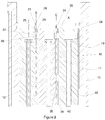
- the nuclear reactor 1 comprises a substantially cup or pool- shaped vessel 2 and a closure structure 3 placed on top of the vessel 2; the vessel 2 contains a core 4 and a hydraulic separation structure 5 delimiting a hot manifold 6 and a cold manifold 7 in which a primary cooling fluid F of the core 4 circulates.
- the primary fluid F has a free surface that in normal operation of the reactor 1 is at different levels H1 and H2 in the manifolds 6 and 7.
- the vessel 2 houses circulating pumps 8 for the primary fluid F, heat exchangers 9 through which the primary fluid F passes and which transfer the power generated in the core 4 to a secondary fluid, as well as other known components that are not shown.
- the hydraulic separation structure 5 preferably has an amphora-like shape, according to the solution known from patent application GE 2015A0000036 , and is suspended from the closure structure 3 of the vessel 2.
- an anchoring structure 11 for the fuel elements 12 is inserted inside the upper part 10 of the hydraulic separation structure 5.
- the fuel elements 12 extend along respective longitudinal and parallel axes (A) and have respective active parts 13 and respective service parts 14, which comprise a foot 15 and a head 16, respectively at the bottom and the top, and a connection shaft 17 between the active part 13 and the head 16.
- the shaft 17 possesses a certain amount of mechanical flexibility and is inserted with its upper portion 18 in an empty cylindrical volume inside the head 16 of the fuel element 4.
- This upper portion 18 is mechanically coupled to the head 16 by a spherical coupling 19, not described in detail as it is current technology, located at its top end.
- the feet 15 of the fuel elements 12 are in contact with each other and, as a whole, constitute a bundle that is radially constrained by the inner rim 20 of the opening 21 on the bottom of the hydraulic separation structure 5.
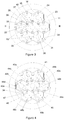
- the head 16 of the fuel element 12 houses support devices 22, in particular two vertical support devices 23, close to two opposite corners of the hexagonal section of the head 16, and two horizontal support devices 24, close to another two opposite corners of the head 16.
- the vertical support devices 23 are constituted by a substantially cylindrical main body 25 with the bottom end connected by a pin 26 to a vertically locking hollow cylindrical element 27.
- the main body 25 of the support element terminates at the top with a hexagonal head 28 and comprises a latch 29.
- the vertical support devices 23 can rotate approximately 90° about their own axis B, to move to a closed position 30 in which their projection on a horizontal plane is entirely contained inside the projection 31 of the head 16 of the fuel element 12, or to an open position 32, shown by all the other vertical support devices 23 in Figure 2 , in which the latch 29 protrudes for the projection 31 of the head 16 of the fuel element 12 it belong to, bringing its tip 33 over the adjacent fuel element 12 or, as regards the peripheral devices of peripheral fuel elements 12 of the core, engaging a slot 34 made in the anchoring structure 11 of the fuel elements 12.
- the vertical support devices 23 belonging to the fuel element 12 in open position 32 prevent downwards movement of the fuel element 12 that, with said latches 29 open, rests on the adjacent fuel elements 12.
- the vertical support devices 23 that project out from adjacent fuel elements 12 over a given fuel element 12 prevent upward movement of that fuel element 12.
- the core 4 appears to be a single block in which no fuel element 12 can move up or down with respect to the others. Furthermore, the vertical support devices 23 that are in a peripheral position of the core and in the open position, and which engage with the slots 34 in the anchoring structure 11 of the fuel elements 12, prevent vertical movement of the entire core 4.
- the horizontal support devices 24 are also of a substantially cylindrical shape and are characterized by at least two cams 35 and can rotate more than 90° about their own axis C, from a closed position 36, in which their projection on a horizontal plane is entirely contained inside the projection 31 of the head 16 of the fuel element 12, to an open position 37, shown by all the other horizontal support devices 24 in Figure 3 , in which the cam 35 protrudes from said projection 31 to bring an end tip 38 past the gap 39 between the heads 16 of the fuel elements 12, up to make contact with two heads 16, in particular contact with one of their faces 40 or, as regards the peripheral fuel elements 12, contact with the anchoring structure 11 of the fuel elements 12.
- the vertical support devices 23 perform the described vertical constraint function of the fuel elements, and the horizontal support devices 24 perform, as a whole, the radial constraint function of the heads 16 of the fuel elements when a gap 39 is provided between them.
- the core appears as a single block anchored vertically and radially to the anchoring structure 11.
- the extraction of a generic internal fuel element 41 of the core can be performed: (i) upon closing the two vertical support devices 42a and 42b belonging to adjacent fuel elements, (ii) upon closing the two horizontal support devices 43a and 43b belonging to the fuel element 41 in question, and (iii) upon closing the four support devices 44a, 44b, 44c and 44d belonging to four adjacent elements.
- the extraction of a generic external fuel element 45 of the core can be performed: (i) upon closing a vertical support device 46 belonging to an adjacent element, (ii) upon closing its own vertical support device 47 that is engaged in the slot 34 made in the support structure 11 of the fuel elements 12, (iii) upon closing the two horizontal support devices 48a and 48b belonging to the fuel element 45 in question, and (iv) upon closing the two horizontal support devices 49a and 49b belonging to two adjacent elements.
- the rotation limits for closing and opening the horizontal support devices 24 can be determined from the shape of the slots 34 occupied by the latches on the head 16 of the elements 12.
- the opening and closing of the support devices 22 can be performed by acting on the hexagonal head 28 via the grippers of the fuel transfer machine or via a specially provided device or remote manipulator, not shown because part of normal technology.
- Support for fuel elements 12 can be implemented with the use of just two vertical support devices 23 for each fuel element 12, preferably placed close to the centre line of two opposite sides 53 of the head 16; the support structure 11 may also provide a hydraulic separation function between hot manifold 6 and cold manifold 7.
- the replacement of a generic fuel element 41 inside the core is performed upon closing two vertical support devices 54a and 54b, respectively belonging to adjacent elements 12.
- the replacement of a generic fuel element 55 located on the periphery of the core is performed: (i) upon closing a vertical support device 56 belonging to an adjacent fuel element 12, and (ii) upon closing its own vertical support device 57 that is engaged in the slot 34 made in the support structure 11 of the fuel elements 12.
- expanders 57 characterized by an increased capacity of radial expansion with temperature and of which an embodiment is shown in Figure 7 , are applied to the shaft 17 of the fuel elements 12.
- Each shaft 17 is fitted with six expanders 57, each extending perpendicular to a respective face 58 of the fuel element 12.
- Each expander 57 which is symmetrical with respect to a centreline plane ⁇ perpendicular to the shaft 17 for improved structural performance, is constituted by a plurality of Z-shaped section low thermal expansion elements 59, alternating with high thermal expansion elements 60 of parallelepiped shape.
- the U-shaped closing element 61 is also made of a material with a high coefficient of thermal expansion, with two bolts 63 axially constraining the elements constituting the expander 57 and preventing disassembly.
- the shaft 17 is provided with a radial extension 64 on which the radial tip 65 of the innermost element 59 engages, on the inner radial end of which an element 60 engages, on the outer radial end of which a second element 59 engages in turn, and so on.
- elements 60 expand more than the structurally adjacent element 59 closer to the plane of symmetry, giving rise to a differential radial displacement of the radial tips of elements 60, which accumulates for each pair of elements 59 and 60 up to a resulting radial displacement ⁇ .
- the bolts 63 engage the closing element 61 with precision, while to allow the radial expansion of the expander 57, they engage with the other elements 59 and 60 and with the radial extension 64 with gradually increasing play as the plane of symmetry ⁇ is approached.
- the elastic element 66 inserted in a slot of the radial extension 64 and acting on a bolt 63 enables the radial recompaction of the expander 57 as the temperature drops.
- the expanders are mounted so as keep their projection inside the horizontal projection of the space occupied by the head 16 of the fuel elements 12 when cold, and to protrude from said projection only at high temperature when they perform their function.
- the heads 16 of the fuel elements 12 are practically isothermal with the support structure 11 because they are immersed in the same blanket gas 50 of the reactor above level H1 of the primary coolant F and therefore always held rigidly in position.
- the feet 15 of the fuel elements are at the temperature of the cold manifold 7 and at the same temperature as the inner rim 20 of the opening 21 of the hydraulic separation structure 5, and can therefore be mounted with close tolerances.
- the fuel element is axially and radially constrained at the top and free to thermally expand downwards. As the power increases, the fuel element expands radially more at the grid 51 than at the foot 15.
- This differential expansion accumulates from the centre towards the outside of the core and is made possible: (i) by rotation of the foot 15 about its radial constraints constituted by the point of contact 67 with the feet of adjacent elements and/or with the inner rim 20 of the opening 21, (ii) by rotation of the shaft 17 of the fuel element 12 with respect to the head 16 by means of the spherical coupling 19, and (iii) by flexure of the shaft 17.
- This differential expansion can be amplified up to a predetermined value ⁇ for activation of the expanders 57.
- the action of the expanders 57 is countered by elastic elements that return the core to the compact configuration when, by cooling, the action of the expanders 57 terminates.
- the elastic element is constituted by the shaft 17 of the fuel element 12; in the case of a rigid fuel element, the radial elastic element could be constituted by the support structure 11, or by elastic return elements, not shown, interposed between the heads 16 of the fuel elements 12.
- the shaft 17 is hollow, with a substantially tubular shape, and hydraulically connected to a tubular structure 68 that extends centrally for the entire active part 13 of the fuel elements 12.
- the tubular structure 68 is characterized by a plurality of small holes 70 along the length corresponding to the active part 13 of the fuel element.
- the tubular structure 68 is conveniently closed at the bottom by a threaded coupling with a plug 71 that, together with a shoulder 72 made on the tubular structure 68, constitutes the locking system of the lower grid 73 of the fuel element 12.
Landscapes
- Physics & Mathematics (AREA)
- Engineering & Computer Science (AREA)
- Plasma & Fusion (AREA)
- General Engineering & Computer Science (AREA)
- High Energy & Nuclear Physics (AREA)
- Structure Of Emergency Protection For Nuclear Reactors (AREA)
- Monitoring And Testing Of Nuclear Reactors (AREA)
Claims (13)
- Kernreaktor (1), aufweisend einen Behälter (2), der einen Kern (4) beherbergt, der ein Bündel von Brennstoffelementen (12) aufweist und in ein primäres Kühlfluid (F) des Kerns (4) eingetaucht ist; wobei
die Brennstoffelemente (12) sich entlang jeweiligen longitudinalen und parallelen Achsen (A) erstrecken und von jeweiligen Köpfen (16) mechanisch getragen werden, die miteinander verbunden und mit einer Verankerungsstruktur (11) durch Trägervorrichtungen (22) verbunden sind, die zwischen benachbarten Brennstoffelementen (12) wirken oder zwischen Brennstoffelementen (12), die auf dem Umfang des Kerns (4) gelegen sind, und der Verankerungsstruktur (11) wirken,
dadurch gekennzeichnet, dass
die Trägervorrichtungen (22) einen integralen Teil der Köpfe (16) der Brennstoffelemente (12) bilden. - Kernreaktor nach Anspruch 1, wobei die Trägervorrichtungen (22) im Wesentlichen zylindrische vertikale Trägervorrichtungen (23) aufweisen, die mit einem Riegel (29) versehen sind, mit der Möglichkeit zur Drehung um dessen vertikale Achse (B), um den Riegel (29) in einer geschlossenen Stellung zu halten, innerhalb des horizontalen Raums (31), der vom Kopf (16) des Brennstoffelements (12) eingenommen wird, oder die Spitze (33) der Riegel (29) in eine offene Stellung über dem Kopf (16) benachbarter Brennstoffelemente (12) oder in einen in der Verankerungsstruktur (11) ausgebildeten Schlitz (34) zu bewegen.
- Kernreaktor nach Anspruch 1, wobei die Trägervorrichtungen (22) im Wesentlichen zylindrische horizontale Trägervorrichtungen (24) aufweisen, die mit einer Vielzahl von Nocken (35) versehen sind, mit der Möglichkeit zur Drehung um ihre longitudinale Achse (C), um die Nocken (35) in einer geschlossenen Stellung innerhalb des horizontalen Raums (31) zu halten, der vom Kopf (16) der Brennstoffelemente (12) eingenommen wird, oder die Spitze (38) der Nocken (35) in eine offene Stellung in Kontakt mit dem Kopf (16) von zwei benachbarten Brennstoffelementen (12) oder in Kontakt mit der Oberfläche der Verankerungsstruktur (11) zu bewegen.
- Kernreaktor nach Anspruch 1, wobei die Trägervorrichtungen (22) vertikale Trägervorrichtungen (23) und horizontale Trägervorrichtungen (24) aufweisen; und wobei es möglich ist, die Operation eines Brennstoffaustauschs nach Schließen aller Trägervorrichtungen (22), die auf das auszutauschende Brennstoffelement (12) wirken und zu benachbarten Brennstoffelementen (12) gehören, nach Schließen der horizontalen Trägervorrichtungen (24) des auszutauschenden Brennstoffelements (12) und im Hinblick auf die peripheren Brennstoffelemente (12) des Kerns auch nach Schließen der vertikalen Trägervorrichtungen (23) des auszutauschenden Elements (12), welche mit den Schlitzen (34) der Verankerungsstruktur (11) zusammenwirken, durchzuführen.
- Kernreaktor nach Anspruch 4, wobei es möglich ist, während der Operation eines Brennstoffaustauschs die Brennstoffelemente (12) vertikal zu positionieren, indem sie auf den Köpfen (16) benachbarter Brennstoffelemente (12) mittels der vertikalen Trägervorrichtungen (23) in der offenen Stellung des zu positionierenden Brennstoffelements (12) abgestützt werden.
- Kernreaktor nach einem der vorhergehenden Ansprüche, wobei das Brennstoffelement (12) mit einem biegsamen Schaft (17) versehen ist, der einen oberen Teilbereich (18) aufweist, der in ein leeres zylindrisches Volumen innerhalb des Kopfes (16) des Brennstoffelements (12) eingesetzt ist, und mittels einer sphärischen Kopplung (19) mit seinem oberen Teilbereich (18) mit dem Kopf (16) mechanisch gekoppelt ist.
- Kernreaktor nach einem der vorhergehenden Ansprüche, wobei die Füße (15) der Brennstoffelemente (12) miteinander in Kontakt sind und durch einen Kontakt mit einem Innenrand (20) einer Öffnung (21) im unteren Teil der hydraulischen Trennstruktur (5) in kompakter Form gehalten werden.
- Kernreaktor nach einem der vorhergehenden Ansprüche, wobei eine Vielzahl von Expandiervorrichtungen (57), die auf jeweiligen Schäften (17) der Brennstoffelemente (12) positioniert sind, eine Expansion des Kerns herbeiführt, wenn eine vorbestimmte Temperatur überschritten wird.
- Kernreaktor nach Anspruch 8, wobei die Expandiervorrichtungen erhalten werden, indem Elemente (59) mit geringer Wärmeausdehnung abwechselnd mit Elementen (60) mit hoher Wärmeausdehnung gekoppelt werden.
- Kernreaktor nach Anspruch 7, wobei eine Expansion des Kerns (4) durch die Drehung der Füße (15) der Brennstoffelemente (12) um radiale Einschränkungen, die von den jeweiligen Punkten eines Kontakts (67) mit den Füßen (15) benachbarter Elemente und/oder mit dem Innenrand (20) der Öffnung (21) gebildet werden, durch die Drehung des Schafts (17) des Brennstoffelements (12) in Bezug auf den Kopf (16) mittels der sphärischen Kopplung (19) und durch die Biegung des Schafts (17) ermöglicht wird.
- Kernreaktor nach Anspruch 6, wobei der Schaft (17) hohl ist, mit einer im Wesentlichen rohrförmigen Form, und an seinem unteren Ende mit einer rohrförmigen Struktur (68) hydraulisch verbunden ist, die sich mittig über den gesamten aktiven Teil (13) der Brennstoffelemente (12) erstreckt; wobei die rohrförmige Struktur (68) am unteren Ende (69) hydraulisch abgedichtet ist und entlang der dem aktiven Teil (13) des Brennstoffelements (12) entsprechenden Länge mit einer Vielzahl von Löchern (70) versehen ist.
- Kernreaktor nach Anspruch 11, wobei das untere Ende mit einem reduzierten Durchmesser der rohrförmigen Struktur (68) durch einen Stöpsel (71) verschlossen ist, der zusammen mit einer Schulter (72), die auf der rohrförmigen Struktur (68) ausgebildet ist, wo ihr Durchmesser reduziert ist, das Verriegelungssystem des unteren Gitters (73) des Brennstoffelements (12) bildet.
- Kernreaktor nach Anspruch 11, wobei es über eine hydraulisch abgedichtete Kopplung zwischen den Greifern der Maschine für den Brennstoffaustausch mit dem Kopf (16) des Brennstoffelements (12) möglich ist, Kühlgas durch die Löcher (70) der rohrförmigen Struktur (68) und innerhalb des aktiven Teils (13) der Brennstoffelemente (12) während Operationen eines Brennstoffaustauschs einzuleiten.
Priority Applications (1)
| Application Number | Priority Date | Filing Date | Title |
|---|---|---|---|
| PL17732562T PL3469596T3 (pl) | 2016-05-04 | 2017-05-04 | Reaktor jądrowy z rdzeniem samonośnym |
Applications Claiming Priority (2)
| Application Number | Priority Date | Filing Date | Title |
|---|---|---|---|
| ITUA2016A003713A ITUA20163713A1 (it) | 2016-05-04 | 2016-05-04 | Reattore nucleare con nocciolo autoportante |
| PCT/IB2017/052606 WO2017191593A1 (en) | 2016-05-04 | 2017-05-04 | Nuclear reactor with a self-supporting core |
Publications (2)
| Publication Number | Publication Date |
|---|---|
| EP3469596A1 EP3469596A1 (de) | 2019-04-17 |
| EP3469596B1 true EP3469596B1 (de) | 2020-04-15 |
Family
ID=56853767
Family Applications (1)
| Application Number | Title | Priority Date | Filing Date |
|---|---|---|---|
| EP17732562.8A Active EP3469596B1 (de) | 2016-05-04 | 2017-05-04 | Kernreaktor mit einem selbsttragenden kern |
Country Status (13)
| Country | Link |
|---|---|
| US (1) | US11227694B2 (de) |
| EP (1) | EP3469596B1 (de) |
| JP (1) | JP7032382B2 (de) |
| KR (1) | KR102394260B1 (de) |
| CN (1) | CN109416946B (de) |
| ES (1) | ES2800331T3 (de) |
| HU (1) | HUE051228T2 (de) |
| IT (1) | ITUA20163713A1 (de) |
| MX (1) | MX393029B (de) |
| PL (1) | PL3469596T3 (de) |
| RU (1) | RU2730589C2 (de) |
| SA (1) | SA518400366B1 (de) |
| WO (1) | WO2017191593A1 (de) |
Families Citing this family (6)
| Publication number | Priority date | Publication date | Assignee | Title |
|---|---|---|---|---|
| CN111477364B (zh) * | 2020-02-27 | 2022-07-01 | 中国原子能科学研究院 | 核反应堆组件 |
| US11798697B2 (en) | 2020-08-17 | 2023-10-24 | Terrapower, Llc | Passive heat removal system for nuclear reactors |
| CN113658725B (zh) | 2020-12-01 | 2024-08-20 | 国家电投集团科学技术研究院有限公司 | 核反应堆 |
| MX2023014035A (es) * | 2021-05-31 | 2023-12-15 | Copenhagen Atomics As | Nucleo de reactor nuclear de sal fundida y metodo para operar tal nucleo de reactor nuclear. |
| IT202200012476A1 (it) * | 2022-06-13 | 2023-12-13 | Newcleo Ltd | Reattore nucleare provvisto di un sistema di supporto del nocciolo |
| CN116110623B (zh) * | 2022-12-16 | 2024-01-26 | 国科中子能(青岛)研究院有限公司 | 一种超紧凑反应堆系统 |
Family Cites Families (21)
| Publication number | Priority date | Publication date | Assignee | Title |
|---|---|---|---|---|
| US3014856A (en) * | 1957-10-22 | 1961-12-26 | Allis Chalmers Mfg Co | Locking device for reactor fuel elements containing an interlocking feature |
| US3398050A (en) * | 1966-01-07 | 1968-08-20 | Atomic Power Dev Ass Inc | Nuclear reactor system |
| FR1552306A (de) * | 1966-12-23 | 1969-01-03 | ||
| US3661708A (en) * | 1968-05-09 | 1972-05-09 | Atomic Power Dev Ass Inc | Fuel subassembly for nuclear reactor |
| GB1519546A (en) * | 1975-10-02 | 1978-08-02 | Commissariat Energie Atomique | Nuclear reactor |
| US4131510A (en) * | 1977-06-21 | 1978-12-26 | The United States Of America As Represented By The United States Department Of Energy | Magnetic nuclear core restraint and control |
| FR2609833B1 (fr) * | 1987-01-21 | 1991-10-18 | Novatome | Coeur d'un reacteur nucleaire et procede de chargement de ce coeur |
| WO1990003647A1 (de) * | 1988-09-30 | 1990-04-05 | Siemens Aktiengesellschaft | Anordnung zum zentrieren von bauteilen eines kernreaktors |
| JPH02151791A (ja) | 1988-12-05 | 1990-06-11 | Power Reactor & Nuclear Fuel Dev Corp | 分散型高速増殖炉の蒸気発生器 |
| JP2740995B2 (ja) | 1992-07-29 | 1998-04-15 | 動力炉・核燃料開発事業団 | 液体金属冷却型高速炉及びそれを用いた発電システム |
| US5683216A (en) * | 1995-02-02 | 1997-11-04 | General Electric Company | Spring latching mechanisms for preventing relative movement of assembled components |
| SE508875C2 (sv) * | 1997-03-11 | 1998-11-09 | Asea Atom Ab | Anordning och förfarande för låsning av stavar i bottenplattan på en bränslepatron |
| RU2216056C2 (ru) * | 2001-09-06 | 2003-11-10 | Открытое акционерное общество "Новосибирский завод химконцентратов" | Тепловыделяющая сборка и активная зона водо-водяного ядерного реактора |
| EP2248133B1 (de) * | 2007-09-26 | 2011-08-31 | Del Nova Vis S.R.L. | Kernreaktor, insbesondere kernreaktor des pool-typs mit brennstoffelementen neuen konzepts |
| RU2448376C1 (ru) * | 2010-10-01 | 2012-04-20 | Открытое акционерное общество "Машиностроительный завод" | Структура пластинчатой решетки для тепловыделяющей сборки |
| WO2012097029A1 (en) * | 2011-01-14 | 2012-07-19 | Thorium Power, Inc. | Locking device for nuclear fuel sub-assemblies |
| FR2998822B1 (fr) * | 2012-12-04 | 2015-02-20 | Commissariat Energie Atomique | Systeme de prehension et de verrouillage/deverrouillage, application a la manutention de porte echantillon de materiaux nucleaires |
| RU2551432C1 (ru) * | 2013-11-19 | 2015-05-27 | Открытое Акционерное Общество "Акмэ-Инжиниринг" | Оболочка для тепловыделяющего элемента, тепловыделяющий элемент и тепловыделяющая сборка |
| RU2545098C1 (ru) * | 2014-01-31 | 2015-03-27 | Российская Федерация, от имени которой выступает Государственная корпорация по атомной энергии "Росатом" | Реакторная установка с реактором на быстрых нейтронах и свинцовым теплоносителем |
| RU2576024C2 (ru) * | 2014-04-02 | 2016-02-27 | Акционерное общество "Центральное конструкторское бюро машиностроения" (АО "ЦКБМ") | Тепловыделяющая сборка |
| RU159627U1 (ru) * | 2015-08-24 | 2016-02-20 | Российская Федерация, от имени которой выступает Государственная корпорация по атомной энергии "Росатом" | Опорная решетка тепловыделяющих элементов высокотемпературного ядерного реактора космической энергетической установки |
-
2016
- 2016-05-04 IT ITUA2016A003713A patent/ITUA20163713A1/it unknown
-
2017
- 2017-05-04 CN CN201780027903.0A patent/CN109416946B/zh active Active
- 2017-05-04 JP JP2019510487A patent/JP7032382B2/ja active Active
- 2017-05-04 WO PCT/IB2017/052606 patent/WO2017191593A1/en not_active Ceased
- 2017-05-04 HU HUE17732562A patent/HUE051228T2/hu unknown
- 2017-05-04 US US16/097,472 patent/US11227694B2/en active Active
- 2017-05-04 EP EP17732562.8A patent/EP3469596B1/de active Active
- 2017-05-04 RU RU2018137997A patent/RU2730589C2/ru active
- 2017-05-04 MX MX2018013291A patent/MX393029B/es unknown
- 2017-05-04 PL PL17732562T patent/PL3469596T3/pl unknown
- 2017-05-04 KR KR1020187034324A patent/KR102394260B1/ko active Active
- 2017-05-04 ES ES17732562T patent/ES2800331T3/es active Active
-
2018
- 2018-11-04 SA SA518400366A patent/SA518400366B1/ar unknown
Non-Patent Citations (1)
| Title |
|---|
| None * |
Also Published As
| Publication number | Publication date |
|---|---|
| ES2800331T3 (es) | 2020-12-29 |
| EP3469596A1 (de) | 2019-04-17 |
| CN109416946A (zh) | 2019-03-01 |
| RU2018137997A3 (de) | 2020-06-18 |
| KR102394260B1 (ko) | 2022-05-04 |
| KR20190015249A (ko) | 2019-02-13 |
| CN109416946B (zh) | 2023-06-09 |
| RU2018137997A (ru) | 2020-06-04 |
| PL3469596T3 (pl) | 2020-11-02 |
| HUE051228T2 (hu) | 2021-03-01 |
| US11227694B2 (en) | 2022-01-18 |
| RU2730589C2 (ru) | 2020-08-24 |
| ITUA20163713A1 (it) | 2017-11-04 |
| US20190189296A1 (en) | 2019-06-20 |
| JP2019515319A (ja) | 2019-06-06 |
| WO2017191593A1 (en) | 2017-11-09 |
| CA3022362A1 (en) | 2017-11-09 |
| MX2018013291A (es) | 2019-08-05 |
| SA518400366B1 (ar) | 2022-07-19 |
| JP7032382B2 (ja) | 2022-03-08 |
| MX393029B (es) | 2025-03-24 |
Similar Documents
| Publication | Publication Date | Title |
|---|---|---|
| EP3469596B1 (de) | Kernreaktor mit einem selbsttragenden kern | |
| US4342721A (en) | Fast nuclear reactor | |
| EP2248133B1 (de) | Kernreaktor, insbesondere kernreaktor des pool-typs mit brennstoffelementen neuen konzepts | |
| Beck et al. | Conceptual design of ASTRID fuel sub-assemblies | |
| US12217877B2 (en) | Liquid metal cooled nuclear reactor incorporating a fully passive decay heat removal system with a modular cold source | |
| FI20206180A1 (en) | Nuclear reactor module and a nuclear nuclear thermal reactor comprising the same and a method for operating the nuclear reactor module | |
| US3293139A (en) | Prestressed concrete pressure vessel for nuclear reactors | |
| CA3022362C (en) | Nuclear reactor with self-supporting core | |
| US11195630B2 (en) | Nuclear reactor with fuel elements provided with expanders | |
| EP3683801B1 (de) | Steuerstab-führungsrohr mit verlängertem führungseinsatz | |
| US20050069079A1 (en) | Modular reactor containment system | |
| CN115938620B (zh) | 包括具有模块化冷源的完全非能动衰变热排出(dhr)系统的液态金属冷却核反应堆 | |
| WO2023242727A1 (en) | Nuclear reactor provided with a core support system | |
| EP2839485B1 (de) | Steuerstabführungseinheit für kleine modulare reaktoren | |
| Bagdasarov et al. | Concept for fast-response actuation facility for passive emergency protection | |
| ITMI20071856A1 (it) | Reattore nucleare, in particolare reattore nucleare a piscina, con elementi di combustibile di nuova concezione |
Legal Events
| Date | Code | Title | Description |
|---|---|---|---|
| STAA | Information on the status of an ep patent application or granted ep patent |
Free format text: STATUS: UNKNOWN |
|
| STAA | Information on the status of an ep patent application or granted ep patent |
Free format text: STATUS: THE INTERNATIONAL PUBLICATION HAS BEEN MADE |
|
| PUAI | Public reference made under article 153(3) epc to a published international application that has entered the european phase |
Free format text: ORIGINAL CODE: 0009012 |
|
| STAA | Information on the status of an ep patent application or granted ep patent |
Free format text: STATUS: REQUEST FOR EXAMINATION WAS MADE |
|
| 17P | Request for examination filed |
Effective date: 20181109 |
|
| AK | Designated contracting states |
Kind code of ref document: A1 Designated state(s): AL AT BE BG CH CY CZ DE DK EE ES FI FR GB GR HR HU IE IS IT LI LT LU LV MC MK MT NL NO PL PT RO RS SE SI SK SM TR |
|
| AX | Request for extension of the european patent |
Extension state: BA ME |
|
| DAV | Request for validation of the european patent (deleted) | ||
| DAX | Request for extension of the european patent (deleted) | ||
| GRAP | Despatch of communication of intention to grant a patent |
Free format text: ORIGINAL CODE: EPIDOSNIGR1 |
|
| STAA | Information on the status of an ep patent application or granted ep patent |
Free format text: STATUS: GRANT OF PATENT IS INTENDED |
|
| INTG | Intention to grant announced |
Effective date: 20191021 |
|
| GRAJ | Information related to disapproval of communication of intention to grant by the applicant or resumption of examination proceedings by the epo deleted |
Free format text: ORIGINAL CODE: EPIDOSDIGR1 |
|
| STAA | Information on the status of an ep patent application or granted ep patent |
Free format text: STATUS: REQUEST FOR EXAMINATION WAS MADE |
|
| GRAR | Information related to intention to grant a patent recorded |
Free format text: ORIGINAL CODE: EPIDOSNIGR71 |
|
| GRAS | Grant fee paid |
Free format text: ORIGINAL CODE: EPIDOSNIGR3 |
|
| STAA | Information on the status of an ep patent application or granted ep patent |
Free format text: STATUS: GRANT OF PATENT IS INTENDED |
|
| GRAA | (expected) grant |
Free format text: ORIGINAL CODE: 0009210 |
|
| STAA | Information on the status of an ep patent application or granted ep patent |
Free format text: STATUS: THE PATENT HAS BEEN GRANTED |
|
| INTC | Intention to grant announced (deleted) | ||
| AK | Designated contracting states |
Kind code of ref document: B1 Designated state(s): AL AT BE BG CH CY CZ DE DK EE ES FI FR GB GR HR HU IE IS IT LI LT LU LV MC MK MT NL NO PL PT RO RS SE SI SK SM TR |
|
| INTG | Intention to grant announced |
Effective date: 20200306 |
|
| REG | Reference to a national code |
Ref country code: CH Ref legal event code: EP |
|
| REG | Reference to a national code |
Ref country code: CH Ref legal event code: NV Representative=s name: HEPP WENGER RYFFEL AG, CH |
|
| REG | Reference to a national code |
Ref country code: DE Ref legal event code: R096 Ref document number: 602017014865 Country of ref document: DE |
|
| REG | Reference to a national code |
Ref country code: IE Ref legal event code: FG4D |
|
| REG | Reference to a national code |
Ref country code: AT Ref legal event code: REF Ref document number: 1258237 Country of ref document: AT Kind code of ref document: T Effective date: 20200515 |
|
| REG | Reference to a national code |
Ref country code: SE Ref legal event code: TRGR |
|
| REG | Reference to a national code |
Ref country code: NL Ref legal event code: MP Effective date: 20200415 |
|
| REG | Reference to a national code |
Ref country code: LT Ref legal event code: MG4D |
|
| PG25 | Lapsed in a contracting state [announced via postgrant information from national office to epo] |
Ref country code: NL Free format text: LAPSE BECAUSE OF FAILURE TO SUBMIT A TRANSLATION OF THE DESCRIPTION OR TO PAY THE FEE WITHIN THE PRESCRIBED TIME-LIMIT Effective date: 20200415 Ref country code: PT Free format text: LAPSE BECAUSE OF FAILURE TO SUBMIT A TRANSLATION OF THE DESCRIPTION OR TO PAY THE FEE WITHIN THE PRESCRIBED TIME-LIMIT Effective date: 20200817 Ref country code: LT Free format text: LAPSE BECAUSE OF FAILURE TO SUBMIT A TRANSLATION OF THE DESCRIPTION OR TO PAY THE FEE WITHIN THE PRESCRIBED TIME-LIMIT Effective date: 20200415 Ref country code: FI Free format text: LAPSE BECAUSE OF FAILURE TO SUBMIT A TRANSLATION OF THE DESCRIPTION OR TO PAY THE FEE WITHIN THE PRESCRIBED TIME-LIMIT Effective date: 20200415 Ref country code: GR Free format text: LAPSE BECAUSE OF FAILURE TO SUBMIT A TRANSLATION OF THE DESCRIPTION OR TO PAY THE FEE WITHIN THE PRESCRIBED TIME-LIMIT Effective date: 20200716 Ref country code: NO Free format text: LAPSE BECAUSE OF FAILURE TO SUBMIT A TRANSLATION OF THE DESCRIPTION OR TO PAY THE FEE WITHIN THE PRESCRIBED TIME-LIMIT Effective date: 20200715 Ref country code: IS Free format text: LAPSE BECAUSE OF FAILURE TO SUBMIT A TRANSLATION OF THE DESCRIPTION OR TO PAY THE FEE WITHIN THE PRESCRIBED TIME-LIMIT Effective date: 20200815 |
|
| REG | Reference to a national code |
Ref country code: AT Ref legal event code: MK05 Ref document number: 1258237 Country of ref document: AT Kind code of ref document: T Effective date: 20200415 |
|
| PG25 | Lapsed in a contracting state [announced via postgrant information from national office to epo] |
Ref country code: BG Free format text: LAPSE BECAUSE OF FAILURE TO SUBMIT A TRANSLATION OF THE DESCRIPTION OR TO PAY THE FEE WITHIN THE PRESCRIBED TIME-LIMIT Effective date: 20200715 Ref country code: RS Free format text: LAPSE BECAUSE OF FAILURE TO SUBMIT A TRANSLATION OF THE DESCRIPTION OR TO PAY THE FEE WITHIN THE PRESCRIBED TIME-LIMIT Effective date: 20200415 Ref country code: HR Free format text: LAPSE BECAUSE OF FAILURE TO SUBMIT A TRANSLATION OF THE DESCRIPTION OR TO PAY THE FEE WITHIN THE PRESCRIBED TIME-LIMIT Effective date: 20200415 Ref country code: LV Free format text: LAPSE BECAUSE OF FAILURE TO SUBMIT A TRANSLATION OF THE DESCRIPTION OR TO PAY THE FEE WITHIN THE PRESCRIBED TIME-LIMIT Effective date: 20200415 |
|
| PG25 | Lapsed in a contracting state [announced via postgrant information from national office to epo] |
Ref country code: AL Free format text: LAPSE BECAUSE OF FAILURE TO SUBMIT A TRANSLATION OF THE DESCRIPTION OR TO PAY THE FEE WITHIN THE PRESCRIBED TIME-LIMIT Effective date: 20200415 |
|
| REG | Reference to a national code |
Ref country code: DE Ref legal event code: R097 Ref document number: 602017014865 Country of ref document: DE |
|
| PG25 | Lapsed in a contracting state [announced via postgrant information from national office to epo] |
Ref country code: SM Free format text: LAPSE BECAUSE OF FAILURE TO SUBMIT A TRANSLATION OF THE DESCRIPTION OR TO PAY THE FEE WITHIN THE PRESCRIBED TIME-LIMIT Effective date: 20200415 Ref country code: EE Free format text: LAPSE BECAUSE OF FAILURE TO SUBMIT A TRANSLATION OF THE DESCRIPTION OR TO PAY THE FEE WITHIN THE PRESCRIBED TIME-LIMIT Effective date: 20200415 Ref country code: DK Free format text: LAPSE BECAUSE OF FAILURE TO SUBMIT A TRANSLATION OF THE DESCRIPTION OR TO PAY THE FEE WITHIN THE PRESCRIBED TIME-LIMIT Effective date: 20200415 Ref country code: AT Free format text: LAPSE BECAUSE OF FAILURE TO SUBMIT A TRANSLATION OF THE DESCRIPTION OR TO PAY THE FEE WITHIN THE PRESCRIBED TIME-LIMIT Effective date: 20200415 Ref country code: CZ Free format text: LAPSE BECAUSE OF FAILURE TO SUBMIT A TRANSLATION OF THE DESCRIPTION OR TO PAY THE FEE WITHIN THE PRESCRIBED TIME-LIMIT Effective date: 20200415 Ref country code: MC Free format text: LAPSE BECAUSE OF FAILURE TO SUBMIT A TRANSLATION OF THE DESCRIPTION OR TO PAY THE FEE WITHIN THE PRESCRIBED TIME-LIMIT Effective date: 20200415 |
|
| PLBE | No opposition filed within time limit |
Free format text: ORIGINAL CODE: 0009261 |
|
| STAA | Information on the status of an ep patent application or granted ep patent |
Free format text: STATUS: NO OPPOSITION FILED WITHIN TIME LIMIT |
|
| PG25 | Lapsed in a contracting state [announced via postgrant information from national office to epo] |
Ref country code: SK Free format text: LAPSE BECAUSE OF FAILURE TO SUBMIT A TRANSLATION OF THE DESCRIPTION OR TO PAY THE FEE WITHIN THE PRESCRIBED TIME-LIMIT Effective date: 20200415 |
|
| REG | Reference to a national code |
Ref country code: HU Ref legal event code: AG4A Ref document number: E051228 Country of ref document: HU |
|
| 26N | No opposition filed |
Effective date: 20210118 |
|
| PG25 | Lapsed in a contracting state [announced via postgrant information from national office to epo] |
Ref country code: LU Free format text: LAPSE BECAUSE OF NON-PAYMENT OF DUE FEES Effective date: 20200504 |
|
| PG25 | Lapsed in a contracting state [announced via postgrant information from national office to epo] |
Ref country code: IE Free format text: LAPSE BECAUSE OF NON-PAYMENT OF DUE FEES Effective date: 20200504 |
|
| PG25 | Lapsed in a contracting state [announced via postgrant information from national office to epo] |
Ref country code: SI Free format text: LAPSE BECAUSE OF FAILURE TO SUBMIT A TRANSLATION OF THE DESCRIPTION OR TO PAY THE FEE WITHIN THE PRESCRIBED TIME-LIMIT Effective date: 20200415 |
|
| REG | Reference to a national code |
Ref country code: DE Ref legal event code: R081 Ref document number: 602017014865 Country of ref document: DE Owner name: NEWCLEO LTD, GB Free format text: FORMER OWNER: CINOTTI, LUCIANO, RECCO, IT |
|
| PG25 | Lapsed in a contracting state [announced via postgrant information from national office to epo] |
Ref country code: TR Free format text: LAPSE BECAUSE OF FAILURE TO SUBMIT A TRANSLATION OF THE DESCRIPTION OR TO PAY THE FEE WITHIN THE PRESCRIBED TIME-LIMIT Effective date: 20200415 Ref country code: MT Free format text: LAPSE BECAUSE OF FAILURE TO SUBMIT A TRANSLATION OF THE DESCRIPTION OR TO PAY THE FEE WITHIN THE PRESCRIBED TIME-LIMIT Effective date: 20200415 Ref country code: CY Free format text: LAPSE BECAUSE OF FAILURE TO SUBMIT A TRANSLATION OF THE DESCRIPTION OR TO PAY THE FEE WITHIN THE PRESCRIBED TIME-LIMIT Effective date: 20200415 |
|
| REG | Reference to a national code |
Ref country code: GB Ref legal event code: 732E Free format text: REGISTERED BETWEEN 20220519 AND 20220525 |
|
| REG | Reference to a national code |
Ref country code: BE Ref legal event code: PD Owner name: NEWCLEO LTD; GB Free format text: DETAILS ASSIGNMENT: CHANGE OF OWNER(S), ASSIGNMENT; FORMER OWNER NAME: CINOTTI, LUCIANO Effective date: 20220527 |
|
| PG25 | Lapsed in a contracting state [announced via postgrant information from national office to epo] |
Ref country code: MK Free format text: LAPSE BECAUSE OF FAILURE TO SUBMIT A TRANSLATION OF THE DESCRIPTION OR TO PAY THE FEE WITHIN THE PRESCRIBED TIME-LIMIT Effective date: 20200415 |
|
| REG | Reference to a national code |
Ref country code: ES Ref legal event code: PC2A Owner name: NEWCLEO LTD Effective date: 20220901 |
|
| P01 | Opt-out of the competence of the unified patent court (upc) registered |
Effective date: 20230526 |
|
| REG | Reference to a national code |
Ref country code: HU Ref legal event code: GB9C Owner name: NEWCLEO LTD, GB Free format text: FORMER OWNER(S): CINOTTI, LUCIANO, IT Ref country code: HU Ref legal event code: FH1C Free format text: FORMER REPRESENTATIVE(S): DR. CSANYI BALAZS MIHALY UEGYVED, HU Representative=s name: DR. CSANYI BALAZS MIHALY UEGYVED, HU |
|
| PGFP | Annual fee paid to national office [announced via postgrant information from national office to epo] |
Ref country code: PL Payment date: 20250414 Year of fee payment: 9 Ref country code: DE Payment date: 20250528 Year of fee payment: 9 |
|
| PGFP | Annual fee paid to national office [announced via postgrant information from national office to epo] |
Ref country code: GB Payment date: 20250520 Year of fee payment: 9 Ref country code: ES Payment date: 20250612 Year of fee payment: 9 |
|
| PGFP | Annual fee paid to national office [announced via postgrant information from national office to epo] |
Ref country code: HU Payment date: 20250429 Year of fee payment: 9 |
|
| PGFP | Annual fee paid to national office [announced via postgrant information from national office to epo] |
Ref country code: BE Payment date: 20250526 Year of fee payment: 9 Ref country code: IT Payment date: 20250507 Year of fee payment: 9 |
|
| PGFP | Annual fee paid to national office [announced via postgrant information from national office to epo] |
Ref country code: FR Payment date: 20250526 Year of fee payment: 9 |
|
| PGFP | Annual fee paid to national office [announced via postgrant information from national office to epo] |
Ref country code: CH Payment date: 20250601 Year of fee payment: 9 |
|
| PGFP | Annual fee paid to national office [announced via postgrant information from national office to epo] |
Ref country code: RO Payment date: 20250425 Year of fee payment: 9 |
|
| PGFP | Annual fee paid to national office [announced via postgrant information from national office to epo] |
Ref country code: SE Payment date: 20250526 Year of fee payment: 9 |