EP3469574B1 - Synthetisches bild und verfahren zur herstellung davon - Google Patents
Synthetisches bild und verfahren zur herstellung davon Download PDFInfo
- Publication number
- EP3469574B1 EP3469574B1 EP17813689.1A EP17813689A EP3469574B1 EP 3469574 B1 EP3469574 B1 EP 3469574B1 EP 17813689 A EP17813689 A EP 17813689A EP 3469574 B1 EP3469574 B1 EP 3469574B1
- Authority
- EP
- European Patent Office
- Prior art keywords
- image
- synthetic
- image objects
- objects
- focusing element
- Prior art date
- Legal status (The legal status is an assumption and is not a legal conclusion. Google has not performed a legal analysis and makes no representation as to the accuracy of the status listed.)
- Active
Links
Images


Classifications
-
- G—PHYSICS
- G02—OPTICS
- G02B—OPTICAL ELEMENTS, SYSTEMS OR APPARATUS
- G02B30/00—Optical systems or apparatus for producing three-dimensional [3D] effects, e.g. stereoscopic images
- G02B30/20—Optical systems or apparatus for producing three-dimensional [3D] effects, e.g. stereoscopic images by providing first and second parallax images to an observer's left and right eyes
- G02B30/26—Optical systems or apparatus for producing three-dimensional [3D] effects, e.g. stereoscopic images by providing first and second parallax images to an observer's left and right eyes of the autostereoscopic type
- G02B30/27—Optical systems or apparatus for producing three-dimensional [3D] effects, e.g. stereoscopic images by providing first and second parallax images to an observer's left and right eyes of the autostereoscopic type involving lenticular arrays
-
- G—PHYSICS
- G02—OPTICS
- G02B—OPTICAL ELEMENTS, SYSTEMS OR APPARATUS
- G02B27/00—Optical systems or apparatus not provided for by any of the groups G02B1/00 - G02B26/00, G02B30/00
-
- G—PHYSICS
- G02—OPTICS
- G02B—OPTICAL ELEMENTS, SYSTEMS OR APPARATUS
- G02B27/00—Optical systems or apparatus not provided for by any of the groups G02B1/00 - G02B26/00, G02B30/00
- G02B27/10—Beam splitting or combining systems
-
- G—PHYSICS
- G02—OPTICS
- G02B—OPTICAL ELEMENTS, SYSTEMS OR APPARATUS
- G02B30/00—Optical systems or apparatus for producing three-dimensional [3D] effects, e.g. stereoscopic images
- G02B30/20—Optical systems or apparatus for producing three-dimensional [3D] effects, e.g. stereoscopic images by providing first and second parallax images to an observer's left and right eyes
- G02B30/34—Stereoscopes providing a stereoscopic pair of separated images corresponding to parallactically displaced views of the same object, e.g. 3D slide viewers
- G02B30/35—Stereoscopes providing a stereoscopic pair of separated images corresponding to parallactically displaced views of the same object, e.g. 3D slide viewers using reflective optical elements in the optical path between the images and the observer
-
- G—PHYSICS
- G02—OPTICS
- G02F—OPTICAL DEVICES OR ARRANGEMENTS FOR THE CONTROL OF LIGHT BY MODIFICATION OF THE OPTICAL PROPERTIES OF THE MEDIA OF THE ELEMENTS INVOLVED THEREIN; NON-LINEAR OPTICS; FREQUENCY-CHANGING OF LIGHT; OPTICAL LOGIC ELEMENTS; OPTICAL ANALOGUE/DIGITAL CONVERTERS
- G02F1/00—Devices or arrangements for the control of the intensity, colour, phase, polarisation or direction of light arriving from an independent light source, e.g. switching, gating or modulating; Non-linear optics
- G02F1/01—Devices or arrangements for the control of the intensity, colour, phase, polarisation or direction of light arriving from an independent light source, e.g. switching, gating or modulating; Non-linear optics for the control of the intensity, phase, polarisation or colour
- G02F1/13—Devices or arrangements for the control of the intensity, colour, phase, polarisation or direction of light arriving from an independent light source, e.g. switching, gating or modulating; Non-linear optics for the control of the intensity, phase, polarisation or colour based on liquid crystals, e.g. single liquid crystal display cells
- G02F1/133—Constructional arrangements; Operation of liquid crystal cells; Circuit arrangements
-
- G—PHYSICS
- G03—PHOTOGRAPHY; CINEMATOGRAPHY; ANALOGOUS TECHNIQUES USING WAVES OTHER THAN OPTICAL WAVES; ELECTROGRAPHY; HOLOGRAPHY
- G03B—APPARATUS OR ARRANGEMENTS FOR TAKING PHOTOGRAPHS OR FOR PROJECTING OR VIEWING THEM; APPARATUS OR ARRANGEMENTS EMPLOYING ANALOGOUS TECHNIQUES USING WAVES OTHER THAN OPTICAL WAVES; ACCESSORIES THEREFOR
- G03B21/00—Projectors or projection-type viewers; Accessories therefor
-
- G—PHYSICS
- G06—COMPUTING OR CALCULATING; COUNTING
- G06F—ELECTRIC DIGITAL DATA PROCESSING
- G06F1/00—Details not covered by groups G06F3/00 - G06F13/00 and G06F21/00
- G06F1/16—Constructional details or arrangements
- G06F1/1613—Constructional details or arrangements for portable computers
- G06F1/1633—Constructional details or arrangements of portable computers not specific to the type of enclosures covered by groups G06F1/1615 - G06F1/1626
- G06F1/1637—Details related to the display arrangement, including those related to the mounting of the display in the housing
-
- G—PHYSICS
- G06—COMPUTING OR CALCULATING; COUNTING
- G06T—IMAGE DATA PROCESSING OR GENERATION, IN GENERAL
- G06T3/00—Geometric image transformations in the plane of the image
- G06T3/40—Scaling of whole images or parts thereof, e.g. expanding or contracting
-
- G—PHYSICS
- G09—EDUCATION; CRYPTOGRAPHY; DISPLAY; ADVERTISING; SEALS
- G09F—DISPLAYING; ADVERTISING; SIGNS; LABELS OR NAME-PLATES; SEALS
- G09F19/00—Advertising or display means not otherwise provided for
- G09F19/12—Advertising or display means not otherwise provided for using special optical effects
- G09F19/14—Advertising or display means not otherwise provided for using special optical effects displaying different signs depending upon the view-point of the observer
-
- H—ELECTRICITY
- H04—ELECTRIC COMMUNICATION TECHNIQUE
- H04N—PICTORIAL COMMUNICATION, e.g. TELEVISION
- H04N23/00—Cameras or camera modules comprising electronic image sensors; Control thereof
- H04N23/60—Control of cameras or camera modules
- H04N23/67—Focus control based on electronic image sensor signals
-
- B—PERFORMING OPERATIONS; TRANSPORTING
- B42—BOOKBINDING; ALBUMS; FILES; SPECIAL PRINTED MATTER
- B42D—BOOKS; BOOK COVERS; LOOSE LEAVES; PRINTED MATTER CHARACTERISED BY IDENTIFICATION OR SECURITY FEATURES; PRINTED MATTER OF SPECIAL FORMAT OR STYLE NOT OTHERWISE PROVIDED FOR; DEVICES FOR USE THEREWITH AND NOT OTHERWISE PROVIDED FOR; MOVABLE-STRIP WRITING OR READING APPARATUS
- B42D25/00—Information-bearing cards or sheet-like structures characterised by identification or security features; Manufacture thereof
- B42D25/30—Identification or security features, e.g. for preventing forgery
- B42D25/342—Moiré effects
-
- B—PERFORMING OPERATIONS; TRANSPORTING
- B42—BOOKBINDING; ALBUMS; FILES; SPECIAL PRINTED MATTER
- B42D—BOOKS; BOOK COVERS; LOOSE LEAVES; PRINTED MATTER CHARACTERISED BY IDENTIFICATION OR SECURITY FEATURES; PRINTED MATTER OF SPECIAL FORMAT OR STYLE NOT OTHERWISE PROVIDED FOR; DEVICES FOR USE THEREWITH AND NOT OTHERWISE PROVIDED FOR; MOVABLE-STRIP WRITING OR READING APPARATUS
- B42D25/00—Information-bearing cards or sheet-like structures characterised by identification or security features; Manufacture thereof
- B42D25/30—Identification or security features, e.g. for preventing forgery
- B42D25/36—Identification or security features, e.g. for preventing forgery comprising special materials
-
- G—PHYSICS
- G09—EDUCATION; CRYPTOGRAPHY; DISPLAY; ADVERTISING; SEALS
- G09F—DISPLAYING; ADVERTISING; SIGNS; LABELS OR NAME-PLATES; SEALS
- G09F3/00—Labels, tag tickets, or similar identification or indication means; Seals; Postage or like stamps
- G09F3/02—Forms or constructions
Definitions
- the present invention relates in general to optical devices and manufacturing processes therefore, and in particular to synthetic-image devices and manufacturing methods therefore.
- Synthetic-image devices are today used for creating eye-catching visual effects for many different purposes, e.g. as security markings, tamper indications or simply as aesthetic images.
- the synthetic-image device is intended to be provided as a label or as an integrated part in another device.
- Many different optical effects have been discovered and used and often different optical effects are combined to give a certain requested visual appearance.
- a typical realization of a synthetic-image device is a thin polymer foil, where focusing elements and image objects are created in different planes.
- the typical approach for a synthetic-image device is to provide an array of small focusing element.
- the focusing element may be different kinds of lenses, apertures or reflectors.
- An image layer is provided with image objects.
- the image layer is provided relative to the array of focusing elements such that when the device is viewed from different angles, different parts of the image objects are enlarged by the focusing elements and together form an integral image.
- the synthetic image can change in different ways when the viewing conditions, e.g. viewing angles, are changed.
- the actual perception of the synthetic image is performed by the user's eyes and brain.
- the ability of the human brain to combine different part information into a totality converts the fragmented part images from the individual focusing elements into an understandable synthetic image. This ability to create an understandable totality can also be used for creating "surprising effect", which can be used as eye-catching features or for security and/or authentication purposes. However, the manner in which the brain correlates different fragments may in some cases result in unexpected difficulties to create an understandable totality.
- a micro-optic security and image presentation system includes an in-plane image formed of an array or pattern of image icons and an array of focusing elements.
- the system produces two different synthetic images whereby one synthetic image operates to modulate or control the extent of the appearance of another synthetic image.
- the array of image icons forms an in-plane synthetic image, while the interaction of the array of focusing elements with the array of image icons forms a separate synthetically magnified image that serves to control the field of view of the in-plane image and serves to modulate or control the extent of appearance of the in-plane image.
- the appearance of the in-plane image visually appears and disappears depending upon the viewing angle of the system.
- a general object with the herein presented technology is to improve the ability for interpretation of synthetic images.
- a synthetic-image device comprises an image layer and a focusing element array.
- the image layer is arranged in a vicinity of a focal distance of focusing elements of the focusing element array.
- the image layer comprises composite image objects.
- the composite image objects of said image layer being a conditional merging of at least a first set of image objects, an envelope area associated with said first set of image objects and a second set of image object.
- the first set of image objects is arranged for giving rise to at least a first synthetic image at a non-zero height or depth when being placed in a vicinity of a focal distance of focusing elements and viewed through the focusing element array.
- said second set of image objects is arranged for giving rise to at least a second synthetic image at a non-zero height or depth when being placed in a vicinity of a focal distance of focusing elements and viewed through the focusing element array.
- the first synthetic image and the second synthetic image are provided at different heights/depths and at certain viewing angles cover each other.
- the envelope area of the first set of image objects is an area covering the first set of image objects and further comprises a margin area not covering the first set of image objects.
- the conditional merging is constituted by that the composite image objects are present only in points where the first set of image objects exists or in points where the second set of image objects exists but the envelope area associated with the first set of image objects does not exist.
- a method for producing a synthetic-image device comprises creation of a numerical representation of a first set of image objects.
- the first set of image objects is arranged for giving rise to at least a first synthetic image at a non-zero height or depth when being placed in a vicinity of a focal distance of focusing elements and viewed through that focusing element array.
- a numerical representation of a second set of image objects is created.
- the second set of image objects is arranged for giving rise to at least a second synthetic image at a non-zero height or depth when being placed in a vicinity of a focal distance of focusing elements and viewed through that focusing element array.
- a numerical representation of an envelope area is created. The envelope area is associated with the first set of image objects.
- the envelope area of the first set of image objects is an area covering the first set of image objects and further comprising a margin area not covering the first set of image objects.
- the numerical representation of the first set of image objects and the numerical representation of the envelope area associated with the first set of image objects is merged with the numerical representation of the second set of image object according to a predetermined condition into a numerical representation of composite image objects.
- the conditional merging is such that the composite image objects are present only in points where the first set of image objects exists or in points where the second set of image objects exists but the envelope area associated with the first set of image objects does not exist.
- An image layer is formed according to the numerical representation of composite image objects.
- a focusing element array is formed. The image layer is arranged in a vicinity of a focal distance of focusing elements of the focusing element array.
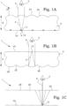
- Fig. 1A schematically illustrates one example of a synthetic-image device 1.
- the synthetic-image device 1 comprises a focusing element array 20 of focusing elements 22.
- the focusing element is a lens 24.
- the lens 24 is typically a spherical lens. In applications, where a difference between image properties in different surface directions, lenticular lenses may be used.
- the synthetic-image device 1 further comprises an image layer 10 comprising image objects 12.
- the image objects 12 are objects that are optically distinguishable from parts 14 of the image layer 10 that are not covered by image objects 12.
- the image objects 12 may e.g. be constituted by printed product micro features 11 and/or embossed microstructures.
- the image layer 10 is arranged in a vicinity of a focal distance d of the focusing elements 22 of the focusing element array 20. This means that a parallel beam 6 of light impinging on a focusing element 22 will be refracted 5 and focused at one point or small area 4 at the image layer 10. Likewise, light emanating from one point at the image layer 10 will give rise to a parallel beam 6 of light when passing the focusing elements 22.
- a point at an image object 12 will therefore appear to fill the entire surface of the focusing element 22 when viewed from a distance in the direction of the produced parallel beam 6 by a viewer, schematically illustrated by the eye 2.
- the material 9 between the image layer 10 and the focusing element array 20 is at least partly transparent and is typically constituted by a thin polymer foil.
- the distance d does not have to be exactly equal to the focusing distance of the focusing elements 22.
- there is always a certain degree of aberrations which anyway broadens the area from which the optical information in a parallel beam 6 is collected. This appears more at shallower angles and in order to have a more even general resolution level, a distance in a vicinity, but not exactly equal to the focal distance may be beneficially selected.
- the focusing element surface has a certain two-dimensional extension, also this surface could be used to produce fine objects of the total synthetic image.
- fine objects of a small area on the image layer 10 may be beneficial to enlarge to cover the surface of the focusing element, which means that also in such a case, the actual selected distance d is selected to be in a vicinity, but not exactly equal to the focal distance.
- the actual selected distance d is selected to be in a vicinity, but not exactly equal to the focal distance.
- the part images produced at each individual focusing element 22 surface will collectively be perceived by a viewer 2 as a synthetic image.
- Different images may be displayed for the viewer when the synthetic-image device 1 is viewed in different directions, which opens up for creating different kinds of optical effects, as will be described further below.
- Fig. 1B schematically illustrates another example of a synthetic-image device 1.
- the focusing elements 22 are constituted by concave mirrors 26.
- the image layer 10 is here situated on the front surface with reference to the viewer 2 and the focusing element array 20 is situated behind the image layer 10.
- the rays 5 of light travelling from the image objects to the viewer 2 pass the material 9 of the synthetic-image device twice.
- Fig. 1C schematically illustrates yet another example of a synthetic-image device 1.
- the focusing elements are pinholes 28, restricting the light coming from the image layer 10 and passing through to the viewer 2.
- the synthetic image is built by the narrow light beams passing the pinholes 28, and are typically only providing "light” or "dark”. Since the pinholes 28 doesn't have any enlarging effect, most of the viewed surface does not contribute to the synthetic image.
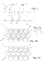
- Fig. 2 illustrates schematically the selection of different part areas 4 of the image layer 10.
- the image layer 10 comprises image objects 12.
- the area 4 that is enlarged by the focusing element 22 is situated at the centre line, illustrated in the figure by a dotted line, of the focusing element 22. If an image object 12 is present at that position, an enlarged version is presented at the surface of the synthetic-image device 1. However, as in the case of Fig. 2 , no image object is present, and there will be no enlarged image at the surface of the synthetic-image device 1.
- the area 4 on which the focusing element 22 focuses is shifted at the side.
- the area 4 overlaps with at least a part of an image object 12 and an enlarged version can be seen at the surface of the synthetic-image device 1.
- the images presented at the surface of the synthetic-image device 1 may change for different viewing angles, which can be used for achieving different kinds of optical effects of the synthetic images.
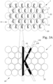
- FIG. 3A schematically illustrates in the upper part an example of a part of an image layer 10.
- the image layer 10 comprises a repetitive pattern 15 of image objects 12.
- the image objects 12 are selected to be the letter "K".
- Focusing elements 22 associated with the illustrated part of the image layer 10 are illustrated by dotted circles, to indicate the relative lateral position.
- Both the repetitive pattern 15 of image objects 12 and the focusing element array 20 have a hexagonal symmetry. However, the distance between two neighbouring image objects 12 is slightly shorter than the distance between two neighbouring focusing elements 22 in the same direction.
- An area 4 is also marked, which corresponds to the focusing area of each focusing element 22.
- the area 4 corresponds to a view direction straight from the front.
- the parts of the image objects 12 that are present within each of the areas 4 will thereby be presented in an enlarged version over the surface of the corresponding focusing element 22, here denoted as a projected image 25.
- the corresponding focusing element array 20 is illustrated including the projected images 25 of the image objects 12 of the areas 4.
- the dotted lines from one of the areas 4 in the upper part to one of the focusing elements 22 in the lower part illustrates the association.
- the different projected images at the focusing elements 22 together forms a synthetic image 100.
- the synthetic image 100 is a part of a large "K". If these structures are small enough, the human eye will typically fill in the empty areas between the focusing elements 22 and the viewer will perceive a full "K". The reason for the K to be produced is the existence of the slight period mismatch between the repetitive pattern 15 of image objects 12 and the focusing element array 20. In this example, using the mismatch between a repetitive image pattern 15 and an array of focusing elements 22, the synthetic image is called a moiré image 105.
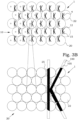
- Fig. 3B schematically illustrates the same synthetic-image device 1 as in Fig. 3A , but when viewed in another direction. This corresponds to a slight tilting of the synthetic-image device 1 to the left.
- the areas 4 which corresponds to the focusing areas of the focusing elements 22 in this direction are thereby moved somewhat to the left. This results in that another part of the image objects 12 are projected to the focusing elements 22, as seen in the lower part of the Fig. 3B .
- the result of the tilting is that the synthetic image 100, i.e. the large "K" moves to the right.
- magnification is positive, for P o > P l , the magnification becomes negative, i.e. the synthetic image 100 becomes inverted compared to the image objects 12.
- d the thickness of the synthetic-image device
- R l the radius of the curvature of the spherical microlenses.
- the moiré images have, however, certain limitations. First of all, they can only result in repetitive images. Furthermore, the size of the image objects 12 is limited to the size of the focusing elements. In Fig. 4A , an image object 13 is schematically illustrated. If this image object is repeated with almost the same period as for the focusing elements 22 of Fig. 4B , the repeated patterns of image objects 13 will overlap. The moiré image from such a structure will be almost impossible for the human brain to resolve, since parts of the image objects associated with a neighbouring focusing element 22 will interfere.
- FIG. 4C A solution is presented in Fig. 4C .
- a cell 16 of the image layer 10 is exclusively associated with each focusing element 22.
- each cell 16 only parts of an image object 17 belonging to one copy of the image object is preserved and the other interfering image objects are removed.
- the different image objects 17 will now not be identically repeated over the image layer 10 but instead the image objects 17 are successively changing in shape.
- a synthetic image will also be produced.
- a synthetic image based on non-identical fractioned image objects 17 within cells 16 associated with the focusing elements 22 is in this disclosure referred to as an integral synthetic image.
- FIG. 5 illustrates schematically such a design.
- each cell 16 occupies an area that is smaller than the area of an associated focusing element.
- the result will be that the integral synthetic image will disappear when the area of focus of the associated focusing element reaches the edge of the cell.
- a further change in viewing angle has to be provided before a "new" integral synthetic image appears. The relation with the disappearing image will then not be equally apparent.
- the ideas of having cells with different image objects can be driven further.
- the moiré synthetic images can be given an apparent depth, but is in principle restricted to one depth only. A true three-dimensional appearance is difficult to achieve.
- the freedom of changing the image objects from one cell to another can also be used e.g. to provide a more realistic three-dimensionality of the produced images.
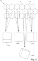
- Fig. 6 cells 16 of an image layer 10 are illustrated.
- Four different areas 4 for each cell 16 corresponding to focusing areas of associated focusing elements when viewed in four different directions are illustrated.
- Image objects of the centre area 4 in each cell corresponds to a viewing angle as achieved if the synthetic-image device is viewed in a perpendicular manner.
- Such image objects may then be designed such that they give rise to an integral synthetic image 110B as illustrated in the lower centre part of Fig. 6 showing a top surface of a box.
- Image objects of the uppermost area 4 in each cell corresponds to a viewing angle as achieved if the synthetic-image device is tilted away from the viewer.
- Such image objects may then be designed such that they give rise to an integral synthetic image 110A as illustrated in the lower left part of Fig.
- Image objects of the leftmost area 4 in each cell corresponds to a viewing angle as achieved if the synthetic-image device is tilted to the left with reference to the viewer.
- Such image objects may then be designed such that they give rise to an integral synthetic image 110C as illustrated in the lower right part of Fig. 6 , showing the top surface and a side surface of a box.
- Image objects of the area 4 in the lower right part in each cell corresponds to a viewing angle as achieved if the synthetic-image device is tilted towards and to the right with reference to the viewer.
- Such image objects may then be designed such that they give rise to an integral synthetic image 110D as illustrated at the very bottom of Fig. 6 , showing the top surface, a side surface and a back surface of a box.
- the integral synthetic image can be caused to have almost any appearances.
- the so achieved image properties can be simulations of "real" optical properties, e.g. a true three-dimensional image, but the image properties may also show optical effects which are not present in "real" systems.
- FIG. 7 An example of a part of an image layer 10 of an integral synthetic-image device giving rise to an image of the figure "5 " is illustrated in Fig. 7 .
- One effect that is possible to achieve by both moiré synthetic images and integral synthetic images is that two synthetic images can be imaged at the same time. These synthetic images have different apparent depth or height. When tiling such an optical device, the two synthetic images moves relative each according to the ordinary parallax effect. In certain viewing angles, the synthetic images may come in line of sight of each other, i.e. one object covers at least a part of the other object.
- Fig. 8 schematically illustrates one cell of such a situation.
- the cell 16 at the left is illustrated with a first set 31 of image objects, in this particular illustration a complex figure with narrow tongues, intended to contribute to a first synthetic image at a certain apparent depth.
- the cell 16 in the middle is likewise illustrated with a second set 32 of image objects, in this particular illustration a square, intended to contribute to a second synthetic image at an apparent depth, larger than for the first synthetic image.
- a combination of these two cells gives a cell 16 as illustrated in the right part of Fig. 8 .
- the first set 31 of image objects covers parts of the second set 32 of image objects, and such parts are therefore omitted.
- One may interpret it as if one cuts off such parts of the second set 32 of image objects that overlaps with the first set 31 of image objects.
- a composite image object 33 is thereby created by adding selected parts of the second set 32 of image objects to the first set 31 of image objects.
- the first synthetic image comes in front of the second synthetic image. If both the synthetic images are based on a same or at least similar colour, it becomes difficult for the viewer to distinguish which part belongs to which object.
- the correlation made by the human brain between the part images provided by each focusing element is not totally obvious. The result may be that the viewer experiences a blurred image or that the depth feeling, at least partly, disappears. In particular in cases where narrow structures, as the tongues of the first set 31 of image objects, are involved, the composite image often becomes deteriorated.
- a synthetic-image device comprises an image layer and a focusing element array.
- the image layer is, as was described earlier, arranged in a vicinity of a focal distance of focusing elements of the focusing element array.
- the image layer comprises composite image objects. These composite image objects of the image layer array are a conditional merging of at least a first set of image objects, an envelope area associated with the first set of image objects and a second set of image objects.
- the first set of image objects is arranged for giving rise to at least a first synthetic image at a non-zero height or depth when being placed in a vicinity of a focal distance of focusing elements and viewed through the focusing element array.
- the second set of image objects is arranged for giving rise to at least a second synthetic image at a non-zero height or depth when being placed in a vicinity of a focal distance of focusing elements and viewed through the focusing element array.
- the envelope area of the first set of image objects is an area covering the first set of image objects and further comprises a margin area not covering the first set of image objects.
- the idea is to introduce a margin when deciding which parts of the first set of image objects that are going to be cut away. Instead of only cutting such parts that are directly overlapping, also some parts outside the first set of image objects may be removed. The envelope area thereby operates as a mask to decide which parts of the first set of image objects that are to be removed.
- a cell 16 is illustrated with a first set 31 of image objects, in this particular illustration the complex figure with narrow tongues used in Fig. 8 , intended to contribute to a first synthetic image.
- an envelope area 35 is illustrated. This envelope area 35 covers the first set 31 of image objects.
- the envelope area 35 further comprises a margin area 34.
- the margin area 34 does not cover the first set 31 of image objects. Instead, the margin area 34 is used to create a buffer zone outside the first set 31 of image objects where no disturbing other objects are to be allowed.
- the margin area 34 comprises a narrow rim 34A around the entire first set 31 of image objects.
- the envelope area 35 has a main shape that is congruent with an envelope of the image objects of said first set 31 of image objects. This prohibits a confusion between the outer borders a first synthetic image and a second synthetic image at least partially overlapping each other. Furthermore, the margin area also covers the entire area 34B between the upper broad tongue and the uppermost narrow tongue of the first set 31 of image objects. This prohibits an underlying second synthetic image to disturb the appearance of the interior of an overlying first synthetic image.
- composite image objects 36 are created. Selected parts of the second set 32 of image objects are added to the first set 31 of image objects, however, now masked by the envelope area 35 rather than by the first set 31 of image objects itself.
- the synthetic-image device gives rise to a combined synthetic image composed by the first synthetic image based on the first set of image objects and the second synthetic image based on the second set of image objects.
- the use of the envelope area 35 as a masking facilitates the interpretation made by the human brain about which parts that belongs to which structure. A more clear combined synthetic image is thus produced.
- the width of the narrow rim 34A is selected to be large enough to assist the eye to separate the different synthetic images. At the same time, it is preferred that the narrow rim 34A is narrow enough not to constitute a synthetic image at its own.
- the actual sizes depends on different parameters, such as magnification, focusing element aberration, focusing element strength etc. and could be adapted for different applications.
- An average width of objects of the margin area is within the range of 0.1% to 10% of a diameter of the focusing elements.
- Each of the first synthetic image and the second synthetic image can be a moiré image or an integral synthetic image.
- first synthetic image and the second synthetic image are integral synthetic images.
- first synthetic image is an integral synthetic image.
- both the first synthetic image and the second synthetic image are integral synthetic images.
- the appearance of a cell 16 indicates that at least the first synthetic image is an integral image.
- first synthetic image and the second synthetic image are moiré images.
- the second synthetic image is a moiré image.
- both the first synthetic image and the second synthetic image are moiré images.
- the image objects of the first set 31 of image objects are limited to a certain area of cell 16.
- the second set of image objects can be intended to give rise to a moiré image, and its image objects are therefore not limited by the area of the cell 16 of the first set 31 of image objects.
- the image objects of the second set of image objects may be controlled to appear in other areas.
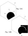
- Figs. 10A-B a first set 31 of image objects is illustrated within a cell 16.
- An envelope area 35 is defined, comprising the area of the first set 31 of image objects as well as a margin area 34. It can, however, be noticed that the margin area 34 does not include any parts essentially along the border of the cell 16, but just at the corners of the first set 31 of image objects.
- the second set of image objects is here a set intended for creating a moiré image and is thus not limited by the cell 16.
- a margin is created between the two sets within the cell 16, but not at the cell border.
- the first set of image objects 31 are provided within a set of first cells 16, wherein each said first cell 16 is associated with a respective focusing element of the focusing element array.
- the margin area 34 encloses edges of first images objects not coinciding with borders of the first cells.
- a first set of image objects and its associated envelope area may thereby mask or cut more than one other set of image objects.
- the second set of image objects may be considered as a combined set of image objects, composed by two or more sets of image objects.
- Such a composed set of image objects may itself comprise a cutting or masking by use of envelope areas.
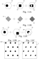
- Fig. 11A illustrates a cell 16 at the leftmost part of the figure that comprises a first set of image objects 31 in the form of a circular disc.
- a second set of image objects 32 has the shape of a square.
- composite image objects 37 are illustrated which are the results of a conditional merging of the first set of image objects 31 and the second set of image objects 32.
- the conditional merging is that the composite image objects are present only in points where either the first set of image objects exists or the second set of image objects exists but not both.
- the conditional merging is an exclusive "OR" condition.
- FIG. 11B Another example of such an exclusive "OR" conditional merging is illustrated in Fig. 11B .
- a first set of image objects 31, belonging to a moiré image is combined with a second set of image objects 32, also belonging to a moiré image.
- exclusive "OR" conditional merging between one set of image objects associated with a moiré image and one set of image objects associated with an integral synthetic image can be used.
- FIG. 12A illustrates one embodiment, where in the leftmost part, a cell 16 comprises a first set of image objects 31, in the form of a circular disc. In the cell 16 in the middle of the figure, a second set of image objects 32 has the shape of a square. In the right-hand part of the figure, composite image objects 38 are illustrated which are formed in dependence on the first set of image objects 31 and the second set of image objects 32. A dotted line indicates the position of the second set of image objects 32, as a guide for the present illustration.
- the composite image objects 38 are a conditional appearance of the first set of image objects 31 dependent on the second set of image objects 32.
- the first set of image objects 31 is preserved only in positions where the second set of image objects 32 do not overlap.
- the composite image objects 38 can also be seen as a conditional merging of at least a first set of image objects 31 and a second set of image objects 31, where the conditional merging is that the composite image objects 38 are present only in points where the first set of image objects 31 exists but the second set of image objects 32 does not exist.
- FIG. 12B a schematic illustration of how the synthetic-image device 1 may look like from one viewing angle.
- the first set of image objects 31 and the second set of image objects 32 do not overlap in this viewing direction and a composite synthetic image 120 in the form of full circular discs is seen.
- Fig. 12C illustrates the same synthetic-image device 1, but now tilted in another angle.
- the first set of image objects 31 and the second set of image objects 32 do now partially overlap in this viewing direction and a composite synthetic image 120 in the form of three-quarter circular discs is seen.
- the second set of image objects 32 does never give rise to any directly perceivable synthetic image 120. However, since the second set of image objects 32 is used as a condition for the appearance of the first synthetic image, parts of the shape of the intended synthetic image associated with the second set of image objects 32 may be seen as the borders of the appearing eclipses.
- Fig. 13A is a schematic illustration of another synthetic-image device 1.
- a first set of image objects 31 is associated with a moiré image of squares.
- a second set of image objects 32 is associated with an integral synthetic image of a car.
- a composite synthetic image 120 as illustrated in Fig. 13A is achieved.
- the repetitive pattern of the squares is shown except for the positions where the integral synthetic image of the car would have been seen.
- the viewer may anyway figure out how the image would have looked like by tilting the synthetic-image device 1 in different directions.
- Fig. 13B is a schematic illustration of another synthetic-image device 1.
- the first and second sets of image objects from Fig. 13A have been exchanged.
- the appearance of the integral synthetic image of the car is conditioned depending on the non-existence of the moiré image of squares.
- one set of image objects gives a field-of-view control for another set of image objects.
- Fig. 14A illustrates one embodiment, where in the leftmost part, a cell 16 comprises a first set of image objects 31, in the form of a circular disc. In the cell 16 in the middle of the figure, a second set of image objects 32 has the shape of a triangle. In the right-hand part of the figure, composite image objects 39 are illustrated which are formed in dependence on the first set of image objects 31 and the second set of image objects 32. A dotted line indicates the positions of the first and second sets of image objects 31, 32, as a guide for the present illustration. The composite image objects 39 are a conditional appearance of the first set of image objects 31 dependent on the second set of image objects 32.
- the first set of image objects 31 is preserved only in positions where the second set of image objects 32 overlaps.
- the composite image objects 39 can also be seen as a conditional merging of at least a first set of image objects 31 and a second set of image objects 31, where the conditional merging is that the composite image objects 39 are present only in points where both the first set of image objects 31 and the second set of image objects 32 exist.
- FIG. 14B a schematic illustration of how the synthetic-image device 1 may look like from one viewing angle.
- the first set of image objects 31 and the second set of image objects 32 overlap in this viewing direction at the upper part of the triangle and a composite synthetic image 130 in the form of a triangle top is seen.
- Fig. 12C illustrates the same synthetic-image device 1, but now tilted in another angle.
- the first set of image objects 31 and the second set of image objects 32 do now partially overlap with other parts in this viewing direction and a composite synthetic image 130 in the form of a triangle cut by circular border is seen.
- the first set of image objects 31 does never give rise to any directly perceivable synthetic image 120 if not overlapping with the second set of image objects 32.
- the second set of image objects 32 does never give rise to any directly perceivable synthetic image 120 if not overlapping with the first set of image objects 31.
- One of the sets of image objects is thus needed to "develop" the other set of image objects.
- Fig. 15 is a schematic illustration of another synthetic-image device 1 based on the same first set of image objects and second set of image objects as in Figs. 13A-B . However, here conditional merging as in Figs. 14A-C above is used for producing a composite synthetic image 130.
- a synthetic-image device comprises an image layer and a focusing element array.
- the image layer is arranged in a vicinity of a focal distance of focusing elements of the focusing element array.
- the image layer comprises composite image objects.
- the composite image objects of the image layer array are a conditional appearance of a first set of image objects dependent on a second set of image objects.
- the first set of image objects gives rise to a first synthetic image at a non-zero height or depth when being placed in a vicinity of a focal distance of focusing elements and viewed through the focusing element array.
- the second set of image objects gives rise to a second synthetic image at a non-zero height or depth when being placed in a vicinity of a focal distance of focusing elements and viewed through the focusing element array.
- the composite image objects of the image layer array are a conditional merging of at least the first set of image objects and the second set of image objects.
- the conditional merging is that the composite image objects are present only in points where the first set of image objects exists but the second set of image objects does not exist and/or the composite image objects are present only in points where both the first set of image objects and the second set of image objects exist.
- conditional merging is that the composite image objects are present only in points where the first set of image objects exists but the second set of image objects does not exist.
- conditional merging is that the composite image objects are present only in points where both the first set of image objects and the second set of image objects exist.
- FIG. 16 an example of a synthetic-image device 1 is schematically illustrated, where a conditional merging is based on that the composite image objects are present only in points where both the first set of image objects and the second set of image objects exist.
- the second set of image objects gives rise to three large squares 131, which are essentially colour-free or transparent.
- the first set of image objects gives rise to an array 132 of "1".
- the conditional merging results in that the array 132 of "1" only is visible when coexisting with the squares 131.
- the optical effect of the synthetic-image device 1 is that the viewer perceives that the array 132 of "1" is seen through a "window" created by the squares 131.
- one set of image objects gives a field-of-view control for another set of image objects.
- optical effects can be achieved, both effects that resembles optical effects of the three-dimensional physical world and effects that behaves in "strange” manners.
- At least one of the first synthetic image and the second synthetic image is a three-dimensional image. This gives the possibility to combine typical three-dimensional view effects with parallax-caused effects.
- magnification depends on the relation between the periodicity of the focusing elements and the periodicity of the image objects.
- a small difference gives rise to a high magnification.
- the difference comes extremely close to zero, i.e. when the ratio of periodicities becomes very close to 1, the magnification approaches infinity.
- the synthetic image no longer is perceivable by a viewer, since the same optical information is presented by each of the focusing elements.
- such types of synthetic images, of moiré image type or integral synthetic image type may anyway be useful.
- the viewing angles becomes slightly different for the different focusing elements, and the "infinite" magnification becomes revoked. This can easily be utilized e.g. for security markings.
- Such synthetic images may also advantageously be used in combination with the above described composite image object aspects.
- the first set of image objects gives rise to the first synthetic image when viewed through said focusing element array from a distance less than 15 cm and/or the second set of image objects giving rise to the second synthetic image when viewed through the focusing element array from the distance less than 15 cm.
- Another design alternative is to create a synthetic image with an infinite magnification in one direction, but a finite magnification in a perpendicular direction. Also such a synthetic image will be un-perceivable when presented for a viewer in a flat form. However, by bending the synthetic-image device around an axis transversal to the axis of the infinite magnification, the relations between the periods of the focusing elements and the periods of the image objects change, giving rise to a finite magnification in both directions. The synthetic image then becomes perceivable.
- the first set of image objects gives rise to the first synthetic image when viewed through a bent focusing element array and/or the second set of image objects giving rise to the second synthetic image when viewed through a bent focusing element array.
- This effect can be achieved by moiré images, where the pitch of the repeated image objects is modified.
- integral synthetic images may also be designed to give a similar effect.
- the combination of sets of image objects can be developed further by using additional sets of image objects on which composite image objects are dependent.
- the additional sets of image objects may overlap with the first and/or second sets of image objects, and all sets of image objects may then be involved in the conditional merging in at least some areas of the image layer.
- the additional sets of image objects may in other alternatives only be provided as non-overlapping with the first and/or second sets of image objects and the conditional merging may then be different for different part areas of the image layer.
- composite image objects of the image layer array is further dependent on at least one additional set of image objects.
- This additional set of image object gives rise to an additional synthetic image when being placed in a vicinity of a focal distance of focusing elements and viewed through the focusing element array.
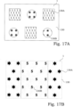
- Fig. 17A illustrates a synthetic-image device 1 based on several sets of image objects giving rise to a total composite synthetic image.
- a first composite synthetic part image 130A resembles the composite synthetic image of Fig. 16 .
- the total composite synthetic image 130 also presents a second composite synthetic part image 130B, here illustrated as a star pattern as seen through a circular "window".
- two sets of image objects cooperate to form the first composite synthetic part image 130A and two other sets of image objects cooperate to form the second composite synthetic part image 130B.
- Fig. 17B illustrates another synthetic-image device 1 based on several sets of image objects giving rise to a total composite synthetic image.
- the two part images 130A and 130B here appear at the same apparent depth and are furthermore aligned to each other.
- the "windows" defining the different areas will move and the result is a sweeping flip of the stars into "5"'s and vice versa.
- the patterns used for defining the sweeping areas have a period that is larger than the size of the windows.
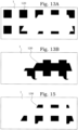
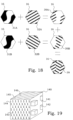
- Fig. 18 an illustration on a cell level is illustrated.
- a first set of image objects 31A is combined with a second set of image objects 32A to form part composite image objects 39A.
- a third set of image objects 31B is combined with a fourth set of image objects 32B to form part composite image objects 39B.
- the part composite image objects 39A, 39B are combined into a final composite image objects 39.
- Fig. 19 illustrates one more elaborate example of a composite synthetic image 140 in the form of a three-dimensional cube 149.
- a "window” is presented, through which an array 142 of smaller three-dimensional cubes is seen.
- another "window” is presented, through which an array 144 of "1" is seen.
- a third side 145 of the cube 149 yet another "window” is presented, through which an array 146 of lines is seen.
- the arrays 142, 144, 146 being seen through the different sides 141, 143, 145 will also follow in new view of the large three-dimensional cube 149 and be adapted to the new position and shape of the respective side 141, 143, 145.
- the actual combination of the different sets of image objects is preferable made before the image layer is created.
- numerical representations of the sets of image objects are instead created.
- an envelope area is used for creating the composite image objects, also this is expressed by a numerical representation.
- the combination into a composite image object is then performed on these numerical representations.
- the image layer is created according to that numerical representation.
- the transfer of the numerical representation into a physical image layer is performed according to well-known manufacturing principles, using e.g. different kinds of printing or embossing.
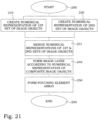
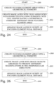
- Fig. 20 illustrates a flow diagram of steps of an embodiment of a method for producing a synthetic-image device.
- the method starts in step 200.
- step 210 a numerical representation of a first set of image objects is created.
- the first set of image objects is arranged for giving rise to at least a first synthetic image at a non-zero height or depth when being placed in a vicinity of a focal distance of focusing elements and viewed through the focusing element array.
- a numerical representation of an envelope area associated with the first set of image objects is created.
- the envelope area of the first set of image objects is an area covering the first set of image objects and further comprising a margin area not covering the first set of image objects.
- step 220 a numerical representation of a second set of image objects is created.
- the second set of image objects is arranged for giving rise to at least a second synthetic image at a non-zero height or depth when being placed in a vicinity of a focal distance of focusing elements and viewed through the focusing element array.
- the numerical representation of the first set of image objects, the numerical representation of the envelope area associated with the first set of image objects and the numerical representation of the second set of image object are merged according to a predetermined condition into a numerical representation of composite image objects.
- the conditional merging is that the composite image objects are present only in points where the first set of image objects exists or in points where the second set of image objects exists but the envelope area associated with the first set of image objects does not exist.
- an image layer is formed according to the numerical representation of composite image objects.
- a focusing element array is formed. The image layer is arranged in a vicinity of a focal distance of focusing elements of the focusing element array. The process ends in step 299.
- the steps 240 and 250 can be performed in either order or at least partially simultaneously.
- Fig. 21 illustrates a flow diagram of steps of an example of a method for producing a synthetic-image device.
- the method starts in step 200.
- step 210 a numerical representation of a first set of image objects is created.
- the first set of image objects is arranged for giving rise to at least a first synthetic image at a non-zero height or depth when being placed in a vicinity of a focal distance of focusing elements and viewed through the focusing element array.
- a numerical representation of a second set of image objects is created.
- the second set of image objects is arranged for giving rise to at least a second synthetic image at a non-zero height or depth when being placed in a vicinity of a focal distance of focusing elements and viewed through the focusing element array.
- step 231 the numerical representation of the first set of image objects and the numerical representation of the second set of image object are merged into a numerical representation of composite image objects.
- the composite image objects of the image layer array are a conditional appearance of the first set of image objects dependent on the second set of image objects.
- step 240 an image layer is formed according to the numerical representation of composite image objects.
- step 250 a focusing element array is formed. The image layer is arranged in a vicinity of a focal distance of focusing elements of the focusing element array. The process ends in step 299.
- the steps 240 and 250 can be performed in either order or at least partially simultaneously.
- the numerical representations of the image objects are vector representations of areas.
- the objects are described by polygons which can be rendered smoothly at any desired display size.
- the polygons smoothness is generally adjusted to match the resolution of step 240, in order to avoid too large amount of data.
- the numerical representations of the image objects are pixel-based.
- the total area is then divided into a number of pixels.
- Each pixel is then defined as either belonging to the image object or belonging to a surrounding.
- the different logic operations are in such an approach performed essentially pixel by pixel.
- the merging 231 is that the composite image objects are present only in points where the first set of image objects exists but the second set of image objects does not exist and/or the composite image objects are present only in points where both the first set of image objects and the second set of image objects exist.
- Fig. 22A illustrates such a situation, where a hexagonal cell 16 is associated with each focusing element 22.
- the maximum area of the cell 16 is equal to the total area divided by the number of focusing elements 22. If the focusing elements 22 have a circular border as in the illustration, the cell 16 may be slightly larger than the actual base area of the focusing element 22.
- the cells may also be smaller than the maximum allowed size, e.g. for making image flips less pronounced, as discussed further above.
- the density of the cells 16 equals the density of focusing element 22. In other words, each cell 16 can be associated to a unique focusing element 22.
- FIG. 22B illustrates one example, where rectangular cells 16 are used together with the hexagonally distributed focusing elements 22. Still, each cell 16 is associated with a focusing element 22. The distribution of the cells 16 is still made in a regular hexagonal pattern, even if the cells 16 themselves are shaped as rectangles. In this example, the area of the cells 16 is equal to the maximum area and the cells 16 thus occupies the entire surface of the image layer.
- the cells 16 may be preferred in different applications.
- the cells 16 comprise image objects 12 creating a phrase "PHRASE" in each cell 16.
- the length of the phrase is larger than the focusing element diameter and in order not to induce any flip of the integral synthetic image when a viewer tries to read the entire phrase, the dimension of the cell 16 in the direction of the phrase is allowed to be larger than the diameter of the focusing element 22.
- the cell 16 is made narrower in a perpendicular direction. This means that the synthetic-image device 1 can be tilted to a larger angle in the horizontal direction, as illustrated, than in the vertical direction, without causing any flip of the integral synthetic image.
- the integral synthetic image as in this case, is a text, flips in the horizontal direction, i.e. the reading direction, is generally more disturbing than a flip in the vertical direction.
- the selection of the geometry and size of the cell 16 solves such problems.
- Another use of extending the cell range may be in connection with lenses with high F numbers.
- the angle necessary for reaching the border of a hexagonal cell is then relatively low, and flips between integral synthetic images therefore occurs more frequently when tilting such devices.
- these effects can be mitigated in one direction by instead extend the cell in that direction.
- the disadvantage is, however, that the angle range before a flip occurs in a transverse direction becomes smaller.
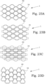
- FIG. 23A a rhombic cell shape is used, also giving a slightly larger tilt angle horizontally before an image flip occurs.
- the cell shape may also comprise non-linear borders, such as e.g. in Fig. 23B .
- a somewhat larger horizontal tilt is allowed before a flip, if the horizontal tilt is moderate.
- the integral synthetic image will first disappear at one tilt angle and only by a further tilting, the "flipped" integral synthetic image will appear. This behaviour is sometime experienced as less disturbing than a direct flip.
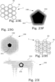
- Fig. 23D illustrates a complex cell shape, which may be useful if dense hexagonal integral synthetic images are to be produced. This will be further discussed below.
- the focussing elements typically present different kinds of optical aberrations. This means that the focusing that is achieved is not totally perfect. Also some light emanating from areas slightly outside the intended area, for a certain viewing direction, is thereby refracted by the focussing elements in that viewing direction. The result is a diffuse shadowing in the colour of the object to be seen.
- the shape of this shadowing depends on both the shape of the object intended to be imaged and the shape of the cell, and is in principle some sort of convolution of the shapes.
- the appearance of such a shadow may be disturbing. This may be even more accentuated if the shadow presents distinct geometrical features, e.g. caused by a cell having such distinct geometrical features. In such cases, it is might be wise to select a cell that has a relatively neutral shape. Circular cells 16, such as illustrated in Fig. 23E , or regular polygons with many corners, may be favourable compared to e.g. rectangular cells.
- Fig. 23F illustrates very schematically a synthetic image 100 presenting a pentagon object 101, where a low magnification is used in the synthetic-image device.
- a diffuse shadow 102 may appear, having geometrical resemblance with the object 101.
- the cell shape, which here is hexagonal, is playing a minor role in the shadows shape.
- Fig. 23G a similar illustration shows a synthetic image 100 presenting a pentagon object 101, but where a high magnification is used in the synthetic-image device.
- the shadow 102 is more distinct and the hexagonal shape of the cell here gives a more distinct limitation of the shadow.
- a synthetic-image device 1 is illustrated, having cells 16 in the shape of an animal.
- the animal shape can be vaguely distinguished in the shadowing 102 in the synthetic image 100.
- a synthetic-image device comprises a focusing element array and an image layer.
- the focusing element array is a two-dimensional periodic array having a geometrical symmetry.
- the image layer is arranged in a vicinity of a focal distance of focusing elements of the focusing element array.
- the image layer has sets of image objects arranged in cells of a cell array, wherein each cell is associated with a respective one of the focusing elements.
- the set of image objects is arranged for giving rise to at least a first synthetic image when being placed in a vicinity of a focal distance of the focusing elements and viewed through the focusing element array.
- Each of the cells has a shape with a geometrical symmetry that is different from the geometrical symmetry of the two-dimensional periodic array.
- the area of the cells is less than the area of the focusing element array divided by the number of focusing elements of the focusing element array.
- the focusing element array has a hexagonal geometrical symmetry.
- Fig. 24 illustrates a flow diagram of steps of an embodiment of a method for producing a synthetic-image device.
- the method starts in step 200.
- a focusing element array is created as a two-dimensional periodic array having a geometrical symmetry.
- an image layer is created with sets of image objects arranged in cells of a cell array, wherein each cell is associated with a respective one of the focusing elements.
- Each of the cells has a shape with a geometrical symmetry that is different from the geometrical symmetry of the two-dimensional periodic array.
- the set of image objects is arranged for giving rise to at least a first synthetic image when being placed in a vicinity of a focal distance of the focusing elements and viewed through the focusing element array.
- the image layer is arranging in a vicinity of the focal distance of focusing elements of the focusing element array. The procedure ends in step 299.
- the steps 260 and 262 can be performed in either order or at least partially simultaneously and/or as a common process. Furthermore, the step 264 can be performed at least partially simultaneously and/or as a common process to steps 260 and/or 262.
- pattern size, magnification, apparent depth/height etc. can be selected according to what is most appropriate for each application. In certain applications based on repetitive patterns, it might even be of interest to provide more than one item associated with each focusing element. This may e.g. be useful if a small apparent image size and a large apparent depth are requested at the same time.
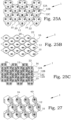
- FIGs. 25A-C some examples of how image array symmetry and the number of items in each cell may be altered to increase to possibilities for selecting appropriate image designs.
- a synthetic-image device 1 is schematically illustrated, where three identical part image objects 12A-C, together constituting a set of image objects 12, are provided within the area of each focusing element 22.
- the correlation between the projected images of the different focusing elements here occurs between one of the part image objects 12A-C and a corresponding part image object in the neighbouring cells.
- the symmetry of both the focusing element array 10 and the produced synthetic image is of a hexagonal symmetry. However, the main axes are rotated 90° with respect to each other.
- part image objects 12A-C are perfectly aligned to each other over the entire device, some of the depth feeling may be difficult to achieve. This may be dependent on that the eye becomes confused by competitive image object parts and thereby cannot obtain an apparent depth correctly. However, such artefacts may easily be corrected for by on purpose misalign the part image objects 12A-C a very small distance, typically less than 1% of the cell diameter. The eye will now be assisted in the correct correlation at the same time as the parts of the synthetic image are displaced such a small distance that the misalignment is not perceived.
- a synthetic-image device 1 is schematically illustrated, where basically one object per cell 16 constitutes the set of image objects 12.
- the cells 16 have a rhombic shape.
- Fig. 25C both these aspects are combined.
- four part image objects 12A-D are positioned in each cell 16.
- the image objects are further adapted to give different magnifications in different directions. If the magnification in horizontal direction becomes 2 3 times the magnification in vertical direction, the so produced integral synthetic image becomes a square regular pattern with the main axis in horizontal and vertical directions, respectively.
- the icons can be stretched or compressed in one direction to get the right icon shape when applying different magnification horizontally and vertically.
- Table 1 Combinations of multiple objects per cell with different horizontal and vertical magnifications to achieve different packings. Magnification ratio 1 1 3 2 3 3 # of objects per cell 1 Hexagonal packing 45° rotated square packing - - 2 Rectangular packing Square packing - - 3 90° rotated hexagonal packing - - 45° rotated square packing 4 Rectangular packing Rectangular packing Square packing Rectangular packing 6 Rectangular packing Rectangular packing Rectangular packing Rectangular packing Square packing
- Table 1 summarizes some different combinations of multiple objects per cell with different horizontal and vertical magnifications to achieve different packings.
- the magnification ratio is given as the magnification in a direction parallel to a closed-packed direction of the hexagonal focusing element array divided by the magnification in a direction perpendicular to the closed-packed direction of the hexagonal focusing element array.
- a synthetic-image device comprises a focusing element array and an image layer.
- the focusing element array is a two-dimensional periodic array having a geometrical symmetry.
- the image layer is arranged in a vicinity of a focal distance of focusing elements of the focusing element array.
- the image layer has sets of image objects arranged in cells of a cell array, wherein each cell is associated with a respective one of the focusing elements.
- the set of image objects is arranged for giving rise to at least a first synthetic image when being placed in a vicinity of a focal distance of the focusing elements and viewed through the focusing element array.
- the image objects being arranged to present different magnifications in two perpendicular directions within the plane of the synthetic-image device.
- each of the cells has a shape with a geometrical symmetry that is different from the geometrical symmetry of the two-dimensional periodic array.
- the image objects of each cell comprises at least two displaced copies of a set of image objects.
- the focusing element array has a hexagonal geometrical symmetry.
- Fig. 26 illustrates a flow diagram of steps of an embodiment of a method for producing a synthetic-image device.
- the method starts in step 200.
- a focusing element array is created as a two-dimensional periodic array having a geometrical symmetry.
- an image layer is created with sets of image objects arranged in cells of a cell array, wherein each cell is associated with a respective one of the focusing elements.
- the image objects being arranged to present different magnifications in two perpendicular directions within the plane of the synthetic-image device.
- the set of image objects is arranged for giving rise to at least a first synthetic image when being placed in a vicinity of a focal distance of the focusing elements and viewed through the focusing element array.
- the image layer is arranging in a vicinity of the focal distance of focusing elements of the focusing element array. The procedure ends in step 299.
- the steps 260 and 263 can be performed in either order or at least partially simultaneously and/or as a common process. Furthermore, the step 264 can be performed at least partially simultaneously and/or as a common process to steps 260 and/or 263.
- Fig. 27 illustrates a synthetic-image device 1 combining other optical effects.
- a set of image objects 12 is provided, giving a normal synthetic image.
- the cells 16 have areas 40 that are coloured with a partially transparent colour.
- the areas 40 are provided with the same period as the focusing element array. The areas are thus not giving rise to any perceivable image, but will instead change the background colour, when the focusing areas of the focusing elements in certain directions of view will move into the coloured areas 40.
- a synthetic-image device comprises a focusing element array and an image layer.
- the image layer is arranged in a vicinity of a focal distance of focusing elements of the focusing element array.
- the image layer comprises composite image objects.
- the composite image objects of the image layer array are a conditional appearance of a first set of image objects dependent on a second set of image objects.
- the first set of image objects gives rise to a first synthetic image at a non-zero height or depth when being placed in a vicinity of a focal distance of focusing elements and viewed through the focusing element array.
- the second set of image objects is arranged at a same periodicity as the focusing elements of the focusing element array.
- the different configurations of cells and image objects as presented above can be applied as such in synthetic-image devices.
- the different configurations can also by advantage be combined with e.g. the application of logics between different "layers" of image objects.
- the different aspects can thereby be combined depending on the nature of the synthetic image that is intended to be presented.
- a focusing element array 20 of the synthetic-image device 1 comprises focusing elements 22, here spherical lenses 24, positioned with a periodicity of Pl and a radius of r.
- the set of image objects 12 is positioned at the image layer 10 with a periodicity of Po.
- the image objects 12 are in this case positioned straight below each focusing element 22.
- the synthetic-image device 1 has a thickness of t.
- the periodicity of Po and the periodicity of Pl are equal. This means that a synthetic image produced by this synthetic-image device 1 has an infinite magnification and a viewer will therefore only experience a diffuse device surface.
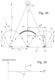
- a point light source 50 or at least a light source emitting essentially diverging rays, is then placed on a distance d from a synthetic-image device 1. Note that some dimensions in the figure are extremely exaggerated in order to better visualize the optical effects.
- the light impinging at a right angle on the synthetic-image device 1, as illustrated in the middle of the figure, is refracted into one focus spot positioned at the image object 12. That spot on the image object 12 therefore becomes intensively illuminated. Light emitted from this spot will be emitted in all directions. A main part of that re-emitted light will reach the lenses 24 at the lens straight above the emitting spot. Some of this light will be scattered and the lens surface 52 will be experienced as having the same colour as the image object 12.
- the impinging angle ⁇ is different. This means that the spot at which the light is focused will be displaced somewhat sideward. This is seen at the lenses at the sides of the figure.
- the focus spot here is positioned outside the image object 12 and no, or at least much less, light will be re-emitted. Consequently, the surface of the associated lens is not experienced as coloured.
- the distance between the light source emitting divergent rays and the surface of the synthetic-image devices is preferably less than 10 cm, more preferably less than 5 cm and most preferably less than 3 cm.
- the irradiating described above is performed from the front side of the synthetic-image device, i.e. from the side where a synthetic image is supposed to be seen.
- Fig. 29 is a diagram that schematically illustrates the magnification 150 as a function of the efficient lens periodicity Pleff.
- the true lens periodicity Pl was selected to be equal to the image object periodicity Po. This lead to the effect that the infinite magnification without irradiation by the point light source was changed to a finite magnification when the point light source was brought close to the device.
- the synthetic-image device comprises a focusing element array and an image layer.
- the image layer is arranged in a vicinity of a focal distance of focusing elements of the focusing element array.
- the image layer comprises image objects.
- the method comprises illumination of the synthetic-image device by a light source emitting divergent rays, e.g. a point light source.
- the illumination is performed from a short distance.
- the short distance is preferably less than 10 cm, more preferably less than 5 cm and most preferably less than 3 cm. During that illumination, any appearance of a synthetic image not being present without the illumination, is observed as sign of authenticity.
- the image objects are arranged not to give any perceivable synthetic image when not being illuminated by the point light source.
- the image objects are thus arranged to give an apparent infinite magnification.
- the image objects are arranged to give a perceivable synthetic image also when not being illuminated by the point light source.
- the point light source is caused to illuminate the synthetic-image device, another copy of that synthetic image appears.
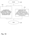
- Fig. 30 illustrates a flow diagram of steps of an embodiment of a method for authentication of a synthetic-image device.
- the method starts in step 200.
- a synthetic-image device is illuminated by a light source emitting divergent rays.
- the synthetic-image device comprises a focusing element array and an image layer.
- the image layer is arranged in a vicinity of a focal distance of focusing elements of the focusing element array.
- the image layer comprises image objects.
- the illumination is performed from a short distance. The short distance is preferably less than 10 cm.
- step 272 occurring during the illumination of step 270, any appearance of a synthetic image not being present without the illumination, is observed as sign of authenticity.
- the procedure ends in step 299.
- Figs. 22-30 can be utilized in single synthetic image applications. However, these configurations can also be utilized as at least one of the first and second synthetic images as mentioned in connection with Figs. 9-21 .
Landscapes
- Physics & Mathematics (AREA)
- General Physics & Mathematics (AREA)
- Engineering & Computer Science (AREA)
- Theoretical Computer Science (AREA)
- Optics & Photonics (AREA)
- Business, Economics & Management (AREA)
- Accounting & Taxation (AREA)
- Marketing (AREA)
- Computer Hardware Design (AREA)
- Nonlinear Science (AREA)
- Chemical & Material Sciences (AREA)
- General Engineering & Computer Science (AREA)
- Crystallography & Structural Chemistry (AREA)
- Human Computer Interaction (AREA)
- Multimedia (AREA)
- Signal Processing (AREA)
- Mathematical Physics (AREA)
- Stereoscopic And Panoramic Photography (AREA)
- Credit Cards Or The Like (AREA)
- Processing Or Creating Images (AREA)
- Image Processing (AREA)
- Focusing (AREA)
- Casting Or Compression Moulding Of Plastics Or The Like (AREA)
- Ink Jet (AREA)
- Cameras In General (AREA)
Claims (11)
- Synthetische Bildvorrichtung (1), umfassendeine Bildschicht (10); undeine Anordnung (20) von fokussierenden Elementen;wobei die Bildschicht (10) in der Nähe einer Brennweite der fokussierenden Elemente (22) der Anordnung (20) von fokussierenden Elementen angeordnet ist;wobei zusammengesetzte Bildobjekte (36) der Bildschicht (10) eine bedingte Zusammenfügung mindestens eines ersten Satzes (31) von Bildobjekten (12), eines Umhüllungsbereichs (35), der dem ersten Satz (31) von Bildobjekten (12) zugeordnet ist, und eines zweiten Satzes (32) von Bildobjekten (12) ist;wobei der erste Satz (31) von Bildobjekten (12) angeordnet ist, um mindestens ein erstes synthetische Bild auf einer Höhe oder Tiefe ungleich Null hervorzubringen, wenn er in der Nähe einer Brennweite von fokussierenden Elementen (22) platziert wird und durch die Anordnung (20) von fokussierenden Elementen hindurch gesehen wird, und wobei der zweite Satz (32) von Bildobjekten (12) angeordnet ist, um mindestens ein zweites synthetisches Bild auf einer Höhe oder Tiefe ungleich Null hervorzubringen, wenn er in der Nähe einer Brennweite von fokussierenden Elementen (22) platziert wird und durch die Anordnung (20) von fokussierenden Elementen hindurch gesehen wird, wobei das erste synthetische Bild und das zweite synthetische Bild auf verschiedenen Höhen/Tiefen bereitgestellt werden und sich in gewissen Blickwinkeln verdecken;wobei der Umhüllungsbereich (35) des ersten Satzes (31) von Bildobjekten (12) ein Bereich ist, der den ersten Satz (32) von Bildobjekten (12) verdeckt und ferner einen Randbereich (34; 34B) umfasst, der den ersten Satz (31) von Bildobjekten (12) nicht verdeckt;wobei die bedingte Zusammenfügung darin besteht, dass die zusammengesetzten Bildobjekte (36) nur in Punkten, in denen der erste Satz (31) von Bildobjekten (12) existiert, oder in Punkten, in denen der zweite Satz (32) von Bildobjekten (12) existiert, aber der Umhüllungsbereich (35), der dem ersten Satz (31) von Bildobjekten (12) zugeordnet ist, nicht existiert, vorhanden sind.
- Synthetische Bildvorrichtung nach Anspruch 1, dadurch gekennzeichnet, dass der Umhüllungsbereich (35) eine Hauptform aufweist, die mit einer Umhüllung der Bildobjekte (12) des ersten Satzes (31) von Bildobjekten (12) deckungsgleich ist.
- Synthetische Bildvorrichtung nach Anspruch 1 oder 2, dadurch gekennzeichnet, dass mindestens eines von dem ersten synthetischen Bild und dem zweiten synthetischen Bild ein integrales synthetisches Bild ist.
- Synthetische Bildvorrichtung nach Anspruch 3, dadurch gekennzeichnet, dass das erste synthetische Bild ein integrales synthetisches Bild ist.
- Synthetische Bildvorrichtung nach einem der Ansprüche 1 bis 4, dadurch gekennzeichnet, dass
mindestens eines von dem ersten synthetischen Bild und dem zweiten synthetischen Bild ein dreidimensionales Bild ist. - Synthetische Bildvorrichtung nach einem der Ansprüche 1 bis 5, dadurch gekennzeichnet, dassder erste Satz (31) von Bildobjekten (12) in einem Satz von ersten Zellen (16) bereitgestellt wird, wobei jede erste Zelle (16) einem jeweiligen fokussierenden Element (22) der Anordnung (20) von fokussierenden Elementen zugeordnet ist; undder Randbereich (35) die Kanten des ersten Satzes (31) von Bildobjekten (12) einschließt, die nicht mit den Grenzen der ersten Zellen (16) zusammenfallen.
- Synthetische Bildvorrichtung nach Anspruch 6, dadurch gekennzeichnet, dass eine mittlere Breite der Objekte des Randbereichs (34) in dem Bereich von 0,1 % bis 10 % eines Durchmessers der fokussierenden Elemente (22) liegt.
- Synthetische Bildvorrichtung nach einem der Ansprüche 1 bis 7, dadurch gekennzeichnet, dass
mindestens einer von dem ersten Satz (31) von Bildobjekten (12) das erste synthetische Bild hervorbringt, wenn er durch die Anordnung (20) von fokussierenden Elementen hindurch aus einer Entfernung von weniger als 15 cm gesehen wird, und von dem zweiten Satz (32) von Bildobjekten (12) das zweite synthetische Bild hervorbringt, wenn er durch die Anordnung (20) von fokussierenden Elementen hindurch aus der Entfernung von weniger als 15 cm gesehen wird. - Synthetische Bildvorrichtung nach einem der Ansprüche 1 bis 8, dadurch gekennzeichnet, dass
mindestens einer von dem ersten Satz (31) von Bildobjekten (12) das erste synthetische Bild hervorbringt, wenn er durch die gebogene Anordnung (20) von fokussierenden Elementen hindurch gesehen wird, und von dem zweiten Satz (32) von Bildobjekten (12) das zweite synthetische Bild hervorbringt, wenn er durch die gebogene Anordnung (20) von fokussierenden Elementen hindurch gesehen wird. - Synthetische Bildvorrichtung nach einem der Ansprüche 1 bis 9, dadurch gekennzeichnet, dassdie zusammengesetzten Bildobjekte (36) der Bildschicht (10) ferner von mindestens einem zusätzlichen Satz (31B, 32B) der Bildobjekte (12) abhängig sind;der zusätzliche Satz (31B, 32B) von Bildobjekten (12) ein zusätzliches synthetisches Bild hervorbringt, wenn er in der Nähe einer Brennweite von fokussierenden Elementen (22) platziert wird und durch die Anordnung (20) von fokussierenden Elementen gesehen wird.
- Verfahren zum Herstellen einer synthetischen Bildvorrichtung, umfassend folgende Schritte:- Erstellen (210) einer numerischen Darstellung eines ersten Satzes von Bildobjekten, die angeordnet sind, um mindestens ein erstes synthetisches Bild auf einer Höhe oder Tiefe ungleich Null hervorzubringen, wenn er in der Nähe einer Brennweite von fokussierenden Elementen platziert wird und durch die Anordnung von fokussierenden Elementen hindurch gesehen wird;- Erstellen (211) einer numerischen Darstellung eines Umhüllungsbereichs, der dem ersten Satz von Bildobjekten zugeordnet ist;- Erstellen (220) einer numerischen Darstellung eines zweiten Satzes von Bildobjekten, die angeordnet sind, um mindestens ein zweites synthetisches Bild auf einer Höhe oder Tiefe ungleich Null hervorzubringen, wenn er in der Nähe einer Brennweite der fokussierenden Elemente angeordnet ist und durch die Anordnung von fokussierenden Elementen hindurch gesehen wird;wobei der Umhüllungsbereich des ersten Satzes von Bildobjekten ein Bereich ist, der den ersten Satz von Bildobjekten verdeckt, und ferner einen Randbereich umfasst, der den ersten Satz von Bildobjekten nicht verdeckt;- Zusammenfügen (230) der numerischen Darstellung des ersten Satzes von Bildobjekten, der numerischen Darstellung des Umhüllungsbereichs der dem ersten Satz von Bildobjekten zugeordnet ist, und der numerischen Darstellung des zweiten Satzes von Bildobjekten gemäß einer vorbestimmten Bedingung zu einer numerischen Darstellung von zusammengesetzten Bildobjekten;wobei das bedingte Zusammenfügen darin besteht, dass die zusammengesetzten Bildobjekte nur in Punkten, in denen der erste Satz von Bildobjekten existiert, oder in Punkten, in denen der zweite Satz von Bildobjekten existiert, aber der Umhüllungsbereich, der dem ersten Satz von Bildobjekten zugeordnet ist, nicht existiert, vorhanden sind,- Bilden (240) einer Bildschicht gemäß der numerischen Darstellung von zusammengesetzten Bildobjekten; und- Bilden (250) einer Anordnung von fokussierenden Elementen;wobei die Bildschicht in der Nähe einer Brennweite der fokussierenden Elemente der Anordnung von fokussierenden Elementen angeordnet ist.
Applications Claiming Priority (2)
| Application Number | Priority Date | Filing Date | Title |
|---|---|---|---|
| SE1650830 | 2016-06-14 | ||
| PCT/SE2017/050598 WO2017217910A1 (en) | 2016-06-14 | 2017-06-07 | Synthetic image and method for manufacturing thereof |
Publications (4)
| Publication Number | Publication Date |
|---|---|
| EP3469574A1 EP3469574A1 (de) | 2019-04-17 |
| EP3469574A4 EP3469574A4 (de) | 2020-02-26 |
| EP3469574C0 EP3469574C0 (de) | 2025-02-19 |
| EP3469574B1 true EP3469574B1 (de) | 2025-02-19 |
Family
ID=60663561
Family Applications (2)
| Application Number | Title | Priority Date | Filing Date |
|---|---|---|---|
| EP17813690.9A Pending EP3469575A4 (de) | 2016-06-14 | 2017-06-07 | Synthetisches bild und verfahren zur herstellung davon |
| EP17813689.1A Active EP3469574B1 (de) | 2016-06-14 | 2017-06-07 | Synthetisches bild und verfahren zur herstellung davon |
Family Applications Before (1)
| Application Number | Title | Priority Date | Filing Date |
|---|---|---|---|
| EP17813690.9A Pending EP3469575A4 (de) | 2016-06-14 | 2017-06-07 | Synthetisches bild und verfahren zur herstellung davon |
Country Status (8)
| Country | Link |
|---|---|
| US (2) | US20190137774A1 (de) |
| EP (2) | EP3469575A4 (de) |
| CN (2) | CN109690664B (de) |
| AU (2) | AU2017285888B2 (de) |
| BR (2) | BR112018075771A2 (de) |
| MX (2) | MX2018015403A (de) |
| RU (2) | RU2735480C2 (de) |
| WO (2) | WO2017217910A1 (de) |
Families Citing this family (5)
| Publication number | Priority date | Publication date | Assignee | Title |
|---|---|---|---|---|
| DE102018010078A1 (de) | 2018-12-20 | 2020-06-25 | Giesecke+Devrient Currency Technology Gmbh | Optisch variables Sicherheitselement |
| GB2594474B (en) * | 2020-04-28 | 2022-05-11 | Koenig & Bauer Banknote Solutions Sa | Methods for designing and producing a security feature |
| KR20230116928A (ko) * | 2020-12-11 | 2023-08-04 | 롤링 옵틱스 이노베이션 에이비 | 연속적인 애니메이션을 갖는 합성 이미지 제조 |
| SE2150453A1 (en) * | 2021-04-13 | 2022-10-14 | Rolling Optics Innovations Ab | Synthetic images with animation of perceived depth |
| SE2451117A1 (en) * | 2024-11-07 | 2025-12-16 | Rolling Optics Innovation Ab | Synthetic image device and manufacturing method therefore |
Citations (7)
| Publication number | Priority date | Publication date | Assignee | Title |
|---|---|---|---|---|
| WO2007076952A2 (de) | 2005-12-23 | 2007-07-12 | Giesecke & Devrient Gmbh | Sicherheitselement |
| WO2009000527A1 (de) | 2007-06-25 | 2008-12-31 | Giesecke & Devrient Gmbh | Darstellungsanordnung |
| WO2009017824A2 (en) | 2007-08-01 | 2009-02-05 | Technical Graphics, Inc. | Improved micro-optic security device |
| WO2010057831A1 (en) | 2008-11-18 | 2010-05-27 | Rolling Optics Ab | Image foils providing a synthetic integral image |
| WO2010094691A1 (en) | 2009-02-20 | 2010-08-26 | Rolling Optics Ab | Devices for integral images and manufacturing method therefore |
| EP2542420B1 (de) | 2010-03-01 | 2014-09-24 | De La Rue International Limited | Moiré-vergrösserungsvorrichtung |
| EP2038692B1 (de) | 2006-06-28 | 2016-04-20 | Visual Physics, LLC | Mikrooptisches sicherheits- und bilddarstellungssystem |
Family Cites Families (19)
| Publication number | Priority date | Publication date | Assignee | Title |
|---|---|---|---|---|
| US5695346A (en) * | 1989-12-07 | 1997-12-09 | Yoshi Sekiguchi | Process and display with moveable images |
| JP3363647B2 (ja) * | 1995-03-01 | 2003-01-08 | キヤノン株式会社 | 画像表示装置 |
| CN1126970C (zh) * | 1996-01-17 | 2003-11-05 | 布鲁斯·A·罗森塔尔 | 豆荚状光学系统 |
| US6373637B1 (en) * | 2000-09-13 | 2002-04-16 | Eastman Kodak Company | Diagonal lenticular image system |
| US6574047B2 (en) * | 2001-08-15 | 2003-06-03 | Eastman Kodak Company | Backlit display for selectively illuminating lenticular images |
| RU2224273C2 (ru) * | 2001-09-11 | 2004-02-20 | Голенко Георгий Георгиевич | Устройство голенко для получения объемного изображения объектов |
| CA2581612A1 (en) * | 2003-09-22 | 2005-04-07 | Gene Dolgoff | Omnidirectional lenticular and barrier-grid image display |
| US8773763B2 (en) * | 2003-11-21 | 2014-07-08 | Visual Physics, Llc | Tamper indicating optical security device |
| SE535491C2 (sv) * | 2010-06-21 | 2012-08-28 | Rolling Optics Ab | Metod och anordning för att läsa optiska anordningar |
| KR101174076B1 (ko) * | 2010-08-31 | 2012-08-16 | 유한회사 마스터이미지쓰리디아시아 | 사선 방향 패럴랙스 베리어 방식 입체영상 표시 장치 |
| KR101723235B1 (ko) * | 2010-10-04 | 2017-04-04 | 삼성전자주식회사 | 입체 영상의 입체감을 감쇠하기 위한 장치 및 방법 |
| JP2012103289A (ja) * | 2010-11-05 | 2012-05-31 | Shiseido Co Ltd | 立体画像の映写構造 |
| TWI540538B (zh) * | 2011-10-27 | 2016-07-01 | 晨星半導體股份有限公司 | 對立體影像之處理方法 |
| US9113059B2 (en) * | 2011-11-30 | 2015-08-18 | Canon Kabushiki Kaisha | Image pickup apparatus and image region discrimination method |
| DE102012205164B4 (de) * | 2012-03-29 | 2021-09-09 | Fraunhofer-Gesellschaft zur Förderung der angewandten Forschung e.V. | Projektionsdisplay und Verfahren zur Projektion virtueller Bilder |
| ES2937647T3 (es) * | 2012-04-25 | 2023-03-30 | Visual Physics Llc | Dispositivo de seguridad para proyectar una colección de imágenes sintéticas |
| JP2013231873A (ja) * | 2012-04-27 | 2013-11-14 | Panasonic Corp | 映像表示装置 |
| TWI491923B (zh) * | 2012-07-13 | 2015-07-11 | E Lon Optronics Co Ltd | 影像顯示片材 |
| EP2821986A1 (de) * | 2013-07-01 | 2015-01-07 | Roland Wolf | Vorrichtung und Verfahren zur Erzeugung einer räumlichen Tiefenwirkung einer in einer 2D Bildfläche vorliegenden Bildinformation |
-
2017
- 2017-06-07 US US16/308,960 patent/US20190137774A1/en not_active Abandoned
- 2017-06-07 CN CN201780049852.1A patent/CN109690664B/zh active Active
- 2017-06-07 EP EP17813690.9A patent/EP3469575A4/de active Pending
- 2017-06-07 AU AU2017285888A patent/AU2017285888B2/en not_active Expired - Fee Related
- 2017-06-07 RU RU2018145422A patent/RU2735480C2/ru active
- 2017-06-07 RU RU2018145361A patent/RU2736014C2/ru active
- 2017-06-07 WO PCT/SE2017/050598 patent/WO2017217910A1/en not_active Ceased
- 2017-06-07 BR BR112018075771-3A patent/BR112018075771A2/pt active Search and Examination
- 2017-06-07 EP EP17813689.1A patent/EP3469574B1/de active Active
- 2017-06-07 MX MX2018015403A patent/MX2018015403A/es unknown
- 2017-06-07 BR BR112018075740-3A patent/BR112018075740A2/pt active Search and Examination
- 2017-06-07 CN CN201780049853.6A patent/CN109643512B/zh active Active
- 2017-06-07 WO PCT/SE2017/050599 patent/WO2017217911A1/en not_active Ceased
- 2017-06-07 US US16/308,947 patent/US20190313008A1/en not_active Abandoned
- 2017-06-07 MX MX2018015641A patent/MX2018015641A/es unknown
- 2017-06-07 AU AU2017285887A patent/AU2017285887B2/en not_active Expired - Fee Related
Patent Citations (7)
| Publication number | Priority date | Publication date | Assignee | Title |
|---|---|---|---|---|
| WO2007076952A2 (de) | 2005-12-23 | 2007-07-12 | Giesecke & Devrient Gmbh | Sicherheitselement |
| EP2038692B1 (de) | 2006-06-28 | 2016-04-20 | Visual Physics, LLC | Mikrooptisches sicherheits- und bilddarstellungssystem |
| WO2009000527A1 (de) | 2007-06-25 | 2008-12-31 | Giesecke & Devrient Gmbh | Darstellungsanordnung |
| WO2009017824A2 (en) | 2007-08-01 | 2009-02-05 | Technical Graphics, Inc. | Improved micro-optic security device |
| WO2010057831A1 (en) | 2008-11-18 | 2010-05-27 | Rolling Optics Ab | Image foils providing a synthetic integral image |
| WO2010094691A1 (en) | 2009-02-20 | 2010-08-26 | Rolling Optics Ab | Devices for integral images and manufacturing method therefore |
| EP2542420B1 (de) | 2010-03-01 | 2014-09-24 | De La Rue International Limited | Moiré-vergrösserungsvorrichtung |
Also Published As
| Publication number | Publication date |
|---|---|
| EP3469575A1 (de) | 2019-04-17 |
| MX2018015641A (es) | 2019-04-11 |
| AU2017285888A1 (en) | 2019-01-03 |
| CN109690664B (zh) | 2022-03-04 |
| EP3469574A1 (de) | 2019-04-17 |
| RU2735480C2 (ru) | 2020-11-03 |
| EP3469574C0 (de) | 2025-02-19 |
| AU2017285887B2 (en) | 2022-08-11 |
| EP3469575A4 (de) | 2020-02-26 |
| AU2017285887A1 (en) | 2018-12-20 |
| WO2017217911A1 (en) | 2017-12-21 |
| MX2018015403A (es) | 2019-04-11 |
| WO2017217910A1 (en) | 2017-12-21 |
| CN109643512A (zh) | 2019-04-16 |
| AU2017285888B2 (en) | 2022-08-11 |
| EP3469574A4 (de) | 2020-02-26 |
| RU2018145422A3 (de) | 2020-07-14 |
| US20190137774A1 (en) | 2019-05-09 |
| RU2018145361A (ru) | 2020-07-14 |
| RU2018145422A (ru) | 2020-07-14 |
| CN109643512B (zh) | 2021-10-01 |
| BR112018075771A2 (pt) | 2019-03-26 |
| CN109690664A (zh) | 2019-04-26 |
| RU2736014C2 (ru) | 2020-11-11 |
| RU2018145361A3 (de) | 2020-07-14 |
| US20190313008A1 (en) | 2019-10-10 |
| BR112018075740A2 (pt) | 2019-03-26 |
Similar Documents
| Publication | Publication Date | Title |
|---|---|---|
| EP3469574B1 (de) | Synthetisches bild und verfahren zur herstellung davon | |
| CN103260893B (zh) | 具有布置在基底上的光学元件的、用于产生悬浮在基底上方或下方的光斑图像的显示元件 | |
| KR101718168B1 (ko) | 마이크로-광학 보안장치 | |
| CN101687428B (zh) | 描绘装置 | |
| EP3734352B1 (de) | Sicherheitsvorrichtung zur projektion einer sammlung von synthetischen bildern | |
| RU2661743C2 (ru) | Пиксельное преобразование и печать для матриц микролинз, чтобы осуществлять двухосевую активацию изображений | |
| RU2609220C2 (ru) | Объект, содержащий область его поверхности, подходящую для показа множества изображений | |
| WO2018101881A1 (en) | Synthetic-image device with interlock features | |
| EP4323199B1 (de) | Synthetische bilder mit animation der wahrgenommenen tiefe | |
| US12337610B2 (en) | Manufacturing of synthetic images with continuous animation | |
| CN107993561B (zh) | 立体防伪微透镜薄片 | |
| CN114728535B (zh) | 用于光斑图像的显示元件 | |
| JP2018167427A (ja) | 表示体 | |
| HK1187308B (en) | Representation element comprising optical elements arranged on a substrate, for producing an image composed of light spots and suspended above or below the substrate |
Legal Events
| Date | Code | Title | Description |
|---|---|---|---|
| STAA | Information on the status of an ep patent application or granted ep patent |
Free format text: STATUS: THE INTERNATIONAL PUBLICATION HAS BEEN MADE |
|
| PUAI | Public reference made under article 153(3) epc to a published international application that has entered the european phase |
Free format text: ORIGINAL CODE: 0009012 |
|
| STAA | Information on the status of an ep patent application or granted ep patent |
Free format text: STATUS: REQUEST FOR EXAMINATION WAS MADE |
|
| 17P | Request for examination filed |
Effective date: 20190114 |
|
| AK | Designated contracting states |
Kind code of ref document: A1 Designated state(s): AL AT BE BG CH CY CZ DE DK EE ES FI FR GB GR HR HU IE IS IT LI LT LU LV MC MK MT NL NO PL PT RO RS SE SI SK SM TR |
|
| AX | Request for extension of the european patent |
Extension state: BA ME |
|
| DAV | Request for validation of the european patent (deleted) | ||
| DAX | Request for extension of the european patent (deleted) | ||
| A4 | Supplementary search report drawn up and despatched |
Effective date: 20200128 |
|
| RIC1 | Information provided on ipc code assigned before grant |
Ipc: G02B 27/60 20060101ALI20200122BHEP Ipc: G09F 19/14 20060101AFI20200122BHEP Ipc: G02B 30/27 20200101ALI20200122BHEP |
|
| STAA | Information on the status of an ep patent application or granted ep patent |
Free format text: STATUS: EXAMINATION IS IN PROGRESS |
|
| 17Q | First examination report despatched |
Effective date: 20221121 |
|
| GRAP | Despatch of communication of intention to grant a patent |
Free format text: ORIGINAL CODE: EPIDOSNIGR1 |
|
| STAA | Information on the status of an ep patent application or granted ep patent |
Free format text: STATUS: GRANT OF PATENT IS INTENDED |
|
| INTG | Intention to grant announced |
Effective date: 20241017 |
|
| GRAS | Grant fee paid |
Free format text: ORIGINAL CODE: EPIDOSNIGR3 |
|
| GRAA | (expected) grant |
Free format text: ORIGINAL CODE: 0009210 |
|
| STAA | Information on the status of an ep patent application or granted ep patent |
Free format text: STATUS: THE PATENT HAS BEEN GRANTED |
|
| AK | Designated contracting states |
Kind code of ref document: B1 Designated state(s): AL AT BE BG CH CY CZ DE DK EE ES FI FR GB GR HR HU IE IS IT LI LT LU LV MC MK MT NL NO PL PT RO RS SE SI SK SM TR |
|
| REG | Reference to a national code |
Ref country code: GB Ref legal event code: FG4D |
|
| REG | Reference to a national code |
Ref country code: CH Ref legal event code: EP |
|
| REG | Reference to a national code |
Ref country code: IE Ref legal event code: FG4D |
|
| REG | Reference to a national code |
Ref country code: DE Ref legal event code: R096 Ref document number: 602017087884 Country of ref document: DE |
|
| U01 | Request for unitary effect filed |
Effective date: 20250313 |
|
| U07 | Unitary effect registered |
Designated state(s): AT BE BG DE DK EE FI FR IT LT LU LV MT NL PT RO SE SI Effective date: 20250319 |
|
| U20 | Renewal fee for the european patent with unitary effect paid |
Year of fee payment: 9 Effective date: 20250516 |
|
| PG25 | Lapsed in a contracting state [announced via postgrant information from national office to epo] |
Ref country code: RS Free format text: LAPSE BECAUSE OF FAILURE TO SUBMIT A TRANSLATION OF THE DESCRIPTION OR TO PAY THE FEE WITHIN THE PRESCRIBED TIME-LIMIT Effective date: 20250519 |
|
| PG25 | Lapsed in a contracting state [announced via postgrant information from national office to epo] |
Ref country code: PL Free format text: LAPSE BECAUSE OF FAILURE TO SUBMIT A TRANSLATION OF THE DESCRIPTION OR TO PAY THE FEE WITHIN THE PRESCRIBED TIME-LIMIT Effective date: 20250219 |
|
| PG25 | Lapsed in a contracting state [announced via postgrant information from national office to epo] |
Ref country code: ES Free format text: LAPSE BECAUSE OF FAILURE TO SUBMIT A TRANSLATION OF THE DESCRIPTION OR TO PAY THE FEE WITHIN THE PRESCRIBED TIME-LIMIT Effective date: 20250219 |
|
| PGFP | Annual fee paid to national office [announced via postgrant information from national office to epo] |
Ref country code: GB Payment date: 20250515 Year of fee payment: 9 |
|
| PG25 | Lapsed in a contracting state [announced via postgrant information from national office to epo] |
Ref country code: NO Free format text: LAPSE BECAUSE OF FAILURE TO SUBMIT A TRANSLATION OF THE DESCRIPTION OR TO PAY THE FEE WITHIN THE PRESCRIBED TIME-LIMIT Effective date: 20250519 Ref country code: IS Free format text: LAPSE BECAUSE OF FAILURE TO SUBMIT A TRANSLATION OF THE DESCRIPTION OR TO PAY THE FEE WITHIN THE PRESCRIBED TIME-LIMIT Effective date: 20250619 |
|
| PG25 | Lapsed in a contracting state [announced via postgrant information from national office to epo] |
Ref country code: HR Free format text: LAPSE BECAUSE OF FAILURE TO SUBMIT A TRANSLATION OF THE DESCRIPTION OR TO PAY THE FEE WITHIN THE PRESCRIBED TIME-LIMIT Effective date: 20250219 |
|
| PG25 | Lapsed in a contracting state [announced via postgrant information from national office to epo] |
Ref country code: GR Free format text: LAPSE BECAUSE OF FAILURE TO SUBMIT A TRANSLATION OF THE DESCRIPTION OR TO PAY THE FEE WITHIN THE PRESCRIBED TIME-LIMIT Effective date: 20250520 |
|
| PG25 | Lapsed in a contracting state [announced via postgrant information from national office to epo] |
Ref country code: SM Free format text: LAPSE BECAUSE OF FAILURE TO SUBMIT A TRANSLATION OF THE DESCRIPTION OR TO PAY THE FEE WITHIN THE PRESCRIBED TIME-LIMIT Effective date: 20250219 |
|
| PGFP | Annual fee paid to national office [announced via postgrant information from national office to epo] |
Ref country code: CH Payment date: 20250701 Year of fee payment: 9 |
|
| PG25 | Lapsed in a contracting state [announced via postgrant information from national office to epo] |
Ref country code: CZ Free format text: LAPSE BECAUSE OF FAILURE TO SUBMIT A TRANSLATION OF THE DESCRIPTION OR TO PAY THE FEE WITHIN THE PRESCRIBED TIME-LIMIT Effective date: 20250219 |
|
| PG25 | Lapsed in a contracting state [announced via postgrant information from national office to epo] |
Ref country code: SK Free format text: LAPSE BECAUSE OF FAILURE TO SUBMIT A TRANSLATION OF THE DESCRIPTION OR TO PAY THE FEE WITHIN THE PRESCRIBED TIME-LIMIT Effective date: 20250219 |
|
| PLBI | Opposition filed |
Free format text: ORIGINAL CODE: 0009260 |
|
| PLAX | Notice of opposition and request to file observation + time limit sent |
Free format text: ORIGINAL CODE: EPIDOSNOBS2 |