EP3468874B1 - Intégration d'un matériau à changement de phase pour limiter la température du carburant à partir d'un module électronique - Google Patents
Intégration d'un matériau à changement de phase pour limiter la température du carburant à partir d'un module électronique Download PDFInfo
- Publication number
- EP3468874B1 EP3468874B1 EP17736986.5A EP17736986A EP3468874B1 EP 3468874 B1 EP3468874 B1 EP 3468874B1 EP 17736986 A EP17736986 A EP 17736986A EP 3468874 B1 EP3468874 B1 EP 3468874B1
- Authority
- EP
- European Patent Office
- Prior art keywords
- fuel
- heat
- electronic module
- phase change
- temperature
- Prior art date
- Legal status (The legal status is an assumption and is not a legal conclusion. Google has not performed a legal analysis and makes no representation as to the accuracy of the status listed.)
- Active
Links
Images



Classifications
-
- F—MECHANICAL ENGINEERING; LIGHTING; HEATING; WEAPONS; BLASTING
- F02—COMBUSTION ENGINES; HOT-GAS OR COMBUSTION-PRODUCT ENGINE PLANTS
- F02C—GAS-TURBINE PLANTS; AIR INTAKES FOR JET-PROPULSION PLANTS; CONTROLLING FUEL SUPPLY IN AIR-BREATHING JET-PROPULSION PLANTS
- F02C7/00—Features, components parts, details or accessories, not provided for in, or of interest apart form groups F02C1/00 - F02C6/00; Air intakes for jet-propulsion plants
- F02C7/22—Fuel supply systems
- F02C7/224—Heating fuel before feeding to the burner
-
- B—PERFORMING OPERATIONS; TRANSPORTING
- B64—AIRCRAFT; AVIATION; COSMONAUTICS
- B64D—EQUIPMENT FOR FITTING IN OR TO AIRCRAFT; FLIGHT SUITS; PARACHUTES; ARRANGEMENT OR MOUNTING OF POWER PLANTS OR PROPULSION TRANSMISSIONS IN AIRCRAFT
- B64D37/00—Arrangements in connection with fuel supply for power plant
- B64D37/34—Conditioning fuel, e.g. heating
-
- F—MECHANICAL ENGINEERING; LIGHTING; HEATING; WEAPONS; BLASTING
- F02—COMBUSTION ENGINES; HOT-GAS OR COMBUSTION-PRODUCT ENGINE PLANTS
- F02C—GAS-TURBINE PLANTS; AIR INTAKES FOR JET-PROPULSION PLANTS; CONTROLLING FUEL SUPPLY IN AIR-BREATHING JET-PROPULSION PLANTS
- F02C9/00—Controlling gas-turbine plants; Controlling fuel supply in air- breathing jet-propulsion plants
- F02C9/26—Control of fuel supply
- F02C9/263—Control of fuel supply by means of fuel metering valves
-
- H—ELECTRICITY
- H10—SEMICONDUCTOR DEVICES; ELECTRIC SOLID-STATE DEVICES NOT OTHERWISE PROVIDED FOR
- H10W—GENERIC PACKAGES, INTERCONNECTIONS, CONNECTORS OR OTHER CONSTRUCTIONAL DETAILS OF DEVICES COVERED BY CLASS H10
- H10W40/00—Arrangements for thermal protection or thermal control
- H10W40/20—Arrangements for cooling
- H10W40/22—Arrangements for cooling characterised by their shape, e.g. having conical or cylindrical projections
-
- H—ELECTRICITY
- H10—SEMICONDUCTOR DEVICES; ELECTRIC SOLID-STATE DEVICES NOT OTHERWISE PROVIDED FOR
- H10W—GENERIC PACKAGES, INTERCONNECTIONS, CONNECTORS OR OTHER CONSTRUCTIONAL DETAILS OF DEVICES COVERED BY CLASS H10
- H10W40/00—Arrangements for thermal protection or thermal control
- H10W40/20—Arrangements for cooling
- H10W40/25—Arrangements for cooling characterised by their materials
- H10W40/255—Arrangements for cooling characterised by their materials having a laminate or multilayered structure, e.g. direct bond copper [DBC] ceramic substrates
-
- H—ELECTRICITY
- H10—SEMICONDUCTOR DEVICES; ELECTRIC SOLID-STATE DEVICES NOT OTHERWISE PROVIDED FOR
- H10W—GENERIC PACKAGES, INTERCONNECTIONS, CONNECTORS OR OTHER CONSTRUCTIONAL DETAILS OF DEVICES COVERED BY CLASS H10
- H10W40/00—Arrangements for thermal protection or thermal control
- H10W40/70—Fillings or auxiliary members in containers or in encapsulations for thermal protection or control
- H10W40/73—Fillings or auxiliary members in containers or in encapsulations for thermal protection or control for cooling by change of state
-
- H—ELECTRICITY
- H10—SEMICONDUCTOR DEVICES; ELECTRIC SOLID-STATE DEVICES NOT OTHERWISE PROVIDED FOR
- H10W—GENERIC PACKAGES, INTERCONNECTIONS, CONNECTORS OR OTHER CONSTRUCTIONAL DETAILS OF DEVICES COVERED BY CLASS H10
- H10W90/00—Package configurations
-
- F—MECHANICAL ENGINEERING; LIGHTING; HEATING; WEAPONS; BLASTING
- F05—INDEXING SCHEMES RELATING TO ENGINES OR PUMPS IN VARIOUS SUBCLASSES OF CLASSES F01-F04
- F05D—INDEXING SCHEME FOR ASPECTS RELATING TO NON-POSITIVE-DISPLACEMENT MACHINES OR ENGINES, GAS-TURBINES OR JET-PROPULSION PLANTS
- F05D2260/00—Function
- F05D2260/20—Heat transfer, e.g. cooling
- F05D2260/207—Heat transfer, e.g. cooling using a phase changing mass, e.g. heat absorbing by melting or boiling
-
- F—MECHANICAL ENGINEERING; LIGHTING; HEATING; WEAPONS; BLASTING
- F05—INDEXING SCHEMES RELATING TO ENGINES OR PUMPS IN VARIOUS SUBCLASSES OF CLASSES F01-F04
- F05D—INDEXING SCHEME FOR ASPECTS RELATING TO NON-POSITIVE-DISPLACEMENT MACHINES OR ENGINES, GAS-TURBINES OR JET-PROPULSION PLANTS
- F05D2260/00—Function
- F05D2260/20—Heat transfer, e.g. cooling
- F05D2260/213—Heat transfer, e.g. cooling by the provision of a heat exchanger within the cooling circuit
-
- H—ELECTRICITY
- H10—SEMICONDUCTOR DEVICES; ELECTRIC SOLID-STATE DEVICES NOT OTHERWISE PROVIDED FOR
- H10W—GENERIC PACKAGES, INTERCONNECTIONS, CONNECTORS OR OTHER CONSTRUCTIONAL DETAILS OF DEVICES COVERED BY CLASS H10
- H10W70/00—Package substrates; Interposers; Redistribution layers [RDL]
- H10W70/40—Leadframes
- H10W70/479—Leadframes on or in insulating or insulated package substrates, interposers, or redistribution layers
-
- H—ELECTRICITY
- H10—SEMICONDUCTOR DEVICES; ELECTRIC SOLID-STATE DEVICES NOT OTHERWISE PROVIDED FOR
- H10W—GENERIC PACKAGES, INTERCONNECTIONS, CONNECTORS OR OTHER CONSTRUCTIONAL DETAILS OF DEVICES COVERED BY CLASS H10
- H10W72/00—Interconnections or connectors in packages
- H10W72/071—Connecting or disconnecting
- H10W72/075—Connecting or disconnecting of bond wires
- H10W72/07551—Connecting or disconnecting of bond wires characterised by changes in properties of the bond wires during the connecting
- H10W72/07554—Connecting or disconnecting of bond wires characterised by changes in properties of the bond wires during the connecting changes in dispositions
-
- H—ELECTRICITY
- H10—SEMICONDUCTOR DEVICES; ELECTRIC SOLID-STATE DEVICES NOT OTHERWISE PROVIDED FOR
- H10W—GENERIC PACKAGES, INTERCONNECTIONS, CONNECTORS OR OTHER CONSTRUCTIONAL DETAILS OF DEVICES COVERED BY CLASS H10
- H10W72/00—Interconnections or connectors in packages
- H10W72/50—Bond wires
- H10W72/541—Dispositions of bond wires
- H10W72/547—Dispositions of multiple bond wires
-
- H—ELECTRICITY
- H10—SEMICONDUCTOR DEVICES; ELECTRIC SOLID-STATE DEVICES NOT OTHERWISE PROVIDED FOR
- H10W—GENERIC PACKAGES, INTERCONNECTIONS, CONNECTORS OR OTHER CONSTRUCTIONAL DETAILS OF DEVICES COVERED BY CLASS H10
- H10W72/00—Interconnections or connectors in packages
- H10W72/851—Dispositions of multiple connectors or interconnections
- H10W72/874—On different surfaces
- H10W72/884—Die-attach connectors and bond wires
-
- H—ELECTRICITY
- H10—SEMICONDUCTOR DEVICES; ELECTRIC SOLID-STATE DEVICES NOT OTHERWISE PROVIDED FOR
- H10W—GENERIC PACKAGES, INTERCONNECTIONS, CONNECTORS OR OTHER CONSTRUCTIONAL DETAILS OF DEVICES COVERED BY CLASS H10
- H10W90/00—Package configurations
- H10W90/701—Package configurations characterised by the relative positions of pads or connectors relative to package parts
- H10W90/751—Package configurations characterised by the relative positions of pads or connectors relative to package parts of bond wires
- H10W90/753—Package configurations characterised by the relative positions of pads or connectors relative to package parts of bond wires between laterally-adjacent chips
-
- H—ELECTRICITY
- H10—SEMICONDUCTOR DEVICES; ELECTRIC SOLID-STATE DEVICES NOT OTHERWISE PROVIDED FOR
- H10W—GENERIC PACKAGES, INTERCONNECTIONS, CONNECTORS OR OTHER CONSTRUCTIONAL DETAILS OF DEVICES COVERED BY CLASS H10
- H10W90/00—Package configurations
- H10W90/701—Package configurations characterised by the relative positions of pads or connectors relative to package parts
- H10W90/751—Package configurations characterised by the relative positions of pads or connectors relative to package parts of bond wires
- H10W90/754—Package configurations characterised by the relative positions of pads or connectors relative to package parts of bond wires between a chip and a stacked insulating package substrate, interposer or RDL
-
- Y—GENERAL TAGGING OF NEW TECHNOLOGICAL DEVELOPMENTS; GENERAL TAGGING OF CROSS-SECTIONAL TECHNOLOGIES SPANNING OVER SEVERAL SECTIONS OF THE IPC; TECHNICAL SUBJECTS COVERED BY FORMER USPC CROSS-REFERENCE ART COLLECTIONS [XRACs] AND DIGESTS
- Y02—TECHNOLOGIES OR APPLICATIONS FOR MITIGATION OR ADAPTATION AGAINST CLIMATE CHANGE
- Y02T—CLIMATE CHANGE MITIGATION TECHNOLOGIES RELATED TO TRANSPORTATION
- Y02T50/00—Aeronautics or air transport
- Y02T50/60—Efficient propulsion technologies, e.g. for aircraft
Definitions
- the invention relates to the supply of fuel to an engine group, and in particular to the management of the fuel phase state.
- the invention relates to power units comprising a heat engine and an electric machine.
- “Turbine heat engine” means, in the present context, any machine allowing the conversion of the thermal energy of a working fluid into mechanical energy by expansion of said working fluid in a turbine.
- this working fluid can be a combustion gas resulting from the chemical reaction of a fuel with air in a combustion chamber, after the compression of this air in a compressor actuated by the turbine through a first rotating shaft.
- turbine thermal engines include single or double flow turbojets, turbopropellers, turboshaft engines or gas turbines, among others.
- upstream and downstream are defined with respect to the normal direction of circulation of the working fluid in the turbomachine.
- the fuel supplying turbine thermal engines may include impurities, and in particular water in suspension. At normal temperatures the presence of traces of water in the fuel is not very problematic. However, when temperatures are low, this water may freeze. The resulting ice particles can possibly block the passage of fuel, in particular by agglomerating at the inlet of the filters typically used to prevent the passage of other solid impurities. Consequently, this icing in the fuel system should be avoided.
- a first solution against fuel freezing consists in adding additives, which are expensive, toxic and restrictive. This solution is deliberately discarded.
- a second solution consists, as presented in the document US 20120240593 , to recover the heat given off by an electronic circuit, in this case an electronic power conversion circuit (GCU for “ Generator Control Unit ”), to heat the fuel and prevent it from freezing.
- GCU Generator Control Unit
- a heat exchanger makes it possible to carry out heat transfers.
- the GCU then functions as a radiator.
- the management of the heat transfer between the GCU and the fuel is done by controlling the fluid flow rate, or by adding an additional dedicated electric radiator, which allows on the one hand to generate additional heat and by asking more of the GCU, which in turn heats up more.
- the PCM material ensures the temperature rise is better diffused over time, which makes it possible to limit the temperature peaks and thus avoid reaching the vaporization temperature of the petrol.
- the PCM material protects the electronic module from these temperature peaks which can damage it.
- the PCM material thus distributes the heat flow in an optimized manner between the electronic module and the fuel.
- the phase change temperature of the PCM material is chosen so as to be lower than the vaporization temperature of said fuel which circulates in the fuel supply circuit.
- the energy source is advantageously an electric machine capable of operating as a motor or generator and in which the electric machine is mechanically coupled to a rotating shaft of the heat engine.
- the invention also provides a method of heating fuel using an engine assembly or group as described above, in which the fuel is heated, in the heat exchanger of the fuel supply circuit. by the heat emitted by the electronic module through the PCM phase change material.
- the invention also proposes the use of PCM phase change material to control the heat transfer between on the one hand an electronic module releasing heat when it is supplied with energy, and on the other hand a turbine fuel gas, through a heat exchanger.
- the fuel supply circuit 15 has the function of supplying a turbine engine with fuel. Specific embodiments will be detailed later.
- the electronic module 14 generally comprises at least one electronic circuit on which are connected electronic components capable of processing electrical signals (information or energy). Consequently, when it is requested by the energy source 13, the module 14 gives off heat.
- a heat exchanger 16 is provided. Typically, the heat exchanger 16 is positioned between the electronic module 14 and the fuel supply circuit 15a, 15b.
- the heat exchanger 16 makes it possible to optimize the heat flow between the module 14 and the supply circuit 15. It can take different forms, such as a plate exchanger, with fins, or simply in the form of branching of pipes favoring the 'heat exchange.
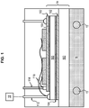
- the electronic module 14 comprises in one embodiment a base substrate 100 forming a support on which electronic components 110 are fixed, such as bipolar insulated gate transistors, diodes, capacitors, inductors, etc. As shown in figure 1 , these components 110 may require transmitters 112, doors 114, a collector 116 and connecting wires 118 for example.
- Different layers of material such as a brazed joint 102, a copper sole 104, another insulating substrate 106, for example ceramic, to make interconnections between the semiconductors and with external circuits on the copper sole 104 , are conventionally provided for the operation of the electronic module.
- the electronic module 14 includes a phase change material, referenced PCM for " Phase-change material ".
- PCM phase change material
- the figure 2 shows various embodiments detailed below.
- PCM materials change state, usually from solid to liquid, as soon as their melting temperature is reached.
- PCM materials which change phase from a solid or liquid state to a gaseous state, we speak more generally of phase change temperature Tf. This temperature Tf is a characteristic of the PCM material.
- the demand for electrical power from an electrical system can be very high over times which do not exceed a few tens of seconds or even a minute.
- the use of PCM materials allows better thermal management as close as possible to critical 110 electronic components such as static components, capacitors, inductors, etc. Indeed, reaching its melting temperature therefore by passing from the solid state to the liquid state, the PCM material will absorb a quantity of heat while remaining at the same temperature (by the time the entire material has changed state ) and a thermal transfer will then take place between the electronic components 110 inside the electronic module 14 and this PCM material.
- This absorption is linked to the enthalpy of change of state of the material PCM, also called latent heat, which corresponds to the energy which a unit of mass of the material must receive to change state.
- the PCM material will then absorb the temperature spike.
- one of the main problems in the development of electronics on board aircraft is that of the temperature resistance of the electronic components 110, in particular those which are soldered / or soldered to the substrate 100.
- the thermomechanical constraints between the component 110 and the substrate 100 can in certain cases cause delamination of the solder or the solder of the component on its substrate, which can destroy the component.
- Such uses of PCM material are already known, as in the document US 20130147050 .
- the PCM material also allows gains in sizing and occupied volume.
- the electronic components 110 such as the transistors, capacitors, inductors, can be dimensioned not on a maximum temperature peak but on an averaged lower temperature.
- the PCM material has a primary role, which is to absorb heat to prevent the electronic module 14 from exceeding a critical temperature.
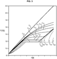
- the figure 3 illustrates this absorption as a function of time: the curve C0 represents the temperature rise of the electronic module 14 in the absence of PCM material, the curves C11 to C18 represent the temperature rise of the electronic module 14 in the presence of PCM material for different thermal resistances between the PCM material and the substrate 100, the curves C23 to C27 represent the temperature rise of the PCM material (in connection with the curves C13 to C17). It is noted that the phase change temperature Tf of the PCM material is slightly less than 120 ° C.
- the electronic module 14 also has the function of heating the fuel.
- power peaks can generate too much heat and that the management of heat transfer is problematic. Consequently, the PCM material, which has absorbed the heat peak, gradually returns it to the exchanger 16a, 16b.
- the PCM material makes it possible to average the heat transfer between the electronic module 14 and the fuel. In this way, the risks of vaporization of said fuel are greatly reduced.
- PCM material in such a heat exchange architecture between the electronic module 14 and the fuel circuit 15 makes it possible to put a thermal barrier which, by diffusing the heat over time, protects the fuel from vaporization, while protecting module 14 from overheating.
- the PCM material is used here as a radiator, from the energy stored via the electronic module 14 .
- a PCM material is chosen whose phase change temperature Tf is lower than the vaporization temperature Tv of the fuel.
- a temperature Tf of less than 150 ° C, preferably 140 ° C, more preferably less than or equal to 130 ° C is suitable.
- the temperature Tf is greater than 120 ° C, to prevent the change of state from being completely performed while the electronic module 14 has not yet reached temperatures which could compromise its operation.
- PCM materials in the electronic module can be done in different ways, as shown on the figure 2 which schematize three variants, not necessarily mutually exclusive.
- the electronic components 110 are encapsulated in the PCM1 material.
- a specific matrix comprising PCM material is used. This variant requires that the electronic components 110 be waterproof.
- the PCM2 material can be integrated into the substrate 100.
- the document is known in particular US2013 / 0147050 which discloses such integration in the substrate 100.
- a specific volume must then be arranged in the substrate 100.
- a cold plate 120 is provided against the substrate 110, on the side opposite to the electronic components 110.
- the cold plate 120 is therefore positioned between the heat exchanger 16 and the base substrate 100.
- the cold plate 120 has the function of promoting the cooling of the electronic module 14.
- the PCM3 material is then integrated into this cold plate 120.
- the relative positioning of the fuel circuit and the base substrate and / or the cold plate can be adapted.
- the heat exchanger can be housed in the base substrate 100 or in the cold plate 120.
- the exchanger can then take the form of a fluid circuit, such as a branching of a pipe, arranged in the plate.
- the circulation of the fluid is then preferably forced by a dedicated pump.
- the PCM material can include hydrated salts, paraffins, and / or alcohols.
- PCM materials also lies in the gain in mass and volume compared to other technologies.
- the electronic module 14 is a power module, configured to convert the energy supplied by the energy source. It is therefore particularly subject to temperature rises, in particular during very short times during which it is stressed.
- the electronic components 110 can in particular be power semiconductors.
- the figure 4 illustrates an aircraft 1 with rotary wing, more specifically a helicopter with a main rotor 2 and an anti-torque tail rotor 3 coupled to a power unit 4 for their actuation.
- the engine group 4 illustrated comprises a first heat engine 5a and a second heat engine 5b.
- These heat engines 5a, 5b are turbine heat engines and more specifically turboshaft engines, the power take-off shafts 6 of which are both connected to a main gearbox 7 for actuating the main rotor 2 and the tail rotor 3.
- Each heat engine 5a, 5b comprises a compressor 8, a combustion chamber 9, a first turbine 10 connected by a rotary shaft 11 to the compressor 8 and a second turbine 12, or free turbine, coupled to the power take-off shaft 6
- the assembly of the compressor 8, combustion chamber 9, first turbine 10 and rotary shaft 11 is also known by the name of "gas generator”.
- the rotary shaft 11 of each gas generator is mechanically coupled to the energy source 13a, 13b, which is more specifically an electric machine 13a, 13b generally in the form of a motor generator, electrically connected to the electric module 14a , 14b, which is here an electronic power module, which is more specifically a power converter also electrically connected to an electrical storage device 20 and to an electrical network of the aircraft 1.
- This electrical storage device 20 can for example be a battery, although other electrical storage devices (eg fuel cells or flywheels) are also possible.
- the electric machines 13a, 13b are used both for starting the combustion engines 5a, 5b corresponding to and for generating electricity after this start.
- the electric machine 13a, 13b operates in engine mode, and the power electronics module 14a, 14b provides its electrical supply from the electrical network of the aircraft and / or from the electrical storage device 20.
- the electric machine 13a, 13b operates in generator mode, and the power electronics module 14a, 14b adapts the current generated to a voltage and amperage suitable for supplying the electrical network of the aircraft and / or of the electrical storage device 20.
- each electric machine 13a, 13b can also be used to maintain the corresponding heat engine 5a, 5b in standby mode, even during the flight of the aircraft 1, by rotating its rotary shaft 11, with the combustion 9 extinguished, at a reduced speed Nveille, which can be, for example, between 5 and 20% of a nominal speed N1 of the rotary shaft 11.
- Nveille which can be, for example, between 5 and 20% of a nominal speed N1 of the rotary shaft 11.
- the power supplied by the engine group 4 can vary significantly depending on the flight stage of the aircraft 1.
- the power required for the cruising speed is normally significantly less than the maximum continuous power of the engine group 4, and even less in relation to its maximum take-off power.
- the power unit 4 being dimensioned as a function of the latter, it is appreciably oversized with respect to the power required for the cruising speed. Consequently, when cruising, with the two heat engines 5a, 5b in operation, they could find themselves far from their optimal operating regime, which would result in a relatively high specific consumption.
- an engine group comprising a plurality of heat engines, it is possible to maintain the cruising speed with at least one of these heat engines off.
- the first heat engine 5a is therefore switched off during the cruising speed of the aircraft 1, while the second heat engine 5b supplies all the power to the main rotor 2 and to the tail rotor 3 through the main gearbox 7.
- the electrical machine 13b associated with the second heat engine 5b simultaneously supplies the electrical network of the aircraft 1 through its power electronics module 14b and the electrical machine 13a through its electronics 14a.
- the first heat engine 5a is maintained in standby mode by actuation of its rotary shaft 11 by the corresponding electric machine 13a , powered through its power electronics module 14a.
- each is associated with the fuel supply circuits 15a, 15b, with the heat exchanger 16a, 16b and, moreover, a fuel filter 17a, 17b located downstream of the heat exchanger 16a, 16b in the direction of flow of the fuel to the heat engine 5a, 5b.
- each heat exchanger 16a, 16b is adjacent to a base of the power electronics module 14a, 14b (for example a cold plate 21) corresponding, in a housing 22, which can be sealed and common to the power electronics module 14a, 14b and to the corresponding heat exchanger 16a, 16b, so that the fuel flowing through the heat exchanger 16a or 16b can be heated by heat generated by the operation of the power electronics module 14a, 14b, and simultaneously contribute to the cooling of the power electronics module 14a, 14b to allow it to operate in an optimal temperature range.
- a base of the power electronics module 14a, 14b for example a cold plate 21
- each electronics module of power 14a, 14b can treat a power Pe of the order of 100 kW, with heat losses of less than 10%, thus resulting in a caloric power Ph of, for example, less than 10 kW, or even less than 1 kW .
- each power electronics module 14a, 14b can have a normal operating mode and an operating mode with degraded electrical efficiency which can be implemented to generate additional heat for heating the fuel.
- This operating mode with degraded efficiency can be obtained for example by imposing on semiconductors of the power electronics module 14a, 14b a cutting frequency higher than that which would normally be applied according to the usual electrical dimensioning criteria.
- Each fuel supply circuit 15a, 15b may also include a bypass line 18a, 18b of the heat exchanger 16a, 16b, as well as a three-way valve 19a, 19b for controlling the flow of fuel through the 'heat exchanger 16a, 16b or by the bypass duct 18a, 18b.
- the latter To heat the fuel supplying one of the heat engines 5a, 5b during a start-up of the latter at low temperature before lighting the combustion chamber 9, the latter is directed through the corresponding heat exchanger 16a, 16b, in which it is heated by the heat generated by the operation of the power electronics module 14a, 14b through which the electric machine 13a, 13b is electrically powered to rotate the rotary shaft 11 of this heat engine 5a, 5b.
- the heat generated by the power electronics module 14a, 14b in normal operating mode is insufficient to allow a rapid start without risk of clogging of the fuel filter 17a, 17b by water ice particles, a mode of degraded electrical efficiency operation of the power electronics module 14a, 14b can be implemented to increase the generation of heat in this module, and its transmission, through the heat exchanger 16a, 16b, to the fuel.
- the three-way valve 19a, 19b can direct the fuel through the corresponding bypass pipe 18a, 18b.
Landscapes
- Engineering & Computer Science (AREA)
- Chemical & Material Sciences (AREA)
- Combustion & Propulsion (AREA)
- Mechanical Engineering (AREA)
- General Engineering & Computer Science (AREA)
- Aviation & Aerospace Engineering (AREA)
- Engine Equipment That Uses Special Cycles (AREA)
- Ceramic Engineering (AREA)
- Fuel Cell (AREA)
- Cooling Or The Like Of Semiconductors Or Solid State Devices (AREA)
- Control Of Temperature (AREA)
Description
- L'invention concerne l'alimentation d'un groupe moteur en carburant, et en particulier, la gestion de l'état de phase du carburant.
- Plus spécifiquement, l'invention concerne les groupes moteurs comprenant un moteur thermique et une machine électrique.
- On entend par « moteur thermique à turbine », dans le présent contexte, toute machine permettant la conversion de l'énergie thermique d'un fluide de travail en énergie mécanique par détente dudit fluide de travail dans une turbine.
- Plus particulièrement, ce fluide de travail peut être un gaz de combustion résultant de la réaction chimique d'un carburant avec de l'air dans une chambre de combustion, après la compression de cet air dans un compresseur actionné par la turbine à travers un premier arbre rotatif.
- Ainsi, les moteurs thermiques à turbine, telles que compris dans le présent contexte, comprennent les turboréacteurs à flux simple ou double, les turbopropulseurs, les turbomoteurs ou les turbines à gaz, entre autres.
- Dans la description qui suit, les termes "amont" et "aval" sont définis par rapport au sens de circulation normal du fluide de travail dans la turbomachine.
- Le carburant alimentant des moteurs thermiques à turbine peut comprendre des impuretés, et notamment de l'eau en suspension. A des températures normales la présence de traces d'eau dans le carburant n'est pas très problématique. Toutefois, quand les températures sont basses, cette eau peut geler. Les particules de glace résultantes peuvent éventuellement bloquer le passage du carburant, notamment en s'agglomérant à l'entrée des filtres typiquement utilisés pour empêcher le passage d'autres impuretés solides. En conséquence, il convient d'éviter ce givrage dans le circuit de carburant.
- Une première solution contre le gel du carburant consiste à ajouter des additifs, coûteux, toxiques et contraignants. Cette solution est volontairement écartée.
- Une deuxième solution consiste, comme présenté dans le document
US 20120240593 , à récupérer la chaleur dégagée par un circuit électronique, en l'occurrence un circuit électronique de conversion de puissance (GCU pour « Generator Control Unit »), pour réchauffer le carburant et empêcher que ce dernier ne gèle. Un échangeur de chaleur permet d'effectuer les transferts thermiques. - Le GCU fonctionne alors comme un radiateur.
- Dans le document précité, la gestion du transfert de chaleur entre le GCU et le carburant se fait par contrôle du débit de fluide, ou par ajout d'un radiateur électrique dédié supplémentaire, qui permet d'une part de générer de la chaleur supplémentaire et en de solliciter davantage le GCU, qui à son tour chauffe davantage.
- Néanmoins, il existe un risque, non mentionné dans le document précité, que le carburant reçoive trop d'énergie et puisse atteindre sa température de vaporisation. En effet, certaines électroniques embarquées fonctionnent pendant des durées très courtes, ce qui implique une puissance élevée. En outre, le voltage utilisé, souvent de l'ordre de quelques dizaines de volts, provoque des ampérages très élevées, d'où une génération de chaleur importante.
- Ce phénomène de vaporisation doit être impérativement être évité.
- L'invention vise à remédier aux inconvénients précités en proposant un ensemble comprenant :
- Un circuit d'alimentation en carburant configuré pour alimenter un moteur thermique à turbine en carburant,
- Un module électronique,
- Une source d'énergie pour fournir le module électronique en électricité,
- Un échangeur de chaleur positionné pour permettre un flux de chaleur du module électronique vers le circuit d'alimentation en carburant,
l'ensemble étant caractérisé en ce que le module électronique comprend un matériau à changement de phase (PCM), configuré pour changer d'état lorsque sa température atteint une température prédéterminée de changement de phase. - Grâce au matériau PCM, l'élévation de température est mieux diffusée dans le temps, ce qui permet de limiter les pics de température et ainsi d'éviter d'atteinte la température de vaporisation de l'essence.
De plus, le matériau PCM protège le module électronique de ces pics de température qui peuvent l'endommager.
Le matériau PCM permet ainsi de répartir le flux de chaleur d'une façon optimisée entre le module électronique et le carburant. - Afin d'empêcher le carburant de se vaporiser, la température de changement de phase du matériau PCM est choisie de sorte à être inférieure à la température de vaporisation dudit carburant qui circule dans le circuit d'alimentation en carburant.
- L'invention peut comprendre les caractéristiques suivantes, prises seules ou en combinaison :
- ladite température prédéterminée de changement de phase est inférieure à la température de vaporisation du carburant,
- le module électronique est un module électronique de puissance, configuré pour convertir l'énergie fournie par la source d'énergie,
- la température de changement de phase est inférieure à 150°C, préférablement inférieure à 140°C.
- le module électronique comprend les éléments suivants :
- un substrat de base formant un support,
- des composants électroniques, positionnés sur le support,
- les composants électroniques sont encapsulés dans du matériau à changement de phase PCM,
- du matériau à changement de phase PCM est intégré au substrat de base,
- le module électronique comprend une plaque froide, et dans lequel du matériau à changement de phase est intégré à la plaque froide.
- la plaque froide est positionnée entre le substrat de base et l'échangeur de chaleur,
- l'échangeur de chaleur est intégré à la plaque froide,
- L'invention propose aussi un groupe moteur comprenant :
- Un moteur thermique à turbine,
- Un ensemble tel que décrit précédemment,
dans lequel le circuit d'alimentation en carburant est configuré pour alimenter le moteur thermique. - La source d'énergie est avantageusement une machine électrique pouvant fonctionner en moteur ou en générateur et dans lequel la machine électrique est couplée mécaniquement à un arbre tournant du moteur thermique.
- L'invention propose aussi un procédé de réchauffement de carburant à l'aide d'un ensemble ou d'un groupe moteur tel que décrit précédemment, dans lequel le carburant est chauffé, dans l'échangeur de chaleur du circuit d'alimentation en carburant par la chaleur émise par le module électronique au travers du matériau à changement de phase PCM.
- L'invention propose aussi l'utilisation de matériau à changement de phase PCM pour contrôler le transfert thermique entre d'une part un module électronique dégageant de la chaleur lorsqu'il est alimenté en énergie, et d'autre part un carburant pour turbine à gaz, par le biais d'un échangeur de chaleur.
- D'autres caractéristiques, buts et avantages de l'invention ressortiront de la description qui suit, qui est purement illustrative et non limitative, et qui doit être lue en regard des dessins annexés, sur lesquels :
- la
figure 1 illustre schématiquement un module d'électronique de puissance et un échangeur de chaleur de groupe moteur, représentée sans matériau PCM à des fins de clarté, - la
figure 2 est similaire à lafigure 1 , mais avec trois variantes d'intégration de matériau PCM, et avec un ajout d'une plaque froide, - la
figure 3 représente des courbes de température relatives à l'utilisation de matériau PCM, - la
figure 4 illustre schématiquement un aéronef avec un groupe moteur comportant deux turbomoteurs et deux moteurs-générateurs électriques, - la
figure 5 illustre plus spécifiquement ce groupe moteur. - En référence à la
figure 1 , on définit un ensemble comprenant un circuit d'alimentation en carburant 15, un module électronique 14 et une source d'énergie 13 qui apporte de l'énergie, typiquement de l'électricité au module 14.
Le circuit d'alimentation en carburant15 a pour fonction d'alimenter un moteur thermique à turbine en carburant. Des modes de réalisations particuliers seront détaillés par la suite.
Le module électronique 14 comprend généralement au moins un circuit électronique sur lequel sont reliés entre eux des composants électroniques aptes à traiter des signaux électriques (information ou énergie).
Par conséquent, lorsqu'il est sollicité par la source d'énergie 13, le module 14 dégage de la chaleur. Afin que cette chaleur soit transmise vers le circuit d'alimentation en carburant 15, un échangeur de chaleur 16 est prévu. Typiquement, l'échangeur de chaleur 16 est positionné entre le module électronique 14 et le circuit d'alimentation en carburant 15a, 15b. - L'échangeur de chaleur 16 permet d'optimiser le flux thermique entre le module 14 et le circuit d'alimentation 15. Il peut prendre différentes formes, comme un échangeur à plaques, à ailettes, ou simplement sous forme de ramifications de tuyaux favorisant l'échange thermique.
- Le module électronique 14 comprend dans un mode de réalisation un substrat de base 100 formant support sur lequel sont fixé des composants électroniques 110, comme des transistors bipolaire à grille isolée, des diodes, des condensateurs, des inductances, etc. Comme représenté en
figure 1 , ces composants 110 peuvent nécessiter des émetteurs 112, des portes 114, un collecteur 116 et des fils de liaisons 118 par exemple.
Différentes couches de matériaux, comme un joint brasé 102, une semelle en cuivre 104, un autre substrat d'isolation 106, par exemple en céramique, pour réaliser des interconnexions entre les semi-conducteurs et avec des circuits externes sur la semelle en cuivre 104, sont classiquement prévues pour le fonctionnement du module électronique. - Afin de mieux réguler le transfert d'énergie, le module électronique 14 comprend un matériau à changement de phase, référencé PCM pour « Phase-change material ». La
figure 2 représente divers modes de réalisation détaillés par la suite.
Les matériaux PCM changent d'état, généralement de l'état solide vers l'état liquide, dès lors que leur température de fusion est atteinte. Comme il existe aussi des matériaux PCM qui changent de phase d'un état solide ou liquide vers un état gazeux, on parle plus généralement de température de changement de phase Tf.
Cette température Tf est une caractéristique du matériau PCM. - Dans certaines phases de vol d'un aéronef, la demande de puissance électrique d'un système électrique peut être très élevée sur des temps qui ne dépassent pas quelques dizaines de secondes voire la minute. Dans ces conditions où une dissipation thermique importante est requise mais qui soit cyclique ou transitoire, l'utilisation de matériaux PCM permet une meilleure gestion de la thermique au plus près des composants électroniques 110 critiques tels que les composants statiques, condensateurs, self, etc.
En effet atteignant sa température de fusion donc en passant de l'état solide à l'état liquide le matériau PCM va absorber une quantité de chaleur tout en restant à la même température (le temps que l'intégralité du matériau ait changé d'état) et un transfert thermique va alors s'opérer entre les composants électroniques 110 à l'intérieur du module électronique 14 et ce matériau PCM. Cette absorption est liée à l'enthalpie de changement d'état du matériau PCM, aussi appelé chaleur latente, qui correspond à l'énergie que doit recevoir une unité de masse du matériau pour changer d'état. - Le matériau PCM va alors absorber le pic de température.
- En effet, l'une des principales problématiques du développement des électroniques à bord des aéronefs est celle de la tenue en température des composants électroniques 110 notamment ceux qui sont brasés/ou soudés sur le substrat 100. En effet les contraintes thermomécaniques entre le composant 110 et le substrat 100 peuvent dans certains cas provoquer la délamination de la brasure ou de la soudure du composant sur son substrat, ce qui peut détruire le composant. De telles utilisations de matériau PCM sont déjà connues, comme dans le document
US 20130147050 .
Le matériau PCM permet aussi des gains en matière de dimensionnement et de volume occupé. En effet, les composants électroniques 110 tels que les transistors, condensateurs, selfs, peuvent être dimensionnés non pas sur un pic de température maximal mais sur une température inférieure moyennée.
Par conséquent, le matériau PCM a un premier rôle, qui est d'absorber de la chaleur pour empêcher le module électronique 14 de dépasser une température critique. Lafigure 3 illustre cette absorption en fonction du temps : la courbe C0 représente l'élévation de température du module électronique 14 en l'absence de matériau PCM, les courbes C11 à C18 représentent l'élévation de température du module électronique 14 en présence de matériau PCM pour différentes résistances thermiques entre le matériau PCM et le substrat 100, les courbes C23 à C27 représentent l'élévation de température du matériau PCM (en lien avec les courbes C13 à C17). On remarque que la température de changement de phase Tf du matériau PCM est légèrement inférieure à 120°C. - Néanmoins, comme indiqué précédemment, le module électronique 14 a aussi pour fonction de réchauffer le carburant. Or, il s'avère que des pics de puissance peut générer une chaleur trop importante et que la gestion du transfert de chaleur est problématique.
Par conséquent, le matériau PCM, qui a absorbé le pic de chaleur, le restitue progressivement vers l'échangeur 16a, 16b. Ainsi, le matériau PCM permet de moyenner le transfert thermique entre le module électronique 14 et le carburant.
De la sorte, les risques de vaporisation dudit carburant sont largement diminués. - L'intégration d'un matériau PCM dans une telle architecture d'échange thermique entre le module électronique 14 et le circuit de carburant 15 permet de mettre une barrière thermique qui, en diffusant dans le temps la chaleur, protège le carburant de la vaporisation, tout en protégeant le module 14 de la surchauffe. En outre, contrairement aux usages classiques de matériaux PCM dont le but est simplement d'absorber de la chaleur durant un intervalle de temps relativement court, le matériau PCM est ici utilisé comme radiateur, à partir de l'énergie emmagasinée via le module électronique 14.
- Afin que cette fonction soit remplie, on choisit un matériau PCM dont la température de changement de phase Tf est inférieure à la température de vaporisation Tv du carburant.
- On connait les carburants suivants, avec leur température typiques de début de vaporisation Tv indiquée entre parenthèses : JetA (180°C), JP8 et JP8+100 (170°C), JetA1 (170°C), JP5 (200°C), F76 (200°C), TS1 (160°C) et RT (160°C).
Pour ces carburants, une température Tf inférieure à 150°C, préférablement 140°C, encore préférablement inférieure ou égal à 130°C convient. Complémentairement, la température Tf est supérieure à 120°C, pour éviter que le changement d'état soit complètement effectué alors que le module électronique 14 n'a pas encore atteint des températures pouvant compromettre son fonctionnement. - On connait aussi les carburants suivants, avec leur température de vaporisation Tv entre parenthèses : JetB et JP4 (80°C), AvGas et AutGas (60°C).
Pour ces carburants, une température Tf inférieure à 50°C convient. - L'intégration des matériaux PCM dans le module électronique peut être effectuée de différentes façons, ainsi que représentées sur la
figure 2 qui schématisent trois variantes, non nécessairement exclusives les unes des autres. - Dans une première variante, les composants électroniques 110 sont encapsulés dans le matériau PCM1. Pour cela, une matrice spécifique comprenant du matériau PCM est utilisée. Cette variante impose que les composants électroniques 110 soient étanches.
- Dans une deuxième variante, le matériau PCM2 peut être intégré dans le substrat 100. On connait notamment le document
US2013/0147050 qui divulgue une telle intégration dans le substrat 100. Un volume spécifique doit alors être aménagé dans le substrat 100. - Dans une troisième variante, une plaque froide 120 est prévue contre le substrat 110, du côté opposé aux composants électroniques 110. La plaque froide 120 est donc positionnée entre l'échangeur de chaleur 16 et le substrat de base 100. La plaque froide 120 a pour fonction de favoriser le refroidissement du module électronique 14. Le matériau PCM3 est alors intégré à cette plaque froide 120.
- Ces trois variantes peuvent être combinées sans difficultés.
- Différents types d'échangeurs ont été décrits précédemment. Selon les types d'échangeur, le positionnement relatif du circuit de carburant et du substrat de base et/ou de la plaque froide peut être adapté. En particulier, l'échangeur de chaleur peut être logé dans le substrat de base 100 ou dans la plaque froide 120. L'échangeur peut alors prendre la forme d'un circuit fluide, comme une ramification de tuyau, aménagé dans la plaque. La circulation du fluide est alors préférablement forcée par une pompe dédiée.
Le matériau PCM peut comprendre des sels hydratés, des paraffines, et/ou des alcools. - L'avantage des matériaux PCM réside aussi dans le gain de masse et de volume par rapport à d'autres technologies.
- Dans un mode de réalisation particulier, le module électronique 14 est un module de puissance, configuré pour convertir l'énergie fournie par la source d'énergie. Il est donc particulièrement soumis à des élévations de températures, en particulier pendant des temps très courts durant lesquels il est sollicité.
Dans ce mode de réalisation, les composants électroniques 110 peuvent notamment être des semi-conducteurs de puissance. - A présent, une architecture plus globale dans le cadre d'un hélicoptère va être décrite. Néanmoins, l'invention s'implémente sur tout aéronef comprenant de l'électronique générant de la chaleur, quel que soit le nombre de moteur ou leur type.
- La
figure 4 illustre un aéronef 1 à voilure tournante, plus spécifiquement un hélicoptère avec un rotor principal 2 et un rotor de queue anti-couple 3 couplés à un groupe moteur 4 pour leur actionnement. Le groupe moteur 4 illustré comprend un premier moteur thermique 5a et une deuxième moteur thermique 5b. Ces moteurs thermiques 5a, 5b sont des moteurs thermiques à turbine et plus spécifiquement des turbomoteurs dont les arbres de prise de puissance 6 sont tous les deux reliés à une boîte de transmission principale 7 pour actionner le rotor principal 2 et le rotor de queue 3. - Le groupe moteur 4 est illustré en plus grand détail sur la
figure 5 . Chaque moteur thermique 5a, 5b comprend un compresseur 8, une chambre de combustion 9, une première turbine 10 reliée par un arbre rotatif 11 au compresseur 8 et une deuxième turbine 12, ou turbine libre, couplée à l'arbre de prise de puissance 6. L'ensemble du compresseur 8, chambre de combustion 9, première turbine 10 et arbre rotatif 11 est aussi connu sous le nom de « générateur de gaz ». L'arbre rotatif 11 de chaque générateur de gaz est mécaniquement couplé à la source d'énergie 13a, 13b, qui est plus précisément une machine électrique 13a, 13b généralement sous la forme d'un moteur-générateur, connectée électriquement au module électrique 14a, 14b, qui est ici un module électronique de puissance, qui est plus spécifiquement un convertisseur de puissance connecté aussi électriquement à un dispositif de stockage électrique 20 et à un réseau électrique de l'aéronef 1. Ce dispositif de stockage électrique 20 peut par exemple être une batterie, quoique d'autres dispositifs de stockage électrique (p.ex. des piles à combustible ou des volants d'inertie) soient également envisageables. - Les machines électriques 13a, 13b servent tant au démarrage des moteurs thermiques 5a, 5b correspondants qu'à la génération d'électricité après ce démarrage. Dans le premier cas, la machine électrique 13a, 13b fonctionne en mode moteur, et le module d'électronique de puissance 14a, 14b assure son alimentation électrique à partir du réseau électrique de l'aéronef et/ou du dispositif de stockage électrique 20. Dans le deuxième cas, la machine électrique 13a, 13b fonctionne en mode générateur, et le module d'électronique de puissance 14a,14b adapte le courant généré à un voltage et ampérage appropriés pour l'alimentation du réseau électrique de l'aéronef et/ou du dispositif de stockage électrique 20.
- En outre, toutefois, chaque machine électrique 13a, 13b peut également servir à maintenir le moteur thermique 5a, 5b correspondant en mode de veille, même pendant le vol de l'aéronef 1, en faisant tourner son arbre rotatif 11, avec la chambre de combustion 9 éteinte, à une vitesse réduite Nveille, qui peut être, par exemple, entre 5 et 20% d'un régime nominal N1 de l'arbre rotatif 11. En effet, il est connu que le maintien d'un moteur thermique à turbine en mode de veille sur un aéronef multi-moteur permet d'économiser du carburant en vol de croisière et d'accélérer son éventuel redémarrage.
- La puissance fournie par le groupe moteur 4 peut varier sensiblement suivant l'étape de vol de l'aéronef 1. Ainsi, la puissance requise pour le régime de croisière est normalement sensiblement inférieure à la puissance maximale continue du groupe moteur 4, et encore moindre par rapport à sa puissance maximale de décollage. Or, le groupe moteur 4 étant dimensionné en fonction de cette dernière, il est sensiblement surdimensionné par rapport à la puissance requise pour le régime de croisière. En conséquence, en croisière, avec les deux moteurs thermiques 5a, 5b en fonctionnement, ils pourraient se retrouver éloignés de leur régime optimal de fonctionnement, ce qui se traduirait par une consommation spécifique relativement élevée. En principe, avec un groupe moteur comprenant une pluralité de moteurs thermiques, il est envisageable de maintenir le régime de croisière avec au moins un de ces moteurs thermiques éteint. Avec les autres moteurs thermiques fonctionnant à un régime alors plus proche de leur régime optimal, la consommation spécifique peut être réduite. Afin de permettre un tel mode de fonctionnement d'un groupe moteur, tout en assurant le démarrage immédiat du moteur thermique éteint, il a été proposé dans
FR 2 967 132 - Dans le groupe moteur 4 illustré sur la
figure 5 , le premier moteur thermique 5a est donc éteint pendant le régime de croisière de l'aéronef 1, tandis que le deuxième moteur thermique 5b fournit toute la puissance au rotor principal 2 et au rotor de queue 3 à travers la boîte de transmission principale 7. La machine électrique 13b associé au deuxième moteur thermique 5b assure simultanément l'alimentation du réseau électrique de l'aéronef 1 à travers son module d'électronique de puissance 14b et l'alimentation de la machine électrique 13a à travers son électronique 14a. Afin de pouvoir assurer le démarrage d'urgence du premier moteur thermique 5a, notamment en cas de défaillance du deuxième moteur thermique 5b, le premier moteur thermique 5a est maintenu en mode de veille par actionnement de son arbre rotatif 11 par la machine électrique 13a correspondante, alimentée à travers son module d'électronique de puissance 14a. - Pour alimenter les moteurs thermiques 5a, 5b en carburant, chacun est associé aux circuits d'alimentation en carburant 15a, 15b, avec l'échangeur de chaleur 16a, 16b et, en outre, un filtre de carburant 17a,17b situé en aval de l'échangeur de chaleur 16a,16b suivant le sens de l'écoulement du carburant vers le moteur thermique 5a, 5b.
- Comme illustré sur la
figure 3 , chaque échangeur de chaleur 16a, 16b est adjacent à une base du module d'électronique de puissance 14a, 14b (par exemple une plaque froide 21) correspondant, dans un boitier 22, pouvant être étanche et commun au module d'électronique de puissance 14a, 14b et à l'échangeur de chaleur 16a, 16b correspondant, de manière à ce que le carburant circulant par l'échangeur de chaleur 16a ou 16b puisse être chauffé par de la chaleur générée par le fonctionnement du module d'électronique de puissance 14a, 14b, et simultanément contribuer au refroidissement du module d'électronique de puissance 14a,14b pour lui permettre de fonctionner dans une plage de température optimale. Typiquement, chaque module d'électronique de puissance 14a, 14b peut traiter une puissance Pe de l'ordre de 100 kW, avec des pertes thermiques de moins de 10 %, résultant ainsi en une puissance calorique Ph de, par exemple, moins de 10 kW, voire moins de 1 kW. - Toutefois, chaque module d'électronique de puissance 14a, 14b peut avoir un mode de fonctionnement normal et un mode de fonctionnement à rendement électrique dégradé pouvant être mis en œuvre pour générer un supplément de chaleur pour le réchauffement du carburant. Ce mode de fonctionnement à rendement dégradé peut être obtenu par exemple en imposant à des semi-conducteurs du module d'électronique de puissance 14a, 14b une fréquence de découpe plus élevée que celle qui serait normalement appliquée en fonction des critères de dimensionnement électriques usuels.
Chaque circuit d'alimentation en carburant 15a, 15b peut également comprendre un conduit de contournement 18a, 18b de l'échangeur de chaleur 16a,16b, ainsi qu'une vanne à trois voies 19a, 19b pour commander l'écoulement du carburant par l'échangeur de chaleur 16a, 16b ou par le conduit de contournement 18a, 18b. - Pour réchauffer le carburant alimentant un des moteurs thermiques 5a, 5b pendant un démarrage de celui-ci à basse température avant d'allumer la chambre de combustion 9, celui-ci est dirigé à travers l'échangeur de chaleur 16a,16b correspondant, dans lequel il est chauffé grâce à la chaleur générée par le fonctionnement du module d'électronique de puissance 14a,14b à travers lequel la machine électrique 13a,13b est alimentée électriquement pour faire tourner l'arbre rotatif 11 de ce moteur thermique 5a,5b. Si la chaleur générée par le module d'électronique de puissance 14a,14b en mode de fonctionnement normal est insuffisante pour permettre un démarrage rapide sans risque de colmatage du filtre de carburant 17a,17b par des particules de glace d'eau, un mode de fonctionnement à rendement électrique dégradé du module d'électronique de puissance 14a,14b peut être mise en œuvre pour augmenter la génération de chaleur dans ce module, et sa transmission, à travers l'échangeur de chaleur 16a,16b, vers le carburant.
Par contre, s'il n'est pas nécessaire de chauffer le carburant pour l'un ou l'autre des moteurs thermiques 5a,5b, ou de refroidir le module d'électronique de puissance 14a,14b associé, la vanne à trois voies 19a, 19b peut diriger le carburant à travers le conduit de contournement 18a, 18b correspondant.
Claims (11)
- Ensemble comprenant :Un circuit d'alimentation en carburant (15, 15a, 15b) configuré pour alimenter un moteur thermique à turbine en carburant,Un module électronique (14, 14a, 14b),Une source d'énergie (13, 13a, 13b) pour fournir le module électronique (14, 14a, 14b) en électricité,Un échangeur de chaleur (16, 16a, 16b) positionné pour permettre un flux de chaleur du module électronique (14, 14a, 14b) vers le circuit d'alimentation en carburant (15, 15a, 15b),l'ensemble étant caractérisé en ce que le module électronique (14, 14a, 14b) comprend un matériau à changement de phase (PCM1, PCM2, PCM3), configuré pour changer d'état lorsque sa température atteint une température prédéterminée de changement de phase (Tf).
- Ensemble selon la revendication précédente dans lequel ladite température prédéterminée de changement de phase (Tf) est inférieure à la température de vaporisation du carburant (Tv).
- Ensemble selon l'une quelconque des revendications précédentes, dans lequel le module électronique (14, 14a, 14b) est un module électronique de puissance, configuré pour convertir l'énergie fournie par la source d'énergie (13, 13a, 13b).
- Ensemble selon l'une quelconque des revendications précédentes, dans lequel la température de changement de phase (Tf) est inférieure à 150°C, préférablement inférieure à 140°C.
- Ensemble selon l'une quelconque des revendications précédentes, dans lequel le module électronique (14, 14a, 14b) comprend les éléments suivants :- un substrat de base (100) formant un support,- des composants électroniques (110), positionnés sur le support,
et dans lequel l'échangeur (16, 16a, 16b) est situé, par rapport au substrat de base (100), du côté opposé aux composants (110). - Ensemble selon la revendication 5, dans lequel les composants électroniques (110) sont encapsulés dans du matériau à changement de phase (PCM1).
- Ensemble selon la revendication 5 ou 6, dans lequel du matériau à changement de phase (PCM2) est intégré au substrat de base (100).
- Ensemble selon la revendication 5 ou 6 ou 7, dans lequel le module électronique (14, 14a, 14b) comprend une plaque froide (120) et dans lequel du matériau à changement de phase (PCM3) est intégré à la plaque froide.
- Groupe moteur (4) comprenant :Un moteur thermique à turbine (5a, 5b),Un ensemble selon l'une quelconque des revendications précédentes,dans lequel le circuit d'alimentation en carburant (15, 15a, 15b) est configuré pour alimenter le moteur thermique (5a, 5b).
- Groupe moteur (4) selon la revendication précédente, dans lequel la source d'énergie est une machine électrique (13, 13a, 13b) pouvant fonctionner en moteur ou en générateur et dans lequel la machine électrique est couplée mécaniquement à un arbre tournant du moteur thermique.
- Procédé de réchauffement de carburant à l'aide d'un ensemble selon l'une quelconque des revendications 1 à 8 ou d'un groupe moteur selon l'une quelconque des revendications 9 à 10, dans lequel le carburant est chauffé, dans l'échangeur de chaleur (16, 16a, 16b) du circuit d'alimentation en carburant (15, 15a, 15b) par la chaleur émise par le module électronique (14) au travers du matériau à changement de phase (PCM1, PCM2, PCM3).
Priority Applications (1)
| Application Number | Priority Date | Filing Date | Title |
|---|---|---|---|
| PL17736986T PL3468874T3 (pl) | 2016-06-13 | 2017-06-12 | Integracja materiału zmiennofazowego dla ograniczenia temperatury paliwa z modułu elektronicznego |
Applications Claiming Priority (2)
| Application Number | Priority Date | Filing Date | Title |
|---|---|---|---|
| FR1655451A FR3052440B1 (fr) | 2016-06-13 | 2016-06-13 | Integration d'un materiau a changement de phase pour limiter la temperature du carburant a partir d'un module electronique. |
| PCT/FR2017/051506 WO2017216462A1 (fr) | 2016-06-13 | 2017-06-12 | Intégration d'un matériau à changement de phase pour limiter la température du carburant à partir d'un module électronique |
Publications (2)
| Publication Number | Publication Date |
|---|---|
| EP3468874A1 EP3468874A1 (fr) | 2019-04-17 |
| EP3468874B1 true EP3468874B1 (fr) | 2020-04-29 |
Family
ID=57485575
Family Applications (1)
| Application Number | Title | Priority Date | Filing Date |
|---|---|---|---|
| EP17736986.5A Active EP3468874B1 (fr) | 2016-06-13 | 2017-06-12 | Intégration d'un matériau à changement de phase pour limiter la température du carburant à partir d'un module électronique |
Country Status (10)
| Country | Link |
|---|---|
| US (1) | US11085376B2 (fr) |
| EP (1) | EP3468874B1 (fr) |
| JP (1) | JP6946423B2 (fr) |
| KR (1) | KR102371526B1 (fr) |
| CN (1) | CN109311539B (fr) |
| CA (1) | CA3027116C (fr) |
| FR (1) | FR3052440B1 (fr) |
| PL (1) | PL3468874T3 (fr) |
| RU (1) | RU2740107C2 (fr) |
| WO (1) | WO2017216462A1 (fr) |
Families Citing this family (11)
| Publication number | Priority date | Publication date | Assignee | Title |
|---|---|---|---|---|
| KR102191753B1 (ko) * | 2018-12-12 | 2020-12-16 | 한국철도기술연구원 | Pcm 내장형 히트싱크 |
| FR3097594B1 (fr) * | 2019-06-21 | 2023-05-12 | Safran Aircraft Engines | Rampe d’alimentation en carburant et chambre de combustion pour turbomachine |
| US20210207540A1 (en) * | 2020-01-02 | 2021-07-08 | United Technologies Corporation | Systems and methods for fuel cell auxiliary power in secondary fuel applications |
| US11935290B2 (en) | 2020-10-29 | 2024-03-19 | Oliver Crispin Robotics Limited | Systems and methods of servicing equipment |
| US12208925B2 (en) | 2020-10-29 | 2025-01-28 | General Electric Company | Systems and methods of servicing equipment |
| US11992952B2 (en) * | 2020-10-29 | 2024-05-28 | General Electric Company | Systems and methods of servicing equipment |
| US12511623B2 (en) | 2020-10-29 | 2025-12-30 | General Electric Company | Systems and methods of servicing equipment |
| US12139109B2 (en) | 2020-10-29 | 2024-11-12 | General Electric Company | Systems and methods of servicing equipment |
| US20220178306A1 (en) * | 2020-12-09 | 2022-06-09 | Pratt & Whitney Canada Corp. | Method of operating an aircraft engine and fuel system using multiple fuel types |
| GB202201316D0 (en) | 2022-02-02 | 2022-03-16 | Rolls Royce Plc | Combination of a gas turbine engine and a power electronics |
| GB202201313D0 (en) * | 2022-02-02 | 2022-03-16 | Rolls Royce Plc | Combination of a gas turbine engine and a power electronics |
Family Cites Families (14)
| Publication number | Priority date | Publication date | Assignee | Title |
|---|---|---|---|---|
| JPH01248551A (ja) * | 1988-03-30 | 1989-10-04 | Toshiba Corp | 半導体パッケージ |
| US5105875A (en) * | 1991-01-10 | 1992-04-21 | Sundstrand Corporation | Cooling system for auxiliary power unit |
| US6182435B1 (en) * | 1997-06-05 | 2001-02-06 | Hamilton Sundstrand Corporation | Thermal and energy management method and apparatus for an aircraft |
| US6400896B1 (en) * | 1999-07-02 | 2002-06-04 | Trexco, Llc | Phase change material heat exchanger with heat energy transfer elements extending through the phase change material |
| JP2001024126A (ja) * | 1999-07-09 | 2001-01-26 | Fuji Electric Co Ltd | 直膨式コールドプレート |
| US7222821B2 (en) * | 2001-11-21 | 2007-05-29 | Matos Jeffrey A | Method and apparatus for treating fuel to temporarily reduce its combustibility |
| CN101576132A (zh) * | 2009-06-05 | 2009-11-11 | 浙江万安科技股份有限公司 | 一种液体相变制动器 |
| US8726663B2 (en) * | 2010-01-05 | 2014-05-20 | General Electric Company | Combined cycle system employing phase change material |
| FR2967132B1 (fr) | 2010-11-04 | 2012-11-09 | Turbomeca | Procede d'optimisation de la consommation specifique d'un helicoptere bimoteur et architecture bimoteur dissymetrique a systeme de regulation pour sa mise en oeuvre |
| US8844293B2 (en) * | 2011-03-22 | 2014-09-30 | Pratt & Whitney Canada Corp. | Fuel system for gas turbine engine |
| US20130147050A1 (en) * | 2011-12-12 | 2013-06-13 | Advanced Cooling Technologies, Inc. | Semiconductor having integrally-formed enhanced thermal management |
| US9181876B2 (en) * | 2012-01-04 | 2015-11-10 | General Electric Company | Method and apparatus for operating a gas turbine engine |
| US9316152B2 (en) * | 2012-06-13 | 2016-04-19 | General Electric Company | Active control of bucket cooling supply for turbine |
| US9765691B2 (en) * | 2012-12-28 | 2017-09-19 | General Electric Company | Turbine engine assembly and dual fuel aircraft system |
-
2016
- 2016-06-13 FR FR1655451A patent/FR3052440B1/fr active Active
-
2017
- 2017-06-12 CN CN201780036539.4A patent/CN109311539B/zh active Active
- 2017-06-12 KR KR1020197000668A patent/KR102371526B1/ko not_active Expired - Fee Related
- 2017-06-12 PL PL17736986T patent/PL3468874T3/pl unknown
- 2017-06-12 JP JP2019517173A patent/JP6946423B2/ja not_active Expired - Fee Related
- 2017-06-12 WO PCT/FR2017/051506 patent/WO2017216462A1/fr not_active Ceased
- 2017-06-12 EP EP17736986.5A patent/EP3468874B1/fr active Active
- 2017-06-12 CA CA3027116A patent/CA3027116C/fr active Active
- 2017-06-12 US US16/309,137 patent/US11085376B2/en active Active
- 2017-06-12 RU RU2019100090A patent/RU2740107C2/ru active
Non-Patent Citations (1)
| Title |
|---|
| None * |
Also Published As
| Publication number | Publication date |
|---|---|
| US11085376B2 (en) | 2021-08-10 |
| US20190309687A1 (en) | 2019-10-10 |
| RU2740107C2 (ru) | 2021-01-11 |
| KR20190017916A (ko) | 2019-02-20 |
| CN109311539A (zh) | 2019-02-05 |
| PL3468874T3 (pl) | 2020-09-07 |
| KR102371526B1 (ko) | 2022-03-07 |
| WO2017216462A1 (fr) | 2017-12-21 |
| EP3468874A1 (fr) | 2019-04-17 |
| FR3052440B1 (fr) | 2018-05-18 |
| CA3027116A1 (fr) | 2017-12-21 |
| CA3027116C (fr) | 2024-05-21 |
| JP6946423B2 (ja) | 2021-10-06 |
| JP2019527317A (ja) | 2019-09-26 |
| CN109311539B (zh) | 2022-02-11 |
| FR3052440A1 (fr) | 2017-12-15 |
| RU2019100090A (ru) | 2020-07-14 |
| RU2019100090A3 (fr) | 2020-09-18 |
Similar Documents
| Publication | Publication Date | Title |
|---|---|---|
| CA3027116C (fr) | Integration d'un materiau a changement de phase pour limiter la temperature du carburant a partir d'un module electronique | |
| EP4158169B1 (fr) | Installation de réchauffement d'un carburant cryogénique | |
| EP3052771B1 (fr) | Turbomachine adaptée à fonctionner en mode vireur | |
| CA2678657C (fr) | Systeme de refroidissement et de regulation en temperature d'equipements d'un ensemble propulsif d'aeronef | |
| FR2503256A1 (fr) | Equilibrage de flux thermique entre des elements associes a une turbine a gaz | |
| EP4305287B1 (fr) | Système et procédé de conditionnement de carburant configuré pour alimenter un turbomoteur d'aéronef à partir de carburant issu d'un réservoir cryogénique | |
| WO2023072614A1 (fr) | Système de conditionnement de carburant pour alimenter une turbomachine d'aéronef, aéronef et procédé d'utilisation | |
| FR2925110A1 (fr) | Dispositif d'alimentation en huile d'un moteur d'aeronef equipe d'au moins un demarreur-generateur. | |
| WO2025012539A1 (fr) | Ensemble propulsif d'aeronef et procede de gestion thermique | |
| EP3947937A1 (fr) | Système de refroidissement de turboréacteur pour aéronef | |
| WO2023152232A1 (fr) | Turbomachine de chauffage pour un système de conditionnement de carburant configuré pour alimenter un turbomoteur d'aéronef à partir de carburant issu d'un réservoir cryogénique | |
| FR3138411A1 (fr) | Ensemble propulsif amélioré pour aéronef hybridé multi moteurs | |
| FR3069738A1 (fr) | Turbomachine a moteur de demarrage a ventilation reversible, procede de refroidissement associe | |
| FR3032233A1 (fr) | Groupe moteur et procede de rechauffement de carburant | |
| FR3017491A1 (fr) | Groupe de generation electrique et procede de demarrage |
Legal Events
| Date | Code | Title | Description |
|---|---|---|---|
| STAA | Information on the status of an ep patent application or granted ep patent |
Free format text: STATUS: UNKNOWN |
|
| STAA | Information on the status of an ep patent application or granted ep patent |
Free format text: STATUS: THE INTERNATIONAL PUBLICATION HAS BEEN MADE |
|
| PUAI | Public reference made under article 153(3) epc to a published international application that has entered the european phase |
Free format text: ORIGINAL CODE: 0009012 |
|
| STAA | Information on the status of an ep patent application or granted ep patent |
Free format text: STATUS: REQUEST FOR EXAMINATION WAS MADE |
|
| 17P | Request for examination filed |
Effective date: 20190111 |
|
| AK | Designated contracting states |
Kind code of ref document: A1 Designated state(s): AL AT BE BG CH CY CZ DE DK EE ES FI FR GB GR HR HU IE IS IT LI LT LU LV MC MK MT NL NO PL PT RO RS SE SI SK SM TR |
|
| AX | Request for extension of the european patent |
Extension state: BA ME |
|
| DAV | Request for validation of the european patent (deleted) | ||
| DAX | Request for extension of the european patent (deleted) | ||
| GRAP | Despatch of communication of intention to grant a patent |
Free format text: ORIGINAL CODE: EPIDOSNIGR1 |
|
| STAA | Information on the status of an ep patent application or granted ep patent |
Free format text: STATUS: GRANT OF PATENT IS INTENDED |
|
| INTG | Intention to grant announced |
Effective date: 20191213 |
|
| GRAS | Grant fee paid |
Free format text: ORIGINAL CODE: EPIDOSNIGR3 |
|
| GRAA | (expected) grant |
Free format text: ORIGINAL CODE: 0009210 |
|
| STAA | Information on the status of an ep patent application or granted ep patent |
Free format text: STATUS: THE PATENT HAS BEEN GRANTED |
|
| AK | Designated contracting states |
Kind code of ref document: B1 Designated state(s): AL AT BE BG CH CY CZ DE DK EE ES FI FR GB GR HR HU IE IS IT LI LT LU LV MC MK MT NL NO PL PT RO RS SE SI SK SM TR |
|
| REG | Reference to a national code |
Ref country code: GB Ref legal event code: FG4D Free format text: NOT ENGLISH |
|
| REG | Reference to a national code |
Ref country code: CH Ref legal event code: EP |
|
| REG | Reference to a national code |
Ref country code: AT Ref legal event code: REF Ref document number: 1262956 Country of ref document: AT Kind code of ref document: T Effective date: 20200515 |
|
| REG | Reference to a national code |
Ref country code: DE Ref legal event code: R096 Ref document number: 602017015770 Country of ref document: DE |
|
| REG | Reference to a national code |
Ref country code: IE Ref legal event code: FG4D Free format text: LANGUAGE OF EP DOCUMENT: FRENCH |
|
| REG | Reference to a national code |
Ref country code: NL Ref legal event code: MP Effective date: 20200429 |
|
| REG | Reference to a national code |
Ref country code: LT Ref legal event code: MG4D |
|
| PG25 | Lapsed in a contracting state [announced via postgrant information from national office to epo] |
Ref country code: GR Free format text: LAPSE BECAUSE OF FAILURE TO SUBMIT A TRANSLATION OF THE DESCRIPTION OR TO PAY THE FEE WITHIN THE PRESCRIBED TIME-LIMIT Effective date: 20200730 Ref country code: IS Free format text: LAPSE BECAUSE OF FAILURE TO SUBMIT A TRANSLATION OF THE DESCRIPTION OR TO PAY THE FEE WITHIN THE PRESCRIBED TIME-LIMIT Effective date: 20200829 Ref country code: SE Free format text: LAPSE BECAUSE OF FAILURE TO SUBMIT A TRANSLATION OF THE DESCRIPTION OR TO PAY THE FEE WITHIN THE PRESCRIBED TIME-LIMIT Effective date: 20200429 Ref country code: PT Free format text: LAPSE BECAUSE OF FAILURE TO SUBMIT A TRANSLATION OF THE DESCRIPTION OR TO PAY THE FEE WITHIN THE PRESCRIBED TIME-LIMIT Effective date: 20200831 Ref country code: FI Free format text: LAPSE BECAUSE OF FAILURE TO SUBMIT A TRANSLATION OF THE DESCRIPTION OR TO PAY THE FEE WITHIN THE PRESCRIBED TIME-LIMIT Effective date: 20200429 Ref country code: NO Free format text: LAPSE BECAUSE OF FAILURE TO SUBMIT A TRANSLATION OF THE DESCRIPTION OR TO PAY THE FEE WITHIN THE PRESCRIBED TIME-LIMIT Effective date: 20200729 Ref country code: LT Free format text: LAPSE BECAUSE OF FAILURE TO SUBMIT A TRANSLATION OF THE DESCRIPTION OR TO PAY THE FEE WITHIN THE PRESCRIBED TIME-LIMIT Effective date: 20200429 |
|
| REG | Reference to a national code |
Ref country code: AT Ref legal event code: MK05 Ref document number: 1262956 Country of ref document: AT Kind code of ref document: T Effective date: 20200429 |
|
| PG25 | Lapsed in a contracting state [announced via postgrant information from national office to epo] |
Ref country code: LV Free format text: LAPSE BECAUSE OF FAILURE TO SUBMIT A TRANSLATION OF THE DESCRIPTION OR TO PAY THE FEE WITHIN THE PRESCRIBED TIME-LIMIT Effective date: 20200429 Ref country code: BG Free format text: LAPSE BECAUSE OF FAILURE TO SUBMIT A TRANSLATION OF THE DESCRIPTION OR TO PAY THE FEE WITHIN THE PRESCRIBED TIME-LIMIT Effective date: 20200729 Ref country code: RS Free format text: LAPSE BECAUSE OF FAILURE TO SUBMIT A TRANSLATION OF THE DESCRIPTION OR TO PAY THE FEE WITHIN THE PRESCRIBED TIME-LIMIT Effective date: 20200429 Ref country code: HR Free format text: LAPSE BECAUSE OF FAILURE TO SUBMIT A TRANSLATION OF THE DESCRIPTION OR TO PAY THE FEE WITHIN THE PRESCRIBED TIME-LIMIT Effective date: 20200429 |
|
| PG25 | Lapsed in a contracting state [announced via postgrant information from national office to epo] |
Ref country code: NL Free format text: LAPSE BECAUSE OF FAILURE TO SUBMIT A TRANSLATION OF THE DESCRIPTION OR TO PAY THE FEE WITHIN THE PRESCRIBED TIME-LIMIT Effective date: 20200429 Ref country code: AL Free format text: LAPSE BECAUSE OF FAILURE TO SUBMIT A TRANSLATION OF THE DESCRIPTION OR TO PAY THE FEE WITHIN THE PRESCRIBED TIME-LIMIT Effective date: 20200429 |
|
| PG25 | Lapsed in a contracting state [announced via postgrant information from national office to epo] |
Ref country code: SM Free format text: LAPSE BECAUSE OF FAILURE TO SUBMIT A TRANSLATION OF THE DESCRIPTION OR TO PAY THE FEE WITHIN THE PRESCRIBED TIME-LIMIT Effective date: 20200429 Ref country code: EE Free format text: LAPSE BECAUSE OF FAILURE TO SUBMIT A TRANSLATION OF THE DESCRIPTION OR TO PAY THE FEE WITHIN THE PRESCRIBED TIME-LIMIT Effective date: 20200429 Ref country code: DK Free format text: LAPSE BECAUSE OF FAILURE TO SUBMIT A TRANSLATION OF THE DESCRIPTION OR TO PAY THE FEE WITHIN THE PRESCRIBED TIME-LIMIT Effective date: 20200429 Ref country code: AT Free format text: LAPSE BECAUSE OF FAILURE TO SUBMIT A TRANSLATION OF THE DESCRIPTION OR TO PAY THE FEE WITHIN THE PRESCRIBED TIME-LIMIT Effective date: 20200429 Ref country code: MC Free format text: LAPSE BECAUSE OF FAILURE TO SUBMIT A TRANSLATION OF THE DESCRIPTION OR TO PAY THE FEE WITHIN THE PRESCRIBED TIME-LIMIT Effective date: 20200429 Ref country code: RO Free format text: LAPSE BECAUSE OF FAILURE TO SUBMIT A TRANSLATION OF THE DESCRIPTION OR TO PAY THE FEE WITHIN THE PRESCRIBED TIME-LIMIT Effective date: 20200429 Ref country code: ES Free format text: LAPSE BECAUSE OF FAILURE TO SUBMIT A TRANSLATION OF THE DESCRIPTION OR TO PAY THE FEE WITHIN THE PRESCRIBED TIME-LIMIT Effective date: 20200429 |
|
| REG | Reference to a national code |
Ref country code: CH Ref legal event code: PL |
|
| REG | Reference to a national code |
Ref country code: DE Ref legal event code: R097 Ref document number: 602017015770 Country of ref document: DE |
|
| PG25 | Lapsed in a contracting state [announced via postgrant information from national office to epo] |
Ref country code: SK Free format text: LAPSE BECAUSE OF FAILURE TO SUBMIT A TRANSLATION OF THE DESCRIPTION OR TO PAY THE FEE WITHIN THE PRESCRIBED TIME-LIMIT Effective date: 20200429 |
|
| PLBE | No opposition filed within time limit |
Free format text: ORIGINAL CODE: 0009261 |
|
| STAA | Information on the status of an ep patent application or granted ep patent |
Free format text: STATUS: NO OPPOSITION FILED WITHIN TIME LIMIT |
|
| PG25 | Lapsed in a contracting state [announced via postgrant information from national office to epo] |
Ref country code: LU Free format text: LAPSE BECAUSE OF NON-PAYMENT OF DUE FEES Effective date: 20200612 |
|
| 26N | No opposition filed |
Effective date: 20210201 |
|
| REG | Reference to a national code |
Ref country code: BE Ref legal event code: MM Effective date: 20200630 |
|
| PG25 | Lapsed in a contracting state [announced via postgrant information from national office to epo] |
Ref country code: CH Free format text: LAPSE BECAUSE OF NON-PAYMENT OF DUE FEES Effective date: 20200630 Ref country code: LI Free format text: LAPSE BECAUSE OF NON-PAYMENT OF DUE FEES Effective date: 20200630 Ref country code: IE Free format text: LAPSE BECAUSE OF NON-PAYMENT OF DUE FEES Effective date: 20200612 |
|
| PG25 | Lapsed in a contracting state [announced via postgrant information from national office to epo] |
Ref country code: SI Free format text: LAPSE BECAUSE OF FAILURE TO SUBMIT A TRANSLATION OF THE DESCRIPTION OR TO PAY THE FEE WITHIN THE PRESCRIBED TIME-LIMIT Effective date: 20200429 Ref country code: BE Free format text: LAPSE BECAUSE OF NON-PAYMENT OF DUE FEES Effective date: 20200630 |
|
| PG25 | Lapsed in a contracting state [announced via postgrant information from national office to epo] |
Ref country code: TR Free format text: LAPSE BECAUSE OF FAILURE TO SUBMIT A TRANSLATION OF THE DESCRIPTION OR TO PAY THE FEE WITHIN THE PRESCRIBED TIME-LIMIT Effective date: 20200429 Ref country code: MT Free format text: LAPSE BECAUSE OF FAILURE TO SUBMIT A TRANSLATION OF THE DESCRIPTION OR TO PAY THE FEE WITHIN THE PRESCRIBED TIME-LIMIT Effective date: 20200429 Ref country code: CY Free format text: LAPSE BECAUSE OF FAILURE TO SUBMIT A TRANSLATION OF THE DESCRIPTION OR TO PAY THE FEE WITHIN THE PRESCRIBED TIME-LIMIT Effective date: 20200429 |
|
| PG25 | Lapsed in a contracting state [announced via postgrant information from national office to epo] |
Ref country code: MK Free format text: LAPSE BECAUSE OF FAILURE TO SUBMIT A TRANSLATION OF THE DESCRIPTION OR TO PAY THE FEE WITHIN THE PRESCRIBED TIME-LIMIT Effective date: 20200429 |
|
| PGFP | Annual fee paid to national office [announced via postgrant information from national office to epo] |
Ref country code: PL Payment date: 20250604 Year of fee payment: 9 Ref country code: DE Payment date: 20250618 Year of fee payment: 9 |
|
| PGFP | Annual fee paid to national office [announced via postgrant information from national office to epo] |
Ref country code: GB Payment date: 20250625 Year of fee payment: 9 |
|
| PGFP | Annual fee paid to national office [announced via postgrant information from national office to epo] |
Ref country code: FR Payment date: 20250623 Year of fee payment: 9 |
|
| PGFP | Annual fee paid to national office [announced via postgrant information from national office to epo] |
Ref country code: CZ Payment date: 20250530 Year of fee payment: 9 |
|
| PGFP | Annual fee paid to national office [announced via postgrant information from national office to epo] |
Ref country code: IT Payment date: 20250630 Year of fee payment: 9 |