EP3468874B1 - Integration eines speicherstoffes zur begrenzung der temperatur eines brennstoffes von einem elektronischen modul - Google Patents
Integration eines speicherstoffes zur begrenzung der temperatur eines brennstoffes von einem elektronischen modul Download PDFInfo
- Publication number
- EP3468874B1 EP3468874B1 EP17736986.5A EP17736986A EP3468874B1 EP 3468874 B1 EP3468874 B1 EP 3468874B1 EP 17736986 A EP17736986 A EP 17736986A EP 3468874 B1 EP3468874 B1 EP 3468874B1
- Authority
- EP
- European Patent Office
- Prior art keywords
- fuel
- heat
- electronic module
- phase change
- temperature
- Prior art date
- Legal status (The legal status is an assumption and is not a legal conclusion. Google has not performed a legal analysis and makes no representation as to the accuracy of the status listed.)
- Active
Links
Images


Classifications
-
- F—MECHANICAL ENGINEERING; LIGHTING; HEATING; WEAPONS; BLASTING
- F02—COMBUSTION ENGINES; HOT-GAS OR COMBUSTION-PRODUCT ENGINE PLANTS
- F02C—GAS-TURBINE PLANTS; AIR INTAKES FOR JET-PROPULSION PLANTS; CONTROLLING FUEL SUPPLY IN AIR-BREATHING JET-PROPULSION PLANTS
- F02C7/00—Features, components parts, details or accessories, not provided for in, or of interest apart form groups F02C1/00 - F02C6/00; Air intakes for jet-propulsion plants
- F02C7/22—Fuel supply systems
- F02C7/224—Heating fuel before feeding to the burner
-
- B—PERFORMING OPERATIONS; TRANSPORTING
- B64—AIRCRAFT; AVIATION; COSMONAUTICS
- B64D—EQUIPMENT FOR FITTING IN OR TO AIRCRAFT; FLIGHT SUITS; PARACHUTES; ARRANGEMENT OR MOUNTING OF POWER PLANTS OR PROPULSION TRANSMISSIONS IN AIRCRAFT
- B64D37/00—Arrangements in connection with fuel supply for power plant
- B64D37/34—Conditioning fuel, e.g. heating
-
- F—MECHANICAL ENGINEERING; LIGHTING; HEATING; WEAPONS; BLASTING
- F02—COMBUSTION ENGINES; HOT-GAS OR COMBUSTION-PRODUCT ENGINE PLANTS
- F02C—GAS-TURBINE PLANTS; AIR INTAKES FOR JET-PROPULSION PLANTS; CONTROLLING FUEL SUPPLY IN AIR-BREATHING JET-PROPULSION PLANTS
- F02C9/00—Controlling gas-turbine plants; Controlling fuel supply in air- breathing jet-propulsion plants
- F02C9/26—Control of fuel supply
- F02C9/263—Control of fuel supply by means of fuel metering valves
-
- H—ELECTRICITY
- H10—SEMICONDUCTOR DEVICES; ELECTRIC SOLID-STATE DEVICES NOT OTHERWISE PROVIDED FOR
- H10W—GENERIC PACKAGES, INTERCONNECTIONS, CONNECTORS OR OTHER CONSTRUCTIONAL DETAILS OF DEVICES COVERED BY CLASS H10
- H10W40/00—Arrangements for thermal protection or thermal control
- H10W40/20—Arrangements for cooling
- H10W40/22—Arrangements for cooling characterised by their shape, e.g. having conical or cylindrical projections
-
- H—ELECTRICITY
- H10—SEMICONDUCTOR DEVICES; ELECTRIC SOLID-STATE DEVICES NOT OTHERWISE PROVIDED FOR
- H10W—GENERIC PACKAGES, INTERCONNECTIONS, CONNECTORS OR OTHER CONSTRUCTIONAL DETAILS OF DEVICES COVERED BY CLASS H10
- H10W40/00—Arrangements for thermal protection or thermal control
- H10W40/20—Arrangements for cooling
- H10W40/25—Arrangements for cooling characterised by their materials
- H10W40/255—Arrangements for cooling characterised by their materials having a laminate or multilayered structure, e.g. direct bond copper [DBC] ceramic substrates
-
- H—ELECTRICITY
- H10—SEMICONDUCTOR DEVICES; ELECTRIC SOLID-STATE DEVICES NOT OTHERWISE PROVIDED FOR
- H10W—GENERIC PACKAGES, INTERCONNECTIONS, CONNECTORS OR OTHER CONSTRUCTIONAL DETAILS OF DEVICES COVERED BY CLASS H10
- H10W40/00—Arrangements for thermal protection or thermal control
- H10W40/70—Fillings or auxiliary members in containers or in encapsulations for thermal protection or control
- H10W40/73—Fillings or auxiliary members in containers or in encapsulations for thermal protection or control for cooling by change of state
-
- H—ELECTRICITY
- H10—SEMICONDUCTOR DEVICES; ELECTRIC SOLID-STATE DEVICES NOT OTHERWISE PROVIDED FOR
- H10W—GENERIC PACKAGES, INTERCONNECTIONS, CONNECTORS OR OTHER CONSTRUCTIONAL DETAILS OF DEVICES COVERED BY CLASS H10
- H10W90/00—Package configurations
-
- F—MECHANICAL ENGINEERING; LIGHTING; HEATING; WEAPONS; BLASTING
- F05—INDEXING SCHEMES RELATING TO ENGINES OR PUMPS IN VARIOUS SUBCLASSES OF CLASSES F01-F04
- F05D—INDEXING SCHEME FOR ASPECTS RELATING TO NON-POSITIVE-DISPLACEMENT MACHINES OR ENGINES, GAS-TURBINES OR JET-PROPULSION PLANTS
- F05D2260/00—Function
- F05D2260/20—Heat transfer, e.g. cooling
- F05D2260/207—Heat transfer, e.g. cooling using a phase changing mass, e.g. heat absorbing by melting or boiling
-
- F—MECHANICAL ENGINEERING; LIGHTING; HEATING; WEAPONS; BLASTING
- F05—INDEXING SCHEMES RELATING TO ENGINES OR PUMPS IN VARIOUS SUBCLASSES OF CLASSES F01-F04
- F05D—INDEXING SCHEME FOR ASPECTS RELATING TO NON-POSITIVE-DISPLACEMENT MACHINES OR ENGINES, GAS-TURBINES OR JET-PROPULSION PLANTS
- F05D2260/00—Function
- F05D2260/20—Heat transfer, e.g. cooling
- F05D2260/213—Heat transfer, e.g. cooling by the provision of a heat exchanger within the cooling circuit
-
- H—ELECTRICITY
- H10—SEMICONDUCTOR DEVICES; ELECTRIC SOLID-STATE DEVICES NOT OTHERWISE PROVIDED FOR
- H10W—GENERIC PACKAGES, INTERCONNECTIONS, CONNECTORS OR OTHER CONSTRUCTIONAL DETAILS OF DEVICES COVERED BY CLASS H10
- H10W70/00—Package substrates; Interposers; Redistribution layers [RDL]
- H10W70/40—Leadframes
- H10W70/479—Leadframes on or in insulating or insulated package substrates, interposers, or redistribution layers
-
- H—ELECTRICITY
- H10—SEMICONDUCTOR DEVICES; ELECTRIC SOLID-STATE DEVICES NOT OTHERWISE PROVIDED FOR
- H10W—GENERIC PACKAGES, INTERCONNECTIONS, CONNECTORS OR OTHER CONSTRUCTIONAL DETAILS OF DEVICES COVERED BY CLASS H10
- H10W72/00—Interconnections or connectors in packages
- H10W72/071—Connecting or disconnecting
- H10W72/075—Connecting or disconnecting of bond wires
- H10W72/07541—Controlling the environment, e.g. atmosphere composition or temperature
- H10W72/07554—Controlling the environment, e.g. atmosphere composition or temperature changes in dispositions
-
- H—ELECTRICITY
- H10—SEMICONDUCTOR DEVICES; ELECTRIC SOLID-STATE DEVICES NOT OTHERWISE PROVIDED FOR
- H10W—GENERIC PACKAGES, INTERCONNECTIONS, CONNECTORS OR OTHER CONSTRUCTIONAL DETAILS OF DEVICES COVERED BY CLASS H10
- H10W72/00—Interconnections or connectors in packages
- H10W72/50—Bond wires
- H10W72/541—Dispositions of bond wires
- H10W72/547—Dispositions of multiple bond wires
-
- H—ELECTRICITY
- H10—SEMICONDUCTOR DEVICES; ELECTRIC SOLID-STATE DEVICES NOT OTHERWISE PROVIDED FOR
- H10W—GENERIC PACKAGES, INTERCONNECTIONS, CONNECTORS OR OTHER CONSTRUCTIONAL DETAILS OF DEVICES COVERED BY CLASS H10
- H10W72/00—Interconnections or connectors in packages
- H10W72/851—Dispositions of multiple connectors or interconnections
- H10W72/874—On different surfaces
- H10W72/884—Die-attach connectors and bond wires
-
- H—ELECTRICITY
- H10—SEMICONDUCTOR DEVICES; ELECTRIC SOLID-STATE DEVICES NOT OTHERWISE PROVIDED FOR
- H10W—GENERIC PACKAGES, INTERCONNECTIONS, CONNECTORS OR OTHER CONSTRUCTIONAL DETAILS OF DEVICES COVERED BY CLASS H10
- H10W90/00—Package configurations
- H10W90/701—Package configurations characterised by the relative positions of pads or connectors relative to package parts
- H10W90/751—Package configurations characterised by the relative positions of pads or connectors relative to package parts of bond wires
- H10W90/753—Package configurations characterised by the relative positions of pads or connectors relative to package parts of bond wires between laterally-adjacent chips
-
- H—ELECTRICITY
- H10—SEMICONDUCTOR DEVICES; ELECTRIC SOLID-STATE DEVICES NOT OTHERWISE PROVIDED FOR
- H10W—GENERIC PACKAGES, INTERCONNECTIONS, CONNECTORS OR OTHER CONSTRUCTIONAL DETAILS OF DEVICES COVERED BY CLASS H10
- H10W90/00—Package configurations
- H10W90/701—Package configurations characterised by the relative positions of pads or connectors relative to package parts
- H10W90/751—Package configurations characterised by the relative positions of pads or connectors relative to package parts of bond wires
- H10W90/754—Package configurations characterised by the relative positions of pads or connectors relative to package parts of bond wires between a chip and a stacked insulating package substrate, interposer or RDL
-
- Y—GENERAL TAGGING OF NEW TECHNOLOGICAL DEVELOPMENTS; GENERAL TAGGING OF CROSS-SECTIONAL TECHNOLOGIES SPANNING OVER SEVERAL SECTIONS OF THE IPC; TECHNICAL SUBJECTS COVERED BY FORMER USPC CROSS-REFERENCE ART COLLECTIONS [XRACs] AND DIGESTS
- Y02—TECHNOLOGIES OR APPLICATIONS FOR MITIGATION OR ADAPTATION AGAINST CLIMATE CHANGE
- Y02T—CLIMATE CHANGE MITIGATION TECHNOLOGIES RELATED TO TRANSPORTATION
- Y02T50/00—Aeronautics or air transport
- Y02T50/60—Efficient propulsion technologies, e.g. for aircraft
Definitions
- the invention relates to the supply of fuel to an engine group, and in particular to the management of the fuel phase state.
- the invention relates to power units comprising a heat engine and an electric machine.
- “Turbine heat engine” means, in the present context, any machine allowing the conversion of the thermal energy of a working fluid into mechanical energy by expansion of said working fluid in a turbine.
- this working fluid can be a combustion gas resulting from the chemical reaction of a fuel with air in a combustion chamber, after the compression of this air in a compressor actuated by the turbine through a first rotating shaft.
- turbine thermal engines include single or double flow turbojets, turbopropellers, turboshaft engines or gas turbines, among others.
- upstream and downstream are defined with respect to the normal direction of circulation of the working fluid in the turbomachine.
- the fuel supplying turbine thermal engines may include impurities, and in particular water in suspension. At normal temperatures the presence of traces of water in the fuel is not very problematic. However, when temperatures are low, this water may freeze. The resulting ice particles can possibly block the passage of fuel, in particular by agglomerating at the inlet of the filters typically used to prevent the passage of other solid impurities. Consequently, this icing in the fuel system should be avoided.
- a first solution against fuel freezing consists in adding additives, which are expensive, toxic and restrictive. This solution is deliberately discarded.
- a second solution consists, as presented in the document US 20120240593 , to recover the heat given off by an electronic circuit, in this case an electronic power conversion circuit (GCU for “ Generator Control Unit ”), to heat the fuel and prevent it from freezing.
- GCU Generator Control Unit
- a heat exchanger makes it possible to carry out heat transfers.
- the GCU then functions as a radiator.
- the management of the heat transfer between the GCU and the fuel is done by controlling the fluid flow rate, or by adding an additional dedicated electric radiator, which allows on the one hand to generate additional heat and by asking more of the GCU, which in turn heats up more.
- the PCM material ensures the temperature rise is better diffused over time, which makes it possible to limit the temperature peaks and thus avoid reaching the vaporization temperature of the petrol.
- the PCM material protects the electronic module from these temperature peaks which can damage it.
- the PCM material thus distributes the heat flow in an optimized manner between the electronic module and the fuel.
- the phase change temperature of the PCM material is chosen so as to be lower than the vaporization temperature of said fuel which circulates in the fuel supply circuit.
- the energy source is advantageously an electric machine capable of operating as a motor or generator and in which the electric machine is mechanically coupled to a rotating shaft of the heat engine.
- the invention also provides a method of heating fuel using an engine assembly or group as described above, in which the fuel is heated, in the heat exchanger of the fuel supply circuit. by the heat emitted by the electronic module through the PCM phase change material.
- the invention also proposes the use of PCM phase change material to control the heat transfer between on the one hand an electronic module releasing heat when it is supplied with energy, and on the other hand a turbine fuel gas, through a heat exchanger.
- the fuel supply circuit 15 has the function of supplying a turbine engine with fuel. Specific embodiments will be detailed later.
- the electronic module 14 generally comprises at least one electronic circuit on which are connected electronic components capable of processing electrical signals (information or energy). Consequently, when it is requested by the energy source 13, the module 14 gives off heat.
- a heat exchanger 16 is provided. Typically, the heat exchanger 16 is positioned between the electronic module 14 and the fuel supply circuit 15a, 15b.
- the heat exchanger 16 makes it possible to optimize the heat flow between the module 14 and the supply circuit 15. It can take different forms, such as a plate exchanger, with fins, or simply in the form of branching of pipes favoring the 'heat exchange.
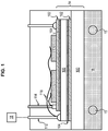
- the electronic module 14 comprises in one embodiment a base substrate 100 forming a support on which electronic components 110 are fixed, such as bipolar insulated gate transistors, diodes, capacitors, inductors, etc. As shown in figure 1 , these components 110 may require transmitters 112, doors 114, a collector 116 and connecting wires 118 for example.
- Different layers of material such as a brazed joint 102, a copper sole 104, another insulating substrate 106, for example ceramic, to make interconnections between the semiconductors and with external circuits on the copper sole 104 , are conventionally provided for the operation of the electronic module.
- the electronic module 14 includes a phase change material, referenced PCM for " Phase-change material ".
- PCM phase change material
- the figure 2 shows various embodiments detailed below.
- PCM materials change state, usually from solid to liquid, as soon as their melting temperature is reached.
- PCM materials which change phase from a solid or liquid state to a gaseous state, we speak more generally of phase change temperature Tf. This temperature Tf is a characteristic of the PCM material.
- the demand for electrical power from an electrical system can be very high over times which do not exceed a few tens of seconds or even a minute.
- the use of PCM materials allows better thermal management as close as possible to critical 110 electronic components such as static components, capacitors, inductors, etc. Indeed, reaching its melting temperature therefore by passing from the solid state to the liquid state, the PCM material will absorb a quantity of heat while remaining at the same temperature (by the time the entire material has changed state ) and a thermal transfer will then take place between the electronic components 110 inside the electronic module 14 and this PCM material.
- This absorption is linked to the enthalpy of change of state of the material PCM, also called latent heat, which corresponds to the energy which a unit of mass of the material must receive to change state.
- the PCM material will then absorb the temperature spike.
- one of the main problems in the development of electronics on board aircraft is that of the temperature resistance of the electronic components 110, in particular those which are soldered / or soldered to the substrate 100.
- the thermomechanical constraints between the component 110 and the substrate 100 can in certain cases cause delamination of the solder or the solder of the component on its substrate, which can destroy the component.
- Such uses of PCM material are already known, as in the document US 20130147050 .
- the PCM material also allows gains in sizing and occupied volume.
- the electronic components 110 such as the transistors, capacitors, inductors, can be dimensioned not on a maximum temperature peak but on an averaged lower temperature.
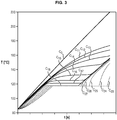
- the PCM material has a primary role, which is to absorb heat to prevent the electronic module 14 from exceeding a critical temperature.
- the figure 3 illustrates this absorption as a function of time: the curve C0 represents the temperature rise of the electronic module 14 in the absence of PCM material, the curves C11 to C18 represent the temperature rise of the electronic module 14 in the presence of PCM material for different thermal resistances between the PCM material and the substrate 100, the curves C23 to C27 represent the temperature rise of the PCM material (in connection with the curves C13 to C17). It is noted that the phase change temperature Tf of the PCM material is slightly less than 120 ° C.
- the electronic module 14 also has the function of heating the fuel.
- power peaks can generate too much heat and that the management of heat transfer is problematic. Consequently, the PCM material, which has absorbed the heat peak, gradually returns it to the exchanger 16a, 16b.
- the PCM material makes it possible to average the heat transfer between the electronic module 14 and the fuel. In this way, the risks of vaporization of said fuel are greatly reduced.
- PCM material in such a heat exchange architecture between the electronic module 14 and the fuel circuit 15 makes it possible to put a thermal barrier which, by diffusing the heat over time, protects the fuel from vaporization, while protecting module 14 from overheating.
- the PCM material is used here as a radiator, from the energy stored via the electronic module 14 .
- a PCM material is chosen whose phase change temperature Tf is lower than the vaporization temperature Tv of the fuel.
- a temperature Tf of less than 150 ° C, preferably 140 ° C, more preferably less than or equal to 130 ° C is suitable.
- the temperature Tf is greater than 120 ° C, to prevent the change of state from being completely performed while the electronic module 14 has not yet reached temperatures which could compromise its operation.
- PCM materials in the electronic module can be done in different ways, as shown on the figure 2 which schematize three variants, not necessarily mutually exclusive.
- the electronic components 110 are encapsulated in the PCM1 material.
- a specific matrix comprising PCM material is used. This variant requires that the electronic components 110 be waterproof.
- the PCM2 material can be integrated into the substrate 100.
- the document is known in particular US2013 / 0147050 which discloses such integration in the substrate 100.
- a specific volume must then be arranged in the substrate 100.
- a cold plate 120 is provided against the substrate 110, on the side opposite to the electronic components 110.
- the cold plate 120 is therefore positioned between the heat exchanger 16 and the base substrate 100.
- the cold plate 120 has the function of promoting the cooling of the electronic module 14.
- the PCM3 material is then integrated into this cold plate 120.
- the relative positioning of the fuel circuit and the base substrate and / or the cold plate can be adapted.
- the heat exchanger can be housed in the base substrate 100 or in the cold plate 120.
- the exchanger can then take the form of a fluid circuit, such as a branching of a pipe, arranged in the plate.
- the circulation of the fluid is then preferably forced by a dedicated pump.
- the PCM material can include hydrated salts, paraffins, and / or alcohols.
- PCM materials also lies in the gain in mass and volume compared to other technologies.
- the electronic module 14 is a power module, configured to convert the energy supplied by the energy source. It is therefore particularly subject to temperature rises, in particular during very short times during which it is stressed.
- the electronic components 110 can in particular be power semiconductors.
- the figure 4 illustrates an aircraft 1 with rotary wing, more specifically a helicopter with a main rotor 2 and an anti-torque tail rotor 3 coupled to a power unit 4 for their actuation.
- the engine group 4 illustrated comprises a first heat engine 5a and a second heat engine 5b.
- These heat engines 5a, 5b are turbine heat engines and more specifically turboshaft engines, the power take-off shafts 6 of which are both connected to a main gearbox 7 for actuating the main rotor 2 and the tail rotor 3.
- Each heat engine 5a, 5b comprises a compressor 8, a combustion chamber 9, a first turbine 10 connected by a rotary shaft 11 to the compressor 8 and a second turbine 12, or free turbine, coupled to the power take-off shaft 6
- the assembly of the compressor 8, combustion chamber 9, first turbine 10 and rotary shaft 11 is also known by the name of "gas generator”.
- the rotary shaft 11 of each gas generator is mechanically coupled to the energy source 13a, 13b, which is more specifically an electric machine 13a, 13b generally in the form of a motor generator, electrically connected to the electric module 14a , 14b, which is here an electronic power module, which is more specifically a power converter also electrically connected to an electrical storage device 20 and to an electrical network of the aircraft 1.
- This electrical storage device 20 can for example be a battery, although other electrical storage devices (eg fuel cells or flywheels) are also possible.
- the electric machines 13a, 13b are used both for starting the combustion engines 5a, 5b corresponding to and for generating electricity after this start.
- the electric machine 13a, 13b operates in engine mode, and the power electronics module 14a, 14b provides its electrical supply from the electrical network of the aircraft and / or from the electrical storage device 20.
- the electric machine 13a, 13b operates in generator mode, and the power electronics module 14a, 14b adapts the current generated to a voltage and amperage suitable for supplying the electrical network of the aircraft and / or of the electrical storage device 20.
- each electric machine 13a, 13b can also be used to maintain the corresponding heat engine 5a, 5b in standby mode, even during the flight of the aircraft 1, by rotating its rotary shaft 11, with the combustion 9 extinguished, at a reduced speed Nveille, which can be, for example, between 5 and 20% of a nominal speed N1 of the rotary shaft 11.
- Nveille which can be, for example, between 5 and 20% of a nominal speed N1 of the rotary shaft 11.
- the power supplied by the engine group 4 can vary significantly depending on the flight stage of the aircraft 1.
- the power required for the cruising speed is normally significantly less than the maximum continuous power of the engine group 4, and even less in relation to its maximum take-off power.
- the power unit 4 being dimensioned as a function of the latter, it is appreciably oversized with respect to the power required for the cruising speed. Consequently, when cruising, with the two heat engines 5a, 5b in operation, they could find themselves far from their optimal operating regime, which would result in a relatively high specific consumption.
- an engine group comprising a plurality of heat engines, it is possible to maintain the cruising speed with at least one of these heat engines off.
- the first heat engine 5a is therefore switched off during the cruising speed of the aircraft 1, while the second heat engine 5b supplies all the power to the main rotor 2 and to the tail rotor 3 through the main gearbox 7.
- the electrical machine 13b associated with the second heat engine 5b simultaneously supplies the electrical network of the aircraft 1 through its power electronics module 14b and the electrical machine 13a through its electronics 14a.
- the first heat engine 5a is maintained in standby mode by actuation of its rotary shaft 11 by the corresponding electric machine 13a , powered through its power electronics module 14a.
- each is associated with the fuel supply circuits 15a, 15b, with the heat exchanger 16a, 16b and, moreover, a fuel filter 17a, 17b located downstream of the heat exchanger 16a, 16b in the direction of flow of the fuel to the heat engine 5a, 5b.
- each heat exchanger 16a, 16b is adjacent to a base of the power electronics module 14a, 14b (for example a cold plate 21) corresponding, in a housing 22, which can be sealed and common to the power electronics module 14a, 14b and to the corresponding heat exchanger 16a, 16b, so that the fuel flowing through the heat exchanger 16a or 16b can be heated by heat generated by the operation of the power electronics module 14a, 14b, and simultaneously contribute to the cooling of the power electronics module 14a, 14b to allow it to operate in an optimal temperature range.
- a base of the power electronics module 14a, 14b for example a cold plate 21
- each electronics module of power 14a, 14b can treat a power Pe of the order of 100 kW, with heat losses of less than 10%, thus resulting in a caloric power Ph of, for example, less than 10 kW, or even less than 1 kW .
- each power electronics module 14a, 14b can have a normal operating mode and an operating mode with degraded electrical efficiency which can be implemented to generate additional heat for heating the fuel.
- This operating mode with degraded efficiency can be obtained for example by imposing on semiconductors of the power electronics module 14a, 14b a cutting frequency higher than that which would normally be applied according to the usual electrical dimensioning criteria.
- Each fuel supply circuit 15a, 15b may also include a bypass line 18a, 18b of the heat exchanger 16a, 16b, as well as a three-way valve 19a, 19b for controlling the flow of fuel through the 'heat exchanger 16a, 16b or by the bypass duct 18a, 18b.
- the latter To heat the fuel supplying one of the heat engines 5a, 5b during a start-up of the latter at low temperature before lighting the combustion chamber 9, the latter is directed through the corresponding heat exchanger 16a, 16b, in which it is heated by the heat generated by the operation of the power electronics module 14a, 14b through which the electric machine 13a, 13b is electrically powered to rotate the rotary shaft 11 of this heat engine 5a, 5b.
- the heat generated by the power electronics module 14a, 14b in normal operating mode is insufficient to allow a rapid start without risk of clogging of the fuel filter 17a, 17b by water ice particles, a mode of degraded electrical efficiency operation of the power electronics module 14a, 14b can be implemented to increase the generation of heat in this module, and its transmission, through the heat exchanger 16a, 16b, to the fuel.
- the three-way valve 19a, 19b can direct the fuel through the corresponding bypass pipe 18a, 18b.
Landscapes
- Engineering & Computer Science (AREA)
- Chemical & Material Sciences (AREA)
- Combustion & Propulsion (AREA)
- Mechanical Engineering (AREA)
- General Engineering & Computer Science (AREA)
- Aviation & Aerospace Engineering (AREA)
- Engine Equipment That Uses Special Cycles (AREA)
- Ceramic Engineering (AREA)
- Fuel Cell (AREA)
- Cooling Or The Like Of Semiconductors Or Solid State Devices (AREA)
- Control Of Temperature (AREA)
Claims (11)
- Gruppe, umfassend:einen Versorgungsschaltkreis für Kraftstoff (15, 15a, 15b), der zum Versorgen eines Verbrennungsmotors mit Turbine mit Kraftstoff ausgestaltet ist,ein elektronisches Modul (14, 14a, 14b),eine Energiequelle (13, 13a, 13b) zum Beliefern des elektronischen Moduls (14, 14a, 14b) mit elektrischer Energie,einen Wärmetauscher (16, 16a, 16b), der angeordnet ist, um einen Wärmestrom des elektronischen Moduls (14, 14a, 14b) zum Versorungsschaltkreis für Kraftstoff (15, 15a, 15b) zu ermöglichen,wobei die Gruppe dadurch gekennzeichnet ist, dass das elektronische Modul (14, 14a, 14b) ein Material mit Phasenänderung (PCM1, PCM2, PCM3) umfasst, das ausgestaltet ist, um den Zustand zu ändern, wenn seine Temperatur eine vorbestimmte Phasenänderungstemperatur (Tf) erreicht.
- Gruppe gemäß dem voranstehenden Anspruch, bei der die genannte vorbestimmte Phasenänderungstemperatur (Tf) niedriger ist als die Verdampfungstemperatur des Kraftstoffs (Tv).
- Gruppe gemäß irgendeinem der voranstehenden Ansprüche, bei der das elektronische Modul (14, 14a, 14b) ein elektronisches Leistungsmodul ist, das zum Umwandeln der von der Energiequelle (13, 13a, 13b) gelieferten Energie ausgestaltet ist.
- Gruppe gemäß irgendeinem der voranstehenden Ansprüche, bei der die Phasenänderungstemperatur (Tf) niedriger ist als 150° C, bevorzugt nieder als 140° C.
- Gruppe gemäß irgendeinem der voranstehenden Ansprüche, bei der das elektronische Modul (14, 14a, 14b) die folgenden Elemente umfasst:- ein Basissubstrat (100), das einen Träger bildet,- elektronische Bauteile (110), die auf dem Träger angeordnet sind,
und bei dem der Tauscher (16, 16a, 16b) in Bezug auf das Basissubstrat (100) auf der den Bauteilen (110) gegenüberliegenden Seite angeordnet ist, - Gruppe gemäß Anspruch 5, bei der die elektronischen Bauteile (110) in dem Material mit Phasenänderung (PCM1) verkapselt sind.
- Gruppe gemäß Anspruch 5 oder 6, bei der das Material mit Phasenänderung (PCM2) in das Basissubstrat (100) eingebaut ist.
- Gruppe gemäß Anspruch 5 oder 6 oder 7, bei der das elektronische Modul (14, 14a, 14b) eine kalte Platte (120) umfasst und bei der das Material mit Phasenänderung (PCM3) in die kalte Platte eingebaut ist.
- Motorsatz (4), umfassend:einen Verbrennungsmotor mit Turbine (5a, 5b),eine Gruppe gemäß irgendeinem der voranstehenden Ansprüche,bei der der Versorgungsschaltkreis mit Kraftstoff (15, 15a, 15b) zum Versorgen des Verbrennungsmotors (5a, 5b) ausgestaltet ist.
- Motorsatz (4) gemäß dem voranstehenden Anspruch, bei dem die Energiequelle eine elektrische Maschine (13, 13a, 13b) ist, die als Motor und als Generator funktionieren kann und bei dem die elektrische Maschine mechanisch an eine sich drehende Welle des Verbrennungsmotors gekoppelt ist.
- Erhitzungsverfahren von Kraftstoff mithilfe einer Gruppe gemäß irgendeinem der Ansprüche 1 bis 8 oder eines Motorsatzes gemäß irgendeinem der Ansprüche 9 bis 10, bei dem der Kraftstoff im Wärmetauscher (16, 16a, 16b) des Versorgungsschaltkreises mit Kraftstoff )15, 15a, 15b) durch die Wärme erhitzt wird, die vom elektronischen Modul (14) durch das Phasenänderungsmaterial (PCM1, PCM2, PCM3) abgegeben wird.
Priority Applications (1)
| Application Number | Priority Date | Filing Date | Title |
|---|---|---|---|
| PL17736986T PL3468874T3 (pl) | 2016-06-13 | 2017-06-12 | Integracja materiału zmiennofazowego dla ograniczenia temperatury paliwa z modułu elektronicznego |
Applications Claiming Priority (2)
| Application Number | Priority Date | Filing Date | Title |
|---|---|---|---|
| FR1655451A FR3052440B1 (fr) | 2016-06-13 | 2016-06-13 | Integration d'un materiau a changement de phase pour limiter la temperature du carburant a partir d'un module electronique. |
| PCT/FR2017/051506 WO2017216462A1 (fr) | 2016-06-13 | 2017-06-12 | Intégration d'un matériau à changement de phase pour limiter la température du carburant à partir d'un module électronique |
Publications (2)
| Publication Number | Publication Date |
|---|---|
| EP3468874A1 EP3468874A1 (de) | 2019-04-17 |
| EP3468874B1 true EP3468874B1 (de) | 2020-04-29 |
Family
ID=57485575
Family Applications (1)
| Application Number | Title | Priority Date | Filing Date |
|---|---|---|---|
| EP17736986.5A Active EP3468874B1 (de) | 2016-06-13 | 2017-06-12 | Integration eines speicherstoffes zur begrenzung der temperatur eines brennstoffes von einem elektronischen modul |
Country Status (10)
| Country | Link |
|---|---|
| US (1) | US11085376B2 (de) |
| EP (1) | EP3468874B1 (de) |
| JP (1) | JP6946423B2 (de) |
| KR (1) | KR102371526B1 (de) |
| CN (1) | CN109311539B (de) |
| CA (1) | CA3027116C (de) |
| FR (1) | FR3052440B1 (de) |
| PL (1) | PL3468874T3 (de) |
| RU (1) | RU2740107C2 (de) |
| WO (1) | WO2017216462A1 (de) |
Families Citing this family (11)
| Publication number | Priority date | Publication date | Assignee | Title |
|---|---|---|---|---|
| KR102191753B1 (ko) * | 2018-12-12 | 2020-12-16 | 한국철도기술연구원 | Pcm 내장형 히트싱크 |
| FR3097594B1 (fr) * | 2019-06-21 | 2023-05-12 | Safran Aircraft Engines | Rampe d’alimentation en carburant et chambre de combustion pour turbomachine |
| US20210207540A1 (en) * | 2020-01-02 | 2021-07-08 | United Technologies Corporation | Systems and methods for fuel cell auxiliary power in secondary fuel applications |
| US12139109B2 (en) | 2020-10-29 | 2024-11-12 | General Electric Company | Systems and methods of servicing equipment |
| US12511623B2 (en) | 2020-10-29 | 2025-12-30 | General Electric Company | Systems and methods of servicing equipment |
| US11992952B2 (en) * | 2020-10-29 | 2024-05-28 | General Electric Company | Systems and methods of servicing equipment |
| US12208925B2 (en) | 2020-10-29 | 2025-01-28 | General Electric Company | Systems and methods of servicing equipment |
| US11935290B2 (en) | 2020-10-29 | 2024-03-19 | Oliver Crispin Robotics Limited | Systems and methods of servicing equipment |
| US20220178306A1 (en) * | 2020-12-09 | 2022-06-09 | Pratt & Whitney Canada Corp. | Method of operating an aircraft engine and fuel system using multiple fuel types |
| GB202201313D0 (en) * | 2022-02-02 | 2022-03-16 | Rolls Royce Plc | Combination of a gas turbine engine and a power electronics |
| GB202201316D0 (en) | 2022-02-02 | 2022-03-16 | Rolls Royce Plc | Combination of a gas turbine engine and a power electronics |
Family Cites Families (14)
| Publication number | Priority date | Publication date | Assignee | Title |
|---|---|---|---|---|
| JPH01248551A (ja) * | 1988-03-30 | 1989-10-04 | Toshiba Corp | 半導体パッケージ |
| US5105875A (en) * | 1991-01-10 | 1992-04-21 | Sundstrand Corporation | Cooling system for auxiliary power unit |
| US6182435B1 (en) * | 1997-06-05 | 2001-02-06 | Hamilton Sundstrand Corporation | Thermal and energy management method and apparatus for an aircraft |
| US6400896B1 (en) * | 1999-07-02 | 2002-06-04 | Trexco, Llc | Phase change material heat exchanger with heat energy transfer elements extending through the phase change material |
| JP2001024126A (ja) * | 1999-07-09 | 2001-01-26 | Fuji Electric Co Ltd | 直膨式コールドプレート |
| US7222821B2 (en) * | 2001-11-21 | 2007-05-29 | Matos Jeffrey A | Method and apparatus for treating fuel to temporarily reduce its combustibility |
| CN101576132A (zh) * | 2009-06-05 | 2009-11-11 | 浙江万安科技股份有限公司 | 一种液体相变制动器 |
| US8726663B2 (en) * | 2010-01-05 | 2014-05-20 | General Electric Company | Combined cycle system employing phase change material |
| FR2967132B1 (fr) | 2010-11-04 | 2012-11-09 | Turbomeca | Procede d'optimisation de la consommation specifique d'un helicoptere bimoteur et architecture bimoteur dissymetrique a systeme de regulation pour sa mise en oeuvre |
| US8844293B2 (en) * | 2011-03-22 | 2014-09-30 | Pratt & Whitney Canada Corp. | Fuel system for gas turbine engine |
| US20130147050A1 (en) * | 2011-12-12 | 2013-06-13 | Advanced Cooling Technologies, Inc. | Semiconductor having integrally-formed enhanced thermal management |
| US9181876B2 (en) * | 2012-01-04 | 2015-11-10 | General Electric Company | Method and apparatus for operating a gas turbine engine |
| US9316152B2 (en) * | 2012-06-13 | 2016-04-19 | General Electric Company | Active control of bucket cooling supply for turbine |
| EP2938854A1 (de) * | 2012-12-28 | 2015-11-04 | General Electric Company | Turbinenmotoranordnung und zweistoff-flugzeugsystem |
-
2016
- 2016-06-13 FR FR1655451A patent/FR3052440B1/fr active Active
-
2017
- 2017-06-12 CA CA3027116A patent/CA3027116C/fr active Active
- 2017-06-12 EP EP17736986.5A patent/EP3468874B1/de active Active
- 2017-06-12 WO PCT/FR2017/051506 patent/WO2017216462A1/fr not_active Ceased
- 2017-06-12 KR KR1020197000668A patent/KR102371526B1/ko not_active Expired - Fee Related
- 2017-06-12 RU RU2019100090A patent/RU2740107C2/ru active
- 2017-06-12 PL PL17736986T patent/PL3468874T3/pl unknown
- 2017-06-12 CN CN201780036539.4A patent/CN109311539B/zh active Active
- 2017-06-12 JP JP2019517173A patent/JP6946423B2/ja not_active Expired - Fee Related
- 2017-06-12 US US16/309,137 patent/US11085376B2/en active Active
Non-Patent Citations (1)
| Title |
|---|
| None * |
Also Published As
| Publication number | Publication date |
|---|---|
| US20190309687A1 (en) | 2019-10-10 |
| PL3468874T3 (pl) | 2020-09-07 |
| FR3052440B1 (fr) | 2018-05-18 |
| CA3027116A1 (fr) | 2017-12-21 |
| RU2019100090A (ru) | 2020-07-14 |
| WO2017216462A1 (fr) | 2017-12-21 |
| FR3052440A1 (fr) | 2017-12-15 |
| JP2019527317A (ja) | 2019-09-26 |
| JP6946423B2 (ja) | 2021-10-06 |
| RU2740107C2 (ru) | 2021-01-11 |
| CN109311539A (zh) | 2019-02-05 |
| CN109311539B (zh) | 2022-02-11 |
| US11085376B2 (en) | 2021-08-10 |
| EP3468874A1 (de) | 2019-04-17 |
| CA3027116C (fr) | 2024-05-21 |
| RU2019100090A3 (de) | 2020-09-18 |
| KR20190017916A (ko) | 2019-02-20 |
| KR102371526B1 (ko) | 2022-03-07 |
Similar Documents
| Publication | Publication Date | Title |
|---|---|---|
| EP3468874B1 (de) | Integration eines speicherstoffes zur begrenzung der temperatur eines brennstoffes von einem elektronischen modul | |
| EP4158169B1 (de) | Anlage zum erwärmen eines kryogenen kraftstoffs | |
| EP3052771B1 (de) | Für den betrieb in einem drehgetriebemodus ausgelegte turbomaschine | |
| CA2678657C (fr) | Systeme de refroidissement et de regulation en temperature d'equipements d'un ensemble propulsif d'aeronef | |
| EP2427370B1 (de) | Rotor eines propfan-triebwerks mit elektrischem generator | |
| FR2503256A1 (fr) | Equilibrage de flux thermique entre des elements associes a une turbine a gaz | |
| EP4305287B1 (de) | Brennstoffkonditionierungssystem und verfahren zur versorgung eines flugzeugturbinenmotors mit brennstoff aus einem kryotank | |
| WO2023072614A1 (fr) | Système de conditionnement de carburant pour alimenter une turbomachine d'aéronef, aéronef et procédé d'utilisation | |
| FR3138412A1 (fr) | Ensemble propulsif amélioré pour aéronef hybridé multi moteurs | |
| FR2925110A1 (fr) | Dispositif d'alimentation en huile d'un moteur d'aeronef equipe d'au moins un demarreur-generateur. | |
| WO2025012539A1 (fr) | Ensemble propulsif d'aeronef et procede de gestion thermique | |
| EP3947937A1 (de) | Kühlsystem für ein flugtriebwerk | |
| WO2023152232A1 (fr) | Turbomachine de chauffage pour un système de conditionnement de carburant configuré pour alimenter un turbomoteur d'aéronef à partir de carburant issu d'un réservoir cryogénique | |
| FR3138411A1 (fr) | Ensemble propulsif amélioré pour aéronef hybridé multi moteurs | |
| FR3069738A1 (fr) | Turbomachine a moteur de demarrage a ventilation reversible, procede de refroidissement associe | |
| FR3032233A1 (fr) | Groupe moteur et procede de rechauffement de carburant | |
| FR3017491A1 (fr) | Groupe de generation electrique et procede de demarrage |
Legal Events
| Date | Code | Title | Description |
|---|---|---|---|
| STAA | Information on the status of an ep patent application or granted ep patent |
Free format text: STATUS: UNKNOWN |
|
| STAA | Information on the status of an ep patent application or granted ep patent |
Free format text: STATUS: THE INTERNATIONAL PUBLICATION HAS BEEN MADE |
|
| PUAI | Public reference made under article 153(3) epc to a published international application that has entered the european phase |
Free format text: ORIGINAL CODE: 0009012 |
|
| STAA | Information on the status of an ep patent application or granted ep patent |
Free format text: STATUS: REQUEST FOR EXAMINATION WAS MADE |
|
| 17P | Request for examination filed |
Effective date: 20190111 |
|
| AK | Designated contracting states |
Kind code of ref document: A1 Designated state(s): AL AT BE BG CH CY CZ DE DK EE ES FI FR GB GR HR HU IE IS IT LI LT LU LV MC MK MT NL NO PL PT RO RS SE SI SK SM TR |
|
| AX | Request for extension of the european patent |
Extension state: BA ME |
|
| DAV | Request for validation of the european patent (deleted) | ||
| DAX | Request for extension of the european patent (deleted) | ||
| GRAP | Despatch of communication of intention to grant a patent |
Free format text: ORIGINAL CODE: EPIDOSNIGR1 |
|
| STAA | Information on the status of an ep patent application or granted ep patent |
Free format text: STATUS: GRANT OF PATENT IS INTENDED |
|
| INTG | Intention to grant announced |
Effective date: 20191213 |
|
| GRAS | Grant fee paid |
Free format text: ORIGINAL CODE: EPIDOSNIGR3 |
|
| GRAA | (expected) grant |
Free format text: ORIGINAL CODE: 0009210 |
|
| STAA | Information on the status of an ep patent application or granted ep patent |
Free format text: STATUS: THE PATENT HAS BEEN GRANTED |
|
| AK | Designated contracting states |
Kind code of ref document: B1 Designated state(s): AL AT BE BG CH CY CZ DE DK EE ES FI FR GB GR HR HU IE IS IT LI LT LU LV MC MK MT NL NO PL PT RO RS SE SI SK SM TR |
|
| REG | Reference to a national code |
Ref country code: GB Ref legal event code: FG4D Free format text: NOT ENGLISH |
|
| REG | Reference to a national code |
Ref country code: CH Ref legal event code: EP |
|
| REG | Reference to a national code |
Ref country code: AT Ref legal event code: REF Ref document number: 1262956 Country of ref document: AT Kind code of ref document: T Effective date: 20200515 |
|
| REG | Reference to a national code |
Ref country code: DE Ref legal event code: R096 Ref document number: 602017015770 Country of ref document: DE |
|
| REG | Reference to a national code |
Ref country code: IE Ref legal event code: FG4D Free format text: LANGUAGE OF EP DOCUMENT: FRENCH |
|
| REG | Reference to a national code |
Ref country code: NL Ref legal event code: MP Effective date: 20200429 |
|
| REG | Reference to a national code |
Ref country code: LT Ref legal event code: MG4D |
|
| PG25 | Lapsed in a contracting state [announced via postgrant information from national office to epo] |
Ref country code: GR Free format text: LAPSE BECAUSE OF FAILURE TO SUBMIT A TRANSLATION OF THE DESCRIPTION OR TO PAY THE FEE WITHIN THE PRESCRIBED TIME-LIMIT Effective date: 20200730 Ref country code: IS Free format text: LAPSE BECAUSE OF FAILURE TO SUBMIT A TRANSLATION OF THE DESCRIPTION OR TO PAY THE FEE WITHIN THE PRESCRIBED TIME-LIMIT Effective date: 20200829 Ref country code: SE Free format text: LAPSE BECAUSE OF FAILURE TO SUBMIT A TRANSLATION OF THE DESCRIPTION OR TO PAY THE FEE WITHIN THE PRESCRIBED TIME-LIMIT Effective date: 20200429 Ref country code: PT Free format text: LAPSE BECAUSE OF FAILURE TO SUBMIT A TRANSLATION OF THE DESCRIPTION OR TO PAY THE FEE WITHIN THE PRESCRIBED TIME-LIMIT Effective date: 20200831 Ref country code: FI Free format text: LAPSE BECAUSE OF FAILURE TO SUBMIT A TRANSLATION OF THE DESCRIPTION OR TO PAY THE FEE WITHIN THE PRESCRIBED TIME-LIMIT Effective date: 20200429 Ref country code: NO Free format text: LAPSE BECAUSE OF FAILURE TO SUBMIT A TRANSLATION OF THE DESCRIPTION OR TO PAY THE FEE WITHIN THE PRESCRIBED TIME-LIMIT Effective date: 20200729 Ref country code: LT Free format text: LAPSE BECAUSE OF FAILURE TO SUBMIT A TRANSLATION OF THE DESCRIPTION OR TO PAY THE FEE WITHIN THE PRESCRIBED TIME-LIMIT Effective date: 20200429 |
|
| REG | Reference to a national code |
Ref country code: AT Ref legal event code: MK05 Ref document number: 1262956 Country of ref document: AT Kind code of ref document: T Effective date: 20200429 |
|
| PG25 | Lapsed in a contracting state [announced via postgrant information from national office to epo] |
Ref country code: LV Free format text: LAPSE BECAUSE OF FAILURE TO SUBMIT A TRANSLATION OF THE DESCRIPTION OR TO PAY THE FEE WITHIN THE PRESCRIBED TIME-LIMIT Effective date: 20200429 Ref country code: BG Free format text: LAPSE BECAUSE OF FAILURE TO SUBMIT A TRANSLATION OF THE DESCRIPTION OR TO PAY THE FEE WITHIN THE PRESCRIBED TIME-LIMIT Effective date: 20200729 Ref country code: RS Free format text: LAPSE BECAUSE OF FAILURE TO SUBMIT A TRANSLATION OF THE DESCRIPTION OR TO PAY THE FEE WITHIN THE PRESCRIBED TIME-LIMIT Effective date: 20200429 Ref country code: HR Free format text: LAPSE BECAUSE OF FAILURE TO SUBMIT A TRANSLATION OF THE DESCRIPTION OR TO PAY THE FEE WITHIN THE PRESCRIBED TIME-LIMIT Effective date: 20200429 |
|
| PG25 | Lapsed in a contracting state [announced via postgrant information from national office to epo] |
Ref country code: NL Free format text: LAPSE BECAUSE OF FAILURE TO SUBMIT A TRANSLATION OF THE DESCRIPTION OR TO PAY THE FEE WITHIN THE PRESCRIBED TIME-LIMIT Effective date: 20200429 Ref country code: AL Free format text: LAPSE BECAUSE OF FAILURE TO SUBMIT A TRANSLATION OF THE DESCRIPTION OR TO PAY THE FEE WITHIN THE PRESCRIBED TIME-LIMIT Effective date: 20200429 |
|
| PG25 | Lapsed in a contracting state [announced via postgrant information from national office to epo] |
Ref country code: SM Free format text: LAPSE BECAUSE OF FAILURE TO SUBMIT A TRANSLATION OF THE DESCRIPTION OR TO PAY THE FEE WITHIN THE PRESCRIBED TIME-LIMIT Effective date: 20200429 Ref country code: EE Free format text: LAPSE BECAUSE OF FAILURE TO SUBMIT A TRANSLATION OF THE DESCRIPTION OR TO PAY THE FEE WITHIN THE PRESCRIBED TIME-LIMIT Effective date: 20200429 Ref country code: DK Free format text: LAPSE BECAUSE OF FAILURE TO SUBMIT A TRANSLATION OF THE DESCRIPTION OR TO PAY THE FEE WITHIN THE PRESCRIBED TIME-LIMIT Effective date: 20200429 Ref country code: AT Free format text: LAPSE BECAUSE OF FAILURE TO SUBMIT A TRANSLATION OF THE DESCRIPTION OR TO PAY THE FEE WITHIN THE PRESCRIBED TIME-LIMIT Effective date: 20200429 Ref country code: MC Free format text: LAPSE BECAUSE OF FAILURE TO SUBMIT A TRANSLATION OF THE DESCRIPTION OR TO PAY THE FEE WITHIN THE PRESCRIBED TIME-LIMIT Effective date: 20200429 Ref country code: RO Free format text: LAPSE BECAUSE OF FAILURE TO SUBMIT A TRANSLATION OF THE DESCRIPTION OR TO PAY THE FEE WITHIN THE PRESCRIBED TIME-LIMIT Effective date: 20200429 Ref country code: ES Free format text: LAPSE BECAUSE OF FAILURE TO SUBMIT A TRANSLATION OF THE DESCRIPTION OR TO PAY THE FEE WITHIN THE PRESCRIBED TIME-LIMIT Effective date: 20200429 |
|
| REG | Reference to a national code |
Ref country code: CH Ref legal event code: PL |
|
| REG | Reference to a national code |
Ref country code: DE Ref legal event code: R097 Ref document number: 602017015770 Country of ref document: DE |
|
| PG25 | Lapsed in a contracting state [announced via postgrant information from national office to epo] |
Ref country code: SK Free format text: LAPSE BECAUSE OF FAILURE TO SUBMIT A TRANSLATION OF THE DESCRIPTION OR TO PAY THE FEE WITHIN THE PRESCRIBED TIME-LIMIT Effective date: 20200429 |
|
| PLBE | No opposition filed within time limit |
Free format text: ORIGINAL CODE: 0009261 |
|
| STAA | Information on the status of an ep patent application or granted ep patent |
Free format text: STATUS: NO OPPOSITION FILED WITHIN TIME LIMIT |
|
| PG25 | Lapsed in a contracting state [announced via postgrant information from national office to epo] |
Ref country code: LU Free format text: LAPSE BECAUSE OF NON-PAYMENT OF DUE FEES Effective date: 20200612 |
|
| 26N | No opposition filed |
Effective date: 20210201 |
|
| REG | Reference to a national code |
Ref country code: BE Ref legal event code: MM Effective date: 20200630 |
|
| PG25 | Lapsed in a contracting state [announced via postgrant information from national office to epo] |
Ref country code: CH Free format text: LAPSE BECAUSE OF NON-PAYMENT OF DUE FEES Effective date: 20200630 Ref country code: LI Free format text: LAPSE BECAUSE OF NON-PAYMENT OF DUE FEES Effective date: 20200630 Ref country code: IE Free format text: LAPSE BECAUSE OF NON-PAYMENT OF DUE FEES Effective date: 20200612 |
|
| PG25 | Lapsed in a contracting state [announced via postgrant information from national office to epo] |
Ref country code: SI Free format text: LAPSE BECAUSE OF FAILURE TO SUBMIT A TRANSLATION OF THE DESCRIPTION OR TO PAY THE FEE WITHIN THE PRESCRIBED TIME-LIMIT Effective date: 20200429 Ref country code: BE Free format text: LAPSE BECAUSE OF NON-PAYMENT OF DUE FEES Effective date: 20200630 |
|
| PG25 | Lapsed in a contracting state [announced via postgrant information from national office to epo] |
Ref country code: TR Free format text: LAPSE BECAUSE OF FAILURE TO SUBMIT A TRANSLATION OF THE DESCRIPTION OR TO PAY THE FEE WITHIN THE PRESCRIBED TIME-LIMIT Effective date: 20200429 Ref country code: MT Free format text: LAPSE BECAUSE OF FAILURE TO SUBMIT A TRANSLATION OF THE DESCRIPTION OR TO PAY THE FEE WITHIN THE PRESCRIBED TIME-LIMIT Effective date: 20200429 Ref country code: CY Free format text: LAPSE BECAUSE OF FAILURE TO SUBMIT A TRANSLATION OF THE DESCRIPTION OR TO PAY THE FEE WITHIN THE PRESCRIBED TIME-LIMIT Effective date: 20200429 |
|
| PG25 | Lapsed in a contracting state [announced via postgrant information from national office to epo] |
Ref country code: MK Free format text: LAPSE BECAUSE OF FAILURE TO SUBMIT A TRANSLATION OF THE DESCRIPTION OR TO PAY THE FEE WITHIN THE PRESCRIBED TIME-LIMIT Effective date: 20200429 |
|
| PGFP | Annual fee paid to national office [announced via postgrant information from national office to epo] |
Ref country code: PL Payment date: 20250604 Year of fee payment: 9 Ref country code: DE Payment date: 20250618 Year of fee payment: 9 |
|
| PGFP | Annual fee paid to national office [announced via postgrant information from national office to epo] |
Ref country code: GB Payment date: 20250625 Year of fee payment: 9 |
|
| PGFP | Annual fee paid to national office [announced via postgrant information from national office to epo] |
Ref country code: FR Payment date: 20250623 Year of fee payment: 9 |
|
| PGFP | Annual fee paid to national office [announced via postgrant information from national office to epo] |
Ref country code: CZ Payment date: 20250530 Year of fee payment: 9 |
|
| PGFP | Annual fee paid to national office [announced via postgrant information from national office to epo] |
Ref country code: IT Payment date: 20250630 Year of fee payment: 9 |