EP3468453B1 - Systems and methods for automated coronary plaque characterization and risk assessment using intravascular optical coherence tomography - Google Patents
Systems and methods for automated coronary plaque characterization and risk assessment using intravascular optical coherence tomography Download PDFInfo
- Publication number
- EP3468453B1 EP3468453B1 EP17811024.3A EP17811024A EP3468453B1 EP 3468453 B1 EP3468453 B1 EP 3468453B1 EP 17811024 A EP17811024 A EP 17811024A EP 3468453 B1 EP3468453 B1 EP 3468453B1
- Authority
- EP
- European Patent Office
- Prior art keywords
- plaque
- tissue
- features
- image
- neural network
- Prior art date
- Legal status (The legal status is an assumption and is not a legal conclusion. Google has not performed a legal analysis and makes no representation as to the accuracy of the status listed.)
- Active
Links
Images


Classifications
-
- A—HUMAN NECESSITIES
- A61—MEDICAL OR VETERINARY SCIENCE; HYGIENE
- A61B—DIAGNOSIS; SURGERY; IDENTIFICATION
- A61B5/00—Measuring for diagnostic purposes; Identification of persons
- A61B5/0059—Measuring for diagnostic purposes; Identification of persons using light, e.g. diagnosis by transillumination, diascopy, fluorescence
- A61B5/0082—Measuring for diagnostic purposes; Identification of persons using light, e.g. diagnosis by transillumination, diascopy, fluorescence adapted for particular medical purposes
- A61B5/0084—Measuring for diagnostic purposes; Identification of persons using light, e.g. diagnosis by transillumination, diascopy, fluorescence adapted for particular medical purposes for introduction into the body, e.g. by catheters
-
- A—HUMAN NECESSITIES
- A61—MEDICAL OR VETERINARY SCIENCE; HYGIENE
- A61B—DIAGNOSIS; SURGERY; IDENTIFICATION
- A61B5/00—Measuring for diagnostic purposes; Identification of persons
- A61B5/72—Signal processing specially adapted for physiological signals or for diagnostic purposes
- A61B5/7235—Details of waveform analysis
- A61B5/7264—Classification of physiological signals or data, e.g. using neural networks, statistical classifiers, expert systems or fuzzy systems
-
- A—HUMAN NECESSITIES
- A61—MEDICAL OR VETERINARY SCIENCE; HYGIENE
- A61B—DIAGNOSIS; SURGERY; IDENTIFICATION
- A61B5/00—Measuring for diagnostic purposes; Identification of persons
- A61B5/0059—Measuring for diagnostic purposes; Identification of persons using light, e.g. diagnosis by transillumination, diascopy, fluorescence
- A61B5/0062—Arrangements for scanning
- A61B5/0066—Optical coherence imaging
-
- A—HUMAN NECESSITIES
- A61—MEDICAL OR VETERINARY SCIENCE; HYGIENE
- A61B—DIAGNOSIS; SURGERY; IDENTIFICATION
- A61B5/00—Measuring for diagnostic purposes; Identification of persons
- A61B5/02—Detecting, measuring or recording for evaluating the cardiovascular system, e.g. pulse, heart rate, blood pressure or blood flow
- A61B5/02007—Evaluating blood vessel condition, e.g. elasticity, compliance
-
- A—HUMAN NECESSITIES
- A61—MEDICAL OR VETERINARY SCIENCE; HYGIENE
- A61B—DIAGNOSIS; SURGERY; IDENTIFICATION
- A61B6/00—Apparatus or devices for radiation diagnosis; Apparatus or devices for radiation diagnosis combined with radiation therapy equipment
- A61B6/02—Arrangements for diagnosis sequentially in different planes; Stereoscopic radiation diagnosis
- A61B6/03—Computed tomography [CT]
-
- G—PHYSICS
- G06—COMPUTING OR CALCULATING; COUNTING
- G06F—ELECTRIC DIGITAL DATA PROCESSING
- G06F18/00—Pattern recognition
-
- G—PHYSICS
- G06—COMPUTING OR CALCULATING; COUNTING
- G06T—IMAGE DATA PROCESSING OR GENERATION, IN GENERAL
- G06T7/00—Image analysis
- G06T7/0002—Inspection of images, e.g. flaw detection
- G06T7/0012—Biomedical image inspection
- G06T7/0014—Biomedical image inspection using an image reference approach
-
- G—PHYSICS
- G06—COMPUTING OR CALCULATING; COUNTING
- G06T—IMAGE DATA PROCESSING OR GENERATION, IN GENERAL
- G06T7/00—Image analysis
- G06T7/40—Analysis of texture
- G06T7/41—Analysis of texture based on statistical description of texture
- G06T7/45—Analysis of texture based on statistical description of texture using co-occurrence matrix computation
-
- A—HUMAN NECESSITIES
- A61—MEDICAL OR VETERINARY SCIENCE; HYGIENE
- A61B—DIAGNOSIS; SURGERY; IDENTIFICATION
- A61B5/00—Measuring for diagnostic purposes; Identification of persons
- A61B5/72—Signal processing specially adapted for physiological signals or for diagnostic purposes
- A61B5/7235—Details of waveform analysis
- A61B5/7264—Classification of physiological signals or data, e.g. using neural networks, statistical classifiers, expert systems or fuzzy systems
- A61B5/7267—Classification of physiological signals or data, e.g. using neural networks, statistical classifiers, expert systems or fuzzy systems involving training the classification device
-
- G—PHYSICS
- G06—COMPUTING OR CALCULATING; COUNTING
- G06T—IMAGE DATA PROCESSING OR GENERATION, IN GENERAL
- G06T2207/00—Indexing scheme for image analysis or image enhancement
- G06T2207/10—Image acquisition modality
- G06T2207/10072—Tomographic images
- G06T2207/10101—Optical tomography; Optical coherence tomography [OCT]
-
- G—PHYSICS
- G06—COMPUTING OR CALCULATING; COUNTING
- G06T—IMAGE DATA PROCESSING OR GENERATION, IN GENERAL
- G06T2207/00—Indexing scheme for image analysis or image enhancement
- G06T2207/20—Special algorithmic details
- G06T2207/20076—Probabilistic image processing
-
- G—PHYSICS
- G06—COMPUTING OR CALCULATING; COUNTING
- G06T—IMAGE DATA PROCESSING OR GENERATION, IN GENERAL
- G06T2207/00—Indexing scheme for image analysis or image enhancement
- G06T2207/20—Special algorithmic details
- G06T2207/20081—Training; Learning
-
- G—PHYSICS
- G06—COMPUTING OR CALCULATING; COUNTING
- G06T—IMAGE DATA PROCESSING OR GENERATION, IN GENERAL
- G06T2207/00—Indexing scheme for image analysis or image enhancement
- G06T2207/20—Special algorithmic details
- G06T2207/20084—Artificial neural networks [ANN]
-
- G—PHYSICS
- G06—COMPUTING OR CALCULATING; COUNTING
- G06T—IMAGE DATA PROCESSING OR GENERATION, IN GENERAL
- G06T2207/00—Indexing scheme for image analysis or image enhancement
- G06T2207/30—Subject of image; Context of image processing
- G06T2207/30004—Biomedical image processing
- G06T2207/30101—Blood vessel; Artery; Vein; Vascular
-
- G—PHYSICS
- G16—INFORMATION AND COMMUNICATION TECHNOLOGY [ICT] SPECIALLY ADAPTED FOR SPECIFIC APPLICATION FIELDS
- G16H—HEALTHCARE INFORMATICS, i.e. INFORMATION AND COMMUNICATION TECHNOLOGY [ICT] SPECIALLY ADAPTED FOR THE HANDLING OR PROCESSING OF MEDICAL OR HEALTHCARE DATA
- G16H50/00—ICT specially adapted for medical diagnosis, medical simulation or medical data mining; ICT specially adapted for detecting, monitoring or modelling epidemics or pandemics
- G16H50/20—ICT specially adapted for medical diagnosis, medical simulation or medical data mining; ICT specially adapted for detecting, monitoring or modelling epidemics or pandemics for computer-aided diagnosis, e.g. based on medical expert systems
Definitions
- Atherosclerosis and plaque rupture leading to myocardial infarction remain the leading cause of death worldwide [1].
- Inflammation and underlying cellular and molecular mechanisms [2-4] contribute to atherogenesis from initiation through progression, plaque rupture and ultimately, thrombosis.
- the vulnerable plaque recently defined by Virmani [5] as "thin-cap fibroatheroma”, results from inflammation and is characterized as having a thin fibrous cap typically less than 65 ⁇ m thick, increased infiltration of macrophages with decreased smooth muscle cells, and an increased lipid core size compared to stable plaques [6-8].
- Intravascular OCT is a recently developed catheter-based method for high-resolution intravascular imaging.
- IVOCT is the only approach that provides sufficient spatial resolution to image thin-cap fibroatheromas.
- TPL microscopy uses nonlinear optical properties of tissue and has been utilized to image plaque components such as endothelial cells, smooth muscle cells [16], elastin fibers [17,18], oxidized LDL [19] and lipid droplets [20] based on their endogenous autofluorescence. More recently, it has been reported that macrophages loaded with nanoparticles can be detected by TPL microscopy [21,22]. Fiber-based OCT [23,24] and TPL microscopy [25-28] has been reported respectively using photonic crystal fibers to transmit broadband light for achieving higher spatial resolution or to transmit ultrashort pulses for system size minimization. However, a combined fiber-based OCT-TPL system has not been previously realized.
- Coronary atherosclerotic plaque is generally composed of lipid rich, fibrous, or calcified tissues. Calcified plaques are linked to stable lesions, while lesions with high amounts of fibrous and/or lipid tissue are linked to unstable thin-capped fibroatheroma (TCFA) lesions. TCFAs are particularly risky, being responsible for the majority of acute coronary events, such as plaque ruptures (Fujii et al, 2015). Plaque tissue characterization can also help guide stent placement.
- plaque composition can be particularly predictive of disease and interventional outcome.
- quantitative characterization of plaque morphologies can advance the understanding of atherosclerosis mechanisms, uncover new diagnostic criteria, and hasten development and testing of new therapies.
- IVUS intravascular ultrasound
- CT computed tomography
- Intravascular optical coherence tomography typically has a 10 ⁇ m axial resolution, allowing for the detection of a larger range of plaque sizes.
- IVOCT uses broadband interferometry from a catheter-mounted light source to generate images based on the refractive indices and reflectivity of sample material.
- backscattered light from the arterial wall is interfered with light at a controlled path length to generate images at various tissue depths of up to 2 mm, making it ideally suited to radially imaging arteries.
- IVOCT can deliver this micron-level resolution in real-time, making it a great tool for noninvasive catheter-based intravascular imaging, in vivo.
- the existing plaque classification techniques include many shortcomings, and improved systems and methods are desired.
- the invention is defined by the system of claim 1 and the method of claim 8.
- Exemplary embodiments of the present disclosure include an automated algorithmic method to classify the plaque tissue present in the coronary artery that is based on IVOCT images co-registered with histology for validation.
- the described powerful algorithmic method for a tissue classification system based on histology, the clinical gold standard, as its ground truth can bridge the gap between the potential of IVOCT and clinical acceptance.
- Exemplary embodiments of the present disclosure include systems and methods for an automated coronary plaque characterization and risk assessment using intravascular optical coherence tomography and a smart-algorithm. Particular embodiments may incorporate optical coherence tomography systems and methods as disclosed in U.S. Patent Publications 2014/0268168 and 2016/0078309 .
- Exemplary embodiments include a system comprising: an imaging device comprising an optical coherence tomography light source, wherein the imaging device is configured to obtain an image of intravascular tissue comprising plaque; and a non-transitory computer readable medium configured to: analyze a pixel of the image with a first neural network configured to classify the plaque as a first tissue type of a plurality of tissue types; analyze the pixel of the image with a second neural network configured to classify the plaque as a second tissue type of the plurality of tissue types; and analyze the pixel of the image with a third neural network configured to classify the plaque as a third tissue type of the plurality of tissue types.
- histological data from the plurality of tissue types is analyzed to characterize tissue types of pixels selected to train the first, second and third neural networks.
- the first tissue type is lipid plaque
- the second tissue type is a calcific plaque
- the third tissue type is a fibrous plaque.
- the non-transitory computer readable medium is configured to optimize the first, second and third neural networks by evaluating a plurality of features of the image with nodes of the first, second and third neural networks to calculate sensitivity and specificity of the plurality of features using a receiver operating characteristic (ROC) curve.
- the plurality of features comprise one or more of the following Gray Level Co-Occurrence Matrix (GLCM) features: contrast, energy, correlation, homogeneity, entropy, and maximum probability.
- GLCM Gray Level Co-Occurrence Matrix
- the plurality of features comprise one or more of the following two-dimensional image statistics: mean value, variance, skewness, kurtosis, and energy.
- the optical coherence tomography light source is configured as a swept source optical coherence tomography light source.
- the optical coherence tomography light source is configured as a broadband optical coherence tomography light source.
- the imaging device further comprises a short pulsed excitation light source.
- the short pulsed excitation light source is a two photon luminescence light source.
- the imaging device further comprises a photonic crystal fiber configured to simultaneously: enable single-mode propagation of a first wavelength from the optical coherence tomography light source to a sample site; enable single-mode propagation of a second wavelength from the short-pulsed light source to the sample site; transmit an optical coherence tomography signal from the sample site, wherein the optical coherence tomography signal is generated from the first wavelength; and transmit an emission signal from the sample site, wherein the emission signal is induced by the second wavelength from the short-pulsed light source.
- a photonic crystal fiber configured to simultaneously: enable single-mode propagation of a first wavelength from the optical coherence tomography light source to a sample site; enable single-mode propagation of a second wavelength from the short-pulsed light source to the sample site; transmit an optical coherence tomography signal from the sample site, wherein the optical coherence tomography signal is generated from the first wavelength; and transmit an emission signal from the sample site, wherein the emission signal is induced by the second wavelength from the short
- Specific embodiments further comprise a first dichroic element, and in some embodiments, the first dichroic element is configured to direct the first and second wavelengths to the sample path.
- Certain embodiments comprise a second dichroic element, and in particular embodiments, the second dichroic element is configured to direct two photon luminescence toward a photon counting detector.
- Specific embodiments comprise a balanced detector, and in certain embodiments, the balanced detector is configured to minimize a non-interfering OCT component.
- Particular embodiments comprise a photon counting detector, and in some embodiments the photon counting detector is a photomultiplier tube or an avalanche photo diode. In certain embodiments, the photon counting detector is configured to detect two-photon luminescence.
- Particular embodiments include a method of characterizing coronary plaque, the method comprising: obtaining an image of a sample site using an optical coherence tomography light source emitting light from an optical fiber, wherein the image comprises intravascular tissue comprising plaque; analyzing quantitative data of a pixel of the image with a first neural network configured to classify the plaque as a first tissue type of a plurality of tissue types, wherein the first neural network comprises a first plurality of nodes and reads a first plurality of features; analyzing quantitative data of the pixel of the image with a second neural network configured to classify the plaque as a second tissue type of the plurality of tissue types, wherein the second neural network comprises a second plurality of nodes and reads a second plurality of features; and analyzing quantitative data of the pixel of the image with a third neural network configured to classify the plaque as a third tissue type of the plurality of tissue types, wherein the third neural network comprises a third plurality of nodes and reads a third plurality of features.
- histological data from the plurality of tissue types is analyzed to characterize tissue types of pixels selected to train the first, second and third neural networks.
- the first tissue type is lipid plaque
- the second tissue type is a calcific plaque
- the third tissue type is a fibrous plaque.
- the quantitative data includes classifying features comprising one or more of the following: contrast, energy, correlation, homogeneity, entropy, and maximum probability.
- the quantitative data includes classifying features comprising one or more of the following: mean value, variance, skewness, kurtosis, and energy. Specific embodiments include optimizing the first, second and third neural networks by calculating a receiver operating characteristic (ROC) curve which plots a true positive versus a false positive rate for a plurality of classifying features of the image.
- ROC receiver operating characteristic
- Some embodiments further comprise calculating an area under each receiver operating characteristic (ROC) curve for each of the plurality of classifying features.
- ROC receiver operating characteristic
- Certain embodiments further comprise ranking the plurality of classifying features by the area under each receiver operating characteristic (ROC) curve for each of the plurality of classifying features.
- Particular embodiments further comprise calculating a sensitivity and a specificity of the classifying features for the first, second and third neural networks.
- the sensitivity is a proportion of known plaque type data points that are correctly classified by each of the first, second and third neural networks.
- the specificity is a ratio of correct classifications to total classifications for a certain category of plaque tissue types for each of the first, second and third neural networks.
- each of the first, second and third neural networks is optimized by selecting a combination of nodes and classifying features for each of the first, second and third neural networks that result in the highest value of a sum of the specificity and sensitivity.
- Particular embodiments include a system comprising: an imaging device comprising an optical coherence tomography light source, wherein the imaging device is configured to obtain an image of intravascular tissue; and a non-transitory computer readable medium configured to analyze a pixel of the image with a first neural network configured to classify the intravascular tissue in the image as a first tissue type of a plurality of tissue types.
- a non-transitory computer readable medium configured to perform certain steps may do so via a computer processor or other hardware configured to read the non-transitory computer readable medium.
- histological data from a plurality of tissue types is analyzed to characterize tissue types of pixels selected to train the first neural network.
- the non-transitory computer readable medium is configured to analyze the pixel of the image with a second neural network configured to classify the intravascular tissue in the image as a second tissue type of the plurality of tissue types. In some embodiments, the non-transitory computer readable medium is configured to analyze the pixel of the image with a third neural network configured to classify the intravascular tissue in the image as a third tissue type of the plurality of tissue types.
- histological data from the plurality of tissue types is analyzed to characterize tissue types of pixels selected to train the first, second and third neural networks.
- the first tissue type is lipid plaque
- the second tissue type is a calcific plaque
- the third tissue type is a fibrous plaque.
- the non-transitory computer readable medium is configured to optimize the first, second and third neural networks by evaluating a plurality of features of the image with nodes of the first, second and third neural networks to calculate sensitivity and specificity of the plurality of features using a receiver operating characteristic (ROC) curve.
- ROC receiver operating characteristic
- the plurality of features comprise one or more of the following Gray Level Co-Occurrence Matrix (GLCM) features: contrast, energy, correlation, homogeneity, entropy, and maximum probability.
- GLCM Gray Level Co-Occurrence Matrix
- the plurality of features comprise one or more of the following two-dimensional image statistics: mean value, variance, skewness, kurtosis, and energy.
- the optical coherence tomography light source is configured as a swept source optical coherence tomography light source. In some embodiments, the optical coherence tomography light source is configured as a broadband optical coherence tomography light source.
- the imaging device further comprises a short pulsed excitation light source. In certain embodiments, the short pulsed excitation light source is a two photon luminescence light source.
- the imaging device further comprises a photonic crystal fiber configured to simultaneously: enable single-mode propagation of a first wavelength from the optical coherence tomography light source to a sample site; enable single-mode propagation of a second wavelength from the short-pulsed light source to the sample site; transmit an optical coherence tomography signal from the sample site, wherein the optical coherence tomography signal is generated from the first wavelength; and transmit an emission signal from the sample site, wherein the emission signal is induced by the second wavelength from the short-pulsed light source.
- Some embodiments further comprise a first dichroic element, and in specific embodiments the first dichroic element is configured to direct the first and second wavelengths to the sample path.
- Certain embodiments further comprise a second dichroic element, and in particular embodiments the second dichroic element is configured to direct two photon luminescence toward a photon counting detector.
- Some embodiments further comprise a balanced detector, and in specific embodiments the balanced detector is configured to minimize a non-interfering OCT component.
- Specific embodiments further comprise a photon counting detector.
- the photon counting detector is a photomultiplier tube or an avalanche photo diode.
- the photon counting detector is configured to detect two-photon luminescence.
- Certain embodiments include a method of characterizing coronary plaque, where the method comprises: obtaining an image of a sample site using an optical coherence tomography light source emitting light from an optical fiber, wherein the image comprises intravascular tissue comprising plaque; analyzing quantitative data of a pixel of the image with a first neural network configured to classify the plaque as a first tissue type of a plurality of tissue types, wherein the first neural network comprises a first plurality of nodes and reads a first plurality of features; analyzing quantitative data of the pixel of the image with a second neural network configured to classify the plaque as a second tissue type of the plurality of tissue types, wherein the second neural network comprises a second plurality of nodes and reads a second plurality of features; and analyzing quantitative data of the pixel of the image with a third neural network configured to classify the plaque as a third tissue type of the plurality of tissue types, wherein the third neural network comprises a third plurality of nodes and reads a third plurality of features.
- histological data from the plurality of tissue types is analyzed to characterize tissue types of pixels selected to train the first, second and third neural networks.
- the first tissue type is lipid plaque
- the second tissue type is a calcific plaque
- the third tissue type is a fibrous plaque.
- the quantitative data includes classifying features comprising one or more of the following: contrast, energy, correlation, homogeneity, entropy, and maximum probability.
- the plurality of features comprise one or more of the following two-dimensional image statistics: mean value, variance, skewness, kurtosis, and energy.
- Particular embodiments further comprise optimizing the first, second and third neural networks by calculating a receiver operating characteristic (ROC) curve which plots a true positive versus a false positive rate for a plurality of classifying features of the image.
- ROC receiver operating characteristic
- Some embodiments further comprise calculating an area under each receiver operating characteristic (ROC) curve for each of the plurality of classifying features.
- Specific embodiments further comprise ranking the plurality of classifying features by the area under each receiver operating characteristic (ROC) curve for each of the plurality of classifying features.
- Certain embodiments further comprise calculating a sensitivity and a specificity of the classifying features for the first, second and third neural networks.
- the sensitivity is a proportion of known plaque type data points that are correctly classified by each of the first, second and third neural networks.
- the specificity is a ratio of correct classifications to total classifications for a certain category of plaque tissue types for each of the first, second and third neural networks.
- each of the first, second and third neural networks is optimized by selecting a combination of nodes and classifying features for each of the first, second and third neural networks that result in the highest value of a sum of the specificity and sensitivity.
- Certain embodiments include a system comprising: an imaging device comprising an optical coherence tomography light source, wherein the imaging device is configured to obtain an image of intravascular tissue; and a non-transitory computer readable medium configured to analyze a pixel of the image with a first neural network configured to classify the intravascular tissue in the image as a first tissue type of a plurality of tissue types.
- histological data from a plurality of tissue types is analyzed to characterize tissue types of pixels selected to train the first neural network.
- the non-transitory computer readable medium is configured to analyze the pixel of the image with a second neural network configured to classify the intravascular tissue in the image as a second tissue type of the plurality of tissue types.
- the non-transitory computer readable medium is configured to analyze the pixel of the image with a third neural network configured to classify the intravascular tissue in the image as a third tissue type of the plurality of tissue types.
- individual A-scans in IVOCT images undergo preprocessing and classification.
- First individual A-scans are delimited to signal from the start of the lumen boundary to where the signal is attenuated. Additionally a the region of steepest signal decay is also isolated from each A- scan. In an exemplary embodiment, this can be accomplished by using panning windows which apply an algorithm approximating rate of change in signal intensity. Rapid exemplary embodiments can have an algorithm where slope is calculated between intensity values at the end points of a window. Other embodiments may apply first or second derivative algorithms. Window sizes must be optimized to measure change in slope with precision without being too computationally expensive.
- A-scans Analysis of A-scans is conducted by extracting statistical signal features and features derived from a gaussian fit.
- Statistical features in an exemplary embodiment would include area under the entire A-scan signal and corresponding region of interest, and the starting and ending points of the region of steepest signal decay.
- Variables a, b, and c from the equation above are collected as features for each mirrored distribution. Additionally, Goodness of Fit (GOF) to the gaussian is calculated as a feature for each mirrored signal.
- the statistical and gaussian features can be fed into a classifier, like Linear Discriminant Analysis in an exemplary embodiment, to classify each A-scan as corresponding to Lipid, Fibrous, or Calcium tissue. This classification is then used to threshold the outputs of a neural network.
- Neural network outputs have a threshold applied to them to generate a classification into a certain tissue type. After pixels from B-scans are fed into the neural networks and outputs generated, the A-scans these pixels exist within are determined and registered. Neural network outputs then have a threshold applied to them to bias classification towards the classification determined in A-scan processing. For example, If an A-scan was classified as Lipid in the preprocessing stage, then the very hard to meet or high thresholds would be applied to Calcium and Fibrous neural network outputs, while the Lipid network outputs would only have to exceed a threshold of 0.5. This would make classification into a category other than Lipid for any pixels in this A-scan only possible in high unambiguous cases.
- Certain embodiments include a method of improving discrimination between superficial lipid and calcium versus fibrous tissue and lipid, calcium tissues, and connective tissue, the method comprising: (1) creating a database of a-scans characteristic of each fibrous, calcium, lipid, and connective tissue based on histology and user input; (2) parsing individual a-scans one at a time from a b-scans; (3) delimiting a tissue region; (4) identifying an index of an initiation of a signal decay region; (5) identifying an index of a termination of the signal decay region; (6) calculating a goodness-of-fit (GOF) to a Gaussian function; (7) extracting a denominator coefficient in the Gaussian function; (8) calculating an area under a signal decay region; (9) calculating an area under a total delimited tissue region; and (10) inputting statistics from steps (4) and (5) into a linear discrimination analysis (LDA) trained on the database to classify an a-scan as fibrous, calcium
- Particular embodiments further comprise biasing thresholds on a neural network based on a-scan classification obtained in step (10) above.
- delimiting a tissue region comprises sampling from a start of a lumen to a point where an intensity is five percent of a maximum intensity.
- identifying an index of an initiation of a signal decay region comprises: using a panning window algorithm where slope is calculated between intensity values at end points of a window; and determining a signal decay region i when five consecutive windows show a negative slope.
- identifying an index of a termination of the signal decay region comprises identifying five consecutive windows with positive slope one in the signal decay region.
- Coupled is defined as connected, although not necessarily directly, and not necessarily mechanically.
- a step of a method or an element of a device that "comprises,” “has,” “includes” or “contains” one or more features, possesses those one or more features, but is not limited to possessing only those one or more features.
- a device or structure that is configured in a certain way is configured in at least that way, but may also be configured in ways that are not listed.
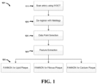
- method 101 comprises a first step 111 of scanning an artery to obtain intravascular optical coherence tomography images.
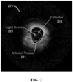
- An example of one such image 201 is provided in FIG. 2 .
- a catheter 211 with a light source 221 is used to image arterial tissue 231. It is understood that not all components of catheter 211 are labeled in FIG. 2 for purposes of clarity.
- such images may by obtained using optical coherence tomography systems and methods as disclosed in U.S. Patent Publications 2014/0268168 and 2016/0078309 .
- method 101 then co-registers image data with histological data in step 121, as described in more detail below.
- Image data point selection is performed in step 131, followed by feature extraction in step 141, also further discussed below.
- Feature and Node Optimized Neural Networks (FANONN) for different types of tissue e.g. lipid plaque, fibrous plaques, and calcific plaques
- FANONN Feature and Node Optimized Neural Networks
- image data point selection may be manually selected by a user (e.g. "point-and-click” selection), or via sampling from regions of interest in B-scans of the tissue. It is understood that the classification techniques disclosed herein may be applied to other tissue types (including non-diseased tissues) as well.
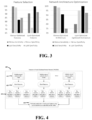
- FIG. 3 graphs are provided for feature selection and network architecture optimization for fibrous-optimized and lipid-optimized features and architecture. As shown in the graph on the left side of FIG. 3 , sensitivity and specificity is highest for a neural network with features selected to optimize for classification of a specific tissue. Lipid sensitivity and specificity is worse with a network running on features optimized for fibrous plaque. Likewise, fibrous sensitivity and specificity is worse with a network running on features optimized for lipid plaque.
- the graph on the right side of FIG. 3 illustrates that sensitivity and specificity is highest for a neural network with number of nodes (e.g. neurons) optimized for classification of a specific tissue type. Lipid sensitivity and specificity is worse with a network with number of nodes optimized for fibrous plaque. Likewise, fibrous tissue sensitivity and specificity is worse with a network with number of nodes optimized for lipid tissue. Accordingly, tissue classification is dependent on both the specific features used and the number of nodes comprising the network.
- nodes e.g. neurons
- exemplary embodiments co-register intravascular OCT image data with histological data.
- LAD left anterior descending artery
- RCA right coronary artery
- IVOCT imaging was conducted using a 1310 nm swept source laser (HSL-1000, Santec, Hackensack, NJ) with a bandwidth of 80 nm scanning, a repetition rate of 34 kHz, and a measured free-space axial resolution of 20 ⁇ m with a 2.8 mm scan depth.
- the IVOCT signal was sampled with a linear k-space clock to allow real-time OCT image acquisition and display.
- Per artery, 100 cross-section images (B-scans) were collected.
- a fluoroscopy system (GE Medical Systems) and a chamber designed to maintain the tissue at 37°C were used.
- Left and right coronary 6F guide catheters were sewn into the coronary ostia, 0.014 inch guide-wire access to the coronary arteries was gained under fluoroscopic guidance, and a stent was deployed 80 mm from the guide catheter tip as a fiduciary marker.
- IVOCT pullbacks were acquired from the stent to the guide catheter (80 mm total pullback length).
- the left anterior descending (LAD) artery and right coronary artery (RCA) were imaged. Following imaging, the RCA and LAD were perfusion-fixed with formalin at 100 mm Hg. Histology cross-sections were taken from the same 14 coronary arteries and 10 human hearts with 100 histology slices at the same depth as 100 cross-section B-scans for each artery.
- LADs and RCAs were perfusion-fixed with 10% neutral-buffered formalin, excised from each heart, individually radiographed on a Faxitron MX-20 (Faxitron Bioptics LLC, Arlington AZ), and decalcified overnight with Cal-Rite (Richard Allen Scientific) if necessary.
- the arterial segments were sliced into 2-3 mm thick rings and further processed on a Tissue-Tek Vacuum Infiltration Processor (Sakura Finetek USA, Torrance, CA) for standard paraffin-embedded sections. An average of 25 rings were generated from each artery.
- histology rings were then matched to respective IVOCT frames.
- Co-registration was performed between IVOCT images and histological sections based on the following: (1) two fiducial landmarks-a stent deployed at the distal end of the pullback and the sewn-in guide catheter at the proximal edge-that were visible in IVOCT images, fluoroscopy, and radiography before histopathological processing, and (2) the physical position of IVOCT images in the pullbacks measured against the estimated distance in microns from the fiducial landmarks in the tissue sections.
- the two-dimensional windowed image statistics are determined by generating a square window around a pixel of interest and calculating the following statistics:
- the intensity is defined as the backscattered light from the tissue measured in decibels.
- the attenuation data represents how the backscattered light intensity decays as a function of radial distance from the light source.
- the GLCM is a method for texture analysis and characterization based on the spatial relationship between pixels.
- image texture is characterized by determining the frequency with which pairs of pixels with certain values and a pre-defined spatial relationship occur.
- specific GLCM textural features include:
- Each of these textural features is again calculated with intensity and attenuation.
- the optimization process for the algorithm to classify each tissue type selects from these windowed and GLCM features. Additional discussion of GLCM can be found in Yang, Xiaofeng, et al. "Ultrasound GLCM texture analysis of radiation-induced parotid-gland injury in head-and-neck cancer radiotherapy: an in vivo study of late toxicity.” Medical physics 39.9 (2012): 5732-5739 .
- a classification technique uses an optimized neural network to classify plaque tissue from a set of images.
- a neural network has the ability to sort a dataset into many different classes.
- three different classes of tissue types are identified: lipid, calcium, and fibrous plaque. It is undertood that different embodiments may include different classes of tissue types.
- a set of quantitative image features is provided to the network as a basis for judgment and using these features, the neural network will make decisions as to what class to sort a pixel into.
- the sensitivity and specificity of a neural network can change based on the features that are provided to it. All of the available features to be inputted into the neural network are called candidate features. For example, if one has 300 candidate features to choose from, it might be found that the neural network functions best with a specific set of 150 of those features instead of the full 300. In order to best classify data, the best features should be selected amongst a pool of candidates. Having either too few or too many features than optimum can be damaging to the resulting sensitivity and specificity of the method.
- IVOCT expert imaging technicians typically use different features to classify different types of plaque. For example, when looking for fibrous plaque, imaging technicians will typically look for high backscattering and homogeneity whereas when searching for calcium plaque an expert might look at signal quality and delineation of tissue borders. Accordingly, it is not optimal to use a single network with a single set of features to classify all types of tissue.
- a set of features that work best for sorting fibrous plaque will not be the best features to use for sorting calcific plaque.
- the number of nodes comprising the neural network affects its performance with a given set of features.
- the optimal set of features and network structure are interdependent because the inputted features affect the optimal distribution of weights associated with the connections between nodes in the network and this can have an impact on sensitivity and specificity. Therefore, in order to construct an optimized network, one must optimize not only the features selected to classify the tissue but also the structure of a network based on the features used.
- exemplary embodiments of the present disclosure utilize a multiple-pass, co-optimized classification system for each tissue type.
- the method maximizes the sensitivity and specificity for each type of tissue.
- the classification system first gathers the quantitative image features associated with the IVOCT image data along with the truth data from co-registered histology slides of the tissue. Each type of tissue is handled individually.
- a first network is optimized to detect fibrous plaque, then another network is optimized to detect calcific plaque, and a third network is optimized to detect lipid plaque. It is understood, that for additional tissue classes, additional networks can be constructed.
- the feature and node optimized neural network (FANNON) optimization process 401 for each tissue begins by using each feature individually to evaluate the data with a neural network to sort each tissue type.
- the process begins by initializing a neural network with one node in step 411.
- the resulting sensitivity and specificity of each feature method is calculated using a receiver operating characteristic (ROC) curve which plots the true positive vs. false positive rates of the classifier.
- ROC receiver operating characteristic
- the greater the area under the ROC curve the greater the sensitivity and specificity of the neural network based on the feature.
- the features are all ranked according to the area under the ROC curves of the neural networks they serve as inputs to, from greatest sensitivity and specificity to least sensitivity and specificity.
- the classification system uses an increasing number of features from the ranked feature list, starting from 1 to the number of candidate features, and records the sensitivity and specificity of each group of features in step 431. This process is repeated for a range of neural network architectures, varying the number of nodes involved.
- the best combination of number of features and nodes used is selected based on the sum of sensitivity and specificity of the network to detect the specific type of tissue involved.
- the best network for each tissue type has a unique feature set and a unique number of nodes paired together, creating a Feature and Node Optimized Neural Network (FANONN) that is used to optimally classify each plaque type.
- FANONN Feature and Node Optimized Neural Network
- the FANONN classification algorithm of exemplary embodiments has been demonstrated to sort plaque tissue as fibrous, calcium, or lipid plaque as verified by histology analysis with sensitivities and specificities listed in the table below:
- the data presented in the table above compares results using FANNON techniques disclosed herein to studies in literature that attempt to automate the plaque classification process using IVOCT.
- the accuracy for each technique is the average of sensitivity and specificity, where the sensitivity is the proportion of the known plaque type data points that the algorithm correctly classifies and the specificity is the ratio of correct classifications to total classifications for a certain category of plaque.
- exemplary embodiments can further classify lipid lesions as the particularly high-risk TCFA type of lesion with 100% sensitivity and 100% specificity. Taken with the classification of lipid plaque as the limiting factor, the algorithm can detect TCFA lesions with 94% accuracy.
- the described classification techniques and systems can characterize arterial plaque tissue in the coronary artery into fibrous, calcium, or lipid plaque without any human input better than other reported methods.
- Other groups have conducted similar studies to automate the characterization of coronary plaque with similar motivations but have not had the same degree of success.
- Specific groups in the field include Ughi et al. who have achieved accuracies of 89.5%, 72%, and 79.5%, and Athanasiou et al. who have achieved accuracies of 81%, 87%, and 71% accuracies in automated characterization of fibrous, calcium, and lipid plaque, respectively.
- the current leading studies by Ughi and Athanasiou use human observers as their ground truth which makes their classification technique inherently less accurate.
- the present invention uses histology as the ground truth for training which improves accuracy and stability.
- Exemplary embodiments of the present disclosure achieve high accuracy through not only the use of histology as the reference truth but also through the classification techniques disclosed herein. Exemplary embodiments achieve improved results by treating each individual plaque type individually and allowing the creation of a tailored neural network structure to optimally classify each type. Such techniques provide for improved results for each plaque type and can be expanded to as many tissue types as desired.
- the FANONN classification method disclosed herein not only classifies plaque tissue composition with high accuracy but can also provide risk analysis of the tissue after classification.
- the classification method can identify plaque lesions as TCFA which are known to be indicative of unstable plaque and lead to a majority of acute coronary event such as plaque ruptures (Fujii et al, 2015). Such plaque ruptures can occlude a blood vessel, leading to heart attack or stroke.
- the FANONN smart algorithm paired with the micron-level resolution of IVOCT has both the physical resolution and machine intelligence required to accurately classify these risk-prone plaques. This ability of the classification method makes it very powerful but also special in that no other group in the world can provide automated analysis with a higher degree of accuracy.
- System 500 can be used to obtain images of tissue for analysis and classification as described herein.
- system 500 comprises an optical coherence tomography light source 510, a splitter 515, optical circulator 520, coupler 525 and balanced detector 530.
- Splitter 515 is configured to direct light from OCT light source 510 to a reference path 511 and a sample path 521.
- sample path 521 is directed through patient interface module 502 and catheter 501, while reference path 511 is directed to afiber reflector 512 via a photonic crystal fiber 513.
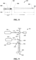
- FIG. 6 A perspective view of patient interface module 502 is shown in FIG. 6 , while a schematic view of catheter 501 is shown in FIG. 7 , and a partial section view of the distal end of catheter 501 is shown in FIG. 8 .
- catheter 501 comprises a bead 535 and an optical connector 534 near proximal end 532.
- patient interface module 502 is configured to control catheter 501 via a torque cable 509 (shown in FIG. 8 ) that transmits torque from patient interface module 502 to distal end 531 of cathether 501,
- patient interface module 502 can be configured to provide 100 mm of linear stroke to catheter 501 at variable translation speeds up to 50 mm per second in two directions (e.g. push forward or pull back).
- patient interface module 502 can be configured to rotate an imaging port 533 at speeds up to 3,600 revolutions per minute and obtain 1,000 A-scans per rotation.
- catheter 501 can be a sterile, single-use disposable catheter with a 3.2 F crossing profile and monorail design compatible with a 6F guide catheter and a 0.014 inch guide wire.
- catheter 501 may comprise a stationary outer sheath 551 with an imaging port 557, a rotating and translating torque cable 509 and optics assembly 552.
- catheter 501 comprises an optical fiber through its length, with an optic assembly (e.g. a ferrule, gradient index [GRIN] lens, and prism) near imaging port 557 and distal end 531 of catheter 501.
- an optic assembly e.g. a ferrule, gradient index [GRIN] lens, and prism
- catheter 501 may comprise a radiopaque marker 553 on the outer assembly near distal end 531, as well as a radiopaque marker 554 on the inner assembly near imaging port 557.
- catheter 501 may further comprise a guidewire exit port 558 near distal end 531. It is understood that the dimensions shown in FIGS. 7 and 8 are merely exemplary, and that other embodiments may comprise configurations with dimensions different from those shown in this embodiment.
- one exemplary embodiment of such an apparatus 50 comprises an optical coherence tomography light source 100, a splitter 200, a short pulsed (e.g. two-photon luminescence) excitation light source 300, a first dichroic element 400 and a second dichroic element 450. It is understood that other embodiments may comprise an apparatus with a different combination of components or fewer components than those shown in FIG. 9 .
- optical coherence tomography light source 100 is configured to emit a first wavelength 110 and splitter 200 is configured to direct first wavelength 110 to a reference path 210 and a sample path 220.
- optical coherence tomography light source 100 can be configured as a swept source optical coherence tomography light source or a broadband optical coherence tomography light source.
- sample path 220 can be directed through a photonic crystal fiber.
- two-photon luminescence excitation light source 300 is configured to emit a second wavelength 320.
- apparatus 50 can be positioned such that sample path 220 and second wavelength 320 are directed to a sample site 280 (e.g. via first dichroic element 400 as well as other components in FIG. 9 ).
- sample site 280 may comprise nanoparticles 260 and in specific embodiments, nanoparticles 260 may be configured as nanorods.
- nanoparticles 260 may be configured as nanorods comprising gold with a surface plasmon resonance of approximately 756 nm.
- the configuration of the nanorods can be selected according to the procedures established in the Example Section 4 provided below.
- Apparatus 50 further comprises a photon counting detector 350 configured to detect two-photon luminescence (TPL) and a balanced detector 250 configured to minimize a non-interfering OCT component.
- photon counting detector 350 can be configured as one or more photomultiplier tubes (PMTs).
- photon counting detector 350 can be configured as an avalanche photo diode.
- components of the system illustrated in FIG. 9 can be incorporated into a catheter-based system that utilizes a photonic crystal fiber (PCF) to enable the propagation of light in sample path 220 and second wavelength 320 from TPL excitation light source 300 to sample site 280.
- PCF photonic crystal fiber
- the PCF allows single-mode transmission of both OCT and TPL excitation light. Single-mode transmission is required in OCT imaging to insure the modal interference does not occur. Single mode transmission is required for TPL imaging to insure the pulse duration of TPL excitation light is not broadened due to modal dispersion.
- the catheter can be inserted into a blood vessel to obtain intravascular images utilizing system 50.
- system 50 provides the benefits of both OCT and TPL imaging technologies in a single system.
- the components of system 50 function according to established principles in OCT and TPL fields. Accordingly, while an overview of the individual OCT and TPL will be provided, it is understood that exemplary embodiments may utilize various combinations of parameters according to environmental conditions or other factors.
- OCT light source 100 can produce near-infrared light, and the use of relatively long wavelength light allows deeper penetration into the scattering medium such as an arterial wall.
- OCT light source 100 can be configured to provide light at a wavelength of approximately 1310 nm.
- sample path 220 As light in sample path 220 is directed at sample site 280, a small portion of this light that reflects from sub-surface features of sample site 280 is collected. During operation, a significant portion of light in sample path 220 is not reflected but, rather, backscatters from the sample. Although backscattered light contributes background that obscures an image in conventional imaging, this light can be used beneficially in OCT systems via interferometry.
- balanced detector 250 can be used to record the optical path length of received photons, allowing rejection of most photons that multiply scatter in the tissue before detection. This can allow recording three-dimensional images of thick samples to be constructed by rejecting background signal while collecting light directly reflected from regions of interest in sample site 280.
- OCT imaging is generally limited to one to two millimeters below the surface in biological tissue in sample site 280. At greater depths, the proportion of light that escapes without scattering is typically too small for detection.
- TPL light source 300 and photon counting detector 350 are also utilized consistent with established principles in two-photon luminescence microscopy.
- TPL light source 300 can be configured as a tunable femtosecond laser producing excitation energy of second wavelength 320 at 760-1040 nm with a maximum pulse energy of 6 nJ-5 ⁇ J, a pulse width of 100 fs-1 ps, and a repetition rate of 500 kHz-80 MHz.
- TPL light source 300 may also be configured to produce a spot size of 10-30 ⁇ m with a spot area of approximately 78-706.8 ⁇ m 2 and a pixel dwell time of 20 ⁇ s.
- TPL light source 300 may also be configured to produce 10-1600 pulses per pixel, with an average power on sample of 500-2500 mW, an instantaneous power of 0.0625-5 MW and an instantaneous power density of 2E-4-16E-3 MW/ ⁇ m 2 .
- first dichroic element 400 can be positioned to direct second wavelength 320 to sample site 280 via a photonic crystal fiber (PCF).
- the PCF can have a large sized mode field diameter (20 ⁇ m) (LMA-20) available from NKT Photonics.
- the PCF may be configured as a double-clad fiber, and in specific embodiments, may be a double-clad high NA fiber such as a model number DC-165-16-Passive Fiber available from Crystal Fibre.
- Exemplary double-clad photonic crystal fibers may comprise a large-mode area, single-mode core embedded in a high-NA multimode fiber structure.
- Such fibers can allow a single-mode beam to be propagated forward in the fiber and at the same time scattered light or two-photon luminescence may be collected and propagated backwards for detection.
- the use of a double-clad fiber instead of a single-clad photonic crystal fiber can increase the two-photon luminescence detection efficiency with a high-NA inner cladding (compared to the low-NA core).
- second wavelength 320 can provide excitation energy to nanoparticles 260, which can emit luminescence 270 that is directed to photon counting detector 350 via second dichroic element 450.
- the outputs from the photon counting detector 350 and balanced detector 250 can be configured to be combined in a single display that allows a user to visualize the results of both OCT and TPL imaging overlayed.
Landscapes
- Health & Medical Sciences (AREA)
- Life Sciences & Earth Sciences (AREA)
- Engineering & Computer Science (AREA)
- Physics & Mathematics (AREA)
- Medical Informatics (AREA)
- General Health & Medical Sciences (AREA)
- Surgery (AREA)
- Public Health (AREA)
- Biomedical Technology (AREA)
- Heart & Thoracic Surgery (AREA)
- Biophysics (AREA)
- Molecular Biology (AREA)
- Veterinary Medicine (AREA)
- Animal Behavior & Ethology (AREA)
- Pathology (AREA)
- Radiology & Medical Imaging (AREA)
- Nuclear Medicine, Radiotherapy & Molecular Imaging (AREA)
- Computer Vision & Pattern Recognition (AREA)
- Theoretical Computer Science (AREA)
- Artificial Intelligence (AREA)
- General Physics & Mathematics (AREA)
- Evolutionary Computation (AREA)
- Physiology (AREA)
- Mathematical Physics (AREA)
- Signal Processing (AREA)
- Fuzzy Systems (AREA)
- Quality & Reliability (AREA)
- Psychiatry (AREA)
- Optics & Photonics (AREA)
- High Energy & Nuclear Physics (AREA)
- Bioinformatics & Computational Biology (AREA)
- Bioinformatics & Cheminformatics (AREA)
- Data Mining & Analysis (AREA)
- Evolutionary Biology (AREA)
- General Engineering & Computer Science (AREA)
- Computing Systems (AREA)
- Vascular Medicine (AREA)
- Probability & Statistics with Applications (AREA)
- Cardiology (AREA)
- Investigating Or Analysing Materials By Optical Means (AREA)
Applications Claiming Priority (2)
| Application Number | Priority Date | Filing Date | Title |
|---|---|---|---|
| US201662347379P | 2016-06-08 | 2016-06-08 | |
| PCT/US2017/036587 WO2017214421A1 (en) | 2016-06-08 | 2017-06-08 | Systems and methods for automated coronary plaque characterization and risk assessment using intravascular optical coherence tomography |
Publications (3)
| Publication Number | Publication Date |
|---|---|
| EP3468453A1 EP3468453A1 (en) | 2019-04-17 |
| EP3468453A4 EP3468453A4 (en) | 2020-01-01 |
| EP3468453B1 true EP3468453B1 (en) | 2023-12-27 |
Family
ID=60578977
Family Applications (1)
| Application Number | Title | Priority Date | Filing Date |
|---|---|---|---|
| EP17811024.3A Active EP3468453B1 (en) | 2016-06-08 | 2017-06-08 | Systems and methods for automated coronary plaque characterization and risk assessment using intravascular optical coherence tomography |
Country Status (7)
| Country | Link |
|---|---|
| US (1) | US12213810B2 (enExample) |
| EP (1) | EP3468453B1 (enExample) |
| JP (2) | JP7058264B2 (enExample) |
| KR (1) | KR102531819B1 (enExample) |
| AU (1) | AU2017277784B2 (enExample) |
| CA (1) | CA3026650A1 (enExample) |
| WO (1) | WO2017214421A1 (enExample) |
Families Citing this family (19)
| Publication number | Priority date | Publication date | Assignee | Title |
|---|---|---|---|---|
| CN107945176B (zh) * | 2017-12-15 | 2021-05-11 | 西安中科微光影像技术有限公司 | 一种彩色ivoct成像方法 |
| CN108171702A (zh) * | 2018-01-18 | 2018-06-15 | 平安科技(深圳)有限公司 | 易损斑块识别方法、应用服务器及计算机可读存储介质 |
| CN108416769B (zh) * | 2018-03-02 | 2021-06-04 | 成都斯斐德科技有限公司 | 基于预处理的ivoct图像易损斑块自动检测方法 |
| US11721439B2 (en) * | 2018-03-08 | 2023-08-08 | Koninklijke Philips N.V. | Resolving and steering decision foci in machine learning-based vascular imaging |
| EP3893734A4 (en) * | 2018-12-14 | 2022-08-10 | Research Development Foundation | MULTICHANNEL ORTHOGONAL CONVOLUTIONAL NEURAL NETWORKS |
| JP7626704B2 (ja) | 2019-01-13 | 2025-02-04 | ライトラボ・イメージング・インコーポレーテッド | 動脈画像領域及びそれらの特徴を分類するシステム及びその作動方法 |
| GB201906103D0 (en) | 2019-05-01 | 2019-06-12 | Cambridge Entpr Ltd | Method and apparatus for analysing intracoronary images |
| CN116884580A (zh) | 2019-08-05 | 2023-10-13 | 光实验成像公司 | 用于提供冠状动脉钙负荷的纵向显示的装置和方法 |
| KR102261111B1 (ko) * | 2019-09-10 | 2021-06-04 | 인하대학교 산학협력단 | Gan을 이용한 의료 영상의 광강도 분포 일반화 기법 |
| CN115701939A (zh) * | 2020-03-30 | 2023-02-14 | 泰尔茂株式会社 | 程序、信息处理方法、学习模型的生成方法、学习模型的再学习方法及信息处理系统 |
| US20230162356A1 (en) * | 2020-04-10 | 2023-05-25 | Japanese Foundation For Cancer Research | Diagnostic imaging device, diagnostic imaging method, diagnostic imaging program, and learned model |
| JP7667852B2 (ja) * | 2020-08-06 | 2025-04-23 | キヤノン ユーエスエイ,インコーポレイテッド | カテーテルベースのマルチモーダル画像における潜在的な偽陽性及び盲点の位置を特定するためのシステム及び方法 |
| CN114792374A (zh) * | 2021-01-23 | 2022-07-26 | 富泰华工业(深圳)有限公司 | 基于纹理分类的图像识别方法、电子装置及存储介质 |
| CN112957012B (zh) * | 2021-02-01 | 2022-09-30 | 浙江省医疗器械检验研究院 | 一种光学干涉断层成像系统轴向分辨率测量装置及测量方法 |
| WO2022202320A1 (ja) * | 2021-03-25 | 2022-09-29 | テルモ株式会社 | プログラム、情報処理方法及び情報処理装置 |
| EP4195215A1 (en) * | 2021-12-08 | 2023-06-14 | Koninklijke Philips N.V. | Thrombus treatment metric |
| KR102656944B1 (ko) * | 2021-12-21 | 2024-04-16 | 주식회사 레이와트 | 기계 학습 기반의 분획혈류예비력 예측 방법 |
| EP4361941A1 (en) * | 2022-10-27 | 2024-05-01 | Carl Zeiss Meditec AG | Method, processor unit and system for processing of images |
| CN115436239B (zh) * | 2022-11-07 | 2023-02-07 | 四川亿欣新材料有限公司 | 一种碳酸钙颗粒度检测方法 |
Family Cites Families (22)
| Publication number | Priority date | Publication date | Assignee | Title |
|---|---|---|---|---|
| US6141437A (en) * | 1995-11-22 | 2000-10-31 | Arch Development Corporation | CAD method, computer and storage medium for automated detection of lung nodules in digital chest images |
| US5995651A (en) | 1996-07-11 | 1999-11-30 | Duke University | Image content classification methods, systems and computer programs using texture patterns |
| DE10297689B4 (de) | 2001-05-01 | 2007-10-18 | The General Hospital Corp., Boston | Verfahren und Gerät zur Bestimmung von atherosklerotischem Belag durch Messung von optischen Gewebeeigenschaften |
| US7075658B2 (en) * | 2003-01-24 | 2006-07-11 | Duke University | Method for optical coherence tomography imaging with molecular contrast |
| DE102005010076A1 (de) | 2005-03-04 | 2006-09-07 | Siemens Ag | Bildbearbeitungsverfahren für ein digitales medizinisches Untersuchungsbild und zugehörige Untersuchungseinrichtung |
| CN102046071B (zh) | 2008-06-02 | 2013-11-06 | 光学实验室成像公司 | 用于从光学相干断层扫描图像获得组织特性的定量方法 |
| US9351642B2 (en) * | 2009-03-12 | 2016-05-31 | The General Hospital Corporation | Non-contact optical system, computer-accessible medium and method for measurement at least one mechanical property of tissue using coherent speckle technique(s) |
| US20120163693A1 (en) | 2010-04-20 | 2012-06-28 | Suri Jasjit S | Non-Invasive Imaging-Based Prostate Cancer Prediction |
| US20110257545A1 (en) * | 2010-04-20 | 2011-10-20 | Suri Jasjit S | Imaging based symptomatic classification and cardiovascular stroke risk score estimation |
| US20110257505A1 (en) * | 2010-04-20 | 2011-10-20 | Suri Jasjit S | Atheromatic?: imaging based symptomatic classification and cardiovascular stroke index estimation |
| US8532360B2 (en) * | 2010-04-20 | 2013-09-10 | Atheropoint Llc | Imaging based symptomatic classification using a combination of trace transform, fuzzy technique and multitude of features |
| MX355020B (es) * | 2010-07-09 | 2018-04-02 | Somalogic Inc | Biomarcadores de cancer de pulmon y usos de los mismos. |
| WO2012082804A2 (en) * | 2010-12-13 | 2012-06-21 | Georg-August-Universität Göttingen | Medical imaging devices, methods, and systems |
| US9504374B2 (en) * | 2012-06-01 | 2016-11-29 | Nkt Photonics A/S | Supercontinuum light source, a system and a method of measuring |
| ITMI20121156A1 (it) * | 2012-06-29 | 2013-12-30 | Consiglio Nazionale Ricerche | Metodo di elaborazione di immagini di tomografia a coerenza ottica |
| CN104769481B (zh) | 2012-10-12 | 2018-12-18 | 统雷有限公司 | 紧凑、低色散以及低像差自适应光学扫描系统 |
| WO2014138555A1 (en) * | 2013-03-07 | 2014-09-12 | Bernhard Sturm | Multimodal segmentation in intravascular images |
| CA2903201C (en) | 2013-03-14 | 2023-02-21 | Research Development Foundation | Apparatus and methods for optical coherence tomography and two-photon luminescence imaging |
| WO2016040775A2 (en) | 2014-09-12 | 2016-03-17 | Research Development Foundation | Apparatus and methods for identifyhing and evaluating bright spot indications observed through optical coherence tomography |
| KR102294734B1 (ko) * | 2014-09-30 | 2021-08-30 | 삼성전자주식회사 | 영상 정합 장치, 영상 정합 방법 및 영상 정합 장치가 마련된 초음파 진단 장치 |
| US11094058B2 (en) * | 2015-08-14 | 2021-08-17 | Elucid Bioimaging Inc. | Systems and method for computer-aided phenotyping (CAP) using radiologic images |
| WO2018005623A1 (en) * | 2016-06-28 | 2018-01-04 | The Regents Of The University Of California | Fast two-photon imaging by diffracted swept-laser excitation |
-
2017
- 2017-06-08 KR KR1020197000509A patent/KR102531819B1/ko active Active
- 2017-06-08 EP EP17811024.3A patent/EP3468453B1/en active Active
- 2017-06-08 JP JP2019516914A patent/JP7058264B2/ja active Active
- 2017-06-08 US US16/308,081 patent/US12213810B2/en active Active
- 2017-06-08 WO PCT/US2017/036587 patent/WO2017214421A1/en not_active Ceased
- 2017-06-08 CA CA3026650A patent/CA3026650A1/en active Pending
- 2017-06-08 AU AU2017277784A patent/AU2017277784B2/en not_active Ceased
-
2022
- 2022-04-11 JP JP2022064872A patent/JP7383070B2/ja active Active
Also Published As
| Publication number | Publication date |
|---|---|
| KR20190015546A (ko) | 2019-02-13 |
| US12213810B2 (en) | 2025-02-04 |
| EP3468453A1 (en) | 2019-04-17 |
| EP3468453A4 (en) | 2020-01-01 |
| JP7383070B2 (ja) | 2023-11-17 |
| JP2022095854A (ja) | 2022-06-28 |
| US20230083484A1 (en) | 2023-03-16 |
| JP7058264B2 (ja) | 2022-04-21 |
| WO2017214421A1 (en) | 2017-12-14 |
| AU2017277784B2 (en) | 2022-06-30 |
| KR102531819B1 (ko) | 2023-05-16 |
| JP2019518581A (ja) | 2019-07-04 |
| CA3026650A1 (en) | 2017-12-14 |
| AU2017277784A1 (en) | 2018-12-20 |
Similar Documents
| Publication | Publication Date | Title |
|---|---|---|
| JP7383070B2 (ja) | 血管内光干渉断層撮影法を用いた冠動脈プラークの自動特徴分析およびリスク評価のためのシステムおよび方法 | |
| AU2019397494B2 (en) | Multi-channel orthogonal convolutional neural networks | |
| US9633277B2 (en) | Apparatus and methods for identifying and evaluating bright spot indications observed through optical coherence tomography | |
| US10495440B2 (en) | Apparatus and methods for optical coherence tomography and two-photon luminescence imaging | |
| US6091984A (en) | Measuring tissue morphology | |
| Lee et al. | Comprehensive intravascular imaging of atherosclerotic plaque in vivo using optical coherence tomography and fluorescence lifetime imaging | |
| Marcu | Fluorescence lifetime in cardiovascular diagnostics | |
| Richards-Kortum et al. | 476 nm excited laser-induced fluorescence spectroscopy of human coronary arteries: applications in cardiology | |
| JP2015516847A (ja) | アテローム斑の検出 | |
| Poneros et al. | Diagnosis of Barrett's esophagus using optical coherence tomography | |
| Villiger et al. | Future development | |
| Wilson | Medical Diagnostics | |
| Faber et al. | NAOMI: Nanoparticle assisted optical molecular imaging | |
| Phipps et al. | Endoscopic fluorescence lifetime imaging microscopy (FLIM) images of aortic plaque: an automated classification method | |
| HK1217227B (zh) | 用於光学相干断层扫描和双光子荧光成像的设备和方法 | |
| Dana et al. | Conference 9303E: Diagnostic and Therapeutic Applications of Light in Cardiology | |
| Thomas | Detection of Atherosclerotic Coronary Plaques by Fluorescence Lifetime Imaging Angioscopy |
Legal Events
| Date | Code | Title | Description |
|---|---|---|---|
| STAA | Information on the status of an ep patent application or granted ep patent |
Free format text: STATUS: THE INTERNATIONAL PUBLICATION HAS BEEN MADE |
|
| PUAI | Public reference made under article 153(3) epc to a published international application that has entered the european phase |
Free format text: ORIGINAL CODE: 0009012 |
|
| STAA | Information on the status of an ep patent application or granted ep patent |
Free format text: STATUS: REQUEST FOR EXAMINATION WAS MADE |
|
| 17P | Request for examination filed |
Effective date: 20190104 |
|
| AK | Designated contracting states |
Kind code of ref document: A1 Designated state(s): AL AT BE BG CH CY CZ DE DK EE ES FI FR GB GR HR HU IE IS IT LI LT LU LV MC MK MT NL NO PL PT RO RS SE SI SK SM TR |
|
| AX | Request for extension of the european patent |
Extension state: BA ME |
|
| DAV | Request for validation of the european patent (deleted) | ||
| DAX | Request for extension of the european patent (deleted) | ||
| A4 | Supplementary search report drawn up and despatched |
Effective date: 20191129 |
|
| RIC1 | Information provided on ipc code assigned before grant |
Ipc: A61B 6/00 20060101ALI20191125BHEP Ipc: G06K 7/00 20060101ALI20191125BHEP Ipc: A61B 5/055 20060101ALI20191125BHEP Ipc: G06K 9/00 20060101ALI20191125BHEP Ipc: A61B 6/03 20060101ALI20191125BHEP Ipc: A61B 5/00 20060101AFI20191125BHEP Ipc: A61B 5/02 20060101ALI20191125BHEP |
|
| RIC1 | Information provided on ipc code assigned before grant |
Ipc: G06K 7/00 20060101ALI20230208BHEP Ipc: A61B 5/02 20060101ALI20230208BHEP Ipc: A61B 5/00 20060101AFI20230208BHEP |
|
| GRAP | Despatch of communication of intention to grant a patent |
Free format text: ORIGINAL CODE: EPIDOSNIGR1 |
|
| STAA | Information on the status of an ep patent application or granted ep patent |
Free format text: STATUS: GRANT OF PATENT IS INTENDED |
|
| INTG | Intention to grant announced |
Effective date: 20230710 |
|
| GRAS | Grant fee paid |
Free format text: ORIGINAL CODE: EPIDOSNIGR3 |
|
| GRAA | (expected) grant |
Free format text: ORIGINAL CODE: 0009210 |
|
| STAA | Information on the status of an ep patent application or granted ep patent |
Free format text: STATUS: THE PATENT HAS BEEN GRANTED |
|
| AK | Designated contracting states |
Kind code of ref document: B1 Designated state(s): AL AT BE BG CH CY CZ DE DK EE ES FI FR GB GR HR HU IE IS IT LI LT LU LV MC MK MT NL NO PL PT RO RS SE SI SK SM TR |
|
| REG | Reference to a national code |
Ref country code: GB Ref legal event code: FG4D |
|
| REG | Reference to a national code |
Ref country code: CH Ref legal event code: EP |
|
| REG | Reference to a national code |
Ref country code: DE Ref legal event code: R096 Ref document number: 602017077966 Country of ref document: DE |
|
| REG | Reference to a national code |
Ref country code: IE Ref legal event code: FG4D |
|
| P01 | Opt-out of the competence of the unified patent court (upc) registered |
Effective date: 20240123 |
|
| PG25 | Lapsed in a contracting state [announced via postgrant information from national office to epo] |
Ref country code: GR Free format text: LAPSE BECAUSE OF FAILURE TO SUBMIT A TRANSLATION OF THE DESCRIPTION OR TO PAY THE FEE WITHIN THE PRESCRIBED TIME-LIMIT Effective date: 20240328 |
|
| REG | Reference to a national code |
Ref country code: LT Ref legal event code: MG9D |
|
| PG25 | Lapsed in a contracting state [announced via postgrant information from national office to epo] |
Ref country code: LT Free format text: LAPSE BECAUSE OF FAILURE TO SUBMIT A TRANSLATION OF THE DESCRIPTION OR TO PAY THE FEE WITHIN THE PRESCRIBED TIME-LIMIT Effective date: 20231227 |
|
| PG25 | Lapsed in a contracting state [announced via postgrant information from national office to epo] |
Ref country code: ES Free format text: LAPSE BECAUSE OF FAILURE TO SUBMIT A TRANSLATION OF THE DESCRIPTION OR TO PAY THE FEE WITHIN THE PRESCRIBED TIME-LIMIT Effective date: 20231227 |
|
| PG25 | Lapsed in a contracting state [announced via postgrant information from national office to epo] |
Ref country code: LT Free format text: LAPSE BECAUSE OF FAILURE TO SUBMIT A TRANSLATION OF THE DESCRIPTION OR TO PAY THE FEE WITHIN THE PRESCRIBED TIME-LIMIT Effective date: 20231227 Ref country code: GR Free format text: LAPSE BECAUSE OF FAILURE TO SUBMIT A TRANSLATION OF THE DESCRIPTION OR TO PAY THE FEE WITHIN THE PRESCRIBED TIME-LIMIT Effective date: 20240328 Ref country code: FI Free format text: LAPSE BECAUSE OF FAILURE TO SUBMIT A TRANSLATION OF THE DESCRIPTION OR TO PAY THE FEE WITHIN THE PRESCRIBED TIME-LIMIT Effective date: 20231227 Ref country code: ES Free format text: LAPSE BECAUSE OF FAILURE TO SUBMIT A TRANSLATION OF THE DESCRIPTION OR TO PAY THE FEE WITHIN THE PRESCRIBED TIME-LIMIT Effective date: 20231227 Ref country code: BG Free format text: LAPSE BECAUSE OF FAILURE TO SUBMIT A TRANSLATION OF THE DESCRIPTION OR TO PAY THE FEE WITHIN THE PRESCRIBED TIME-LIMIT Effective date: 20240327 |
|
| REG | Reference to a national code |
Ref country code: NL Ref legal event code: MP Effective date: 20231227 |
|
| REG | Reference to a national code |
Ref country code: AT Ref legal event code: MK05 Ref document number: 1643743 Country of ref document: AT Kind code of ref document: T Effective date: 20231227 |
|
| PG25 | Lapsed in a contracting state [announced via postgrant information from national office to epo] |
Ref country code: NL Free format text: LAPSE BECAUSE OF FAILURE TO SUBMIT A TRANSLATION OF THE DESCRIPTION OR TO PAY THE FEE WITHIN THE PRESCRIBED TIME-LIMIT Effective date: 20231227 |
|
| PG25 | Lapsed in a contracting state [announced via postgrant information from national office to epo] |
Ref country code: SE Free format text: LAPSE BECAUSE OF FAILURE TO SUBMIT A TRANSLATION OF THE DESCRIPTION OR TO PAY THE FEE WITHIN THE PRESCRIBED TIME-LIMIT Effective date: 20231227 Ref country code: RS Free format text: LAPSE BECAUSE OF FAILURE TO SUBMIT A TRANSLATION OF THE DESCRIPTION OR TO PAY THE FEE WITHIN THE PRESCRIBED TIME-LIMIT Effective date: 20231227 Ref country code: NO Free format text: LAPSE BECAUSE OF FAILURE TO SUBMIT A TRANSLATION OF THE DESCRIPTION OR TO PAY THE FEE WITHIN THE PRESCRIBED TIME-LIMIT Effective date: 20240327 Ref country code: NL Free format text: LAPSE BECAUSE OF FAILURE TO SUBMIT A TRANSLATION OF THE DESCRIPTION OR TO PAY THE FEE WITHIN THE PRESCRIBED TIME-LIMIT Effective date: 20231227 Ref country code: LV Free format text: LAPSE BECAUSE OF FAILURE TO SUBMIT A TRANSLATION OF THE DESCRIPTION OR TO PAY THE FEE WITHIN THE PRESCRIBED TIME-LIMIT Effective date: 20231227 Ref country code: HR Free format text: LAPSE BECAUSE OF FAILURE TO SUBMIT A TRANSLATION OF THE DESCRIPTION OR TO PAY THE FEE WITHIN THE PRESCRIBED TIME-LIMIT Effective date: 20231227 |
|
| PG25 | Lapsed in a contracting state [announced via postgrant information from national office to epo] |
Ref country code: IS Free format text: LAPSE BECAUSE OF FAILURE TO SUBMIT A TRANSLATION OF THE DESCRIPTION OR TO PAY THE FEE WITHIN THE PRESCRIBED TIME-LIMIT Effective date: 20240427 |
|
| PGFP | Annual fee paid to national office [announced via postgrant information from national office to epo] |
Ref country code: GB Payment date: 20240625 Year of fee payment: 8 |
|
| PGFP | Annual fee paid to national office [announced via postgrant information from national office to epo] |
Ref country code: DE Payment date: 20240626 Year of fee payment: 8 |
|
| PG25 | Lapsed in a contracting state [announced via postgrant information from national office to epo] |
Ref country code: AT Free format text: LAPSE BECAUSE OF FAILURE TO SUBMIT A TRANSLATION OF THE DESCRIPTION OR TO PAY THE FEE WITHIN THE PRESCRIBED TIME-LIMIT Effective date: 20231227 Ref country code: CZ Free format text: LAPSE BECAUSE OF FAILURE TO SUBMIT A TRANSLATION OF THE DESCRIPTION OR TO PAY THE FEE WITHIN THE PRESCRIBED TIME-LIMIT Effective date: 20231227 |
|
| PG25 | Lapsed in a contracting state [announced via postgrant information from national office to epo] |
Ref country code: SK Free format text: LAPSE BECAUSE OF FAILURE TO SUBMIT A TRANSLATION OF THE DESCRIPTION OR TO PAY THE FEE WITHIN THE PRESCRIBED TIME-LIMIT Effective date: 20231227 |
|
| PG25 | Lapsed in a contracting state [announced via postgrant information from national office to epo] |
Ref country code: SM Free format text: LAPSE BECAUSE OF FAILURE TO SUBMIT A TRANSLATION OF THE DESCRIPTION OR TO PAY THE FEE WITHIN THE PRESCRIBED TIME-LIMIT Effective date: 20231227 Ref country code: SK Free format text: LAPSE BECAUSE OF FAILURE TO SUBMIT A TRANSLATION OF THE DESCRIPTION OR TO PAY THE FEE WITHIN THE PRESCRIBED TIME-LIMIT Effective date: 20231227 Ref country code: RO Free format text: LAPSE BECAUSE OF FAILURE TO SUBMIT A TRANSLATION OF THE DESCRIPTION OR TO PAY THE FEE WITHIN THE PRESCRIBED TIME-LIMIT Effective date: 20231227 Ref country code: IT Free format text: LAPSE BECAUSE OF FAILURE TO SUBMIT A TRANSLATION OF THE DESCRIPTION OR TO PAY THE FEE WITHIN THE PRESCRIBED TIME-LIMIT Effective date: 20231227 Ref country code: IS Free format text: LAPSE BECAUSE OF FAILURE TO SUBMIT A TRANSLATION OF THE DESCRIPTION OR TO PAY THE FEE WITHIN THE PRESCRIBED TIME-LIMIT Effective date: 20240427 Ref country code: EE Free format text: LAPSE BECAUSE OF FAILURE TO SUBMIT A TRANSLATION OF THE DESCRIPTION OR TO PAY THE FEE WITHIN THE PRESCRIBED TIME-LIMIT Effective date: 20231227 Ref country code: CZ Free format text: LAPSE BECAUSE OF FAILURE TO SUBMIT A TRANSLATION OF THE DESCRIPTION OR TO PAY THE FEE WITHIN THE PRESCRIBED TIME-LIMIT Effective date: 20231227 Ref country code: AT Free format text: LAPSE BECAUSE OF FAILURE TO SUBMIT A TRANSLATION OF THE DESCRIPTION OR TO PAY THE FEE WITHIN THE PRESCRIBED TIME-LIMIT Effective date: 20231227 |
|
| PGFP | Annual fee paid to national office [announced via postgrant information from national office to epo] |
Ref country code: FR Payment date: 20240626 Year of fee payment: 8 |
|
| PG25 | Lapsed in a contracting state [announced via postgrant information from national office to epo] |
Ref country code: PT Free format text: LAPSE BECAUSE OF FAILURE TO SUBMIT A TRANSLATION OF THE DESCRIPTION OR TO PAY THE FEE WITHIN THE PRESCRIBED TIME-LIMIT Effective date: 20240429 Ref country code: PL Free format text: LAPSE BECAUSE OF FAILURE TO SUBMIT A TRANSLATION OF THE DESCRIPTION OR TO PAY THE FEE WITHIN THE PRESCRIBED TIME-LIMIT Effective date: 20231227 |
|
| REG | Reference to a national code |
Ref country code: DE Ref legal event code: R097 Ref document number: 602017077966 Country of ref document: DE |
|
| PG25 | Lapsed in a contracting state [announced via postgrant information from national office to epo] |
Ref country code: DK Free format text: LAPSE BECAUSE OF FAILURE TO SUBMIT A TRANSLATION OF THE DESCRIPTION OR TO PAY THE FEE WITHIN THE PRESCRIBED TIME-LIMIT Effective date: 20231227 |
|
| PG25 | Lapsed in a contracting state [announced via postgrant information from national office to epo] |
Ref country code: DK Free format text: LAPSE BECAUSE OF FAILURE TO SUBMIT A TRANSLATION OF THE DESCRIPTION OR TO PAY THE FEE WITHIN THE PRESCRIBED TIME-LIMIT Effective date: 20231227 |
|
| PLBE | No opposition filed within time limit |
Free format text: ORIGINAL CODE: 0009261 |
|
| STAA | Information on the status of an ep patent application or granted ep patent |
Free format text: STATUS: NO OPPOSITION FILED WITHIN TIME LIMIT |
|
| 26N | No opposition filed |
Effective date: 20240930 |
|
| PG25 | Lapsed in a contracting state [announced via postgrant information from national office to epo] |
Ref country code: MC Free format text: LAPSE BECAUSE OF FAILURE TO SUBMIT A TRANSLATION OF THE DESCRIPTION OR TO PAY THE FEE WITHIN THE PRESCRIBED TIME-LIMIT Effective date: 20231227 |
|
| REG | Reference to a national code |
Ref country code: CH Ref legal event code: PL |
|
| PG25 | Lapsed in a contracting state [announced via postgrant information from national office to epo] |
Ref country code: LU Free format text: LAPSE BECAUSE OF NON-PAYMENT OF DUE FEES Effective date: 20240608 |
|
| PG25 | Lapsed in a contracting state [announced via postgrant information from national office to epo] |
Ref country code: IE Free format text: LAPSE BECAUSE OF NON-PAYMENT OF DUE FEES Effective date: 20240608 |
|
| PG25 | Lapsed in a contracting state [announced via postgrant information from national office to epo] |
Ref country code: CH Free format text: LAPSE BECAUSE OF NON-PAYMENT OF DUE FEES Effective date: 20240630 Ref country code: BE Free format text: LAPSE BECAUSE OF NON-PAYMENT OF DUE FEES Effective date: 20240630 Ref country code: SI Free format text: LAPSE BECAUSE OF FAILURE TO SUBMIT A TRANSLATION OF THE DESCRIPTION OR TO PAY THE FEE WITHIN THE PRESCRIBED TIME-LIMIT Effective date: 20231227 |
|
| REG | Reference to a national code |
Ref country code: BE Ref legal event code: MM Effective date: 20240630 |
|
| PG25 | Lapsed in a contracting state [announced via postgrant information from national office to epo] |
Ref country code: CY Free format text: LAPSE BECAUSE OF FAILURE TO SUBMIT A TRANSLATION OF THE DESCRIPTION OR TO PAY THE FEE WITHIN THE PRESCRIBED TIME-LIMIT; INVALID AB INITIO Effective date: 20170608 |