EP3467967A1 - Rotary connector - Google Patents
Rotary connector Download PDFInfo
- Publication number
- EP3467967A1 EP3467967A1 EP17806106.5A EP17806106A EP3467967A1 EP 3467967 A1 EP3467967 A1 EP 3467967A1 EP 17806106 A EP17806106 A EP 17806106A EP 3467967 A1 EP3467967 A1 EP 3467967A1
- Authority
- EP
- European Patent Office
- Prior art keywords
- main
- flexible printed
- printed circuit
- fpc
- sub
- Prior art date
- Legal status (The legal status is an assumption and is not a legal conclusion. Google has not performed a legal analysis and makes no representation as to the accuracy of the status listed.)
- Granted
Links
Images








Classifications
-
- H—ELECTRICITY
- H01—ELECTRIC ELEMENTS
- H01R—ELECTRICALLY-CONDUCTIVE CONNECTIONS; STRUCTURAL ASSOCIATIONS OF A PLURALITY OF MUTUALLY-INSULATED ELECTRICAL CONNECTING ELEMENTS; COUPLING DEVICES; CURRENT COLLECTORS
- H01R35/00—Flexible or turnable line connectors, i.e. the rotation angle being limited
- H01R35/02—Flexible line connectors without frictional contact members
- H01R35/025—Flexible line connectors without frictional contact members having a flexible conductor wound around a rotation axis
-
- B—PERFORMING OPERATIONS; TRANSPORTING
- B60—VEHICLES IN GENERAL
- B60R—VEHICLES, VEHICLE FITTINGS, OR VEHICLE PARTS, NOT OTHERWISE PROVIDED FOR
- B60R16/00—Electric or fluid circuits specially adapted for vehicles and not otherwise provided for; Arrangement of elements of electric or fluid circuits specially adapted for vehicles and not otherwise provided for
- B60R16/02—Electric or fluid circuits specially adapted for vehicles and not otherwise provided for; Arrangement of elements of electric or fluid circuits specially adapted for vehicles and not otherwise provided for electric constitutive elements
- B60R16/023—Electric or fluid circuits specially adapted for vehicles and not otherwise provided for; Arrangement of elements of electric or fluid circuits specially adapted for vehicles and not otherwise provided for electric constitutive elements for transmission of signals between vehicle parts or subsystems
- B60R16/027—Electric or fluid circuits specially adapted for vehicles and not otherwise provided for; Arrangement of elements of electric or fluid circuits specially adapted for vehicles and not otherwise provided for electric constitutive elements for transmission of signals between vehicle parts or subsystems between relatively movable parts of the vehicle, e.g. between steering wheel and column
-
- H—ELECTRICITY
- H01—ELECTRIC ELEMENTS
- H01R—ELECTRICALLY-CONDUCTIVE CONNECTIONS; STRUCTURAL ASSOCIATIONS OF A PLURALITY OF MUTUALLY-INSULATED ELECTRICAL CONNECTING ELEMENTS; COUPLING DEVICES; CURRENT COLLECTORS
- H01R12/00—Structural associations of a plurality of mutually-insulated electrical connecting elements, specially adapted for printed circuits, e.g. printed circuit boards [PCB], flat or ribbon cables, or like generally planar structures, e.g. terminal strips, terminal blocks; Coupling devices specially adapted for printed circuits, flat or ribbon cables, or like generally planar structures; Terminals specially adapted for contact with, or insertion into, printed circuits, flat or ribbon cables, or like generally planar structures
- H01R12/50—Fixed connections
- H01R12/59—Fixed connections for flexible printed circuits, flat or ribbon cables or like structures
- H01R12/61—Fixed connections for flexible printed circuits, flat or ribbon cables or like structures connecting to flexible printed circuits, flat or ribbon cables or like structures
-
- H—ELECTRICITY
- H05—ELECTRIC TECHNIQUES NOT OTHERWISE PROVIDED FOR
- H05K—PRINTED CIRCUITS; CASINGS OR CONSTRUCTIONAL DETAILS OF ELECTRIC APPARATUS; MANUFACTURE OF ASSEMBLAGES OF ELECTRICAL COMPONENTS
- H05K1/00—Printed circuits
- H05K1/02—Details
- H05K1/03—Use of materials for the substrate
- H05K1/0313—Organic insulating material
- H05K1/032—Organic insulating material consisting of one material
- H05K1/0326—Organic insulating material consisting of one material containing O
-
- H—ELECTRICITY
- H05—ELECTRIC TECHNIQUES NOT OTHERWISE PROVIDED FOR
- H05K—PRINTED CIRCUITS; CASINGS OR CONSTRUCTIONAL DETAILS OF ELECTRIC APPARATUS; MANUFACTURE OF ASSEMBLAGES OF ELECTRICAL COMPONENTS
- H05K1/00—Printed circuits
- H05K1/02—Details
- H05K1/03—Use of materials for the substrate
- H05K1/0313—Organic insulating material
- H05K1/032—Organic insulating material consisting of one material
- H05K1/0346—Organic insulating material consisting of one material containing N
-
- H—ELECTRICITY
- H05—ELECTRIC TECHNIQUES NOT OTHERWISE PROVIDED FOR
- H05K—PRINTED CIRCUITS; CASINGS OR CONSTRUCTIONAL DETAILS OF ELECTRIC APPARATUS; MANUFACTURE OF ASSEMBLAGES OF ELECTRICAL COMPONENTS
- H05K1/00—Printed circuits
- H05K1/02—Details
- H05K1/14—Structural association of two or more printed circuits
- H05K1/147—Structural association of two or more printed circuits at least one of the printed circuits being bent or folded, e.g. by using a flexible printed circuit
-
- B—PERFORMING OPERATIONS; TRANSPORTING
- B62—LAND VEHICLES FOR TRAVELLING OTHERWISE THAN ON RAILS
- B62D—MOTOR VEHICLES; TRAILERS
- B62D1/00—Steering controls, i.e. means for initiating a change of direction of the vehicle
- B62D1/02—Steering controls, i.e. means for initiating a change of direction of the vehicle vehicle-mounted
- B62D1/16—Steering columns
-
- H—ELECTRICITY
- H05—ELECTRIC TECHNIQUES NOT OTHERWISE PROVIDED FOR
- H05K—PRINTED CIRCUITS; CASINGS OR CONSTRUCTIONAL DETAILS OF ELECTRIC APPARATUS; MANUFACTURE OF ASSEMBLAGES OF ELECTRICAL COMPONENTS
- H05K1/00—Printed circuits
- H05K1/02—Details
- H05K1/14—Structural association of two or more printed circuits
- H05K1/141—One or more single auxiliary printed circuits mounted on a main printed circuit, e.g. modules, adapters
-
- H—ELECTRICITY
- H05—ELECTRIC TECHNIQUES NOT OTHERWISE PROVIDED FOR
- H05K—PRINTED CIRCUITS; CASINGS OR CONSTRUCTIONAL DETAILS OF ELECTRIC APPARATUS; MANUFACTURE OF ASSEMBLAGES OF ELECTRICAL COMPONENTS
- H05K2201/00—Indexing scheme relating to printed circuits covered by H05K1/00
- H05K2201/01—Dielectrics
- H05K2201/0104—Properties and characteristics in general
- H05K2201/0108—Transparent
-
- H—ELECTRICITY
- H05—ELECTRIC TECHNIQUES NOT OTHERWISE PROVIDED FOR
- H05K—PRINTED CIRCUITS; CASINGS OR CONSTRUCTIONAL DETAILS OF ELECTRIC APPARATUS; MANUFACTURE OF ASSEMBLAGES OF ELECTRICAL COMPONENTS
- H05K2201/00—Indexing scheme relating to printed circuits covered by H05K1/00
- H05K2201/01—Dielectrics
- H05K2201/0137—Materials
- H05K2201/0154—Polyimide
-
- H—ELECTRICITY
- H05—ELECTRIC TECHNIQUES NOT OTHERWISE PROVIDED FOR
- H05K—PRINTED CIRCUITS; CASINGS OR CONSTRUCTIONAL DETAILS OF ELECTRIC APPARATUS; MANUFACTURE OF ASSEMBLAGES OF ELECTRICAL COMPONENTS
- H05K2201/00—Indexing scheme relating to printed circuits covered by H05K1/00
- H05K2201/05—Flexible printed circuits [FPCs]
- H05K2201/058—Direct connection between two or more FPCs or between flexible parts of rigid PCBs
-
- H—ELECTRICITY
- H05—ELECTRIC TECHNIQUES NOT OTHERWISE PROVIDED FOR
- H05K—PRINTED CIRCUITS; CASINGS OR CONSTRUCTIONAL DETAILS OF ELECTRIC APPARATUS; MANUFACTURE OF ASSEMBLAGES OF ELECTRICAL COMPONENTS
- H05K3/00—Apparatus or processes for manufacturing printed circuits
- H05K3/36—Assembling printed circuits with other printed circuits
- H05K3/361—Assembling flexible printed circuits with other printed circuits
- H05K3/363—Assembling flexible printed circuits with other printed circuits by soldering
Definitions
- the present invention relates to a rotary connector for transmitting electrical signals between a rotor and a stator on which the rotor is rotatably assembled, and more particularly to a rotary connector for transmitting electrical signals between a steering shaft and a steering column of a vehicle.
- a conventionally known rotary connector used in the vehicle electrically connects an electric apparatus provided on a steering wheel and an electric apparatus provided on a vehicle body.
- the rotary connector includes a movable housing mounted on the steering shaft of the vehicle, a stationary housing mounted on the steering column so that the movable housing is rotatable, and a flat cable accommodated within an annular space part that is formed between the two housings and electrically connects external connection terminals provided on the two housings.
- This rotary connector is used as an electrical connecting means of the electric apparatus such as a horn circuit, an airbag system, various kinds of operation switches, or the like provided in the steering wheel of the vehicle.
- Patent Document 1 proposes a rotary connector using a plurality of flat cables for connecting the electric apparatuses described above.
- the flat cables proposed in Patent Document 1 have the following problems.
- the flat cable in most cases uses polyester (PET) as an insulating film that covers band-shaped conductors.
- PET polyester
- the polyester has a low heat resistance. Accordingly, in distribution of goods using ships or the like, packaging of the flat cable is required so that the insulating film does not deteriorate due to environmental changes.
- a flexible printed circuit that has an excellent heat resistance, in place of the flat cable.
- a plurality of flexible printed circuits are arranged side by side on a single sheet base and stored, to improve handling of the flexible printed circuit when assembling the flexible printed circuit.
- Patent Document 2 proposes forming a large number of unit substrates on a sheet base.
- the unit substrates are generally delivered in the state in which the unit substrates are formed on the sheet base.
- the sheet base is divided into the unit substrates, to assemble the unit substrate into a product.
- the unit substrate has a shape that is partially concavo-convex, such as an L-shape or a T-shape
- a gap is formed between adjacent unit substrates when the unit substrates are arranged side by side on the sheet base. For this reason, the number of unit substrates that can be cut from the single sheet base decreases, to increase the cost of a FPC component forming the unit substrate, and as a result, make it difficult to reduce the cost of the rotary connector.
- the present invention is conceived in view of the above circumstances, and one object is to provide a rotary connector that has an excellent heat resistance, and is inexpensive even when a flexible printed wiring substrate on which band-shaped conductors can be formed at a very fine pitch is used as a connecting means of an electrical apparatus.
- a rotary connector of the present invention is characterized in that there are provided a rotor; a stator rotatably assembled on the rotor; a main flexible printed circuit having two side edges that are linear and parallel to each other, and wound and coiled within an annular space part formed between the rotor and the stator; a first sub flexible printed circuit mounted on one end part of the main flexible printed circuit, and connecting a connection terminal provided on the one end part and an external connection terminal provided on the rotor; and a second sub flexible printed circuit mounted on another end part of the main flexible printed circuit, and connecting a connection terminal provided on the other end part and an external connection terminal provided on the stator.
- the main flexible printed circuits that are used may be arranged on a sheet base without a gap. For this reason, the number of main flexible printed circuits obtained (obtainable number) from the single sheet base can be made large, to reduce the unit price per each main flexible printed circuit.
- the rotary connector of the present invention is characterized in that a plurality of main flexible printed circuits are provided, and both end parts of each of the plurality of main flexible printed circuits are mounted on the first sub flexible printed circuit and the second sub flexible printed circuit, respectively.
- each end part of the plurality of main flexible printed circuits can be connected to one sub flexible printed circuit, to reduce the number of parts. Accordingly, it is possible to reduce the cost of the parts.
- the rotary connector of the present invention is characterized in that at least one of the first sub flexible printed circuit and the second sub flexible printed circuit is mounted to project in a direction crossing a circumferential direction of the main flexible printed circuit.
- the rotary connector of the present invention is characterized in that the main flexible printed circuit, the first sub flexible printed circuit, and the second sub flexible printed circuit are overlapped on a first holding member and a second holding member that are provided with positioning caulking pins, to integrally position and hold the main flexible printed circuit, the first sub flexible printed circuit, and the second sub flexible printed circuit on the first holding member and the second holding member.
- connection terminal of the main flexible printed circuit and the connection terminal of the sub flexible printed circuit can be maintained.
- the rotary connector of the present invention is characterized in that a connection terminal of the main flexible printed circuit is connected to a connection terminal provided on each of the first sub flexible printed circuit and the second sub flexible printed circuit, and a slit part is formed in one of the connection terminal of the main flexible printed circuit and the connection terminal of each of the first sub flexible printed circuit and the second sub flexible printed circuit.
- the slit part formed in the connection terminal enables observation of a soldered state of each connection terminal, to positively bond each connection terminal by a simple soldering operation.
- the rotary connector of the present invention is characterized in that an observation window is provided in each of the first holding member and the second holding member to observe the slit part from outside.
- the soldered state of each connection terminal can be observed from the outside through the observation window, to enable positive bonding of each connection terminal by a simple soldering operation.
- the external connection terminal provided on the rotor is fixed on a rotor-side lead block, and the rotor-side lead block is fixed on a rotor-side connector part of the rotor.
- a connector part of an external cable may be fitted to the rotor-side connector part, to connect the external connection terminal provided on the rotor to a connection terminal of an external cable.
- a rotary connector that has an excellent heat resistance, and is inexpensive even when a flexible printed wiring substrate on which band-shaped conductors can be formed at a very fine pitch is used as a connecting means of an electrical apparatus.
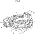
- FIG. 1 is a perspective view illustrating an external appearance of the rotary connector in the first embodiment of the present invention.
- FIG. 2 is a disassembled perspective view of important parts of the rotary connector.
- a rotary connector 1 is a connecting apparatus for transmitting electrical signals between a steering column (illustration omitted) and a steering shaft (illustration omitted) of a vehicle.
- the rotary connector 1 includes an annular rotor 2, and an annular stator 3.
- the rotor 2 is made of a synthetic resin, and a steering shaft contained in a steering column is inserted through a center part of the rotor 2.
- the stator 3 is made of a synthetic resin, and the rotor 2 that is mounted on the steering column is rotatably assembled on the stator 3.
- An annular space part (illustration omitted) is formed by a combination of the rotor 2 and the stator 3 within a main body of the rotary connector 1.
- a first main flexible printed circuit (hereinafter referred to as a first main FPC) 4 and a second main flexible printed circuit (hereinafter referred to as a second main FPC) 5 for securing electrical connection between the rotor 2 and the stator 3 are overlapped, wound, and coiled within this annular space part.
- first sub FPC 6 first flexible printed circuit
- rotor-side lead blocks 7 respectively having a plurality of external connection terminals 7A.
- the rotor-side lead blocks 7 are assembled into rotor-side connector parts 2B that are provided on an upper flange part 2A, via lead block insertion holes (illustration omitted) that are formed to open at an upper flange part 2A of the rotor 2.
- connector parts of external cables that are not illustrated may fit into the rotor-side connector parts 2B, to connect the external connection terminals 7A provided on the rotor 2 and connection terminals of the external cables. Hence, a load on the external connection terminals A may be reduced.
- FIG. 4 another end part 4B of the first main FPC 4 and another end part 5B of the second main FPC 5 are mounted on a second sub flexible printed circuit (hereinafter referred to as a second sub FPC) 8.
- the second sub FPC 8 is mounted on stator-side lead blocks 9 having a plurality of external connection terminals 9A.
- stator-side lead blocks 9 are assembled into stator-side connector parts 3B that are provided on an outer periphery of a tubular part 3A of the stator 3, via lead block insertion holes (illustration omitted) that are formed to open at the tubular part 3A of the stator 3.
- the first main FPC 4 is heat resistant, and is formed by a pair of insulating films 41 and 41 that are made of polyimide or the like having transparency, and sandwiching a plurality of band-shaped conductors 40 made of a copper film or the like and arranged in parallel along a width direction.
- the band-shaped conductors 40 are formed by etching during a process of manufacturing the first main FPC 4 using photolithography.
- the band-shaped conductors 40 are formed at a very fine pitch.
- the first main FPC 4 is formed to an elongated sheet having a length of approximately 50 cm, and having opposing side edges that are linear and parallel to each other.
- the first main FPC 4 is accommodated within the annular space part and is slidable in the wound and coiled state. By accommodating the first main FPC 4 within the annular space part in the wound and coiled state, it becomes possible to wind or unwind the first main FPC 4, to tolerate a rotation operation of a steering wheel (illustration omitted).
- connection terminals 10 made of a metal and connected to the band-shaped conductors 40 are arranged in parallel at the one end part 4A of the first main FPC 4.
- a part of the pair of insulating films 41 and 41 on the rear side of the insulating films 41 is removed to expose the connection terminals 10.
- the second main FPC 5 is heat resistant, and is formed by a pair of insulating films 41 and 41 that are made of polyimide or the like having transparency, and sandwiching a plurality of band-shaped conductors 40 made of a copper film, or the like and arranged in parallel along a width direction.
- the band-shaped conductors 40 are formed by etching during a process of manufacturing the second main FPC 5 using photolithography.
- the band-shaped conductors 40 are formed at a very fine pitch.
- the second main FPC 5 is formed to an elongated sheet having a length of approximately 50 cm, and having opposing side edges that are linear and parallel to each other.
- the second main FPC 5 is accommodated within the annular space part and is slidable in the wound and coiled state.
- connection terminals 11 made of a metal and connected to the band-shaped conductors 40 are arranged in parallel at the one end part 5A of the second main FPC 5.
- a part of the pair of insulating films 41 and 41 on the rear side of the insulating films 41 is removed to expose the connection terminals 11.
- the first sub FPC 6 is arranged to project in a direction perpendicular to a circumferential direction of each of the main FPCs 4 and 5.
- the one end parts 4A and 5A of the main FPCs 4 and 5 are butted against each other on a first wiring part 6A of the first sub FPC 6, and each of the main FPCs 4 and 5 is mounted on the first wiring part 6A so that longitudinal directions of of the main FPCs 4 and 5 become linear.
- the first sub FPC 6 is heat resistant, and is formed by a pair of insulating films 14 and 14 that are made of polyimide or the like having transparency, and sandwiching a plurality of band-shaped conductors 15 made of a copper film or the like and arranged in parallel along a width direction.
- the first sub FPC 6 is formed by the first wiring part 6A on which each of the one end parts 4A and 5A of the main FPCs 4 and 5 is mounted, a second wiring part 6B on which the rotor-side lead blocks 7 are mounted, and a third wiring part 6C connecting the first wiring part 6A and the second wiring part 6B.
- a plurality of connection terminals 16, that connect to the connection terminals 10 and 11 provided on each of the one end parts 4A and 5A of the main FPCs 4 and 5, are arranged in parallel on the first wiring part 6A.
- a plurality of connection terminals 17, that connect to the external connection terminals 7A of the rotor-side lead blocks 7, are arranged in parallel on the second wiring part 6B.
- a plurality of conductors (illustration omitted), that connect between the connection terminals 16 and 17 of the wiring parts 6A and 6B, are arranged on the third wiring part 6C.
- the plurality of conductors of the third wiring layer 6C are sandwiched and covered by the pair of insulating films 14 and 14.
- the rotary connector 1 includes a first holding member 18 for positioning and holding each of the one end parts 4A and 5A of the main FPCs 4 and 5, and the first sub FPC 6.
- the first holding member 18 is mounted on an outer periphery of a tubular part 2C of the rotor 2.
- the first holding member 18 is made of a synthetic resin, and is formed to a block body having an L-shape.
- the first holding member 18 includes a first holding part 18A for positioning and holding the first wiring part 6A of the first sub FPC 6 and each of the one end parts 4A and 5A of the main FPCs 4 and 5.
- a first holding part 18A for positioning and holding the first wiring part 6A of the first sub FPC 6 and each of the one end parts 4A and 5A of the main FPCs 4 and 5.
- each of the FPCs 4 and 5 is accommodated within the annular space part in a state in which each of the main FPCs 4 and 5 is standing in the width direction. Accordingly, each of the main FPCs 4 and 5 can smoothly slide within the annular space part.
- the first holding member 18 includes a second holding part 18B for holding the second wiring part 6B of the first sub FPC 6.
- the rotor-side lead blocks 7 are placed on the second holding part 18B, and the connection terminals 17 of the second wiring part 6B and the connection terminals 7A of the rotor-side lead blocks 7 are connected.
- the first holding member 18 includes a third holding part 18C for holding the third wiring part 6C of the first sub FPC 6.
- hook parts 20 and 20, that are locked by mounting parts (illustration omitted) formed on the upper flange part 2A of the rotor 2 are formed on the second holding part 18B of the first holding member 18.
- the first sub FPC 6 is arranged on the first holding member 18 so that the connection terminals 16 formed on the first wiring part 6A of the first sub FPC 6 face the front-side.
- the first wiring part 6A is pushed against the first holding part 18A, while the positioning caulking pins 21 formed on the first holding part 18A are inserted into the pin insertion holes 22 formed in the first wiring part 6A of the first sub FPC 6. As a result, the first wiring part 6A is positioned at a predetermined position on the first holding part 18A.
- the one end parts 4A and 5A of the main FPCs 4 and 5 are arranged on the first wiring part 6A, so that the surface where the connection terminals 10 and 11 of the one end parts 4A and 5A of the main FPCs 4 and 5 are exposed faces a rear-side.
- each of the connection terminals 10 and 11 and each of the connection terminals 16 of the first wiring part 6A are made to overlap via a solder.
- tip ends of the positioning caulking pins 21, projecting from the surface of each of the one end parts 4A and 5A of the main FPCs 4 and 5 are caulked.
- each of the one end parts 4A and 5A of the main FPCs 4 and 5 and the first wiring part 6A are overlapped on the first holding part 18A, and integrally positioned and held.
- each of the one end parts 4A and 5A of the main FPCs 4 and 5 is pushed against the outer periphery of the tubular part 2C of the rotor 2, together with the rotor-side lead blocks 7 that are connected by solder of a separate reflow process to the first sub FPC 6 on the second holding part 18B of the first holding member 18, to lock each of the hook parts 19 and 20 by the mounting parts provided on the rotor 2. Accordingly, by mounting the first holding member 18 on the outer periphery of the tubular part 2C of the rotor 2, it is possible to mount the one end parts 4A and 5A of the main FPCs 4 and 5 and the first sub FPC 6 at predetermined positions on the rotor 2.
- connection terminals 10 of the one end part 4A of the first main FPC and the connection terminals 11 of the one end part 5A of the second main FPC 5 have the same structure, the connection terminals 10 of the one end part 4A of the first main FPC 4 will be described, and a description of the connection terminals 11 of the one end part 5A of the second main FPC 5 will be omitted.
- connection terminals 10 of the one end part 4A of the first main FPC 4 and the connection terminals 16 of the first wiring part 6A are the same, a description of the connecting structure of the connection terminals 11 of the one end part 5A of the second main FPC 5 and the connection terminals 16 of the first wiring part 6A will be omitted.
- connection terminals 10 of the one end part 4A of the first main FPC 4 are formed to a U-shape having a pair of mutually opposing terminal pieces 10A and 10A, and and a slit part 10B is formed between the pair of terminal pieces 10A and 10A.
- a width W1 of the connection terminal 10 of the one end part 4A of the first main FPC 4 is formed narrower than a width W2 of the connection terminal 16 of the first wiring part 16A of the first sub FPC 6.
- connection terminals 10 of the one end part 4A of the first main FPC 4 and the connection terminals 16 of the first wiring part 6A are bonded by melting a solder 24 by a heater tool that is inserted from windows 23 and 23 formed in the first holding part 18A of the first holding member 18.
- the solder 24 between the terminals 10 and 16 is divided into two fillet shapes having bottom parts 24A and 24A that spread due to surface tension between the connection terminal 16 of the first wiring part 6A of the first sub FPC 6 and the terminal pieces 10A and 10A of the connection terminal 10 of the one end part 4A of the first main FPC.
- the adjacent bottom parts 24A and 24A are positioned by the slit part 10B.
- the slit part 10B of the connection terminal 10 of the one end part 4A of the first main FPC 4 can be observed visually or observed by a camera from the front-side (upper-side in FIG. 10 ) of the one end part 4A of the first main FPC 4 through the insulating film 41.
- the plurality of connection terminals 12 made of a metal and connected to the band-shaped conductors 40 are arranged in parallel at the other end part 4B of the first main FPC 4.
- the plurality of connection terminals 12 are mounted in an overlapping manner on a first wiring part 8A of the second sub FPC 8.
- the plurality of connection terminals 13 made of a metal and connected to the band-shaped conductors 40 are arranged in parallel at the other end part 5B of the second main FPC 5.
- the plurality of connection terminals 13 are mounted in an overlapping manner on a second wiring part 8B of the second sub FPC 8.
- the first wiring part 8A and the second wiring part 8B are provided in a continuous manner.
- the second sub FPC 8 is heat resistant, and is formed by a sheet-shaped insulating film 25 that is made of polyimide or the like having transparency, and a plurality of conductors 26 made of a copper film or the like and arranged in parallel on the insulating film 25.
- a third wiring part 8C and a fourth wiring part 8D to which the two stator-side lead blocks 9 are mounted, are provided on the second sub FPC 8.
- connection terminals 27 are arranged in parallel on the first wiring part 8A along the longitudinal directions of the main FPCs 4 and 5.
- a plurality of connection terminals 27 are also arranged in parallel on the second wiring part 8B along the longitudinal directions of the main FPCs 4 and 5.
- the rotary connector 1 includes a second holding member 28 for positioning and holding each of the other end parts 4B and 5B of the main FPCs 4 and 5, and the first wiring part 8A and the second wiring part 8B of the second sub FPC 8.
- the second holding member 28 is mounted on the outer periphery of the tubular part 3A of the stator 3.
- the second holding member 28 is made of a synthetic resin, and is formed to a plate shape.
- a plurality of positioning caulking pins 30 for positioning the wiring parts 8A and 8B of the second sub FPC 8 and the other end parts 4B and 5B of the main FPCs 4 and 5 that are mounted on the wiring parts 8A and 8B, are provided on a surface on which the first wiring part 8A and the second wiring part 8B of the second sub FPC 8 is mounted.
- a plurality of pin insertion holes 31 into which the positioning caulking pins 30 are inserted, are formed in the wiring parts 8A and 8B of the second sub FPC 8 and the other end parts 4B and 5B of each of the main FPCs 4 and 5.
- the second sub FPC 8 is arranged on the second holding member 28 so that the surface having the connection terminals 27 formed on the wiring parts 8A and 8B of the second sub FPC 8 faces the front-side.
- each of the wiring parts 8A and 8B is positioned at a predetermined position on the second holding member 28.
- the other end parts 4B and 5B of the main FPCs 4 and 5 are arranged on the wiring parts 8A and 8B, so that a surface where the connection terminals 12 and 13 of the other end parts 4B and 5B of the main FPCs 4 and 5 are exposed faces the rear-side (the side of each of the wiring parts 8A and 8B) .
- each of the connection terminals 12 and 13 and each of the connection terminals 27 of the wiring parts 8A and 8B are made to overlap via a solder.
- tip ends of the positioning caulking pins 30, projecting from the surface of each of the other end parts 4B and 5B of the main FPCs 4 and 5 are caulked.
- each of the other end parts 4B and 5B of the main FPCs 4 and 5 and the wiring parts 8A and 8B are overlapped on the second holding member 28, and integrally positioned and held.
- the other end parts 4B and 5B of the main FPCs 4 and 5 and the second sub FPC 8 can be mounted at predetermined positions on the stator 2.
- connection terminals 12 of the other end part 4B of the first main FPC 4 and the connection terminals 13 of the other end part 5B of the second main FPC 5 have the same structure. Hence, the connection terminals 12 of the other end part 4B of the first main FPC 4 will be described, and a description of the connection terminals 13 of the other end part 5B of the second main FPC 5 will be omitted.
- a connecting structure of the connection terminals 12 of the other end part 4B of the first main FPC 4 and the connection terminals 27 of the first wiring part 8A, and a connecting structure of the connection terminals 13 of the other end part 5B of the second main FPC 5 and the connection terminals 27 of the second wiring part 8B are the same.
- a connecting structure of the connection terminals 12 of the other end part 4B of the first main FPC 4 and the connection terminals 27 of the first wiring part, and a connecting structure of the connection terminals 10 of the one end part 4A of the first main FPC 4 and the connection terminals 16 of the first wiring part 6A are the same.
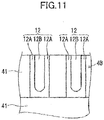
- FIG. 11 is a rear view of the connection terminals 12 of the other end part 4B of the first main FPC 4.
- the connection terminals 12 of the other end part 4B of the first main FPC 4 are formed to a U-shape having a pair of mutually opposing terminal pieces 12A and 12A, and and a slit part 12B is formed between the pair of terminal pieces 12A and 12A.
- connection terminals 12 of the other end part 4B of the first main FPC 4 and the connection terminals 27 of the first wiring part 8A of the second sub FPC 8 are bonded by melting a solder by a heater tool that is inserted from windows 32 and 32 formed in the second holding member 28, similarly to the above described bonding of the rotor-side connection terminals 12 and the connection terminals 16 of the first sub FPC 6.
- connection terminals of the other end part 4B of the first main FPC 4 and the connection terminals 27 of the second sub FPC 8 may be confirmed by observing whether bottom parts of the solder exist at the slit part 12B, similarly as in the case of the rotor-side connection terminals 10 described above. In other words, when the bottom parts of the solder exist at the slit part 12B, it may be confirmed that the connection terminals 12 and 27 are bonded by the solder, and thus enable positive bonding of the connection terminals 12 and 27 by a simple bonding operation.
- a flexible printed circuit that is sufficiently heat resistant and has an elongated shape with opposing side edges that are linear and parallel to each other may be used for each of the main FPCs 4 and 5.
- the main flexible printed circuits that are used may be arranged on a sheet base without a gap. For this reason, the number of main flexible printed circuits obtained (obtainable number) from the single sheet base can be made large, to reduce the unit price per each main flexible printed circuit. As a result, it is possible to provide an inexpensive rotary connector even when the flexible printed circuit is used as a wiring means.
- the one end parts 4A and 5A of the two main FPCs 4 and 5 can be mounted on the single first sub FPC 6, and the other end parts 4B and 5B of the two main FPCs 4 and 5 can be mounted on the single second sub FPC 8. For this reason, it is possible to reduce the number of parts, and reduce the cost of the parts.
- the first sub FPC 6 is mounted to project in a direction perpendicular to the circumferential direction of each of the main FPCs 4 and 5.
- the one end parts 4A and 5A of the main FPCs 4 and 5 are arranged to project in the direction perpendicular to the circumferential direction of each of the main FPCs 4 and 5, it is unnecessary to bend the one end parts 4A and 5A of the main FPCs 4 and 5 by 45 degrees, to facilitate a wiring operation on the FPC.
- the external connection terminals 7A can be mounted at accurate mounting positions.
- the second sub FPC 8 may have a structure such that the second sub FPC 8 is mounted in a direction perpendicular to the circumferential direction of each of the main FPCs 4 and 5.
- the second sub FPC of the present invention may be mounted obliquely to the circumferential direction of the main FPC, in a direction crossing the circumferential direction of the main FPC.
- the rotary connector 1 in this embodiment by caulking the positioning caulking pins 21 provided on the first holding part 18A of the first holding member 18, it is possible to integrally position and hold the one end parts 4A and 5A of the main FPCs 4 and 5 and the first wiring part 6A of the first sub FPC 6. As a result, the connection of the connection terminals 10 and the connection terminals 16 can be positively maintained, and the connection of the connection terminals 11 and the connection terminals 16 can be positively maintained.
- the soldered state (bonded state) of each connection terminal can be observed through the slit parts 10B and 12B formed in the connection terminals 10 and 12, to enable positive bonding of each connection terminal by a simple soldering operation.
- This embodiment describes an example in which the slit parts 10B and 12B are formed in the connection terminals 10 and 12 of the main FPCs 4 and 5.
- the present invention may be applied to a case in which the slit parts are formed in the connection terminals 16 and 27 of the first sub FPC 6 and the second sub FPC 8.
- the slit parts may be formed in either the connection terminals 10 and 12 of the main FPCs 4 and 5, or the connection terminals 16 and 27 of the first sub FPC 6 and the second sub FPC 8.
- solder is separately heated by the heater tool or by the reflow process or the like, in order to connect the connection terminals by the solder.
- any other suitable means may be used as long as the mechanical and electrical connection can be achieved after heating and cooling the solder.
- a rotary connector 50 in a second embodiment of the present invention will be described, by referring to FIG. 12 through FIG. 16 .
- a connecting structure of a first main FPC 51, a second main FPC 52, a first sub FPC 53, and a holding member 57 differs from the connecting structure of the rotary connector 1 in the first embodiment.
- a structure of the rotary connector 50, other than the connecting structure is basically the same as the structure of the rotary connector 1 in the first embodiment, and those parts that are the same are described using the same reference numerals.
- the connecting structure of the rotary connector 50 in this embodiment will be described in the following.
- FIG. 12 is a disassembled perspective view illustrating important parts of the rotary connector in the second embodiment of the present invention.
- FIG. 13 is a front view illustrating important parts in a mounted state of the main FPCs and the sub FPC of the rotary connector.
- FIG. 14 is a rear view illustrating the important parts in the mounted state of the main FPCs and the sub FPC of the rotary connector.
- the rotary connector 50 includes the first main FPC 51 and the second main FPC 52 for securing electrical connection between the rotor 2 and the stator 3.
- the first main FPC 51 and the second main FPC 52 are heat resistant, and are each formed by a pair of insulating films 61 and 61 that are made of polyimide or the like having transparency, and sandwiching a plurality of band-shaped conductors 60 made of a copper film or the like and arranged in parallel along a width direction.
- Each of the main FPCs 51 and 52 has a length of approximately 50 cm, and has opposing side edges that are linear and parallel to each other.
- the band-shaped conductors 60 are formed by etching during a process of manufacturing the main FPCs 51 and 52 using photolithography.
- the band-shaped conductors 60 are formed at a very fine pitch.
- the main FPCs 51 and 52 are overlapped, wound, and coiled within an annular space part formed in a main body of the rotary connector 50.
- the main FPCs 51 and 52 accommodated within the annular space part are slidable in the wound and coiled state.
- connection terminals 62 made of a metal and connected to the band-shaped conductors 60 are arranged in parallel on one end part 51A of the first main FPC 51.
- a part of the pair of insulating films 61 and 61 on the rear side of the insulating films 61 is removed to expose the connection terminals 62 of the one end part 51A of the first main FPC 51.
- connection terminals 63 made of a metal and connected to the band-shaped conductors 60 are arranged in parallel on one end part 52A of the second main FPC 52.
- a part of the pair of insulating films 61 and 61 on the rear side of the insulating films 61 is removed to expose the connection terminals 63 of the one end part 52A of the second main FPC 52.
- the first sub FPC 53 is arranged to project in a direction perpendicular to the circumferential direction of each of the main FPCs 51 and 52.
- the one end part 51A of the first main FPC 51 and the one end part 52A of the second main FPC 52 are butted against each other on a first wiring part 53A of the first sub FPC 53, which will be described later, and each of the main FPCs 51 and 52 is mounted on the first wiring part 53A so that longitudinal directions of of the main FPCs 51 and 52 become linear.
- the first sub FPC 53 is heat resistant, and is formed by a sheet-shaped insulating film 54 that is made of polyimide or the like having transparency, and a plurality of conductors 55 made of a copper film or the like and arranged in parallel on the insulating film 54.
- the sub FPC 53 is formed by a first wiring part 53A mounted on the one end parts 51A and 52A of the main FPCs 51 and 52, a second wiring part 53B mounted on a rotor-side lead block (illustration omitted), and a third wiring part 53C connecting the first wiring part 53A and the second wiring part 53B.
- a plurality of connection terminals 56 are arranged on the first wiring part 53A in parallel along a width direction.
- the rotary connector 50 includes the holding member 57 that positions and holds each of the one end parts 51A and 52A of the main FPCs 51 and 52 and the first FPC 53.
- the holding member 57 is made of a synthetic resin, and is formed to a plate shape.
- the one end parts 51A and 52A of the main FPCs 51 and 52 and the first wiring part 53A are mounted on the holding member 57 in the following manner.
- the holding member 57 is mounted on the outer periphery of the rotor 2.
- the one end parts 51A and 52A of the main FPCs 51 and 52 are arranged on the holding member 57 so that the surface where the connection terminals 62 and 63 of the one end parts 51A and 52A are exposed faces the front-side.
- the one end parts 51A and 52A are pushed against the holding member 57, while the positioning caulking pins 58 formed on the holding member 57 are inserted into the pin insertion holes 59 formed in the one end parts 51A and 52A. As a result, the one end parts 51A and 52A are positioned at predetermined positions on the holding member 57.
- the surface of the first wiring part 53A where the connection terminals 56 are exposed is arranged to face the rear-side (the side of each of the one end parts 51A and 52A of the main FPCs 51 and 52).
- the first wiring part 53A is pushed against each of the one end parts 51A and 52A, while inserting the positioning caulking pins 58 into the pin insertion holes 59 formed in the first wiring part 53A.
- each of the connection terminals 62 and 63 and each of the connection terminals 56 of the first wiring part 53 are made to overlap via a solder.
- tip ends of the positioning caulking pins 58, projecting from the surface of each of the one end parts 51A and 52A of the main FPCs 51 and 52 are caulked.
- each of the one end parts 51A and 52A of the main FPCs 51 and 52 and the first wiring part 53 are overlapped on the holding member 57, and integrally positioned and held.
- connection terminals 62 of the one end part 51A of the first main FPC and the connection terminals 63 of the one end part 52A of the second main FPC 52 have the same structure, the connection terminals 62 of the one end part 51A of the first main FPC 51 will be described, and a description of the connection terminals 63 of the one end part 52A of the second main FPC 52 will be omitted.
- connection terminals 62 of the one end part 51A of the first main FPC 51 and the connection terminals 56 of the first wiring part 53A and a connecting structure of the connection terminals 63 of the one end part 52A of the second main FPC 52 and the connection terminals 56 of the first wiring part 53A are the same, a description of the connecting structure of the connection terminals 63 of the one end part 52A of the second main FPC 52 and the connection terminals 56 of the first wiring part 53A will be omitted.
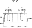
- connection terminals 62 of the one end part 51A of the first main FPC 51 are formed to a U-shape having a pair of mutually opposing terminal pieces 62A and 62A, and and a slit part 62B is formed between the pair of terminal pieces 62A and 62A.
- Observation windows 70 and 70 are formed in the holding member 57.
- connection terminals 62 of the one end part 51A of the first main FPC 51 and the connection terminals formed on the first wiring part 53A are bonded by melting the solder 24 by the heater tool that is inserted from the observation windows 70 and 70 formed in the rear-side of the holding member 57.
- the solder 24 between the connection terminals 62 and 56 is divided into two fillet shapes having the bottom parts 24A and 24A that spread due to surface tension between the connection terminal 56 of the first wiring part 53A and the terminal pieces 62A and 62A of the connection terminal 62 of the one end part 51A of the first main FPC 51.
- the adjacent bottom parts 24A and 24A are positioned by the slit part 62B.
- the slit part 62B of the connection terminal 62 of the one end part 51A of the first main FPC 51 can be observed visually or observed by a camera from the rear-side of the holding member 57 through the observation window 70. In other words, it is possible to observe whether the bottom parts 24A of the solder 24 exist at the slit part 62B. Accordingly, when the bottom parts 24A of the solder 24 exist at the slit part 62B, it is possible to confirm that the terminals 62 and 56 are bonded by the solder 24, to thereby enable positive bonding of the terminals 62 and 56 by a simple operation.
- Each of the other end parts 51B and 52B of the main FPCs 51 and 52 is mounted on the second sub FPC (illustration omitted).
- Each of the other end parts 51B and 52B and the second sub FPC are positioned and held by a holding member (illustration omitted).
- connection terminals 64 and 65 of the other end parts 51B and 52B of the main FPCs 51 and 52 are formed to a U-shape, similarly to the connection terminals 62 of the one end part 51A of the first main FPC 51. Further, the connection terminals 64 and 65 are bonded to connection terminals (illustration omitted) of the sub FPC (illustration omitted), similarly to the connection terminals 62 and 63 that are bonded to the connection terminals 56 of the first sub FPC 53.
- the observation window 70 is provided in the holding member 57, to observe the slit part 62B of the connection terminals 62 of the first main FPC 51.
- the soldered state of the connection terminals 62 of the one end part 51A of the first main FPC 51 and the connection terminals 56 of the first sub FPC 53 can be observed from the outside through the observation window 70, and it is possible to positively bond the connection terminals 62 and 56 by a simple bonding operation.
- the present invention is applicable to a rotary connector for transmitting electrical signals between an annular stator and a rotor that is rotatably assembled on the annular stator.
Landscapes
- Engineering & Computer Science (AREA)
- Microelectronics & Electronic Packaging (AREA)
- Mechanical Engineering (AREA)
- Coupling Device And Connection With Printed Circuit (AREA)
- Multi-Conductor Connections (AREA)
Abstract
Description
- The present invention relates to a rotary connector for transmitting electrical signals between a rotor and a stator on which the rotor is rotatably assembled, and more particularly to a rotary connector for transmitting electrical signals between a steering shaft and a steering column of a vehicle.
- A conventionally known rotary connector used in the vehicle, such as an automobile or the like, electrically connects an electric apparatus provided on a steering wheel and an electric apparatus provided on a vehicle body.
- The rotary connector includes a movable housing mounted on the steering shaft of the vehicle, a stationary housing mounted on the steering column so that the movable housing is rotatable, and a flat cable accommodated within an annular space part that is formed between the two housings and electrically connects external connection terminals provided on the two housings. This rotary connector is used as an electrical connecting means of the electric apparatus such as a horn circuit, an airbag system, various kinds of operation switches, or the like provided in the steering wheel of the vehicle.
- Patent Document 1 proposes a rotary connector using a plurality of flat cables for connecting the electric apparatuses described above.
-
- Patent Document 1: Japanese Laid-Open Patent Publication No.
2013-219007 - Patent Document 2: Japanese Laid-Open Patent Publication No.
2006-100733 - The flat cables proposed in Patent Document 1 have the following problems.
- In general, the flat cable in most cases uses polyester (PET) as an insulating film that covers band-shaped conductors. There is a problem in that the polyester has a low heat resistance. Accordingly, in distribution of goods using ships or the like, packaging of the flat cable is required so that the insulating film does not deteriorate due to environmental changes.
- In addition, because it is difficult to form the band-shaped conductors of the flat cable at a very fine pitch, a plurality of flat cables are required when the number of band-shaped conductors forming signal lines needs to be increased.
- In order to solve these problems, it is conceivable to use a flexible printed circuit that has an excellent heat resistance, in place of the flat cable. In many cases, a plurality of flexible printed circuits are arranged side by side on a single sheet base and stored, to improve handling of the flexible printed circuit when assembling the flexible printed circuit.
- As an example, Patent Document 2 proposes forming a large number of unit substrates on a sheet base. When delivering the unit substrates, the unit substrates are generally delivered in the state in which the unit substrates are formed on the sheet base. When using the unit substrates, the sheet base is divided into the unit substrates, to assemble the unit substrate into a product.
- However, in a case in which the unit substrate has a shape that is partially concavo-convex, such as an L-shape or a T-shape, a gap is formed between adjacent unit substrates when the unit substrates are arranged side by side on the sheet base. For this reason, the number of unit substrates that can be cut from the single sheet base decreases, to increase the cost of a FPC component forming the unit substrate, and as a result, make it difficult to reduce the cost of the rotary connector.
- The present invention is conceived in view of the above circumstances, and one object is to provide a rotary connector that has an excellent heat resistance, and is inexpensive even when a flexible printed wiring substrate on which band-shaped conductors can be formed at a very fine pitch is used as a connecting means of an electrical apparatus.
- In order to achieve the object described above, a rotary connector of the present invention is characterized in that there are provided a rotor; a stator rotatably assembled on the rotor; a main flexible printed circuit having two side edges that are linear and parallel to each other, and wound and coiled within an annular space part formed between the rotor and the stator; a first sub flexible printed circuit mounted on one end part of the main flexible printed circuit, and connecting a connection terminal provided on the one end part and an external connection terminal provided on the rotor; and a second sub flexible printed circuit mounted on another end part of the main flexible printed circuit, and connecting a connection terminal provided on the other end part and an external connection terminal provided on the stator.
- According to this structure, the main flexible printed circuits that are used may be arranged on a sheet base without a gap. For this reason, the number of main flexible printed circuits obtained (obtainable number) from the single sheet base can be made large, to reduce the unit price per each main flexible printed circuit.
- Preferably, the rotary connector of the present invention is characterized in that a plurality of main flexible printed circuits are provided, and both end parts of each of the plurality of main flexible printed circuits are mounted on the first sub flexible printed circuit and the second sub flexible printed circuit, respectively.
- According to this structure, each end part of the plurality of main flexible printed circuits can be connected to one sub flexible printed circuit, to reduce the number of parts. Accordingly, it is possible to reduce the cost of the parts.
- In addition, in the operation of connecting each main flexible printed circuit and the sub flexible printed circuit, it is possible to simultaneously set each main flexible printed circuit and the sub flexible printed circuit on a jig, to thereby improve the assembling efficiency.
- Preferably, the rotary connector of the present invention is characterized in that at least one of the first sub flexible printed circuit and the second sub flexible printed circuit is mounted to project in a direction crossing a circumferential direction of the main flexible printed circuit.
- According to this structure, in a case in which the end part of the main flexible printed circuit is arranged to project in the direction perpendicular to the circumferential direction of the main flexible printed circuit, it is unnecessary to bend the main flexible printed circuit by 45 degrees, to facilitate a wiring operation on the main flexible printed circuit.
- In addition, because it is unnecessary to bend the main flexible printed circuit, there is no inconsistency or the like in the bent position of the main flexible printed circuit, and external terminals can be mounted at accurate mounting positions.
- Preferably, the rotary connector of the present invention is characterized in that the main flexible printed circuit, the first sub flexible printed circuit, and the second sub flexible printed circuit are overlapped on a first holding member and a second holding member that are provided with positioning caulking pins, to integrally position and hold the main flexible printed circuit, the first sub flexible printed circuit, and the second sub flexible printed circuit on the first holding member and the second holding member.
- According to this structure, a positive connection of the connection terminal of the main flexible printed circuit and the connection terminal of the sub flexible printed circuit can be maintained.
- Preferably, the rotary connector of the present invention is characterized in that a connection terminal of the main flexible printed circuit is connected to a connection terminal provided on each of the first sub flexible printed circuit and the second sub flexible printed circuit, and a slit part is formed in one of the connection terminal of the main flexible printed circuit and the connection terminal of each of the first sub flexible printed circuit and the second sub flexible printed circuit.
- According to this structure, the slit part formed in the connection terminal enables observation of a soldered state of each connection terminal, to positively bond each connection terminal by a simple soldering operation.
- Preferably, the rotary connector of the present invention is characterized in that an observation window is provided in each of the first holding member and the second holding member to observe the slit part from outside.
- According to this structure, the soldered state of each connection terminal can be observed from the outside through the observation window, to enable positive bonding of each connection terminal by a simple soldering operation.
- Preferably, in the rotary connector of the present invention, the external connection terminal provided on the rotor is fixed on a rotor-side lead block, and the rotor-side lead block is fixed on a rotor-side connector part of the rotor.
- According to this structure, a connector part of an external cable may be fitted to the rotor-side connector part, to connect the external connection terminal provided on the rotor to a connection terminal of an external cable. Hence, a load on the external connection terminal can be reduced.
- According to the present invention, it is possible to provide a rotary connector that has an excellent heat resistance, and is inexpensive even when a flexible printed wiring substrate on which band-shaped conductors can be formed at a very fine pitch is used as a connecting means of an electrical apparatus.
-
-
FIG. 1 is a perspective view illustrating an external appearance of a rotary connector in a first embodiment of the present invention; -
FIG. 2 is a disassembled perspective view of important parts of the rotary connector; -
FIG. 3 is an enlarged perspective view illustrating a connection state of a main flexible printed circuit and a first sub flexible printed circuit; -
FIG. 4 is an enlarged disassembled perspective view illustrating a connection state of the main flexible printed circuit and a second sub flexible printed circuit; -
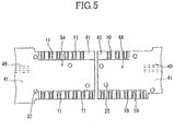
FIG. 5 is a rear view illustrating an end part of the main flexible printed circuit; -
FIG. 6 is an enlarged front view illustrating the first sub flexible printed circuit; -
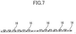
FIG. 7 is a cross sectional view along a line VII-VII inFIG. 6 ; -
FIG. 8 is an enlarged perspective view illustrating a first holding member; -
FIG. 9 is an enlarged front view for explaining a bonded state between connection terminals on one end part of the main flexible printed circuit and the first sub flexible printed circuit; -
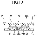
FIG. 10 is a cross sectional view along a line X-X inFIG. 9 ; -
FIG. 11 is an enlarged rear view for explaining connection terminals on another end part of the main flexible printed circuit; -
FIG. 12 is a disassembled perspective view illustrating important parts of the rotary connector in a second embodiment of the present invention; -
FIG. 13 is a front view illustrating important parts in a mounted state of the main flexible printed circuits and the sub flexible printed circuit; -
FIG. 14 is a rear view illustrating the important parts in the mounted state of the main flexible printed circuits and the sub flexible printed circuit; -
FIG. 15 is an enlarged rear view for explaining connection terminals on one end part of the main flexible printed circuit; and -
FIG. 16 is a schematic view for explaining a bonded state of the connection terminals on the one end part of the main flexible printed circuit. - A rotary connector in a first embodiment of the present invention will be described.
-
FIG. 1 is a perspective view illustrating an external appearance of the rotary connector in the first embodiment of the present invention.FIG. 2 is a disassembled perspective view of important parts of the rotary connector. - A rotary connector 1 is a connecting apparatus for transmitting electrical signals between a steering column (illustration omitted) and a steering shaft (illustration omitted) of a vehicle.
- As illustrated in
FIG. 1 andFIG. 2 , the rotary connector 1 includes an annular rotor 2, and anannular stator 3. The rotor 2 is made of a synthetic resin, and a steering shaft contained in a steering column is inserted through a center part of the rotor 2. Thestator 3 is made of a synthetic resin, and the rotor 2 that is mounted on the steering column is rotatably assembled on thestator 3. - An annular space part (illustration omitted) is formed by a combination of the rotor 2 and the
stator 3 within a main body of the rotary connector 1. A first main flexible printed circuit (hereinafter referred to as a first main FPC) 4 and a second main flexible printed circuit (hereinafter referred to as a second main FPC) 5 for securing electrical connection between the rotor 2 and thestator 3 are overlapped, wound, and coiled within this annular space part. - As illustrated in
FIG. 3 , oneend part 4A of the firstmain FPC 4 and oneend part 5A of the secondmain FPC 5 are mounted on a first flexible printed circuit (hereinafter referred to as a first sub FPC) 6. Thefirst sub FPC 6 is mounted on rotor-side lead blocks 7 respectively having a plurality ofexternal connection terminals 7A. - The rotor-side lead blocks 7 are assembled into rotor-
side connector parts 2B that are provided on anupper flange part 2A, via lead block insertion holes (illustration omitted) that are formed to open at anupper flange part 2A of the rotor 2. - According to this structure, connector parts of external cables that are not illustrated may fit into the rotor-
side connector parts 2B, to connect theexternal connection terminals 7A provided on the rotor 2 and connection terminals of the external cables. Hence, a load on the external connection terminals A may be reduced. - As illustrated in
FIG. 4 , anotherend part 4B of the firstmain FPC 4 and anotherend part 5B of the secondmain FPC 5 are mounted on a second sub flexible printed circuit (hereinafter referred to as a second sub FPC) 8. Thesecond sub FPC 8 is mounted on stator-side lead blocks 9 having a plurality ofexternal connection terminals 9A. - The stator-side lead blocks 9 are assembled into stator-
side connector parts 3B that are provided on an outer periphery of atubular part 3A of thestator 3, via lead block insertion holes (illustration omitted) that are formed to open at thetubular part 3A of thestator 3. - The first
main FPC 4 is heat resistant, and is formed by a pair of insulatingfilms conductors 40 made of a copper film or the like and arranged in parallel along a width direction. The band-shapedconductors 40 are formed by etching during a process of manufacturing the firstmain FPC 4 using photolithography. The band-shapedconductors 40 are formed at a very fine pitch. - The first
main FPC 4 is formed to an elongated sheet having a length of approximately 50 cm, and having opposing side edges that are linear and parallel to each other. The firstmain FPC 4 is accommodated within the annular space part and is slidable in the wound and coiled state. By accommodating the firstmain FPC 4 within the annular space part in the wound and coiled state, it becomes possible to wind or unwind the firstmain FPC 4, to tolerate a rotation operation of a steering wheel (illustration omitted). - As illustrated in
FIG. 5 , a plurality ofconnection terminals 10 made of a metal and connected to the band-shapedconductors 40 are arranged in parallel at the oneend part 4A of the firstmain FPC 4. At the oneend part 4A of the firstmain FPC 4, a part of the pair of insulatingfilms films 41 is removed to expose theconnection terminals 10. - Similarly as in the case of the first
main FPC 4, the secondmain FPC 5 is heat resistant, and is formed by a pair of insulatingfilms conductors 40 made of a copper film, or the like and arranged in parallel along a width direction. The band-shapedconductors 40 are formed by etching during a process of manufacturing the secondmain FPC 5 using photolithography. The band-shapedconductors 40 are formed at a very fine pitch. - Similarly as in the case of the first
main FPC 4, the secondmain FPC 5 is formed to an elongated sheet having a length of approximately 50 cm, and having opposing side edges that are linear and parallel to each other. The secondmain FPC 5 is accommodated within the annular space part and is slidable in the wound and coiled state. By accommodating the secondmain FPC 5 within the annular space part in the wound and coiled state, it becomes possible to wind or unwind the secondmain FPC 5, to tolerate the rotation operation of the steering wheel (illustration omitted). - As illustrated in
FIG. 5 , a plurality ofconnection terminals 11 made of a metal and connected to the band-shapedconductors 40 are arranged in parallel at the oneend part 5A of the secondmain FPC 5. At the oneend part 5A of the secondmain FPC 5, a part of the pair of insulatingfilms films 41 is removed to expose theconnection terminals 11. - As illustrated in
FIG. 3 , thefirst sub FPC 6 is arranged to project in a direction perpendicular to a circumferential direction of each of themain FPCs end parts main FPCs first wiring part 6A of thefirst sub FPC 6, and each of themain FPCs first wiring part 6A so that longitudinal directions of of themain FPCs - As illustrated in
FIG. 6 andFIG. 7 , thefirst sub FPC 6 is heat resistant, and is formed by a pair of insulatingfilms conductors 15 made of a copper film or the like and arranged in parallel along a width direction. - The
first sub FPC 6 is formed by thefirst wiring part 6A on which each of the oneend parts main FPCs second wiring part 6B on which the rotor-side lead blocks 7 are mounted, and athird wiring part 6C connecting thefirst wiring part 6A and thesecond wiring part 6B. - A plurality of
connection terminals 16, that connect to theconnection terminals end parts main FPCs first wiring part 6A. A plurality ofconnection terminals 17, that connect to theexternal connection terminals 7A of the rotor-side lead blocks 7, are arranged in parallel on thesecond wiring part 6B. A plurality of conductors (illustration omitted), that connect between theconnection terminals wiring parts third wiring part 6C. The plurality of conductors of thethird wiring layer 6C are sandwiched and covered by the pair of insulatingfilms - The rotary connector 1 includes a first holding
member 18 for positioning and holding each of the oneend parts main FPCs first sub FPC 6. The first holdingmember 18 is mounted on an outer periphery of a tubular part 2C of the rotor 2. The first holdingmember 18 is made of a synthetic resin, and is formed to a block body having an L-shape. - As illustrated in
FIG. 8 , the first holdingmember 18 includes a first holding part 18A for positioning and holding thefirst wiring part 6A of thefirst sub FPC 6 and each of the oneend parts main FPCs end parts main FPCs connection terminals 16 of thefirst wiring part 6A and theconnection terminals end parts main FPCs - In addition, because each of the one
end parts main FPCs FPCs main FPCs main FPCs - The first holding
member 18 includes asecond holding part 18B for holding thesecond wiring part 6B of thefirst sub FPC 6. The rotor-side lead blocks 7 are placed on thesecond holding part 18B, and theconnection terminals 17 of thesecond wiring part 6B and theconnection terminals 7A of the rotor-side lead blocks 7 are connected. - The first holding
member 18 includes athird holding part 18C for holding thethird wiring part 6C of thefirst sub FPC 6. - A
hook part 19, that is locked by a mounting part (illustration omitted) formed on the tubular part 2C of the rotor 2, is formed on the first holding part 18A of the first holdingmember 18. In addition,hook parts upper flange part 2A of the rotor 2, are formed on thesecond holding part 18B of the first holdingmember 18. - In the first holding part 18A of the first holding
member 18, a plurality of positioning caulking pins 21 for positioning thefirst wiring part 6A and the oneend parts main FPCs first wiring part 6A, are provided on a surface on which thefirst wiring part 6A of thefirst sub FPC 6 is mounted. A plurality of pin insertion holes 22 into which the positioning caulking pins 21 are inserted, are formed in thefirst wiring part 6A of thefirst sub FPC 6 and the oneend parts main FPCs - Next, a method of mounting the one
end parts main FPCs first sub FPC 6, and the first holdingmember 18 will be described. - First, the
first sub FPC 6 is arranged on the first holdingmember 18 so that theconnection terminals 16 formed on thefirst wiring part 6A of thefirst sub FPC 6 face the front-side. - Then, the
first wiring part 6A is pushed against the first holding part 18A, while the positioning caulking pins 21 formed on the first holding part 18A are inserted into the pin insertion holes 22 formed in thefirst wiring part 6A of thefirst sub FPC 6. As a result, thefirst wiring part 6A is positioned at a predetermined position on the first holding part 18A. - Next, the one
end parts main FPCs first wiring part 6A, so that the surface where theconnection terminals end parts main FPCs - Then, the one
end parts main FPCs first wiring part 6A, while the positioning caulking pins 21 are inserted into the pin insertion holes 22 formed in the oneend parts main FPCs connection terminals connection terminals 16 of thefirst wiring part 6A are made to overlap via a solder. - Next, tip ends of the positioning caulking pins 21, projecting from the surface of each of the one
end parts main FPCs - Accordingly, each of the one
end parts main FPCs first wiring part 6A are overlapped on the first holding part 18A, and integrally positioned and held. - Next, the surface of each of the one
end parts main FPCs first sub FPC 6 on thesecond holding part 18B of the first holdingmember 18, to lock each of thehook parts member 18 on the outer periphery of the tubular part 2C of the rotor 2, it is possible to mount the oneend parts main FPCs first sub FPC 6 at predetermined positions on the rotor 2. - Because the
connection terminals 10 of the oneend part 4A of the first main FPC and theconnection terminals 11 of the oneend part 5A of the secondmain FPC 5 have the same structure, theconnection terminals 10 of the oneend part 4A of the firstmain FPC 4 will be described, and a description of theconnection terminals 11 of the oneend part 5A of the secondmain FPC 5 will be omitted. In addition, because a connecting structure of theconnection terminals 10 of the oneend part 4A of the firstmain FPC 4 and theconnection terminals 16 of thefirst wiring part 6A, and a connecting structure of theconnection terminals 11 of the oneend part 5A of the secondmain FPC 5 and theconnection terminals 16 of thefirst wiring part 6A are the same, a description of the connecting structure of theconnection terminals 11 of the oneend part 5A of the secondmain FPC 5 and theconnection terminals 16 of thefirst wiring part 6A will be omitted. - As illustrated in
FIG. 5 andFIG. 9 , theconnection terminals 10 of the oneend part 4A of the firstmain FPC 4 are formed to a U-shape having a pair of mutually opposingterminal pieces slit part 10B is formed between the pair ofterminal pieces connection terminal 10 of the oneend part 4A of the firstmain FPC 4 is formed narrower than a width W2 of theconnection terminal 16 of the first wiring part 16A of thefirst sub FPC 6. - The
connection terminals 10 of the oneend part 4A of the firstmain FPC 4 and theconnection terminals 16 of thefirst wiring part 6A are bonded by melting asolder 24 by a heater tool that is inserted fromwindows member 18. - As illustrated in
FIG. 10 , thesolder 24 between theterminals bottom parts connection terminal 16 of thefirst wiring part 6A of thefirst sub FPC 6 and theterminal pieces connection terminal 10 of the oneend part 4A of the first main FPC. In addition, at thesolder 24, the adjacentbottom parts slit part 10B. Theslit part 10B of theconnection terminal 10 of the oneend part 4A of the firstmain FPC 4 can be observed visually or observed by a camera from the front-side (upper-side inFIG. 10 ) of the oneend part 4A of the firstmain FPC 4 through the insulatingfilm 41. In other words, it is possible to observe whether thebottom parts solder 24 exist at theslit part 10B. Accordingly, when thebottom parts solder 24 exist at theslit part 10B, it is possible to confirm that theterminals solder 24, to thereby enable positive bonding of theterminals - As illustrated in
FIG. 4 , the plurality ofconnection terminals 12 made of a metal and connected to the band-shapedconductors 40 are arranged in parallel at theother end part 4B of the firstmain FPC 4. The plurality ofconnection terminals 12 are mounted in an overlapping manner on afirst wiring part 8A of thesecond sub FPC 8. In addition, the plurality ofconnection terminals 13 made of a metal and connected to the band-shapedconductors 40 are arranged in parallel at theother end part 5B of the secondmain FPC 5. The plurality ofconnection terminals 13 are mounted in an overlapping manner on asecond wiring part 8B of thesecond sub FPC 8. Thefirst wiring part 8A and thesecond wiring part 8B are provided in a continuous manner. - The
second sub FPC 8 is heat resistant, and is formed by a sheet-shaped insulatingfilm 25 that is made of polyimide or the like having transparency, and a plurality ofconductors 26 made of a copper film or the like and arranged in parallel on the insulatingfilm 25. - A
third wiring part 8C and afourth wiring part 8D to which the two stator-side lead blocks 9 are mounted, are provided on thesecond sub FPC 8. - A plurality of
connection terminals 27 are arranged in parallel on thefirst wiring part 8A along the longitudinal directions of themain FPCs connection terminals 27 are also arranged in parallel on thesecond wiring part 8B along the longitudinal directions of themain FPCs - The rotary connector 1 includes a second holding
member 28 for positioning and holding each of theother end parts main FPCs first wiring part 8A and thesecond wiring part 8B of thesecond sub FPC 8. The second holdingmember 28 is mounted on the outer periphery of thetubular part 3A of thestator 3. The second holdingmember 28 is made of a synthetic resin, and is formed to a plate shape. - In the second holding
member 28, a plurality of positioning caulking pins 30 for positioning thewiring parts second sub FPC 8 and theother end parts main FPCs wiring parts first wiring part 8A and thesecond wiring part 8B of thesecond sub FPC 8 is mounted. A plurality of pin insertion holes 31 into which the positioning caulking pins 30 are inserted, are formed in thewiring parts second sub FPC 8 and theother end parts main FPCs - Next, a method of mounting each of the
other end parts main FPCs second sub FPC 8, and the second holdingmember 28 will be described. - First, the
second sub FPC 8 is arranged on the second holdingmember 28 so that the surface having theconnection terminals 27 formed on thewiring parts second sub FPC 8 faces the front-side. - Then, the
wiring parts member 28, while inserting the positioning caulking pins 30 formed on the second holdingmember 28 are inserted into the pin insertion holes 31 formed in thewiring parts second sub FPC 8. As a result, each of thewiring parts member 28. - Next, the
other end parts main FPCs wiring parts connection terminals other end parts main FPCs wiring parts - Then, the
other end parts main FPCs wiring parts other end parts main FPCs connection terminals connection terminals 27 of thewiring parts - Next, tip ends of the positioning caulking pins 30, projecting from the surface of each of the
other end parts main FPCs - Accordingly, each of the
other end parts main FPCs wiring parts member 28, and integrally positioned and held. - Next, by mounting the second holding
member 28 on the outer periphery of thetubular part 3A of thestator 3, theother end parts main FPCs second sub FPC 8 can be mounted at predetermined positions on the stator 2. - The
connection terminals 12 of theother end part 4B of the firstmain FPC 4 and theconnection terminals 13 of theother end part 5B of the secondmain FPC 5 have the same structure. Hence, theconnection terminals 12 of theother end part 4B of the firstmain FPC 4 will be described, and a description of theconnection terminals 13 of theother end part 5B of the secondmain FPC 5 will be omitted. - In addition, a connecting structure of the
connection terminals 12 of theother end part 4B of the firstmain FPC 4 and theconnection terminals 27 of thefirst wiring part 8A, and a connecting structure of theconnection terminals 13 of theother end part 5B of the secondmain FPC 5 and theconnection terminals 27 of thesecond wiring part 8B are the same. Further, a connecting structure of theconnection terminals 12 of theother end part 4B of the firstmain FPC 4 and theconnection terminals 27 of the first wiring part, and a connecting structure of theconnection terminals 10 of the oneend part 4A of the firstmain FPC 4 and theconnection terminals 16 of thefirst wiring part 6A are the same. Hence, a detailed description of the connecting structure of theconnection terminals connection terminals -
FIG. 11 is a rear view of theconnection terminals 12 of theother end part 4B of the firstmain FPC 4. Theconnection terminals 12 of theother end part 4B of the firstmain FPC 4 are formed to a U-shape having a pair of mutually opposingterminal pieces slit part 12B is formed between the pair ofterminal pieces - The
connection terminals 12 of theother end part 4B of the firstmain FPC 4 and theconnection terminals 27 of thefirst wiring part 8A of thesecond sub FPC 8 are bonded by melting a solder by a heater tool that is inserted fromwindows member 28, similarly to the above described bonding of the rotor-side connection terminals 12 and theconnection terminals 16 of thefirst sub FPC 6. - The bonded state of the connection terminals of the
other end part 4B of the firstmain FPC 4 and theconnection terminals 27 of thesecond sub FPC 8 may be confirmed by observing whether bottom parts of the solder exist at theslit part 12B, similarly as in the case of the rotor-side connection terminals 10 described above. In other words, when the bottom parts of the solder exist at theslit part 12B, it may be confirmed that theconnection terminals connection terminals - Hence, according to the rotary connector 1 in this embodiment, a flexible printed circuit that is sufficiently heat resistant and has an elongated shape with opposing side edges that are linear and parallel to each other may be used for each of the
main FPCs - In addition, according to the rotary connector 1 in this embodiment, the one
end parts main FPCs first sub FPC 6, and theother end parts main FPCs second sub FPC 8. For this reason, it is possible to reduce the number of parts, and reduce the cost of the parts. - Further, in the operation of connecting the
main FPCs sub FPCs main FPCs sub FPCs - In this embodiment, a description is given of an example in which two
main FPCs - In addition, according to the rotary connector 1 in this embodiment, the
first sub FPC 6 is mounted to project in a direction perpendicular to the circumferential direction of each of themain FPCs end parts main FPCs main FPCs end parts main FPCs main FPCs main FPCs external connection terminals 7A can be mounted at accurate mounting positions. - In the present invention, the
second sub FPC 8 may have a structure such that thesecond sub FPC 8 is mounted in a direction perpendicular to the circumferential direction of each of themain FPCs - Further, although this embodiment describes an example in which the
first sub FPC 6 is arranged in a direction perpendicular to the circumferential direction of each of themain FPCs - In addition, according to the rotary connector 1 in this embodiment, by caulking the positioning caulking pins 21 provided on the first holding part 18A of the first holding
member 18, it is possible to integrally position and hold the oneend parts main FPCs first wiring part 6A of thefirst sub FPC 6. As a result, the connection of theconnection terminals 10 and theconnection terminals 16 can be positively maintained, and the connection of theconnection terminals 11 and theconnection terminals 16 can be positively maintained. - Further, according to the rotary connector 1 in this embodiment, the soldered state (bonded state) of each connection terminal can be observed through the
slit parts connection terminals - This embodiment describes an example in which the
slit parts connection terminals main FPCs connection terminals first sub FPC 6 and thesecond sub FPC 8. In other words, the slit parts may be formed in either theconnection terminals main FPCs connection terminals first sub FPC 6 and thesecond sub FPC 8. - In addition, the solder is separately heated by the heater tool or by the reflow process or the like, in order to connect the connection terminals by the solder. However, any other suitable means may be used as long as the mechanical and electrical connection can be achieved after heating and cooling the solder.
- A
rotary connector 50 in a second embodiment of the present invention will be described, by referring toFIG. 12 through FIG. 16 . In therotary connector 50 in this embodiment, a connecting structure of a firstmain FPC 51, a secondmain FPC 52, afirst sub FPC 53, and a holdingmember 57 differs from the connecting structure of the rotary connector 1 in the first embodiment. A structure of therotary connector 50, other than the connecting structure, is basically the same as the structure of the rotary connector 1 in the first embodiment, and those parts that are the same are described using the same reference numerals. The connecting structure of therotary connector 50 in this embodiment will be described in the following. -
FIG. 12 is a disassembled perspective view illustrating important parts of the rotary connector in the second embodiment of the present invention.FIG. 13 is a front view illustrating important parts in a mounted state of the main FPCs and the sub FPC of the rotary connector.FIG. 14 is a rear view illustrating the important parts in the mounted state of the main FPCs and the sub FPC of the rotary connector. - The
rotary connector 50 includes the firstmain FPC 51 and the secondmain FPC 52 for securing electrical connection between the rotor 2 and thestator 3. - The first
main FPC 51 and the secondmain FPC 52 are heat resistant, and are each formed by a pair of insulatingfilms conductors 60 made of a copper film or the like and arranged in parallel along a width direction. Each of themain FPCs - The band-shaped
conductors 60 are formed by etching during a process of manufacturing themain FPCs conductors 60 are formed at a very fine pitch. - The
main FPCs rotary connector 50. Themain FPCs - A plurality of
connection terminals 62 made of a metal and connected to the band-shapedconductors 60 are arranged in parallel on oneend part 51A of the firstmain FPC 51. In the oneend part 51A of the firstmain FPC 51, a part of the pair of insulatingfilms films 61 is removed to expose theconnection terminals 62 of the oneend part 51A of the firstmain FPC 51. - A plurality of
connection terminals 63 made of a metal and connected to the band-shapedconductors 60 are arranged in parallel on oneend part 52A of the secondmain FPC 52. In the oneend part 52A of the secondmain FPC 52, a part of the pair of insulatingfilms films 61 is removed to expose theconnection terminals 63 of the oneend part 52A of the secondmain FPC 52. - The
first sub FPC 53 is arranged to project in a direction perpendicular to the circumferential direction of each of themain FPCs end part 51A of the firstmain FPC 51 and the oneend part 52A of the secondmain FPC 52 are butted against each other on afirst wiring part 53A of thefirst sub FPC 53, which will be described later, and each of themain FPCs first wiring part 53A so that longitudinal directions of of themain FPCs - The
first sub FPC 53 is heat resistant, and is formed by a sheet-shaped insulatingfilm 54 that is made of polyimide or the like having transparency, and a plurality ofconductors 55 made of a copper film or the like and arranged in parallel on the insulatingfilm 54. - The
sub FPC 53 is formed by afirst wiring part 53A mounted on the oneend parts main FPCs second wiring part 53B mounted on a rotor-side lead block (illustration omitted), and athird wiring part 53C connecting thefirst wiring part 53A and thesecond wiring part 53B. A plurality ofconnection terminals 56 are arranged on thefirst wiring part 53A in parallel along a width direction. - The
rotary connector 50 includes the holdingmember 57 that positions and holds each of the oneend parts main FPCs first FPC 53. The holdingmember 57 is made of a synthetic resin, and is formed to a plate shape. - In the holding
part 57, a plurality of positioning caulking pins 58 for positioning and fixing each of the oneend parts first wiring part 53A of thefirst sub FPC 53, are provided on a surface on which the oneend parts main FPCs connection terminal parts first wiring part 53A. - The one
end parts main FPCs first wiring part 53A are mounted on the holdingmember 57 in the following manner. The holdingmember 57 is mounted on the outer periphery of the rotor 2. - First, the one
end parts main FPCs member 57 so that the surface where theconnection terminals end parts - Next, the one
end parts member 57, while the positioning caulking pins 58 formed on the holdingmember 57 are inserted into the pin insertion holes 59 formed in the oneend parts end parts member 57. - Then, the surface of the
first wiring part 53A where theconnection terminals 56 are exposed is arranged to face the rear-side (the side of each of the oneend parts main FPCs 51 and 52). Next, thefirst wiring part 53A is pushed against each of the oneend parts first wiring part 53A. In this state, each of theconnection terminals connection terminals 56 of thefirst wiring part 53 are made to overlap via a solder. - Next, tip ends of the positioning caulking pins 58, projecting from the surface of each of the one
end parts main FPCs - Accordingly, each of the one
end parts main FPCs first wiring part 53 are overlapped on the holdingmember 57, and integrally positioned and held. - Because the
connection terminals 62 of the oneend part 51A of the first main FPC and theconnection terminals 63 of the oneend part 52A of the secondmain FPC 52 have the same structure, theconnection terminals 62 of the oneend part 51A of the firstmain FPC 51 will be described, and a description of theconnection terminals 63 of the oneend part 52A of the secondmain FPC 52 will be omitted. - In addition, because a connecting structure of the
connection terminals 62 of the oneend part 51A of the firstmain FPC 51 and theconnection terminals 56 of thefirst wiring part 53A, and a connecting structure of theconnection terminals 63 of the oneend part 52A of the secondmain FPC 52 and theconnection terminals 56 of thefirst wiring part 53A are the same, a description of the connecting structure of theconnection terminals 63 of the oneend part 52A of the secondmain FPC 52 and theconnection terminals 56 of thefirst wiring part 53A will be omitted. - As illustrated in
FIG. 15 , theconnection terminals 62 of the oneend part 51A of the firstmain FPC 51 are formed to a U-shape having a pair of mutually opposingterminal pieces slit part 62B is formed between the pair ofterminal pieces Observation windows member 57. - The
connection terminals 62 of the oneend part 51A of the firstmain FPC 51 and the connection terminals formed on thefirst wiring part 53A are bonded by melting thesolder 24 by the heater tool that is inserted from theobservation windows member 57. - As illustrated in
FIG. 16 , thesolder 24 between theconnection terminals bottom parts connection terminal 56 of thefirst wiring part 53A and theterminal pieces connection terminal 62 of the oneend part 51A of the firstmain FPC 51. In addition, at thesolder 24, the adjacentbottom parts slit part 62B. - The
slit part 62B of theconnection terminal 62 of the oneend part 51A of the firstmain FPC 51 can be observed visually or observed by a camera from the rear-side of the holdingmember 57 through theobservation window 70. In other words, it is possible to observe whether thebottom parts 24A of thesolder 24 exist at theslit part 62B. Accordingly, when thebottom parts 24A of thesolder 24 exist at theslit part 62B, it is possible to confirm that theterminals solder 24, to thereby enable positive bonding of theterminals - Each of the
other end parts main FPCs other end parts - In addition,
connection terminals other end parts main FPCs connection terminals 62 of the oneend part 51A of the firstmain FPC 51. Further, theconnection terminals connection terminals connection terminals 56 of thefirst sub FPC 53. - According to the
rotary connector 50 in the second embodiment, theobservation window 70 is provided in the holdingmember 57, to observe theslit part 62B of theconnection terminals 62 of the firstmain FPC 51. Hence, the soldered state of theconnection terminals 62 of the oneend part 51A of the firstmain FPC 51 and theconnection terminals 56 of thefirst sub FPC 53 can be observed from the outside through theobservation window 70, and it is possible to positively bond theconnection terminals - The present invention is not limited to the embodiments described above. In other words, it is apparent to those skilled in the art that various variations, combinations, sub-combinations, and substitutions may be made to the structures of the embodiments described above without departing from the scope of the present invention.
- The present invention is applicable to a rotary connector for transmitting electrical signals between an annular stator and a rotor that is rotatably assembled on the annular stator.
-
- 1, 50 Rotary connector
- 2 Rotor
- 2B Rotor-side connector part
- 3 Stator
- 3B Stator-side connector part
- 4, 51 First main FPC
- 5, 52 Second main FPC
- 6 First sub FPC
- 8 Second sub FPC
- 53 First sub FPC
- 7 Rotor-side lead block
- 9 Stator-side lead block
- 7A, 9A External connection terminal
- 10, 11, 12, 13 Connection terminal
- 16, 27, 56 Connection terminal
- 56 Connection terminal
- 62, 63, 64, 65 Connection terminal
- 10B, 12B, 62B Slit part
- 18 First holding member
- 28 Second holding member
- 57 Holding member
- 21, 30, 58 Positioning caulking pin
- 22, 31, 59 Pin insertion hole
- 70 Observation window
Claims (7)
- A rotary connector characterized in that there are provided:a rotor;a stator rotatably assembled on the rotor;a main flexible printed circuit having two side edges that are linear and parallel to each other, and wound and coiled within an annular space part formed between the rotor and the stator;a first sub flexible printed circuit mounted on one end part of the main flexible printed circuit, and connecting a connection terminal provided on the one end part and an external connection terminal provided on the rotor; anda second sub flexible printed circuit mounted on another end part of the main flexible printed circuit, and connecting a connection terminal provided on the other end part and an external connection terminal provided on the stator.
- The rotary connector as claimed in claim 1, characterized in that a plurality of main flexible printed circuits are provided, and both end parts of each of the plurality of main flexible printed circuits are mounted on the first sub flexible printed circuit and the second sub flexible printed circuit, respectively.
- The rotary connector as claimed in claim 1 or 2, characterized in that at least one of the first sub flexible printed circuit and the second sub flexible printed circuit is mounted to project in a direction crossing a circumferential direction of the main flexible printed circuit.
- The rotary connector as claimed in any of claims 1 to 3, characterized in that the main flexible printed circuit, the first sub flexible printed circuit, and the second sub flexible printed circuit are overlapped on a first holding member and a second holding member that are provided with positioning caulking pins, to integrally position and hold the main flexible printed circuit, the first sub flexible printed circuit, and the second sub flexible printed circuit on the first holding member and the second holding member.
- The rotary connector as claimed in any of claims 1 to 4, characterized in that a connection terminal of the main flexible printed circuit is connected to a connection terminal provided on each of the first sub flexible printed circuit and the second sub flexible printed circuit, and a slit part is formed in one of the connection terminal of the main flexible printed circuit and the connection terminal of each of the first sub flexible printed circuit and the second sub flexible printed circuit.
- The rotary connector as claimed in any one of claims 1 to 5, characterized in that an observation window is provided in each of the first holding member and the second holding member to observe the slit part from outside.
- The rotary connector as claimed in any of claims 1 to 6, wherein
the external connection terminal provided on the rotor is fixed on a rotor-side lead block, and
the rotor-side lead block is fixed on a rotor-side connector part of the rotor.
Applications Claiming Priority (2)
| Application Number | Priority Date | Filing Date | Title |
|---|---|---|---|
| JP2016108706 | 2016-05-31 | ||
| PCT/JP2017/007748 WO2017208544A1 (en) | 2016-05-31 | 2017-02-28 | Rotary connector |
Publications (3)
| Publication Number | Publication Date |
|---|---|
| EP3467967A1 true EP3467967A1 (en) | 2019-04-10 |
| EP3467967A4 EP3467967A4 (en) | 2020-01-29 |
| EP3467967B1 EP3467967B1 (en) | 2021-11-24 |
Family
ID=60479276
Family Applications (1)
| Application Number | Title | Priority Date | Filing Date |
|---|---|---|---|
| EP17806106.5A Active EP3467967B1 (en) | 2016-05-31 | 2017-02-28 | Rotary connector |
Country Status (5)
| Country | Link |
|---|---|
| US (1) | US10468845B2 (en) |
| EP (1) | EP3467967B1 (en) |
| JP (1) | JP6735344B2 (en) |
| CN (1) | CN109075517B (en) |
| WO (1) | WO2017208544A1 (en) |
Families Citing this family (8)
| Publication number | Priority date | Publication date | Assignee | Title |
|---|---|---|---|---|
| EP3467966B1 (en) * | 2016-05-31 | 2021-08-18 | Alps Alpine Co., Ltd. | Rotary connector |
| DE102017222999B4 (en) * | 2017-12-18 | 2021-10-21 | Robert Bosch Gmbh | Sensor device for a steering system of a vehicle |
| JP6944403B2 (en) * | 2018-03-20 | 2021-10-06 | アルプスアルパイン株式会社 | Rotating connector |
| KR102689415B1 (en) * | 2018-05-28 | 2024-07-29 | 후루카와 덴키 고교 가부시키가이샤 | Rotating connector device and rotating body of the rotating connector device |
| EP3930117B1 (en) * | 2019-02-21 | 2024-06-05 | Furukawa Electric Co., Ltd. | Rotary connector device |
| WO2022196286A1 (en) * | 2021-03-15 | 2022-09-22 | アルプスアルパイン株式会社 | Rotary connector |
| WO2023140310A1 (en) | 2022-01-21 | 2023-07-27 | 古河電気工業株式会社 | Rotary connector device |
| WO2024053462A1 (en) | 2022-09-07 | 2024-03-14 | 古河電気工業株式会社 | Rotational connector device and on-board device |
Family Cites Families (25)
| Publication number | Priority date | Publication date | Assignee | Title |
|---|---|---|---|---|
| JPS63137069U (en) * | 1987-02-27 | 1988-09-08 | ||
| JPH0745923A (en) * | 1993-05-24 | 1995-02-14 | Ibiden Co Ltd | Flexible printed wiring board and composite board |
| JPH09134748A (en) * | 1995-11-09 | 1997-05-20 | Yazaki Corp | Cable connection structure |
| JP3416413B2 (en) * | 1996-08-19 | 2003-06-16 | アルプス電気株式会社 | Rotating connector |
| DE59700996D1 (en) * | 1996-11-25 | 2000-02-17 | Contraves Ag | Line connection |
| JP2000133399A (en) * | 1998-10-27 | 2000-05-12 | Harness Syst Tech Res Ltd | Rotary connection device and terminal welding method suitable for its manufacture |
| JP3522148B2 (en) * | 1999-04-23 | 2004-04-26 | アルプス電気株式会社 | Rotating connector |
| USH1991H1 (en) * | 1999-07-01 | 2001-09-04 | Methode Electronics, Inc. | Clockspring using flexible printed wiring |
| JP4716541B2 (en) * | 2000-04-14 | 2011-07-06 | ナイルス株式会社 | Rotating connector device |
| DE60237410D1 (en) * | 2001-02-21 | 2010-10-07 | Alps Electric Co Ltd | Rotary connector with multiple flexible cables |
| JP4024025B2 (en) * | 2001-10-11 | 2007-12-19 | ナイルス株式会社 | Rotating connector device |
| US6854977B2 (en) * | 2002-09-13 | 2005-02-15 | Trw Inc. | Steering wheel rotary connector |
| US6780032B2 (en) * | 2002-10-07 | 2004-08-24 | Tyco Electronics Corporation | Loop back clockspring connector having high current capacity |
| US6962497B2 (en) * | 2003-04-16 | 2005-11-08 | The Furukawa Electric Co., Ltd. | Rotary connector having an identifiable neutral position |
| US7104821B2 (en) * | 2004-09-16 | 2006-09-12 | Alps Electric Co., Ltd. | Rotary connector |
| JP2006100733A (en) * | 2004-09-30 | 2006-04-13 | Nippon Mektron Ltd | Flexible board |
| JP2006120512A (en) * | 2004-10-22 | 2006-05-11 | Alps Electric Co Ltd | Rotary connector |
| EP1981131A1 (en) * | 2007-04-14 | 2008-10-15 | Delphi Technologies, Inc. | Electrical connection device |
| JP5123070B2 (en) * | 2008-06-19 | 2013-01-16 | ナイルス株式会社 | Rotating connector device |
| JP5117528B2 (en) * | 2010-03-30 | 2013-01-16 | 古河電気工業株式会社 | Rotating connector device |
| JP5117529B2 (en) * | 2010-03-30 | 2013-01-16 | 古河電気工業株式会社 | Rotating connector device |
| KR101322593B1 (en) * | 2011-03-14 | 2013-10-28 | 알프스 덴키 가부시키가이샤 | Rotary connector |
| CN103378526B (en) * | 2012-04-11 | 2015-05-27 | 阿尔卑斯电气株式会社 | Rotation connector |
| JP5886148B2 (en) * | 2012-06-21 | 2016-03-16 | 株式会社ヴァレオジャパン | Rotating connector device |
| JP6293088B2 (en) * | 2015-05-11 | 2018-03-14 | アルプス電気株式会社 | Manufacturing method of rotating connector |
-
2017
- 2017-02-28 JP JP2018520661A patent/JP6735344B2/en active Active
- 2017-02-28 CN CN201780026988.0A patent/CN109075517B/en active Active
- 2017-02-28 WO PCT/JP2017/007748 patent/WO2017208544A1/en not_active Ceased
- 2017-02-28 EP EP17806106.5A patent/EP3467967B1/en active Active
-
2018
- 2018-10-30 US US16/174,833 patent/US10468845B2/en active Active
Also Published As
| Publication number | Publication date |
|---|---|
| EP3467967B1 (en) | 2021-11-24 |
| CN109075517A (en) | 2018-12-21 |
| WO2017208544A1 (en) | 2017-12-07 |
| EP3467967A4 (en) | 2020-01-29 |
| CN109075517B (en) | 2020-05-05 |
| JPWO2017208544A1 (en) | 2019-02-28 |
| US10468845B2 (en) | 2019-11-05 |
| US20190067892A1 (en) | 2019-02-28 |
| JP6735344B2 (en) | 2020-08-05 |
Similar Documents
| Publication | Publication Date | Title |
|---|---|---|
| EP3467967B1 (en) | Rotary connector | |
| US10651617B1 (en) | Rotary connector and method for assembling same | |
| JP5080134B2 (en) | Terminal mounting structure | |
| EP1157892B1 (en) | Wire harness joint | |
| US10554003B2 (en) | Rotary connector | |
| JP5128228B2 (en) | Flat cable connection end structure | |
| WO2011132570A1 (en) | Connection structure for a wiring material | |
| JP2013219007A (en) | Rotary connector | |
| JP4001788B2 (en) | Circuit assembly and electrical junction box | |
| JP4240105B2 (en) | Multi-core coaxial cable and manufacturing method thereof | |
| WO2021075165A1 (en) | Wiring module | |
| US6469261B2 (en) | Wiring unit | |
| JP5018564B2 (en) | Multi-layer FFC connection structure | |
| JP6975053B2 (en) | Terminal connection structure, flexible board, and rotary connector | |
| JP2003235128A (en) | Electrical junction box | |
| JPS6180712A (en) | Concentrated circuit boards for wire harnesses and automotive wire harnesses | |
| JP6815502B2 (en) | Rotating connector | |
| JPH07245130A (en) | Joint box for flat cable | |
| JP2003203699A (en) | Flexible flat cable connector connection structure | |
| JP2021068695A (en) | Wiring module | |
| JP2003032844A (en) | Connecting method and configuration of flexible flat cable | |
| JP2000197250A (en) | Wire-harness joint structure | |
| JP2013191392A (en) | Terminal material |
Legal Events
| Date | Code | Title | Description |
|---|---|---|---|
| STAA | Information on the status of an ep patent application or granted ep patent |
Free format text: STATUS: THE INTERNATIONAL PUBLICATION HAS BEEN MADE |
|
| PUAI | Public reference made under article 153(3) epc to a published international application that has entered the european phase |
Free format text: ORIGINAL CODE: 0009012 |
|
| STAA | Information on the status of an ep patent application or granted ep patent |
Free format text: STATUS: REQUEST FOR EXAMINATION WAS MADE |
|
| 17P | Request for examination filed |
Effective date: 20181115 |
|
| AK | Designated contracting states |
Kind code of ref document: A1 Designated state(s): AL AT BE BG CH CY CZ DE DK EE ES FI FR GB GR HR HU IE IS IT LI LT LU LV MC MK MT NL NO PL PT RO RS SE SI SK SM TR |
|
| AX | Request for extension of the european patent |
Extension state: BA ME |
|
| DAV | Request for validation of the european patent (deleted) | ||
| DAX | Request for extension of the european patent (deleted) | ||
| REG | Reference to a national code |
Ref country code: DE Ref legal event code: R079 Ref document number: 602017049891 Country of ref document: DE Free format text: PREVIOUS MAIN CLASS: H01R0035040000 Ipc: B60R0016027000 |
|
| A4 | Supplementary search report drawn up and despatched |
Effective date: 20200108 |
|
| RIC1 | Information provided on ipc code assigned before grant |
Ipc: H01R 35/04 20060101ALI20191220BHEP Ipc: B60R 16/027 20060101AFI20191220BHEP |
|
| STAA | Information on the status of an ep patent application or granted ep patent |
Free format text: STATUS: EXAMINATION IS IN PROGRESS |
|
| 17Q | First examination report despatched |
Effective date: 20200821 |
|
| GRAP | Despatch of communication of intention to grant a patent |
Free format text: ORIGINAL CODE: EPIDOSNIGR1 |
|
| STAA | Information on the status of an ep patent application or granted ep patent |
Free format text: STATUS: GRANT OF PATENT IS INTENDED |
|
| INTG | Intention to grant announced |
Effective date: 20210624 |
|
| GRAS | Grant fee paid |
Free format text: ORIGINAL CODE: EPIDOSNIGR3 |
|
| GRAA | (expected) grant |
Free format text: ORIGINAL CODE: 0009210 |
|
| STAA | Information on the status of an ep patent application or granted ep patent |
Free format text: STATUS: THE PATENT HAS BEEN GRANTED |
|
| AK | Designated contracting states |
Kind code of ref document: B1 Designated state(s): AL AT BE BG CH CY CZ DE DK EE ES FI FR GB GR HR HU IE IS IT LI LT LU LV MC MK MT NL NO PL PT RO RS SE SI SK SM TR |
|
| REG | Reference to a national code |
Ref country code: GB Ref legal event code: FG4D |
|
| REG | Reference to a national code |
Ref country code: AT Ref legal event code: REF Ref document number: 1449644 Country of ref document: AT Kind code of ref document: T Effective date: 20211215 |
|
| REG | Reference to a national code |
Ref country code: DE Ref legal event code: R096 Ref document number: 602017049891 Country of ref document: DE |
|
| REG | Reference to a national code |
Ref country code: IE Ref legal event code: FG4D |
|
| REG | Reference to a national code |
Ref country code: LT Ref legal event code: MG9D |
|
| REG | Reference to a national code |
Ref country code: NL Ref legal event code: MP Effective date: 20211124 |
|
| REG | Reference to a national code |
Ref country code: AT Ref legal event code: MK05 Ref document number: 1449644 Country of ref document: AT Kind code of ref document: T Effective date: 20211124 |
|
| PG25 | Lapsed in a contracting state [announced via postgrant information from national office to epo] |
Ref country code: RS Free format text: LAPSE BECAUSE OF FAILURE TO SUBMIT A TRANSLATION OF THE DESCRIPTION OR TO PAY THE FEE WITHIN THE PRESCRIBED TIME-LIMIT Effective date: 20211124 Ref country code: LT Free format text: LAPSE BECAUSE OF FAILURE TO SUBMIT A TRANSLATION OF THE DESCRIPTION OR TO PAY THE FEE WITHIN THE PRESCRIBED TIME-LIMIT Effective date: 20211124 Ref country code: FI Free format text: LAPSE BECAUSE OF FAILURE TO SUBMIT A TRANSLATION OF THE DESCRIPTION OR TO PAY THE FEE WITHIN THE PRESCRIBED TIME-LIMIT Effective date: 20211124 Ref country code: BG Free format text: LAPSE BECAUSE OF FAILURE TO SUBMIT A TRANSLATION OF THE DESCRIPTION OR TO PAY THE FEE WITHIN THE PRESCRIBED TIME-LIMIT Effective date: 20220224 Ref country code: AT Free format text: LAPSE BECAUSE OF FAILURE TO SUBMIT A TRANSLATION OF THE DESCRIPTION OR TO PAY THE FEE WITHIN THE PRESCRIBED TIME-LIMIT Effective date: 20211124 |
|
| PG25 | Lapsed in a contracting state [announced via postgrant information from national office to epo] |
Ref country code: IS Free format text: LAPSE BECAUSE OF FAILURE TO SUBMIT A TRANSLATION OF THE DESCRIPTION OR TO PAY THE FEE WITHIN THE PRESCRIBED TIME-LIMIT Effective date: 20220324 Ref country code: SE Free format text: LAPSE BECAUSE OF FAILURE TO SUBMIT A TRANSLATION OF THE DESCRIPTION OR TO PAY THE FEE WITHIN THE PRESCRIBED TIME-LIMIT Effective date: 20211124 Ref country code: PT Free format text: LAPSE BECAUSE OF FAILURE TO SUBMIT A TRANSLATION OF THE DESCRIPTION OR TO PAY THE FEE WITHIN THE PRESCRIBED TIME-LIMIT Effective date: 20220324 Ref country code: PL Free format text: LAPSE BECAUSE OF FAILURE TO SUBMIT A TRANSLATION OF THE DESCRIPTION OR TO PAY THE FEE WITHIN THE PRESCRIBED TIME-LIMIT Effective date: 20211124 Ref country code: NO Free format text: LAPSE BECAUSE OF FAILURE TO SUBMIT A TRANSLATION OF THE DESCRIPTION OR TO PAY THE FEE WITHIN THE PRESCRIBED TIME-LIMIT Effective date: 20220224 Ref country code: NL Free format text: LAPSE BECAUSE OF FAILURE TO SUBMIT A TRANSLATION OF THE DESCRIPTION OR TO PAY THE FEE WITHIN THE PRESCRIBED TIME-LIMIT Effective date: 20211124 Ref country code: LV Free format text: LAPSE BECAUSE OF FAILURE TO SUBMIT A TRANSLATION OF THE DESCRIPTION OR TO PAY THE FEE WITHIN THE PRESCRIBED TIME-LIMIT Effective date: 20211124 Ref country code: HR Free format text: LAPSE BECAUSE OF FAILURE TO SUBMIT A TRANSLATION OF THE DESCRIPTION OR TO PAY THE FEE WITHIN THE PRESCRIBED TIME-LIMIT Effective date: 20211124 Ref country code: GR Free format text: LAPSE BECAUSE OF FAILURE TO SUBMIT A TRANSLATION OF THE DESCRIPTION OR TO PAY THE FEE WITHIN THE PRESCRIBED TIME-LIMIT Effective date: 20220225 Ref country code: ES Free format text: LAPSE BECAUSE OF FAILURE TO SUBMIT A TRANSLATION OF THE DESCRIPTION OR TO PAY THE FEE WITHIN THE PRESCRIBED TIME-LIMIT Effective date: 20211124 |
|
| PG25 | Lapsed in a contracting state [announced via postgrant information from national office to epo] |
Ref country code: SM Free format text: LAPSE BECAUSE OF FAILURE TO SUBMIT A TRANSLATION OF THE DESCRIPTION OR TO PAY THE FEE WITHIN THE PRESCRIBED TIME-LIMIT Effective date: 20211124 Ref country code: SK Free format text: LAPSE BECAUSE OF FAILURE TO SUBMIT A TRANSLATION OF THE DESCRIPTION OR TO PAY THE FEE WITHIN THE PRESCRIBED TIME-LIMIT Effective date: 20211124 Ref country code: RO Free format text: LAPSE BECAUSE OF FAILURE TO SUBMIT A TRANSLATION OF THE DESCRIPTION OR TO PAY THE FEE WITHIN THE PRESCRIBED TIME-LIMIT Effective date: 20211124 Ref country code: EE Free format text: LAPSE BECAUSE OF FAILURE TO SUBMIT A TRANSLATION OF THE DESCRIPTION OR TO PAY THE FEE WITHIN THE PRESCRIBED TIME-LIMIT Effective date: 20211124 Ref country code: DK Free format text: LAPSE BECAUSE OF FAILURE TO SUBMIT A TRANSLATION OF THE DESCRIPTION OR TO PAY THE FEE WITHIN THE PRESCRIBED TIME-LIMIT Effective date: 20211124 Ref country code: CZ Free format text: LAPSE BECAUSE OF FAILURE TO SUBMIT A TRANSLATION OF THE DESCRIPTION OR TO PAY THE FEE WITHIN THE PRESCRIBED TIME-LIMIT Effective date: 20211124 |
|
| REG | Reference to a national code |
Ref country code: DE Ref legal event code: R097 Ref document number: 602017049891 Country of ref document: DE |
|
| PG25 | Lapsed in a contracting state [announced via postgrant information from national office to epo] |
Ref country code: MC Free format text: LAPSE BECAUSE OF FAILURE TO SUBMIT A TRANSLATION OF THE DESCRIPTION OR TO PAY THE FEE WITHIN THE PRESCRIBED TIME-LIMIT Effective date: 20211124 |
|
| PLBE | No opposition filed within time limit |
Free format text: ORIGINAL CODE: 0009261 |
|
| STAA | Information on the status of an ep patent application or granted ep patent |
Free format text: STATUS: NO OPPOSITION FILED WITHIN TIME LIMIT |
|
| REG | Reference to a national code |
Ref country code: CH Ref legal event code: PL |
|
| REG | Reference to a national code |
Ref country code: BE Ref legal event code: MM Effective date: 20220228 |
|
| GBPC | Gb: european patent ceased through non-payment of renewal fee |
Effective date: 20220228 |
|
| PG25 | Lapsed in a contracting state [announced via postgrant information from national office to epo] |
Ref country code: LU Free format text: LAPSE BECAUSE OF NON-PAYMENT OF DUE FEES Effective date: 20220228 Ref country code: AL Free format text: LAPSE BECAUSE OF FAILURE TO SUBMIT A TRANSLATION OF THE DESCRIPTION OR TO PAY THE FEE WITHIN THE PRESCRIBED TIME-LIMIT Effective date: 20211124 |
|
| 26N | No opposition filed |
Effective date: 20220825 |
|
| PG25 | Lapsed in a contracting state [announced via postgrant information from national office to epo] |
Ref country code: SI Free format text: LAPSE BECAUSE OF FAILURE TO SUBMIT A TRANSLATION OF THE DESCRIPTION OR TO PAY THE FEE WITHIN THE PRESCRIBED TIME-LIMIT Effective date: 20211124 |
|
| PG25 | Lapsed in a contracting state [announced via postgrant information from national office to epo] |
Ref country code: LI Free format text: LAPSE BECAUSE OF NON-PAYMENT OF DUE FEES Effective date: 20220228 Ref country code: IE Free format text: LAPSE BECAUSE OF NON-PAYMENT OF DUE FEES Effective date: 20220228 Ref country code: GB Free format text: LAPSE BECAUSE OF NON-PAYMENT OF DUE FEES Effective date: 20220228 Ref country code: CH Free format text: LAPSE BECAUSE OF NON-PAYMENT OF DUE FEES Effective date: 20220228 |
|
| PG25 | Lapsed in a contracting state [announced via postgrant information from national office to epo] |
Ref country code: BE Free format text: LAPSE BECAUSE OF NON-PAYMENT OF DUE FEES Effective date: 20220228 |
|
| PG25 | Lapsed in a contracting state [announced via postgrant information from national office to epo] |
Ref country code: IT Free format text: LAPSE BECAUSE OF FAILURE TO SUBMIT A TRANSLATION OF THE DESCRIPTION OR TO PAY THE FEE WITHIN THE PRESCRIBED TIME-LIMIT Effective date: 20211124 |
|
| PG25 | Lapsed in a contracting state [announced via postgrant information from national office to epo] |
Ref country code: HU Free format text: LAPSE BECAUSE OF FAILURE TO SUBMIT A TRANSLATION OF THE DESCRIPTION OR TO PAY THE FEE WITHIN THE PRESCRIBED TIME-LIMIT; INVALID AB INITIO Effective date: 20170228 |
|
| PG25 | Lapsed in a contracting state [announced via postgrant information from national office to epo] |
Ref country code: MK Free format text: LAPSE BECAUSE OF FAILURE TO SUBMIT A TRANSLATION OF THE DESCRIPTION OR TO PAY THE FEE WITHIN THE PRESCRIBED TIME-LIMIT Effective date: 20211124 Ref country code: CY Free format text: LAPSE BECAUSE OF FAILURE TO SUBMIT A TRANSLATION OF THE DESCRIPTION OR TO PAY THE FEE WITHIN THE PRESCRIBED TIME-LIMIT Effective date: 20211124 |
|
| PG25 | Lapsed in a contracting state [announced via postgrant information from national office to epo] |
Ref country code: MT Free format text: LAPSE BECAUSE OF FAILURE TO SUBMIT A TRANSLATION OF THE DESCRIPTION OR TO PAY THE FEE WITHIN THE PRESCRIBED TIME-LIMIT Effective date: 20211124 |
|
| PG25 | Lapsed in a contracting state [announced via postgrant information from national office to epo] |
Ref country code: TR Free format text: LAPSE BECAUSE OF FAILURE TO SUBMIT A TRANSLATION OF THE DESCRIPTION OR TO PAY THE FEE WITHIN THE PRESCRIBED TIME-LIMIT Effective date: 20211124 |
|
| PGFP | Annual fee paid to national office [announced via postgrant information from national office to epo] |
Ref country code: DE Payment date: 20260218 Year of fee payment: 10 |
|
| PGFP | Annual fee paid to national office [announced via postgrant information from national office to epo] |
Ref country code: FR Payment date: 20260218 Year of fee payment: 10 |