EP3467903A1 - Battery pack - Google Patents
Battery pack Download PDFInfo
- Publication number
- EP3467903A1 EP3467903A1 EP18770779.9A EP18770779A EP3467903A1 EP 3467903 A1 EP3467903 A1 EP 3467903A1 EP 18770779 A EP18770779 A EP 18770779A EP 3467903 A1 EP3467903 A1 EP 3467903A1
- Authority
- EP
- European Patent Office
- Prior art keywords
- battery
- insert
- battery pack
- battery modules
- connection member
- Prior art date
- Legal status (The legal status is an assumption and is not a legal conclusion. Google has not performed a legal analysis and makes no representation as to the accuracy of the status listed.)
- Granted
Links
- 239000002356 single layer Substances 0.000 claims description 5
- WHXSMMKQMYFTQS-UHFFFAOYSA-N Lithium Chemical compound [Li] WHXSMMKQMYFTQS-UHFFFAOYSA-N 0.000 description 6
- 229910052744 lithium Inorganic materials 0.000 description 6
- 230000000694 effects Effects 0.000 description 4
- 239000007773 negative electrode material Substances 0.000 description 4
- 239000007774 positive electrode material Substances 0.000 description 4
- 230000008878 coupling Effects 0.000 description 3
- 238000010168 coupling process Methods 0.000 description 3
- 238000005859 coupling reaction Methods 0.000 description 3
- 230000006870 function Effects 0.000 description 3
- HBBGRARXTFLTSG-UHFFFAOYSA-N Lithium ion Chemical compound [Li+] HBBGRARXTFLTSG-UHFFFAOYSA-N 0.000 description 2
- PXHVJJICTQNCMI-UHFFFAOYSA-N Nickel Chemical compound [Ni] PXHVJJICTQNCMI-UHFFFAOYSA-N 0.000 description 2
- 230000005611 electricity Effects 0.000 description 2
- 229910001416 lithium ion Inorganic materials 0.000 description 2
- 239000000463 material Substances 0.000 description 2
- 238000012986 modification Methods 0.000 description 2
- 230000004048 modification Effects 0.000 description 2
- 238000003466 welding Methods 0.000 description 2
- RYGMFSIKBFXOCR-UHFFFAOYSA-N Copper Chemical compound [Cu] RYGMFSIKBFXOCR-UHFFFAOYSA-N 0.000 description 1
- XAGFODPZIPBFFR-UHFFFAOYSA-N aluminium Chemical compound [Al] XAGFODPZIPBFFR-UHFFFAOYSA-N 0.000 description 1
- 229910052782 aluminium Inorganic materials 0.000 description 1
- 230000000712 assembly Effects 0.000 description 1
- 238000000429 assembly Methods 0.000 description 1
- OJIJEKBXJYRIBZ-UHFFFAOYSA-N cadmium nickel Chemical compound [Ni].[Cd] OJIJEKBXJYRIBZ-UHFFFAOYSA-N 0.000 description 1
- 239000003575 carbonaceous material Substances 0.000 description 1
- 229910052802 copper Inorganic materials 0.000 description 1
- 239000010949 copper Substances 0.000 description 1
- 238000007599 discharging Methods 0.000 description 1
- 238000001035 drying Methods 0.000 description 1
- 239000003792 electrolyte Substances 0.000 description 1
- 239000008151 electrolyte solution Substances 0.000 description 1
- 238000004146 energy storage Methods 0.000 description 1
- 238000005516 engineering process Methods 0.000 description 1
- 239000011888 foil Substances 0.000 description 1
- 230000017525 heat dissipation Effects 0.000 description 1
- GPRLSGONYQIRFK-UHFFFAOYSA-N hydron Chemical compound [H+] GPRLSGONYQIRFK-UHFFFAOYSA-N 0.000 description 1
- 239000010410 layer Substances 0.000 description 1
- FUJCRWPEOMXPAD-UHFFFAOYSA-N lithium oxide Chemical compound [Li+].[Li+].[O-2] FUJCRWPEOMXPAD-UHFFFAOYSA-N 0.000 description 1
- 229910001947 lithium oxide Inorganic materials 0.000 description 1
- 230000003446 memory effect Effects 0.000 description 1
- 238000000465 moulding Methods 0.000 description 1
- 229910052759 nickel Inorganic materials 0.000 description 1
- 229920000642 polymer Polymers 0.000 description 1
- 239000000243 solution Substances 0.000 description 1
Images


Classifications
-
- H—ELECTRICITY
- H01—ELECTRIC ELEMENTS
- H01M—PROCESSES OR MEANS, e.g. BATTERIES, FOR THE DIRECT CONVERSION OF CHEMICAL ENERGY INTO ELECTRICAL ENERGY
- H01M50/00—Constructional details or processes of manufacture of the non-active parts of electrochemical cells other than fuel cells, e.g. hybrid cells
- H01M50/20—Mountings; Secondary casings or frames; Racks, modules or packs; Suspension devices; Shock absorbers; Transport or carrying devices; Holders
-
- H—ELECTRICITY
- H01—ELECTRIC ELEMENTS
- H01M—PROCESSES OR MEANS, e.g. BATTERIES, FOR THE DIRECT CONVERSION OF CHEMICAL ENERGY INTO ELECTRICAL ENERGY
- H01M10/00—Secondary cells; Manufacture thereof
- H01M10/42—Methods or arrangements for servicing or maintenance of secondary cells or secondary half-cells
- H01M10/48—Accumulators combined with arrangements for measuring, testing or indicating the condition of cells, e.g. the level or density of the electrolyte
- H01M10/482—Accumulators combined with arrangements for measuring, testing or indicating the condition of cells, e.g. the level or density of the electrolyte for several batteries or cells simultaneously or sequentially
-
- H—ELECTRICITY
- H01—ELECTRIC ELEMENTS
- H01M—PROCESSES OR MEANS, e.g. BATTERIES, FOR THE DIRECT CONVERSION OF CHEMICAL ENERGY INTO ELECTRICAL ENERGY
- H01M10/00—Secondary cells; Manufacture thereof
- H01M10/60—Heating or cooling; Temperature control
- H01M10/62—Heating or cooling; Temperature control specially adapted for specific applications
- H01M10/625—Vehicles
-
- H—ELECTRICITY
- H01—ELECTRIC ELEMENTS
- H01M—PROCESSES OR MEANS, e.g. BATTERIES, FOR THE DIRECT CONVERSION OF CHEMICAL ENERGY INTO ELECTRICAL ENERGY
- H01M50/00—Constructional details or processes of manufacture of the non-active parts of electrochemical cells other than fuel cells, e.g. hybrid cells
- H01M50/20—Mountings; Secondary casings or frames; Racks, modules or packs; Suspension devices; Shock absorbers; Transport or carrying devices; Holders
- H01M50/204—Racks, modules or packs for multiple batteries or multiple cells
- H01M50/207—Racks, modules or packs for multiple batteries or multiple cells characterised by their shape
- H01M50/209—Racks, modules or packs for multiple batteries or multiple cells characterised by their shape adapted for prismatic or rectangular cells
-
- H—ELECTRICITY
- H01—ELECTRIC ELEMENTS
- H01M—PROCESSES OR MEANS, e.g. BATTERIES, FOR THE DIRECT CONVERSION OF CHEMICAL ENERGY INTO ELECTRICAL ENERGY
- H01M50/00—Constructional details or processes of manufacture of the non-active parts of electrochemical cells other than fuel cells, e.g. hybrid cells
- H01M50/20—Mountings; Secondary casings or frames; Racks, modules or packs; Suspension devices; Shock absorbers; Transport or carrying devices; Holders
- H01M50/262—Mountings; Secondary casings or frames; Racks, modules or packs; Suspension devices; Shock absorbers; Transport or carrying devices; Holders with fastening means, e.g. locks
- H01M50/264—Mountings; Secondary casings or frames; Racks, modules or packs; Suspension devices; Shock absorbers; Transport or carrying devices; Holders with fastening means, e.g. locks for cells or batteries, e.g. straps, tie rods or peripheral frames
-
- H—ELECTRICITY
- H01—ELECTRIC ELEMENTS
- H01M—PROCESSES OR MEANS, e.g. BATTERIES, FOR THE DIRECT CONVERSION OF CHEMICAL ENERGY INTO ELECTRICAL ENERGY
- H01M10/00—Secondary cells; Manufacture thereof
- H01M10/05—Accumulators with non-aqueous electrolyte
- H01M10/052—Li-accumulators
- H01M10/0525—Rocking-chair batteries, i.e. batteries with lithium insertion or intercalation in both electrodes; Lithium-ion batteries
-
- H—ELECTRICITY
- H01—ELECTRIC ELEMENTS
- H01M—PROCESSES OR MEANS, e.g. BATTERIES, FOR THE DIRECT CONVERSION OF CHEMICAL ENERGY INTO ELECTRICAL ENERGY
- H01M2220/00—Batteries for particular applications
- H01M2220/20—Batteries in motive systems, e.g. vehicle, ship, plane
-
- Y—GENERAL TAGGING OF NEW TECHNOLOGICAL DEVELOPMENTS; GENERAL TAGGING OF CROSS-SECTIONAL TECHNOLOGIES SPANNING OVER SEVERAL SECTIONS OF THE IPC; TECHNICAL SUBJECTS COVERED BY FORMER USPC CROSS-REFERENCE ART COLLECTIONS [XRACs] AND DIGESTS
- Y02—TECHNOLOGIES OR APPLICATIONS FOR MITIGATION OR ADAPTATION AGAINST CLIMATE CHANGE
- Y02E—REDUCTION OF GREENHOUSE GAS [GHG] EMISSIONS, RELATED TO ENERGY GENERATION, TRANSMISSION OR DISTRIBUTION
- Y02E60/00—Enabling technologies; Technologies with a potential or indirect contribution to GHG emissions mitigation
- Y02E60/10—Energy storage using batteries
-
- Y—GENERAL TAGGING OF NEW TECHNOLOGICAL DEVELOPMENTS; GENERAL TAGGING OF CROSS-SECTIONAL TECHNOLOGIES SPANNING OVER SEVERAL SECTIONS OF THE IPC; TECHNICAL SUBJECTS COVERED BY FORMER USPC CROSS-REFERENCE ART COLLECTIONS [XRACs] AND DIGESTS
- Y02—TECHNOLOGIES OR APPLICATIONS FOR MITIGATION OR ADAPTATION AGAINST CLIMATE CHANGE
- Y02T—CLIMATE CHANGE MITIGATION TECHNOLOGIES RELATED TO TRANSPORTATION
- Y02T10/00—Road transport of goods or passengers
- Y02T10/60—Other road transportation technologies with climate change mitigation effect
- Y02T10/70—Energy storage systems for electromobility, e.g. batteries
Definitions
- the present disclosure relates to a battery pack, and more particularly, to a battery pack capable of improving an energy density.
- a nickel-cadmium battery or a hydrogen ion battery has been used as the secondary battery.
- a lithium secondary battery is recently widely used because charging and discharging is free due to rare memory effect in comparison with a nickel-based secondary battery, a self-discharge rate is very low, and an energy density is high.
- the lithium secondary battery mainly uses a lithium oxide and a carbonaceous material as a positive electrode active material and a negative electrode active material, respectively.
- the lithium secondary battery includes an electrode assembly in which a positive electrode plate and a negative electrode plate, respectively coated with the positive electrode active material and the negative electrode active material, are arranged with a separator therebetween, and an outer member, that is a battery case, which seals and receives the electrode assembly together with an electrolyte solution.
- the lithium secondary battery includes a positive electrode, a negative electrode, and a separator interposed therebetween and an electrolyte.
- the lithium secondary battery is classified into a lithium ion battery (LIB) and a polymer lithium ion battery (PLIB).
- LIB lithium ion battery
- PKIB polymer lithium ion battery
- an electrode of the lithium secondary battery may be prepared by applying the positive or negative electrode active material to a current collector made of aluminum or copper sheet, mesh, film, foil, or the like and then drying the same.
- the present disclosure is directed to providing a battery pack having a relatively high energy density by improving the space efficiency.
- the present disclosure is directed to providing a battery pack that may be easily disposed on an underfloor of a hybrid electric vehicle or an electric vehicle.
- a battery pack comprising: a battery module having a plurality of stacked battery cells and a casing member surrounding the plurality of battery cells; and a connection member configured to connect the plurality of battery modules to each other.
- connection member may be arranged in a single layer.
- the plurality of battery modules may be arranged to have at least one column or at least one row.
- the casing member may include: an upper casing disposed at an upper portion of the battery cells; and side casings disposed at side surfaces of the battery cells and coupled to the upper casing, and an opening having a preset size may be formed in at least one of the side casings, and the connection member may be coupled to the opening of the side casing.
- connection member may include: a first insert inserted into the opening of the side casing of any one battery module among the plurality of battery modules; and a second insert inserted into the opening of the side casing of another battery module among the plurality of battery modules.
- connection member may further include a stopper formed between the first insert and the second insert to prevent the first insert and the second insert from being inserted in excess of a predetermined range.
- the stopper may extend from a portion between the first insert and the second insert toward a direction intersecting the direction in which the first insert and the second insert are formed.
- connection member may be fixed to the side casing by means of a screwing structure or a hooking structure.
- a vehicle comprising the battery pack described above.
- the battery pack may have a relatively high energy density by improving the space efficiency.
- the battery pack may be easily disposed on an underfloor of a hybrid electric vehicle or an electric vehicle.
- 'combine' or 'connect' may refer not only to a case where one member and another member are directly combined or directly connected but also a case where one member is indirectly combined with another member via a connecting member or is indirectly connected.
- FIG. 1 is a schematic perspective view showing a battery pack according to the first embodiment of the present disclosure
- FIG. 2 is an exploded perspective view showing a battery module in the battery pack according to the first embodiment of the present disclosure
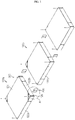
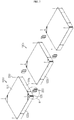
- FIG. 3 is an exploded perspective view showing battery modules and connection members in the battery pack according to the first embodiment of the present disclosure
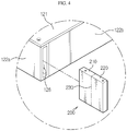
- FIG. 4 is an enlarged perspective view showing a portion A of FIG. 3
- FIG. 5 is a partial cross-sectioned view showing that the battery modules are connected by the connection members in the battery pack according to the first embodiment of the present disclosure
- FIG. 6 is a perspective view showing that the battery modules are connected by the connection member in the battery pack according to the first embodiment of the present disclosure.
- a battery pack 10 according to the first embodiment of the present disclosure includes a battery module 100 and a connection member 200.
- the battery pack 10 may be configured so that a plurality of battery modules 100 connected to each other are coupled to, for example, a plate 400.
- the battery module 100 may include a plurality of battery cells 110 and a casing member 120.
- the plurality of battery cells 110 may be stacked one another in various ways.
- the battery cells 110 may be accommodated in a cartridge assembly formed by injecting-molding plastic, and a plurality of cartridge assemblies may be stacked one another.
- the plurality of battery cells 110 may be stacked in various ways without being limited to the above.
- the casing member 120 may be configured to surround the plurality of battery cells 110.
- the casing member 120 may be configured in various ways, and, for example, may include an upper casing 121 disposed at an upper portion of the battery cells 110 and side casings 122 disposed at side portions of the battery cells 110 and coupled to the upper casing 121.
- the casings may be coupled to each other in various ways, for example by screwing, welding, riveting, bolting, pin coupling, bracketing, moment bonding or the like. Referring to FIG.
- an opening 126 having a preset size may be formed in the side casing 122, and a connection member 200, explained later, may be coupled to the opening 126 of the side casing 122 to connect a plurality of battery modules 100 to each other. Meanwhile, a lower casing disposed at a lower portion of the battery cells 110 and coupled to the side casings 122 may be further provided.
- the connection member 200 is configured to connect the plurality of battery modules 100 to each other.
- the connection member 200 includes a first insert 210 inserted into the opening 126 formed in a side casing 122a of any one battery module 100a among the plurality of battery modules 100 and a second insert 220 inserted into the opening 126 formed in a side casing 122c of another battery module 100b among the plurality of battery modules 100.
- the first insert 210 may be inserted into the opening 126 formed in the side casing 122a of any one battery module 100a among the plurality of battery modules 100 and then coupled thereto by using a screw 300 or a coupling member using a bolt and a nut.
- the second insert 220 may be inserted into the opening 126 formed in the side casing 122c of another battery module 100b among the plurality of battery modules 100 and then coupled thereto by using a screw 300 or a coupling member using a bolt and a nut.
- the opening 126 may be formed to correspond to the length of the first insert 210 or the second insert 220, for example to have the same shape.
- connection member 200 is respectively connected to the side casings 122a, 122c of the plurality of battery modules 100a, 100b to connect neighboring battery modules 100a, 100b to each other.
- a frame or the like for supporting the battery modules 100 is not necessary, and thus the battery pack may be assembled simply.
- the material cost and the processing cost are reduced, and the space occupied by the frame is unnecessary to allow the battery modules 100 to be more closely adhered to each other.
- the battery pack 100 may have an improved energy density.
- the side casing 122 not only protects the battery cells 110 but also structurally supports the battery module 100, and thus the side casing 122 may have a thickness enough to have sufficient rigidity
- connection member 200 may be fixed and coupled to the side casing 122 of the battery module 100 in various ways.
- the connection member 200 may be coupled by screws 300 or by bolts and nuts, or in a simple way using a hooking manner.
- the connection member 200 may be coupled to the side casing 122 by welding.
- the plurality of battery modules 100 may be arranged in a single layer, and the plurality of battery modules 100 may be arranged to have at least one row or at least one column. If the plurality of battery modules 100 are arranged in a single layer as above, the overall height of the battery modules 100 is lower than the case where the battery modules 100 are arranged in a plurality of layers. Thus, the plurality of battery modules 100 may be easily arranged in a space with a limited height such as an underfloor of an electric vehicle or the like.
- the battery module 100 may include a side casing 122 having an opening 126 formed therein, and the connection member 200 is inserted into the openings formed in the side casings 122a, 122c of the battery modules 100a, 100b adjacent to each other among the plurality of battery modules 100a and then coupled thereto by the screw 300 or the like. Since the plurality of battery modules 100a, 100b are connectable to each other without a frame as described above, more battery modules 100 may be disposed in the space occupied by the frame, thereby improving the energy density.
- FIG. 7 is an exploded perspective view showing battery modules and connection members in a battery pack according to the second embodiment of the present disclosure
- FIG. 8 is an enlarged perspective view showing a portion B of FIG. 7
- FIG. 9 is a partial cross-sectioned view showing that the battery modules are connected by the connection members in the battery pack according to the second embodiment of the present disclosure.
- the second embodiment of the present disclosure is different from the first embodiment in the point that a stopper 240 is formed at the connection member 200.
- the stopper 240 may be formed between the first insert 210 and the second insert 220 to prevent the first insert 210 and the second insert 220 from being inserted in excess of a predetermined range.
- a step (see a portion a in FIG. 8 ) may be formed between one side casing 122a and another side casing 122b disposed adjacent to the one side casing 122a and contacting the one side casing 122a so that the stopper 240 may be placed thereon. That is, the stopper 240 may be placed on the step a formed between the side casings 122a, 122b which are in contact with each other.
- the plurality of battery modules 100 when the plurality of battery modules 100 are connected to each other by the connection member 200, the plurality of battery modules 100 may be coupled not in a spaced state but in a contacting state (In FIG. 9 , the side casings 122b, 122d are in contact with each other) (see FIG 9 ).
- the stopper 240 may extend in a direction intersecting the direction in which the first insert 210 and the second insert 220 are formed, for example in a direction perpendicular to the direction in which the first insert 210 and the second insert 220 are formed.
- the stopper 240 may be formed to extend from a portion between the first insert 210 and the second insert 220, for example from a middle portion 230 (see FIG. 4 ) of the first insert 210 and the second insert 220.
- the extending direction and the extending position of the stopper 240 may be set in various ways.
- FIG. 10 is an exploded perspective view showing battery modules and connection members in a battery pack according to the third embodiment of the present disclosure
- FIG. 11 is an enlarged perspective view showing a portion C of FIG. 10
- FIG. 12 is a partial cross-sectioned view showing that the battery modules are connected by the connection members in the battery pack according to the third embodiment of the present disclosure.
- the third embodiment of the present disclosure is different from the second embodiment in the point that battery modules 100 adjacent to each other are spaced apart from each other by the stopper 240 formed at the connection member 200.
- the stopper 240 of the third embodiment is identical to that of the second embodiment, but in the third embodiment, a step is not formed between one side casing 122a and another side casing 122b disposed adjacent to the one side casing 122a and contacting the one side casing 122a so that the stopper 240 may be placed thereon (see a portion b in FIG. 11 ), different from the second embodiment.
- the connection member 200 is coupled to the plurality of battery modules 100, battery modules 100 adjacent to each other are spaced apart from each other.
- a predetermined gap x (see FIG. 12 ) of a predetermined interval is present between the battery modules 100 connected to each other. Air may move through the spaced gap x between the battery modules 100 to cool the battery modules 100.
- the space formed by the gap x between the battery modules 100 is used for heat dissipation of the battery modules 100.
- a vehicle (not shown) according to an embodiment of the present disclosure may include the battery pack 10 described above.
- the battery pack 10 may be used for various machines or devices using electricity and may be, for example, disposed in an electric vehicle, particularly on an underfloor of the electric vehicle.
- the electric vehicle may include not only an electric vehicle driven purely by electricity but also a hybrid electric vehicle using another kind of energy together with electric energy.
- the present disclosure is directed to a battery pack and is particularly applicable to industries associated with a secondary battery.
Landscapes
- Chemical & Material Sciences (AREA)
- Chemical Kinetics & Catalysis (AREA)
- Electrochemistry (AREA)
- General Chemical & Material Sciences (AREA)
- Engineering & Computer Science (AREA)
- Manufacturing & Machinery (AREA)
- Materials Engineering (AREA)
- Battery Mounting, Suspending (AREA)
Abstract
Description
- The present application claims priority to Korean Patent Application No.
10-2017-0036034 filed on March 22, 2017 - The present disclosure relates to a battery pack, and more particularly, to a battery pack capable of improving an energy density.
- As technology development and demand for a mobile device have increased, demand for a secondary battery as an energy source has rapidly increased. Conventionally, a nickel-cadmium battery or a hydrogen ion battery has been used as the secondary battery. However, a lithium secondary battery is recently widely used because charging and discharging is free due to rare memory effect in comparison with a nickel-based secondary battery, a self-discharge rate is very low, and an energy density is high.
- The lithium secondary battery mainly uses a lithium oxide and a carbonaceous material as a positive electrode active material and a negative electrode active material, respectively. The lithium secondary battery includes an electrode assembly in which a positive electrode plate and a negative electrode plate, respectively coated with the positive electrode active material and the negative electrode active material, are arranged with a separator therebetween, and an outer member, that is a battery case, which seals and receives the electrode assembly together with an electrolyte solution.
- The lithium secondary battery includes a positive electrode, a negative electrode, and a separator interposed therebetween and an electrolyte. Depending on which material is used for the positive electrode active material and the negative electrode active material, the lithium secondary battery is classified into a lithium ion battery (LIB) and a polymer lithium ion battery (PLIB). Generally, an electrode of the lithium secondary battery may be prepared by applying the positive or negative electrode active material to a current collector made of aluminum or copper sheet, mesh, film, foil, or the like and then drying the same.
- Recently, as the demand of hybrid electric vehicle or electric vehicle is increasing, energy storage devices such as battery packs are used more and more in the vehicles. Accordingly, there is a need to develop a battery pack having a high energy density and disposed on an underfloor of a hybrid electric vehicle or an electric vehicle.
- The present disclosure is directed to providing a battery pack having a relatively high energy density by improving the space efficiency.
- In addition, the present disclosure is directed to providing a battery pack that may be easily disposed on an underfloor of a hybrid electric vehicle or an electric vehicle.
- In one aspect of the present disclosure, there is provided a battery pack, comprising: a battery module having a plurality of stacked battery cells and a casing member surrounding the plurality of battery cells; and a connection member configured to connect the plurality of battery modules to each other.
- Also, the plurality of battery modules connected by the connection member may be arranged in a single layer.
- In addition, the plurality of battery modules may be arranged to have at least one column or at least one row.
- Also, the casing member may include: an upper casing disposed at an upper portion of the battery cells; and side casings disposed at side surfaces of the battery cells and coupled to the upper casing, and an opening having a preset size may be formed in at least one of the side casings, and the connection member may be coupled to the opening of the side casing.
- In addition, the connection member may include: a first insert inserted into the opening of the side casing of any one battery module among the plurality of battery modules; and a second insert inserted into the opening of the side casing of another battery module among the plurality of battery modules.
- Also, the connection member may further include a stopper formed between the first insert and the second insert to prevent the first insert and the second insert from being inserted in excess of a predetermined range.
- In addition, the stopper may extend from a portion between the first insert and the second insert toward a direction intersecting the direction in which the first insert and the second insert are formed.
- Also, the connection member may be fixed to the side casing by means of a screwing structure or a hooking structure.
- Meanwhile, in another aspect of the present disclosure, there is also provided a vehicle, comprising the battery pack described above.
- According to the embodiments of the present disclosure, the battery pack may have a relatively high energy density by improving the space efficiency.
- In addition, since a plurality of battery modules are arranged in a single layer, the battery pack may be easily disposed on an underfloor of a hybrid electric vehicle or an electric vehicle.
-
-
FIG. 1 is a schematic perspective view showing a battery pack according to the first embodiment of the present disclosure. -
FIG. 2 is an exploded perspective view showing a battery module in the battery pack according to the first embodiment of the present disclosure. -
FIG. 3 is an exploded perspective view showing battery modules and connection members in the battery pack according to the first embodiment of the present disclosure. -
FIG. 4 is an enlarged perspective view showing a portion A ofFIG. 3 . -
FIG. 5 is a partial cross-sectioned view showing that the battery modules are connected by the connection members in the battery pack according to the first embodiment of the present disclosure. -
FIG. 6 is a perspective view showing that the battery modules are connected by the connection member in the battery pack according to the first embodiment of the present disclosure. -
FIG. 7 is an exploded perspective view showing battery modules and connection members in a battery pack according to the second embodiment of the present disclosure. -
FIG. 8 is an enlarged perspective view showing a portion B ofFIG. 7 . -
FIG. 9 is a partial cross-sectioned view showing that the battery modules are connected by the connection members in the battery pack according to the second embodiment of the present disclosure. -
FIG. 10 is an exploded perspective view showing battery modules and connection members in a battery pack according to the third embodiment of the present disclosure. -
FIG. 11 is an enlarged perspective view showing a portion C ofFIG. 10 . -
FIG. 12 is a partial cross-sectioned view showing that the battery modules are connected by the connection members in the battery pack according to the third embodiment of the present disclosure. - Hereinafter, preferred embodiments of the present disclosure will be described in detail with reference to the accompanying drawings. Prior to the description, it should be understood that the terms used in the specification and the appended claims should not be construed as limited to general and dictionary meanings, but interpreted based on the meanings and concepts corresponding to technical aspects of the present disclosure on the basis of the principle that the inventor is allowed to define terms appropriately for the best explanation. Therefore, the description proposed herein is just a preferable example for the purpose of illustrations only, not intended to limit the scope of the disclosure, so it should be understood that other equivalents and modifications could be made thereto without departing from the scope of the disclosure.
- In the drawings, the size of each element or a specific part of the element may be exaggerated, omitted, or schematically illustrated for convenience and clarity of a description. Thus, the size of each element does not entirely reflect the actual size of the element. A detailed description of well-known functions or elements associated with the present disclosure will be omitted if it unnecessarily obscures the subject matter of the present disclosure.
- The term, 'combine' or 'connect' as used herein, may refer not only to a case where one member and another member are directly combined or directly connected but also a case where one member is indirectly combined with another member via a connecting member or is indirectly connected.
-
FIG. 1 is a schematic perspective view showing a battery pack according to the first embodiment of the present disclosure,FIG. 2 is an exploded perspective view showing a battery module in the battery pack according to the first embodiment of the present disclosure,FIG. 3 is an exploded perspective view showing battery modules and connection members in the battery pack according to the first embodiment of the present disclosure,FIG. 4 is an enlarged perspective view showing a portion A ofFIG. 3 ,FIG. 5 is a partial cross-sectioned view showing that the battery modules are connected by the connection members in the battery pack according to the first embodiment of the present disclosure, andFIG. 6 is a perspective view showing that the battery modules are connected by the connection member in the battery pack according to the first embodiment of the present disclosure. - Referring to
FIGS. 1 to 6 , abattery pack 10 according to the first embodiment of the present disclosure includes abattery module 100 and aconnection member 200. Referring toFIG. 1 , thebattery pack 10 may be configured so that a plurality ofbattery modules 100 connected to each other are coupled to, for example, aplate 400. - Referring to
FIG. 2 , thebattery module 100 may include a plurality ofbattery cells 110 and acasing member 120. - The plurality of
battery cells 110 may be stacked one another in various ways. For example, thebattery cells 110 may be accommodated in a cartridge assembly formed by injecting-molding plastic, and a plurality of cartridge assemblies may be stacked one another. However, the plurality ofbattery cells 110 may be stacked in various ways without being limited to the above. - The
casing member 120 may be configured to surround the plurality ofbattery cells 110. Thecasing member 120 may be configured in various ways, and, for example, may include anupper casing 121 disposed at an upper portion of thebattery cells 110 andside casings 122 disposed at side portions of thebattery cells 110 and coupled to theupper casing 121. Here, the casings may be coupled to each other in various ways, for example by screwing, welding, riveting, bolting, pin coupling, bracketing, moment bonding or the like. Referring toFIG. 2 , an opening 126 having a preset size may be formed in theside casing 122, and aconnection member 200, explained later, may be coupled to theopening 126 of theside casing 122 to connect a plurality ofbattery modules 100 to each other. Meanwhile, a lower casing disposed at a lower portion of thebattery cells 110 and coupled to theside casings 122 may be further provided. - The
connection member 200 is configured to connect the plurality ofbattery modules 100 to each other. Referring toFIGS. 3 to 5 , theconnection member 200 includes afirst insert 210 inserted into the opening 126 formed in aside casing 122a of any onebattery module 100a among the plurality ofbattery modules 100 and asecond insert 220 inserted into the opening 126 formed in aside casing 122c of anotherbattery module 100b among the plurality ofbattery modules 100. Thefirst insert 210 may be inserted into theopening 126 formed in theside casing 122a of any onebattery module 100a among the plurality ofbattery modules 100 and then coupled thereto by using ascrew 300 or a coupling member using a bolt and a nut. Also, thesecond insert 220 may be inserted into theopening 126 formed in theside casing 122c of anotherbattery module 100b among the plurality ofbattery modules 100 and then coupled thereto by using ascrew 300 or a coupling member using a bolt and a nut. Here, theopening 126 may be formed to correspond to the length of thefirst insert 210 or thesecond insert 220, for example to have the same shape. - Referring to
FIGS. 3 and6 , theconnection member 200 is respectively connected to theside casings battery modules battery modules battery modules 100 is not necessary, and thus the battery pack may be assembled simply. Thus, the material cost and the processing cost are reduced, and the space occupied by the frame is unnecessary to allow thebattery modules 100 to be more closely adhered to each other. For this reason, thebattery pack 100 may have an improved energy density. Here, theside casing 122 not only protects thebattery cells 110 but also structurally supports thebattery module 100, and thus theside casing 122 may have a thickness enough to have sufficient rigidity - The
connection member 200 may be fixed and coupled to theside casing 122 of thebattery module 100 in various ways. For example, theconnection member 200 may be coupled byscrews 300 or by bolts and nuts, or in a simple way using a hooking manner. Alternatively, theconnection member 200 may be coupled to theside casing 122 by welding. - Referring to
FIGS. 1 and3 , after the plurality ofbattery modules 100 are connected by theconnection member 200, the plurality ofbattery modules 100 may be arranged in a single layer, and the plurality ofbattery modules 100 may be arranged to have at least one row or at least one column. If the plurality ofbattery modules 100 are arranged in a single layer as above, the overall height of thebattery modules 100 is lower than the case where thebattery modules 100 are arranged in a plurality of layers. Thus, the plurality ofbattery modules 100 may be easily arranged in a space with a limited height such as an underfloor of an electric vehicle or the like. - Hereinafter, the operation and effect of the
battery pack 10 according to the first embodiment of the present disclosure will be described. - Referring to
FIG. 3 , thebattery module 100 may include aside casing 122 having anopening 126 formed therein, and theconnection member 200 is inserted into the openings formed in theside casings battery modules battery modules 100a and then coupled thereto by thescrew 300 or the like. Since the plurality ofbattery modules more battery modules 100 may be disposed in the space occupied by the frame, thereby improving the energy density. -
FIG. 7 is an exploded perspective view showing battery modules and connection members in a battery pack according to the second embodiment of the present disclosure,FIG. 8 is an enlarged perspective view showing a portion B ofFIG. 7 , andFIG. 9 is a partial cross-sectioned view showing that the battery modules are connected by the connection members in the battery pack according to the second embodiment of the present disclosure. - Hereinafter, the function and effect of a
battery pack 10 according to the second embodiment according to the present disclosure will be described with reference to the drawings, but features common to thebattery pack 10 according to the first embodiment of the present disclosure will not be described again in detail. - The second embodiment of the present disclosure is different from the first embodiment in the point that a
stopper 240 is formed at theconnection member 200. - Referring to
FIGS. 7 and8 , thestopper 240 may be formed between thefirst insert 210 and thesecond insert 220 to prevent thefirst insert 210 and thesecond insert 220 from being inserted in excess of a predetermined range. In addition, a step (see a portion a inFIG. 8 ) may be formed between oneside casing 122a and anotherside casing 122b disposed adjacent to the oneside casing 122a and contacting the oneside casing 122a so that thestopper 240 may be placed thereon. That is, thestopper 240 may be placed on the step a formed between theside casings battery modules 100 are connected to each other by theconnection member 200, the plurality ofbattery modules 100 may be coupled not in a spaced state but in a contacting state (InFIG. 9 , theside casings FIG 9 ). - Referring to
FIGS. 7 to 9 , thestopper 240 may extend in a direction intersecting the direction in which thefirst insert 210 and thesecond insert 220 are formed, for example in a direction perpendicular to the direction in which thefirst insert 210 and thesecond insert 220 are formed. In addition, thestopper 240 may be formed to extend from a portion between thefirst insert 210 and thesecond insert 220, for example from a middle portion 230 (seeFIG. 4 ) of thefirst insert 210 and thesecond insert 220. However, the extending direction and the extending position of thestopper 240 may be set in various ways. -
FIG. 10 is an exploded perspective view showing battery modules and connection members in a battery pack according to the third embodiment of the present disclosure,FIG. 11 is an enlarged perspective view showing a portion C ofFIG. 10 , andFIG. 12 is a partial cross-sectioned view showing that the battery modules are connected by the connection members in the battery pack according to the third embodiment of the present disclosure. - Hereinafter, the function and effect of a
battery pack 10 according to the third embodiment according to the present disclosure will be described with reference to the drawings, but features common to thebattery pack 10 according to the first or second embodiment of the present disclosure will not be described again in detail. - The third embodiment of the present disclosure is different from the second embodiment in the point that
battery modules 100 adjacent to each other are spaced apart from each other by thestopper 240 formed at theconnection member 200. - Referring to
FIGS. 10 to 12 , thestopper 240 of the third embodiment is identical to that of the second embodiment, but in the third embodiment, a step is not formed between oneside casing 122a and anotherside casing 122b disposed adjacent to the oneside casing 122a and contacting the oneside casing 122a so that thestopper 240 may be placed thereon (see a portion b inFIG. 11 ), different from the second embodiment. Thus, if theconnection member 200 is coupled to the plurality ofbattery modules 100,battery modules 100 adjacent to each other are spaced apart from each other. In other words, a predetermined gap x (seeFIG. 12 ) of a predetermined interval is present between thebattery modules 100 connected to each other. Air may move through the spaced gap x between thebattery modules 100 to cool thebattery modules 100. In other words, the space formed by the gap x between thebattery modules 100 is used for heat dissipation of thebattery modules 100. - Meanwhile, a vehicle (not shown) according to an embodiment of the present disclosure may include the
battery pack 10 described above. Thebattery pack 10 may be used for various machines or devices using electricity and may be, for example, disposed in an electric vehicle, particularly on an underfloor of the electric vehicle. Here, the electric vehicle may include not only an electric vehicle driven purely by electricity but also a hybrid electric vehicle using another kind of energy together with electric energy. - The present disclosure has been described in detail. However, it should be understood that the detailed description and specific examples, while indicating preferred embodiments of the disclosure, are given by way of illustration only, since various changes and modifications within the scope of the disclosure will become apparent to those skilled in the art from this detailed description.
- The present disclosure is directed to a battery pack and is particularly applicable to industries associated with a secondary battery.
Claims (9)
- A battery pack, comprising:a battery module having a plurality of stacked battery cells and a casing member surrounding the plurality of battery cells; anda connection member configured to connect the plurality of battery modules to each other.
- The battery pack according to claim 1,
wherein the plurality of battery modules connected by the connection member are arranged in a single layer. - The battery pack according to claim 2,
wherein the plurality of battery modules are arranged to have at least one column or at least one row. - The battery pack according to claim 1,
wherein the casing member includes:an upper casing disposed at an upper portion of the battery cells; andside casings disposed at side surfaces of the battery cells and coupled to the upper casing,wherein an opening having a preset size is formed in at least one of the side casings, and the connection member is coupled to the opening of the side casing. - The battery pack according to claim 4,
wherein the connection member includes:a first insert inserted into the opening of the side casing of any one battery module among the plurality of battery modules; anda second insert inserted into the opening of the side casing of another battery module among the plurality of battery modules. - The battery pack according to claim 5,
wherein the connection member further includes a stopper formed between the first insert and the second insert to prevent the first insert and the second insert from being inserted in excess of a predetermined range. - The battery pack according to claim 6,
wherein the stopper extends from a portion between the first insert and the second insert toward a direction intersecting the direction in which the first insert and the second insert are formed. - The battery pack according to claim 4,
wherein the connection member is fixed to the side casing by means of a screwing structure or a hooking structure. - A vehicle, comprising the battery pack defined in any one of claims 1 to 8.
Priority Applications (1)
| Application Number | Priority Date | Filing Date | Title |
|---|---|---|---|
| PL18770779T PL3467903T3 (en) | 2017-03-22 | 2018-01-04 | Battery pack |
Applications Claiming Priority (2)
| Application Number | Priority Date | Filing Date | Title |
|---|---|---|---|
| KR1020170036034A KR102110543B1 (en) | 2017-03-22 | 2017-03-22 | Battery pack |
| PCT/KR2018/000199 WO2018174388A1 (en) | 2017-03-22 | 2018-01-04 | Battery pack |
Publications (3)
| Publication Number | Publication Date |
|---|---|
| EP3467903A1 true EP3467903A1 (en) | 2019-04-10 |
| EP3467903A4 EP3467903A4 (en) | 2019-09-25 |
| EP3467903B1 EP3467903B1 (en) | 2020-07-01 |
Family
ID=63584636
Family Applications (1)
| Application Number | Title | Priority Date | Filing Date |
|---|---|---|---|
| EP18770779.9A Active EP3467903B1 (en) | 2017-03-22 | 2018-01-04 | Battery pack |
Country Status (7)
| Country | Link |
|---|---|
| US (2) | US11605857B2 (en) |
| EP (1) | EP3467903B1 (en) |
| JP (1) | JP6763981B2 (en) |
| KR (1) | KR102110543B1 (en) |
| CN (2) | CN109478620B (en) |
| PL (1) | PL3467903T3 (en) |
| WO (1) | WO2018174388A1 (en) |
Families Citing this family (5)
| Publication number | Priority date | Publication date | Assignee | Title |
|---|---|---|---|---|
| CN110993845B (en) * | 2019-11-18 | 2021-12-07 | 比亚迪股份有限公司 | Battery pack and electric vehicle |
| KR102433361B1 (en) | 2019-12-17 | 2022-08-16 | 주식회사 엘지에너지솔루션 | Battery module and battery pack including the same |
| KR20220014027A (en) * | 2020-07-28 | 2022-02-04 | 에스케이온 주식회사 | Battery pack |
| US20240170791A1 (en) * | 2021-12-27 | 2024-05-23 | Lg Energy Solution, Ltd. | Battery pack |
| CN117501534A (en) * | 2021-12-27 | 2024-02-02 | 株式会社Lg新能源 | Battery pack |
Family Cites Families (35)
| Publication number | Priority date | Publication date | Assignee | Title |
|---|---|---|---|---|
| US5496657A (en) | 1994-03-16 | 1996-03-05 | Dixon, Jr.; Alfred R. | Modular battery system comprising individual interconnected modules |
| US5981101A (en) * | 1997-06-02 | 1999-11-09 | Gnb Technologies, Inc. | Modular cell tray assembly for sealed lead-acid cells |
| JP2002205555A (en) * | 2001-01-12 | 2002-07-23 | Suzuki Motor Corp | Battery fixing structure for vehicle |
| JP2007048637A (en) * | 2005-08-10 | 2007-02-22 | Nissan Motor Co Ltd | Battery pack and case for battery pack |
| JP2010129860A (en) * | 2008-11-28 | 2010-06-10 | Power System:Kk | Electricity accumulating module equipped with three-directional positioning mechanism |
| JP5497318B2 (en) * | 2009-03-27 | 2014-05-21 | 株式会社日本総合研究所 | Battery package, battery module, and battery pack |
| EP2325922B1 (en) * | 2009-11-19 | 2012-05-09 | SB LiMotive Co., Ltd. | Battery pack |
| US20110165451A1 (en) | 2010-01-05 | 2011-07-07 | Myung-Chul Kim | Battery pack |
| KR101297176B1 (en) | 2010-06-03 | 2013-08-21 | 주식회사 엘지화학 | Battery Module Having Novel Structure |
| JP5601960B2 (en) * | 2010-10-14 | 2014-10-08 | 株式会社東芝 | Power storage system |
| KR101212552B1 (en) | 2010-11-29 | 2012-12-14 | 한국과학기술원 | Structure for electric vehicle battery pack |
| CN102792483A (en) | 2011-01-25 | 2012-11-21 | 松下电器产业株式会社 | Battery module and battery assembly used therein |
| CN102812578A (en) * | 2011-01-25 | 2012-12-05 | 松下电器产业株式会社 | Battery module and battery assembly used therein |
| US9196880B2 (en) | 2011-01-26 | 2015-11-24 | Samsung Sdi Co., Ltd. | Battery module with offset battery cells |
| JP2013186995A (en) | 2012-03-07 | 2013-09-19 | Nissan Motor Co Ltd | Battery pack |
| JP5598883B2 (en) * | 2012-03-16 | 2014-10-01 | ワイティーエス・サイエンス・プロパティーズ・プライベート・リミテッド | Magnesium-air battery fuel element, magnesium-air battery, method for producing magnesium-air battery fuel element, magnesium-air battery system, and method of using magnesium-air battery system |
| US20130260611A1 (en) * | 2012-04-03 | 2013-10-03 | Jang-Gun Ahn | Battery module |
| JP5978847B2 (en) | 2012-08-09 | 2016-08-24 | 株式会社豊田自動織機 | Battery pack |
| DE102012015818B4 (en) * | 2012-08-10 | 2023-10-26 | Dr. Ing. H.C. F. Porsche Ag | Motor vehicle battery |
| JP5623483B2 (en) | 2012-09-18 | 2014-11-12 | トヨタ自動車株式会社 | Battery, battery pack, battery manufacturing method |
| JP6238106B2 (en) | 2013-04-08 | 2017-11-29 | 株式会社Gsユアサ | Power storage module, power storage device, and air path connecting member |
| WO2014178565A1 (en) * | 2013-04-29 | 2014-11-06 | 주식회사 엘지화학 | Battery module comprised in battery pack for motor vehicle |
| KR101486928B1 (en) | 2013-04-29 | 2015-02-04 | 주식회사 엘지화학 | Battery module assembly for vehicle's battery pack |
| DE102013010001A1 (en) | 2013-06-14 | 2014-12-18 | Leopold Kostal Gmbh & Co. Kg | Stationary storage battery and energy storage module |
| CN104685663B (en) * | 2013-10-01 | 2017-09-08 | 株式会社Lg 化学 | Battery unit and the battery module using the battery unit |
| KR101814106B1 (en) | 2013-10-04 | 2018-01-02 | 주식회사 엘지화학 | Connector and battery pack including the same |
| KR101649154B1 (en) | 2014-02-24 | 2016-08-18 | 엘지전자 주식회사 | Battery Pack |
| EP2916366B1 (en) * | 2014-03-05 | 2018-01-31 | Volvo Car Corporation | Energy storage enclosure |
| US9356270B2 (en) * | 2014-08-20 | 2016-05-31 | Ford Global Technologies, Llc | Multi-tier traction battery assembly with alignment feature |
| JP6358065B2 (en) | 2014-12-04 | 2018-07-18 | 株式会社村田製作所 | Battery pack and electrical equipment |
| JP6543830B2 (en) * | 2015-02-17 | 2019-07-17 | 藤倉コンポジット株式会社 | Assembled battery |
| JP6552034B2 (en) * | 2015-02-17 | 2019-07-31 | 藤倉コンポジット株式会社 | Metal air battery unit and metal air battery |
| US10003052B2 (en) * | 2015-03-10 | 2018-06-19 | Ford Global Technologies, Llc | Compression limiters for electrified vehicle battery assemblies |
| KR101805652B1 (en) * | 2015-08-28 | 2017-12-06 | 삼성에스디아이 주식회사 | Rechargeable battery pack |
| DE102016204681A1 (en) * | 2016-03-22 | 2017-09-28 | Robert Bosch Gmbh | Battery and method of manufacturing a battery |
-
2017
- 2017-03-22 KR KR1020170036034A patent/KR102110543B1/en active IP Right Grant
-
2018
- 2018-01-04 WO PCT/KR2018/000199 patent/WO2018174388A1/en unknown
- 2018-01-04 JP JP2018567851A patent/JP6763981B2/en active Active
- 2018-01-04 PL PL18770779T patent/PL3467903T3/en unknown
- 2018-01-04 EP EP18770779.9A patent/EP3467903B1/en active Active
- 2018-01-04 CN CN201880002808.XA patent/CN109478620B/en active Active
- 2018-01-04 US US16/310,539 patent/US11605857B2/en active Active
- 2018-02-08 CN CN201820223096.1U patent/CN208336354U/en active Active
-
2022
- 2022-12-13 US US18/080,544 patent/US20230112307A1/en active Pending
Also Published As
| Publication number | Publication date |
|---|---|
| JP2019520680A (en) | 2019-07-18 |
| WO2018174388A1 (en) | 2018-09-27 |
| US20230112307A1 (en) | 2023-04-13 |
| CN109478620B (en) | 2022-04-08 |
| PL3467903T3 (en) | 2020-11-16 |
| US20190334137A1 (en) | 2019-10-31 |
| EP3467903B1 (en) | 2020-07-01 |
| EP3467903A4 (en) | 2019-09-25 |
| CN208336354U (en) | 2019-01-04 |
| CN109478620A (en) | 2019-03-15 |
| JP6763981B2 (en) | 2020-09-30 |
| KR20180107569A (en) | 2018-10-02 |
| US11605857B2 (en) | 2023-03-14 |
| KR102110543B1 (en) | 2020-05-13 |
Similar Documents
| Publication | Publication Date | Title |
|---|---|---|
| US11121395B2 (en) | Battery module with movable end plate responsive to cell swelling and battery pack including same | |
| EP3671945B1 (en) | Battery pack | |
| EP3540817B1 (en) | Battery pack | |
| EP3467903B1 (en) | Battery pack | |
| US9543550B2 (en) | Battery cell module, battery, and motor vehicle | |
| KR101761825B1 (en) | Battery module, and battery pack including the same | |
| US10468643B2 (en) | Battery module and battery pack including the same | |
| US20220223931A1 (en) | Battery Module, and Battery Pack and Vehicle Comprising Same | |
| JP7154652B2 (en) | Battery packs and devices containing them | |
| EP3907811A1 (en) | Battery module and battery pack comprising same | |
| EP3772122B1 (en) | Battery module with a multifunctional end-plate | |
| KR20160066919A (en) | Battery module, and battery module manufacturing method | |
| US20220158284A1 (en) | Battery Module and Battery Pack Including the Same | |
| JP6789388B2 (en) | Battery module and battery pack containing it | |
| EP4184666A1 (en) | Battery pack and device including same | |
| KR20210074817A (en) | Cell Module With a Simple Assembly Structure |
Legal Events
| Date | Code | Title | Description |
|---|---|---|---|
| STAA | Information on the status of an ep patent application or granted ep patent |
Free format text: STATUS: THE INTERNATIONAL PUBLICATION HAS BEEN MADE |
|
| PUAI | Public reference made under article 153(3) epc to a published international application that has entered the european phase |
Free format text: ORIGINAL CODE: 0009012 |
|
| STAA | Information on the status of an ep patent application or granted ep patent |
Free format text: STATUS: REQUEST FOR EXAMINATION WAS MADE |
|
| 17P | Request for examination filed |
Effective date: 20190107 |
|
| AK | Designated contracting states |
Kind code of ref document: A1 Designated state(s): AL AT BE BG CH CY CZ DE DK EE ES FI FR GB GR HR HU IE IS IT LI LT LU LV MC MK MT NL NO PL PT RO RS SE SI SK SM TR |
|
| AX | Request for extension of the european patent |
Extension state: BA ME |
|
| RIC1 | Information provided on ipc code assigned before grant |
Ipc: H01M 10/0525 20100101ALI20190712BHEP Ipc: H01M 2/10 20060101AFI20190712BHEP |
|
| A4 | Supplementary search report drawn up and despatched |
Effective date: 20190822 |
|
| RIC1 | Information provided on ipc code assigned before grant |
Ipc: H01M 2/10 20060101AFI20190816BHEP Ipc: H01M 10/0525 20100101ALI20190816BHEP |
|
| GRAP | Despatch of communication of intention to grant a patent |
Free format text: ORIGINAL CODE: EPIDOSNIGR1 |
|
| STAA | Information on the status of an ep patent application or granted ep patent |
Free format text: STATUS: GRANT OF PATENT IS INTENDED |
|
| RIC1 | Information provided on ipc code assigned before grant |
Ipc: H01M 2/10 20060101AFI20200312BHEP Ipc: H01M 10/0525 20100101ALN20200312BHEP |
|
| RIC1 | Information provided on ipc code assigned before grant |
Ipc: H01M 10/0525 20100101ALN20200324BHEP Ipc: H01M 2/10 20060101AFI20200324BHEP |
|
| INTG | Intention to grant announced |
Effective date: 20200408 |
|
| GRAS | Grant fee paid |
Free format text: ORIGINAL CODE: EPIDOSNIGR3 |
|
| DAX | Request for extension of the european patent (deleted) | ||
| GRAA | (expected) grant |
Free format text: ORIGINAL CODE: 0009210 |
|
| STAA | Information on the status of an ep patent application or granted ep patent |
Free format text: STATUS: THE PATENT HAS BEEN GRANTED |
|
| DAV | Request for validation of the european patent (deleted) | ||
| AK | Designated contracting states |
Kind code of ref document: B1 Designated state(s): AL AT BE BG CH CY CZ DE DK EE ES FI FR GB GR HR HU IE IS IT LI LT LU LV MC MK MT NL NO PL PT RO RS SE SI SK SM TR |
|
| REG | Reference to a national code |
Ref country code: AT Ref legal event code: REF Ref document number: 1286985 Country of ref document: AT Kind code of ref document: T Effective date: 20200715 Ref country code: CH Ref legal event code: EP |
|
| REG | Reference to a national code |
Ref country code: IE Ref legal event code: FG4D |
|
| REG | Reference to a national code |
Ref country code: DE Ref legal event code: R096 Ref document number: 602018005741 Country of ref document: DE |
|
| REG | Reference to a national code |
Ref country code: LT Ref legal event code: MG4D |
|
| REG | Reference to a national code |
Ref country code: DE Ref legal event code: R079 Ref document number: 602018005741 Country of ref document: DE Free format text: PREVIOUS MAIN CLASS: H01M0002100000 Ipc: H01M0050200000 |
|
| PG25 | Lapsed in a contracting state [announced via postgrant information from national office to epo] |
Ref country code: BG Free format text: LAPSE BECAUSE OF FAILURE TO SUBMIT A TRANSLATION OF THE DESCRIPTION OR TO PAY THE FEE WITHIN THE PRESCRIBED TIME-LIMIT Effective date: 20201001 |
|
| REG | Reference to a national code |
Ref country code: NL Ref legal event code: MP Effective date: 20200701 |
|
| REG | Reference to a national code |
Ref country code: AT Ref legal event code: MK05 Ref document number: 1286985 Country of ref document: AT Kind code of ref document: T Effective date: 20200701 |
|
| PG25 | Lapsed in a contracting state [announced via postgrant information from national office to epo] |
Ref country code: PT Free format text: LAPSE BECAUSE OF FAILURE TO SUBMIT A TRANSLATION OF THE DESCRIPTION OR TO PAY THE FEE WITHIN THE PRESCRIBED TIME-LIMIT Effective date: 20201102 Ref country code: CZ Free format text: LAPSE BECAUSE OF FAILURE TO SUBMIT A TRANSLATION OF THE DESCRIPTION OR TO PAY THE FEE WITHIN THE PRESCRIBED TIME-LIMIT Effective date: 20200701 Ref country code: ES Free format text: LAPSE BECAUSE OF FAILURE TO SUBMIT A TRANSLATION OF THE DESCRIPTION OR TO PAY THE FEE WITHIN THE PRESCRIBED TIME-LIMIT Effective date: 20200701 Ref country code: HR Free format text: LAPSE BECAUSE OF FAILURE TO SUBMIT A TRANSLATION OF THE DESCRIPTION OR TO PAY THE FEE WITHIN THE PRESCRIBED TIME-LIMIT Effective date: 20200701 Ref country code: AT Free format text: LAPSE BECAUSE OF FAILURE TO SUBMIT A TRANSLATION OF THE DESCRIPTION OR TO PAY THE FEE WITHIN THE PRESCRIBED TIME-LIMIT Effective date: 20200701 Ref country code: LT Free format text: LAPSE BECAUSE OF FAILURE TO SUBMIT A TRANSLATION OF THE DESCRIPTION OR TO PAY THE FEE WITHIN THE PRESCRIBED TIME-LIMIT Effective date: 20200701 Ref country code: SE Free format text: LAPSE BECAUSE OF FAILURE TO SUBMIT A TRANSLATION OF THE DESCRIPTION OR TO PAY THE FEE WITHIN THE PRESCRIBED TIME-LIMIT Effective date: 20200701 Ref country code: FI Free format text: LAPSE BECAUSE OF FAILURE TO SUBMIT A TRANSLATION OF THE DESCRIPTION OR TO PAY THE FEE WITHIN THE PRESCRIBED TIME-LIMIT Effective date: 20200701 Ref country code: GR Free format text: LAPSE BECAUSE OF FAILURE TO SUBMIT A TRANSLATION OF THE DESCRIPTION OR TO PAY THE FEE WITHIN THE PRESCRIBED TIME-LIMIT Effective date: 20201002 Ref country code: NO Free format text: LAPSE BECAUSE OF FAILURE TO SUBMIT A TRANSLATION OF THE DESCRIPTION OR TO PAY THE FEE WITHIN THE PRESCRIBED TIME-LIMIT Effective date: 20201001 |
|
| PG25 | Lapsed in a contracting state [announced via postgrant information from national office to epo] |
Ref country code: IS Free format text: LAPSE BECAUSE OF FAILURE TO SUBMIT A TRANSLATION OF THE DESCRIPTION OR TO PAY THE FEE WITHIN THE PRESCRIBED TIME-LIMIT Effective date: 20201101 Ref country code: RS Free format text: LAPSE BECAUSE OF FAILURE TO SUBMIT A TRANSLATION OF THE DESCRIPTION OR TO PAY THE FEE WITHIN THE PRESCRIBED TIME-LIMIT Effective date: 20200701 Ref country code: LV Free format text: LAPSE BECAUSE OF FAILURE TO SUBMIT A TRANSLATION OF THE DESCRIPTION OR TO PAY THE FEE WITHIN THE PRESCRIBED TIME-LIMIT Effective date: 20200701 |
|
| PG25 | Lapsed in a contracting state [announced via postgrant information from national office to epo] |
Ref country code: NL Free format text: LAPSE BECAUSE OF FAILURE TO SUBMIT A TRANSLATION OF THE DESCRIPTION OR TO PAY THE FEE WITHIN THE PRESCRIBED TIME-LIMIT Effective date: 20200701 |
|
| REG | Reference to a national code |
Ref country code: DE Ref legal event code: R097 Ref document number: 602018005741 Country of ref document: DE |
|
| PG25 | Lapsed in a contracting state [announced via postgrant information from national office to epo] |
Ref country code: EE Free format text: LAPSE BECAUSE OF FAILURE TO SUBMIT A TRANSLATION OF THE DESCRIPTION OR TO PAY THE FEE WITHIN THE PRESCRIBED TIME-LIMIT Effective date: 20200701 Ref country code: DK Free format text: LAPSE BECAUSE OF FAILURE TO SUBMIT A TRANSLATION OF THE DESCRIPTION OR TO PAY THE FEE WITHIN THE PRESCRIBED TIME-LIMIT Effective date: 20200701 Ref country code: RO Free format text: LAPSE BECAUSE OF FAILURE TO SUBMIT A TRANSLATION OF THE DESCRIPTION OR TO PAY THE FEE WITHIN THE PRESCRIBED TIME-LIMIT Effective date: 20200701 Ref country code: SM Free format text: LAPSE BECAUSE OF FAILURE TO SUBMIT A TRANSLATION OF THE DESCRIPTION OR TO PAY THE FEE WITHIN THE PRESCRIBED TIME-LIMIT Effective date: 20200701 Ref country code: IT Free format text: LAPSE BECAUSE OF FAILURE TO SUBMIT A TRANSLATION OF THE DESCRIPTION OR TO PAY THE FEE WITHIN THE PRESCRIBED TIME-LIMIT Effective date: 20200701 |
|
| PLBE | No opposition filed within time limit |
Free format text: ORIGINAL CODE: 0009261 |
|
| STAA | Information on the status of an ep patent application or granted ep patent |
Free format text: STATUS: NO OPPOSITION FILED WITHIN TIME LIMIT |
|
| PG25 | Lapsed in a contracting state [announced via postgrant information from national office to epo] |
Ref country code: AL Free format text: LAPSE BECAUSE OF FAILURE TO SUBMIT A TRANSLATION OF THE DESCRIPTION OR TO PAY THE FEE WITHIN THE PRESCRIBED TIME-LIMIT Effective date: 20200701 |
|
| 26N | No opposition filed |
Effective date: 20210406 |
|
| PG25 | Lapsed in a contracting state [announced via postgrant information from national office to epo] |
Ref country code: SK Free format text: LAPSE BECAUSE OF FAILURE TO SUBMIT A TRANSLATION OF THE DESCRIPTION OR TO PAY THE FEE WITHIN THE PRESCRIBED TIME-LIMIT Effective date: 20200701 |
|
| PG25 | Lapsed in a contracting state [announced via postgrant information from national office to epo] |
Ref country code: MC Free format text: LAPSE BECAUSE OF FAILURE TO SUBMIT A TRANSLATION OF THE DESCRIPTION OR TO PAY THE FEE WITHIN THE PRESCRIBED TIME-LIMIT Effective date: 20200701 Ref country code: SI Free format text: LAPSE BECAUSE OF FAILURE TO SUBMIT A TRANSLATION OF THE DESCRIPTION OR TO PAY THE FEE WITHIN THE PRESCRIBED TIME-LIMIT Effective date: 20200701 |
|
| REG | Reference to a national code |
Ref country code: CH Ref legal event code: PL |
|
| PG25 | Lapsed in a contracting state [announced via postgrant information from national office to epo] |
Ref country code: LU Free format text: LAPSE BECAUSE OF NON-PAYMENT OF DUE FEES Effective date: 20210104 |
|
| REG | Reference to a national code |
Ref country code: BE Ref legal event code: MM Effective date: 20210131 |
|
| PG25 | Lapsed in a contracting state [announced via postgrant information from national office to epo] |
Ref country code: CH Free format text: LAPSE BECAUSE OF NON-PAYMENT OF DUE FEES Effective date: 20210131 Ref country code: LI Free format text: LAPSE BECAUSE OF NON-PAYMENT OF DUE FEES Effective date: 20210131 |
|
| PG25 | Lapsed in a contracting state [announced via postgrant information from national office to epo] |
Ref country code: IE Free format text: LAPSE BECAUSE OF NON-PAYMENT OF DUE FEES Effective date: 20210104 |
|
| PG25 | Lapsed in a contracting state [announced via postgrant information from national office to epo] |
Ref country code: BE Free format text: LAPSE BECAUSE OF NON-PAYMENT OF DUE FEES Effective date: 20210131 |
|
| REG | Reference to a national code |
Ref country code: DE Ref legal event code: R081 Ref document number: 602018005741 Country of ref document: DE Owner name: LG ENERGY SOLUTION, LTD., KR Free format text: FORMER OWNER: LG CHEM. LTD., SEOUL, KR |
|
| P01 | Opt-out of the competence of the unified patent court (upc) registered |
Effective date: 20230512 |
|
| PG25 | Lapsed in a contracting state [announced via postgrant information from national office to epo] |
Ref country code: CY Free format text: LAPSE BECAUSE OF FAILURE TO SUBMIT A TRANSLATION OF THE DESCRIPTION OR TO PAY THE FEE WITHIN THE PRESCRIBED TIME-LIMIT Effective date: 20200701 |
|
| PG25 | Lapsed in a contracting state [announced via postgrant information from national office to epo] |
Ref country code: HU Free format text: LAPSE BECAUSE OF FAILURE TO SUBMIT A TRANSLATION OF THE DESCRIPTION OR TO PAY THE FEE WITHIN THE PRESCRIBED TIME-LIMIT; INVALID AB INITIO Effective date: 20180104 |
|
| REG | Reference to a national code |
Ref country code: GB Ref legal event code: 732E Free format text: REGISTERED BETWEEN 20230824 AND 20230831 |
|
| PGFP | Annual fee paid to national office [announced via postgrant information from national office to epo] |
Ref country code: GB Payment date: 20231220 Year of fee payment: 7 |
|
| PGFP | Annual fee paid to national office [announced via postgrant information from national office to epo] |
Ref country code: FR Payment date: 20231222 Year of fee payment: 7 |
|
| PGFP | Annual fee paid to national office [announced via postgrant information from national office to epo] |
Ref country code: PL Payment date: 20231221 Year of fee payment: 7 |
|
| PG25 | Lapsed in a contracting state [announced via postgrant information from national office to epo] |
Ref country code: MK Free format text: LAPSE BECAUSE OF FAILURE TO SUBMIT A TRANSLATION OF THE DESCRIPTION OR TO PAY THE FEE WITHIN THE PRESCRIBED TIME-LIMIT Effective date: 20200701 |
|
| PGFP | Annual fee paid to national office [announced via postgrant information from national office to epo] |
Ref country code: DE Payment date: 20231220 Year of fee payment: 7 |